Embed Size (px)
Citation preview
NMI R 81 Dynamic Measuring Devices and Systems for Cryogenic Liquids
(OIML R 81:1998(E), IDT and OIML R 81:2006(E), IDT) The English versions of international standards OIML R 81:1998 Dynamic Measuring Devices and Systems for Cryogenic Liquids and OIML R 81:2006 Annex D Test Report Format are adopted as an identical national standard with the reference number NMI R 81

ii
© Commonwealth of Australia 2009
First edition — August 2009
National Measurement Institute Bradfield Road, Lindfield, NSW 2070 PO Box 264, Lindfield, NSW 2070
T (61 2) 8467 3600 F (61 2) 8467 3610 W www.measurement.gov.au
iii
1. SCOPE
NMI R 81 provides the metrological and technical requirements, the test procedures and a test report format for measuring devices and systems used for the dynamic measurement of cryogenic liquids used for trade in Australia.
2. CONTENTS
NMI R 81 is comprised of the following international recommendations published by the International Organisation of Legal Metrology (OIML):
• OIML R 81. Dynamic Measuring Devices and Systems for Cryogenic Liquids (1998); and
• OIML R 81 Annex D. Test Report Format (1996).
3. VARIATIONS AND INTERPRETATIONS
Minor variations apply to NMI R 81and are reproduced in full below. In the electronic pdf version of this publication, hover over (or right click) the highlighted text to view the variation.
• OIML R 117 is equivalent to NMI R 117.
• OIML R 105 is equivalent to NMI R 105.
• Refer to the following bibliography for the most recent edition of each publication.
IEC 60068-2-1 (2007) Environmental Testing. Part 2-1: Tests — Test A: Cold
IEC 60068-2-2 (2007) Environmental Testing. Part 2-2: Tests. Test B: Dry Heat
IEC 60068-2-6 (2007) Environmental Testing - Part 2-6: Tests - Test Fc: Vibration (Sinusoidal)
IEC 60068-2-28 (1990) has been superseded by IEC 60068-3-4 (2001) Environmental Testing. Part 3-4: Supporting Documentation and Guidance — Damp Heat Tests. The equivalent Australian standard is AS 60068.3.4 (2003)
IEC 60068-2-30 (2005) Environmental Testing. Part 2-30: Tests — Test Db: Damp Heat, Cyclic (12 h + 12 h Cycle)
IEC 61000-4-2 (2001) Electromagnetic Compatibility. Part 4-2: Testing and Measurement Techniques — Electrostatic Discharge Immunity Test. The equivalent Australian standard is AS/NZS 61000.4.2 (2002)
IEC 61000-4-4 (2004) Electromagnetic Compatibility. Part 4-4: Testing and Measurement Techniques — Electrical Fast Transient/Burst Immunity Test. Also refer to corrigendum 1 (2006). The equivalent Australian standard is AS/NZS 61000.4.4 (2006)
IEC 61000-4-11 (2004) Electromagnetic Compatibility. Part 4-11: Testing and Measurement Techniques — Voltage Dips, Short Interruptions and Voltage Variations Immunity Tests. The equivalent Australian standard is AS/NZS 61000.4.11 (2005)
ISO 7637-1 (2002) Road Vehicles — Electrical Disturbances from Conduction and Coupling. Part 1: Definitions and General Considerations. Also refer to Amendment 1 (2008)
ISO 7637-2 (2004) Road vehicles — Electrical disturbances from conduction and coupling. Part 2: Electrical transient conduction along supply lines only
International Vocabulary of Metrology – Basic and General Concepts and Associated Terms (VIM) 3rd Edition (2007) OIML
Dynamic measuring devices and systems for cryogenic liquids
Dispositifs et systèmes de mesure dynamique de liquides cryogéniques
OIM
L R
81 E
ditio
n19
98 (E
)
OIML R 81Edition 1998 (E)
ORGANISATION INTERNATIONALE
DE MÉTROLOGIE LÉGALE
INTERNATIONAL ORGANIZATION
OF LEGAL METROLOGY
INTERNATIONAL
RECOMMENDATION
OIML R 81: 1998 (E)
Contents
Foreword ....................................................................................................................................................................... 3
SECTION I - GENERAL
1 Scope .................................................................................................................................................................. 42 Application ......................................................................................................................................................... 43 Terminology ....................................................................................................................................................... 44 Principles of the Recommendation .................................................................................................................. 75 Units of measurement ....................................................................................................................................... 7
SECTION II - METROLOGICAL REQUIREMENTS
6 Maximum permissible errors (mpe) ................................................................................................................. 77 Flowrates of a measuring system or a meter ................................................................................................... 78 Minimum measured quantity ........................................................................................................................... 7
SECTION III - TECHNICAL REQUIREMENTS
9 Indicating devices (indicators) ......................................................................................................................... 810 Printing devices (printers) ................................................................................................................................. 811 Measuring systems ............................................................................................................................................ 812 Discharge lines and valves ................................................................................................................................ 913 Markings .......................................................................................................................................................... 10
SECTION IV - MEASURING SYSTEMS EQUIPPED WITH ELECTRONIC DEVICES
14 Measuring systems equipped with electronic devices ................................................................................... 10
SECTION V - METROLOGICAL CONTROLS
15 General requirements ...................................................................................................................................... 1216 Test conditions ................................................................................................................................................. 16
Annex A Test procedures. Performance tests - general .......................................................................................... 18Annex B Test procedures. Performance tests - applicable to electronic equipment ............................................ 20Annex C Tables of density for liquid argon, helium, hydrogen, nitrogen and oxygen; References ..................... 27
Bibliography ................................................................................................................................................................ 48
Printed in France GRANDE IMPRIMERIE DE TROYES130, rue Général-de-Gaulle, 10000 Troyes
OIML R 81: 1998 (E)
The International Organization of Legal Metrology(OIML) is a worldwide, intergovernmental organizationwhose primary aim is to harmonize the regulations
and metrological controls applied by the national metro-logical services, or related organizations, of its MemberStates.
The two main categories of OIML publications are:
• International Recommendations (OIML R), which aremodel regulations that establish the metrologicalcharacteristics required of certain measuring instrumentsand which specify methods and equipment for checkingtheir conformity; the OIML Member States shall imple-ment these Recommendations to the greatest possibleextent;
• International Documents (OIML D), which are inform-ative in nature and intended to improve the work of themetrological services.
OIML Draft Recommendations and Documents aredeveloped by technical committees or subcommittees whichare formed by the Member States. Certain international andregional institutions also participate on a consultation basis.
Cooperative agreements are established between OIML andcertain institutions, such as ISO and IEC, with the objective
of avoiding contradictory requirements; consequently,manufacturers and users of measuring instruments, testlaboratories, etc. may apply simultaneously OIML publica-tions and those of other institutions.
International Recommendations and International Docu-ments are published in French (F) and English (E) and aresubject to periodic revision.
This publication - reference OIML R 81, edition 1998 (E) -was developed by the OIML subcommittee TC 8/SC 6Measurement of cryogenic liquids. It was approved for finalpublication by the International Committee of Legal Metro-logy in 1997 and will be submitted to the InternationalConference of Legal Metrology in 2000 for formal sanction.It supersedes the previous edition dated 1989.
OIML publications may be obtained from the Organization’sheadquarters:
Bureau International de Métrologie Légale11, rue Turgot - 75009 Paris - FranceTelephone: 33 (0)1 48 78 12 82 and 42 85 27 11Fax: 33 (0)1 42 82 17 27E-mail: [email protected]
3
Foreword
OIML R 81: 1998 (E)
Section I
GENERAL
1 Scope
This Recommendation prescribes the metrological andtechnical requirements and test procedures for meas-uring devices and systems used for the dynamic meas-urement of cryogenic liquids.
This Recommendation establishes the conditions thatmeasuring devices and systems shall meet to complywith the requirements of legal metrology services.
2 Application
2.1 This Recommendation applies to devices usedfor the measurement of cryogenic liquids such as, butnot limited to oxygen, nitrogen, hydrogen, and argon.In principle, this Recommendation applies specificallyfor the quantitative measurements of cryogenic liquidswhether installed in a permanent location, or mountedfor use in transport and/or other containment vesselsor tanks.
2.2 This Recommendation does not apply to thefollowing:
• Devices used for dispensing liquefied petroleumgases (see OIML R 117 (1995) Measuring systems forliquids other than water);
• Mass flow meters (see OIML R 105 (1993) Directmass flow measuring systems for quantities of liquids).
3 Terminology
The vocabulary provided below has been selected sothat frequently used terms relating to cryogenic liquidmeasuring systems will be clearly defined.
3.1 Cryogenic liquid
A fluid with a boiling point of less than 120 K (–153 °C)under atmospheric pressure conditions, which hasbeen liquefied by refrigeration.
3.2 Normal boiling point
That temperature at which a liquid vaporizes or boilsat the atmospheric pressure of 101 325 Pa.
3.3 Reference (or working) standard
A standard, traceable to national standards, used forthe verification of cryogenic liquid measuring devicesand systems.
Note: This is usually referred to as “master meter” inthis field.
3.4 Measuring system
A system that is comprised of the meter itself and allthe ancillary devices and other equipment assembledto carry out the specified measurement task.
3.5 Meter
An instrument designed to measure continuously,memorize and display the quantity that passes throughthe measurement transducer.
Note: A meter includes at least a measurement trans-ducer, a calculator (including adjustment orcorrection devices if present), a conversiondevice (if necessary), and an indicating device.
3.6 Measurement transducer
A part of the meter that transforms the flow of theliquid to be measured into a signal(s) which is (are) sentto the calculator. It may either be autonomous or usean external power source.
Note: For the purpose of this Recommendation, themeasurement transducer includes the flow orvolume sensor.
4
Dynamic measuring devices and systemsfor cryogenic liquids
OIML R 81: 1998 (E)
3.7 Calculator
A part of the meter that receives the output signalfrom the transducer(s), transforms it and, if ap-propriate, stores in memory the results until they areused. Additionally, the calculator may be capable ofcommunicating both ways with the peripheral equip-ment.
3.8 Indicating device
A part of the meter that is capable of displaying con-tinuously the measurement results.
Note: A printing device that provides an indication atthe end of the measurement is not an indicatingdevice.
3.9 Ancillary device
A device intended to perform a particular function,directly involved in elaborating, memorizing, transmit-ting or displaying the measurement result. Examplesare a printing device or a remote indicator.
3.10 Correction device
A device connected to or incorporated in the meter forautomatically correcting the volume in meteringconditions, by taking account of the flowrate and/orthe characteristics of the liquid to be measured (vis-cosity, temperature, pressure, etc.) and pre-establishedcalibration curves.
The characteristics of the liquid may either be meas-ured using associated measuring instruments, orstored in a memory within the instrument.
3.11 Conversion device
A device that automatically converts the volumemeasured at metering conditions into a volume at baseconditions or into a mass, by taking account of thecharacteristics of the measured liquid (temperature,pressure, density, relative density, etc.) using assoc-iated measuring instruments, or associated valuesstored in a memory.
The quotient of the volume at base conditions, or ofthe mass, to the volume at metering conditions isreferred to as the “conversion factor”.
3.12 Empty-hose type or dry-hose
A type of system in which the discharge hose is drainedafter each delivery.
3.13 Minimum measured quantity of a measuring system
The smallest quantity of liquid for which the measure-ment is metrologically acceptable.
Note: In a measuring system intended to deliver, thisquantity is called the minimum delivery, and inthose used for receiving operations it is called theminimum receipt.
3.14 Scale interval
The difference between the scale values correspondingto two successive scale marks.
3.15 Pre-setting device
A device that permits the selection of the quantity tobe measured and which automatically stops the flowof the liquid at the end of the measurement anddelivery of the selected quantity.
3.16 Metering conditions
The conditions of the volume of the liquid at the pointof measurement. For example, temperature and pres-sure.
3.17 Base conditions
The specified conditions of temperature and pressureto which the measured volume is converted.
Note: Although the term “reference conditions” isoften used instead of “base conditions”, meter-ing and base conditions (that refer only to thevolume of the liquid to be measured or indi-cated), should not be confused with the “ratedoperating conditions” and “reference condi-tions” that apply to influence quantities.
3.18 Transfer point
The point at which the quantity of liquid measured isdefined as being delivered or received.
3.19 Repeatability
The ability of a measuring instrument to provideclosely similar indications for repeated applications ofthe same measurand under the same conditions ofmeasurement. [VIM 5.27]
5
OIML R 81: 1998 (E)
3.20 Intrinsic error
The error of a measuring system under reference con-ditions.
3.21 Initial intrinsic error
The error of the instrument as determined prior to anyof the performance tests.
3.22 Uncertainty in the determination of an error
An estimate characterizing the range of values withinwhich the true value of an error lies, including com-ponents due to the standard and its use, and com-ponents due to the verified or calibrated instrumentitself.
Note: The components due to a meter verified orcalibrated are notably linked to the resolution ofits indicating device and to the periodic varia-tion.
3.23 Fault*
The difference between the error of indication and theintrinsic error of a measuring system.
3.24 Significant fault*
A fault the magnitude of which is greater than 20 % ofthe maximum permissible error (mpe) for the meas-ured quantity.
The following are not considered to be significantfaults:
• faults arising from simultaneous and mutuallyindependent causes in the measuring instrumentitself or in its checking facility;
• transitory faults being momentary variations in theindication, that cannot be interpreted, memorized,or transmitted as a measurement result;
• faults implying the impossibility of performing anymeasurement.
3.25 Influence quantity*
A quantity that is not the subject of the measurementbut that can influence the value of the measurand orthe indication of the measuring system (VIM 2.7).
3.26 Influence factor
An influence quantity having a value within the ratedoperating conditions of the measuring system, asspecified in this Recommendation.
3.27 Disturbance
An influence quantity having a value within the limitsspecified in this Recommendation, but outside thespecified rated operating conditions of the measuringsystem.
3.28 Rated operating conditions*
Conditions of use, specifying the range of values ofinfluence quantities for which the metrological char-acteristics are intended to be within the maximumpermissible errors.
3.29 Permanent automatic checking facility(type P)*
An automatic checking facility that operates duringthe entire measurement operation.
3.30 Intermittent automatic checking facility(type I)*
An automatic checking facility that operates at leastonce, either at the beginning or end of each measure-ment operation.
3.31 Nonautomatic checking facility(type N)*
A checking facility that requires the intervention of anoperator.
3.32 Reference conditions
A set of specified values of influence factors to ensurevalid inter-comparisons of the results of a measure-ment.
3.33 Performance test
A test to verify that the measuring system under test(EUT) is capable of accomplishing its intended func-tions.
3.34 Primary indication
An indication (displayed, printed or memorized) thatis subject to legal metrology control.
6
* Those definitions marked * are relevant to electronic measuring systems only.
OIML R 81: 1998 (E)
Note: Indications other than primary indications arecommonly referred to as secondary indications.
3.35 Direct selling to the public
A transaction (selling or buying) of quantities ofliquids whose settlement is associated with indicationsprovided by a measuring system, any of the partieshaving access to the place of measurement and one ofthem being a consumer.
Note: The consumer can be any person. Generally, theconsumer is the buyer but he can also be theseller.
4 Principles of the Recommendation
The determination of the accuracy of the measuringdevices and systems evaluated under this Recom-mendation is based either on the use of a gravimetrictest or the use of a master meter.
5 Units of measurement
5.1 The measurement results may be indicated interms of:
• mass;• liquid volume at the normal boiling point; or• gas equivalent of a liquid volume at base conditions.
The indicated and recorded units shall be the kilo-gram, cubic metre or litre, or decimal multiples orsub-multiples thereof.
5.2 The density values given in the “Cryogenicliquids density tables” (see Annex C) shall be used forvolume-mass computations of liquid argon, helium,hydrogen, nitrogen and oxygen. For other cryogenicliquids, tables applicable under national legal metro-logy authorities should be used.
Section II
METROLOGICAL REQUIREMENTS
6 Maximum permissible errors (mpe)
6.1 For pattern approval of a measuring system, thempe is ± 2.5 % of the measured quantity.
6.2 For pattern approval of a meter (3.5), the mpe is± 1.5 % of the measured quantity.
6.3 For pattern approval of components, the mpe is:
6.3.1 Temperature sensor: ± 1 K;6.3.2 Pressure sensor: ± 50 kPa;6.3.3 Density sensor: ± 5 kg/m3;6.3.4 Measurement transducer (3.6):
± 1 % of measured quantity;6.3.5 For a calculator (3.7):
± 0.25 % of calculated quantity;6.3.6 For a conversion device (3.11):
± 1 % of converted quantity.
6.4 For initial or subsequent verification of a meas-uring system under in-service conditions, the mpe is± 2.5 % of the measured quantity.
6.5 Repeatability (3.19). The difference between thelargest and smallest results of successive measure-ments shall not be greater than 1 % of the measuredquantity.
7 Flowrates of a measuring system or ameter
7.1 The maximum and minimum authorized flow-rates for a measuring system are specified by themanufacturer.
7.2 The ratio between the maximum and minimumflowrates of a meter shall be at least equal to 5.
8 Minimum measured quantity
8.1 The minimum measured quantity of the systemshall be specified by the manufacturer.
8.2 The minimum measured quantity shall not beless than 100 scale intervals.
7
OIML R 81: 1998 (E)
8.3 The value of the minimum measured quantityshall be in the form 1 × 10n or 2 × 10n or 5 × 10n
authorized units, n being a positive or negative wholenumber or zero.
Section III
TECHNICAL REQUIREMENTS
9 Indicating devices (indicators)
9.1 General provisions
Indications shall be in legal units as described in 5.1and shall be accompanied by the name or symbol ofthe unit. Indications that are not subjected tometrological control are allowed, provided that theycannot be confused with metrological information.
Reading of the indications shall be precise, easy andnon-ambiguous when the indicating device comes torest. If the indicating device comprises several elements,the installation shall be arranged in such a way thatthe readings of the measurand can be effected bysimple juxtaposition of the indications of the differentelements.
9.1.1 The scale interval of the indication shall be inthe form of 1 × 10n or 2 × 10n or 5 × 10n authorizedunits, n being a positive or negative whole number orzero.
9.1.2 The indicated units specified in subclause 5.1shall be clearly defined.
9.1.3 The decimal mark shall appear distinctly.
9.2 Zero-setting device
9.2.1 An indicating device may be provided with adevice which returns the indication to zero either bymanual operation or by automatic means.
9.2.2 The zero-setting device shall not permit anyalteration of the measurement result shown by theindicator (other than by making the result disappearand replacing it by zeros).
9.2.3 Once the zeroing operation has begun it shall beimpossible for the indicator to show a result different
from that of the measurement which has just beenmade, until the zeroing operation has been completed.
Indicating devices shall not be capable of being resetto zero during measurement.
9.3 Totalizing indicator
An indicator with a zeroing device may be equippedwith a device for totalizing the different quantitiesshown successively by the indicator.
Note: The totalizing indicator shall be non-resettable.
10 Printing devices (printers)
10.1 A printing device may be connected to anindicator.
10.2 The printed scale interval shall be the same asthe scale interval of the indicator.
10.3 The quantity printed shall be expressed in oneof the units authorized for the indicator. The unit usedor its symbols, and the decimal mark if any, shall beindicated on the ticket. The printed quantities shall beadequately and clearly defined.
10.4 The printer may print other informationidentifying the measurement such as serial number,date, place of measurement, type of liquid, etc.
10.5 If a printer allows repetition of the printingbefore a new measurement has started, copies shall beclearly marked as such, for example by printing“duplicate”.
10.6 For any quantity, the printed values shall be thesame as those indicated.
10.7 Printed ticket. In the case of a volume indica-tion, the ticket shall have printed on it the base con-ditions in terms of gas or liquid.
11 Measuring systems
11.1 Maintenance of liquid state
A measuring system shall be so designed and operatedthat the product being measured will remain in aliquid state during passage through the meter.
8
OIML R 81: 1998 (E)
11.2 Adjusting means
11.2.1 Meters shall be provided with adjusting meansthat permit adjustments of the ratio between thequantity indicated and the actual quantity of liquidwhich has passed through the measuring device.
11.2.2 If the adjusting means modifies this ratio in adiscontinuous manner, the consecutive values of theratio shall not differ by more than 0.002.
11.2.3 Adjustments by means of a by-pass on the meas-uring device are prohibited.
11.3 Sealing
Sealing means shall be provided for those parts thatcan affect the accuracy of the measurement and forthe parameters (e.g. correction and conversion) thatcan affect the measurement results.
11.3.1 Mechanical sealing
Mechanical sealing shall be carried out by means oflead and wire seals or other equally effective means.
11.3.2 Electronic sealing
When access to parameters that affect the determina-tion of the results of a measurement is not protectedby mechanical sealing means, the protection shallfulfill the following:
• access shall only be possible by such means as analpha or numeric code, or “hard key”;
• an event counter (000–999) shall be provided toindicate that interventions have been made.
Note: The electronic sealing device should have ameans of identifying if an intervention occursand by whom. The responsible national bodymay require such means as the use of labels oran event logger that includes an event counter,date and time of intervention, and the identityand value of the parameter changed.
11.4 Memory devices
11.4.1 Measuring systems may be fitted with a memorydevice to store measurement results until their use orto keep a trace of commercial transactions, providingproof in case of dispute. Devices used to read storedinformation are considered as included in the memorydevices.
11.4.2 The medium on which the data are stored shallhave sufficient permanency to ensure that the data arenot corrupted under normal storage conditions.
11.4.3 When the storage is full, memorized data maybe deleted when both the following conditions aremet:
• the rules established for the particular applicationare respected;
• data are deleted in the same order as the recordingorder; and
• deletion is carried out after a special manualoperation.
11.4.4 Memorization shall be such that it is impossiblein normal use to modify stored values.
12 Discharge lines and valves
12.1 Vapor return lines
A vapor return line between the supplier’s tank and thecustomer’s tank shall not be permitted, unless neces-sary to complete a delivery.
12.2 Directional flow valve
A valve(s) or other means intended to prevent flowreversal, that is(are) automatic in operation shall beinstalled either on the outlet side of the meter or in theinlet line of the receiving tank.
12.3 Diversion of measured liquid
No means shall be provided by which any measuredliquid can be diverted from the measuring element ofthe meter or the discharge line therefrom. However, amanually controlled outlet that may be opened forpurging or draining the measuring system shall bepermitted. Effective means shall be provided toprevent the passage of liquid through any such outletduring normal operation of the measuring system.
12.4 Transfer point
12.4.1 The measuring systems shall incorporate atransfer point. This transfer point shall be locateddownstream of the meter in a delivery system, andupstream of the meter in a receiving system.
12.4.2 This transfer point may be in the form of aclosing device combined with a system which ensuresthe evacuation of the discharge hose after eachmeasuring operation.
9
OIML R 81: 1998 (E)
12.5 Valves and control mechanisms
Check valves and closing mechanisms not used todefine the measuring quantity shall, if necessary, haverelief valves in order to dissipate any abnormally highpressures which may arise in the measuring system.
12.6 Discharge hose
The discharge hose of a measuring system shall be ofthe empty-hose type.
13 Markings
A measuring system shall be legibly and clearlymarked with the following information:
• pattern approval mark;• manufacturer’s name or trademark;• accuracy class (designation selected by the manu-
facturer), if appropriate;• serial number and year of manufacture;• maximum and minimum flowrates Qmax and Qmin;• maximum pressure Pmax;• maximum and minimum temperature Tmax and
Tmin;• minimum measured quantity.
Section IV
MEASURING SYSTEMS EQUIPPED WITHELECTRONIC DEVICES
14 Measuring systems equipped withelectronic devices
14.1 General requirements
14.1.1 Electronic measuring systems shall be designedand manufactured such that their errors do not exceed
the maximum permissible errors as defined in clause 6under rated operating conditions.
14.1.1.1 Interruptible electronic measuring systemsshall be designed and manufactured such that, whenthey are exposed to the disturbances specified in B.4,either:
a) significant faults do not occur, orb) significant faults are detected and acted upon by
means of checking facilities. This provision mayapply separately to each individual cause of signif-icant fault and/or each part of the measuringsystem.
14.1.1.2 Non-interruptible electronic measuringsystems shall be designed and manufactured in such away that no significant faults occur when they areexposed to the disturbances specified in B.4.
14.1.2 It is the responsibility of the manufacturer todecide whether a given pattern of measuring system isinterruptible or not, taking account of the applicablerules of security.
14.1.2.1 Measuring systems for direct selling to thepublic shall be interruptible. When, at the time ofpattern approval, it is not possible to specify the futureutilization of the instrument, the requirements insubclause 14.1.1.2 apply.
14.1.3 Electronic measuring systems shall be providedwith the checking facilities specified in subclause 14.3.
14.1.4 A pattern of a measuring system is presumed tocomply with the requirements in subclauses 14.1.1 and14.1.3 if it passes the inspection and tests specified insubclause 15.1.10.
14.1.5 When a significant fault occurs, measuringsystems shall permit the retrieval of the informationrelating to the measured quantity, that is containedwithin the measuring system.
14.2 Power supply device
When the flow is interrupted during a failure of theprincipal power supply device:
• the measuring system shall be provided with anemergency power supply device to safeguard all themeasuring functions during that failure, or
• data contained at the moment of the failure shall besaved and displayed on the resumption of power onan indicating device subject to legal metrology
10
OIML R 81: 1998 (E)
control for sufficient time to permit the conclusionof the current transaction.
The absolute value of the maximum permissible errorfor the indicated volume in this case is increased by5 % of the minimum measured quantity (subclause8.1).
14.3 Checking facilities
The checking facilities may either be permanent auto-matic (type P), intermittent automatic (type I) or nonautomatic (type N) as appropriate.
14.3.1 Action of checking facilities
The detection by the checking facilities of significantfaults shall result in the following actions, according tothe type:
14.3.1.1 Checking facilities of types I or P
a) for non-interruptible measuring systems (such aspipelines):
• automatic correction of the fault, or
• stopping only the faulty device when the measuringsystem without that device continues to comply withthe regulations, or
• a visible or audible alarm for the operator; thisalarm shall continue until such time as the cause ofthe alarm is suppressed. In addition, when themeasuring system transmits data to peripheralequipment, the transmission shall be accompaniedby a message indicating the presence of a fault.
Note: The third bullet point above is not applicable forthe disturbances specified in B.4.
In addition, the instrument may be provided withdevices to estimate the amount of liquid having passedthrough the installation during the occurrence of thefault. The result of this estimate shall not be capable ofbeing mistaken for a valid indication.
b) for interruptible measuring systems:
• automatic correction of the fault, or• stopping only the faulty device, when the measuring
system without that device continues to comply withthe regulations, or
• stopping the flow.
14.3.2 Checking facilities for the measurementtransducer
The object of these checking facilities after thepresence of the transducer has been confirmed, is toverify its correct operation and the correctness of datatransmission.
For all technologies, checking facilities shall provide alevel of security equivalent to ISO 6551, part 3 Levelsof security, 3.1.4 Level B, except for equipment with acable length of 3 meters or less, for which 3.1.3 LevelC applies.
Note: This requirement can be fulfilled without gen-erating two pulses.
14.3.3 Checking facilities for the calculator (Type P or I)
The object of these checking facilities is to check if thecalculator system functions correctly and to ensure thevalidity of the calculations made.
There are no special means required for indicatingthat these checking facilities function correctly.
The correct value of all data relating to the measure-ment shall be checked by the instrument wheneverthese data are transmitted to an ancillary devicethrough an interface.
In addition, the calculation system shall be providedwith a means for controlling the continuity of thecalculation program.
14.3.4 Checking facility for the indicating device(Type N)
The object of this checking facility is to verify that theprimary indications are displayed and correspond tothe data provided by the calculator.
In addition, it aims at verifying the presence of theindicating devices, when they are removable.
The checking facility for the indicating device shallinclude at least a visual checking of the display asfollows:
• displaying all the elements (“eights” test);• blanking all the elements (“blank” test);• displaying “zeros”.
Each step of the sequence shall last at least 0.75second.Note: The produced signal shall originate from the
calculator.
11
OIML R 81: 1998 (E)
14.3.5 Checking facilities for an ancillary device
Any ancillary device with primary indications shallinclude a checking facility of type I or P. The object ofthis checking facility is to verify the presence of theancillary device, when it is a necessary device, and tovalidate the data transmitted by the calculator.
The object of the checking of a printing device is toensure that the printing controls function properly sothat output corresponds to the data transmitted by thecalculator. The presence of paper shall be checked.
Where the action of the checking facility is a warning,this shall be given on or by the ancillary device whichis at its origin.
14.3.6 Checking facilities for the associated measuringinstruments
Associated measuring instruments shall include achecking facility of type P. The aim of this checkingfacility is to ensure that the signal given by theseassociated instruments is within a pre-determinedmeasuring range.
Section V
METROLOGICAL CONTROLS
15 General requirements
The expanded uncertainty, U (for coverage factork = 2), for the reference standard (including itsindicating device), shall be less than 1/5 of theapplicable maximum permissible errors of themeasuring system under test for pattern approval andshall be less than 1/3 of the applicable maximumpermissible errors of the measuring system under testfor other verifications. (See Guide to the Expression ofUncertainty in Measurement, 1995).
The reference standards and their use may be thesubject of other International Recommendations.
15.1 Pattern approval
15.1.1 General
Measuring systems subject to legal metrology controlshall be subject to pattern approval. In addition, the
constituent elements of a measuring system, mainly,but not limited to, those listed below, and sub-systemsthat may include more than one of these elements,may be subject to separate pattern approval:
• transducer;• meter;• electronic calculator (including the indicating
device);• conversion device;• devices providing or memorizing measurements
results;• printer;• temperature sensor;• pressure sensor;• density sensor.
15.1.2 Documentation
15.1.2.1 The application for pattern approval of ameasuring system or of a constituent element of ameasuring system shall include the following docu-ments:
• description giving the technical characteristics andthe principle of operation;
• drawing or photograph;
• a list of the components with a description of theirconstituent materials. When this has a metrologicalinfluence, an assembly drawing with identificationof different components, for measuring systems, thereferences of the approval certificates of the con-stituent elements, if any, for measuring systems andmeters fitted with correction devices, a descriptionof the way the correction parameters are de-termined;
• drawing showing the location of seals and verifica-tion marks;
• drawing of regulatory markings.
15.1.2.2 In addition, the application for patternapproval of an electronic measuring system shallinclude:
• a functional description of the various electronicdevices;
• a flow diagram of the logic, showing the functionsof the electronic devices;
• any document or evidence which shows that thedesign and construction of the electronic measuringsystem comply with the requirements of this Re-commendation.
12
OIML R 81: 1998 (E)
15.1.2.3 The applicant shall provide the body res-ponsible for the evaluation with an instrument repres-entative of the final pattern.
15.1.3 Pattern approval certificate
The following information shall appear on the patternapproval certificate:
• name and address of the recipient of the approvalcertificate;
• name and address of the manufacturer, if it is notthe recipient;
• type and/or commercial designation;• metrological and technical characteristics;• pattern approval mark;• period of validity;• environmental classification, if applicable (see
Annex A);• information on the location of marks for pattern
approval, initial verification and sealing (forexample, picture or drawing);
• list of documents which accompany the patternapproval certificate;
• specific remarks.
When applicable, the version of the metrological partof the evaluated software shall be indicated in thepattern approval certificate or in its annexes (technicalfile).
15.1.4 Modification of an approved pattern
15.1.4.1 The recipient of the pattern approval shallinform the body responsible for the approval of anymodification or addition which concerns an approvedpattern.
15.1.4.2 Modifications and additions shall be sub-ject to a supplementary pattern approval when theyinfluence, or are likely to influence, the results ofmeasurement or the regulatory conditions of use ofthe instrument.
The body having approved the initial pattern shalldecide to which extent the examinations and tests asdescribed below shall be carried out on the modifiedpattern in relation with the nature of the modification.
15.1.4.3 When the body having approved the initialpattern judges that the modifications or additions arenot such as to influence the results of measurement,
this body allows the modified instruments to bepresented for initial verification without granting asupplementary pattern approval certificate.
A new pattern approval has to be issued when themodified pattern no longer fulfills the provisions of theprevious pattern approval.
15.1.5 Pattern approval of a meter or of a meas-urement transducer
15.1.5.1 A pattern approval may be given for ameter (3.5). It may also be given for the measurementtransducer (as defined in 3.6) separately when it isintended to be connected to different types of cal-culators.
The following examinations and tests shall be carriedout on the meter alone or on the measurementtransducer when it is the subject of a separate ap-plication for pattern approval. They also may becarried out on the whole measuring system.
Normally, tests are carried out on the complete meter,fitted with an indicating device, with all the ancillarydevices and with the correction device, if any.
However, the meter subject to testing need not befitted with its ancillary devices when the latter are notsuch as to influence the accuracy of the meter andwhen they have been verified separately (for example:electronic printing device). The measurement trans-ducer may also be tested alone provided the comput-ing and indicating devices have been subject toseparate pattern approvals. If this measurementtransducer is intended to be connected to a calculatorfitted with a correction device, the correction algo-rithm as described by the manufacturer shall beapplied to the output signal of the transducer todetermine its errors.
15.1.5.2 Tests for maximum errors
15.1.5.2.1 The errors of the meter shall be determinedfor at least 6 flowrates (for example, at Qmax, 80 % Qmax,70 % Qmax, 50 % Qmax, 40 % Qmax and at Qmin),distributed over the measuring range at regularintervals. At each flowrate the errors shall bedetermined at least three times, independently. Eacherror shall not be greater than the maximum permis-sible error (in absolute value), as specified in 6.2. Therepeatability shall meet the requirements of 6.5.
13
OIML R 81: 1998 (E)
15.1.5.2.2 The following tests shall also be carried out:
• test for maximum errors (15.1.5.2.1) at minimummeasured quantity, if practical;
• tests with flow disturbances, if appropriate.
15.1.5.3 Endurance test
An endurance test should be carried out at the max-imum flowrate of the meter, with the liquid the meteris intended to measure or with a liquid of similarcharacteristics.
When the meter is intended to measure differentliquids, the test should be carried out with the liquidthat provides the most severe conditions.
An accuracy test shall precede the endurance tests.
An endurance test shall be conducted according toA.1.5.
After the endurance test, the meter is again subject toa new accuracy test.
15.1.6 Pattern approval of an electronic calculator
When an electronic calculator is submitted for aseparate pattern approval, tests are conducted on thecalculator on its own, simulating different inputs withappropriate standards. For this purpose, the errorobtained on the indication of the result is calculatedby considering that the true value is computed withstandard methods of calculation using the simulatedquantities applied to inputs of the calculator.
15.1.7 Pattern approval of a conversion device
When a conversion device is submitted for a separatepattern approval, either of the procedures specified in15.1.7.1 or 15.1.7.2 may be used.
15.1.7.1 General case
It is necessary to verify that the conversion deviceconnected to all its associated measuring instrumentscomplies with the provisions of 6.3.6. For thatpurpose, the volume to be converted is considered tobe without error when at metering conditions. In thecase of an electronic conversion device, it is necessaryto perform the examination and tests described in15.1.10.
15.1.7.2 Electronic conversion device
Instead of the procedure in 15.1.7.1, it is also possible:
• to verify separately the accuracy of associatedmeasuring instruments (see 6.3.1, 6.3.2, and 6.3.3);
• to verify that the provisions of 15.1.6 are fulfilled;and
• to perform the examinations and tests described in15.1.10.
15.1.8 Pattern approval of an ancillary device
15.1.8.1 When an ancillary device that providesprimary indications is intended to be approved separ-ately, its indications shall be compared with indica-tions provided by an indicating device already approvedhaving the same scale interval or a smaller one.
For any measured quantity relating to the samemeasurement, the indications provided by the variousdevices shall not deviate one from another.
As far as possible, the necessary conditions for com-patibility with other devices of a measuring system arestated in the pattern approval certificate.
15.1.8.2 Electronic devices may be approved separ-ately when they are used for the transmission ofprimary indications or other information necessary tothe determination of primary indications. For example,a device which concentrates information from two ormore calculators and transmits to a single printingdevice.
When at least one of the signals of the primary indica-tion information is analogue, the device shall be testedassociated with another device for which this Recom-mendation provides maximum permissible errors.
When all the signals of the primary indication aredigital, the above provision may be applied. However,when the inputs and outputs of the device are avail-able, it can be tested separately; in this case, only errorsdue to the testing method are allowed and the deviceshall present no other error.
In both cases and as far as possible, the necessaryconditions for compatibility with other devices of ameasuring system are stated in the pattern approvalcertificate.
15.1.9 Pattern approval of a measuring system
The pattern approval of a measuring system consistsof verifying that the measuring system, the meter, and
14
OIML R 81: 1998 (E)
the constituent elements meet the correspondingrequirements, and that the constituent elements arecompatible with each other.
For the meter it is possible to verify that its ownconstituent elements meet the corresponding require-ments and that they are compatible with each other.
The tests to carry out for the pattern approval of ameasuring system may be determined on the basis ofthe pattern approvals already granted for the con-stituent elements of the system.
Note: Constituent elements may be subject to separatepattern approval when they are intended to bepart of several patterns of measuring systems.This is advantageous when the various meas-uring systems are manufactured by differentmanufacturers and when the bodies responsiblefor the various pattern approvals are different.
15.1.10 Pattern approval of an electronic device
In addition to the examinations or tests which resultfrom the preceding paragraphs, an electronic meas-uring system or an electronic constituent element ofthis system shall be subject to the following tests andexaminations.
15.1.10.1 Design inspection
This examination of documents aims at verifying thatthe design of electronic devices and their checkingfacilities comply with the provisions of this Recom-mendation. It includes:
• an examination of the mode of construction and ofthe electronic sub-systems and components used, toverify their appropriateness for the intended use;
• considering faults likely to occur, to verify that in allconsidered cases these devices comply with theprovisions of subclause 14.3;
• verification of the presence and effectiveness of thetest device(s) for the checking facilities.
15.1.10.2 Performance tests
These tests aim at verifying that the measuring systemcomplies with the provisions of subclause 14.1.1 asregards influence quantities. These tests are specifiedin Annex B.
a) Performance under the effect of influence factors
When subjected to the effect of influence factors asprovided for in the Annex, the equipment shall con-tinue to operate correctly and the errors shall notexceed the applicable maximum permissible errors.
b) Performance under the effect of disturbances
When subjected to external disturbances as providedfor in the Annex, the equipment shall either continueto operate correctly or detect and indicate thepresence of any significant fault. Significant faultsshall not occur on non-interruptible measuringsystems.
15.1.10.3 Equipment under test (EUT)
Tests are carried out on the complete measuringsystem where size and configuration permit, exceptwhere there are other provisions in the Annex.
Otherwise, electronic devices shall be submitted sep-arately to tests, in the form of equipment comprisingat least the following devices:
• measuring transducer;• calculator;• indicating device;• power supply device;• correction device, if appropriate.
This equipment shall be included in a simulation set-up representative of the normal operation of themeasuring system. For example, the movement of theliquid may be simulated by an appropriate device.
The calculator shall be in its final housing.
In all cases, peripheral equipment may be testedseparately.
15.2 Initial verification
15.2.1 General
Initial verification of a measuring system:
• is carried out in a single stage when the system canbe transported without dismantling and when it isverified under the intended conditions of use;
• is carried out in two stages in all other cases.
First stage: pertains to the flow sensor, on its own orfitted with its associated ancillary devices, or possiblyincluded in a sub-system. The first stage tests may becarried out on a test bench, possibly in the factory ofthe manufacturer, or on the installed measuring
15
OIML R 81: 1998 (E)
system. At this stage, the metrological examinationsmay be carried out with different liquids to those thatthe system is intended to measure.
The first stage also concerns the calculator and thedensity sensor notably. If necessary, the measurementtransducer and the calculator may be verified separ-ately.
Second stage: pertains to the measuring system underactual working conditions. It is carried out at the placeof installation under operating conditions and with theintended liquid of use. However, the second stage maybe carried out in a place chosen by the body in chargeof verification when the measuring system can betransported without dismantling and when the testscan be performed under the operating conditionsintended for the measuring system.
Initial verification of electronic systems shall include aprocedure to verify the presence and correct operationof checking facilities by the use of test devices asspecified in subclause 14.3.
15.2.2 Tests
15.2.2.1 When initial verification takes place in twostages, the first stage shall include:
• an examination for conformity of the meter, includ-ing the associated ancillary devices (conformity withthe respective pattern);
• a metrological examination of the meter, includingthe associated ancillary devices.
The second stage shall include:
• an examination for conformity of the measuringsystem, including the meter and the ancillary andadditional devices;
• a metrological examination of the measuringsystem; if possible, this examination is carried outwithin the limits of operating conditions for thesystem.
15.2.2.2 When initial verification takes place in onestage, all the tests mentioned in subclause 15.2.2.1shall be performed.
15.2.2.3 The maximum permissible errors on initialverification shall meet the requirements of 6.4.
15.3 Subsequent verification
15.3.1 The procedures and requirements for sub-sequent verification of a measuring system may beidentical to the initial verification.
15.3.2 If the protective seals of the meter and/or theancillary devices are intact, a complete examination ofthe measuring system may not be necessary. Todetermine the error curve, tests should be conductedat least with a volume of liquid equal to the minimummeasured quantity, and at least at 60 % of the max-imum flowrate of the meter.
15.3.3 The maximum permissible errors on subsequentverification shall meet the requirements of 6.4.
16 Test conditions
16.1 General
Care shall be exercised to reduce vaporization andvolume changes to a minimum. When testing gravi-metrically, the weigh tank and transfer systems shallbe pre-cooled to the temperature of the liquid prior tothe start of the test to avoid the venting of vapor fromthe vessel being weighed.
16.1.1 Test liquid
The system shall be tested with the liquid to be meas-ured, except that another cryogenic liquid may be usedif evidence can be provided indicating that the testliquid to be used will provide equivalent performanceunder the required test conditions.
16.1.2 Test quantities
The minimum test quantity shall normally not be lessthan 300 scale intervals of the meter under test and1000 scale intervals of the master meter, whichever isthe smallest.
However, the test quantity for determining the errornear the minimum measured quantity shall be equalto the minimum measured quantity.
Note 1: For a flying start-stop test (that is, a test todetermine the time interval required to collecta preselected weight of liquid), when the
16
OIML R 81: 1998 (E)
uncertainty in the standard can be maintainedas specified in clause 15, smaller test quant-ities may be used. However, in no case shallthe test quantity be less than 140 kg fordevices having a maximum flowrate of at least50 l/min, as specified by the manufacturer.
Note 2: When testing with a master meter, the testquantity shall be equal to at least the amountdelivered in 3 minutes at its maximum dis-charge rate. When testing uncompensatedmeters in a continuous recycle flow, appropri-
ate corrections shall be applied if productconditions are abnormally affected by this testmode.
16.1.3 Temperature and pressure data
The temperature and pressure of the measured liquidshall be recorded during the test for the determinationof density or volume correction factors, when ap-plicable.
17
OIML R 81: 1998 (E)
These tests should be applied uniformly by the legalmetrology services and are intended to ensure that theinstruments can perform and function as prescribedunder rated conditions of use.
When the effect of one influence quantity or disturb-ance is being evaluated, all other influence quantitiesor disturbances are to be held relatively constant, at avalue close to normal.
Relatively stable test conditions for each of the para-meters of the liquid are as follows:
temperature: ± 5 °C;pressure: ± 20 % not to exceed 200 kPa (2 bar);flowrate: ± 5 %.
The instrument should be tested with the liquid to becommercially measured or with a liquid of the samegeneral physical characteristics (see 16.1.1).
A.1 Pattern approval tests
The gravimetric test method is recommended; othersuitable methods may be used provided the require-ments of A.1.1 are met.
A.1.1 Uncertainty
The expanded uncertainty, U (for coverage factor k = 2),for the reference standard (including its indicatingdevice), shall be less than 1/5 of the applicablemaximum permissible errors of the measuring systemunder test for pattern approval. (See Guide to theExpression of Uncertainty in Measurement, 1995).
A.1.2 Quantities
Any test quantity shall be equal to or greater than theminimum measured quantity (see 16.1.2).
A.1.2.1 Repeatability tests conducted to determinecompliance with 6.5
Repeatability tests shall be conducted with quantitiesequal to or greater than five times the minimum meas-ured quantity.
A.1.3 Liquids
The EUT should be tested with sufficient liquid orliquids with similar characteristics over the range ofliquids for which the manufacturer has requestedapproval (see 16.1.1 and 16.1.2).
A.1.4 Flow rates for tests of maximum errors
The EUT shall be tested according to the requirementsgiven in 15.1.5.2.
A.1.5 Endurance
An endurance test shall be conducted as follows (see 15.1.5.3):
• an accuracy test shall be conducted prior to theendurance test;
• as far as possible, the meter is subjected to anendurance test on a test bench. However it isaccepted that the meter be temporarily mounted ina measuring system in normal operation. It is thennecessary that the nominal operating flowrate of themeasuring system be more than 0.8 Qmax;
• The endurance test shall be conducted for 100 hoursin one or several periods at a flowrate from80 % Qmax to Qmax;
• After the 100 hour test, an accuracy test shall beconducted with the same quantity as above. The testresults shall not vary from the first test by morethan 1.5 % of the measured quantity, without anyadjustment or correction.
A.2 Initial and subsequent verificationtests
The verification of the measuring system may be con-ducted by the gravimetric or volumetric method, orwith a master meter.
A.2.1 Uncertainty
The expanded uncertainty, U (for coverage factor k = 2),for the reference standard (including its indicating
18
ANNEX A
TEST PROCEDURES
Performance tests - general
OIML R 81: 1998 (E)
19
device), shall be less than 1/3 of the applicable max-imum permissible errors of the measuring system undertest for initial and subsequent verifications. (See Guideto the Expression of Uncertainty in Measurement, 1995).
A.2.2 Quantities
Any test quantity shall be equal to or greater than theminimum measured quantity (see 16.1.2).
A.2.3 Flow rates for tests of maximum errors
The EUT shall be tested at the maximum flowrateachievable under the conditions of installation, theminimum flowrate marked on the instrument, and atleast one intermediate flowrate. At least one test shallbe conducted at each flowrate (see 15.1.5.2.1).
Note: For subsequent verification, see subclause15.3.2.
OIML R 81: 1998 (E)
ANNEX B
TEST PROCEDURES
Performance tests - Applicable to electronic equipment
20
B.1 General
This Annex specifies the tests intended to ensure thatelectronic measuring systems perform and function asprescribed in a specified environment and under spe-cified conditions. Where appropriate, each test in-dicates the reference conditions under which theintrinsic error is determined.
These tests supplement those in Annex A.
When the effect of one influence quantity is beingevaluated, all other influence quantities are to be heldrelatively constant, at values close to reference condi-tions.
When the effect of a disturbance is being evaluated, noother disturbance shall be present and all influencequantities shall be held relatively constant, at valuesclose to reference conditions.
B.2 Severity levels (see OIML D 11)
For each performance test, typical test conditions areindicated that correspond to the climatic and mech-anical environment conditions to which measuringsystems are usually exposed.
Measuring systems are divided into three classesaccording to the climatic and mechanical environmentconditions:
• class B for a fixed instrument installed in a building;• class C for a fixed instrument installed outdoors;• class I for a mobile instrument, especially those
mounted on a truck.
The applicant for pattern approval may define specificenvironmental conditions for the future use of theequipment in the documentation supplied to themetrology service. In this case, the metrology servicecarries out the tests at severity levels corresponding tothese specific environmental conditions. If pattern
approval is granted, the data plate shall indicate thecorresponding limits of use. Conditions of use forwhich the instrument is approved shall be provided bythe manufacturers. The metrology service shall verifythat the conditions of use are met.
B.3 Reference conditions
Ambient temperature: 15 °C to 25 °C;Relative humidity: 45 % to 75 %;Atmospheric pressure: 86 kPa to 106 kPa;Power voltage: Nominal voltage;Power frequency: Nominal frequency.
During each test, the temperature and relative humid-ity shall not vary by more than 5 °C or 10 % respect-ively, within the reference range.
B.4 Performance tests (refer to the summary table)
Notes: Simulated tests
Except for B.4.3 and B.4.4 (non-operational tests), thetests may be conducted by simulating the flow withoutany actual product passing through the measuringsystem, if it can be shown that the flow sensor is notaffected by the test conditions.
Note 1 Simulated flow must produce an output oroutputs from the measuring system corres-ponding to an actual flowrate between theminimum and maximum flowrates for thesystem.
Note 2 While flow is being simulated, it must bepossible to ascertain that the flow measure-ment capabilities of the system are fully opera-tional.
OIML R 81: 1998 (E)
21
B.4.1 Dry heat
Test method
Dry heat (non condensing).
Object of the test
To verify compliance with the provisions in subclause14.1.1 under conditions of high temperature.
References
IEC Publication 60068-2-2, fourth edition, 1974, Basicenvironmental testing procedures, Part 2: Tests, TestBd: Dry heat, for heat dissipating equipment undertest (EUT) with gradual change temperature.
Background information concerning dry heat tests isgiven in IEC Publication 60068-3-1, first edition, 1974and first supplement 60068-3-1A, 1978, Part 3:Background information, section one: Cold and dryheat test. General background information on basicenvironmental testing procedures is given in IECPublication 60068-1, 1988.
Test procedure in brief
The test consists of exposing the EUT to a temperatureof 55 °C (class C or I) or 40 °C (class B) under “freeair” conditions for a 2 hour period after the EUT hasreached temperature stability. The EUT shall be testedfor at least one flowrate (or simulated flowrate):
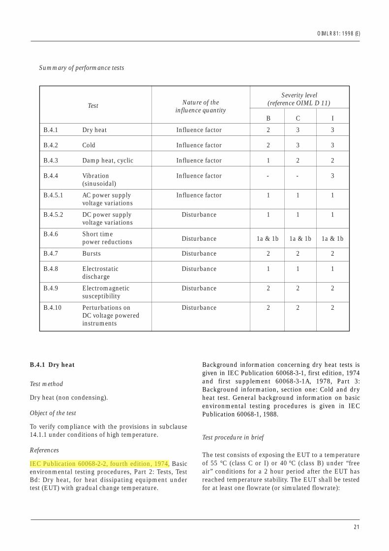
Test Nature of the Severity level
influence quantity(reference OIML D 11)
B C I
B.4.1 Dry heat Influence factor 2 3 3
B.4.2 Cold Influence factor 2 3 3
B.4.3 Damp heat, cyclic Influence factor 1 2 2
B.4.4 Vibration Influence factor - - 3(sinusoidal)
B.4.5.1 AC power supply Influence factor 1 1 1voltage variations
B.4.5.2 DC power supply Disturbance 1 1 1voltage variations
B.4.6 Short timeDisturbance 1a & 1b 1a & 1b 1a & 1bpower reductions
B.4.7 Bursts Disturbance 2 2 2
B.4.8 Electrostatic Disturbance 1 1 1discharge
B.4.9 Electromagnetic Disturbance 2 2 2susceptibility
B.4.10 Perturbations on Disturbance 2 2 2DC voltage powered instruments
Summary of performance tests
air” conditions for a 2 hour period after the EUT hasreached temperature stability. The EUT shall be testedfor at least one flowrate (or simulated flowrate):
• at the reference temperature of 20 °C following con-ditioning;
• at a temperature of –25 °C or –10 °C, 2 hours follow-ing temperature stabilization;
• after recovery of the EUT at the reference temper-ature of 20 °C.
Test severity
1) Temperature: severity level 2: –10 °C;severity level 3: –25 °C.
2) Duration: 2 hours.
Number of test cycles
One cycle.
Maximum allowable variations
All functions shall operate as designed.
All indications shall be within the maximum permiss-ible errors.
B.4.3 Damp heat, cyclic
Test method
Damp heat, cyclic (condensing).
Object of the test
To verify compliance of the electronic measuring ins-trument with the provisions in subclause 14.1.1 underconditions of high humidity when combined withcyclic temperature changes.
References
IEC Publication 60068-2-30, second edition, 1980,Basic environmental testing procedures, Part 2: Tests,test Db: Damp heat, cyclic (12 h + 12 h cycle), testvariant 2.
Background information concerning damp heat testsis given in IEC Publication 60068-2-28, third edition,1990: Guidance for damp heat tests.
OIML R 81: 1998 (E)
• at the reference temperature of 20 °C followingconditioning;
• at the temperature of 55 °C (class C or I) or 40 °C(class B), 2 hours following temperature stabilization;
• after recovery of the EUT at the reference temper-ature of 20 °C.
Test severity
1) Temperature: severity level 2: 40 °Cseverity level 3: 55 °C
2) Duration: 2 hours.
Number of test cycles
One cycle.
Maximum allowable variations
All functions shall operate as designed.
All indications shall be within the maximum permiss-ible errors.
B.4.2 Cold
Test method
Cold.
Object of the test
To verify compliance with the provisions in subclause14.1.1 under conditions of low temperature.
References
IEC Publication 60068-2-1, 1990, Basic environmentaltesting procedures, Part 2: Tests, Test A: Cold,Section 3 - Test Ad: Cold for heat dissipating EUT withgradual change of temperature.
Background information concerning cold tests is givenin IEC Publication 60068-3-1, first edition 1974 andfirst supplement 60068-3-1A, 1978 Part 3: Backgroundinformation, section one: Cold and dry heat tests.General background information on basic environ-mental testing procedures is given in IEC Publication60068-1, 1988.
Test procedure in brief
The test consists of exposing the EUT to a temperatureof –25 °C (class C or I) or –10 °C (class B) under “free
22
OIML R 81: 1998 (E)
23
Test procedure in brief
The non-operational EUT shall be tested by sweepingthe frequency in the specified frequency range, at 1octave/minute, at the specified acceleration level witha specified number of sweep cycles per axis. The EUTshall be tested in its three, mutually perpendicularmain axes, mounted on a rigid fixture by its normalmounting means. It shall normally be mounted so thatthe gravitational force acts in the same direction as itwould in normal use. After the vibration test, a per-formance test under reference conditions for at leastone flowrate is conducted.
Test severity
1) Frequency range: 10 Hz–150 Hz.2) Max. acceleration level: 20 m⋅s2.
Number of test cycles
20 sweep cycles per axis.
Maximum allowable variations
All functions shall operate as designed.
All indications shall be within the maximum permiss-ible errors.
B.4.5 Power voltage variation
B.4.5.1 AC power supply
Test method
Variation in AC mains power supply (single phase).
Object of the test
To verify compliance with the provisions in subclause14.1.1 under conditions of varying AC mains powersupply.
Test procedure in brief
The test consists of exposing the EUT to power voltagevariations, while the EUT is operating under normalatmospheric conditions. The EUT shall be tested for atleast one flowrate (or simulated flowrate), at the upperand lower voltage limits.
Test procedure in brief
The test consists of exposing the non-operational EUT(power supplied and on) to cyclic temperature varia-tions between 25 °C and the upper temperature of55 °C (class C or I) or 40 °C (class B), maintaining therelative humidity above 95 % during the temperaturechanges and during the phases at low temperature,and at 93 % at the upper temperature phases. Conden-sation should occur on the EUT during the temper-ature rise. The standard atmospheric stabilizing periodbefore and recovery after the cyclic exposure areindicated in IEC Publication 60068-2-30. Afterrecovery, a performance test under reference conditionsfor at least one flowrate (or simulated flowrate) isconducted.
Test severity
1) Upper temperature: severity level 1: 40 °C;severity level 2: 55 °C.
2) Humidity: > 93 %.3) Duration: 24 hours.
Number of test cycles
Two cycles.
Maximum allowable variations
All functions shall operate as designed.
All indications shall be within the maximum permiss-ible errors.
B.4.4 Vibration
Test method
Sinusoidal vibration.
Object of the test
To verify compliance of the electronic measuringinstrument to the provisions in subclause 14.1.1 underconditions of sinusoidal vibration.
References
IEC Publication 60068-2-6, 1995, Basic environmentaltesting procedures, Part 2: Tests. Test Fc: Vibration(sinusoidal).
OIML R 81: 1998 (E)
24
Test severity
Mains voltage: upper limit: Unom + 10 %;lower limit: Unom – 15 %.
Number of test cycles
One cycle.
Maximum allowable variations
All functions shall operate as designed.
All indications shall be within the maximum permiss-ible errors.
B.4.5.2 DC power supply
Test method
Variation in DC power supply.
Object of the test
To verify compliance with the provisions subclause14.1.1 under conditions of varying DC power supply.
Test procedure in brief
The test consists of exposing the EUT to power voltagevariations, while the EUT is operating under normalatmospheric conditions. The EUT shall be tested atleast one flowrate (or simulated flowrate), at the upperand lower voltage limits
Test severity
DC voltage: upper limit: Unom + 10 %;lower limit: Unom – 15 %.
Number of test cycles
One cycle.
Maximum allowable variations
All functions shall operate as designed.
All indications shall be within the maximum permiss-ible errors.
B.4.6 Short time power reduction (not applicableto systems with a DC power supply)
Test method
Short time interruptions and reductions of mainsvoltage.
Object of the test
To verify compliance with the provisions in subclause14.1.1 under conditions of short time mains voltageinterruptions and reductions.
References
IEC Publication 61000-4-11 (1994), Electromagneticcompatibility (EMC) Part 4: Testing and measurementtechniques - Section 11. Voltage dips, short inter-ruptions and voltage variations immunity tests.Section 5.2 (Test levels - Voltage variation). Section8.2.2 (Execution of the test-voltage variation).
Test procedure in brief
The test consists of subjecting the EUT to voltageinterruptions from nominal voltage to zero voltage fora duration equal to 10 ms, and from nominal voltageto 50 % of nominal for a duration equal to 20 ms. Themains voltage interruptions and reductions shall berepeated ten times with a time interval of at least 10seconds. The EUT shall be tested for at least one flow-rate (or simulated flowrate).
Test severity
100 % voltage interruption for a period equal to 10 ms;50 % voltage reduction for a period equal to 20 ms.
Number of test cycles
Ten tests with a minimum of 10 seconds between tests.
Maximum allowable variations
a) For interruptible measuring systems, either thedifference between the quantity indication duringthe test and the indication under reference con-ditions shall not exceed the values given in 3.24 orthe measuring system shall detect and act upon asignificant fault, in compliance with subclause14.1.1.
b) For non-interruptible measuring systems, thedifference between the quantity indication duringthe test and the indication under reference con-ditions shall not exceed the values given in 3.24.
OIML R 81: 1998 (E)
25
B.4.7 Bursts (not applicable to systems with a DCpower supply)
Test method
Electrical bursts.
Object of the test
To verify compliance with the provisions in subclause14.1.1 under conditions where electrical bursts aresuperimposed on the mains voltage.
References
IEC Publication 61000-4-4 (1995), Electromagneticcompatibility (EMC) Part 4: Testing and measurementtechniques - Section 4: Electrical fast transient/burstimmunity test. Basic EMC publication.
Test procedure in brief
The test consists of subjecting the EUT to bursts ofdouble exponential wave-form transient voltages. Eachspike shall have a rise time of 5 ns and a half amp-litude duration of 50 ns. The burst length shall be15 ms, the burst period (repetition time interval) shallbe 300 ms. All these bursts shall be applied during thesame measurement or simulated measurement.
Test severity
Amplitude (peak value) 1000 V.
Number of test cycles
At least 10 positive and 10 negative randomly phasedbursts shall be applied at 1000 V.
Maximum allowable variations
a) For interruptible measuring systems, either thedifference between the quantity indication duringthe test and the indication under reference con-ditions shall not exceed the values given in 3.24 orthe measuring system shall detect and act upon asignificant fault, in compliance with subclause14.1.1.
b) For non-interruptible measuring systems, thedifference between the quantity indication duringthe test and the indication under reference con-ditions shall not exceed the values given in 3.24.
B.4.8 Electrostatic discharge
Test method
Electrostatic discharge (ESD).
Object of the test
To verify compliance with the provisions in subclause14.1.1 under conditions of electrostatic discharges.
References
IEC Publication 61000-4-2 (1995) Electromagneticcompatibility (EMC) Part 4: Testing and measurementtechniques - Section 2: Electrostatic dischargeimmunity test. Basic EMC Publication.
Test procedure in brief
A capacitor of 150 pF is charged by a suitable DCvoltage source. The capacitor is then dischargedthrough the EUT by connecting one terminal toground (chassis) and the other via 150 ohms tosurfaces which are normally accessible to the operator.
In the case of contact discharges, the tip of the dis-charge electrode shall touch the EUT before thedischarge switch is operated.
In the case of painted surfaces covering a conductingsubstrate, the following procedure shall be adopted:
If the coating is not declared to be an insulatingcoating by the instrument manufacturer, then thepoint tip of the generator shall penetrate the coatingso as to make contact with the conducting substrate.Coating declared as insulating by the manufacturershall only be submitted to the air discharge. Thecontact discharge test shall not be applied to suchsurfaces.
In the case of air discharges, the round discharge tipof the discharge electrode shall be approached as fastas possible (without causing mechanical damage) totouch the EUT. After each discharge, the ESD gen-erator (discharge electrode) shall be removed from theEUT. The generator is then retriggered for a new singledischarge. This procedure shall be repeated until thedischarges are completed. In the case of an air dis-charge test, the discharge switch which is used forcontact discharge, shall be closed.
Test severity
Air discharge: up to and including 8 kV;Contact discharge: up to and including 6 kV.
If antennae with circular polarization, i.e. log-spiral orhelical antennae are used to generate the electromag-netic field, a change in the position of the antennae isnot necessary.
When the test is carried out in a shielded enclosure, tocomply with international law prohibiting interferenceto radio communications, anechoic shielding may benecessary to reduce reflection from the walls.
Test severity
Frequency range 26 MHz–1000 MHzField strength 3 V/mModulation 80 %, 1 kHz sine wave
Maximum allowable variations
a) For interruptible measuring systems, either thedifference between the quantity indication duringthe test and the indication under reference con-ditions shall not exceed the values given in 3.24 orthe measuring system shall detect and act upon asignificant fault, in compliance with subclause14.1.1.
b) For non-interruptible measuring systems, thedifference between the quantity indication duringthe test and the indication under reference con-ditions shall not exceed the values given in 3.24.
B.4.10 Perturbations on DC voltage poweredinstruments
Electronic measuring systems with DC voltage powersupply shall not be subjected to the tests B.4.5.1 ACpower supply, B.4.6 Short time power reduction, andB.4.7 Bursts. They shall meet the following:
1 General
When the power supplied is less than –15 % Unom, orgreater than +10 % Unom, during a measurement theEUT shall either indicate within mpe or not provide anindication that could be construed as measurementvalue.
2 For instruments powered by the battery of a vehicle
Test pulses 1, 2, and 3 as specified in ISO 7637: Roadvehicles. Electrical disturbance by conduction andcoupling, Part 1 or Part 2 as appropriate shall beeffected. The pulses are to be repeated for as long asnecessary to complete the test.
The pattern approval certificate shall indicate at leastSeverity Level II.
OIML R 81: 1998 (E)
Number of test cyclesAt least ten discharges shall be applied at intervals ofat least 10 seconds between discharges, during thesame measurement or simulated measurement.
Maximum allowable variationsa) For interruptible measuring systems, either the
difference between the quantity indication duringthe test and the indication under reference con-ditions shall not exceed the values given in 3.24 orthe measuring system shall detect and act upon asignificant fault, in compliance with subclause14.1.1.
b) For non-interruptible measuring systems, thedifferences between the quantity indication duringthe test and the indication under reference con-ditions shall not exceed the values given in 3.24.
B.4.9 Electromagnetic susceptibility
Test methodElectromagnetic fields (radiated).
Object of the testTo verify compliance with the provisions in subclause14.1.1 under various electromagnetic fields.
ReferencesIEC Publication 61000-4-3 (1995) Electromagneticcompatibility (EMC) Part 4: Testing and measurementtechniques - Section 3: Radiated, radio-frequency,electromagnetic field immunity test.
Test procedure in briefThe EUT shall be exposed to an electromagnetic fieldstrength as specified by the severity level during themeasurement or simulated measurement. The fieldstrength can be generated in the following ways:
• the strip line is used at frequencies below 30 MHz(in some cases 150 MHz) for smaller EUT’s;
• the long wire is used at frequencies below 30 MHzfor larger EUT’s;
• dipole antennae or antennae with circular polariza-tion placed 1 m from the EUT are used at highfrequencies.
The specified field strength is established prior totesting (without the EUT in the field).
The field is generated in two orthogonal polarizationsand the frequency range is scanned slowly.
26
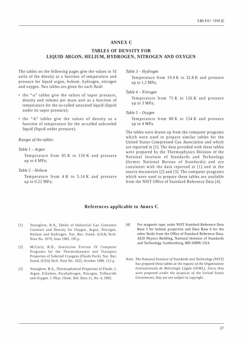
OIML R 81: 1998 (E)
27
ANNEX C
TABLES OF DENSITY FORLIQUID ARGON, HELIUM, HYDROGEN, NITROGEN AND OXYGEN
The tables on the following pages give the values in SIunits of the density as a function of temperature andpressure for liquid argon, helium, hydrogen, nitrogenand oxygen. Two tables are given for each fluid:
• the “-a” tables give the values of vapor pressure,density and volume per mass unit as a function oftemperature for the so-called saturated liquid (liquidunder its vapor pressure);
• the “-b” tables give the values of density as afunction of temperature for the so-called subcooledliquid (liquid under pressure).
Ranges of the tables:
Table 1 – Argon
Temperature from 85 K to 150 K and pressureup to 4 MPa;
Table 2 – Helium
Temperature from 4 K to 5.14 K and pressure up to 0.22 MPa;
Table 3 – HydrogenTemperature from 19.4 K to 32.8 K and pressure up to 1.2 MPa;
Table 4 – NitrogenTemperature from 75 K to 126 K and pressure up to 3 MPa;
Table 5 – OxygenTemperature from 88 K to 154 K and pressure up to 4 MPa.
The tables were drawn up from the computer programswhich were used to prepare similar tables for theUnited States Compressed Gas Association and whichare reported in [1]. The data provided with these tableswere prepared by the Thermophysics Division of theNational Institute of Standards and Technology(former National Bureau of Standards) and areconsistent with the data reported in [1] and in thesource documents [2] and [3]. The computer programswhich were used to prepare these tables are availablefrom the NIST Office of Standard Reference Data [4].
References applicable to Annex C
[1] Younglove, B.A., Tables of Industrial Gas ContainerContents and Density for Oxygen, Argon, Nitrogen,Helium and Hydrogen. Nat. Bur. Stand. (USA) Tech.Note No. 1079, June 1985. 195 p.
[2] McCarty, R.D., Interactive Fortran IV ComputerPrograms for the Thermodynamic and TransportProperties of Selected Cryogens (Fluids Pack). Nat. Bur.Stand. (USA) Tech. Note No. 1025, October 1980. 112 p.
[3] Younglove, B.A., Thermophysical Properties of Fluids. I.Argon, Ethylene, Parahydrogen, Nitrogen, Trifluorideand Oxygen. J. Phys. Chem. Ref. Data 11, No. 4, 1982.
[4] For magnetic tape, order NIST Standard Reference DataBase 5 for helium properties and Data Base 6 for theother fluids from the Office of Standard Reference Data,A320 Physics Building, National Institute of Standardsand Technology, Gaithersburg, MD 20899, USA.
Note: The National Institute of Standards and Technology (NIST)has prepared these tables at the request of the OrganisationInternationale de Métrologie Légale (OIML). Since theywere prepared under the auspices of the United StatesGovernment, they are not subject to copyright.
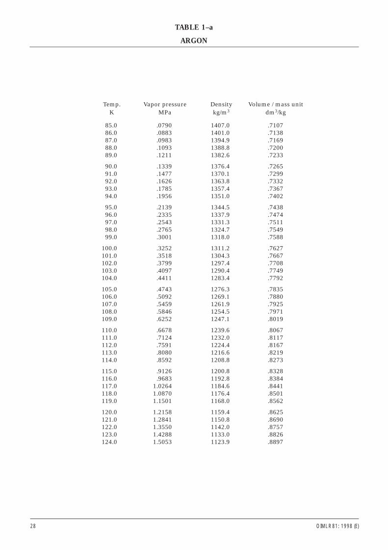
Temp. Vapor pressure Density Volume / mass unitK MPa kg/m3 dm3/kg
85.0 .0790 1407.0 .710786.0 .0883 1401.0 .713887.0 .0983 1394.9 .716988.0 .1093 1388.8 .720089.0 .1211 1382.6 .7233
90.0 .1339 1376.4 .726591.0 .1477 1370.1 .729992.0 .1626 1363.8 .733293.0 .1785 1357.4 .736794.0 .1956 1351.0 .7402
95.0 .2139 1344.5 .743896.0 .2335 1337.9 .747497.0 .2543 1331.3 .751198.0 .2765 1324.7 .754999.0 .3001 1318.0 .7588
100.0 .3252 1311.2 .7627101.0 .3518 1304.3 .7667102.0 .3799 1297.4 .7708103.0 .4097 1290.4 .7749104.0 .4411 1283.4 .7792
105.0 .4743 1276.3 .7835106.0 .5092 1269.1 .7880107.0 .5459 1261.9 .7925108.0 .5846 1254.5 .7971109.0 .6252 1247.1 .8019
110.0 .6678 1239.6 .8067111.0 .7124 1232.0 .8117112.0 .7591 1224.4 .8167113.0 .8080 1216.6 .8219114.0 .8592 1208.8 .8273
115.0 .9126 1200.8 .8328116.0 .9683 1192.8 .8384117.0 1.0264 1184.6 .8441118.0 1.0870 1176.4 .8501119.0 1.1501 1168.0 .8562
120.0 1.2158 1159.4 .8625121.0 1.2841 1150.8 .8690122.0 1.3550 1142.0 .8757123.0 1.4288 1133.0 .8826124.0 1.5053 1123.9 .8897
28 OIML R 81: 1998 (E)
TABLE 1–a
ARGON
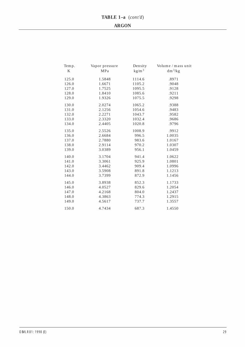
OIML R 81: 1998 (E) 29
Temp. Vapor pressure Density Volume / mass unitK MPa kg/m3 dm3/kg
125.0 1.5848 1114.6 .8971126.0 1.6671 1105.2 .9048127.0 1.7525 1095.5 .9128128.0 1.8410 1085.6 .9211129.0 1.9326 1075.5 .9298
130.0 2.0274 1065.2 .9388131.0 2.1256 1054.6 .9483132.0 2.2271 1043.7 .9582133.0 2.3320 1032.4 .9686134.0 2.4405 1020.8 .9796
135.0 2.5526 1008.9 .9912136.0 2.6684 996.5 1.0035137.0 2.7880 983.6 1.0167138.0 2.9114 970.2 1.0307139.0 3.0389 956.1 1.0459
140.0 3.1704 941.4 1.0622141.0 3.3061 925.9 1.0801142.0 3.4462 909.4 1.0996143.0 3.5908 891.8 1.1213144.0 3.7399 872.9 1.1456
145.0 3.8938 852.3 1.1733146.0 4.0527 829.6 1.2054147.0 4.2168 804.0 1.2437148.0 4.3863 774.3 1.2915149.0 4.5617 737.7 1.3557
150.0 4.7434 687.3 1.4550
TABLE 1–a (cont’d)
ARGON
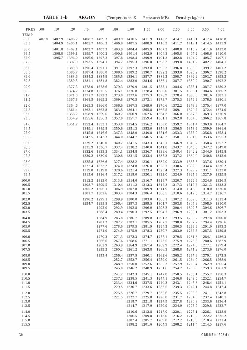
PRES .08 .10 .20 .40 .60 .80 1.00 1.50 2.00 2.50 3.00 3.50 4.00
TEMP85.0 1407.8 1407.9 1408.2 1408.7 1409.3 1409.9 1410.5 1411.9 1413.3 1414.7 1416.1 1417.4 1418.885.5 1404.9 1405.1 1405.7 1406.3 1406.9 1407.5 1408.9 1410.3 1411.7 1413.1 1414.5 1415.9
86.0 1401.8 1402.1 1402.7 1403.3 1403.9 1404.4 1405.9 1407.3 1408.8 1410.2 1411.6 1413.086.5 1398.8 1399.1 1399.7 1400.2 1400.8 1401.4 1402.9 1404.3 1405.8 1407.2 1408.6 1410.087.0 1395.7 1396.0 1396.6 1397.2 1397.8 1398.4 1399.9 1401.3 1402.8 1404.2 1405.7 1407.187.5 1392.9 1393.5 1394.1 1394.7 1395.3 1396.8 1398.3 1399.8 1401.2 1402.7 1404.1
88.0 1389.8 1390.4 1391.1 1391.7 1392.3 1393.8 1395.3 1396.8 1398.3 1399.7 1401.288.5 1386.7 1387.4 1388.0 1388.6 1389.2 1390.7 1392.2 1393.8 1395.2 1396.7 1398.289.0 1383.6 1384.2 1384.9 1385.5 1386.1 1387.7 1389.2 1390.7 1392.2 1393.7 1395.289.5 1380.5 1381.1 1381.8 1382.4 1383.0 1384.6 1386.1 1387.7 1389.2 1390.7 1392.2
90.0 1377.3 1378.0 1378.6 1379.3 1379.9 1381.5 1383.1 1384.6 1386.1 1387.7 1389.290.5 1374.2 1374.8 1375.5 1376.1 1376.8 1378.4 1380.0 1381.5 1383.1 1384.6 1386.291.0 1371.0 1371.7 1372.3 1373.0 1373.6 1375.3 1376.9 1378.4 1380.0 1381.6 1383.191.5 1367.8 1368.5 1369.2 1369.8 1370.5 1372.1 1373.7 1375.3 1376.9 1378.5 1380.1
92.0 1364.6 1365.3 1366.0 1366.6 1367.3 1369.0 1370.6 1372.2 1373.8 1375.4 1377.092.5 1361.4 1362.1 1362.8 1363.5 1364.1 1365.8 1367.5 1369.1 1370.7 1372.4 1374.093.0 1358.2 1358.9 1359.6 1360.2 1360.9 1362.6 1364.3 1366.0 1367.6 1369.3 1370.993.5 1354.9 1355.6 1356.3 1357.0 1357.7 1359.4 1361.1 1362.8 1364.5 1366.2 1367.8
94.0 1351.7 1352.4 1353.1 1353.8 1354.5 1356.2 1358.0 1359.7 1361.4 1363.0 1364.794.5 1349.1 1349.8 1350.6 1351.3 1353.0 1354.8 1356.5 1358.2 1359.9 1361.695.0 1345.8 1346.6 1347.3 1348.0 1349.8 1351.6 1353.3 1355.0 1356.8 1358.495.5 1342.5 1343.3 1344.0 1344.7 1346.5 1348.3 1350.1 1351.9 1353.6 1355.3
96.0 1339.2 1340.0 1340.7 1341.5 1343.3 1345.1 1346.9 1348.7 1350.4 1352.296.5 1335.9 1336.7 1337.4 1338.2 1340.0 1341.8 1343.7 1345.5 1347.2 1349.097.0 1332.6 1333.3 1334.1 1334.8 1336.7 1338.6 1340.4 1342.2 1344.0 1345.897.5 1329.2 1330.0 1330.8 1331.5 1333.4 1335.3 1337.2 1339.0 1340.8 1342.6
98.0 1325.8 1326.6 1327.4 1328.2 1330.1 1332.0 1333.9 1335.8 1337.6 1339.498.5 1322.4 1323.2 1324.0 1324.8 1326.8 1328.7 1330.6 1332.5 1334.4 1336.299.0 1319.0 1319.8 1320.6 1321.4 1323.4 1325.4 1327.3 1329.2 1331.1 1333.099.5 1315.6 1316.4 1317.2 1318.0 1320.1 1322.0 1324.0 1325.9 1327.9 1329.8
100.0 1312.2 1313.0 1313.8 1314.6 1316.7 1318.7 1320.7 1322.6 1324.6 1326.5100.5 1308.7 1309.5 1310.4 1311.2 1313.3 1315.3 1317.3 1319.3 1321.3 1323.2101.0 1305.2 1306.1 1306.9 1307.8 1309.9 1311.9 1314.0 1316.0 1318.0 1320.0101.5 1301.7 1302.6 1303.4 1304.3 1306.4 1308.5 1310.6 1312.6 1314.7 1316.7
102.0 1298.2 1299.1 1299.9 1300.8 1303.0 1305.1 1307.2 1309.3 1311.3 1313.4102.5 1294.7 1295.5 1296.4 1297.3 1299.5 1301.7 1303.8 1305.9 1308.0 1310.0103.0 1292.0 1292.9 1293.8 1296.0 1298.2 1300.4 1302.5 1304.6 1306.7103.5 1288.4 1289.4 1290.3 1292.5 1294.7 1296.9 1299.1 1301.2 1303.3
104.0 1284.9 1285.8 1286.7 1289.0 1291.3 1293.5 1295.7 1297.8 1300.0104.5 1281.2 1282.2 1283.1 1285.5 1287.7 1290.0 1292.2 1294.4 1296.6105.0 1277.6 1278.6 1279.5 1281.9 1284.2 1286.5 1288.8 1291.0 1293.2105.5 1274.0 1274.9 1275.9 1278.3 1280.7 1283.0 1285.3 1287.5 1289.8
106.0 1270.3 1271.3 1272.3 1274.7 1277.1 1279.5 1281.8 1284.1 1286.3106.5 1266.6 1267.6 1268.6 1271.1 1273.5 1275.9 1278.3 1280.6 1282.9107.0 1262.9 1263.9 1264.9 1267.4 1269.9 1272.4 1274.8 1277.1 1279.4107.5 1259.2 1260.2 1261.2 1263.8 1266.3 1268.8 1271.2 1273.6 1276.0
108.0 1255.4 1256.4 1257.5 1260.1 1262.6 1265.2 1267.6 1270.1 1272.5108.5 1252.7 1253.7 1256.4 1259.0 1261.5 1264.0 1266.5 1268.9109.0 1248.9 1250.0 1252.6 1255.3 1257.9 1260.4 1262.9 1265.4109.5 1245.0 1246.2 1248.9 1251.6 1254.2 1256.8 1259.3 1261.9
110.0 1241.2 1242.3 1245.1 1247.8 1250.5 1253.1 1255.7 1258.3110.5 1237.3 1238.5 1241.3 1244.1 1246.8 1249.5 1252.1 1254.7111.0 1233.4 1234.6 1237.5 1240.3 1243.1 1245.8 1248.4 1251.1111.5 1229.5 1230.7 1233.6 1236.5 1239.3 1242.1 1244.8 1247.4
112.0 1225.5 1226.7 1229.7 1232.6 1235.5 1238.3 1241.1 1243.8112.5 1221.5 1222.7 1225.8 1228.8 1231.7 1234.5 1237.4 1240.1113.0 1218.7 1221.8 1224.9 1227.8 1230.8 1233.6 1236.4113.5 1214.7 1217.9 1220.9 1224.0 1226.9 1229.8 1232.7
114.0 1210.6 1213.8 1217.0 1220.1 1223.1 1226.1 1228.9114.5 1206.5 1209.8 1213.0 1216.2 1219.2 1222.2 1225.2115.0 1202.4 1205.7 1209.0 1212.2 1215.3 1218.4 1221.4115.5 1198.2 1201.6 1204.9 1208.2 1211.4 1214.5 1217.6
30 OIML R 81: 1998 (E)
TABLE 1–b ARGON (Temperature: K Pressure: MPa Density: kg/m3)
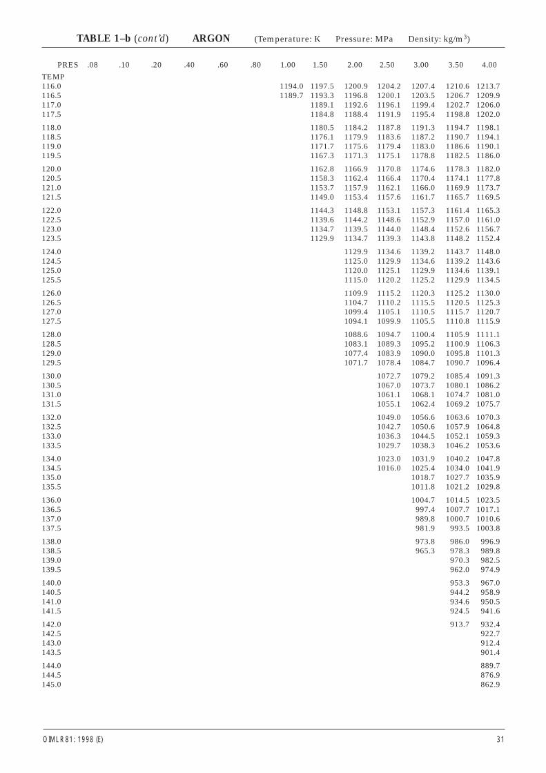
PRES .08 .10 .20 .40 .60 .80 1.00 1.50 2.00 2.50 3.00 3.50 4.00
TEMP116.0 1194.0 1197.5 1200.9 1204.2 1207.4 1210.6 1213.7116.5 1189.7 1193.3 1196.8 1200.1 1203.5 1206.7 1209.9117.0 1189.1 1192.6 1196.1 1199.4 1202.7 1206.0117.5 1184.8 1188.4 1191.9 1195.4 1198.8 1202.0
118.0 1180.5 1184.2 1187.8 1191.3 1194.7 1198.1118.5 1176.1 1179.9 1183.6 1187.2 1190.7 1194.1119.0 1171.7 1175.6 1179.4 1183.0 1186.6 1190.1119.5 1167.3 1171.3 1175.1 1178.8 1182.5 1186.0
120.0 1162.8 1166.9 1170.8 1174.6 1178.3 1182.0120.5 1158.3 1162.4 1166.4 1170.4 1174.1 1177.8121.0 1153.7 1157.9 1162.1 1166.0 1169.9 1173.7121.5 1149.0 1153.4 1157.6 1161.7 1165.7 1169.5
122.0 1144.3 1148.8 1153.1 1157.3 1161.4 1165.3122.5 1139.6 1144.2 1148.6 1152.9 1157.0 1161.0123.0 1134.7 1139.5 1144.0 1148.4 1152.6 1156.7123.5 1129.9 1134.7 1139.3 1143.8 1148.2 1152.4
124.0 1129.9 1134.6 1139.2 1143.7 1148.0124.5 1125.0 1129.9 1134.6 1139.2 1143.6125.0 1120.0 1125.1 1129.9 1134.6 1139.1125.5 1115.0 1120.2 1125.2 1129.9 1134.5
126.0 1109.9 1115.2 1120.3 1125.2 1130.0126.5 1104.7 1110.2 1115.5 1120.5 1125.3127.0 1099.4 1105.1 1110.5 1115.7 1120.7127.5 1094.1 1099.9 1105.5 1110.8 1115.9
128.0 1088.6 1094.7 1100.4 1105.9 1111.1128.5 1083.1 1089.3 1095.2 1100.9 1106.3129.0 1077.4 1083.9 1090.0 1095.8 1101.3129.5 1071.7 1078.4 1084.7 1090.7 1096.4
130.0 1072.7 1079.2 1085.4 1091.3130.5 1067.0 1073.7 1080.1 1086.2131.0 1061.1 1068.1 1074.7 1081.0131.5 1055.1 1062.4 1069.2 1075.7
132.0 1049.0 1056.6 1063.6 1070.3132.5 1042.7 1050.6 1057.9 1064.8133.0 1036.3 1044.5 1052.1 1059.3133.5 1029.7 1038.3 1046.2 1053.6
134.0 1023.0 1031.9 1040.2 1047.8134.5 1016.0 1025.4 1034.0 1041.9135.0 1018.7 1027.7 1035.9135.5 1011.8 1021.2 1029.8
136.0 1004.7 1014.5 1023.5136.5 997.4 1007.7 1017.1137.0 989.8 1000.7 1010.6137.5 981.9 993.5 1003.8
138.0 973.8 986.0 996.9138.5 965.3 978.3 989.8139.0 970.3 982.5139.5 962.0 974.9
140.0 953.3 967.0140.5 944.2 958.9141.0 934.6 950.5141.5 924.5 941.6
142.0 913.7 932.4142.5 922.7143.0 912.4143.5 901.4
144.0 889.7144.5 876.9145.0 862.9
OIML R 81: 1998 (E) 31
TABLE 1–b (cont’d) ARGON (Temperature: K Pressure: MPa Density: kg/m3)
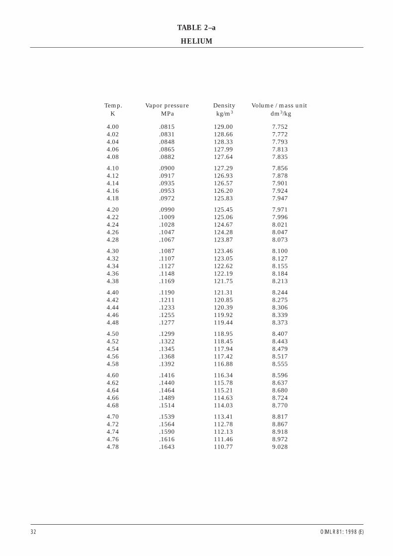
Temp. Vapor pressure Density Volume / mass unitK MPa kg/m3 dm3/kg
4.00 .0815 129.00 7.7524.02 .0831 128.66 7.7724.04 .0848 128.33 7.7934.06 .0865 127.99 7.8134.08 .0882 127.64 7.835
4.10 .0900 127.29 7.8564.12 .0917 126.93 7.8784.14 .0935 126.57 7.9014.16 .0953 126.20 7.9244.18 .0972 125.83 7.947
4.20 .0990 125.45 7.9714.22 .1009 125.06 7.9964.24 .1028 124.67 8.0214.26 .1047 124.28 8.0474.28 .1067 123.87 8.073
4.30 .1087 123.46 8.1004.32 .1107 123.05 8.1274.34 .1127 122.62 8.1554.36 .1148 122.19 8.1844.38 .1169 121.75 8.213
4.40 .1190 121.31 8.2444.42 .1211 120.85 8.2754.44 .1233 120.39 8.3064.46 .1255 119.92 8.3394.48 .1277 119.44 8.373
4.50 .1299 118.95 8.4074.52 .1322 118.45 8.4434.54 .1345 117.94 8.4794.56 .1368 117.42 8.5174.58 .1392 116.88 8.555
4.60 .1416 116.34 8.5964.62 .1440 115.78 8.6374.64 .1464 115.21 8.6804.66 .1489 114.63 8.7244.68 .1514 114.03 8.770
4.70 .1539 113.41 8.8174.72 .1564 112.78 8.8674.74 .1590 112.13 8.9184.76 .1616 111.46 8.9724.78 .1643 110.77 9.028
32 OIML R 81: 1998 (E)
TABLE 2–a
HELIUM
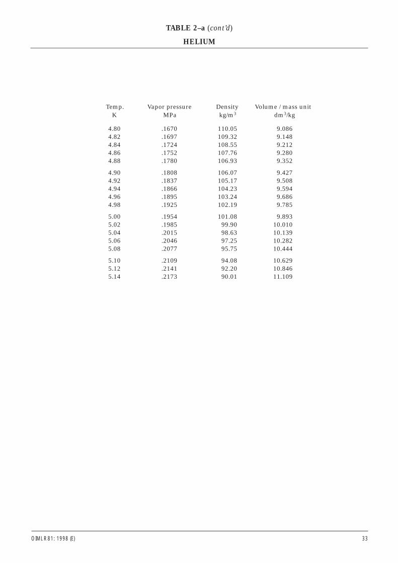
Temp. Vapor pressure Density Volume / mass unitK MPa kg/m3 dm3/kg
4.80 .1670 110.05 9.0864.82 .1697 109.32 9.1484.84 .1724 108.55 9.2124.86 .1752 107.76 9.2804.88 .1780 106.93 9.352
4.90 .1808 106.07 9.4274.92 .1837 105.17 9.5084.94 .1866 104.23 9.5944.96 .1895 103.24 9.6864.98 .1925 102.19 9.785
5.00 .1954 101.08 9.8935.02 .1985 99.90 10.0105.04 .2015 98.63 10.1395.06 .2046 97.25 10.2825.08 .2077 95.75 10.444
5.10 .2109 94.08 10.6295.12 .2141 92.20 10.8465.14 .2173 90.01 11.109
OIML R 81: 1998 (E) 33
TABLE 2–a (cont’d)
HELIUM
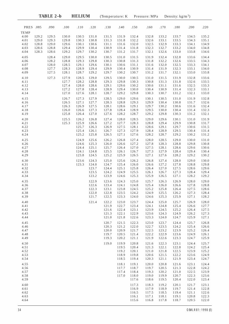
PRES .085 .090 .100 .110 .120 .130 .140 .150 .160 .170 .180 .200 .220
TEMP4.00 129.2 129.5 130.0 130.5 131.0 131.5 131.9 132.4 132.8 133.2 133.7 134.5 135.24.01 129.0 129.3 129.8 130.3 130.8 131.3 131.8 132.2 132.6 133.1 133.5 134.3 135.14.02 128.8 129.0 129.6 130.1 130.6 131.1 131.6 132.0 132.5 132.9 133.3 134.1 134.94.03 128.6 128.8 129.4 129.9 130.4 130.9 131.4 131.8 132.3 132.7 133.2 134.0 134.84.04 128.3 128.6 129.2 129.7 130.2 130.7 131.2 131.7 132.1 132.6 133.0 133.8 134.6
4.05 128.4 129.0 129.5 130.0 130.5 131.0 131.5 131.9 132.4 132.8 133.6 134.44.06 128.2 128.8 129.3 129.8 130.3 130.8 131.3 131.8 132.2 132.6 133.5 134.34.07 128.0 128.5 129.1 129.6 130.1 130.6 131.1 131.6 132.0 132.5 133.3 134.14.08 127.7 128.3 128.9 129.4 129.9 130.4 130.9 131.4 131.9 132.3 133.1 134.04.09 127.5 128.1 128.7 129.2 129.7 130.2 130.7 131.2 131.7 132.1 133.0 133.8
4.10 127.3 127.9 128.5 129.0 129.5 130.0 130.5 131.0 131.5 131.9 132.8 133.64.11 127.7 128.2 128.8 129.3 129.8 130.3 130.8 131.3 131.8 132.6 133.54.12 127.4 128.0 128.6 129.1 129.6 130.2 130.6 131.1 131.6 132.5 133.34.13 127.2 127.8 128.4 128.9 129.4 130.0 130.4 130.9 131.4 132.3 133.14.14 127.0 127.6 128.1 128.7 129.2 129.8 130.3 130.7 131.2 132.1 133.0
4.15 126.7 127.3 127.9 128.5 129.0 129.6 130.1 130.5 131.0 131.9 132.84.16 126.5 127.1 127.7 128.3 128.8 129.3 129.9 130.4 130.8 131.7 132.64.17 126.3 126.9 127.5 128.1 128.6 129.1 129.7 130.2 130.6 131.6 132.44.18 126.0 126.6 127.3 127.8 128.4 128.9 129.5 130.0 130.4 131.4 132.34.19 125.8 126.4 127.0 127.6 128.2 128.7 129.2 129.8 130.3 131.2 132.1
4.20 125.5 126.2 126.8 127.4 128.0 128.5 129.0 129.6 130.1 131.0 131.94.21 125.3 125.9 126.6 127.2 127.7 128.3 128.8 129.4 129.9 130.8 131.74.22 125.7 126.3 126.9 127.5 128.1 128.6 129.1 129.7 130.6 131.54.23 125.4 126.1 126.7 127.3 127.9 128.4 128.9 129.5 130.4 131.44.24 125.2 125.8 126.5 127.1 127.6 128.2 128.7 129.2 130.2 131.2
4.25 124.9 125.6 126.2 126.8 127.4 128.0 128.5 129.0 130.0 131.04.26 124.6 125.3 126.0 126.6 127.2 127.8 128.3 128.8 129.8 130.84.27 124.4 125.1 125.7 126.4 127.0 127.5 128.1 128.6 129.6 130.64.28 124.1 124.8 125.5 126.1 126.7 127.3 127.9 128.4 129.4 130.44.29 123.8 124.5 125.2 125.9 126.5 127.1 127.6 128.2 129.2 130.2
4.30 123.6 124.3 125.0 125.6 126.2 126.8 127.4 128.0 129.0 130.04.31 123.3 124.0 124.7 125.4 126.0 126.6 127.2 127.8 128.8 129.84.32 123.7 124.4 125.1 125.8 126.4 127.0 127.5 128.6 129.64.33 123.5 124.2 124.9 125.5 126.1 126.7 127.3 128.4 129.44.34 123.2 123.9 124.6 125.3 125.9 126.5 127.1 128.2 129.2
4.35 122.9 123.6 124.3 125.0 125.7 126.3 126.9 128.0 129.04.36 122.6 123.4 124.1 124.8 125.4 126.0 126.6 127.8 128.84.37 122.3 123.1 123.8 124.5 125.2 125.8 126.4 127.5 128.64.38 122.0 122.8 123.5 124.2 124.9 125.5 126.2 127.3 128.44.39 121.7 122.5 123.3 124.0 124.6 125.3 125.9 127.1 128.2
4.40 121.4 122.2 123.0 123.7 124.4 125.0 125.7 126.9 128.04.41 121.9 122.7 123.4 124.1 124.8 125.4 126.6 127.74.42 121.6 122.4 123.1 123.9 124.5 125.2 126.4 127.54.43 121.3 122.1 122.9 123.6 124.3 124.9 126.2 127.34.44 121.0 121.8 122.6 123.3 124.0 124.7 125.9 127.1
4.45 120.7 121.5 122.3 123.0 123.7 124.4 125.7 126.84.46 120.3 121.2 122.0 122.7 123.5 124.2 125.4 126.64.47 120.0 120.9 121.7 122.5 123.2 123.9 125.2 126.44.48 119.7 120.5 121.4 122.2 122.9 123.6 124.9 126.14.49 119.3 120.2 121.1 121.9 122.6 123.3 124.7 125.9
4.50 119.0 119.9 120.8 121.6 122.3 123.1 124.4 125.74.51 119.5 120.4 121.3 122.1 122.8 124.2 125.44.52 119.2 120.1 121.0 121.8 122.5 123.9 125.24.53 118.9 119.8 120.6 121.5 122.2 123.6 124.94.54 118.5 119.4 120.3 121.1 121.9 123.4 124.7
4.55 118.1 119.1 120.0 120.8 121.6 123.1 124.44.56 117.7 118.7 119.7 120.5 121.3 122.8 124.24.57 117.4 118.4 119.3 120.2 121.0 122.5 123.94.58 117.0 118.0 119.0 119.9 120.7 122.3 123.64.59 117.6 118.6 119.5 120.4 122.0 123.4
4.60 117.3 118.3 119.2 120.1 121.7 123.14.61 116.9 117.9 118.9 119.7 121.4 122.84.62 116.5 117.5 118.5 119.4 121.1 122.64.63 116.1 117.1 118.1 119.1 120.8 122.34.64 115.6 116.8 117.8 118.7 120.5 122.0
34 OIML R 81: 1998 (E)
TABLE 2–b HELIUM (Temperature: K Pressure: MPa Density: kg/m3)
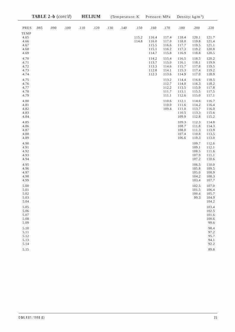
PRES .085 .090 .100 .110 .120 .130 .140 .150 .160 .170 .180 .200 .220
TEMP4.65 115.2 116.4 117.4 118.4 120.1 121.74.66 114.8 116.0 117.0 118.0 119.8 121.44.67 115.5 116.6 117.7 119.5 121.14.68 115.1 116.2 117.3 119.2 120.84.69 114.7 115.8 116.9 118.8 120.5
4.70 114.2 115.4 116.5 118.5 120.24.71 113.7 115.0 116.1 118.1 119.94.72 113.3 114.6 115.7 117.8 119.54.73 112.8 114.1 115.3 117.4 119.24.74 112.3 113.6 114.9 117.0 118.9
4.75 113.2 114.4 116.6 118.54.76 112.7 114.0 116.3 118.24.77 112.2 113.5 115.9 117.84.78 111.7 113.1 115.5 117.54.79 111.1 112.6 115.0 117.1
4.80 110.6 112.1 114.6 116.74.81 110.0 111.6 114.2 116.44.82 109.4 111.0 113.7 116.04.83 110.5 113.3 115.64.84 109.9 112.8 115.2
4.85 109.3 112.3 114.84.86 108.7 111.8 114.34.87 108.0 111.3 113.94.88 107.4 110.8 113.54.89 106.6 110.3 113.0
4.90 109.7 112.64.91 109.1 112.14.92 108.5 111.64.93 107.9 111.14.94 107.2 110.6
4.95 106.5 110.04.96 105.8 109.54.97 105.0 108.94.98 104.2 108.34.99 103.4 107.7
5.00 102.5 107.05.01 101.5 106.45.02 100.4 105.75.03 99.3 104.95.04 104.2
5.05 103.45.06 102.55.07 101.65.08 100.65.09 99.6
5.10 98.45.11 97.25.12 95.75.13 94.15.14 92.2
5.15 89.8
OIML R 81: 1998 (E) 35
TABLE 2–b (cont’d) HELIUM (Temperature: K Pressure: MPa Density: kg/m3)
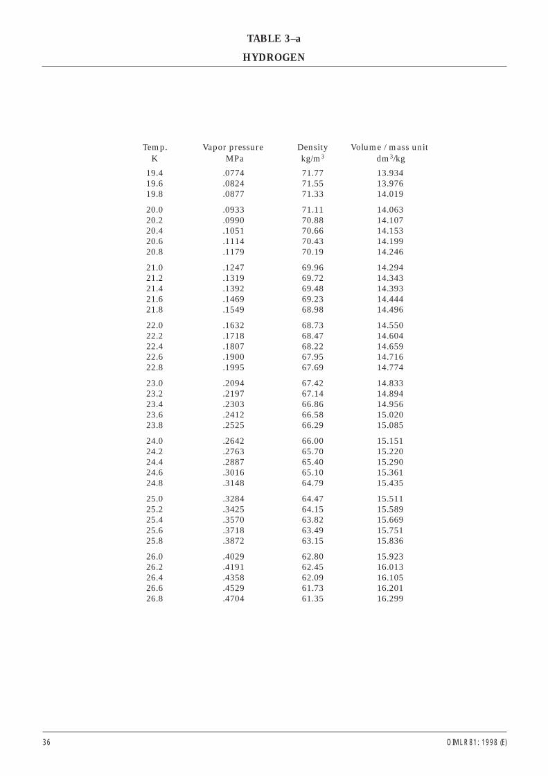
Temp. Vapor pressure Density Volume / mass unitK MPa kg/m3 dm3/kg
19.4 .0774 71.77 13.93419.6 .0824 71.55 13.97619.8 .0877 71.33 14.019
20.0 .0933 71.11 14.06320.2 .0990 70.88 14.10720.4 .1051 70.66 14.15320.6 .1114 70.43 14.19920.8 .1179 70.19 14.246
21.0 .1247 69.96 14.29421.2 .1319 69.72 14.34321.4 .1392 69.48 14.39321.6 .1469 69.23 14.44421.8 .1549 68.98 14.496
22.0 .1632 68.73 14.55022.2 .1718 68.47 14.60422.4 .1807 68.22 14.65922.6 .1900 67.95 14.71622.8 .1995 67.69 14.774
23.0 .2094 67.42 14.83323.2 .2197 67.14 14.89423.4 .2303 66.86 14.95623.6 .2412 66.58 15.02023.8 .2525 66.29 15.085
24.0 .2642 66.00 15.15124.2 .2763 65.70 15.22024.4 .2887 65.40 15.29024.6 .3016 65.10 15.36124.8 .3148 64.79 15.435
25.0 .3284 64.47 15.51125.2 .3425 64.15 15.58925.4 .3570 63.82 15.66925.6 .3718 63.49 15.75125.8 .3872 63.15 15.836
26.0 .4029 62.80 15.92326.2 .4191 62.45 16.01326.4 .4358 62.09 16.10526.6 .4529 61.73 16.20126.8 .4704 61.35 16.299
36 OIML R 81: 1998 (E)
TABLE 3–a
HYDROGEN
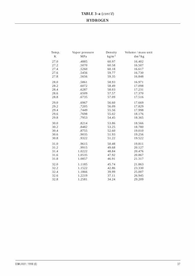
OIML R 81: 1998 (E) 37
Temp. Vapor pressure Density Volume / mass unitK MPa kg/m3 dm3/kg
27.0 .4885 60.97 16.40227.2 .5070 60.58 16.50727.4 .5260 60.18 16.61727.6 .5456 59.77 16.73027.8 .5656 59.35 16.848
28.0 .5861 58.93 16.97128.2 .6072 58.49 17.09828.4 .6287 58.03 17.23128.6 .6509 57.57 17.37028.8 .6735 57.09 17.516
29.0 .6967 56.60 17.66929.2 .7205 56.09 17.82929.4 .7449 55.56 17.99829.6 .7698 55.02 18.17629.8 .7953 54.45 18.365
30.0 .8214 53.86 18.56630.2 .8482 53.25 18.78030.4 .8755 52.60 19.01030.6 .9035 51.93 19.25630.8 .9322 51.22 19.522
31.0 .9615 50.48 19.81131.2 .9915 49.68 20.12731.4 1.0222 48.84 20.47631.6 1.0535 47.92 20.86731.8 1.0857 46.91 21.317
32.0 1.1185 45.74 21.86332.2 1.1522 42.86 23.33032.4 1.1866 39.99 25.00732.6 1.2219 37.11 26.94532.8 1.2581 34.24 29.209
TABLE 3–a (cont’d)
HYDROGEN

38 OIML R 81: 1998 (E)
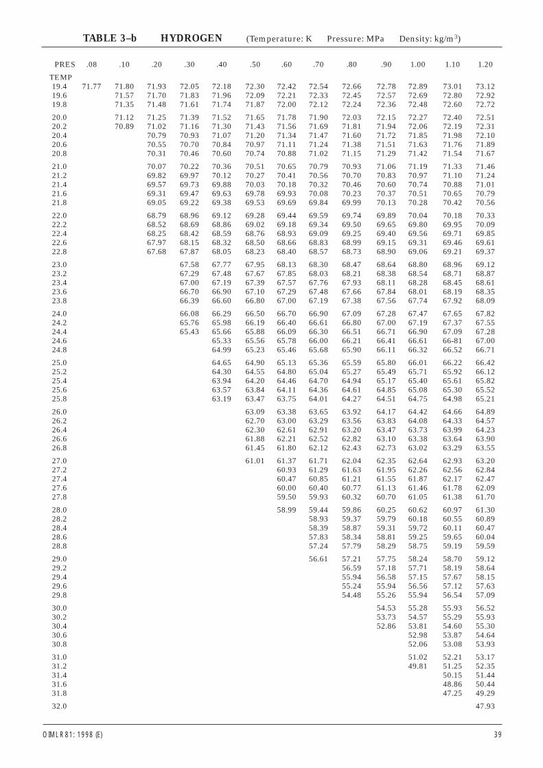
OIML R 81: 1998 (E) 39
PRES .08 .10 .20 .30 .40 .50 .60 .70 .80 .90 1.00 1.10 1.20
TEMP19.4 71.77 71.80 71.93 72.05 72.18 72.30 72.42 72.54 72.66 72.78 72.89 73.01 73.1219.6 71.57 71.70 71.83 71.96 72.09 72.21 72.33 72.45 72.57 72.69 72.80 72.9219.8 71.35 71.48 71.61 71.74 71.87 72.00 72.12 72.24 72.36 72.48 72.60 72.72
20.0 71.12 71.25 71.39 71.52 71.65 71.78 71.90 72.03 72.15 72.27 72.40 72.5120.2 70.89 71.02 71.16 71.30 71.43 71.56 71.69 71.81 71.94 72.06 72.19 72.3120.4 70.79 70.93 71.07 71.20 71.34 71.47 71.60 71.72 71.85 71.98 72.1020.6 70.55 70.70 70.84 70.97 71.11 71.24 71.38 71.51 71.63 71.76 71.8920.8 70.31 70.46 70.60 70.74 70.88 71.02 71.15 71.29 71.42 71.54 71.67
21.0 70.07 70.22 70.36 70.51 70.65 70.79 70.93 71.06 71.19 71.33 71.4621.2 69.82 69.97 70.12 70.27 70.41 70.56 70.70 70.83 70.97 71.10 71.2421.4 69.57 69.73 69.88 70.03 70.18 70.32 70.46 70.60 70.74 70.88 71.0121.6 69.31 69.47 69.63 69.78 69.93 70.08 70.23 70.37 70.51 70.65 70.7921.8 69.05 69.22 69.38 69.53 69.69 69.84 69.99 70.13 70.28 70.42 70.56
22.0 68.79 68.96 69.12 69.28 69.44 69.59 69.74 69.89 70.04 70.18 70.3322.2 68.52 68.69 68.86 69.02 69.18 69.34 69.50 69.65 69.80 69.95 70.0922.4 68.25 68.42 68.59 68.76 68.93 69.09 69.25 69.40 69.56 69.71 69.8522.6 67.97 68.15 68.32 68.50 68.66 68.83 68.99 69.15 69.31 69.46 69.6122.8 67.68 67.87 68.05 68.23 68.40 68.57 68.73 68.90 69.06 69.21 69.37
23.0 67.58 67.77 67.95 68.13 68.30 68.47 68.64 68.80 68.96 69.1223.2 67.29 67.48 67.67 67.85 68.03 68.21 68.38 68.54 68.71 68.8723.4 67.00 67.19 67.39 67.57 67.76 67.93 68.11 68.28 68.45 68.6123.6 66.70 66.90 67.10 67.29 67.48 67.66 67.84 68.01 68.19 68.3523.8 66.39 66.60 66.80 67.00 67.19 67.38 67.56 67.74 67.92 68.09
24.0 66.08 66.29 66.50 66.70 66.90 67.09 67.28 67.47 67.65 67.8224.2 65.76 65.98 66.19 66.40 66.61 66.80 67.00 67.19 67.37 67.5524.4 65.43 65.66 65.88 66.09 66.30 66.51 66.71 66.90 67.09 67.2824.6 65.33 65.56 65.78 66.00 66.21 66.41 66.61 66-81 67.0024.8 64.99 65.23 65.46 65.68 65.90 66.11 66.32 66.52 66.71
25.0 64.65 64.90 65.13 65.36 65.59 65.80 66.01 66.22 66.4225.2 64.30 64.55 64.80 65.04 65.27 65.49 65.71 65.92 66.1225.4 63.94 64.20 64.46 64.70 64.94 65.17 65.40 65.61 65.8225.6 63.57 63.84 64.11 64.36 64.61 64.85 65.08 65.30 65.5225.8 63.19 63.47 63.75 64.01 64.27 64.51 64.75 64.98 65.21
26.0 63.09 63.38 63.65 63.92 64.17 64.42 64.66 64.8926.2 62.70 63.00 63.29 63.56 63.83 64.08 64.33 64.5726.4 62.30 62.61 62.91 63.20 63.47 63.73 63.99 64.2326.6 61.88 62.21 62.52 62.82 63.10 63.38 63.64 63.9026.8 61.45 61.80 62.12 62.43 62.73 63.02 63.29 63.55
27.0 61.01 61.37 61.71 62.04 62.35 62.64 62.93 63.2027.2 60.93 61.29 61.63 61.95 62.26 62.56 62.8427.4 60.47 60.85 61.21 61.55 61.87 62.17 62.4727.6 60.00 60.40 60.77 61.13 61.46 61.78 62.0927.8 59.50 59.93 60.32 60.70 61.05 61.38 61.70
28.0 58.99 59.44 59.86 60.25 60.62 60.97 61.3028.2 58.93 59.37 59.79 60.18 60.55 60.8928.4 58.39 58.87 59.31 59.72 60.11 60.4728.6 57.83 58.34 58.81 59.25 59.65 60.0428.8 57.24 57.79 58.29 58.75 59.19 59.59
29.0 56.61 57.21 57.75 58.24 58.70 59.1229.2 56.59 57.18 57.71 58.19 58.6429.4 55.94 56.58 57.15 57.67 58.1529.6 55.24 55.94 56.56 57.12 57.6329.8 54.48 55.26 55.94 56.54 57.09
30.0 54.53 55.28 55.93 56.5230.2 53.73 54.57 55.29 55.9330.4 52.86 53.81 54.60 55.3030.6 52.98 53.87 54.6430.8 52.06 53.08 53.93
31.0 51.02 52.21 53.1731.2 49.81 51.25 52.3531.4 50.15 51.4431.6 48.86 50.4431.8 47.25 49.29
32.0 47.93
TABLE 3–b HYDROGEN (Temperature: K Pressure: MPa Density: kg/m3)
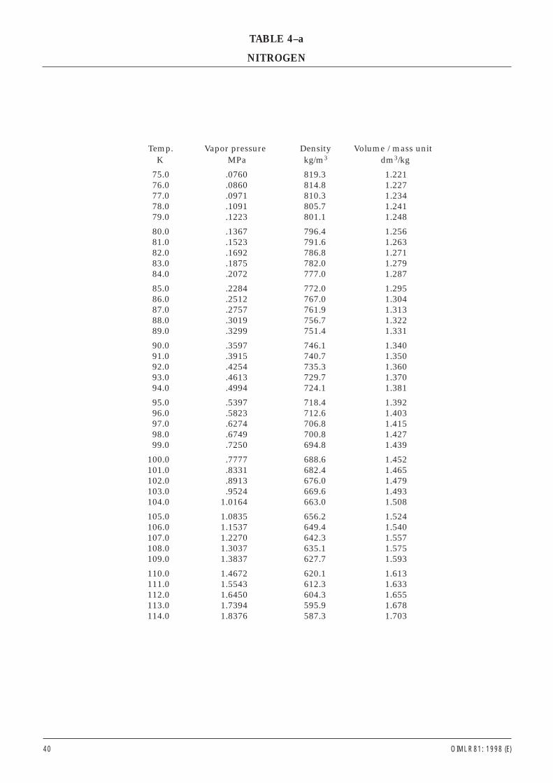
Temp. Vapor pressure Density Volume / mass unitK MPa kg/m3 dm3/kg
75.0 .0760 819.3 1.22176.0 .0860 814.8 1.22777.0 .0971 810.3 1.23478.0 .1091 805.7 1.24179.0 .1223 801.1 1.248
80.0 .1367 796.4 1.25681.0 .1523 791.6 1.26382.0 .1692 786.8 1.27183.0 .1875 782.0 1.27984.0 .2072 777.0 1.287
85.0 .2284 772.0 1.29586.0 .2512 767.0 1.30487.0 .2757 761.9 1.31388.0 .3019 756.7 1.32289.0 .3299 751.4 1.331
90.0 .3597 746.1 1.34091.0 .3915 740.7 1.35092.0 .4254 735.3 1.36093.0 .4613 729.7 1.37094.0 .4994 724.1 1.381
95.0 .5397 718.4 1.39296.0 .5823 712.6 1.40397.0 .6274 706.8 1.41598.0 .6749 700.8 1.42799.0 .7250 694.8 1.439
100.0 .7777 688.6 1.452101.0 .8331 682.4 1.465102.0 .8913 676.0 1.479103.0 .9524 669.6 1.493104.0 1.0164 663.0 1.508
105.0 1.0835 656.2 1.524106.0 1.1537 649.4 1.540107.0 1.2270 642.3 1.557108.0 1.3037 635.1 1.575109.0 1.3837 627.7 1.593
110.0 1.4672 620.1 1.613111.0 1.5543 612.3 1.633112.0 1.6450 604.3 1.655113.0 1.7394 595.9 1.678114.0 1.8376 587.3 1.703
40 OIML R 81: 1998 (E)
TABLE 4–a
NITROGEN
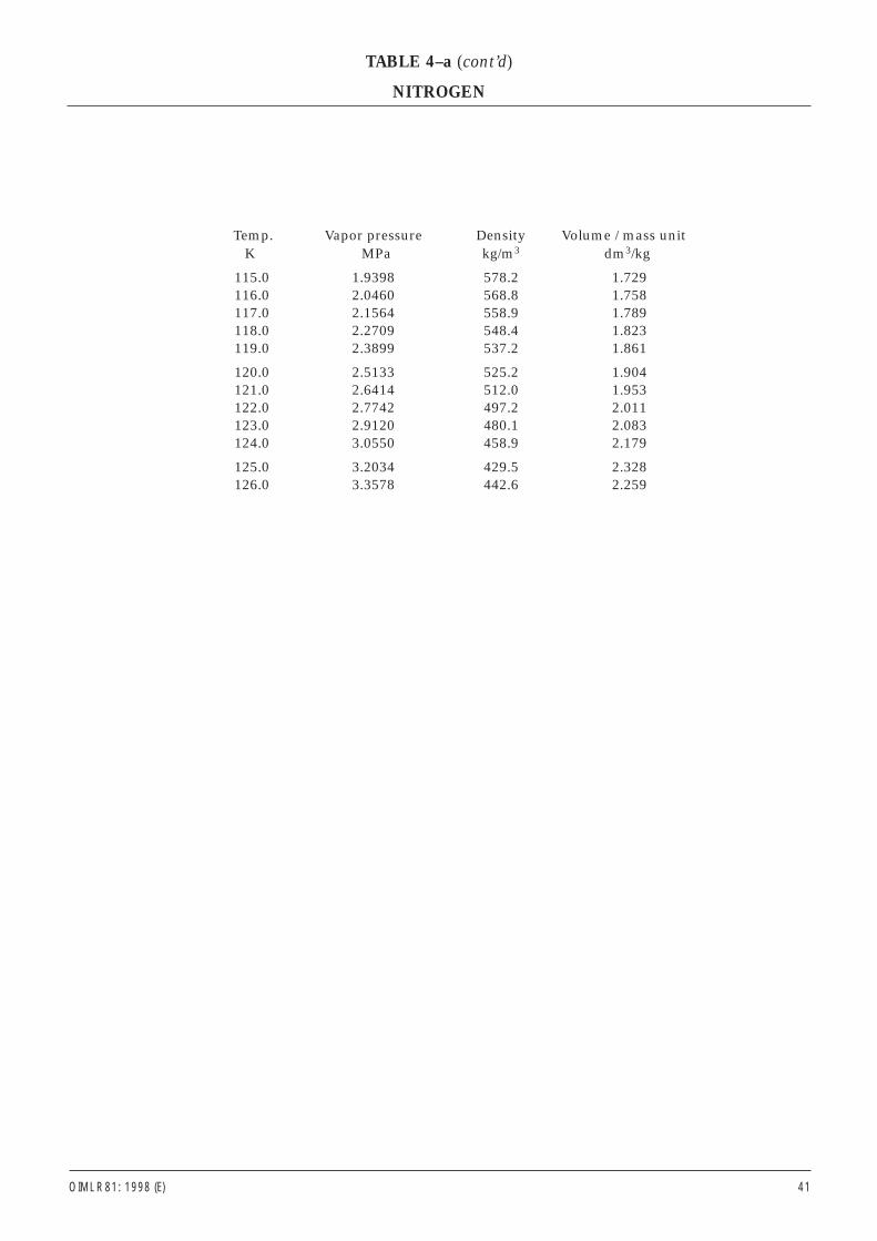
OIML R 81: 1998 (E) 41
Temp. Vapor pressure Density Volume / mass unitK MPa kg/m3 dm3/kg
115.0 1.9398 578.2 1.729116.0 2.0460 568.8 1.758117.0 2.1564 558.9 1.789118.0 2.2709 548.4 1.823119.0 2.3899 537.2 1.861
120.0 2.5133 525.2 1.904121.0 2.6414 512.0 1.953122.0 2.7742 497.2 2.011123.0 2.9120 480.1 2.083124.0 3.0550 458.9 2.179
125.0 3.2034 429.5 2.328126.0 3.3578 442.6 2.259
TABLE 4–a (cont’d)
NITROGEN
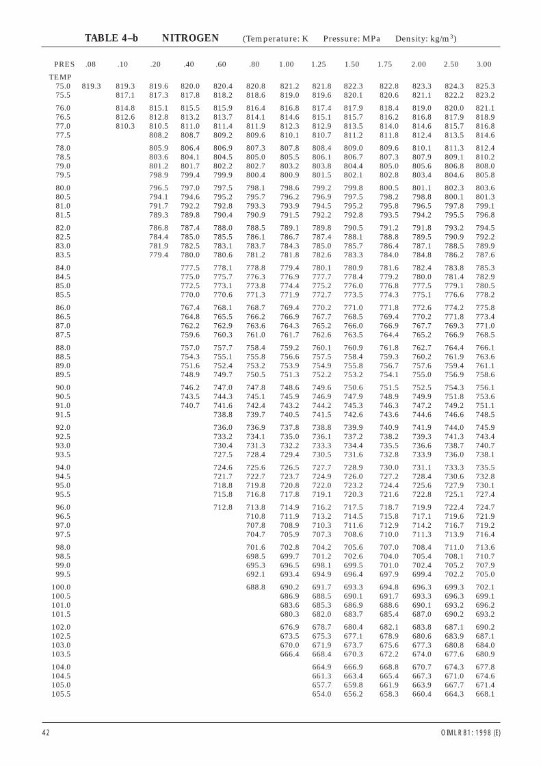
PRES .08 .10 .20 .40 .60 .80 1.00 1.25 1.50 1.75 2.00 2.50 3.00
TEMP75.0 819.3 819.3 819.6 820.0 820.4 820.8 821.2 821.8 822.3 822.8 823.3 824.3 825.375.5 817.1 817.3 817.8 818.2 818.6 819.0 819.6 820.1 820.6 821.1 822.2 823.2
76.0 814.8 815.1 815.5 815.9 816.4 816.8 817.4 817.9 818.4 819.0 820.0 821.176.5 812.6 812.8 813.2 813.7 814.1 814.6 815.1 815.7 816.2 816.8 817.9 818.977.0 810.3 810.5 811.0 811.4 811.9 812.3 812.9 813.5 814.0 814.6 815.7 816.877.5 808.2 808.7 809.2 809.6 810.1 810.7 811.2 811.8 812.4 813.5 814.6
78.0 805.9 806.4 806.9 807.3 807.8 808.4 809.0 809.6 810.1 811.3 812.478.5 803.6 804.1 804.5 805.0 805.5 806.1 806.7 807.3 807.9 809.1 810.279.0 801.2 801.7 802.2 802.7 803.2 803.8 804.4 805.0 805.6 806.8 808.079.5 798.9 799.4 799.9 800.4 800.9 801.5 802.1 802.8 803.4 804.6 805.8
80.0 796.5 797.0 797.5 798.1 798.6 799.2 799.8 800.5 801.1 802.3 803.680.5 794.1 794.6 795.2 795.7 796.2 796.9 797.5 798.2 798.8 800.1 801.381.0 791.7 792.2 792.8 793.3 793.9 794.5 795.2 795.8 796.5 797.8 799.181.5 789.3 789.8 790.4 790.9 791.5 792.2 792.8 793.5 794.2 795.5 796.8
82.0 786.8 787.4 788.0 788.5 789.1 789.8 790.5 791.2 791.8 793.2 794.582.5 784.4 785.0 785.5 786.1 786.7 787.4 788.1 788.8 789.5 790.9 792.283.0 781.9 782.5 783.1 783.7 784.3 785.0 785.7 786.4 787.1 788.5 789.983.5 779.4 780.0 780.6 781.2 781.8 782.6 783.3 784.0 784.8 786.2 787.6
84.0 777.5 778.1 778.8 779.4 780.1 780.9 781.6 782.4 783.8 785.384.5 775.0 775.7 776.3 776.9 777.7 778.4 779.2 780.0 781.4 782.985.0 772.5 773.1 773.8 774.4 775.2 776.0 776.8 777.5 779.1 780.585.5 770.0 770.6 771.3 771.9 772.7 773.5 774.3 775.1 776.6 778.2
86.0 767.4 768.1 768.7 769.4 770.2 771.0 771.8 772.6 774.2 775.886.5 764.8 765.5 766.2 766.9 767.7 768.5 769.4 770.2 771.8 773.487.0 762.2 762.9 763.6 764.3 765.2 766.0 766.9 767.7 769.3 771.087.5 759.6 760.3 761.0 761.7 762.6 763.5 764.4 765.2 766.9 768.5
88.0 757.0 757.7 758.4 759.2 760.1 760.9 761.8 762.7 764.4 766.188.5 754.3 755.1 755.8 756.6 757.5 758.4 759.3 760.2 761.9 763.689.0 751.6 752.4 753.2 753.9 754.9 755.8 756.7 757.6 759.4 761.189.5 748.9 749.7 750.5 751.3 752.2 753.2 754.1 755.0 756.9 758.6
90.0 746.2 747.0 747.8 748.6 749.6 750.6 751.5 752.5 754.3 756.190.5 743.5 744.3 745.1 745.9 746.9 747.9 748.9 749.9 751.8 753.691.0 740.7 741.6 742.4 743.2 744.2 745.3 746.3 747.2 749.2 751.191.5 738.8 739.7 740.5 741.5 742.6 743.6 744.6 746.6 748.5
92.0 736.0 736.9 737.8 738.8 739.9 740.9 741.9 744.0 745.992.5 733.2 734.1 735.0 736.1 737.2 738.2 739.3 741.3 743.493.0 730.4 731.3 732.2 733.3 734.4 735.5 736.6 738.7 740.793.5 727.5 728.4 729.4 730.5 731.6 732.8 733.9 736.0 738.1
94.0 724.6 725.6 726.5 727.7 728.9 730.0 731.1 733.3 735.594.5 721.7 722.7 723.7 724.9 726.0 727.2 728.4 730.6 732.895.0 718.8 719.8 720.8 722.0 723.2 724.4 725.6 727.9 730.195.5 715.8 716.8 717.8 719.1 720.3 721.6 722.8 725.1 727.4
96.0 712.8 713.8 714.9 716.2 717.5 718.7 719.9 722.4 724.796.5 710.8 711.9 713.2 714.5 715.8 717.1 719.6 721.997.0 707.8 708.9 710.3 711.6 712.9 714.2 716.7 719.297.5 704.7 705.9 707.3 708.6 710.0 711.3 713.9 716.4
98.0 701.6 702.8 704.2 705.6 707.0 708.4 711.0 713.698.5 698.5 699.7 701.2 702.6 704.0 705.4 708.1 710.799.0 695.3 696.5 698.1 699.5 701.0 702.4 705.2 707.999.5 692.1 693.4 694.9 696.4 697.9 699.4 702.2 705.0
100.0 688.8 690.2 691.7 693.3 694.8 696.3 699.3 702.1100.5 686.9 688.5 690.1 691.7 693.3 696.3 699.1101.0 683.6 685.3 686.9 688.6 690.1 693.2 696.2101.5 680.3 682.0 683.7 685.4 687.0 690.2 693.2
102.0 676.9 678.7 680.4 682.1 683.8 687.1 690.2102.5 673.5 675.3 677.1 678.9 680.6 683.9 687.1103.0 670.0 671.9 673.7 675.6 677.3 680.8 684.0103.5 666.4 668.4 670.3 672.2 674.0 677.6 680.9
104.0 664.9 666.9 668.8 670.7 674.3 677.8104.5 661.3 663.4 665.4 667.3 671.0 674.6105.0 657.7 659.8 661.9 663.9 667.7 671.4105.5 654.0 656.2 658.3 660.4 664.3 668.1
42 OIML R 81: 1998 (E)
TABLE 4–b NITROGEN (Temperature: K Pressure: MPa Density: kg/m3)
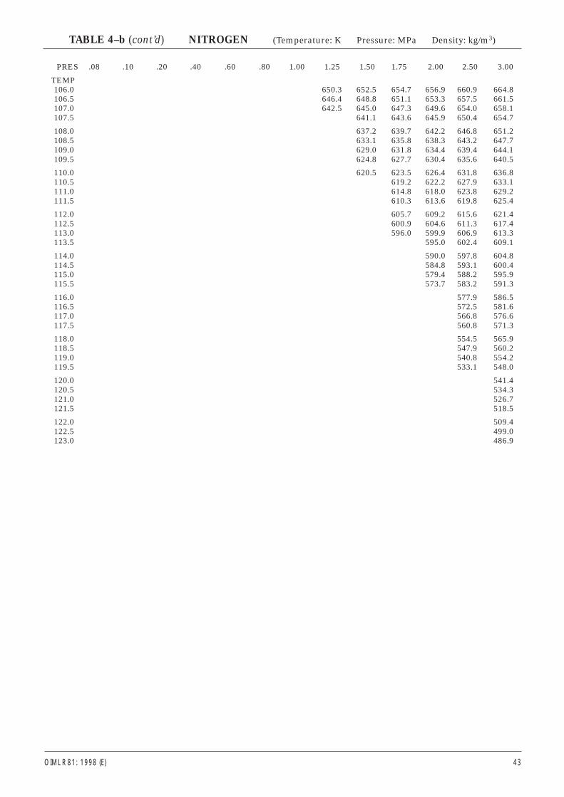
PRES .08 .10 .20 .40 .60 .80 1.00 1.25 1.50 1.75 2.00 2.50 3.00
TEMP106.0 650.3 652.5 654.7 656.9 660.9 664.8106.5 646.4 648.8 651.1 653.3 657.5 661.5107.0 642.5 645.0 647.3 649.6 654.0 658.1107.5 641.1 643.6 645.9 650.4 654.7
108.0 637.2 639.7 642.2 646.8 651.2108.5 633.1 635.8 638.3 643.2 647.7109.0 629.0 631.8 634.4 639.4 644.1109.5 624.8 627.7 630.4 635.6 640.5
110.0 620.5 623.5 626.4 631.8 636.8110.5 619.2 622.2 627.9 633.1111.0 614.8 618.0 623.8 629.2111.5 610.3 613.6 619.8 625.4
112.0 605.7 609.2 615.6 621.4112.5 600.9 604.6 611.3 617.4113.0 596.0 599.9 606.9 613.3113.5 595.0 602.4 609.1
114.0 590.0 597.8 604.8114.5 584.8 593.1 600.4115.0 579.4 588.2 595.9115.5 573.7 583.2 591.3
116.0 577.9 586.5116.5 572.5 581.6117.0 566.8 576.6117.5 560.8 571.3
118.0 554.5 565.9118.5 547.9 560.2119.0 540.8 554.2119.5 533.1 548.0
120.0 541.4120.5 534.3121.0 526.7121.5 518.5
122.0 509.4122.5 499.0123.0 486.9
OIML R 81: 1998 (E) 43
TABLE 4–b (cont’d) NITROGEN (Temperature: K Pressure: MPa Density: kg/m3)
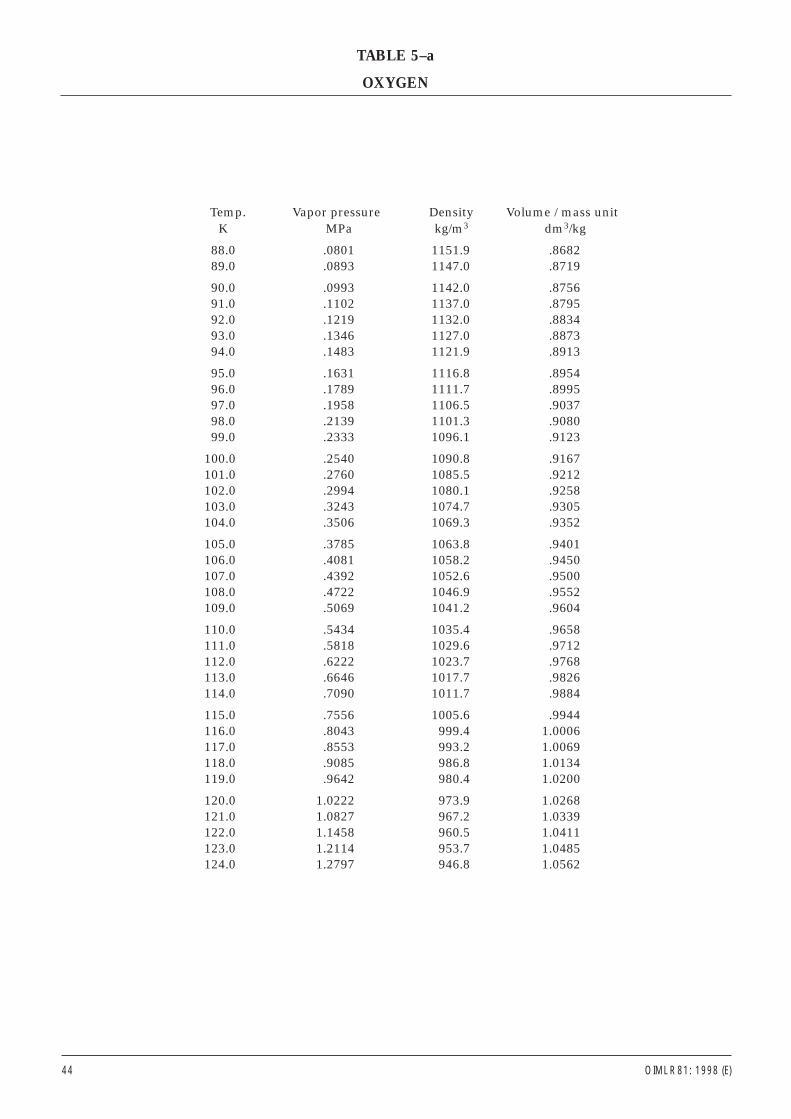
Temp. Vapor pressure Density Volume / mass unitK MPa kg/m3 dm3/kg
88.0 .0801 1151.9 .868289.0 .0893 1147.0 .8719
90.0 .0993 1142.0 .875691.0 .1102 1137.0 .879592.0 .1219 1132.0 .883493.0 .1346 1127.0 .887394.0 .1483 1121.9 .8913
95.0 .1631 1116.8 .895496.0 .1789 1111.7 .899597.0 .1958 1106.5 .903798.0 .2139 1101.3 .908099.0 .2333 1096.1 .9123
100.0 .2540 1090.8 .9167101.0 .2760 1085.5 .9212102.0 .2994 1080.1 .9258103.0 .3243 1074.7 .9305104.0 .3506 1069.3 .9352
105.0 .3785 1063.8 .9401106.0 .4081 1058.2 .9450107.0 .4392 1052.6 .9500108.0 .4722 1046.9 .9552109.0 .5069 1041.2 .9604
110.0 .5434 1035.4 .9658111.0 .5818 1029.6 .9712112.0 .6222 1023.7 .9768113.0 .6646 1017.7 .9826114.0 .7090 1011.7 .9884
115.0 .7556 1005.6 .9944116.0 .8043 999.4 1.0006117.0 .8553 993.2 1.0069118.0 .9085 986.8 1.0134119.0 .9642 980.4 1.0200
120.0 1.0222 973.9 1.0268121.0 1.0827 967.2 1.0339122.0 1.1458 960.5 1.0411123.0 1.2114 953.7 1.0485124.0 1.2797 946.8 1.0562
44 OIML R 81: 1998 (E)
TABLE 5–a
OXYGEN
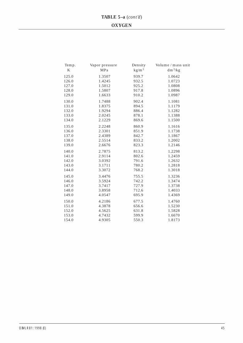
Temp. Vapor pressure Density Volume / mass unitK MPa kg/m3 dm3/kg
125.0 1.3507 939.7 1.0642126.0 1.4245 932.5 1.0723127.0 1.5012 925.2 1.0808128.0 1.5807 917.8 1.0896129.0 1.6633 910.2 1.0987
130.0 1.7488 902.4 1.1081131.0 1.8375 894.5 1.1179132.0 1.9294 886.4 1.1282133.0 2.0245 878.1 1.1388134.0 2.1229 869.6 1.1500
135.0 2.2248 860.9 1.1616136.0 2.3301 851.9 1.1738137.0 2.4389 842.7 1.1867138.0 2.5514 833.2 1.2002139.0 2.6676 823.3 1.2146
140.0 2.7875 813.2 1.2298141.0 2.9114 802.6 1.2459142.0 3.0392 791.6 1.2632143.0 3.1711 780.2 1.2818144.0 3.3072 768.2 1.3018
145.0 3.4476 755.5 1.3236146.0 3.5924 742.2 1.3474147.0 3.7417 727.9 1.3738148.0 3.8958 712.6 1.4033149.0 4.0547 695.9 1.4369
150.0 4.2186 677.5 1.4760151.0 4.3878 656.6 1.5230152.0 4.5625 631.8 1.5828153.0 4.7432 599.9 1.6670154.0 4.9305 550.3 1.8173
OIML R 81: 1998 (E) 45
TABLE 5–a (cont’d)
OXYGEN
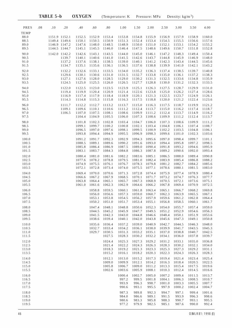
PRES .08 .10 .20 .40 .60 .80 1.00 1.50 2.00 2.50 3.00 3.50 4.00
TEMP88.0 1151.9 1152.1 1152.5 1152.9 1153.4 1153.8 1154.8 1155.9 1156.9 1157.9 1158.9 1160.088.5 1149.4 1149.6 1150.1 1150.5 1150.9 1151.3 1152.4 1153.4 1154.5 1155.5 1156.6 1157.689.0 1146.9 1147.2 1147.6 1148.0 1148.5 1148.9 1150.0 1151.0 1152.1 1153.1 1154.2 1155.289.5 1144.5 1144.7 1145.1 1145.5 1146.0 1146.4 1147.5 1148.6 1149.6 1150.7 1151.8 1152.8
90.0 1142.0 1142.2 1142.6 1143.1 1143.5 1144.0 1145.0 1146.1 1147.2 1148.3 1149.4 1150.490.5 1139.7 1140.1 1140.6 1141.0 1141.5 1142.6 1143.7 1144.8 1145.9 1146.9 1148.091.0 1137.2 1137.6 1138.1 1138.5 1139.0 1140.1 1141.2 1142.3 1143.4 1144.5 1145.691.5 1134.7 1135.1 1135.6 1136.1 1136.5 1137.6 1138.8 1139.9 1141.0 1142.1 1143.2
92.0 1132.2 1132.6 1133.1 1133.5 1134.0 1135.2 1136.3 1137.4 1138.5 1139.7 1140.892.5 1129.6 1130.1 1130.6 1131.0 1131.5 1132.7 1133.8 1135.0 1136.1 1137.2 1138.393.0 1127.1 1127.6 1128.0 1128.5 1129.0 1130.2 1131.3 1132.5 1133.6 1134.8 1135.993.5 1124.5 1125.0 1125.5 1126.0 1126.5 1127.7 1128.8 1130.0 1131.2 1132.3 1133.5
94.0 1122.0 1122.5 1123.0 1123.5 1123.9 1125.1 1126.3 1127.5 1128.7 1129.9 1131.094.5 1119.4 1119.9 1120.4 1120.9 1121.4 1122.6 1123.8 1125.0 1126.2 1127.4 1128.695.0 1116.9 1117.4 1117.9 1118.4 1118.9 1120.1 1121.3 1122.5 1123.7 1124.9 1126.195.5 1114.3 1114.8 1115.3 1115.8 1116.3 1117.5 1118.8 1120.0 1121.2 1122.4 1123.6
96.0 1111.7 1112.2 1112.7 1113.2 1113.7 1115.0 1116.3 1117.5 1118.7 1119.9 1121.296.5 1109.1 1109.6 1110.1 1110.6 1111.2 1112.4 1113.7 1115.0 1116.2 1117.4 1118.797.0 1106.5 1107.0 1107.5 1108.1 1108.6 1109.9 1111.2 1112.4 1113.7 1114.9 1116.297.5 1104.4 1104.9 1105.5 1106.0 1107.3 1108.6 1109.9 1111.2 1112.4 1113.7
98.0 1101.8 1102.3 1102.8 1103.4 1104.7 1106.0 1107.3 1108.6 1109.9 1111.298.5 1099.1 1099.7 1100.2 1100.8 1102.1 1103.4 1104.8 1106.1 1107.4 1108.799.0 1096.5 1097.0 1097.6 1098.1 1099.5 1100.9 1102.2 1103.5 1104.8 1106.199.5 1093.8 1094.4 1094.9 1095.5 1096.9 1098.3 1099.6 1101.0 1102.3 1103.6
100.0 1091.2 1091.7 1092.3 1092.9 1094.3 1095.6 1097.0 1098.4 1099.7 1101.1100.5 1088.5 1089.1 1089.6 1090.2 1091.6 1093.0 1094.4 1095.8 1097.2 1098.5101.0 1085.8 1086.4 1086.9 1087.5 1089.0 1090.4 1091.8 1093.2 1094.6 1095.9101.5 1083.1 1083.7 1084.3 1084.8 1086.3 1087.8 1089.2 1090.6 1092.0 1093.4
102.0 1080.4 1081.0 1081.6 1082.2 1083.6 1085.1 1086.5 1088.0 1089.4 1090.8102.5 1077.6 1078.2 1078.8 1079.5 1081.0 1082.4 1083.9 1085.4 1086.8 1088.2103.0 1074.9 1075.5 1076.1 1076.7 1078.3 1079.8 1081.2 1082.7 1084.2 1085.6103.5 1072.1 1072.8 1073.4 1074.0 1075.5 1077.1 1078.6 1080.1 1081.5 1083.0
104.0 1069.4 1070.0 1070.6 1071.3 1072.8 1074.4 1075.9 1077.4 1078.9 1080.4104.5 1066.6 1067.2 1067.9 1068.5 1070.1 1071.7 1073.2 1074.7 1076.3 1077.7105.0 1063.8 1064.4 1065.1 1065.7 1067.3 1068.9 1070.5 1072.1 1073.6 1075.1105.5 1061.0 1061.6 1062.3 1062.9 1064.6 1066.2 1067.8 1069.4 1070.9 1072.5
106.0 1058.8 1059.5 1060.1 1061.8 1063.4 1065.1 1066.7 1068.2 1069.8106.5 1056.0 1056.6 1057.3 1059.0 1060.7 1062.3 1063.9 1065.5 1067.1107.0 1053.1 1053.8 1054.5 1056.2 1057.9 1059.6 1061.2 1062.8 1064.4107.5 1050.2 1051.0 1051.7 1053.4 1055.1 1056.8 1058.5 1060.1 1061.7
108.0 1047.4 1048.1 1048.8 1050.6 1052.3 1054.0 1055.7 1057.4 1059.0108.5 1044.5 1045.2 1045.9 1047.7 1049.5 1051.2 1052.9 1054.6 1056.3109.0 1041.5 1042.3 1043.0 1044.8 1046.6 1048.4 1050.1 1051.9 1053.6109.5 1038.6 1039.4 1040.1 1042.0 1043.8 1045.6 1047.3 1049.1 1050.8
110.0 1035.6 1036.4 1037.2 1039.0 1040.9 1042.7 1044.5 1046.3 1048.0110.5 1032.7 1033.4 1034.2 1036.1 1038.0 1039.9 1041.7 1043.5 1045.3111.0 1029.7 1030.5 1031.3 1033.2 1035.1 1037.0 1038.8 1040.7 1042.5111.5 1027.5 1028.3 1030.2 1032.2 1034.1 1036.0 1037.8 1039.7
112.0 1024.4 1025.3 1027.3 1029.2 1031.2 1033.1 1035.0 1036.8112.5 1021.4 1022.2 1024.3 1026.3 1028.3 1030.2 1032.1 1034.0113.0 1018.3 1019.2 1021.3 1023.3 1025.3 1027.3 1029.2 1031.1113.5 1015.2 1016.1 1018.2 1020.3 1022.3 1024.3 1026.3 1028.3
114.0 1012.1 1013.0 1015.2 1017.3 1019.4 1021.4 1023.4 1025.4114.5 1009.0 1009.9 1012.1 1014.2 1016.3 1018.4 1020.5 1022.5115.0 1005.8 1006.7 1009.0 1011.2 1013.3 1015.4 1017.5 1019.6115.5 1002.6 1003.6 1005.9 1008.1 1010.3 1012.4 1014.5 1016.6
116.0 1000.4 1002.7 1005.0 1007.2 1009.4 1011.5 1013.7116.5 997.2 999.5 1001.8 1004.1 1006.3 1008.5 1010.7117.0 993.9 996.3 998.7 1001.0 1003.3 1005.5 1007.7117.5 990.6 993.1 995.5 997.9 1000.2 1002.4 1004.7
118.0 987.3 989.8 992.3 994.7 997.1 999.4 1001.6118.5 984.0 986.6 989.1 991.5 993.9 996.3 998.6119.0 980.6 983.3 985.8 988.3 990.7 993.1 995.5119.5 977.2 979.9 982.5 985.1 987.6 990.0 992.4
46 OIML R 81: 1998 (E)
TABLE 5–b OXYGEN (Temperature: K Pressure: MPa Density: kg/m3)
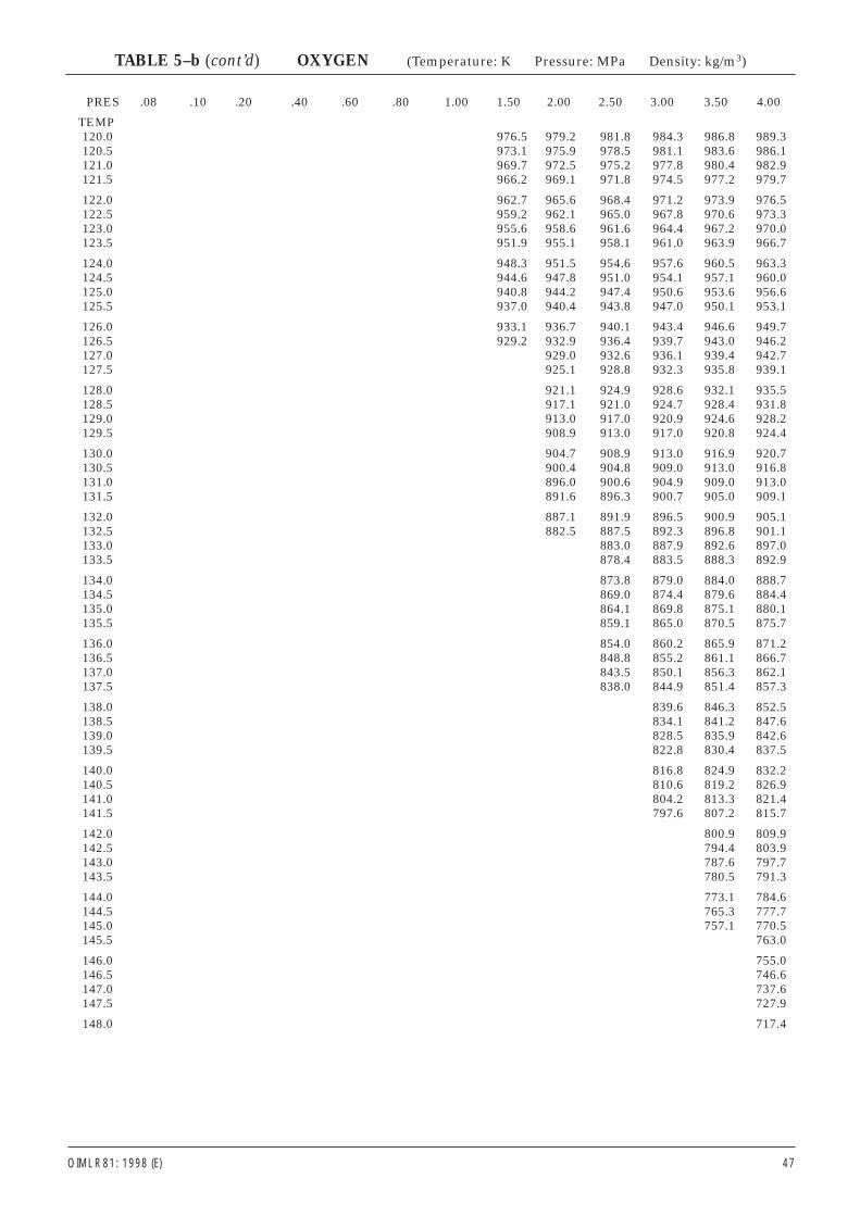
OIML R 81: 1998 (E) 47
PRES .08 .10 .20 .40 .60 .80 1.00 1.50 2.00 2.50 3.00 3.50 4.00
TEMP120.0 976.5 979.2 981.8 984.3 986.8 989.3120.5 973.1 975.9 978.5 981.1 983.6 986.1121.0 969.7 972.5 975.2 977.8 980.4 982.9121.5 966.2 969.1 971.8 974.5 977.2 979.7
122.0 962.7 965.6 968.4 971.2 973.9 976.5122.5 959.2 962.1 965.0 967.8 970.6 973.3123.0 955.6 958.6 961.6 964.4 967.2 970.0123.5 951.9 955.1 958.1 961.0 963.9 966.7
124.0 948.3 951.5 954.6 957.6 960.5 963.3124.5 944.6 947.8 951.0 954.1 957.1 960.0125.0 940.8 944.2 947.4 950.6 953.6 956.6125.5 937.0 940.4 943.8 947.0 950.1 953.1
126.0 933.1 936.7 940.1 943.4 946.6 949.7126.5 929.2 932.9 936.4 939.7 943.0 946.2127.0 929.0 932.6 936.1 939.4 942.7127.5 925.1 928.8 932.3 935.8 939.1
128.0 921.1 924.9 928.6 932.1 935.5128.5 917.1 921.0 924.7 928.4 931.8129.0 913.0 917.0 920.9 924.6 928.2129.5 908.9 913.0 917.0 920.8 924.4
130.0 904.7 908.9 913.0 916.9 920.7130.5 900.4 904.8 909.0 913.0 916.8131.0 896.0 900.6 904.9 909.0 913.0131.5 891.6 896.3 900.7 905.0 909.1
132.0 887.1 891.9 896.5 900.9 905.1132.5 882.5 887.5 892.3 896.8 901.1133.0 883.0 887.9 892.6 897.0133.5 878.4 883.5 888.3 892.9
134.0 873.8 879.0 884.0 888.7134.5 869.0 874.4 879.6 884.4135.0 864.1 869.8 875.1 880.1135.5 859.1 865.0 870.5 875.7
136.0 854.0 860.2 865.9 871.2136.5 848.8 855.2 861.1 866.7137.0 843.5 850.1 856.3 862.1137.5 838.0 844.9 851.4 857.3
138.0 839.6 846.3 852.5138.5 834.1 841.2 847.6139.0 828.5 835.9 842.6139.5 822.8 830.4 837.5
140.0 816.8 824.9 832.2140.5 810.6 819.2 826.9141.0 804.2 813.3 821.4141.5 797.6 807.2 815.7
142.0 800.9 809.9142.5 794.4 803.9143.0 787.6 797.7143.5 780.5 791.3
144.0 773.1 784.6144.5 765.3 777.7145.0 757.1 770.5145.5 763.0
146.0 755.0146.5 746.6147.0 737.6147.5 727.9
148.0 717.4
TABLE 5–b (cont’d) OXYGEN (Temperature: K Pressure: MPa Density: kg/m3)
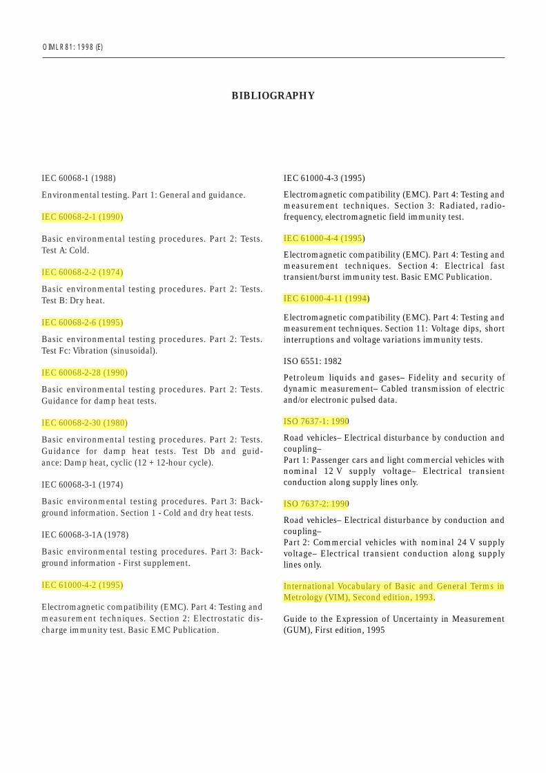
IEC 60068-1 (1988)
Environmental testing. Part 1: General and guidance.
IEC 60068-2-1 (1990)
Basic environmental testing procedures. Part 2: Tests.Test A: Cold.
IEC 60068-2-2 (1974)
Basic environmental testing procedures. Part 2: Tests.Test B: Dry heat.
IEC 60068-2-6 (1995)
Basic environmental testing procedures. Part 2: Tests.Test Fc: Vibration (sinusoidal).
IEC 60068-2-28 (1990)
Basic environmental testing procedures. Part 2: Tests.Guidance for damp heat tests.
IEC 60068-2-30 (1980)
Basic environmental testing procedures. Part 2: Tests.Guidance for damp heat tests. Test Db and guid-ance: Damp heat, cyclic (12 + 12-hour cycle).
IEC 60068-3-1 (1974)
Basic environmental testing procedures. Part 3: Back-ground information. Section 1 - Cold and dry heat tests.
IEC 60068-3-1A (1978)
Basic environmental testing procedures. Part 3: Back-ground information - First supplement.
IEC 61000-4-2 (1995)
Electromagnetic compatibility (EMC). Part 4: Testing andmeasurement techniques. Section 2: Electrostatic dis-charge immunity test. Basic EMC Publication.
IEC 61000-4-3 (1995)
Electromagnetic compatibility (EMC). Part 4: Testing andmeasurement techniques. Section 3: Radiated, radio-frequency, electromagnetic field immunity test.
IEC 61000-4-4 (1995)
Electromagnetic compatibility (EMC). Part 4: Testing andmeasurement techniques. Section 4: Electrical fasttransient/burst immunity test. Basic EMC Publication.
IEC 61000-4-11 (1994)
Electromagnetic compatibility (EMC). Part 4: Testing andmeasurement techniques. Section 11: Voltage dips, shortinterruptions and voltage variations immunity tests.
ISO 6551: 1982
Petroleum liquids and gases– Fidelity and security ofdynamic measurement– Cabled transmission of electricand/or electronic pulsed data.
ISO 7637-1: 1990
Road vehicles– Electrical disturbance by conduction andcoupling– Part 1: Passenger cars and light commercial vehicles withnominal 12 V supply voltage– Electrical transientconduction along supply lines only.
ISO 7637-2: 1990
Road vehicles– Electrical disturbance by conduction andcoupling– Part 2: Commercial vehicles with nominal 24 V supplyvoltage– Electrical transient conduction along supplylines only.
International Vocabulary of Basic and General Terms inMetrology (VIM), Second edition, 1993.
Guide to the Expression of Uncertainty in Measurement(GUM), First edition, 1995
BIBLIOGRAPHY
OIML R 81: 1998 (E)
Dynamic measuring devices and systems for cryogenic liquids
Annex D: Test Report Format
Dispositifs et systèmes de mesure dynamique des liquides cryogéniques
Annexe D: Format du rapport d’essai
OIM
LR81
Ann
ex D
Edi
tion
2006
(E)
OIML R 81Annex D
Edition 2006 (E)
ORGANISATION INTERNATIONALE
DE MÉTROLOGIE LÉGALE
INTERNATIONAL ORGANIZATION
OF LEGAL METROLOGY
INTERNATIONAL
RECOMMENDATION
OIML R 81 Annex D: 2006 (E)
2
Contents
Foreword .....................................................................................................................................................3
Introduction ...................................................................................................................................................4
D.1 General information concerning the pattern (type) .....................................................................7
D.2 General information concerning the test conditions....................................................................8
D.3 Metrological requirements: Checklist .........................................................................................9
D.4 Technical requirements: Checklist ............................................................................................10
D.5 Requirements for electronic measuring systems: Checklist......................................................17
D.6 Summary of the tests .................................................................................................................23
D.7 Tests for maximum errors .........................................................................................................24
D.7.1 Tests for maximum errors - Flowrate, accuracy and repeatability ............................................24
D.7.2 Tests for maximum errors - Minimum measured quantity........................................................25
D.7.3 Tests for maximum errors - Flow disturbances.........................................................................26
D.8 Dry heat test ..............................................................................................................................27
D.9 Cold test ....................................................................................................................................28
D.10 Damp heat. Performance test after cycle 2................................................................................29
D.11 Vibration test .............................................................................................................................30
D.12 Power voltage variation test ......................................................................................................31
D.12.1 AC power voltage variation test................................................................................................31
D.12.2 DC power voltage variation test................................................................................................33
D.13 Short time power reduction test ................................................................................................35
D.14 Electrical bursts test ..................................................................................................................37
D.14.1 Electrical bursts test for power supply lines..............................................................................37
D.14.2 Electrical bursts test for I/O circuits and communication devices ............................................41
D.15 Electrostatic discharge test ........................................................................................................45
D.15.1 Electrostatic discharge test - Direct application ........................................................................45
D.15.2 Electrostatic discharge test - Indirect application......................................................................49
D.15.3 Electrostatic discharge test - Test setup ....................................................................................53
D.16 Electromagnetic susceptibility test............................................................................................54
D.17 Perturbations on DC voltage powered instruments ...................................................................59
D.18 Endurance test ...........................................................................................................................62
D.18.1 Performance test before endurance test.....................................................................................62
D.18.2 Performance test after endurance test........................................................................................63
OIML R 81 Annex D: 2006 (E)
3
Foreword
The International Organization of Legal Metrology (OIML) is a worldwide, intergovernmental organization whose primary aim is to harmonize the regulations and metrological controls applied by the national metrological services, or related organizations, of its Member States. The main categories of OIML publications are:
International Recommendations (OIML R), which are model regulations that establish the metrological characteristics required of certain measuring instruments and which specify methods and equipment for checking their conformity. OIML Member States shall implement these Recommendations to the greatest possible extent;
International Documents (OIML D), which are informative in nature and which are intended to harmonize and improve work in the field of legal metrology;
International Guides (OIML G), which are also informative in nature and which are intended to give guidelines for the application of certain requirements to legal metrology; and
International Basic Publications (OIML B), which define the operating rules of the various OIML structures and systems.
OIML Draft Recommendations, Documents and Guides are developed by Technical Committees or Subcommittees which comprise representatives from the Member States. Certain international and regional institutions also participate on a consultation basis. Cooperative agreements have been established between the OIML and certain institutions, such as ISO and the IEC, with the objective of avoiding contradictory requirements. Consequently, manufacturers and users of measuring instruments, test laboratories, etc. may simultaneously apply OIML publications and those of other institutions.
International Recommendations, Documents, Guides and Basic Publications are published in English (E) and translated into French (F) and are subject to periodic revision.
Additionally, the OIML publishes or participates in the publication of Vocabularies (OIML V) and periodically commissions legal metrology experts to write Expert Reports (OIML E). Expert Reports are intended to provide information and advice, and are written solely from the viewpoint of their author, without the involvement of a Technical Committee or Subcommittee, nor that of the CIML. Thus, they do not necessarily represent the views of the OIML.
This publication - reference OIML R 81 Annex D, Edition 2006 (E) - was developed by the OIML Technical Subcommittee TC 8/SC 6 Measurement of cryogenic liquids. It was approved for final publication by the International Committee of Legal Metrology in 1999.
OIML Publications may be downloaded from the OIML web site in the form of PDF files. Additional information on OIML Publications may be obtained from the Organization’s headquarters:
Bureau International de Métrologie Légale 11, rue Turgot - 75009 Paris - France Telephone: 33 (0)1 48 78 12 82 Fax: 33 (0)1 42 82 17 27 E-mail: [email protected] Internet: www.oiml.org
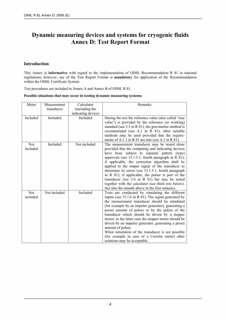
OIML R 81 Annex D: 2006 (E)
4
Dynamic measuring devices and systems for cryogenic fluids Annex D: Test Report Format
Introduction This Annex is informative with regard to the implementation of OIML Recommendation R 81 in national regulations; however, use of the Test Report Format is mandatory for application of the Recommendation within the OIML Certificate System.
Test procedures are included in Annex A and Annex B of OIML R 81.
Possible situations that may occur in testing dynamic measuring systems:
Meter Measurement transducer
Calculator (including the
indicating device)
Remarks
Included Included Included During the test the reference value (also called “true value”) is provided by the reference (or working) standard (see 3.3 in R 81); the gravimetric method is recommended (see A.1 in R 81); other suitable methods may be used provided that the require-ments of A.1.1 in R 81 are met (see A.1 in R 81).
Not included
Included Not included The measurement transducer may be tested alone provided that the computing and indicating devices have been subject to separate pattern (type) approvals (see 15.1.5.1, fourth paragraph in R 81); if applicable, the correction algorithm shall be applied to the output signal of the transducer to determine its errors (see 15.1.5.1, fourth paragraph in R 81); if applicable, the pulser is part of the transducer (see 3.6 in R 81) but may be tested together with the calculator (see third row below). See also the remark above in the first sentence.
Not included
Not included Included Tests are conducted by simulating the different inputs (see 15.1.6 in R 81). The signal generated by the measurement transducer should be simulated (for example by an impulse generator), generating a preset amount of pulses or by the pulser of the transducer which should be driven by a stepper motor; in the latter case the stepper motor should be driven by an impulse generator, generating a preset amount of pulses. When simulation of the transducer is not possible (for example in case of a Coriolis meter) other solutions may be acceptable.
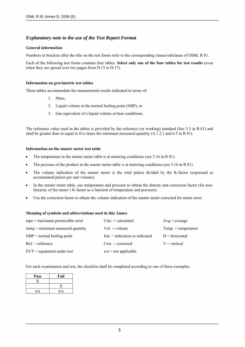
OIML R 81 Annex D: 2006 (E)
5
Explanatory note to the use of the Test Report Format General information
Numbers in brackets after the title on the test forms refer to the corresponding clause/subclause of OIML R 81.
Each of the following test forms contains four tables. Select only one of the four tables for test results (even when they are spread over two pages from D.13 to D.17).
Information on gravimetric test tables
Three tables accommodate the measurement results indicated in terms of:
1. Mass,
2. Liquid volume at the normal boiling point (NBP), or
3. Gas equivalent of a liquid volume at base conditions.
The reference value used in the tables is provided by the reference (or working) standard (See 3.3 in R 81) and shall be greater than or equal to five times the minimum measured quantity (A.1.2.1 and 6.5 in R 81).
Information on the master meter test table
• The temperature in the master meter table is at metering conditions (see 3.16 in R 81).
• The pressure of the product in the master meter table is at metering conditions (see 3.16 in R 81).
• The volume indication of the master meter is the total pulses divided by the K-factor (expressed as accumulated pulses per unit volume).
• In the master meter table, use temperature and pressure to obtain the density and correction factor (for non-linearity of the meter’s K-factor as a function of temperature and pressure).
• Use the correction factor to obtain the volume indication of the master meter corrected for meter error.
Meaning of symbols and abbreviations used in this Annex
mpe = maximum permissible error Calc. = calculated Avg.= average
mmq = minimum measured quantity Vol. = volume Temp. = temperature
NBP = normal boiling point Ind. = indication or indicated H = horizontal
Ref. = reference Corr. = corrected V = vertical
EUT = equipment under test n/a = not applicable
For each examination and test, the checklist shall be completed according to one of these examples:
Pass Fail X X
n/a n/a

OIML R 81 Annex D: 2006 (E)
6
Page numbering
A space has been left on the top of each page (starting on page 7) for numbering the pages of reports established following this model. In particular, each test is reported individually on a separate page following the relevant format.
For a given report, it is advisable to complete the sequential numbering of each page by indicating the total number of pages in the report.
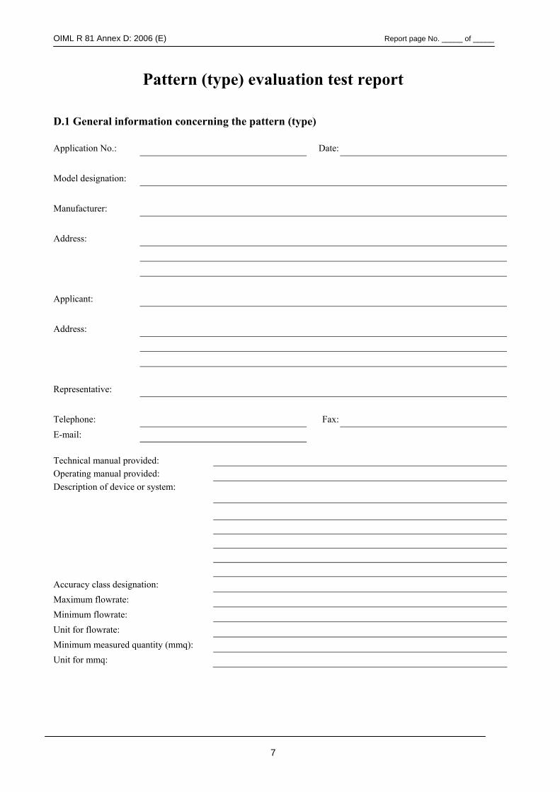
OIML R 81 Annex D: 2006 (E) Report page No. _____ of _____
7
Pattern (type) evaluation test report D.1 General information concerning the pattern (type) Application No.: Date: Model designation: Manufacturer: Address: Applicant: Address: Representative: Telephone: Fax: E-mail:
Technical manual provided:
Operating manual provided:
Description of device or system:
Accuracy class designation: Maximum flowrate: Minimum flowrate: Unit for flowrate: Minimum measured quantity (mmq): Unit for mmq:
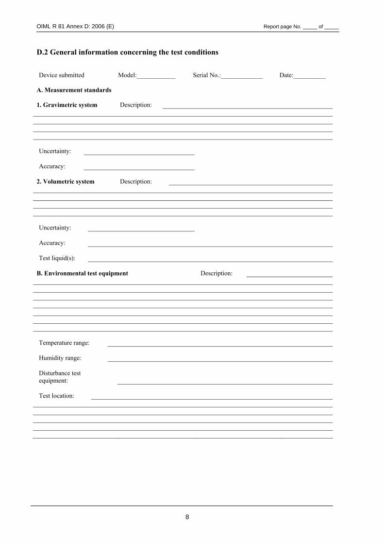
OIML R 81 Annex D: 2006 (E) Report page No. _____ of _____
8
D.2 General information concerning the test conditions Device submitted
Model:____________
Serial No.:_____________
Date:__________
A. Measurement standards
1. Gravimetric system
Description:
Uncertainty:
Accuracy:
2. Volumetric system
Description:
Uncertainty:
Accuracy:
Test liquid(s):
B. Environmental test equipment
Description:
Temperature range:
Humidity range:
Disturbance test equipment:
Test location:
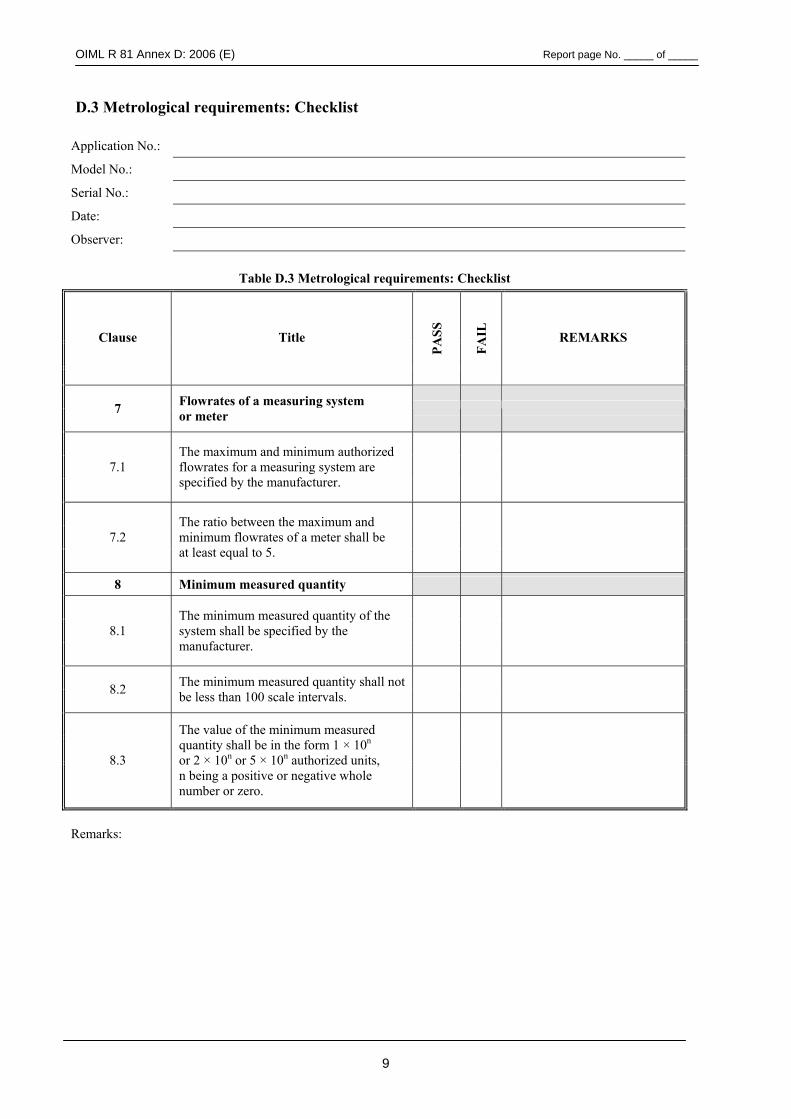
OIML R 81 Annex D: 2006 (E) Report page No. _____ of _____
9
D.3 Metrological requirements: Checklist
Application No.:
Model No.:
Serial No.:
Date:
Observer:
Table D.3 Metrological requirements: Checklist
Clause Title
PASS
FAIL
REMARKS
7 Flowrates of a measuring system or meter
7.1 The maximum and minimum authorized flowrates for a measuring system are specified by the manufacturer.
7.2 The ratio between the maximum and minimum flowrates of a meter shall be at least equal to 5.
8 Minimum measured quantity
8.1 The minimum measured quantity of the system shall be specified by the manufacturer.
8.2 The minimum measured quantity shall not be less than 100 scale intervals.
8.3
The value of the minimum measured quantity shall be in the form 1 × 10n or 2 × 10n or 5 × 10n authorized units, n being a positive or negative whole number or zero.
Remarks:
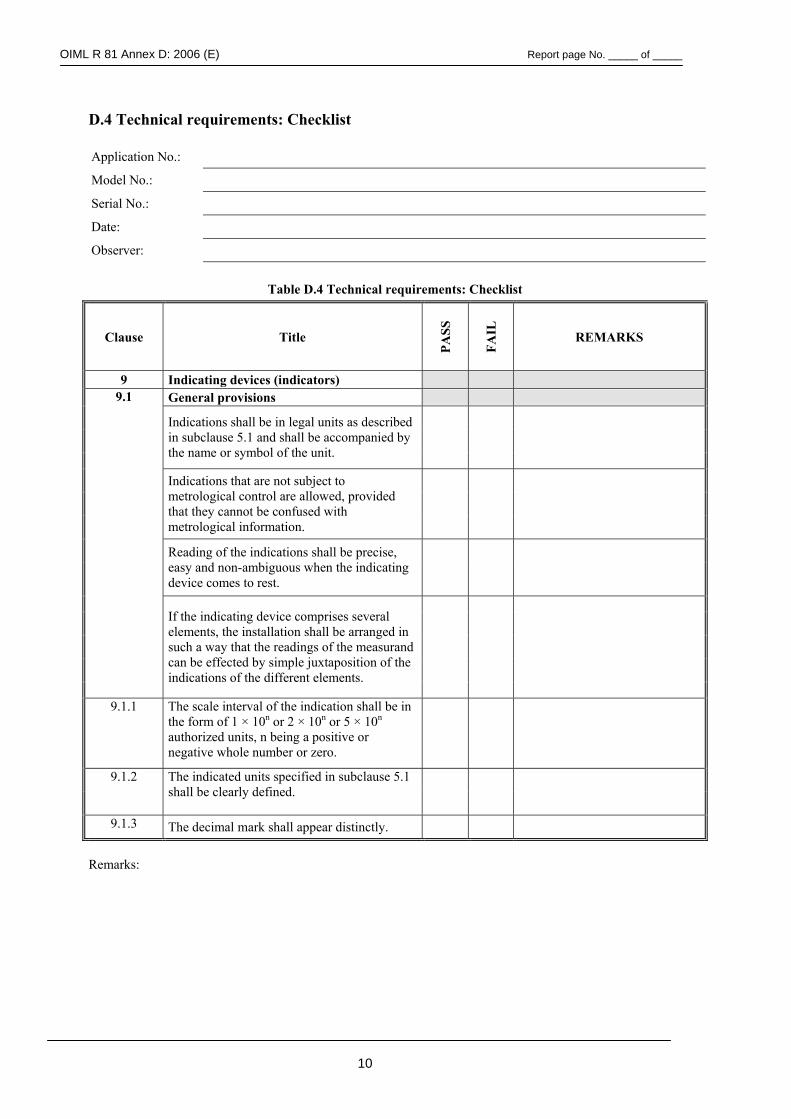
OIML R 81 Annex D: 2006 (E) Report page No. _____ of _____
10
D.4 Technical requirements: Checklist Application No.:
Model No.:
Serial No.:
Date:
Observer:
Table D.4 Technical requirements: Checklist
Clause Title
PASS
FAIL
REMARKS
9 Indicating devices (indicators) General provisions
Indications shall be in legal units as described in subclause 5.1 and shall be accompanied by the name or symbol of the unit.
Indications that are not subject to metrological control are allowed, provided that they cannot be confused with metrological information.
Reading of the indications shall be precise, easy and non-ambiguous when the indicating device comes to rest.
9.1
If the indicating device comprises several elements, the installation shall be arranged in such a way that the readings of the measurand can be effected by simple juxtaposition of the indications of the different elements.
9.1.1 The scale interval of the indication shall be in the form of 1 × 10n or 2 × 10n or 5 × 10n
authorized units, n being a positive or negative whole number or zero.
9.1.2 The indicated units specified in subclause 5.1 shall be clearly defined.
9.1.3 The decimal mark shall appear distinctly.
Remarks:
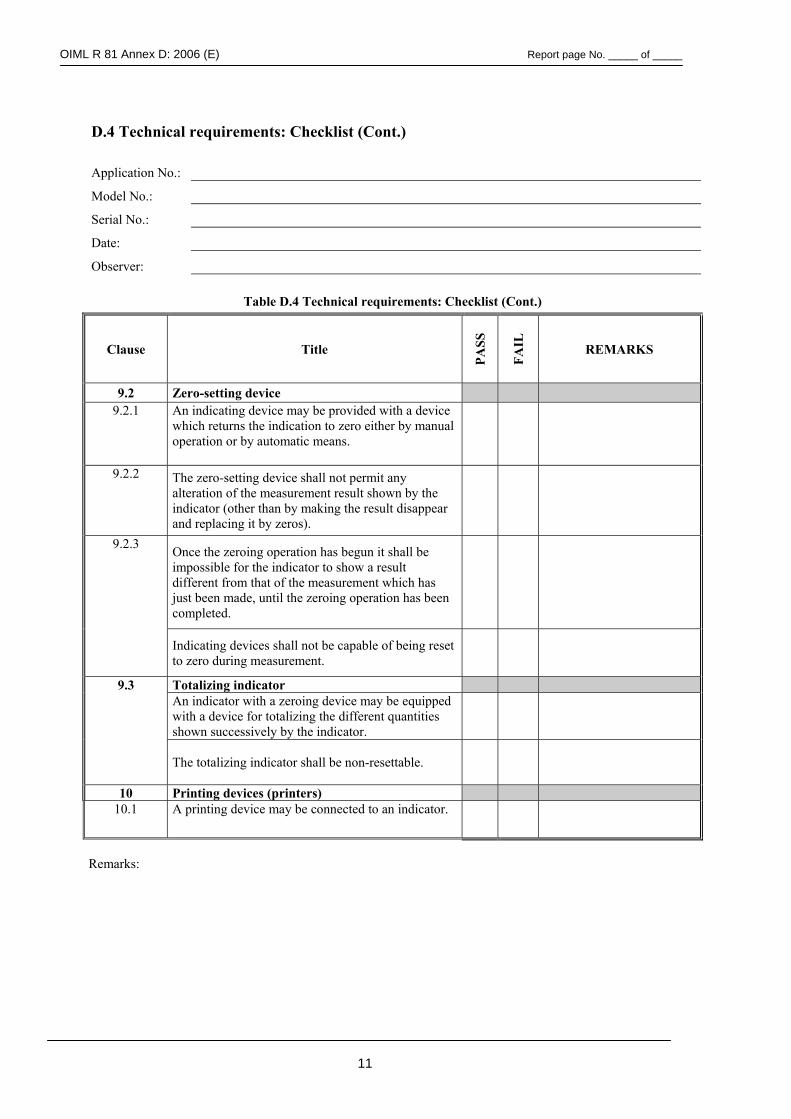
OIML R 81 Annex D: 2006 (E) Report page No. _____ of _____
11
D.4 Technical requirements: Checklist (Cont.)
Application No.:
Model No.:
Serial No.:
Date:
Observer:
Table D.4 Technical requirements: Checklist (Cont.)
Clause Title
PASS
FAIL
REMARKS
9.2 Zero-setting device 9.2.1 An indicating device may be provided with a device
which returns the indication to zero either by manual operation or by automatic means.
9.2.2 The zero-setting device shall not permit any alteration of the measurement result shown by the indicator (other than by making the result disappear and replacing it by zeros).
9.2.3 Once the zeroing operation has begun it shall be impossible for the indicator to show a result different from that of the measurement which has just been made, until the zeroing operation has been completed.
Indicating devices shall not be capable of being reset to zero during measurement.
Totalizing indicator 9.3 An indicator with a zeroing device may be equipped with a device for totalizing the different quantities shown successively by the indicator.
The totalizing indicator shall be non-resettable.
10 Printing devices (printers) 10.1 A printing device may be connected to an indicator.
Remarks:
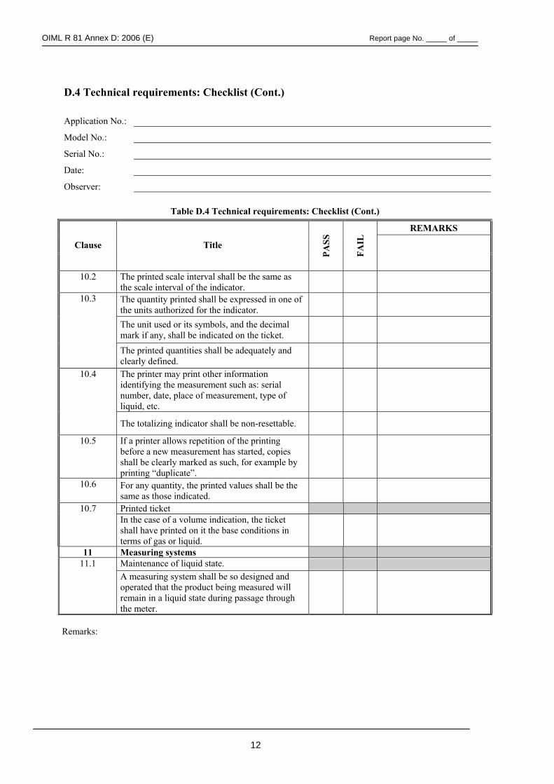
OIML R 81 Annex D: 2006 (E) Report page No. _____ of _____
12
D.4 Technical requirements: Checklist (Cont.)
Application No.:
Model No.:
Serial No.:
Date:
Observer:
Table D.4 Technical requirements: Checklist (Cont.)
REMARKS
Clause Title
PASS
FAIL
10.2 The printed scale interval shall be the same as the scale interval of the indicator.
10.3 The quantity printed shall be expressed in one of the units authorized for the indicator.
The unit used or its symbols, and the decimal mark if any, shall be indicated on the ticket.
The printed quantities shall be adequately and clearly defined.
10.4 The printer may print other information identifying the measurement such as: serial number, date, place of measurement, type of liquid, etc.
The totalizing indicator shall be non-resettable.
10.5 If a printer allows repetition of the printing before a new measurement has started, copies shall be clearly marked as such, for example by printing “duplicate”.
10.6 For any quantity, the printed values shall be the same as those indicated.
Printed ticket 10.7 In the case of a volume indication, the ticket shall have printed on it the base conditions in terms of gas or liquid.
11 Measuring systems Maintenance of liquid state. 11.1 A measuring system shall be so designed and operated that the product being measured will remain in a liquid state during passage through the meter.
Remarks:
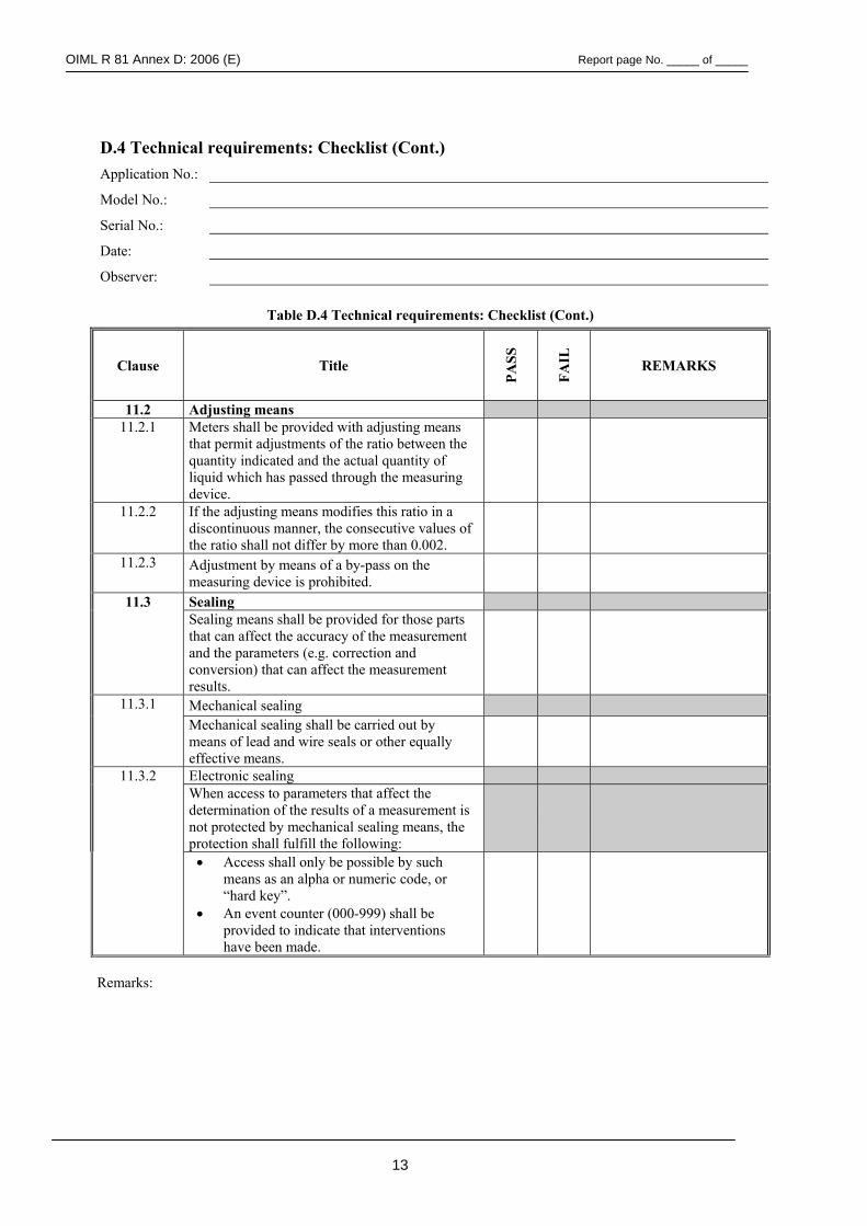
OIML R 81 Annex D: 2006 (E) Report page No. _____ of _____
13
D.4 Technical requirements: Checklist (Cont.) Application No.:
Model No.:
Serial No.:
Date:
Observer:
Table D.4 Technical requirements: Checklist (Cont.)
Clause Title PA
SS
FAIL
REMARKS
11.2 Adjusting means 11.2.1 Meters shall be provided with adjusting means
that permit adjustments of the ratio between the quantity indicated and the actual quantity of liquid which has passed through the measuring device.
11.2.2 If the adjusting means modifies this ratio in a discontinuous manner, the consecutive values of the ratio shall not differ by more than 0.002.
11.2.3 Adjustment by means of a by-pass on the measuring device is prohibited.
11.3 Sealing Sealing means shall be provided for those parts
that can affect the accuracy of the measurement and the parameters (e.g. correction and conversion) that can affect the measurement results.
11.3.1 Mechanical sealing Mechanical sealing shall be carried out by
means of lead and wire seals or other equally effective means.
Electronic sealing 11.3.2 When access to parameters that affect the determination of the results of a measurement is not protected by mechanical sealing means, the protection shall fulfill the following:
• Access shall only be possible by such means as an alpha or numeric code, or “hard key”.
• An event counter (000-999) shall be provided to indicate that interventions have been made.
Remarks:
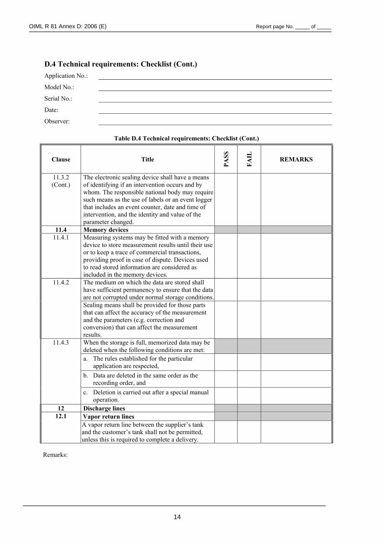
OIML R 81 Annex D: 2006 (E) Report page No. _____ of _____
14
D.4 Technical requirements: Checklist (Cont.) Application No.:
Model No.:
Serial No.:
Date:
Observer:
Table D.4 Technical requirements: Checklist (Cont.)
Clause Title PA
SS
FAIL
REMARKS
11.3.2 (Cont.)
The electronic sealing device shall have a means of identifying if an intervention occurs and by whom. The responsible national body may require such means as the use of labels or an event logger that includes an event counter, date and time of intervention, and the identity and value of the parameter changed.
11.4 Memory devices 11.4.1 Measuring systems may be fitted with a memory
device to store measurement results until their use or to keep a trace of commercial transactions, providing proof in case of dispute. Devices used to read stored information are considered as included in the memory devices.
The medium on which the data are stored shall have sufficient permanency to ensure that the data are not corrupted under normal storage conditions.
11.4.2
Sealing means shall be provided for those parts that can affect the accuracy of the measurement and the parameters (e.g. correction and conversion) that can affect the measurement results.
When the storage is full, memorized data may be deleted when the following conditions are met:
a. The rules established for the particular application are respected,
b. Data are deleted in the same order as the recording order, and
11.4.3
c. Deletion is carried out after a special manual operation.
12 Discharge lines Vapor return lines 12.1 A vapor return line between the supplier’s tank and the customer’s tank shall not be permitted, unless this is required to complete a delivery.
Remarks:
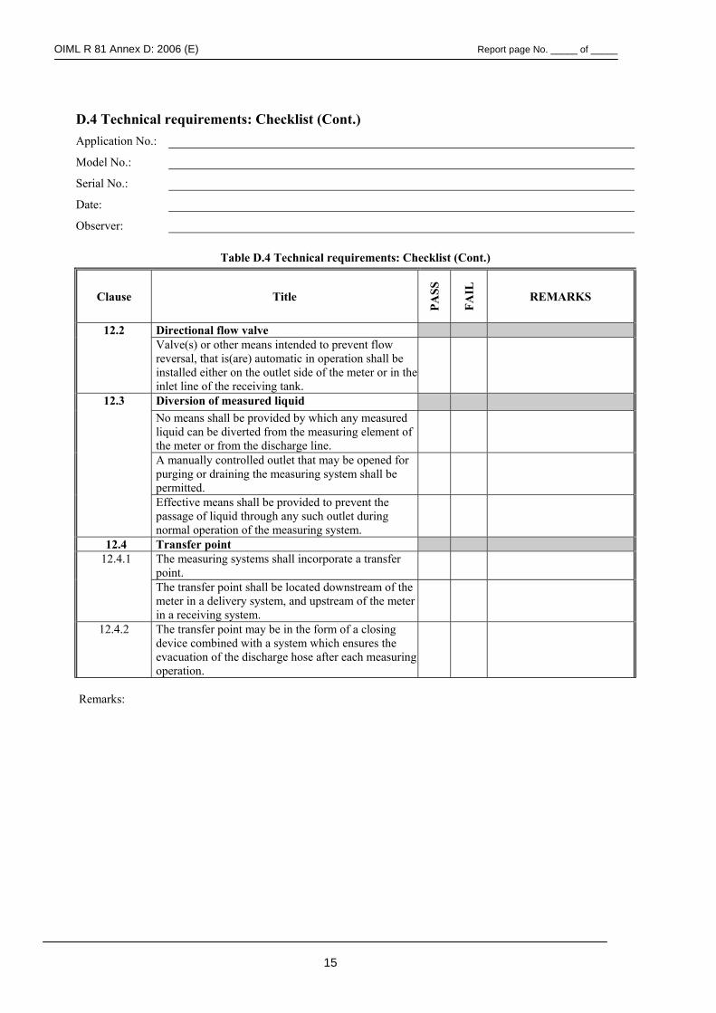
OIML R 81 Annex D: 2006 (E) Report page No. _____ of _____
15
D.4 Technical requirements: Checklist (Cont.) Application No.:
Model No.:
Serial No.:
Date:
Observer:
Table D.4 Technical requirements: Checklist (Cont.)
Clause Title
PASS
FAIL
REMARKS
Directional flow valve 12.2 Valve(s) or other means intended to prevent flow reversal, that is(are) automatic in operation shall be installed either on the outlet side of the meter or in the inlet line of the receiving tank.
Diversion of measured liquid No means shall be provided by which any measured liquid can be diverted from the measuring element of the meter or from the discharge line.
A manually controlled outlet that may be opened for purging or draining the measuring system shall be permitted.
12.3
Effective means shall be provided to prevent the passage of liquid through any such outlet during normal operation of the measuring system.
12.4 Transfer point The measuring systems shall incorporate a transfer point. 12.4.1
The transfer point shall be located downstream of the meter in a delivery system, and upstream of the meter in a receiving system.
12.4.2 The transfer point may be in the form of a closing device combined with a system which ensures the evacuation of the discharge hose after each measuring operation.
Remarks:
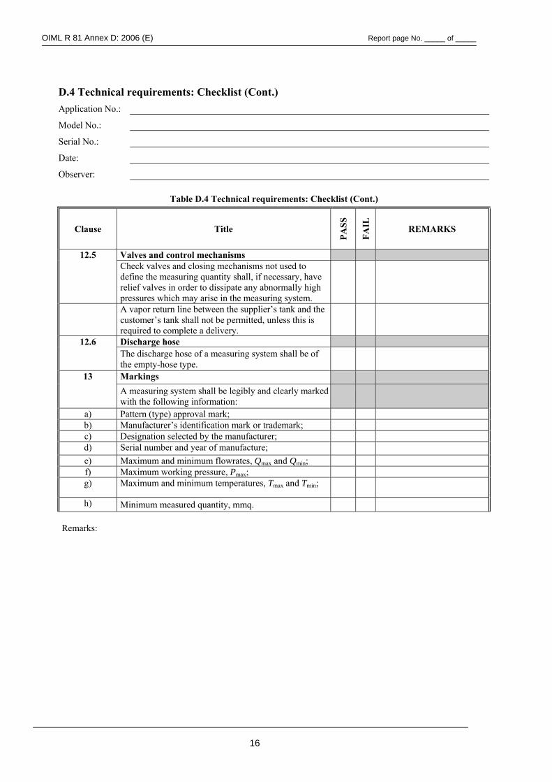
OIML R 81 Annex D: 2006 (E) Report page No. _____ of _____
16
D.4 Technical requirements: Checklist (Cont.) Application No.:
Model No.:
Serial No.:
Date:
Observer:
Table D.4 Technical requirements: Checklist (Cont.)
Clause Title
PASS
FAIL
REMARKS
12.5 Valves and control mechanisms Check valves and closing mechanisms not used to
define the measuring quantity shall, if necessary, have relief valves in order to dissipate any abnormally high pressures which may arise in the measuring system.
A vapor return line between the supplier’s tank and the customer’s tank shall not be permitted, unless this is required to complete a delivery.
12.6 Discharge hose The discharge hose of a measuring system shall be of
the empty-hose type.
13 Markings A measuring system shall be legibly and clearly marked
with the following information:
a) Pattern (type) approval mark; b) Manufacturer’s identification mark or trademark; c) Designation selected by the manufacturer; d) Serial number and year of manufacture; e) Maximum and minimum flowrates, Qmax and Qmin; f) Maximum working pressure, Pmax; g) Maximum and minimum temperatures, Tmax and Tmin;
h) Minimum measured quantity, mmq. Remarks:
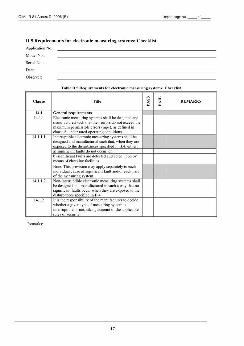
OIML R 81 Annex D: 2006 (E) Report page No. _____ of _____
17
D.5 Requirements for electronic measuring systems: Checklist Application No.:
Model No.:
Serial No.:
Date:
Observer:
Table D.5 Requirements for electronic measuring systems: Checklist
Clause Title
PASS
FAIL
REMARKS
14.1 General requirements 14.1.1 Electronic measuring systems shall be designed and
manufactured such that their errors do not exceed the maximum permissible errors (mpe), as defined in clause 6, under rated operating conditions.
14.1.1.1 Interruptible electronic measuring systems shall be designed and manufactured such that, when they are exposed to the disturbances specified in B.4, either:
a) significant faults do not occur, or b) significant faults are detected and acted upon by
means of checking facilities.
Note: This provision may apply separately to each individual cause of significant fault and/or each part of the measuring system.
14.1.1.2 Non-interruptible electronic measuring systems shall be designed and manufactured in such a way that no significant faults occur when they are exposed to the disturbances specified in B.4.
14.1.2 It is the responsibility of the manufacturer to decide whether a given type of measuring system is interruptible or not, taking account of the applicable rules of security.
Remarks:
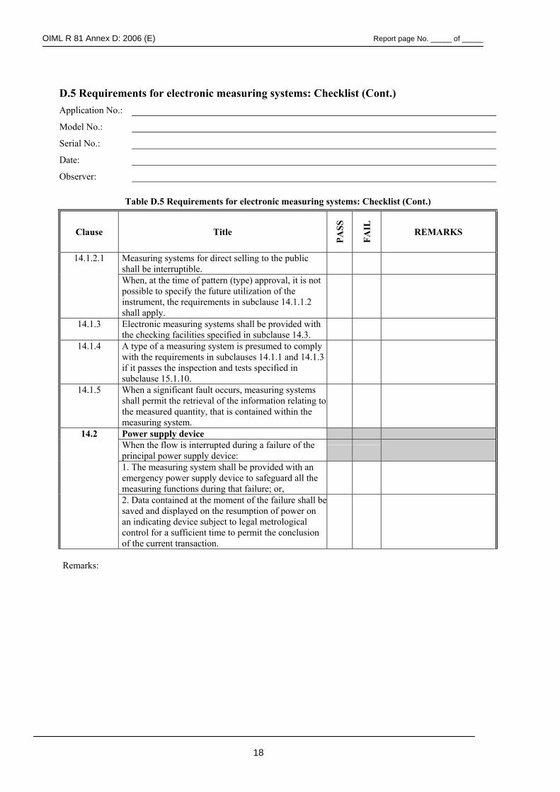
OIML R 81 Annex D: 2006 (E) Report page No. _____ of _____
18
D.5 Requirements for electronic measuring systems: Checklist (Cont.) Application No.:
Model No.:
Serial No.:
Date:
Observer:
Table D.5 Requirements for electronic measuring systems: Checklist (Cont.)
Clause Title
PASS
FAIL
REMARKS
14.1.2.1 Measuring systems for direct selling to the public shall be interruptible.
When, at the time of pattern (type) approval, it is not possible to specify the future utilization of the instrument, the requirements in subclause 14.1.1.2 shall apply.
14.1.3 Electronic measuring systems shall be provided with the checking facilities specified in subclause 14.3.
14.1.4 A type of a measuring system is presumed to comply with the requirements in subclauses 14.1.1 and 14.1.3 if it passes the inspection and tests specified in subclause 15.1.10.
14.1.5 When a significant fault occurs, measuring systems shall permit the retrieval of the information relating to the measured quantity, that is contained within the measuring system.
14.2 Power supply device When the flow is interrupted during a failure of the
principal power supply device:
1. The measuring system shall be provided with an emergency power supply device to safeguard all the measuring functions during that failure; or,
2. Data contained at the moment of the failure shall be saved and displayed on the resumption of power on an indicating device subject to legal metrological control for a sufficient time to permit the conclusion of the current transaction.
Remarks:
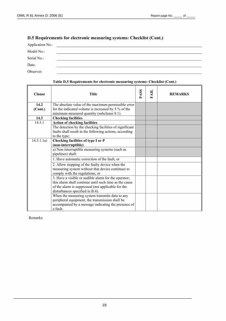
OIML R 81 Annex D: 2006 (E) Report page No. _____ of _____
19
D.5 Requirements for electronic measuring systems: Checklist (Cont.) Application No.:
Model No.:
Serial No.:
Date:
Observer:
Table D.5 Requirements for electronic measuring systems: Checklist (Cont.)
Clause Title
PASS
FAIL
REMARKS
14.2 (Cont.)
The absolute value of the maximum permissible error for the indicated volume is increased by 5 % of the minimum measured quantity (subclause 8.1).
14.3 Checking facilities 14.3.1 Action of checking facilities
The detection by the checking facilities of significant faults shall result in the following actions, according to the type:
14.3.1.1a) Checking facilities of type I or P (non-interruptible)
a) Non-interruptible measuring systems (such as pipelines) shall:
1. Have automatic correction of the fault, or 2. Allow stopping of the faulty device when the
measuring system without that device continues to comply with the regulations, or
3. Have a visible or audible alarm for the operator; this alarm shall continue until such time as the cause of the alarm is suppressed (not applicable for the disturbances specified in B.4).
When the measuring system transmits data to any peripheral equipment, the transmission shall be accompanied by a message indicating the presence of a fault.
Remarks:
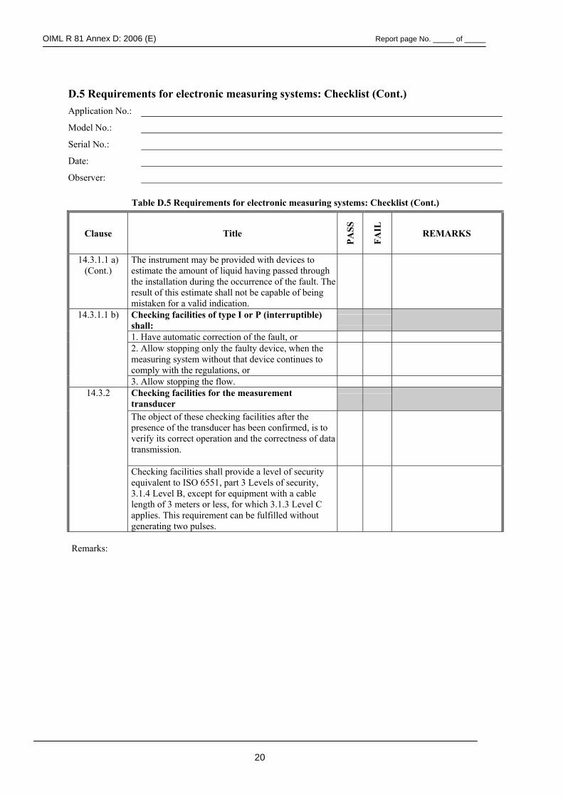
OIML R 81 Annex D: 2006 (E) Report page No. _____ of _____
20
D.5 Requirements for electronic measuring systems: Checklist (Cont.) Application No.:
Model No.:
Serial No.:
Date:
Observer:
Table D.5 Requirements for electronic measuring systems: Checklist (Cont.)
Clause Title
PASS
FAIL
REMARKS
14.3.1.1 a) (Cont.)
The instrument may be provided with devices to estimate the amount of liquid having passed through the installation during the occurrence of the fault. The result of this estimate shall not be capable of being mistaken for a valid indication.
14.3.1.1 b) Checking facilities of type I or P (interruptible) shall:
1. Have automatic correction of the fault, or
2. Allow stopping only the faulty device, when the measuring system without that device continues to comply with the regulations, or
3. Allow stopping the flow. 14.3.2 Checking facilities for the measurement
transducer
The object of these checking facilities after the presence of the transducer has been confirmed, is to verify its correct operation and the correctness of data transmission.
Checking facilities shall provide a level of security equivalent to ISO 6551, part 3 Levels of security, 3.1.4 Level B, except for equipment with a cable length of 3 meters or less, for which 3.1.3 Level C applies. This requirement can be fulfilled without generating two pulses.
Remarks:
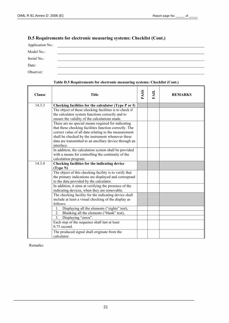
OIML R 81 Annex D: 2006 (E) Report page No. _____ of _____
21
D.5 Requirements for electronic measuring systems: Checklist (Cont.) Application No.:
Model No.:
Serial No.:
Date:
Observer:
Table D.5 Requirements for electronic measuring systems: Checklist (Cont.)
Clause Title
PASS
FAIL
REMARKS
14.3.3 Checking facilities for the calculator (Type P or I) The object of these checking facilities is to check if
the calculator system functions correctly and to ensure the validity of the calculations made.
There are no special means required for indicating that these checking facilities function correctly. The correct value of all data relating to the measurement shall be checked by the instrument whenever these data are transmitted to an ancillary device through an interface.
In addition, the calculation system shall be provided with a means for controlling the continuity of the calculation program.
14.3.4 Checking facilities for the indicating device (Type N)
The object of this checking facility is to verify that the primary indications are displayed and correspond to the data provided by the calculator.
In addition, it aims at verifying the presence of the indicating devices, when they are removable.
The checking facility for the indicating device shall include at least a visual checking of the display as follows:
1. Displaying all the elements (“eights” test), 2. Blanking all the elements (“blank” test), 3. Displaying “zeros”.
Each step of the sequence shall last at least 0.75 second.
The produced signal shall originate from the calculator.
Remarks:
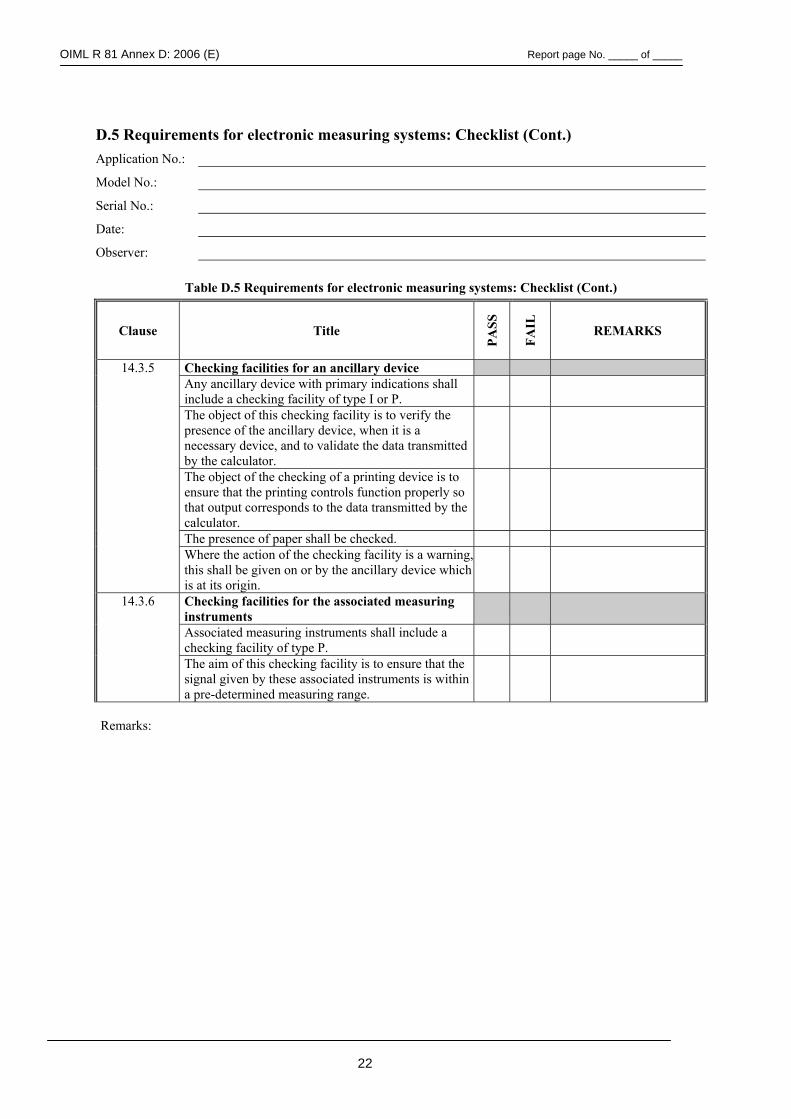
OIML R 81 Annex D: 2006 (E) Report page No. _____ of _____
22
D.5 Requirements for electronic measuring systems: Checklist (Cont.) Application No.:
Model No.:
Serial No.:
Date:
Observer:
Table D.5 Requirements for electronic measuring systems: Checklist (Cont.)
Clause Title
PASS
FAIL
REMARKS
14.3.5 Checking facilities for an ancillary device Any ancillary device with primary indications shall
include a checking facility of type I or P.
The object of this checking facility is to verify the presence of the ancillary device, when it is a necessary device, and to validate the data transmitted by the calculator.
The object of the checking of a printing device is to ensure that the printing controls function properly so that output corresponds to the data transmitted by the calculator.
The presence of paper shall be checked.
Where the action of the checking facility is a warning, this shall be given on or by the ancillary device which is at its origin.
14.3.6 Checking facilities for the associated measuring instruments
Associated measuring instruments shall include a checking facility of type P.
The aim of this checking facility is to ensure that the signal given by these associated instruments is within a pre-determined measuring range.
Remarks:
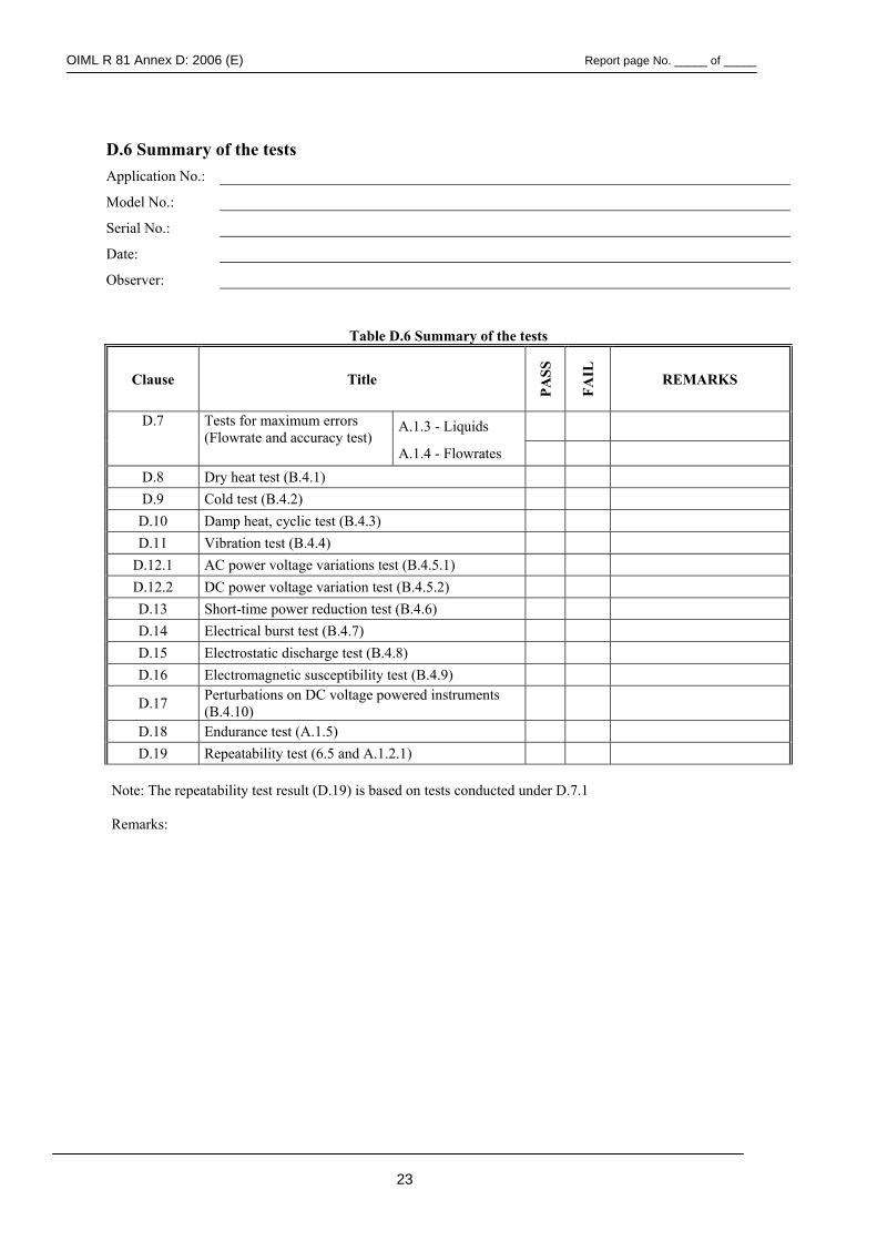
OIML R 81 Annex D: 2006 (E) Report page No. _____ of _____
23
D.6 Summary of the tests Application No.:
Model No.:
Serial No.:
Date:
Observer:
Table D.6 Summary of the tests
Clause Title
PASS
FAIL
REMARKS
D.7 A.1.3 - Liquids
Tests for maximum errors (Flowrate and accuracy test)
A.1.4 - Flowrates
D.8 Dry heat test (B.4.1) D.9 Cold test (B.4.2)
D.10 Damp heat, cyclic test (B.4.3) D.11 Vibration test (B.4.4)
D.12.1 AC power voltage variations test (B.4.5.1) D.12.2 DC power voltage variation test (B.4.5.2) D.13 Short-time power reduction test (B.4.6) D.14 Electrical burst test (B.4.7) D.15 Electrostatic discharge test (B.4.8) D.16 Electromagnetic susceptibility test (B.4.9)
D.17 Perturbations on DC voltage powered instruments (B.4.10)
D.18 Endurance test (A.1.5) D.19 Repeatability test (6.5 and A.1.2.1)
Note: The repeatability test result (D.19) is based on tests conducted under D.7.1 Remarks:
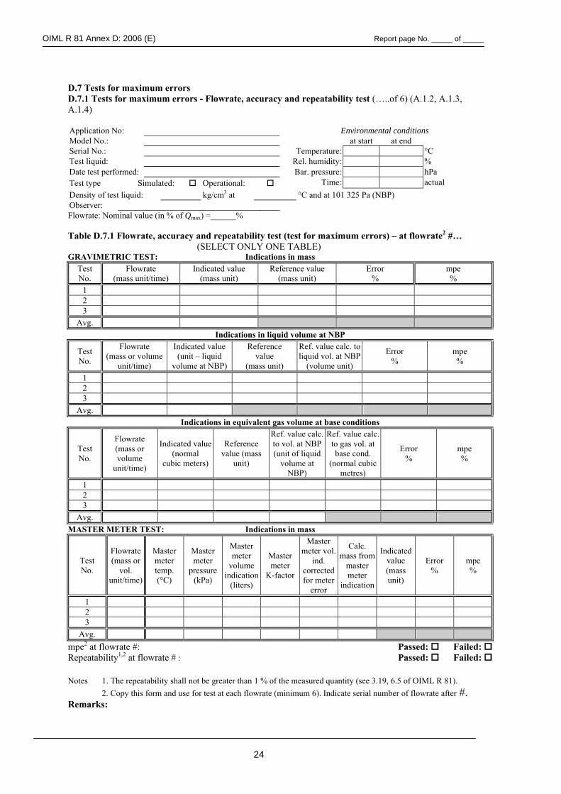
OIML R 81 Annex D: 2006 (E) Report page No. _____ of _____
24
D.7 Tests for maximum errors D.7.1 Tests for maximum errors - Flowrate, accuracy and repeatability test (…..of 6) (A.1.2, A.1.3, A.1.4) Application No: Environmental conditions Model No.: at start at end Serial No.: Temperature: °C Test liquid: Rel. humidity: % Date test performed: Bar. pressure: hPa Test type Simulated: Operational: Time: actual Density of test liquid: kg/cm3 at °C and at 101 325 Pa (NBP) Observer: Flowrate: Nominal value (in % of Qmax) =______% Table D.7.1 Flowrate, accuracy and repeatability test (test for maximum errors) – at flowrate2 #…
(SELECT ONLY ONE TABLE) GRAVIMETRIC TEST: Indications in mass
Test No.
Flowrate (mass unit/time)
Indicated value (mass unit)
Reference value (mass unit)
Error %
mpe %
1 2 3
Avg. Indications in liquid volume at NBP
Test No.
Flowrate (mass or volume
unit/time)
Indicated value (unit – liquid
volume at NBP)
Reference value
(mass unit)
Ref. value calc. to liquid vol. at NBP
(volume unit)
Error %
mpe %
1 2 3
Avg. Indications in equivalent gas volume at base conditions
Test No.
Flowrate (mass or volume
unit/time)
Indicated value (normal
cubic meters)
Reference value (mass
unit)
Ref. value calc. to vol. at NBP (unit of liquid
volume at NBP)
Ref. value calc. to gas vol. at base cond.
(normal cubic metres)
Error %
mpe %
1 2 3
Avg. MASTER METER TEST: Indications in mass
Test No.
Flowrate (mass or
vol. unit/time)
Master meter temp. (°C)
Master meter
pressure (kPa)
Master meter
volume indication
(liters)
Master meter
K-factor
Master meter vol.
ind. corrected for meter
error
Calc. mass from
master meter
indication
Indicated value (mass unit)
Error %
mpe %
1 2 3
Avg. mpe2 at flowrate #: Passed: Failed: Repeatability1,2 at flowrate # : Passed: Failed: Notes 1. The repeatability shall not be greater than 1 % of the measured quantity (see 3.19, 6.5 of OIML R 81).
2. Copy this form and use for test at each flowrate (minimum 6). Indicate serial number of flowrate after #. Remarks:
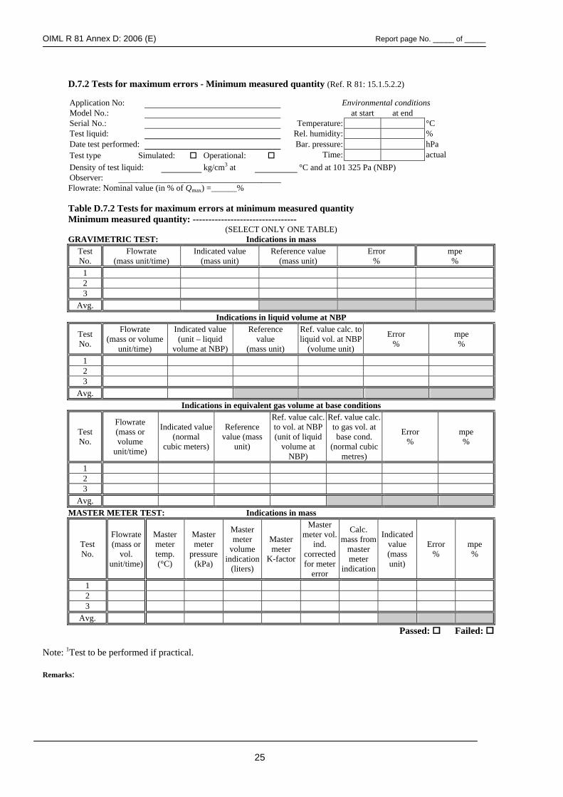
OIML R 81 Annex D: 2006 (E) Report page No. _____ of _____
25
D.7.2 Tests for maximum errors - Minimum measured quantity (Ref. R 81: 15.1.5.2.2)
Application No: Environmental conditions Model No.: at start at end Serial No.: Temperature: °C Test liquid: Rel. humidity: % Date test performed: Bar. pressure: hPa Test type Simulated: Operational: Time: actual Density of test liquid: kg/cm3 at °C and at 101 325 Pa (NBP) Observer: Flowrate: Nominal value (in % of Qmax) =______% Table D.7.2 Tests for maximum errors at minimum measured quantity Minimum measured quantity: ---------------------------------
(SELECT ONLY ONE TABLE) GRAVIMETRIC TEST: Indications in mass
Test No.
Flowrate (mass unit/time)
Indicated value (mass unit)
Reference value (mass unit)
Error %
mpe %
1 2 3
Avg. Indications in liquid volume at NBP
Test No.
Flowrate (mass or volume
unit/time)
Indicated value (unit – liquid
volume at NBP)
Reference value
(mass unit)
Ref. value calc. to liquid vol. at NBP
(volume unit)
Error %
mpe %
1 2 3
Avg. Indications in equivalent gas volume at base conditions
Test No.
Flowrate (mass or volume
unit/time)
Indicated value (normal
cubic meters)
Reference value (mass
unit)
Ref. value calc. to vol. at NBP (unit of liquid
volume at NBP)
Ref. value calc. to gas vol. at base cond.
(normal cubic metres)
Error %
mpe %
1 2 3
Avg. MASTER METER TEST: Indications in mass
Test No.
Flowrate (mass or
vol. unit/time)
Master meter temp. (°C)
Master meter
pressure (kPa)
Master meter
volume indication
(liters)
Master meter
K-factor
Master meter vol.
ind. corrected for meter
error
Calc. mass from
master meter
indication
Indicated value (mass unit)
Error %
mpe %
1 2 3
Avg. Passed: Failed: Note: 1Test to be performed if practical. Remarks:
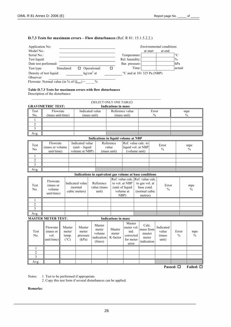
OIML R 81 Annex D: 2006 (E) Report page No. _____ of _____
26
D.7.3 Tests for maximum errors – Flow disturbances (Ref. R 81: 15.1.5.2.2.) Application No: Environmental conditions Model No.: at start at end Serial No.: Temperature: °C Test liquid: Rel. humidity: % Date test performed: Bar. pressure: hPa Test type Simulated: Operational: Time: actual Density of test liquid: kg/cm3 at °C and at 101 325 Pa (NBP) Observer: Flowrate: Normal value (in % of Qmax) = _____% Table D.7.3 Tests for maximum errors with flow disturbances Description of the disturbance: __________________________________________________________________________
(SELECT ONLY ONE TABLE) GRAVIMETRIC TEST: Indications in mass
Test No.
Flowrate (mass unit/time)
Indicated value (mass unit)
Reference value (mass unit)
Error %
mpe %
1 2 3
Avg. Indications in liquid volume at NBP
Test No.
Flowrate (mass or volume
unit/time)
Indicated value (unit – liquid
volume at NBP)
Reference value
(mass unit)
Ref. value calc. to liquid vol. at NBP
(volume unit)
Error %
mpe %
1 2 3
Avg. Indications in equivalent gas volume at base conditions
Test No.
Flowrate (mass or volume
unit/time)
Indicated value (normal
cubic meters)
Reference value (mass
unit)
Ref. value calc. to vol. at NBP (unit of liquid
volume at NBP)
Ref. value calc. to gas vol. at base cond.
(normal cubic metres)
Error %
mpe %
1 2 3
Avg. MASTER METER TEST: Indications in mass
Test No.
Flowrate (mass or
vol. unit/time)
Master meter temp. (°C)
Master meter
pressure (kPa)
Master meter
volume indication
(liters)
Master meter
K-factor
Master meter vol.
ind. corrected for meter
error
Calc. mass from
master meter
indication
Indicated value (mass unit)
Error %
mpe %
1 2 3
Avg. Passed: Failed:
Notes: 1. Test to be performed if appropriate. 2. Copy this test form if several disturbances can be applied. Remarks:
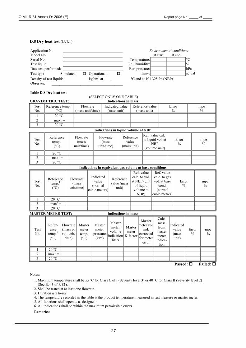
OIML R 81 Annex D: 2006 (E) Report page No. _____ of _____
27
D.8 Dry heat test (B.4.1) Application No: Environmental conditions Model No.: at start at end Serial No.: Temperature: °C Test liquid: Rel. humidity: % Date test performed: Bar. pressure: hPa Test type Simulated: Operational: Time: actual Density of test liquid: kg/cm3 at °C and at 101 325 Pa (NBP) Observer:
Table D.8 Dry heat test
(SELECT ONLY ONE TABLE) GRAVIMETRIC TEST: Indications in mass
Test No.
Reference temp.1 (°C)
Flowrate (mass unit/time)
Indicated value (mass unit)
Reference value (mass unit)
Error %
mpe %
1 20 °C 2 max1 = 3 20 °C
Indications in liquid volume at NBP
Test No.
Reference temp.1 (°C)
Flowrate (mass
unit/time)
Flowrate (mass
unit/time)
Reference value
(mass unit)
Ref. value calc. to liquid vol. at
NBP (volume unit)
Error %
mpe %
1 20 °C 2 max1 = 3 20 °C
Indications in equivalent gas volume at base conditions
Test No.
Reference temp.1 (°C)
Flowrate (mass
unit/time)
Indicated value
(normal cubic meters)
Reference value (mass
unit)
Ref. value calc. to vol. at NBP (unit
of liquid volume at
NBP)
Ref. value calc. to gas vol. at base
cond. (normal
cubic metres)
Error %
mpe %
1 20 °C 2 max1 = 3 20 °C
MASTER METER TEST: Indications in mass
Test No.
Refer-ence
temp.1 (°C)
Flowrate (mass or vol. unit/
time)
Master meter temp. (°C)
Master meter
pressure (kPa)
Master meter
volume indication
(liters)
Master meter
K-factor
Master meter vol.
ind. corrected for meter
error
Calc. mass from
master meter indica-
tion
Indicated value (mass unit)
Error %
mpe %
1 20 °C 2 max1 = 3 20 °C
Passed: Failed:
Notes: 1. Maximum temperature shall be 55 ºC for Class C of I (Severity level 3) or 40 ºC for Class B (Severity level 2)
(See B.4.3 of R 81). 2. Shall be tested at at least one flowrate. 3. Duration is 2 hours. 4. The temperature recorded in the table is the product temperature, measured in test measure or master meter. 5. All functions shall operate as designed. 6. All indications shall be within the maximum permissible errors. Remarks:
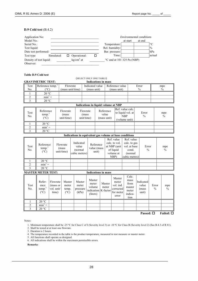
OIML R 81 Annex D: 2006 (E) Report page No. _____ of _____
28
D.9 Cold test (B.4.2) Application No: Environmental conditions Model No.: at start at end Serial No.: Temperature: °C Test liquid: Rel. humidity: % Date test performed: Bar. pressure: hPa Test type Simulated: Operational: Time: actual Density of test liquid: kg/cm3 at °C and at 101 325 Pa (NBP) Observer:
Table D.9 Cold test
(SELECT ONLY ONE TABLE) GRAVIMETRIC TEST: Indications in mass
Test No.
Reference temp.1 (°C)
Flowrate (mass unit/time)
Indicated value (mass unit)
Reference value (mass unit)
Error %
mpe %
1 20 °C 2 min1 = 3 20 °C
Indications in liquid volume at NBP
Test No.
Reference temp.1 (°C)
Flowrate (mass
unit/time)
Flowrate (mass
unit/time)
Reference value
(mass unit)
Ref. value calc. to liquid vol. at
NBP (volume unit)
Error %
mpe %
1 20 °C 2 min1 = 3 20 °C
Indications in equivalent gas volume at base conditions
Test No.
Reference temp.1 (°C)
Flowrate (mass
unit/time)
Indicated value
(normal cubic meters)
Reference value (mass
unit)
Ref. value calc. to vol. at NBP (unit
of liquid volume at
NBP)
Ref. value calc. to gas vol. at base
cond. (normal
cubic metres)
Error %
mpe %
1 20 °C 2 min1 = 3 20 °C
MASTER METER TEST: Indications in mass
Test No.
Refer-ence
temp.1 (°C)
Flowrate (mass or vol. unit/
time)
Master meter temp. (°C)
Master meter
pressure (kPa)
Master meter
volume indication
(liters)
Master meter
K-factor
Master meter
vol. ind. corrected for meter
error
Calc. mass from
master meter indica-
tion
Indicated value (mass unit)
Error %
mpe %
1 20 °C 2 min1 = 3 20 °C
Passed: Failed:
Notes: 1. Minimum temperature shall be -25 ºC for Class C of I (Severity level 3) or -10 ºC for Class B (Severity level 2) (See B.4.3 of R 81). 2. Shall be tested at at least one flowrate. 3. Duration is 2 hours. 4. The temperature recorded in the table is the product temperature, measured in test measure or master meter. 5. All functions shall operate as designed. 6. All indications shall be within the maximum permissible errors. Remarks:
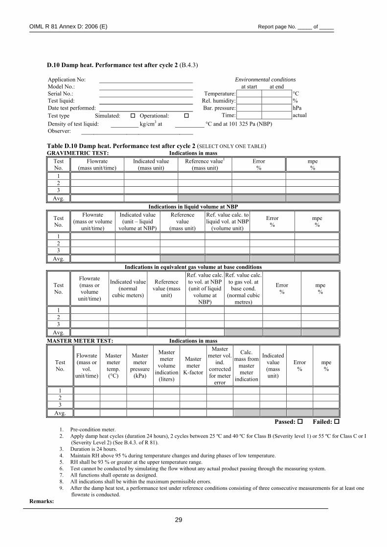
OIML R 81 Annex D: 2006 (E) Report page No. _____ of _____
29
D.10 Damp heat. Performance test after cycle 2 (B.4.3)
Application No: Environmental conditions Model No.: at start at end Serial No.: Temperature: °C Test liquid: Rel. humidity: % Date test performed: Bar. pressure: hPa Test type Simulated: Operational: Time: actual Density of test liquid: kg/cm3 at °C and at 101 325 Pa (NBP) Observer: Table D.10 Damp heat. Performance test after cycle 2 (SELECT ONLY ONE TABLE) GRAVIMETRIC TEST: Indications in mass
Test No.
Flowrate (mass unit/time)
Indicated value (mass unit)
Reference value1 (mass unit)
Error %
mpe %
1 2 3
Avg. Indications in liquid volume at NBP
Test No.
Flowrate (mass or volume
unit/time)
Indicated value (unit – liquid
volume at NBP)
Reference value
(mass unit)
Ref. value calc. to liquid vol. at NBP
(volume unit)
Error %
mpe %
1 2 3
Avg. Indications in equivalent gas volume at base conditions
Test No.
Flowrate (mass or volume
unit/time)
Indicated value (normal
cubic meters)
Reference value (mass
unit)
Ref. value calc. to vol. at NBP (unit of liquid
volume at NBP)
Ref. value calc. to gas vol. at base cond.
(normal cubic metres)
Error %
mpe %
1 2 3
Avg. MASTER METER TEST: Indications in mass
Test No.
Flowrate (mass or
vol. unit/time)
Master meter temp. (°C)
Master meter
pressure (kPa)
Master meter
volume indication
(liters)
Master meter
K-factor
Master meter vol.
ind. corrected for meter
error
Calc. mass from
master meter
indication
Indicated value (mass unit)
Error %
mpe %
1 2 3
Avg. Passed: Failed:
1. Pre-condition meter. 2. Apply damp heat cycles (duration 24 hours), 2 cycles between 25 ºC and 40 ºC for Class B (Severity level 1) or 55 ºC for Class C or I
(Severity Level 2) (See B.4.3. of R 81). 3. Duration is 24 hours. 4. Maintain RH above 95 % during temperature changes and during phases of low temperature. 5. RH shall be 93 % or greater at the upper temperature range. 6. Test cannot be conducted by simulating the flow without any actual product passing through the measuring system. 7. All functions shall operate as designed. 8. All indications shall be within the maximum permissible errors. 9. After the damp heat test, a performance test under reference conditions consisting of three consecutive measurements for at least one
flowrate is conducted. Remarks:
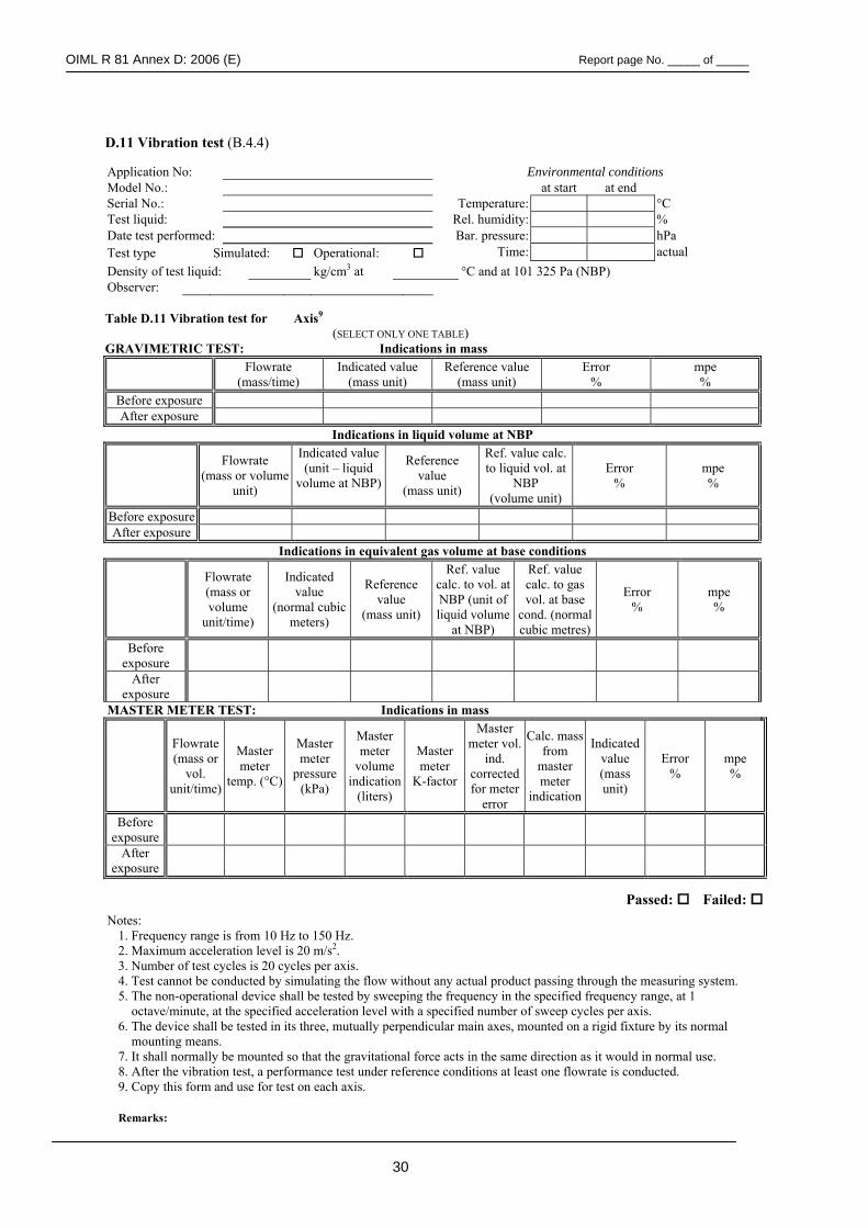
OIML R 81 Annex D: 2006 (E) Report page No. _____ of _____
30
D.11 Vibration test (B.4.4) Application No: Environmental conditions Model No.: at start at end Serial No.: Temperature: °C Test liquid: Rel. humidity: % Date test performed: Bar. pressure: hPa Test type Simulated: Operational: Time: actual Density of test liquid: kg/cm3 at °C and at 101 325 Pa (NBP) Observer: Table D.11 Vibration test for Axis9
(SELECT ONLY ONE TABLE) GRAVIMETRIC TEST: Indications in mass
Flowrate (mass/time)
Indicated value (mass unit)
Reference value (mass unit)
Error %
mpe %
Before exposure After exposure
Indications in liquid volume at NBP
Flowrate
(mass or volume unit)
Indicated value (unit – liquid
volume at NBP)
Reference value
(mass unit)
Ref. value calc. to liquid vol. at
NBP (volume unit)
Error %
mpe %
Before exposure After exposure
Indications in equivalent gas volume at base conditions
Flowrate (mass or volume
unit/time)
Indicated value
(normal cubic meters)
Reference value
(mass unit)
Ref. value calc. to vol. at NBP (unit of liquid volume
at NBP)
Ref. value calc. to gas vol. at base
cond. (normal cubic metres)
Error %
mpe %
Before exposure
After exposure
MASTER METER TEST: Indications in mass
Flowrate (mass or
vol. unit/time)
Master meter
temp. (°C)
Master meter
pressure (kPa)
Master meter
volume indication
(liters)
Master meter
K-factor
Master meter vol.
ind. corrected for meter
error
Calc. mass from
master meter
indication
Indicated value (mass unit)
Error %
mpe %
Before exposure
After exposure
Passed: Failed: Notes:
1. Frequency range is from 10 Hz to 150 Hz. 2. Maximum acceleration level is 20 m/s2. 3. Number of test cycles is 20 cycles per axis. 4. Test cannot be conducted by simulating the flow without any actual product passing through the measuring system. 5. The non-operational device shall be tested by sweeping the frequency in the specified frequency range, at 1
octave/minute, at the specified acceleration level with a specified number of sweep cycles per axis. 6. The device shall be tested in its three, mutually perpendicular main axes, mounted on a rigid fixture by its normal
mounting means. 7. It shall normally be mounted so that the gravitational force acts in the same direction as it would in normal use. 8. After the vibration test, a performance test under reference conditions at least one flowrate is conducted. 9. Copy this form and use for test on each axis.
Remarks:
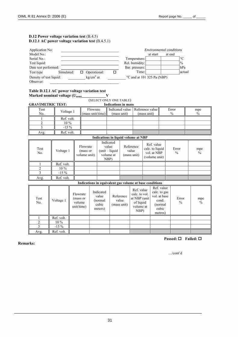
OIML R 81 Annex D: 2006 (E) Report page No. _____ of _____
31
D.12 Power voltage variation test (B.4.5) D.12.1 AC power voltage variation test (B.4.5.1) Application No: Environmental conditions Model No.: at start at end Serial No.: Temperature: °C Test liquid: Rel. humidity: % Date test performed: Bar. pressure: hPa Test type Simulated: Operational: Time: actual Density of test liquid: kg/cm3 at °C and at 101 325 Pa (NBP) Observer:
Table D.12.1 AC power voltage variation test Marked nominal voltage (Unom)____________V
(SELECT ONLY ONE TABLE) GRAVIMETRIC TEST: Indications in mass
Test No. Voltage 1 Flowrate
(mass unit/time)Indicated value
(mass unit) Reference value
(mass unit) Error
% mpe %
1 Ref. volt. 2 10 % 3 -15 %
Avg. Ref. volt. Indications in liquid volume at NBP
Test No. Voltage 1
Flowrate (mass or
volume unit)
Indicated value
(unit – liquid volume at
NBP)
Reference value
(mass unit)
Ref. value calc. to liquid vol. at NBP
(volume unit)
Error %
mpe %
1 Ref. volt. 2 10 % 3 -15 %
Avg. Ref. volt. Indications in equivalent gas volume at base conditions
Test No. Voltage 1
Flowrate (mass or volume
unit/time)
Indicated value
(normal cubic
meters)
Reference value
(mass unit)
Ref. value calc. to vol. at NBP (unit
of liquid volume at
NBP)
Ref. value calc. to gas vol. at base
cond. (normal cubic
metres)
Error %
mpe %
1 Ref. volt. 2 10 % 3 -15 %
Avg. Ref. volt.
Passed: Failed: Remarks:
…/cont’d
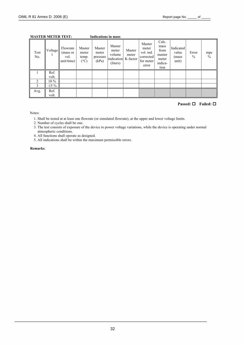
OIML R 81 Annex D: 2006 (E) Report page No. _____ of _____
32
MASTER METER TEST: Indications in mass
Test No.
Voltage 1
Flowrate (mass or
vol. unit/time)
Master meter temp. (°C)
Master meter
pressure (kPa)
Master meter
volume indication
(liters)
Master meter
K-factor
Master meter
vol. ind. corrected for meter
error
Calc. mass from
master meter indica-
tion
Indicated value (mass unit)
Error %
mpe %
1 Ref. volt.
2 10 % 3 -15 %
Avg. Ref. volt.
Passed: Failed: Notes:
1. Shall be tested at at least one flowrate (or simulated flowrate), at the upper and lower voltage limits. 2. Number of cycles shall be one. 3. The test consists of exposure of the device to power voltage variations, while the device is operating under normal
atmospheric conditions. 4. All functions shall operate as designed. 5. All indications shall be within the maximum permissible errors.
Remarks:
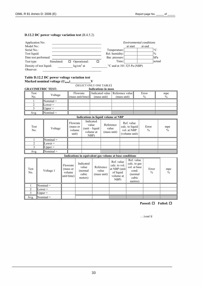
OIML R 81 Annex D: 2006 (E) Report page No. _____ of _____
33
D.12.2 DC power voltage variation test (B.4.5.2) Application No: Environmental conditions Model No.: at start at end Serial No.: Temperature: °C Test liquid: Rel. humidity: % Date test performed: Bar. pressure: hPa Test type Simulated: Operational: Time: actual Density of test liquid: kg/cm3 at °C and at 101 325 Pa (NBP) Observer: Table D.12.2 DC power voltage variation test Marked nominal voltage (Unom)____________V
(SELECT ONLY ONE TABLE) GRAVIMETRIC TEST: Indications in mass
Test No. Voltage Flowrate
(mass unit/time)Indicated value
(mass unit) Reference value
(mass unit) Error
% mpe %
1 Nominal = 2 Lower = 3 Upper =
Avg. Nominal = Indications in liquid volume at NBP
Test No. Voltage
Flowrate (mass or volume
unit)
Indicated value
(unit – liquid volume at
NBP)
Reference value
(mass unit)
Ref. value calc. to liquid vol. at NBP
(volume unit)
Error %
mpe %
1 Nominal = 2 Lower = 3 Upper =
Avg. Nominal = Indications in equivalent gas volume at base conditions
Test No. Voltage 1
Flowrate (mass or volume
unit/time)
Indicated value
(normal cubic
meters)
Reference value
(mass unit)
Ref. value calc. to vol. at NBP (unit
of liquid volume at
NBP)
Ref. value calc. to gas vol. at base
cond. (normal cubic
metres)
Error %
mpe %
1 Nominal = 2 Lower = 3 Upper =
Avg. Nominal =
Passed: Failed:
…/cont’d
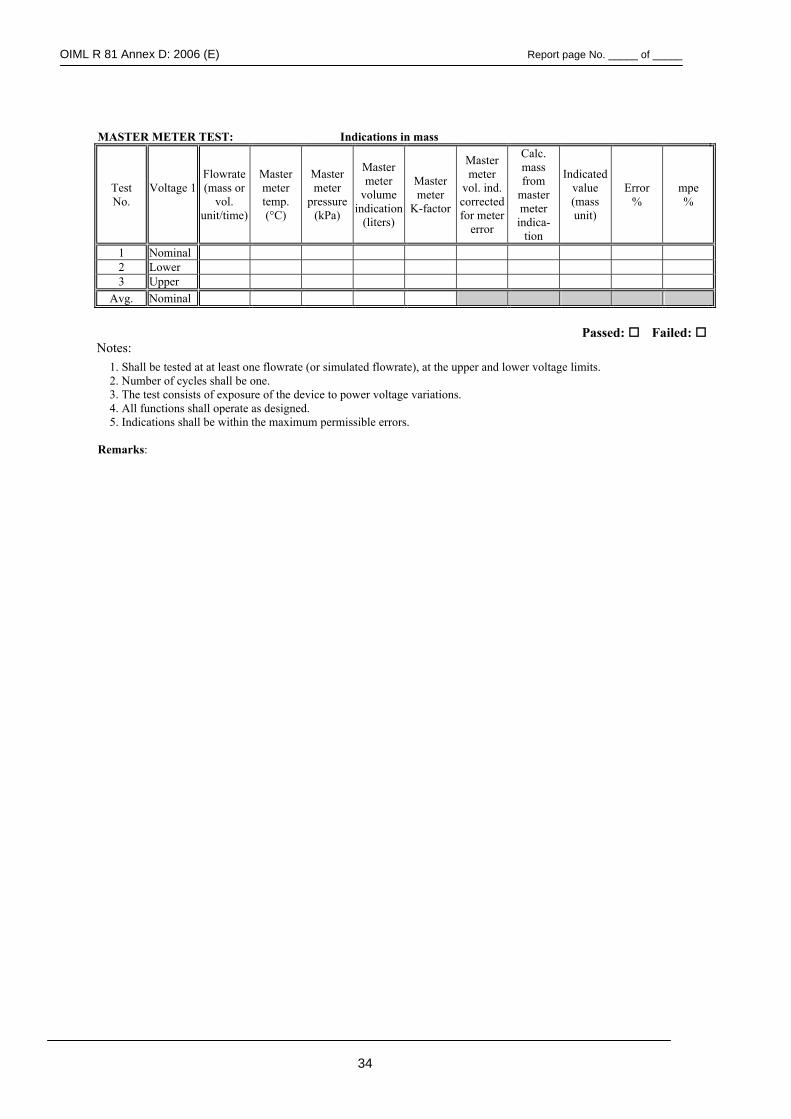
OIML R 81 Annex D: 2006 (E) Report page No. _____ of _____
34
MASTER METER TEST: Indications in mass
Test No.
Voltage 1
Flowrate (mass or
vol. unit/time)
Master meter temp. (°C)
Master meter
pressure (kPa)
Master meter
volume indication
(liters)
Master meter
K-factor
Master meter
vol. ind. corrected for meter
error
Calc. mass from
master meter indica-
tion
Indicated value (mass unit)
Error %
mpe %
1 Nominal 2 Lower 3 Upper
Avg. Nominal
Passed: Failed: Notes:
1. Shall be tested at at least one flowrate (or simulated flowrate), at the upper and lower voltage limits. 2. Number of cycles shall be one. 3. The test consists of exposure of the device to power voltage variations. 4. All functions shall operate as designed. 5. Indications shall be within the maximum permissible errors.
Remarks:
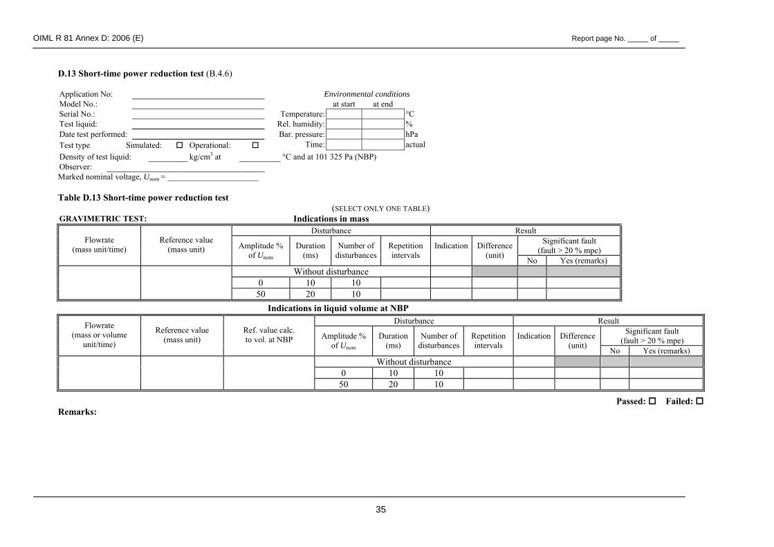
OIML R 81 Annex D: 2006 (E) Report page No. _____ of _____
35
D.13 Short-time power reduction test (B.4.6)
Application No: Environmental conditions Model No.: at start at end Serial No.: Temperature: °C Test liquid: Rel. humidity: % Date test performed: Bar. pressure: hPa Test type Simulated: Operational: Time: actual Density of test liquid: kg/cm3 at °C and at 101 325 Pa (NBP) Observer: Marked nominal voltage, Unom = ______________________ Table D.13 Short-time power reduction test
(SELECT ONLY ONE TABLE) GRAVIMETRIC TEST: Indications in mass
Disturbance Result Significant fault
(fault > 20 % mpe) Flowrate
(mass unit/time) Reference value
(mass unit) Amplitude % of Unom
Duration (ms)
Number of disturbances
Repetition intervals
Indication
Difference (unit) No Yes (remarks)
Without disturbance 0 10 10
50 20 10
Disturbance Result Significant fault
(fault > 20 % mpe)
Flowrate (mass or volume
unit/time)
Reference value (mass unit)
Ref. value calc. to vol. at NBP Amplitude %
of Unom Duration
(ms) Number of
disturbancesRepetition intervals
Indication
Difference (unit) No Yes (remarks)
Without disturbance 0 10 10
50 20 10
Passed: Failed: Remarks:
Indications in liquid volume at NBP
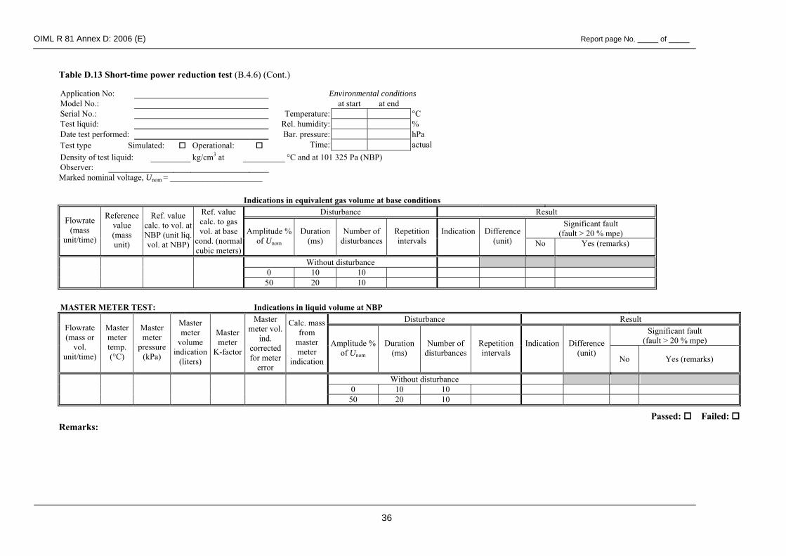
OIML R 81 Annex D: 2006 (E) Report page No. _____ of _____
36
Table D.13 Short-time power reduction test (B.4.6) (Cont.)
Application No: Environmental conditions Model No.: at start at end Serial No.: Temperature: °C Test liquid: Rel. humidity: % Date test performed: Bar. pressure: hPa Test type Simulated: Operational: Time: actual Density of test liquid: kg/cm3 at °C and at 101 325 Pa (NBP) Observer: Marked nominal voltage, Unom = ______________________
Indications in equivalent gas volume at base conditions
Disturbance Result Significant fault
(fault > 20 % mpe) Flowrate
(mass unit/time)
Reference value (mass unit)
Ref. value calc. to vol. at NBP (unit liq. vol. at NBP)
Ref. value calc. to gas vol. at base
cond. (normal cubic meters)
Amplitude %of Unom
Duration (ms)
Number of disturbances
Repetition intervals
Indication
Difference (unit) No Yes (remarks)
Without disturbance 0 10 10
50 20 10
MASTER METER TEST: Indications in liquid volume at NBP
Disturbance Result Significant fault
(fault > 20 % mpe) Flowrate (mass or
vol. unit/time)
Master meter temp. (°C)
Master meter
pressure (kPa)
Master meter
volume indication
(liters)
Master meter
K-factor
Master meter vol.
ind. corrected for meter
error
Calc. mass from
master meter
indication
Amplitude %of Unom
Duration (ms)
Number of disturbances
Repetition intervals
Indication
Difference (unit)
No Yes (remarks)
Without disturbance 0 10 10
50 20 10
Passed: Failed: Remarks:
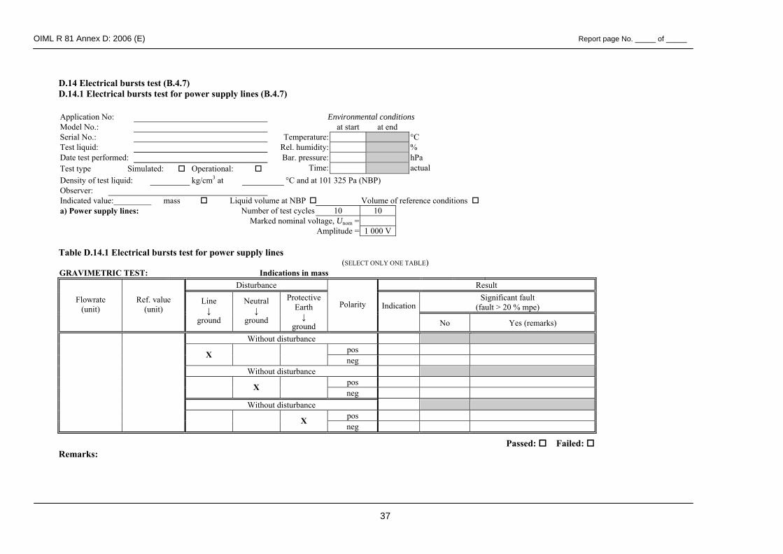
OIML R 81 Annex D: 2006 (E) Report page No. _____ of _____
37
D.14 Electrical bursts test (B.4.7) D.14.1 Electrical bursts test for power supply lines (B.4.7)
Application No: Environmental conditions Model No.: at start at end Serial No.: Temperature: °C Test liquid: Rel. humidity: % Date test performed: Bar. pressure: hPa Test type Simulated: Operational: Time: actual Density of test liquid: kg/cm3 at °C and at 101 325 Pa (NBP) Observer: Indicated value:_________ mass Liquid volume at NBP Volume of reference conditions a) Power supply lines: Number of test cycles 10 10 Marked nominal voltage, Unom = Amplitude = 1 000 V Table D.14.1 Electrical bursts test for power supply lines
(SELECT ONLY ONE TABLE) GRAVIMETRIC TEST: Indications in mass
Disturbance Result Significant fault
(fault > 20 % mpe) Flowrate
(unit) Ref. value
(unit) Line ↓
ground
Neutral ↓
ground
Protective Earth ↓
ground
Polarity Indication
No Yes (remarks)
Without disturbance pos X neg
Without disturbance pos X neg
Without disturbance pos
X neg
Passed: Failed: Remarks:
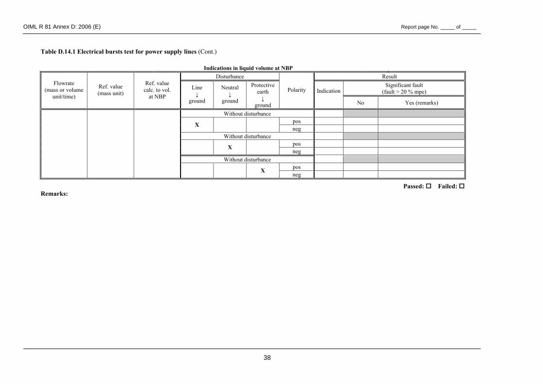
OIML R 81 Annex D: 2006 (E) Report page No. _____ of _____
38
Table D.14.1 Electrical bursts test for power supply lines (Cont.)
Indications in liquid volume at NBP Disturbance Result
Significant fault (fault > 20 % mpe)
Flowrate (mass or volume
unit/time)
Ref. value (mass unit)
Ref. value calc. to vol.
at NBP Line ↓
ground
Neutral ↓
ground
Protective earth ↓
ground
Polarity Indication
No Yes (remarks)
Without disturbance pos X neg
Without disturbance pos X neg
Without disturbance pos
X neg
Passed: Failed: Remarks:
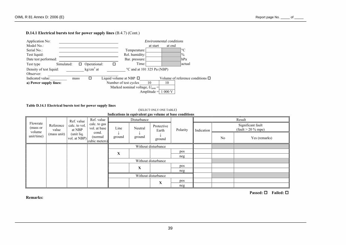
OIML R 81 Annex D: 2006 (E) Report page No. _____ of _____
39
D.14.1 Electrical bursts test for power supply lines (B.4.7) (Cont.) Application No: Environmental conditions Model No.: at start at end Serial No.: Temperature: °C Test liquid: Rel. humidity: % Date test performed: Bar. pressure: hPa Test type Simulated: Operational: Time: actual Density of test liquid: kg/cm3 at °C and at 101 325 Pa (NBP) Observer: Indicated value:_________ mass Liquid volume at NBP Volume of reference conditions a) Power supply lines: Number of test cycles 10 10 Marked nominal voltage, Unom = Amplitude = 1 000 V
Table D.14.1 Electrical bursts test for power supply lines (SELECT ONLY ONE TABLE)
Indications in equivalent gas volume at base conditions Disturbance Result
Significant fault (fault > 20 % mpe)
Flowrate (mass or volume
unit/time)
Reference value
(mass unit)
Ref. value calc. to vol.
at NBP (unit liq.
vol. at NBP)
Ref. value calc. to gas vol. at base
cond. (normal
cubic meters)
Line ↓
ground
Neutral ↓
ground
Protective Earth ↓
ground
Polarity Indication
No Yes (remarks)
Without disturbance pos X neg
Without disturbance pos X neg
Without disturbance pos
X neg
Passed: Failed: Remarks:
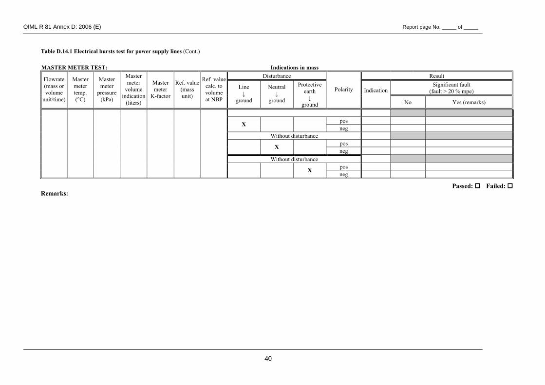
OIML R 81 Annex D: 2006 (E) Report page No. _____ of _____
40
Table D.14.1 Electrical bursts test for power supply lines (Cont.)
MASTER METER TEST: Indications in mass Disturbance Result
Significant fault (fault > 20 % mpe)
Flowrate (mass or volume
unit/time)
Master meter temp. (°C)
Master meter
pressure (kPa)
Master meter
volume indication
(liters)
Master meter
K-factor
Ref. value(mass unit)
Ref. valuecalc. to volume at NBP
Line ↓
ground
Neutral ↓
ground
Protective earth ↓
ground
Polarity Indication
No Yes (remarks)
pos X neg
Without disturbance pos X neg
Without disturbance pos
X neg
Passed: Failed: Remarks:
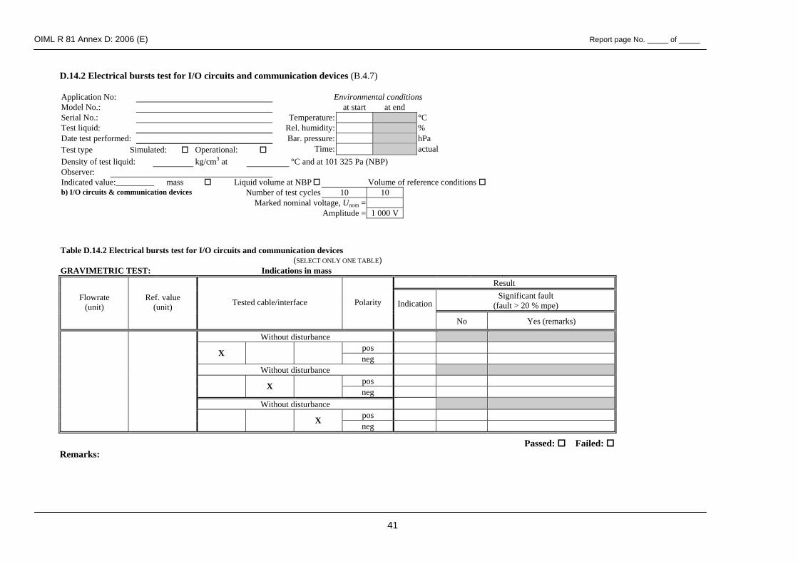
OIML R 81 Annex D: 2006 (E) Report page No. _____ of _____
41
D.14.2 Electrical bursts test for I/O circuits and communication devices (B.4.7) Application No: Environmental conditions Model No.: at start at end Serial No.: Temperature: °C Test liquid: Rel. humidity: % Date test performed: Bar. pressure: hPa Test type Simulated: Operational: Time: actual Density of test liquid: kg/cm3 at °C and at 101 325 Pa (NBP) Observer: Indicated value:_________ mass Liquid volume at NBP Volume of reference conditions b) I/O circuits & communication devices Number of test cycles 10 10 Marked nominal voltage, Unom = Amplitude = 1 000 V
Table D.14.2 Electrical bursts test for I/O circuits and communication devices (SELECT ONLY ONE TABLE)
GRAVIMETRIC TEST: Indications in mass Result
Significant fault (fault > 20 % mpe)
Flowrate (unit)
Ref. value (unit) Tested cable/interface Polarity Indication
No Yes (remarks)
Without disturbance pos X neg
Without disturbance pos X neg
Without disturbance pos
X neg
Passed: Failed: Remarks:
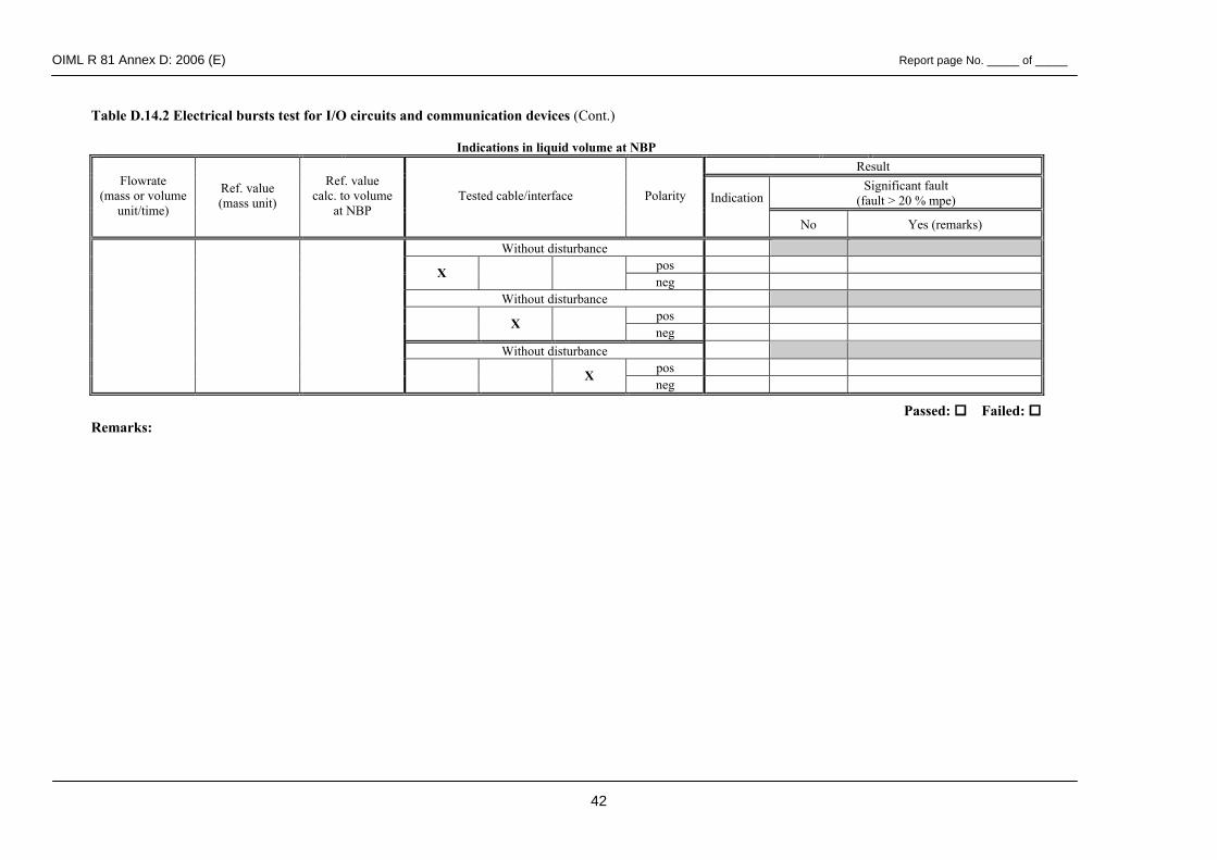
OIML R 81 Annex D: 2006 (E) Report page No. _____ of _____
42
Table D.14.2 Electrical bursts test for I/O circuits and communication devices (Cont.) Indications in liquid volume at NBP
Result Significant fault
(fault > 20 % mpe) Flowrate
(mass or volume unit/time)
Ref. value (mass unit)
Ref. value calc. to volume
at NBP Tested cable/interface Polarity Indication
No Yes (remarks)
Without disturbance pos X neg
Without disturbance pos X neg
Without disturbance pos
X neg
Passed: Failed: Remarks:
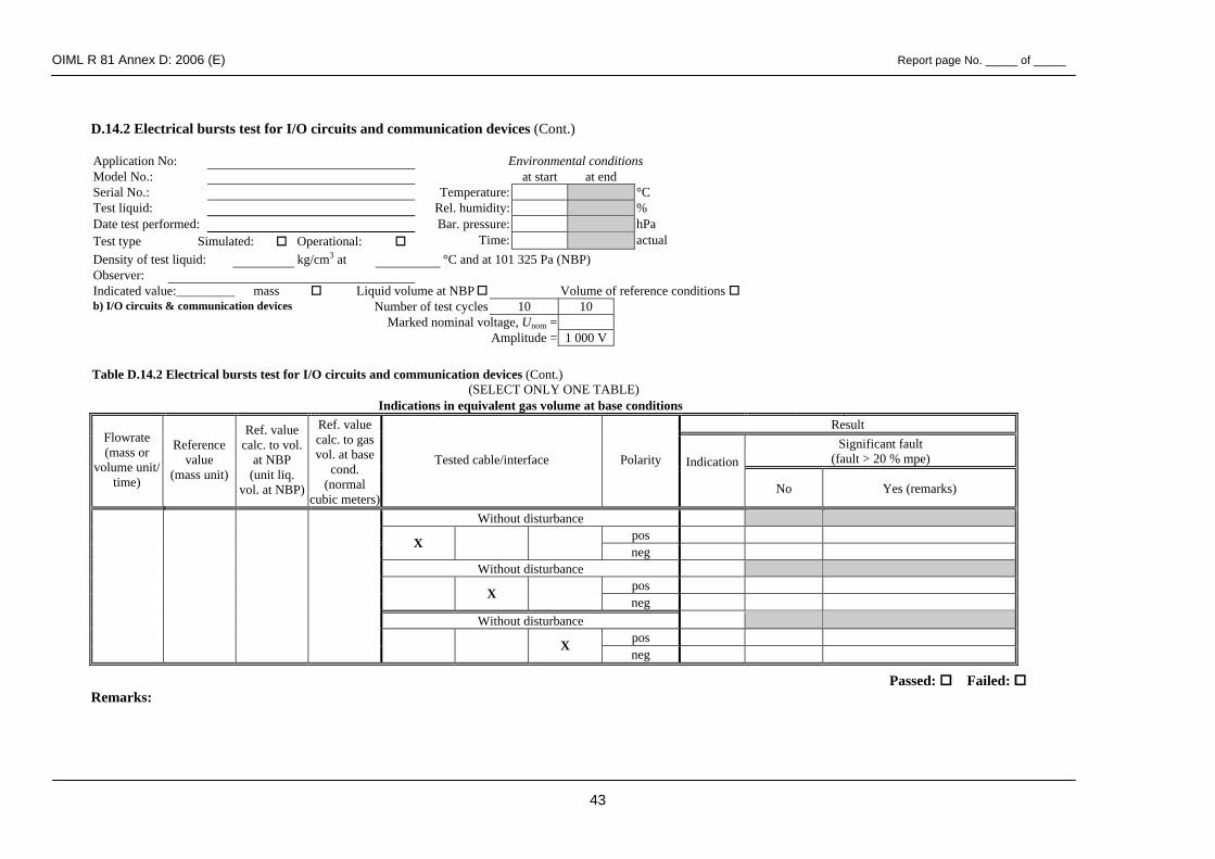
OIML R 81 Annex D: 2006 (E) Report page No. _____ of _____
43
D.14.2 Electrical bursts test for I/O circuits and communication devices (Cont.) Application No: Environmental conditions Model No.: at start at end Serial No.: Temperature: °C Test liquid: Rel. humidity: % Date test performed: Bar. pressure: hPa Test type Simulated: Operational: Time: actual Density of test liquid: kg/cm3 at °C and at 101 325 Pa (NBP) Observer: Indicated value:_________ mass Liquid volume at NBP Volume of reference conditions b) I/O circuits & communication devices Number of test cycles 10 10 Marked nominal voltage, Unom = Amplitude = 1 000 V
Table D.14.2 Electrical bursts test for I/O circuits and communication devices (Cont.)
(SELECT ONLY ONE TABLE) Indications in equivalent gas volume at base conditions
Result Significant fault
(fault > 20 % mpe)
Flowrate (mass or
volume unit/ time)
Reference value
(mass unit)
Ref. value calc. to vol.
at NBP (unit liq.
vol. at NBP)
Ref. value calc. to gas vol. at base
cond. (normal
cubic meters)
Tested cable/interface Polarity Indication
No Yes (remarks)
Without disturbance pos X neg
Without disturbance pos X neg
Without disturbance pos
X neg
Passed: Failed: Remarks:

OIML R 81 Annex D: 2006 (E) Report page No. _____ of _____
44
MASTER METER TEST: Indications in mass
Result Significant fault
(fault > 20 % mpe)
Flowrate (mass or
vol. unit/time)
Master meter temp. (°C)
Master meter
pressure (kPa)
Master meter
volume indication
(liters)
Master meter
K-factor
Ref. value(mass unit)
Ref. valuecalc. to volume at NBP
Tested cable/interface Polarity Indication
No Yes (remarks)
pos X neg
Without disturbance pos X neg
Without disturbance pos
X neg
Passed: Failed Remarks:
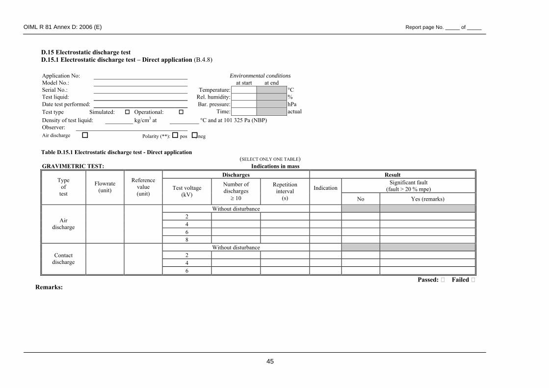
OIML R 81 Annex D: 2006 (E) Report page No. _____ of _____
45
D.15 Electrostatic discharge test D.15.1 Electrostatic discharge test – Direct application (B.4.8)
Application No: Environmental conditions Model No.: at start at end Serial No.: Temperature: °C Test liquid: Rel. humidity: % Date test performed: Bar. pressure: hPa Test type Simulated: Operational: Time: actual Density of test liquid: kg/cm3 at °C and at 101 325 Pa (NBP) Observer: Air discharge Polarity (**): pos neg
Table D.15.1 Electrostatic discharge test - Direct application
(SELECT ONLY ONE TABLE) GRAVIMETRIC TEST: Indications in mass
Discharges Result Significant fault
(fault > 20 % mpe) Type
of test
Flowrate (unit)
Reference value (unit)
Test voltage (kV)
Number of discharges
≥ 10
Repetition interval
(s)
Indication
No Yes (remarks)
Without disturbance 2 4 6
Air discharge
8 Without disturbance
2 4
Contact discharge
6 Passed: Failed
Remarks:
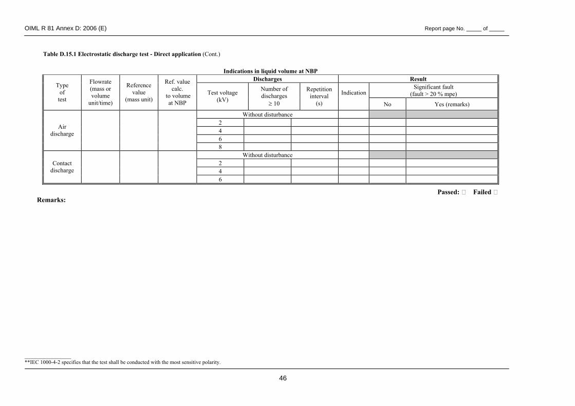
OIML R 81 Annex D: 2006 (E) Report page No. _____ of _____
46
Table D.15.1 Electrostatic discharge test - Direct application (Cont.)
Passed: Failed Remarks:
_________________ **IEC 1000-4-2 specifies that the test shall be conducted with the most sensitive polarity.
Indications in liquid volume at NBP Discharges Result
Significant fault (fault > 20 % mpe)
Type of
test
Flowrate (mass or volume
unit/time)
Reference value
(mass unit)
Ref. value calc.
to volume at NBP
Test voltage (kV)
Number of discharges
≥ 10
Repetition interval
(s)
Indication
No Yes (remarks)
Without disturbance 2 4 6
Air discharge
8 Without disturbance
2 4
Contact discharge
6
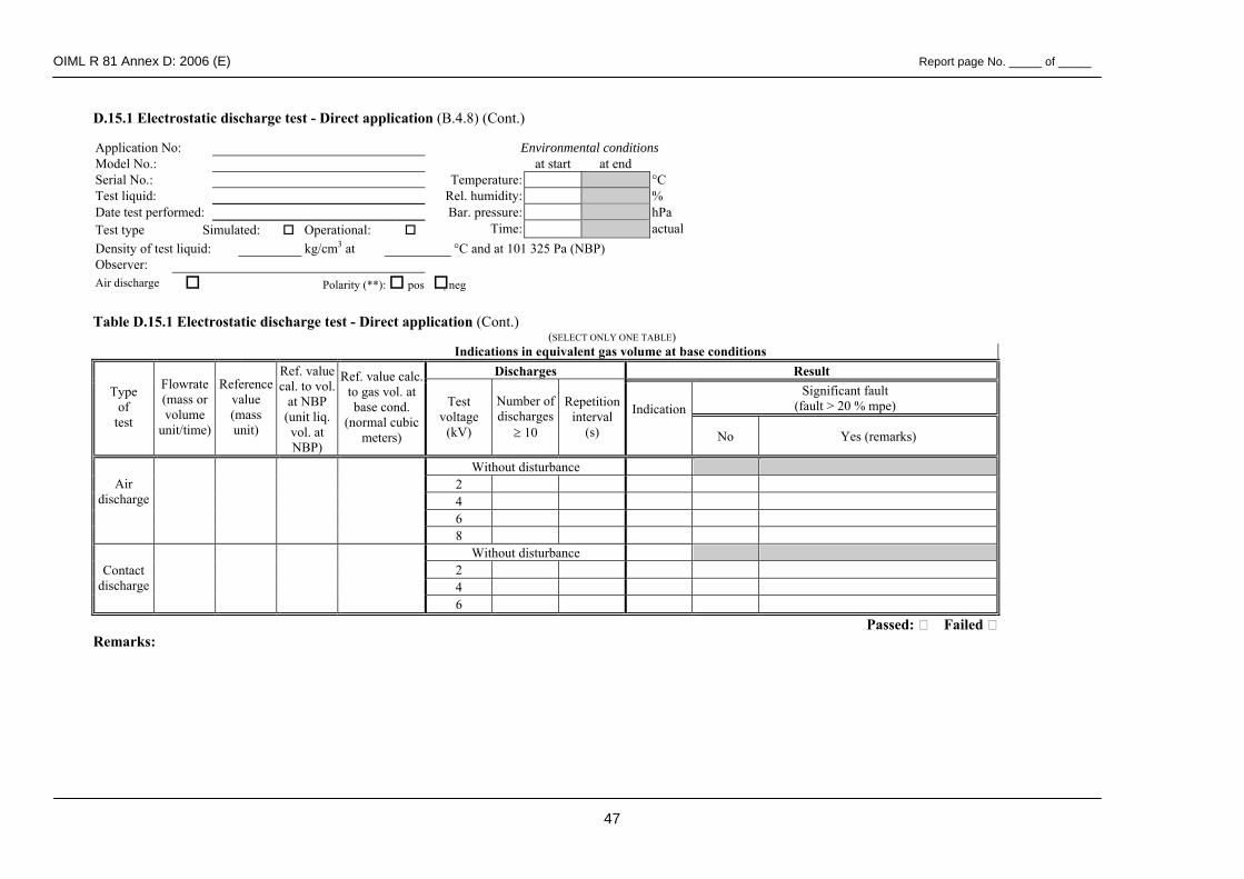
OIML R 81 Annex D: 2006 (E) Report page No. _____ of _____
47
D.15.1 Electrostatic discharge test - Direct application (B.4.8) (Cont.)
Application No: Environmental conditions Model No.: at start at end Serial No.: Temperature: °C Test liquid: Rel. humidity: % Date test performed: Bar. pressure: hPa Test type Simulated: Operational: Time: actual Density of test liquid: kg/cm3 at °C and at 101 325 Pa (NBP) Observer: Air discharge Polarity (**): pos neg
Table D.15.1 Electrostatic discharge test - Direct application (Cont.)
(SELECT ONLY ONE TABLE) Indications in equivalent gas volume at base conditions
Discharges Result Significant fault
(fault > 20 % mpe) Type
of test
Flowrate (mass or volume
unit/time)
Reference value (mass unit)
Ref. value cal. to vol.
at NBP (unit liq. vol. at NBP)
Ref. value calc. to gas vol. at base cond.
(normal cubic meters)
Test voltage
(kV)
Number of discharges
≥ 10
Repetitioninterval
(s)
Indication
No Yes (remarks)
Without disturbance 2 4 6
Air discharge
8 Without disturbance
2 4
Contact discharge
6 Passed: Failed
Remarks:
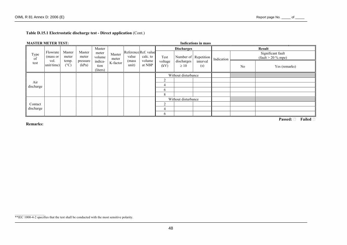
OIML R 81 Annex D: 2006 (E) Report page No. _____ of _____
48
Table D.15.1 Electrostatic discharge test - Direct application (Cont.)
MASTER METER TEST: Indications in mass Discharges Result
Significant fault (fault > 20 % mpe)
Type of
test
Flowrate (mass or
vol. unit/time)
Master meter temp. (°C)
Master meter
pressure (kPa)
Master meter
volume indica-
tion (liters)
Master meter
K-factor
Reference value (mass unit)
Ref. valuecalc. to volume at NBP
Test voltage
(kV)
Number of discharges
≥ 10
Repetitioninterval
(s)
Indication
No Yes (remarks)
Without disturbance 2 4 6
Air discharge
8 Without disturbance
2 4
Contact discharge
6 Passed: Failed
Remarks: __________________ **IEC 1000-4-2 specifies that the test shall be conducted with the most sensitive polarity.
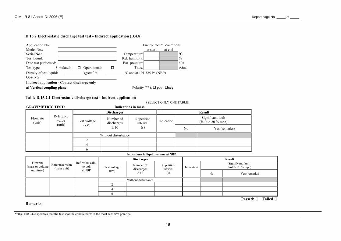
OIML R 81 Annex D: 2006 (E) Report page No. _____ of _____
49
D.15.2 Electrostatic discharge test test - Indirect application (B.4.8) Application No: Environmental conditions Model No.: at start at end Serial No.: Temperature: °C Test liquid: Rel. humidity: % Date test performed: Bar. pressure: hPa Test type Simulated: Operational: Time: actual Density of test liquid: kg/cm3 at °C and at 101 325 Pa (NBP) Observer: Indirect application - Contact discharge only a) Vertical coupling plane Polarity (**): pos neg
Table D.15.2.1 Electrostatic discharge test - Indirect application
(SELECT ONLY ONE TABLE) GRAVIMETRIC TEST: Indications in mass
Discharges Result Significant fault
(fault > 20 % mpe) Flowrate
(unit)
Reference value (unit)
Test voltage (kV)
Number of discharges
≥ 10
Repetition interval
(s)
Indication
No Yes (remarks)
Without disturbance 2 4
6 Indications in liquid volume at NBP
Discharges Result Significant fault
(fault > 20 % mpe) Flowrate
(mass or volume unit/time)
Reference value (mass unit)
Ref. value calc. to vol. at NBP
Test voltage (kV)
Number of discharges
≥ 10
Repetition interval
(s)
Indication
No Yes (remarks)
Without disturbance 2 4
6
Passed: Failed Remarks:
**IEC 1000-4-2 specifies that the test shall be conducted with the most sensitive polarity.
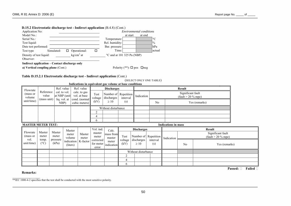
OIML R 81 Annex D: 2006 (E) Report page No. _____ of _____
50
D.15.2 Electrostatic discharge test - Indirect application (B.4.8) (Cont.) Application No: Environmental conditions Model No.: at start at end Serial No.: Temperature: °C Test liquid: Rel. humidity: % Date test performed: Bar. pressure: hPa Test type Simulated: Operational: Time: actual Density of test liquid: kg/cm3 at °C and at 101 325 Pa (NBP) Observer: Indirect application – Contact discharge only a) Vertical coupling plane (Cont.) Polarity (**): pos neg
Table D.15.2.1 Electrostatic discharge test - Indirect application (Cont.)
(SELECT ONLY ONE TABLE) Indications in equivalent gas volume at base conditions
Discharges Result Significant fault
(fault > 20 % mpe)
Flowrate (mass or volume
unit/time)
Reference value
(mass unit)
Ref. value cal. to vol.
at NBP (unit liq. vol. at
NBP)
Ref. value calc. to gas vol. at base
cond. (normal cubic meters)
Test voltage
(kV)
Number of discharges
≥ 10
Repetitioninterval
(s)
Indication
No Yes (remarks)
Without disturbance 2 4
6 MASTER METER TEST: Indications in mass
Discharges Result Significant fault
(fault > 20 % mpe) Flowrate (mass or
vol. unit/time)
Master meter temp. (°C)
Master meter
pressure (kPa)
Master meter
volume indication
(liters)
Master meter
K-factor
Vol. ind. master meter
corrected for meter
error
Calc. mass from
master meter
indication
Test voltage
(kV)
Number of discharges
≥ 10
Repetition interval
(s)
Indication
No Yes (remarks)
Without disturbance 2 4 6
Passed: Failed Remarks:
________________ **IEC 1000-4-2 specifies that the test shall be conducted with the most sensitive polarity.
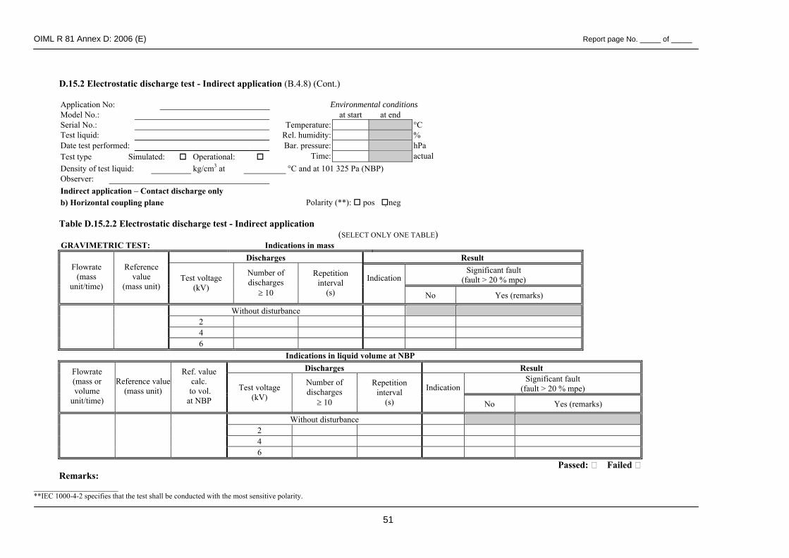
OIML R 81 Annex D: 2006 (E) Report page No. _____ of _____
51
D.15.2 Electrostatic discharge test - Indirect application (B.4.8) (Cont.) Application No: Environmental conditions Model No.: at start at end Serial No.: Temperature: °C Test liquid: Rel. humidity: % Date test performed: Bar. pressure: hPa Test type Simulated: Operational: Time: actual Density of test liquid: kg/cm3 at °C and at 101 325 Pa (NBP) Observer: Indirect application – Contact discharge only b) Horizontal coupling plane Polarity (**): pos neg Table D.15.2.2 Electrostatic discharge test - Indirect application
(SELECT ONLY ONE TABLE) GRAVIMETRIC TEST: Indications in mass
Discharges Result Significant fault
(fault > 20 % mpe) Flowrate
(mass unit/time)
Reference value
(mass unit) Test voltage
(kV)
Number of discharges
≥ 10
Repetition interval
(s)
Indication
No Yes (remarks)
Without disturbance 2 4
6 Indications in liquid volume at NBP
Discharges Result Significant fault
(fault > 20 % mpe)
Flowrate (mass or volume
unit/time)
Reference value (mass unit)
Ref. value calc.
to vol. at NBP
Test voltage (kV)
Number of discharges
≥ 10
Repetition interval
(s)
Indication
No Yes (remarks)
Without disturbance 2 4
6 Passed: Failed
Remarks: __________________ **IEC 1000-4-2 specifies that the test shall be conducted with the most sensitive polarity.
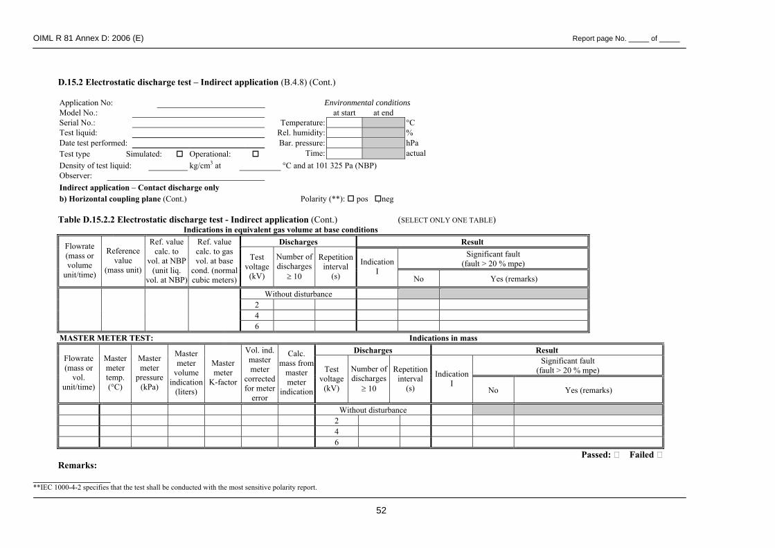
OIML R 81 Annex D: 2006 (E) Report page No. _____ of _____
52
D.15.2 Electrostatic discharge test – Indirect application (B.4.8) (Cont.) Application No: Environmental conditions Model No.: at start at end Serial No.: Temperature: °C Test liquid: Rel. humidity: % Date test performed: Bar. pressure: hPa Test type Simulated: Operational: Time: actual Density of test liquid: kg/cm3 at °C and at 101 325 Pa (NBP) Observer: Indirect application – Contact discharge only b) Horizontal coupling plane (Cont.) Polarity (**): pos neg Table D.15.2.2 Electrostatic discharge test - Indirect application (Cont.) (SELECT ONLY ONE TABLE) Indications in equivalent gas volume at base conditions
Discharges Result Significant fault
(fault > 20 % mpe)
Flowrate (mass or volume
unit/time)
Reference value
(mass unit)
Ref. value calc. to
vol. at NBP (unit liq.
vol. at NBP)
Ref. value calc. to gas vol. at base
cond. (normal cubic meters)
Test voltage
(kV)
Number of discharges
≥ 10
Repetitioninterval
(s)
IndicationI
No Yes (remarks)
Without disturbance 2 4
6 MASTER METER TEST: Indications in mass
Discharges Result Significant fault
(fault > 20 % mpe) Flowrate (mass or
vol. unit/time)
Master meter temp. (°C)
Master meter
pressure (kPa)
Master meter
volume indication
(liters)
Master meter
K-factor
Vol. ind. master meter
corrected for meter
error
Calc. mass from
master meter
indication
Test voltage
(kV)
Number of discharges
≥ 10
Repetition interval
(s)
IndicationI
No Yes (remarks)
Without disturbance 2 4 6
Passed: Failed Remarks:
______________ **IEC 1000-4-2 specifies that the test shall be conducted with the most sensitive polarity report.
OIML R 81 Annex D: 2006 (E) Report page No. _____ of _____
53
D. 15.3 Electrostatic discharge test – Test setup (B.4.8) Specifications of test points (direct application), e.g. by photos or sketches a) Direct application Contact discharge: Air discharge: b) Indirect application
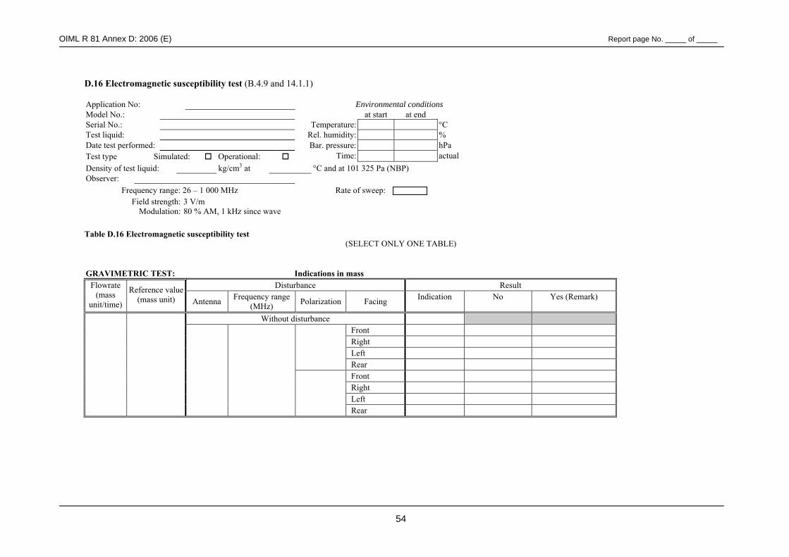
OIML R 81 Annex D: 2006 (E) Report page No. _____ of _____
54
D.16 Electromagnetic susceptibility test (B.4.9 and 14.1.1)
Application No: Environmental conditions Model No.: at start at end Serial No.: Temperature: °C Test liquid: Rel. humidity: % Date test performed: Bar. pressure: hPa Test type Simulated: Operational: Time: actual Density of test liquid: kg/cm3 at °C and at 101 325 Pa (NBP) Observer:
Frequency range: 26 – 1 000 MHz Rate of sweep: Field strength: 3 V/m
Modulation: 80 % AM, 1 kHz since wave
Table D.16 Electromagnetic susceptibility test (SELECT ONLY ONE TABLE)
GRAVIMETRIC TEST: Indications in mass Disturbance Result Flowrate
(mass unit/time)
Reference value (mass unit) Antenna Frequency range
(MHz) Polarization Facing Indication
No Yes (Remark)
Without disturbance Front Right Left
Rear Front Right Left
Rear
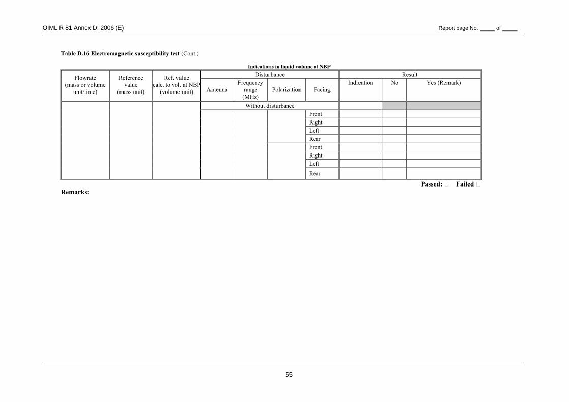
OIML R 81 Annex D: 2006 (E) Report page No. _____ of _____
55
Table D.16 Electromagnetic susceptibility test (Cont.)
Indications in liquid volume at NBP Disturbance Result Flowrate
(mass or volume unit/time)
Reference value
(mass unit)
Ref. value calc. to vol. at NBP
(volume unit) Antenna Frequency
range (MHz)
Polarization Facing Indication
No Yes (Remark)
Without disturbance Front Right Left
Rear Front Right Left
Rear
Passed: Failed Remarks:
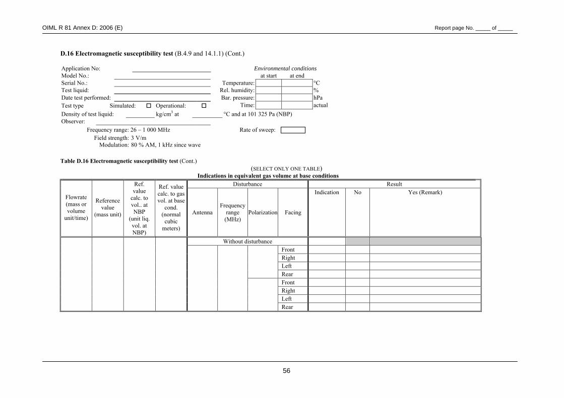
OIML R 81 Annex D: 2006 (E) Report page No. _____ of _____
56
D.16 Electromagnetic susceptibility test (B.4.9 and 14.1.1) (Cont.) Application No: Environmental conditions Model No.: at start at end Serial No.: Temperature: °C Test liquid: Rel. humidity: % Date test performed: Bar. pressure: hPa Test type Simulated: Operational: Time: actual Density of test liquid: kg/cm3 at °C and at 101 325 Pa (NBP) Observer:
Frequency range: 26 – 1 000 MHz Rate of sweep: Field strength: 3 V/m
Modulation: 80 % AM, 1 kHz since wave
Table D.16 Electromagnetic susceptibility test (Cont.) (SELECT ONLY ONE TABLE)
Indications in equivalent gas volume at base conditions Disturbance Result
Flowrate (mass or volume
unit/time)
Reference value
(mass unit)
Ref. value
calc. to vol.. at NBP
(unit liq. vol. at NBP)
Ref. value calc. to gas vol. at base
cond. (normal cubic
meters)
Antenna Frequency
range (MHz)
Polarization Facing
Indication
No Yes (Remark)
Without disturbance Front Right Left
Rear Front Right Left
Rear
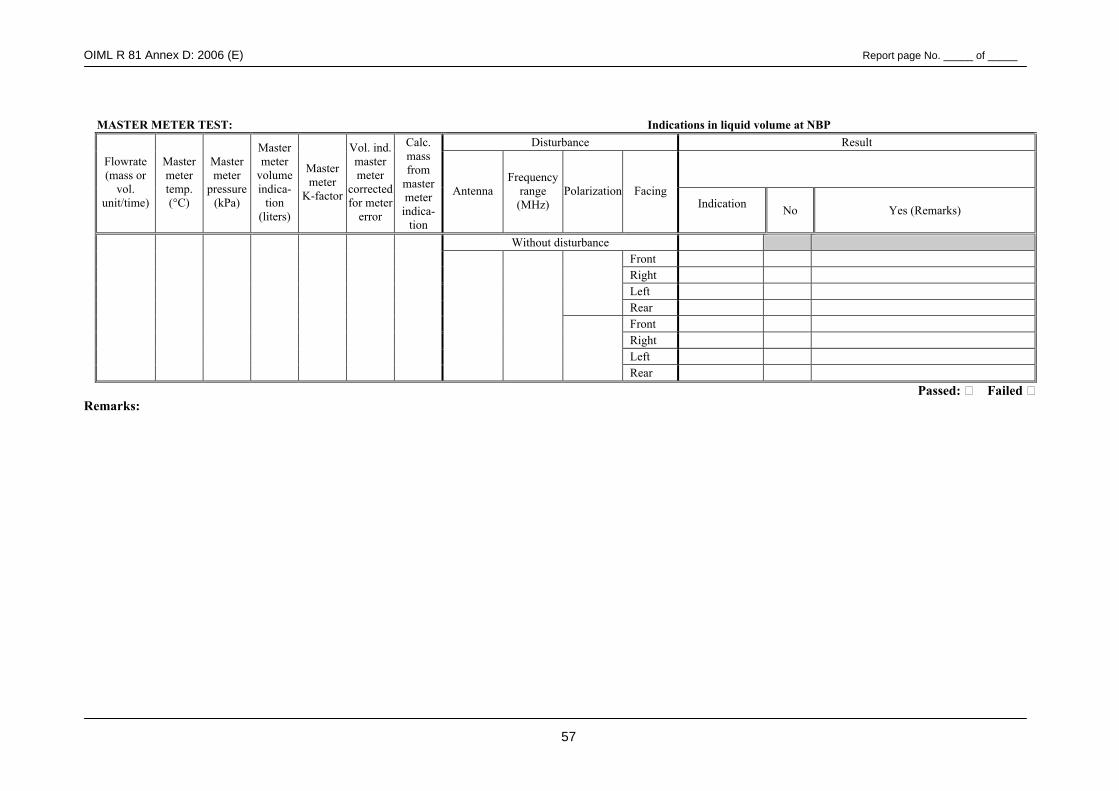
OIML R 81 Annex D: 2006 (E) Report page No. _____ of _____
57
MASTER METER TEST: Indications in liquid volume at NBP
Disturbance Result
Flowrate (mass or
vol. unit/time)
Master meter temp. (°C)
Master meter
pressure (kPa)
Master meter
volume indica-
tion (liters)
Master meter
K-factor
Vol. ind. master meter
corrected for meter
error
Calc. mass from
master meter indica-
tion
Antenna Frequency
range (MHz)
Polarization Facing Indication
No Yes (Remarks)
Without disturbance Front Right Left
Rear Front Right Left
Rear Passed: Failed Remarks:
OIML R 81 Annex D: 2006 (E) Report page No. _____ of _____
58
D.16 Electromagnetic susceptibility test - Test setup (B.4.9 and 14.1.1) (Cont.) Description of the setup, e.g. by photos or sketches
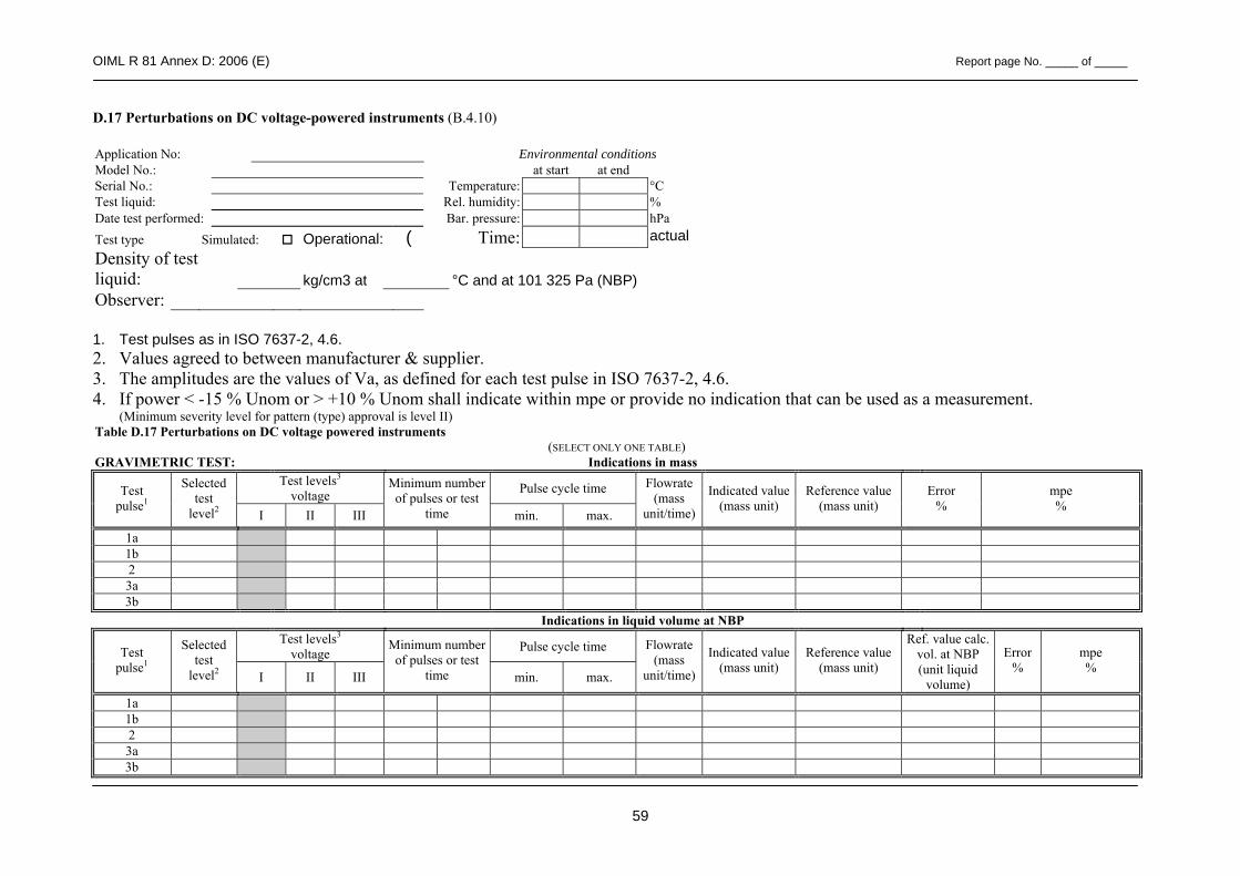
OIML R 81 Annex D: 2006 (E) Report page No. _____ of _____
59
D.17 Perturbations on DC voltage-powered instruments (B.4.10) Application No: Environmental conditions Model No.: at start at end Serial No.: Temperature: °C Test liquid: Rel. humidity: % Date test performed: Bar. pressure: hPa Test type Simulated: Operational: ( Time: actual Density of test liquid: kg/cm3 at °C and at 101 325 Pa (NBP) Observer:
1. Test pulses as in ISO 7637-2, 4.6. 2. Values agreed to between manufacturer & supplier. 3. The amplitudes are the values of Va, as defined for each test pulse in ISO 7637-2, 4.6. 4. If power < -15 % Unom or > +10 % Unom shall indicate within mpe or provide no indication that can be used as a measurement. (Minimum severity level for pattern (type) approval is level II) Table D.17 Perturbations on DC voltage powered instruments
(SELECT ONLY ONE TABLE) GRAVIMETRIC TEST: Indications in mass
Test levels3 voltage Pulse cycle time Test
pulse1
Selected test
level2 I II III
Minimum number of pulses or test
time min. max.
Flowrate (mass
unit/time)
Indicated value(mass unit)
Reference value (mass unit)
Error %
mpe %
1a 1b 2 3a 3b
Indications in liquid volume at NBP Test levels3
voltage Pulse cycle time Test pulse1
Selected test
level2 I II III
Minimum number of pulses or test
time min. max.
Flowrate (mass
unit/time)
Indicated value(mass unit)
Reference value (mass unit)
Ref. value calc. vol. at NBP (unit liquid
volume)
Error %
mpe %
1a 1b 2 3a 3b
OIML R 81 Annex D: 2006 (E) Report page No. _____ of _____
60
Passed: Failed Remarks:
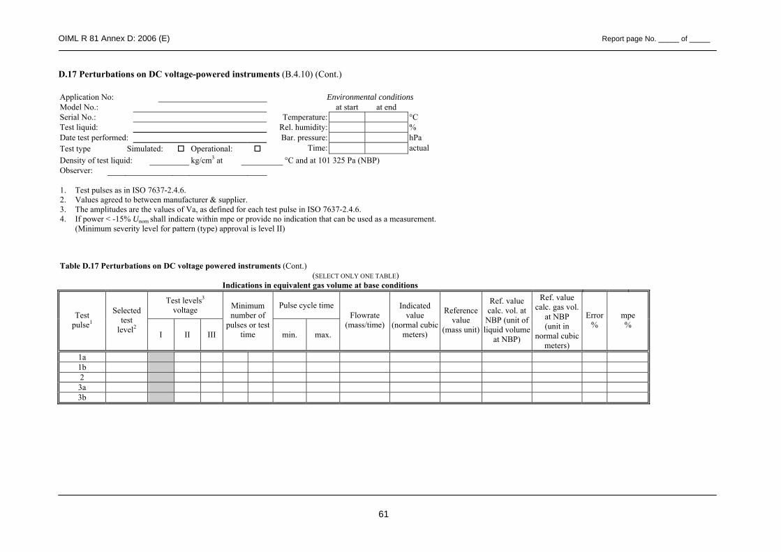
OIML R 81 Annex D: 2006 (E) Report page No. _____ of _____
61
D.17 Perturbations on DC voltage-powered instruments (B.4.10) (Cont.)
Application No: Environmental conditions Model No.: at start at end Serial No.: Temperature: °C Test liquid: Rel. humidity: % Date test performed: Bar. pressure: hPa Test type Simulated: Operational: Time: actual Density of test liquid: kg/cm3 at °C and at 101 325 Pa (NBP) Observer:
1. Test pulses as in ISO 7637-2.4.6. 2. Values agreed to between manufacturer & supplier. 3. The amplitudes are the values of Va, as defined for each test pulse in ISO 7637-2.4.6. 4. If power < -15% Unom shall indicate within mpe or provide no indication that can be used as a measurement.
(Minimum severity level for pattern (type) approval is level II)
Table D.17 Perturbations on DC voltage powered instruments (Cont.) (SELECT ONLY ONE TABLE)
Indications in equivalent gas volume at base conditions
Test levels3 voltage Pulse cycle time
Test pulse1
Selected test
level2 I II III
Minimum number of
pulses or test time min. max.
Flowrate (mass/time)
Indicated value
(normal cubic meters)
Reference value
(mass unit)
Ref. value calc. vol. at
NBP (unit of liquid volume
at NBP)
Ref. value calc. gas vol.
at NBP (unit in
normal cubic meters)
Error%
mpe %
1a 1b 2 3a 3b
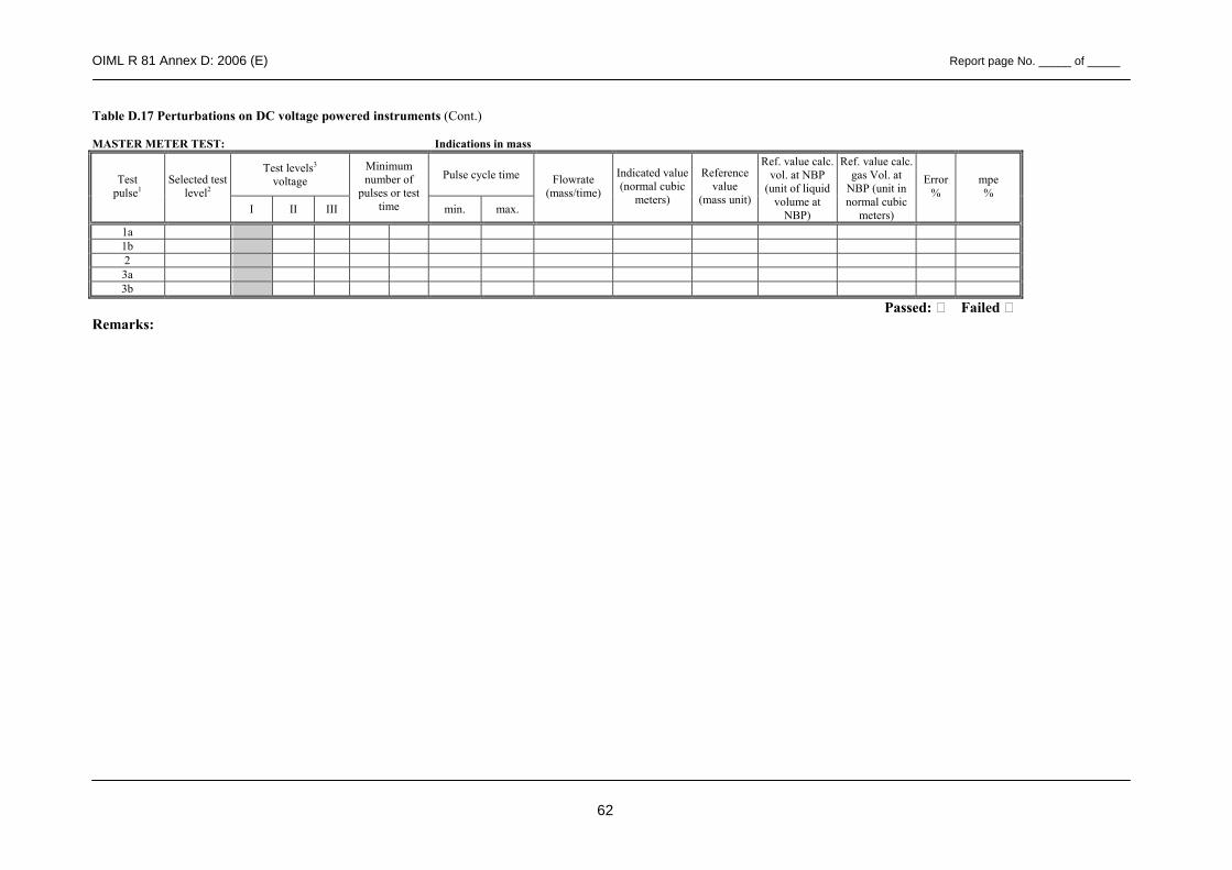
OIML R 81 Annex D: 2006 (E) Report page No. _____ of _____
62
Table D.17 Perturbations on DC voltage powered instruments (Cont.)
MASTER METER TEST: Indications in mass
Test levels3 voltage Pulse cycle time Test
pulse1 Selected test
level2 I II III
Minimum number of
pulses or test time min. max.
Flowrate (mass/time)
Indicated value (normal cubic
meters)
Reference value
(mass unit)
Ref. value calc. vol. at NBP
(unit of liquid volume at
NBP)
Ref. value calc. gas Vol. at
NBP (unit in normal cubic
meters)
Error %
mpe %
1a 1b 2 3a 3b
Passed: Failed Remarks:
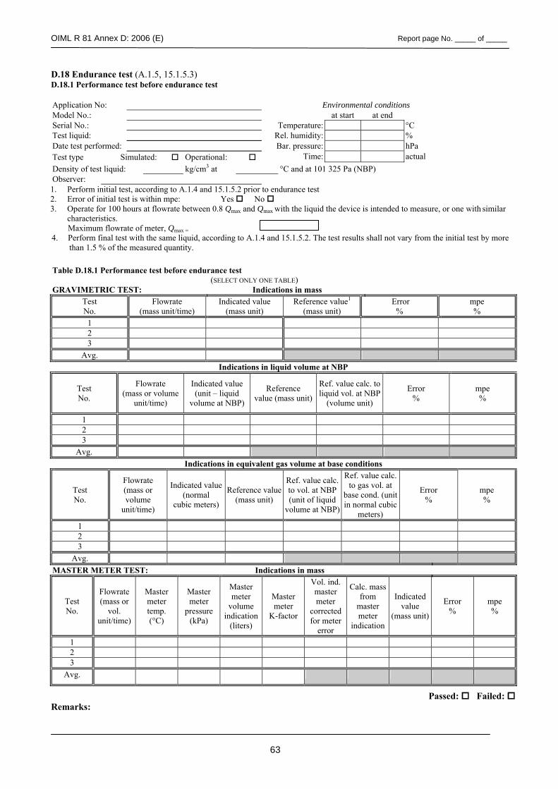
OIML R 81 Annex D: 2006 (E) Report page No. _____ of _____
63
D.18 Endurance test (A.1.5, 15.1.5.3) D.18.1 Performance test before endurance test
Application No: Environmental conditions Model No.: at start at end Serial No.: Temperature: °C Test liquid: Rel. humidity: % Date test performed: Bar. pressure: hPa Test type Simulated: Operational: Time: actual Density of test liquid: kg/cm3 at °C and at 101 325 Pa (NBP) Observer: 1. Perform initial test, according to A.1.4 and 15.1.5.2 prior to endurance test 2. Error of initial test is within mpe: Yes No 3. Operate for 100 hours at flowrate between 0.8 Qmax and Qmax with the liquid the device is intended to measure, or one with similar
characteristics. Maximum flowrate of meter, Qmax = 4. Perform final test with the same liquid, according to A.1.4 and 15.1.5.2. The test results shall not vary from the initial test by more
than 1.5 % of the measured quantity.
Table D.18.1 Performance test before endurance test (SELECT ONLY ONE TABLE)
GRAVIMETRIC TEST: Indications in mass Test No.
Flowrate (mass unit/time)
Indicated value (mass unit)
Reference value1 (mass unit)
Error %
mpe %
1 2 3
Avg. Indications in liquid volume at NBP
Test No.
Flowrate (mass or volume
unit/time)
Indicated value (unit – liquid
volume at NBP)
Reference value (mass unit)
Ref. value calc. to liquid vol. at NBP
(volume unit)
Error %
mpe %
1 2 3
Avg. Indications in equivalent gas volume at base conditions
Test No.
Flowrate (mass or volume
unit/time)
Indicated value (normal
cubic meters)
Reference value (mass unit)
Ref. value calc. to vol. at NBP (unit of liquid
volume at NBP)
Ref. value calc. to gas vol. at
base cond. (unit in normal cubic
meters)
Error %
mpe %
1 2 3
Avg. MASTER METER TEST: Indications in mass
Test No.
Flowrate (mass or
vol. unit/time)
Master meter temp. (°C)
Master meter
pressure (kPa)
Master meter
volume indication
(liters)
Master meter
K-factor
Vol. ind. master meter
corrected for meter
error
Calc. mass from
master meter
indication
Indicated value
(mass unit)
Error %
mpe %
1 2 3
Avg.
Passed: Failed: Remarks:
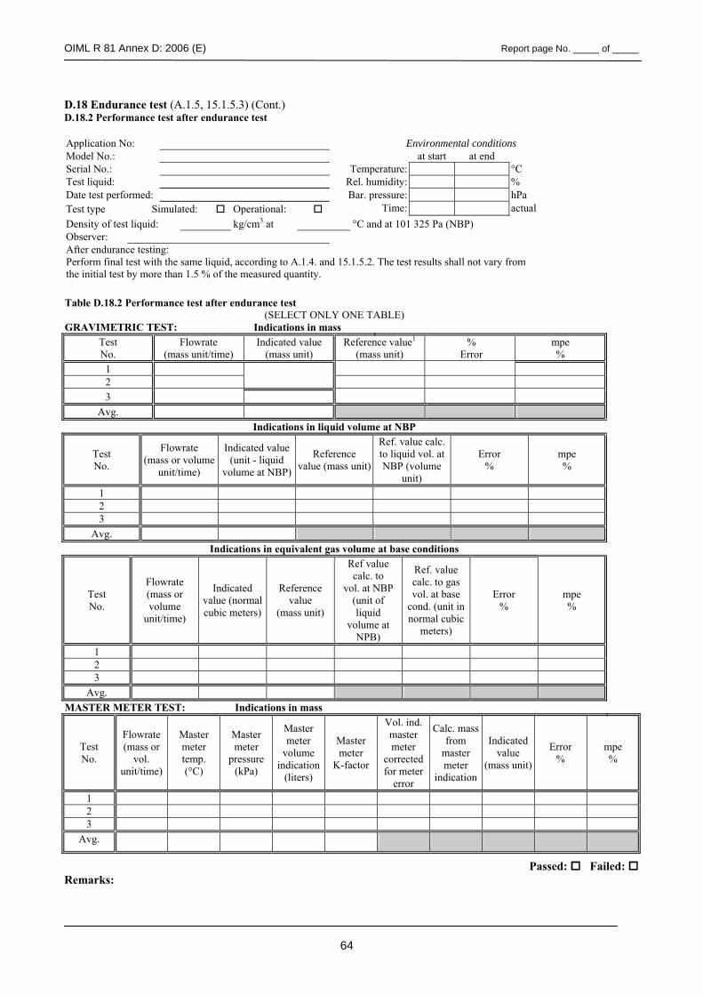
OIML R 81 Annex D: 2006 (E) Report page No. _____ of _____
64
D.18 Endurance test (A.1.5, 15.1.5.3) (Cont.) D.18.2 Performance test after endurance test Application No: Environmental conditions Model No.: at start at end Serial No.: Temperature: °C Test liquid: Rel. humidity: % Date test performed: Bar. pressure: hPa Test type Simulated: Operational: Time: actual Density of test liquid: kg/cm3 at °C and at 101 325 Pa (NBP) Observer: After endurance testing: Perform final test with the same liquid, according to A.1.4. and 15.1.5.2. The test results shall not vary from the initial test by more than 1.5 % of the measured quantity.
Table D.18.2 Performance test after endurance test
(SELECT ONLY ONE TABLE) GRAVIMETRIC TEST: Indications in mass
Test No.
Flowrate (mass unit/time)
Indicated value (mass unit)
Reference value1 (mass unit)
% Error
mpe %
1 2 3
Avg. Indications in liquid volume at NBP
Test No.
Flowrate (mass or volume
unit/time)
Indicated value (unit - liquid
volume at NBP)
Reference value (mass unit)
Ref. value calc. to liquid vol. at NBP (volume
unit)
Error %
mpe %
1 2 3
Avg. Indications in equivalent gas volume at base conditions
Test No.
Flowrate (mass or volume
unit/time)
Indicated value (normal cubic meters)
Reference value
(mass unit)
Ref value calc. to
vol. at NBP (unit of liquid
volume at NPB)
Ref. value calc. to gas vol. at base
cond. (unit in normal cubic
meters)
Error %
mpe %
1 2 3
Avg. MASTER METER TEST: Indications in mass
Test No.
Flowrate (mass or
vol. unit/time)
Master meter temp. (°C)
Master meter
pressure (kPa)
Master meter
volume indication
(liters)
Master meter
K-factor
Vol. ind. master meter
corrected for meter
error
Calc. mass from
master meter
indication
Indicated value
(mass unit)
Error %
mpe %
1 2 3
Avg.
Passed: Failed: Remarks: