Embed Size (px)
Citation preview

2 / 48 wes1404a0600p_08
APPROVALS Reference document number
FM Canada, Certificate No.: FM17CA0074X wes1404a0600s_01
FM US, Certificate No.: FM17US0134X wes1404a0600s_01
BKI ATEX, Certificate No.: BKI13ATEX0017X/3 wes1404m0600p 07
BKI IECEx, Certificate No.: IECEx BKI 13.0005X Issue No.: 2 wes1404a0600p_07
Ex Russia, Certificate No.: RU C-HU.MF62.B.04401 wes1404o0600q_01
INMETRO, Certificate No.: DNV 15.0065 X/1 wes1404p0600p_07
Certificate No.: S7W-WES100

wes1404a0600p_08 3 / 48
BASIC CONCEPT OF MEASUREMENT WITH PiloTREK
Upper dead zone set higherthan the factory default value of P05
DIST = measured distance
LEV = Level (calculated: H - DIST)VOL = Volume (calculated from LEV)
Programmed measuring
range of the applications
Minim
um m
easu
ring d
istan
ce(d
ead z
one)
Lm
in
Facto
ry de
fault v
alue
of P0
5Pr
ogra
mmed
value
of P
04
Maxim
um m
easu
ring r
ange
of th
e ins
trume
nt
Facto
ry de
fault v
alue o
f P04
Maxim
um m
easu
ring d
istan
ce of
the i
nstru
ment
X

4 / 48 wes1404a0600p_08
TABLE OF CONTENTS
1. INTRODUCTION ............................................................................................................................................................................................................................................................. 6 2. ORDER CODES .............................................................................................................................................................................................................................................................. 7 3. TECHNICAL DATA ......................................................................................................................................................................................................................................................... 8
3.1. EXPLOSION PROTECTION, EX MARKINGS, EX LIMIT DATA ........................................................................................................................................................................................... 9 3.1.1. ATEX APPROVAL NO.: BKI13ATEX0017X/2 ....................................................................................................................................................................................................................... 9 3.1.2. IECEX APPROVAL NO.: IECEX BKI 13.0005X ISSUE NO.:1 .................................................................................................................................................................................................. 9 3.1.3. FM US APPROVAL NO.: FM17US0134X ........................................................................................................................................................................................................................... 10 3.1.4. FM CANADA APPROVAL NO.: FM17CA0074X ................................................................................................................................................................................................................. 10 3.1.5. INMETRO APPROVAL NO.:DNV 15.0065 X/1 .................................................................................................................................................................................................................... 11
3.2. DIMENSIONS AND SPECIAL DATA OF THE ANTENNA VARIATIONS .............................................................................................................................................................................. 12 3.2.1. DETERMINE THE MAXIMAL MEASURING RANGE .......................................................................................................................................................................................................................... 18
3.3. ACCESSORIES ....................................................................................................................................................................................................................................................... 19 3.4. CONDITIONS OF SAFE OPERATION ......................................................................................................................................................................................................................... 19 3.5. REPAIR, MAINTENANCE AND STORAGE CONDITIONS ............................................................................................................................................................................................... 19
4. INSTALLATION ............................................................................................................................................................................................................................................................ 20 4.1. MOUNTING ............................................................................................................................................................................................................................................................. 20 4.2. WIRING .................................................................................................................................................................................................................................................................. 22
4.2.1. WIRING OF THE DEVICES ........................................................................................................................................................................................................................................................ 23 4.2.1. DETERMIN THE APPROPRIATE POWER SUPPLY VOLTAGE ............................................................................................................................................................................................................ 24
4.3. LOOP CURRENT CHECKING WITH HAND INSTRUMENT ............................................................................................................................................................................................. 25 5. PROGRAMMING .......................................................................................................................................................................................................................................................... 25
5.1. THE SAP-300 DISPLAY UNIT .................................................................................................................................................................................................................................. 26 5.1.1. PRIMARY MEASUREMENT SCREEN ........................................................................................................................................................................................................................................... 26 5.1.2. INFORMATION SCREENS ......................................................................................................................................................................................................................................................... 28 5.1.3. ECHO MAP ............................................................................................................................................................................................................................................................................ 29
5.2. PROGRAMMING WITH THE SAP-300 DISPLAY MODULE ............................................................................................................................................................................................ 30 5.2.1. COMPONENTS OF THE PROGRAMMING INTERFACE ..................................................................................................................................................................................................................... 30 5.2.2. MENU STRUCTURE ................................................................................................................................................................................................................................................................. 31
5.3. PROGRAMMABLE FEATURES DESCRIPTION ............................................................................................................................................................................................................ 32 5.3.1. BASIC MEASUREMENT SETTINGS.............................................................................................................................................................................................................................................. 32 5.3.2. ANALOGUE OUTPUT ............................................................................................................................................................................................................................................................... 33 5.3.3. DIGITAL OUTPUT .................................................................................................................................................................................................................................................................... 35 5.3.4. MEASUREMENT OPTIMIZATION ................................................................................................................................................................................................................................................. 35 5.3.5. CALCULATIONS ..................................................................................................................................................................................................................................................................... 37 5.3.6. SERVICE FUNCTIONS .............................................................................................................................................................................................................................................................. 40
6. ERROR CODES ............................................................................................................................................................................................................................................................ 42 7. PiloTREK W-100 PARAMETER TABLE ..................................................................................................................................................................................................................... 43 8. MENU MAP ................................................................................................................................................................................................................................................................... 45

wes1404a0600p_08 5 / 48

6 / 48 wes1404a0600p_08
Thank you for choosing a NIVELCO instrument. We are sure that you will be satisfied throughout its use!
1. INTRODUCTION Application
The PiloTREK W-100 non-contact microwave level transmitters provide the most advanced, new generation measurement technique of the industrial process automation field. PiloTREK is an ideal solution of high precision level transmitting of liquids, slurries, dollops, emulsions and other chemicals in a wide range of application area, such as food industry, energy industry, pharmaceutical industry, chemical industry, and even in naval applications with mm accuracy range and high measuring stability. PiloTREK is able to provide an excellent non-contact measurement solution for those substances which tend to steam, or for liquids with a gas layer. Since there is no need for a defined propagation medium in the case of microwaves, the PiloTREK is applicable in vacuum.
Operation principle
The reflection of the emitted microwave impulses is considerably depending on the relative dielectric constant of the measured medium. The essential condition of microwave level measurement is that the relative dielectric constant (εr) of the medium should be more than 1.9.
The operation of the non-contact microwave level transmitters is based on the measurement of the time of flight of the reflected signals, so-called Time Domain Reflectometry (TDR) method.
The propagation speed of microwave impulses is practically the same in air, gases and in vacuum, independently from the process temperature and pressure, so the measured distance is not affected by the physical parameters of medium to be measured.
The PiloTREK level transmitter is a Pulse Burst Radar operating at 25 GHz (K-band) microwave frequency.
The 25 GHz models’ most noticeable advantage over the lower frequency (5 – 12 GHz) radars are the smaller antenna size, the better focusing, lower dead-band and smaller transmission angle.
The level transmitter induces few nanosecond length microwave impulses in the antenna and a part of the energy of the emitted signals reflects back from the measurement surface depending on the measured media. The time of flight of the reflected signal is measured and processed by the electronics, and then this is converted to distance, level or volume proportional data.

wes1404a0600p_08 7 / 48
2. ORDER CODES (NOT ALL COMBINATIONS POSSIBLE!)
PiloTREK W – 1 –
FUNCTION CODE ANTENNA / HOUSING MATERIAL CODE ANTENNA TYPE /
PROCESS CONNECTION CODE PROCESS CONNECTION CODE OUTPUT / EX CODE
2-wire compact E 1.4571 / Aluminium housing S Parabola DN150 / Flange 1 BSP 0 4 – 20 mA + HART 4 2-wire compact + display G 1.4571 / Plastic housing M DN40 Horn / 1½” 4 NPT N 4 – 20 mA + HART /
Ex ia IIIC (ATEX, IECEx) 5 2-wire integrated P PP / Plastic housing P DN50 Horn / 2” 5 DN80 PN25 2 High temperature H 1.4571 / Stainless steel
housing K DN80 Horn / Flange 8 DN100 PN25 3 4 – 20 mA + HART /
Ex ta/tb IIIC (ATEX,IECEx) 6 High temperature transmitter + display J
Planar / 2" (10 m)* A DN125 PN25 4 Planar / 2" (16 m)* B DN150 PN25 5 4 – 20 mA + HART / Ex ia
IIB (ATEX, IECEx) 8 Egg / 1" D DN80, PP 6 Egg / 1½" E DN100, PP 7 4 – 20 mA + HART /XP IS
Div 1 (FM) / ½” NPT A Notes: Egg / 2" F DN125, PP 8 S,M,K: 1.4571 stainless steel horn antenna without housing. DN150, PP 9 4 – 20 mA + HART /
NI Div 2 (FM) / ½” NPT B P: Aluminium horn antenna with antistatic plastic enclosure, only with DN40 and DN50 horn antenna and thread connection. High temperature version only with metal housing! Antenna seal: Viton. Planar antenna only in integrated type!
3" RF 150 psi A
4" RF 150 psi B 4 – 20 mA + HART / Ex db [ia Ga] (ATEX) C
*only for WPP planar antenna type 5" RF 150 psi C 6" RF 150 psi D 3" FF, PP E ACCESSORIES TO BE ORDERED NON-SEPARATELY ORDER CODES 4" RF, PP F PP antenna enclosure with 1½" BSP threaded process connection / Ex type WAP-140-0 / WAP-140-8 5" RF, PP G PP antenna enclosure with 1½" NPT threaded process connection / Ex type WAP-14N-0 / WAP-14N-8 6" RF, PP H PTFE antenna enclosure with 1½" BSP threaded process connection WAT-140-0 JIS 10K80A J PTFE antenna enclosure with 1½" NPT threaded process connection WAT-14N-0 JIS 10K100A K PP antenna enclosure with 2" BSP threaded process connection / Ex type WAP-150-0 / WAP-150-8 JIS 10K125A L PP antenna enclosure with 2" NPT threaded process connection / Ex type WAP-15N-0 / WAP-15N-8 JIS 10K 150A M PTFE antenna enclosure with 2" BSP threaded process connection WAT-150-0 JIS 80A, PP P PTFE antenna enclosure with 2" NPT threaded process connection WAT-15N-0 JIS100A, PP R PTFE antenna enclosure with 2" TriClamp process connection WAT-14T-0 JIS125A, PP S PTFE antenna enclosure with DN50 Pipe coupling process connection WAT-14R-0 JIS 150A, PP T

8 / 48 wes1404a0600p_08
3. TECHNICAL DATA
TYPE PLASTIC HOUSING WM-1-, WP-1-
METAL HOUSING WS-1-, WK-1-
HIGH TEMPERATURE VERSION WH-1-, WJ-1-
Measured media, measured and calculated values Liquids; Level, distance, volume, mass Frequency of the measuring signal ~25 GHz (K-band) Minimal and maximal measuring range*
See chapter 3.2 Material of wetted parts Process connection Beam angle Minimal εr of the medium* Maximal medium pressure (depending on the antenna) 3 bar [43.5 psi] at 25 ºC [77 ºF] 25 bar [362.6 psi] at 120 ºC [248 ºF]
Medium temperature** -30 ºC … +100 ºC [-22 ºF … +212 ºF] (up to max. 2 min.: 120 ºC [77 ºF]), with PP antenna enclosure: 80 ºC [176 ºF] -30 ºC … +180 ºC [-22 … +356 ºF]
Ambient temperature -20 ºC … +60 ºC [-4 ºF …+140 ºF] Resolution 1 mm (0.04 inch)
Typical linearity error (as per MSZ EN 61298-2)* <0.5 m: ±25 mm, 0.5 – 1m: ±15 mm, 1 – 1.5 m: ±10 mm, 1.5 – 8 m: ±3 mm, >8 m: ±0.04% of the measured distance [< 1.6 ft: ±1 inch, 1.6 – 3.3 ft: ±0.6 inch, 3.3 – 4.9 ft: ±0.4 inch, 4.9 – 26 ft: ±0.12 inch, >26 ft: ±0.04% of the measured]
Temperature error (as per MSZ EN 61298-3) 0.05% FSK / 10 °C (-20 … +60 °C [-4 … +140 ºF])
Output Analogue 4 – 20 mA (3.95 – 20.5 mA) Digital communication HART® (minimal terminal resistor: 250 Ohm) Display SAP-300 graphical display unit
Damping time Selectable: 0 – 99 sec Measuring frequency 10 – 60 sec as per the application settings Error indication Output = 22 mA or 3.8 mA (Ex d[ia]: 3.9 mA) Output load Rt = (Ut - 20 V) / 0.022 A, Ut = power supply voltage Power supply voltage 20 V – 36 V DC, Ex ia: 20 V – 30 V DC, Ex d[ia]: 24 V – 36 V DC Electrical protection Class III Ingress protection IP67, integrated type (WPM or WPP): IP68 Electrical connection M20x1.5 cable glands, cable outer diameter: 7 – 13 mm (0.28 in – 0.51 in), cross section: max. 1.5 mm2 (15 AWG) Housing material Paint coated aluminium (EN AC 4200) or plastic (PBT) Sealing Viton®, EPDM Mass 1 – 1.6 kg 2 – 2.6 kg 2.7 – 3.3 kg
*Examined in case of proper application settings at 95% sample rate level. The environment should be free of EMC noises and power supply voltage fluctuations in accordance to the standard, under constant temperature. The reflector should be a plane plate reflector with ideal material, surface and dimensions (min. 3 m x 3 m [10 x 10 ft]). The largest false echo should be 20 dB smaller than the useful echo.
**In case of integrated type transmitters, if the enclosure can be directly in contact with the measured medium, the permissible medium temperature is limited to the ambient temperature.

wes1404a0600p_08 9 / 48
3.1. EXPLOSION PROTECTION, EX MARKINGS, EX LIMIT DATA 3.1.1. ATEX APPROVAL NO.: BKI13ATEX0017X/2
TYPE PLASTIC HOUSING
COMPACT WM-1-
PLASTIC HOUSING INTEGRATED
WPM-1-
METAL HOUSING WS-1- WK-1-
HIGH TEMPERATURE VERSION WITH METAL HOUSING
WH-1-, WJ-1-
Ex marking (ATEX) II 1/2 G Ex ia IIB T6…T5 Ga/Gb II 1 G Ex ia IIB T6…T5 Ga
II 1 G Ex ia IIB T6…T4 Ga II 1 G Ex ia IIB T6…T3 Ga
II 1/2 D Ex ia IIIC T85°C…T110°C Da/Db II 1/2 D Ex ia IIIC T85°C…T180°C Da/Db
II 1/2 D Ex ta/tb IIIC T85°C…T110°C Da/Db II 1/2 D Ex ta/tb IIIC T85°C…T180°C Da/Db
II 1/2 G Ex db [ia Ga] IIB T6…T4 Ga/Gb II 1/2 G Ex db [ia Ga] IIB T6…T3 Ga/Gb
Ex power supply, Intrinsically safety data
Li: 200µH Ci: 16 nF Ui: 30 V Ii: 140 mA Pi: 1 W
Li: 200 µH Ci: 30 nF Ui: 30 V Ii: 140 mA Pi: 1 W
Li: 200 µH Ci: 16 nF Ui: 30 V Ii: 140 m Pi: 1 W „Ex db [ia Ga]”: Ut = 24 – 36 V DC, Um=250 V
Li: 200 µH Ci: 16 nF Ui: 30 V Ii: 140 mA Pi: 1 W „Ex db [ia Ga]”: Ut = 24 – 36 V DC, Um=250 V
3.1.2. IECEX APPROVAL NO.: IECEX BKI 13.0005X ISSUE NO.:1
TYPE PLASTIC HOUSING
COMPACT WM-1-
PLASTIC HOUSING INTEGRATED
WPM-1-
ALUMINIUM HOUSING WS-1- WK-1-
HIGH TEMPERATURE VERSION WITH METAL HOUSING
WH-1-, WJ-1-
Ex marking (IECEx) Ex ia IIB T6…T5 Ga/Gb Ex ia IIB T6…T5 Ga
Ex ia IIB T6…T4 Ga Ex ia IIB T6…T3 Ga
Ex ia IIIC T85°C…T110°C Da/Db Ex ia IIIC T85°C…T180°C Da/Db
Ex ta/tb IIIC T85°C…T110°C Da/Db Ex ta/tb IIIC T85°C…T180°C Da/Db
Ex db [ia Ga] IIB T6…T4 Ga/Gb Ex db [ia Ga] IIB T6…T3 Ga/Gb Ex power supply, Intrinsically safety data
Li: 200 µH Ci: 16 nF Ui: 30 V Ii: 140 mA Pi:1 W
Li: 200 µH Ci: 30 nF Ui: 30 V Ii: 140 mA Pi: 1 W
Li: 200 µH Ci: 16 nF Ui: 30 V Ii: 140 mA Pi: 1 W „Ex db [ia Ga]”: Ut = 24 – 36 V DC, Um=250 V
Li: 200 µH Ci: 16 nF Ui: 30 V Ii: 140 mA Pi: 1 W „Ex db [ia Ga]”: Ut = 24 – 36 V DC, Um=250 V

10 / 48 wes1404a0600p_08
Temperature limit data for ATEX and IECEx approvals:
TEMPERATURE DATA
HAZARDOUS GAS ATMOSPHERES EXPLOSIVE DUST ATMOSPHERES PLASTIC HOUSING METAL HOUSING METAL HOUSING
WM-1- WP-1-
WS-1- WK-1-
HIGH TEMPERATURE WS-1-
WK-1-
HIGH TEMPERATURE
WH-1- WJ-1-
WH-1- WJ-1-
Ex ia IIB Ex ia IIB, Ex db [ia Ga] IIB Ex ia IIIC, Ex ta/tb IIIC Maximum permissible medium temperature +80°C +95°C +80°C +95°C +100°C +130°C +180°C +80°C +95°C +100°C +180°C
Maximum permissible ambient temperature +60°C
Maximum resulting surface temperature +80°C +95°C +80°C +95°C +100°C +130°C +133°C +80°C +95°C +100°C +133°C
Temperature class T6 T5 T6 T5 T4 T4 T3 T85°C T100°C T110°C T180°C
3.1.3. FM US APPROVAL NO.: FM17US0134X (SEE ’SAFETY MANUAL’) The following data is for information purposes only. The FM certificate and the safety instructions can be found in the attached ’Safety Manual’.
TYPE DUAL COMPARTMENT WITH METAL HOUSING
WES-1-A, WGS-1-A
HIGH TEMPERATURE VERSION DUAL COMPARTMENT WITH METAL HOUSING WHS-1-A, WJS-1-A
DUAL COMPARTMENT WITH METAL HOUSING
WES-1-B, WGS-1-B
HIGH TEMPERATURE VERSION DUAL COMPARTMENT WITH METAL HOUSING WHS-1-B, WJS-1-B
Marking (FM US) Class I, Division 1, Group C, D, T6 Ta = -20°C to +60°C, IP67 Class I, Division 2, Group C, D, T6 Ta = -20°C to +60°C, IP67
Maximum power supply 35 V DC
Maximum current 22 mA Maximum Voltage Um: 250 V
3.1.4. FM CANADA APPROVAL NO.: FM17CA0074X (SEE ’SAFETY MANUAL’) The following data is for information purposes only. The FM certificate and the safety instructions can be found in the attached ’Safety Manual’.
TÍPUS DUAL COMPARTMENT WITH METAL HOUSING
WES-1-A, WGS-1-A
HIGH TEMPERATURE VERSION DUAL COMPARTMENT WITH METAL HOUSING WHS-1-A, WJS-1-A
DUAL COMPARTMENT WITH METAL HOUSING
WES-1-B, WGS-1-B
HIGH TEMPERATURE VERSION DUAL COMPARTMENT WITH METAL HOUSING WHS-1-B, WJS-1-B
Marking (FM US) Class I, Division 1, Group C, D, T6 Ta = -20°C to +60°C, IP67 Class I, Division 2, Group C, D, T6 Ta = -20°C to +60°C, IP67
Maximum power supply 35 V DC
Maximum current 22 mA Maximum Voltage Um: 250 V

wes1404a0600p_08 11 / 48
3.1.5. INMETRO APPROVAL NO.:DNV 15.0065 X/1
TYPE PLASTIC HOUSING
COMPACT WM-1-
METAL HOUSING WS-1- WK-1-
HIGH TEMPERATURE VERSION WITH METAL HOUSING WH-1-, WJ-1-
Ex marking (ATEX) Ex ia IIB T6…T5 Ga/Gb
Ex ia IIB T6…T3 Ga Ex ia IIB T6…T3 Ga
Ex ia IIIC T85°C…T110°C Da/Db Ex ia IIIC T85°C…T180°C Da/Db
Ex ta IIIC T85°C…T110°C Da/Db Ex ta IIIC T85°C…T180°C Da/Db
Ex power supply, Intrinsically safety data
Li: 200 µH Ci: 16 nF Ui: 30 V Ii: 140 mA Pi: 1 W
Li: 200 µH Ci: 16 nF Ui: 30 V Ii: 140 mA Pi: 1 W Li: 200 µH Ci: 16 nF Ui: 30 V Ii: 140 mA Pi: 1 W
Not all types can be ordered with INMETRO approval.
Temperature limit data for INMETRO approval:
TEMPERATURE DATA
HAZARDOUS GAS ATMOSPHERES EXPLOSIVE DUST ATMOSPHERES PLASTIC HOUSING METAL HOUSING METAL HOUSING
WM-1- WP-1-
WS-1- WK-1-
HIGH TEMPERATURE WS-1-
WK-1-
HIGH TEMPERATURE
WH-1- WJ-1-
WH-1- WJ-1-
Ex ia IIB Ex ia IIIC, Ex ta IIIC
Maximum permissible medium temperature +80°C +80°C +80°C +90°C +100°C +180°C +80°C +90°C +100°C +180°C
Maximum permissible ambient temperature +60°C
Maximum resulting surface temperature +75°C +80°C +75°C +90°C +100°C +175°C +75°C +90°C +100°C +175°C
Temperature class T6 T5 T6 T5 T4 T3 T85°C T100°C T110°C T180°C

12 / 48 wes1404a0600p_08
3.2. DIMENSIONS AND SPECIAL DATA OF THE ANTENNA VARIATIONS
ALUMINIUM HOUSING, 1½" HORN ANTENNA
WES-140-, WGS-140-, WES-14N-, WGS-14N-
ALUMINIUM HOUSING, 2" HORN ANTENNA
WES-150-, WGS-150- WES-15N-, WES-15N-
PLASTIC HOUSING, 1½" HORN ANTENNA
WEM-140-, WGM-140-, WEM-14N-, WGM-14N-
PLASTIC HOUSING, 2" HORN ANTENNA
WEM-150-, WGM-150- WEM-15N-, WGM15N-
139
141
2
20
Ø38
BSP 1 1/2"
NPT 1/2" (2x)M20 x 1.5(2x)
133
Sw.55
LMIN
M6/Sw.3
139
141NPT 1/2" (2x)
M20 x 1.5(2x)
Sw.65M6/Sw.3
168
Ø48 LMIN20
2
BSP 2"
2
20
Ø38
BSP 1 1/2"
133
Sw.55
LMIN
M6/Sw.3
135
2 x NPT 1/2"
M20 x 1,5 (2x)
137
135
NPT 1/2" (2x)
M20 x 1,5 (2x)
137
M6/Sw.3
168
Ø48 LMIN
20
2
BSP 2"
Sw.65
Material of wetted parts 1.4571, PTFE, FPM Process connection 1½" BSP, 1½" NPT 2" BSP, 2" NPT 1½" BSP, 1½" NPT 2" BSP, 2" NPT Beam angle (-3 dB) 19° 16° 19° 16° Minimal measuring distance* 200 (7.9 inch)
* Under reference conditions described in the 3rd chapter. LMIN is according to the drawings

wes1404a0600p_08 13 / 48
ALUMINIUM HOUSING, 1½" ANTENNA WITH PLASTIC ENCLOSURE
WES-140-, WGS-140- + WAP-140-0, WAP-14N-0
PLASTIC HOUSING, 1½" PP ENCAPSULATED ANTENNA
WEP-140-, WGP-140- WEP-14N-, WGP-14N-
ALUMINIUM HOUSING, 2" ANTENNA WITH PLASTIC ENCLOSURE
WES-150-, WGS-150- + WAP-150-0, WAP-15N-0
PLASTIC HOUSING, 2" PP ENCAPSULATED PLASTIC ANTENNA
WEP-150-, WGP-150- WEP-15N-, WGP-15N-
139
139NPT 1/2" (2x)
M20 x 1.5 (2x)
M6/Sw.3
153
Sw.5522
100
Ø44 LMIN
BSP 1 1/2"NPT 1 1/2"
Sw.55
135
NPT 1/2" (2x)
M20 x 1,5 (2x)
172
22
100
118
Ø42 LMIN
BSP 1 1/2"NPT 1 1/2"
Sw.55
139
139NPT 1/2" (2x)
M20 x 1.5 (2x)
M6/Sw.3
194
24
122
Ø54,5
BSP 2"NPT 2"
Sw.65
Sw.65
LMIN
135
NPT 1/2" (2x)
M20 x 1,5 (2x)
186
24
145
BSP 2"NPT 2"
Sw.65
122
Ø54,5 LMIN
Material of wetted parts PP + EPDM Process connection 1½" BSP, 1½" NPT 2" BSP, 2" NPT
Beam angle (-3 dB) 19° 16° Minimal measuring distance* 300 mm (11.8 inch)
* Under reference conditions described in the 3rd chapter. LMIN is according to the drawings

14 / 48 wes1404a0600p_08
INTEGRATED PLASTIC HOUSING, 1½" HORN ANTENNA
WPM-140-, WPM-14N-
INTEGRATED PLASTIC HOUSING, 2" HORN ANTENNA
WPM-150-, WPM-15N-
INTEGRATED PLASTIC HOUSING, 1½" PP ENCAPSULATED ANTENNA
WPP-140-, WPP-14N-
INTEGRATED PLASTIC HOUSING, 2" PP ENCAPSULATED ANTENNA
WPP-150-, WPP-15N-
Material of wetted parts 1.4571, PTFE, PP, FPM 1.4571, PTFE, PP, FPM PP + EPDM PP + EPDM Process connection 1½" BSP, 1½" NPT 2" BSP, 2" NPT 1½" BSP, 1½" NPT 2" BSP, 2" NPT Beam angle (-3 dB) 19° 16° 19° 16° Minimal measuring distance* 200 mm (7.9 inch) 300 mm (11.8 inch)
* Under reference conditions described in the 3rd chapter. LMIN is according to the drawings
wes1404a0600p_08 15 / 48
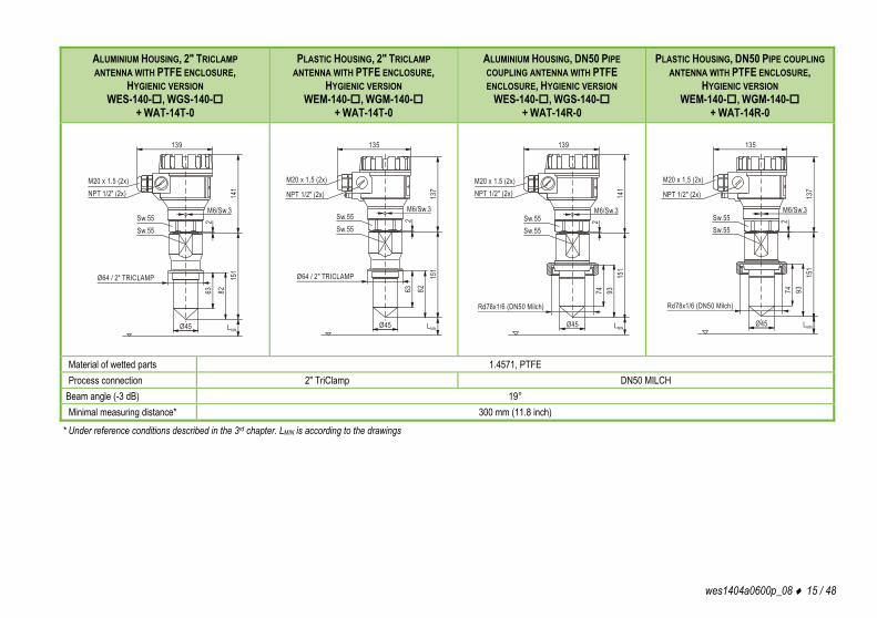
ALUMINIUM HOUSING, 2" TRICLAMP ANTENNA WITH PTFE ENCLOSURE,
HYGIENIC VERSION WES-140-, WGS-140-
+ WAT-14T-0
PLASTIC HOUSING, 2" TRICLAMP ANTENNA WITH PTFE ENCLOSURE,
HYGIENIC VERSION WEM-140-, WGM-140-
+ WAT-14T-0
ALUMINIUM HOUSING, DN50 PIPE COUPLING ANTENNA WITH PTFE ENCLOSURE, HYGIENIC VERSION
WES-140-, WGS-140- + WAT-14R-0
PLASTIC HOUSING, DN50 PIPE COUPLING ANTENNA WITH PTFE ENCLOSURE,
HYGIENIC VERSION WEM-140-, WGM-140-
+ WAT-14R-0
139
141NPT 1/2" (2x)
M20 x 1.5 (2x)
M6/Sw.32
151
63 82
Ø45 LMIN
Sw.55
Ø64 / 2 " TRICLAMP
Sw.55
M6/Sw.3
2
151
63 82
Ø45 LMIN
Sw.55
Ø64 / 2 " TRICLAMP
Sw.55
135
NPT 1/2" (2x)
M20 x 1,5 (2x)
137
139
141NPT 1/2" (2x)
M20 x 1.5 (2x)
M6/Sw.3
2
151
74 93
Ø45 LMIN
Sw.55
Rd78x1/6 (DN50 Milch)
Sw.55
135
NPT 1/2" (2x)
M20 x 1,5 (2x)
137
M6/Sw.3
2
151
74 93
Ø45 LMIN
Sw.55
Rd78x1/6 (DN50 Milch)
Sw.55
Material of wetted parts 1.4571, PTFE Process connection 2" TriClamp DN50 MILCH
Beam angle (-3 dB) 19° Minimal measuring distance* 300 mm (11.8 inch)
* Under reference conditions described in the 3rd chapter. LMIN is according to the drawings

16 / 48 wes1404a0600p_08
ALUMINIUM HOUSING, HORN ANTENNA WITH FLANGE WES-18-, WGS-18-
ALUMINIUM OR PLASTIC HOUSING, PARABOLIC ANTENNA WITH FLANGE WE-11-, WG-11-
INTEGRATED PLASTIC HOUSING, PLANAR ANTENNA
WPP-1A- WPP-1B-
FLAMEPROOF, ALUMINIUM DUAL CHAMBER HOUSING, 1½" HORN ANTENNA
WES-140-C, WGS-140-C WES-14N-C, WGS-14N-C
139
165NPT 1/2" (2x)
M20 x 1.5 (2x)
M6/Sw.32Sw.55
240
DN80 PN25DN100 PN 25DN125 PN25DN150 PN25
3" RF 150psi4" RF 150psi5" RF 150psi6" RF 150psi
JIS 10K80AJIS 10K100AJIS 10K125AJIS 10K150A
Ø75 LMIN
139 ~ " ( 5.5 )
141
~6"
(5.
)
Ø148 [ 5.83"]~
NPT 1/2" (2x)M20 x 1.5 (2x)
Sw.55
85 ~
2"(5
.)
DN150 PN25 / 6 " RF 150 psi / JIS 10K150A L MIN
M6 Sw.3/
1" BS P
2216
Ø96
227
802 BS P" 2" NPT
L MIN
103
Sw.55
18
133
Ø38
BSP 1 1/2"
172
M6/Sw.3
L MIN
Ø103
Material of wetted parts 1.4571, PTFE, FPM 1.4571, PTFE, Zn PP + EPDM 1.4571, PTFE, FPM Process connection Flange 2" BSP, 2" NPT 1½" BSP, 1½" NPT Beam angle (-3 dB) 11° 6° 16° 19° Minimal measuring distance* 200 mm (7.9 inch) 430 mm (16.9 inch) 300 mm (11.8 inch) 200 mm (7.9 inch)
* Under reference conditions described in the 3rd chapter. LMIN is according to the drawings

wes1404a0600p_08 17 / 48
HIGH TEMPERATURE VERSION, ALUMINIUM HOUSING, 1½" HORN ANTENNA
WHS-140-, WJS-140-, WHS-14N-, WJS-14N-
HIGH TEMPERATURE VERSION, ALUMINIUM HOUSING,
2" HORN ANTENNA WHS-150-, WJS-150-, WHS-15N-, WJS-15N-
HIGH TEMPERATURE VERSION, ALUMINIUM HOUSING,
HORN ANTENNA WITH FLANGE WHS-18-, WJS-18-
HIGH TEMPERATURE VERSION, ALUMINIUM HOUSING, 2" TRICLAMP ANTENNA WITH PTFE ENCLOSURE,
HYGIENIC VERSION WHS-140-, WJS-140-
+ WAT-14T-0
139
226
NPT 1/2" (2x)M20 x 1.5 (2x)
20
Ø38
BSP 1 1/2"NPT 1 1/2"
133
LMIN
2
M6/Sw.3Sw.55
Ø100
139
226
NPT 1/2" (2x)M20 x 1.5 (2x)
Ø100
168
Ø48 LMIN
20
2
BSP 2"NPT 2"
Sw.60 M6/Sw.3
139
NPT 1/2" (2x)M20 x 1.5 (2x)
2
M6/Sw.3Sw.55
Ø100
Ø75
DN80 PN25DN100 PN 25DN125 PN25DN150 PN25
3" RF 150psi4" RF 150psi5" RF 150psi6" RF 150psi
JIS 10K80AJIS 10K100AJIS 10K125AJIS 10K150A
250
LMIN
240
139
226
NPT 1/2" (2x)M20 x 1.5 (2x)
2
M6/Sw.3Sw.55
Ø100
151
63 82
Ø45 LMIN
Ø64 / 2 " TRICLAMP
Sw.55
Ø47,3
Material of wetted parts 1.4571, PTFE, FPM PTFE Process connection 1½" BSP, 1½" NPT 2" BSP, 2" NPT Flange 2" TriClamp Beam angle (-3 dB) 19° 16° 11° 19° Minimal measuring distance* 200 mm (7.9 inch) 300 mm (11.8 inch)
* Under reference conditions described in the 3rd chapter. LMIN is according to the drawings

18 / 48 wes1404a0600p_08
3.2.1. DETERMINE THE MAXIMAL MEASURING RANGE The maximal possible measuring distance of device types: The maximal measuring range of the PiloTREK radars is significantly depending
on the circumstances of the application environment and on the selected device type. Depending on the relative dielectric constant of the measuring medium and the process conditions the maximal measurement range (achievable under the reference conditions) may decrease by even 85% (reduce about to one-sixth!). In case of planar antenna version, the maximum measuring distance depending on the dielectric characteristic of the medium to be measured is the same as the encapsulated DN40 horn antenna version.
Type Antenna type Measuring distance
WPP-1A Planar antenna 10000 mm (32.8 ft) WPP-1B 16000 mm (52.5 ft)
W-14 DN40 (1½") horn antenna with enclosure DN40 (1½") horn antenna without enclosure 18000 mm (59 ft)
W-15 TDN50 (2") horn antenna with enclosure 20000 mm (65.6 ft) DN50 (2") horn antenna without enclosure
23000 mm (75.5 ft) W-18 DN80 horn antenna with enclosure W-11 DN150 horn antenna without enclosure
The maximal measuring distance is illustrated in the diagram on the right in case of materials with different relative dielectric constant. The diagram is valid for horn antenna without plastic enclosure, for liquids with still surface not tending to foaming, vapouring or steaming and in case of ideally slow (<5 m/h [<16.4 ft/hr]) rate of level change.
2,5 3,2 8 50
5 m
10 m
15 m
Max. measuring range
18 m20 m
23 m
2 4 5 6,3 10 12 16 20 25 32 40 63 80 100 125
25 m
r1,61,4 1,8
DN150: Stainless steel parabolic antennaDN80: horn antenna (W S-18 - )DN50: (W S-15 - )DN40: (W S-14 - ) K M
Stainless steelStainless steel horn antennaStainless steel horn antenna
DN50
DN40
DN 08
DN 015
Depending on the process conditions or the plastic antenna enclosure the following typical reducing factors are recommended to be considered in order to calculate the maximal measuring range. When more than one reducing factors occur at the same time then all the factors should be considered for the calculation:
Process Condition Reflection reduction in Amplitude Maximum measuring distance decrease by Reducing Factor Slow mixing or slightly waving 2 – 6 dB 20 – 50% 0.8 – 0.5 Foaming Fast mixing, vortex 8 – 10 dB 60 – 70% (the measurement might be completely terminated) 0.4 – 0.3 Steaming, condensation 3 – 10 dB 30 – 70% (the measurement might be completely terminated) 0.7 – 0.3 PP antenna enclosure 2 dB 20% 0.8 PTFE antenna enclosure 1 dB 10% 0.9
For example: Measurement medium is Styrene (εr = 2.4) at 25 ºC (77 ºF) process temperature and slowly mixed. The device type is WGS-150-4 with WAT-150-0 antenna enclosure. The maximal measuring range is (9 m [29.5 ft] * 0.5 * 0.9) = 4 m (13 ft).

wes1404a0600p_08 19 / 48
3.3. ACCESSORIES User’s and Programming Manual Warrant Card EU declaration of Conformity 2 pcs. M20x1.5 cable glands Sealing (Klinger® Oilit) only for BSP threaded process connection 3.4. CONDITIONS OF SAFE OPERATION To avoid the danger of electrostatic charge accumulation, in case of the WP, WM types (with plastic electronic housing, plastic antenna enclosure or PP flange) the following safety rule shall be observed: The measured medium should be an electrostatic conductor, and the electrical resistivity of the measured medium cannot exceed 104 . The speed and the method of the filling and emptying process should be chosen properly according to the measured medium. The material of the plastic antenna enclosures can produce static electricity. The antenna enclosure is allowed to clean only with wet rag. The wiring chamber cover of the Ex d [ia] dual compartment flameproof housing may not be opened while the electrical circuits are energized or if
explosive atmosphere is present. If the WS with aluminium housing is installed into a location which requires ‘Ga’ protection level, the units should be mounted that they are protected against rare occurring impacts and friction effects which may be source of a potential ignition. Meeting the requirements of the technological process Please carefully consider that all parts of the instrument which possible to come into contact with the measured medium – including the transducer, the sealing and any other mechanical parts – should meet all requirements of the applied technological process, such as the process pressure, temperature and chemical effects of the used technologies. In addition, it is necessary to take into account at devices with PP flange that the PP flange’s mechanical strength is much smaller than the same sized metal flange’s. FCC Radio license This device complies with Part 15 of the FCC Rules. Operation is subject to the following two conditions: (1) This device may not cause harmful interference, and (2) this device must accept any interference received, including interference that may cause undesired operation. Changes or modifications not expressly approved by the manufacturer could void the user’s authority to operate the equipment.
3.5. REPAIR, MAINTENANCE AND STORAGE CONDITIONS PiloTREK units do not require maintenance on a regular basis. Repair during or after the guarantee period should only be carried out by NIVELCO. Devices for repair should be returned fully cleaned, and disinfected. Unused devices must be stored within the ambient temperature range specified in the technical data, and a maximum of 98% relative humidity.

20 / 48 wes1404a0600p_08
4. INSTALLATION
4.1. MOUNTING When choosing the installation place please ensure proper space for later calibrations, verification or maintenance service. PLACEMENT The ideal position for the PiloTREK is on ther = (0.3 – 0.5) R (in case of cylindrical tank). It is highly recommended to consider the beam cone on the 2nd page drawing. The distance between the sensor and the tank wall should be at least 200 mm (7.9 inch). If the unit is installed into dome top or spherical tank, unwanted multiple reflections may appear, which can cancel each other and the measuring signal out, this way it can interfere the measurement.
rR
MOVING LIQUID SURFACE Waving, vortex or strong vibration effects can have negative influence on the measurement accuracy and the maximal measuring range. To avoid these effects, the mounting placement should be as far as possible from the sources of these disturbing effects. According to measurement experiences the maximal measuring distance may decrease by 50 – 70% when the liquid surface is vortexing (see chapter 3.2). For this reason, the device should be mounted as far as possible from the filling stream or the tank outlet.
FOAMING Filling, stirring or any other processes in the tank can generate dense foams on the liquid surface, which may considerably damp the reflected signals. According to measurement experiences, in these cases the maximal measuring distance decreases at least approximately by 50%.
FUMES, VAPOURS If the measured medium or its foam can reach the antenna or the measured medium is highly fuming, these cases build-ups can form on the sensor, which may result unreliable level measurement.

wes1404a0600p_08 21 / 48
SENSOR ALIGNMENT The antenna face should be parallel to the medium surface within 2° – 3°.
TEMPERATURE To avoid overheating the instrument should be protected against direct sunshine.
Roof sunshade
OBSTACLES Prior to the installation make sure that no objects (cooling pipes, bracing elements, thermometers, etc.) cross the microwave signals. Especially in case of extraordinary large silos bracing elements and other structural obstacles may cause false reflections which can be damped in most cases: a small bent metal deflector plate mounted above the obstacle can disperse the microwave signals and eliminates the false reflections which disturb the reliable measurement. If there is no possible mechanical solution to avoid these kinds of false reflections, the programming of the instrument allows blocking out the obstacles. (see: 5.3.4.5)
POLARIZATION PLANE The emitted radar impulses of PiloTREK are electromagnetic waves. The orientation of the polarization plane is the same as for the electric wave component of the electro-magnetic wave. The rotation of the polarization plane compared to the tank position could be useful (for example to avoid disturbing reflections) in certain applications. To rotate the polarization plane loosen the M6 hex socket set screw above the process connection and rotate the instrument. Then tighten the unit by the screw.
M6/Sw.3
EMPTY TANK Especially in case of standing tanks with hemispherical bottom and in case of tanks which have any equipment inside at the bottom (e.g. heating element, stirrer) wrong level measurement may happen when the tank is totally emptied. The reason for this measurement error is that the tank bottom or the objects at the bottom disperse or reflect the emitted microwave signals. Furthermore, the lower signal-level dispersed radar impulses may interfere with itself inside the tank. In order to perform reliable level measurement there should be at least 100 mm (4 inch) liquid level above the disturbing objects at the bottom or above the hemispherical tank bottom.
SOCKET, NOZZLE The process connection should be implemented that the antenna end should protrude at least 10 mm (0.4 inch) out of the socket.
>10mm
>10mm

22 / 48 wes1404a0600p_08
4.2. WIRING The instrument operates from 20 – 36 V galvanic isolated and not grounded DC power supply in two-wire system. (For Ex version: 20 – 30 V DC!) The voltage value measured on the terminal of the instrument should be minimum 20 V (in case of 4 mA)! In case of using HART® interface – to achieve proper communication between the transmitter’s interface and the power-supply – a minimal 250 Ohm resistance should be maintained within the network. The instrument should be wired with shielded cable led through the cable gland. The wiring of the cables can be done after removing the cover of the instrument and the SAP display unit. IMPORTANT: The grounding screw on the housing of the transmitter should be connected to the equipotential network. Resistance of the EP network should be R 2 Ohm measured from the neutral point. Shielding of the cable should be grounded at the control room side to the EP network. To avoid disturbing noises, keep away of closeness to high-voltage cables. Especially the inductive couplings of AC harmonics can be critical (which are present at frequency converter control) because even cable shielding does not supply effective protection against these cases.
2 3 4 5 61
1/2” NPT
Display unitconnector
Loop currentmeasuring connector
4...20 mA (HART)
loop currentand supply
GND
1/2” NPT
M20x1,5M20x1,5
3 42 5U - +
The instrument may be damaged by electrostatic discharge (ESD) via its terminal, thus apply the precautions commonly used to avoid electrostatic discharge e.g. by touching a properly grounded point before removing the cover of the enclosure. A possible electrostatic discharge can cause damage for the instrument. Do not touch the internal terminals!
WATER / VAPOUR To achieve suitable ingress protection NIVELCO recommends using the suggested cable outer diameter (see technical data table in the 3rd chapter) and fasten properly the cable gland. NIVELCO also recommends leading the connecting cables downwards to lead aside the rain water and the condensed water. This is needed in case of outside installations and some special applications where there is very high humidity or the possibility of water condensation is quite high (for example in cleaning, purification processes, in cooled and / or heated tanks).
wes1404a0600p_08 23 / 48
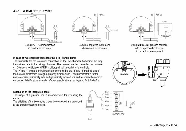
4.2.1. WIRING OF THE DEVICES V 200mV
A
24V
250 OhmHART
Ex power supply
Ex Non Ex
MultiCONT
Ex Non Ex
Using HART® communication
in non-Ex environment Using Ex approved instrument
in hazardous environment Using MultiCONT process controller
with Ex approved instrument in hazardous environment
In case of two-chamber flameproof Ex d [ia] transmitters: The terminals for the electrical connection of the two-chamber flameproof housing transmitters are in the wiring chamber. The device can be connected to two-wire 4 – 20 mA current loop or HART® multidrop circuit through these terminals. The “+” and “-” wiring terminal points are connected to the “3” and “4” marked pins of the device's electronics through a properly dimensioned – and uncorrectable for the user – certified intrinsically safe and galvanically isolated unit and a certified flameproof conductor. Additional intrinsically safe barriers/circuitry is not required for this device.
Extension of the integrated cable: The usage of a junction box is recommended for extending the cable. The shielding of the two cables should be connected and grounded at the signal processing device. Yellow
GreenYellow
Brown
White
Green
JUNCTION BOX

24 / 48 wes1404a0600p_08
In case of integrated version: Prior to wiring ensure that the power supply is turned off at the source. (For wiring the unit 6 x 0.5 mm2 cross section or greater cable is recommended). The necessary programming can be made after energizing the unit.
PowersupplyPower supply
+HART+Current output HART modem
Ibrownwhite
green
green/yellow
R
yellowTRAN
SMIT
TER
mA
V200mV
Colour codes of the wires: Green – (+) Positive point of current loop measurement Yellow – (-) Negative point of current loop measurement White – I (-) Negative point of current loop, power supply and HART® Brown – I (+) Positive point of current loop, power supply and HART® Green/Yellow – GND Grounding and shielding point
4.2.1. DETERMIN THE APPROPRIATE POWER SUPPLY VOLTAGE The minimal power supply voltage required by the PiloTREK devices is depending on the load impedance in accordance to the below diagram: 22
2120191817
1615141312
2 4 6 8 10 12 14 16 18 20 22
19,1
13,6
B
A Minimal supply voltage on the input terminalsof the device
Minimal supply voltage (considering the voltage drop on the 250 Ohm loop resistor)
A: minimal supply voltage on the input terminals of the device B: minimal supply voltage (considering the voltage drop on the 250 Ohm loop resistor) Calculation example: Voltage drop calculated with 22 mA: U minimal supply voltage (22 mA) = 22 mA x load resistance+ U input minimum (22 mA) U minimal supply voltage (22 mA) = 22 mA x 250 Ohm + 13.6 V = 5.5 V + 13.6 V = 19.1 V
In order to provide operation in the total current loop range the calculation should be also checked with 4 mA: U minimal supply voltage (4 mA) = 4 mA x load resistance + U input minimum (4 mA)
U minimal supply voltage (4 mA) = 4 mA x 250 Ohm + 19 V = 1 V + 19 V = 20 V Therefore in case of 250 Ohm load resistance 20 V power supply voltage is just enough for the total 4 – 20 mA measuring range.

wes1404a0600p_08 25 / 48
4.3. LOOP CURRENT CHECKING WITH HAND INSTRUMENT After removing the cover and the Display Module, the actual loop current can be measured throughout an internal 1 Ohm shunt resistor by connecting a voltmeter (in the range of 200 mV) to the points 2 and 5 indicated on the wiring drawing above (see 4.2.1).
5. PROGRAMMING The PiloTREK transmitters can be programmed (basically) with the following two ways: Programming with the SAP-300 display unit (see 5.2)
All features of the unit can be accessed and all parameters can be set, such as measurement configuration and optimisation, outputs, dimensions for 11 tanks with different shape, 99-point linearization.
Programming with MultiCONT process controller or EView2 PC configuration software The PiloTREK WG and WJ types include the SAP-300 display unit. The PiloTREK transmitters are fully operational without the SAP-300 display as well, it is only needed for local programming and / or local measurement displaying. FACTORY DEFAULT SETTING The PiloTREK W-100 series level transmitters are factory programmed by the following way:
Measurement mode: Level (LEV). The displayed value is the measured level. The current output and the bargraph on the right are proportional to the measured level. 4 mA and 0% are assigned to zero level. 20 mA and 100% are assigned to the maximal level. Error indication by the current output: holding the last value. Level tracking time constant: 15 sec.
The instrument regards the distance (DIST) measured from the antenna end as the basic measurement value. This distance is handled and display in one of the selected dimensions: m, cm, mm, feet, or inch. Since the maximal measurement distance is given (entered in P04) the instrument can calculate the actual level (LEV) value. If the proper mechanical dimensions of the mounting – distance between the sealing and the tank bottom – is known, the measured level values can be more accurate by adding this data. The level values calculated that way are the base for volume (VOL) calculation and the 99-point linearization table (VMT) also uses these values as input data.

26 / 48 wes1404a0600p_08
5.1. THE SAP-300 DISPLAY UNIT 5.1.1. PRIMARY MEASUREMENT SCREEN The SAP-300 is a 64 x 128 dot-matrix LCD display which can be plugged into the transmitter. (It is universal – usable in other NIVELCO devices as well – provided that the system software supports SAP-300.)
Warning! The SAP-300 module is based on LCD technology, so please make sure it is not exposed to permanent heat or direct sunlight, in order to avoid damage of the display unit. If the instrument cannot be protected against direct sunlight or high temperature that is beyond the standard operating temperature range of the SAP-300, please do not leave the SAP display in the instrument.
Measurement displaying with the SAP-300 display unit Elements of the displaying:
1. Primary (Measured) Value (PV), in accordance to BASIC SETUP / PV. MODE. 2. Calculation mode of Primary Value (PV), in accordance to BASIC SETUP / PV. MODE. 3. Type and value of the initial quantity used for calculating the Primary Value (PV): - in case of Level measurement (LEV) it is Distance (DIST), - in case of Volume measurement (VOL) it is Level (LEV). 4. Trend direction arrows. The empty triangle shows when the change of the measured value is small, the filled triangle shows large-scale change. If none of the arrows are shown the measured value is constant. 5. Measured PV (Distance Value) in relation to measurement range (Sensor range) displayed in a bargraph. 6. Indication of Primary Value simulation. In this case the display and output show the values of the simulation and not the measured values. 7. Indication of active (Volume / Mass Table – VMT) calculation mode. During active simulation the critical measurement errors will be displayed to give information to the user.
L:2.345m
VMT m 3
Io: 12.00mA
.SIM
M
VOL 0F
16 C
BA
4
4
5
2 3
7
wes1404a0600p_08 27 / 48
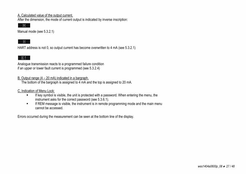
A, Calculated value of the output current. After the dimension, the mode of current output is indicated by inverse inscription: M
Manual mode (see 5.3.2.1) H
HART address is not 0, so output current has become overwritten to 4 mA (see 5.3.2.1) E!
Analogue transmission reacts to a programmed failure condition if an upper or lower fault current is programmed (see 5.3.2.4) B, Output range (4 – 20 mA) indicated in a bargraph. The bottom of the bargraph is assigned to 4 mA and the top is assigned to 20 mA. C, Indication of Menu Lock:
If key symbol is visible, the unit is protected with a password. When entering the menu, the instrument asks for the correct password (see 5.3.6.1).
If REM message is visible, the instrument is in remote programming mode and the main menu cannot be accessed.
Errors occurred during the measurement can be seen at the bottom line of the display.

28 / 48 wes1404a0600p_08
5.1.2. INFORMATION SCREENS Press button to cycle between the main measurement screen and the information display screen:
1. General information screen (DEV. INFO) Overall running time (OV. RUN TIME) Run time after power on (RUN TIME) Type of interface (INTERFACE) in the instrument. Type of the instrument (TYPE)
2. Sensor information screen: (SENSOR INFO) Number of echoes (ECHO TOT/SEL) Blocking (BLOCKING) Signal-to-noise ratio (SN) Temperature (TEMP)
3. Echo table: (ECHO TABLE)
The location (distance) and the amplitude of the echoes (Dist. / Amp.) are listed The listed items are the reflections detected by the PiloTREK (measured in dB) and the approximate distance from the process connection. The listed values are not accurate measurement values, since around the selected echo (measurement window) there are further measurements and signal processing procedures in order to provide accurate measurement display and level transmission.
The informative screen returns back to main screen after 30 seconds. By pressing the button the user can return to the main screen any time. Pressing the E button in any of the screens the user can enter the main menu. After exiting the menu always the main screen will be shown.
RUN TIME: 0.1hOV. RUN TIME: 1.0h
RELAY: YESINTERFACE: HART
- DEV. INFO ---0:1.00
LOGGER: NO
ECHO TOT/SEL: 01/01POS. OF WIND: 14SN RATION: 28BLOCKING: 10DMEM_BASE: 12TEMP: 26.2m/M TEMP: 0.00/26.2
--- SENSOR INFO -----
L:2.345m
m3Io: 12.00mA
200.000SIM
M
VOL 0F
--- ECHO LIST -----No. --Dist. – Amp. -00. 00.550 35.001. 00.000 00.002. 00.000 00.003. 00.000 00.004. 00.000 00.0

wes1404a0600p_08 29 / 48
5.1.3. ECHO MAP Pressing the button in the measurement screen the echo map screen will appear. This screen shows the following information:
1. Echo diagram
2. Actual measured distance
3. Maximal measuring range
The echo map screen returns back to main screen after 30 seconds. By pressing the button the user can return to the main screen any time. Pressing the E button in any of the screens the user can enter main menu. After exiting the menu always the main screen will be shown.
D:2177mm
mmIo: 12.00mA
2177M
DIST
2177mm 6000
ECHO MAP
Echo diagram
Measured distance
Maximal measuring range

30 / 48 wes1404a0600p_08
5.2. PROGRAMMING WITH THE SAP-300 DISPLAY MODULE When entering the menu, the instrument makes a copy of the actual parameters and all changes are done to this duplicated parameter set. During programming the instrument keeps measuring and transmitting with the current (and intact) parameter set. After exiting the menu the instrument replaces the original parameters with the new parameter set and will measure according to the new parameters. This means that the change of the parameters does not become immediately effective when pressing the E button! Entering the menu can be done by pressing the E button, while exiting the menu can be done by pressing the button. If the instrument is left in programming mode after 30 minutes it will automatically return to measuring mode. If the SAP-300 display is removed during programming the instrument immediately returns to measuring mode. As programming with SAP-300 (manual programming) and HART® (remote mode) programming is not possible at the same time, only one programming method could be chosen. Measured values can be read out through HART® at any time. 5.2.1. COMPONENTS OF THE PROGRAMMING INTERFACE The parameters of the instrument are grouped according to their functions. The programming interface consists of lists, dialog windows, edit windows and report windows. Lists Navigation between the lines of a list can be done by pressing the / buttons. Pressing the E button activates a list item. The selected list item is marked with inverse colour. Exit from a list by pressing the button. Menu list The Menu list is a specialized list. Its characteristic is that upon selecting a list item we directly get into another list, and these lists are opening from each other in different levels. The menu header (1) helps to navigate. Entering the main menu can be done by pressing the E button. Navigation between the menu items can be done by pressing the / buttons. Enter to the selected menu by pressing the E button. The selected list item is marked with inverse colour. Exit from a submenu by pressing the button. Pressing the button in the main menu will quit from the programming mode and the instrument will return to measuring mode.
MAIN MENUBASIC SETUP OUTPUT SETUP
CALCULATION
1
SERVICE
OPTIMIZATION

wes1404a0600p_08 31 / 48
Dialog window During the programming the system sends messages or warnings to the users by dialog windows. These usually can be acknowledged by pressing the button or the user can choose between two options (usually YES or NO) by pressing the / buttons. In some cases, one of the parameters has to be changed to correct an error.
WARNING LOAD DEFAULT TO PARAMETER TABLE! ARE YOU SURE?[YES] [NO]
Edit window An edit window is used for modifying a numeric parameter value. The selected character can be changed by pressing the / buttons. The cursor can be moved to left, by pressing the button. The direction of the cursor movement through the digits is right to left. The changed value can be validated by pressing the E button. The software checks if the entered value is appropriate, exiting from the edit window is only possible after entering a correct value. If the entered value is uninterpretable the software sends an error message in the bottom line (1) of the display.
ANALOG OUTPUTPARAMETER EDITOR
4mA VALUE:
m
WRONG VALUE!
16.0000
1 Edit window – button combinations In the edit window the following button combinations are available: 1. Recalling the parameters to the state before editing ( + , pressed for 3 sec.) 2. Recalling default parameters ( + , pressed for 3 sec.) 3. Inserting (currently) measured value to the edit window ( + , pressed for 3 sec.) Only for certain parameters!
E
2
13
5.2.2. MENU STRUCTURE Main menu BASIC SETUP Parameter group of the basic measurement parameters OUTPUT SETUP Parameter group of the output parameters OPTIMIZATION Parameter group for measurement optimization settings CALCULATION Calculations SERVICE Service functions, calibration, test and simulation

32 / 48 wes1404a0600p_08
5.3. PROGRAMMABLE FEATURES DESCRIPTION 5.3.1. BASIC MEASUREMENT SETTINGS 5.3.1.1 Default unit system Parameter: P00: c, where c: 0, 1. Default value: EU Path: BASIC SETUP / UNITS / ENGINEERING SYSTEM (for USA version: US) Description: This should be configured as the first step of the programming.
Here you can choose the default unit system: EU European unit system US Anglo-Saxon / American unit system
5.3.1.2 Dimension of the default unit system Parameter: P00: b, and P02: b, or P02: c Default value: mm, m3, t Path: BASIC SETUP / UNITS / ENGINEERING UNITS (for USA version: inch, ft3, t) Description: The dimension of the selected default unit system can be specified in this menu. The
selected measurement mode here will define the primary measured value and the displayed value, furthermore it will be the source for the current output:
BASIC UNITS (m, cm, mm, ft, inch) VOLUME / FLOW UNITS (m3, l, ft3, gallon) MASS UNITS (t, t) TOT UNITS (m3, l, ft3, gallon) TOT UNITS (sec, min, hour, day)
If the dimension is modified, the device resets all the parameters after a warning message.
5.3.1.3 Primary Value Mode Parameter: P01: b a Default value: LEVEL Path: BASIC SETUP / PV MODE Description: This mode determines the primary value and the displayed value. It also determines the
value which will be proportional to the output current. DISTANCE LEVEL VOLUME MASS

wes1404a0600p_08 33 / 48
5.3.1.4 Maximal Measuring Distance Parameter: P04 Default value: Path: BASIC SETUP / MAX. MEAS.DIST Description: This parameter should be entered all the cases, except distance measurement mode. But it
is suggested to be programmed in case of distance measurements in order to avoid the disturbing effects of possible unwanted multiple reflections!
5.3.1.5 Damping Time Parameter: P20 Default value: 15 sec Path: BASIC SETUP / DAMPING TIME Description: Damping time is used to damp the unwanted fluctuations of the output and display.
If the measured value changes rapidly the new value will settle with 1% accuracy after this set time. (Damping is according to the exponential function).
5.3.1.6 Demo Mode Parameter: P00: d Default value: OFF Path: BASIC SETUP / DEMO MODE Description: OFF: The operation is performed with considering all the application parameters
(such as filling, emptying speed, echo selection, etc.) ON: This fast operation mode ignores the application parameters. The demo
mode uses a fast algorithm evaluation independently from P25, P26 and P27 parameters. The measurement accuracy and reliable operation between process environments are not guaranteed!
5.3.2. ANALOGUE OUTPUT 5.3.2.1 Output Current Mode Parameter: P12: b, where b: 0, 1. Default value: AUTO Path: OUTPUT SETUP / ANALOG OUTPUT / CURRENT MODE Description: Transmission mode of the current output.
AUTO The output current is calculated from the measured value, output is active.
MANUAL The output current is fixed at a constant (set) value (see: 5.3.2.5). In this mode the setting of the error current is irrelevant. The set (current) value overwrites the 4 mA output of HART® multidrop mode!

34 / 48 wes1404a0600p_08
5.3.2.2 Output Current Value assigned to 4 mA Parameter: P10 Default value: 0 Path: OUTPUT SETUP / ANALOG OUTPUT / 4 mA VALUE Description: Measured value assigned to 4 mA current value.
The transmitted value is in accordance to the primary value (PV) (P01: a). Assignment can be done that the change in measured value and the change in the output value are the same (normal), or opposite directional (inverse operation). For example: 1 m (3.28 ft) level is 4 mA, 10 m (32.8 ft) level is 20 mA, or conversely.
5.3.2.3 Output Current Value assigned to 20 mA Parameter: P11 Default value: Path: OUTPUT SETUP / ANALOG OUTPUT / 20 mA VALUE Maximal measurement range Description: Measured value assigned to 20 mA current value.
The transmitted value is in accordance to the primary value (PV) (P01: a). Assignment can be done that the change in measured value and the change in the output value are the same (normal), or opposite directional (inverse operation). For example: 1 m (3.28 ft) level is 4 mA, 10 m (32.8 ft) level is 20 mA, or conversely.
5.3.2.4 Output Current Error Mode Parameter: P12:a, where a: 0, 1, 2 Default value: HOLD Path: OUTPUT SETUP / ANALOG OUTPUT / ERROR MODE Description: Error indication by the current output:
HOLD Error indication has no effect on the output current. LOW Error indication: the output current gets 3.8 mA. (Ex d[ia] type: 3.9 mA) HIGH Error indication: the output current gets 22 mA.
Warning: This error indication is active unless the failure is fixed, or until the failure terminates.
5.3.2.5 Fixed Output Current Parameter: P08 Default value: 4 mA Path: OUTPUT SETUP / ANALOG OUTPUT / MANUAL VALUE Description: Parameter for setting the fixed output current:
Values between 3.8 and 20.5 can be entered. The output current will be set to the entered value and analogue transmission will be suspended (see: 5.3.2.1). This error indication overrides all other error indication.

wes1404a0600p_08 35 / 48
5.3.3. DIGITAL OUTPUT 5.3.3.1 HART Polling Address Parameter: P19 Default value: 0 Path: OUTPUT SETUP / SERIAL OUTPUT / ADDRESS Description: HART Polling Address
The polling address can be set between 0 and 15. For a single instrument the polling address is 0 and the output is 4 – 20 mA (analogue output). If multiple units are used in HART® Multidrop mode (max. 15 pcs.) the polling addresses should differ from 0 (1 – 15), in this case the output current will be fixed at 4 mA.
5.3.4. MEASUREMENT OPTIMIZATION 5.3.4.1 Blocking, Dead Zone Parameter: P05 Default value: 300 mm Path: OPTIMIZATION / DEAD ZONE (For USA version: 11.8 inch) Description: The instrument ignores all reflections within the dead zone and the close-end blocking
distance. The disturbing objects and false reflections which are close to the sensor can be eliminated by entering the dead zone value manually.
5.3.4.2 Echo Selection Parameter: P25: a, where a: 0, 1, 2, 3 Default value: AUTO Path: OPTIMIZATION / ECHO SELECTION Description: Selection of Echo within the measuring window. In order to avoid disturbing reflections the
instrument forms a so-called measuring window around the reflected signal. The distance measurement is performed with the echo signal within the measurement window.
AUTO FIRST HIGHEST AMPLITUDE LAST
5.3.4.3 Emptying Speed Parameter: P27 Default value: 50 m/h Path: OPTIMIZATION / EMPTYING SPEED (For USA version: 164 ft/hr) Description: This parameter provides additional protection against echo loss in applications involving
very heavy fuming during emptying process. Correct setting increases the reliability of the measurement during the emptying. The parameter must not be smaller than the fastest possible emptying rate of the actual process. It could be maximum 90 m/h (295 ft/h).

36 / 48 wes1404a0600p_08
5.3.4.4 Filling Speed Parameter: P26 Default value: 50 m/h Path: OPTIMIZATION / FILLING SPEED (For USA version: 164 ft/hr) Description: This parameter provides additional protection against echo loss in applications involving
very heavy fuming during filling process. Correct setting increases the reliability of the measurement during the filling. The parameter must not be smaller than the fastest possible filling rate of the actual technology. It could be maximum 90 m/h (295 ft/h).
5.3.4.5 Background Image Parameter: OPTIMIZATION / BACKG.ECHO IMAGE / SAVE BACKG. IMAGE Path: The not-moving disturbing objects inside the tank which generates unwanted false
reflections can be blocked out from the measurement range. For this purpose the instrument needs to map the totally empty tank to create a ”background image”. After this procedure the software will automatically recognise and ignore the reflections coming from the disturbing objects crossing the microwave beam (see 4.1 – Obstacles). Warning! The background image should be saved only when the tank does not contain measurement medium but the disturbing objects inside the tank are not removed. The background image is not recommended to be saved when the tank is filled with the measurement medium since it might result wrong level measurement.
BACKGROUND IMG.
BKG. IMAGE YES
[QUIT] [SAVE]
[CLEAR]
Background is saved
Clear saved background
Save backgroundQuit
5.3.4.6 Using saved background image Parameter: P35: a, where a: 0, 1 Default value: OFF Path: OPTIMIZATION / BACKG.ECHO IMAGE / SAVE BACKG: IMAGE Description: Turning ON or OFF the usage of saved background image during the calculations as per
the above 5.3.4.5 point described. OFF: Ignoring the saved background image. ON: Saving background image, damping reflections coming from the disturbing objects.
5.3.4.7 Threshold value Parameter: P29 Default value: 4 dB Path: OPTIMIZATION / TRESHOLD VALUE Description: Defining an upper limit value above the saved background image described in 5.3.4.5 point.
The instrument will evaluate the measurement result as a real echo when the reflected signal exceeds the saved background level with the threshold value entered here. Setting the threshold value is useful when the level in the tank and the position of the (small surface) not-moving disturbing object are the same. This case the instrument will not regards the echo signal as false reflection.
wes1404a0600p_08 37 / 48
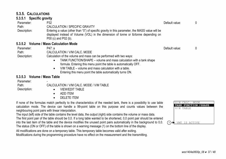
5.3.5. CALCULATIONS 5.3.5.1 Specific gravity Parameter: P32 Default value: 0 Path: CALCULATION / SPECIFIC GRAVITY Description: Entering a value (other than “0”) of specific gravity in this parameter, the MASS value will be
displayed instead of Volume (VOL) in the dimension of tonne or lb/tonne depending on P00 (c) and P02 (b).
5.3.5.2 Volume / Mass Calculation Mode Parameter: P47: a Default value: 0 Path: CALCULATION / V/M CALC. MODE Description: Calculation of the volume and mass can be performed with two ways:
TANK FUNCTION/SHAPE – volume and mass calculation with a tank shape formula. Entering this menu point the table is automatically OFF.
V/M TABLE – volume and mass calculation with a table. Entering this menu point the table automatically turns ON.
5.3.5.3 Volume / Mass Table Parameter: - Path: CALCULATION / V/M CALC. MODE / V/M TABLE Description: VIEW/EDIT TABLE
ADD ITEM DELETE ITEM
If none of the formulas match perfectly to the characteristics of the needed tank, there is a possibility to use table calculation mode. The device can handle a 99-point table on this purpose and counts values between the neighbouring point pairs with linear interpolation. The input (left) side of the table contains the level data, the output (right) side contains the volume or mass data. The first point pair of the table should be 0,0. If a long table wanted to be shortened, 0,0 point pair should be entered into the last item of the table and the device modifies the unused point pairs automatically in the background to 0,0. The status (ON or OFF) of the table is shown on a warning message (1) on the bottom line of the display.
V/M TABLE
V/M CALC. MODETANK FUNCTION /SHAPE
VMT IS ACTIVE1
All modifications are done on a temporary table. This temporary table becomes valid after exiting. Modifications during the programming procedure have no effect on the measurement and the transmitting.

38 / 48 wes1404a0600p_08
Entering the point pairs can be done in arbitrary order, because the device sorts according to ascending order. Both sides of the table have to be strictly monotonic increasing. In case of any error, warning message (see: 6th chapter) will appear. When entering again the table an inscription indicates the first wrong line. View table: In VIEW/EDIT TABLE menu point items of the ordered table can be checked. For moving in the list use the and buttons, for editing the selected item use the E button. Exiting from the list can be done by pressing the button.
01: 0000.0 000000 .000EDIT/VIEW TABLE
02: 0100.0 000100 .000
Edit table: Adding a point pair (ADD ITEM) to the list or pressing E button on an existing item, an edit screen will appear. In this edit screen there are two editing filed. Both editing field works as same as editing a parameter. Getting from the first field to the second field press the E button. Pressing E button in the second field will return back to the previous menu point. When exiting from the last field, the device performs the ordering of the table.
LEVEL VALUE : cm02. VM TABLE ITEM
095310.0000012.00
V/M VALUE: m3
Delete item Moving in the list can be done with and buttons, for deleting an item press the E button on the selected item. Exiting from the list can be done by pressing the button. The table should contain at least 2 items.
01: 0000.0 000000 .000DELETE ITEM
02: 0100.0 000100 .000
5.3.5.4 Tank Functions / Shape Parameter: P40: a, where a: 0,1, 2, 3, 4. Default value: 0 Path: CALCULATION / V/M CALC. MODE / TANK FUNCTION / SHAPE Description: STANDING CYL. – Standing cylindrical tank
STD. CYL. CON. BOT. – Standing cylindrical tank with conical bottom STD. RECT. W/CHUTE – Standing rectangular tank with or without chute LYING CYLINDRICAL – Lying cylindrical tank SPHERICAL – Spherical tank
5.3.5.5 Tank Bottom Shape Parameter: P40: b, where b: 0, 1, 2, 3 Default value: 0 Path: CALCULATION / V/M CALC. MODE / TANK FUNCTION / SHAPE Description: This menu only appears, if it has an importance on the selected tank shape type!
SHAPE0 SHAPE1
SHAPE2 SHAPE3

wes1404a0600p_08 39 / 48
5.3.5.6 Tank Dimensions Parameter: P41 – P45 Default value: 0 Path: CALCULATION / V/M CALC. MODE / TANK FUNCTION / SHAPE Description: DIM1 (P41)
DIM2 (P42) DIM3 (P43) DIM4 (P44) DIM5 (P45)
P41
b=0b=1
b=2b=3P40
Standing cylindrical tank with hemispherical bottom a = 0
P41
P43
P44
Standing cylindrical tank with conical bottom a = 1 ; b = 0
P41
P43
P44
Standing rectangular tank with or without chute a = 2 ; b = 1
P45
P42
If no chute: P43, P44 and P45 = 0
P41
b=0b=1
b=2b=3
P40
P42
Lying cylindrical tank a = 3
P41
Spherical tank a = 4 ; b = 0

40 / 48 wes1404a0600p_08
5.3.6. SERVICE FUNCTIONS 5.3.6.1 Security Codes User codes Path: SERVICE / SECURITY / USER LOCK Description: Setting or unlocking the user security code.
The instrument can be protected against unauthorized programming with a 4-digit PIN (Personal Identification Number) code. If either of the digits differs from 0 the code is active. If zero is specified, then the secret code has been deleted! In case of Active code, this code is requested at menu entry.
Service code Path: SERVICE / SECURITY / SERVICE LOCK Description: Setting of the service code.
Only for trained personnel! 5.3.6.2 Current Output Test Parameter: P80 Path: SERVICE / OUTPUT TEST / ANALOG OUTPUT / CURRENT VALUE Description: Loop current test (mA)
Entering this Parameter the current value which is proportional to the actual measurement value will appear on the display and the output. In loop current test mode, values between 3.8 and 22 can be entered. The output current will be set to the entered value. The measured current on the output should be equal to the set value. In test mode a dialog window warns the user of the fixed output current until the user exits the warning message window. Exiting can be done by pressing the E button.
5.3.6.3 Distance Simulation This function facilitates the user to be able to check the calculations (tank formula, table), outputs, and the additional processing instruments connected to the output. PiloTREK transmitters can perform simulation on the value of a constant or a variable. To start simulation the instrument must return to Measurement mode. In Measurement mode if simulation is in progress, an inverse SIM caption appears on the display.

wes1404a0600p_08 41 / 48
Simulation mode Parameter: P84: a, where a: 0, 1, 2, 3, 4 Default value: OFF Path: SERVICE / DIST SIMULATION / MODE Description: Simulation mode: OFF No simulation FIX VALUE Value of the simulated distance is set according to the lowest value of the simulation. MANUAL VALUE . . . . TRIANGLE WAVE Value of the simulated distance changes linearly between the
lowest and highest values with an adjustable cycle time.
Cycle timet [sec]
DIST
SQUARE WAVE The simulated value jumps between the lowest and highest
values with an adjustable cycle time.
Simulation cycle Parameter: P85 Default value: 60 sec Path: SERVICE / DIST. SIMULATION / TIME Description: Cycle time of the simulation
Bottom value of the simulation Parameter: P86 Default value: 0 Path: SERVICE / DIST. SIMULATION / BOTTOM VALUE Description: Lowest value of the simulation
Upper value of the simulation Parameter: P87 Default value: Programmed
measurement range
Path: SERVICE / SIMULATION / UPPER VALUE Description: Highest value of the simulation
5.3.6.4 Load Default Values Path: SERVICE / DEFAULTS / LOAD DEFAULT Description: This command loads all default values of the instrument.
After loading the default values the parameters can freely be changed, the effect of the changes does not affect on the measurement until the user exits from the Programming mode and returns to Measurement mode. Before loading the defaults the software asks for a confirmation from the user because all user parameters will be lost!

42 / 48 wes1404a0600p_08
6. ERROR CODES
MESSAGE ON THE SCREEN ERROR DESCRIPTION PROCEDURE TO DO CODE MEMORY ERROR Memory error Contact the service! 1 NO ECHO Sensor error Contact the service! 2 EE COM. ERROR Hardware error (EEPROM communication error) Contact the service! 3 MATH. OVERLOAD Calculation overflow Check the programming! 4
SIGNAL IN N.D.B. Sensor or calibration error (Measured value is in the close-end dead-zone) Contact the service! 5
SIGNAL IN F.D.B. Sensor or calibration error (Measured value is in the far-blocking zone) Check the installation conditions! 7
VMT SIZE ERROR Linearization error: Less than two items are in the table. Check the content of the VMT! See: 5.3.5.3. 12
VMT INPUT ERROR Linearization table error: monotonicity error in the input (level) side of the table. Check the content of the VMT! See: 5.3.5.3. 13
VMT OUTPUT ERROR Linearization table error: monotonicity error in the output (volume or mass) side of the table. Check the content of the VMT! See: 5.3.5.3. 14
VMT INPUT OV.RNG. Linearization table error: The measured level is greater than the highest level of the table’s input side.
Check the content of the VMT! See: 5.3.5.3. Device performs extrapolation according to the last point pairs!
15
EE CHK ERROR Parameter checksum error. Check the programming! For recalculate the checksum modify a parameter and return to Measurement mode. If this error still remains, contact the service!
16
INTEGRITY ERROR Parameter integrity error (Automatically corrected internal error). Only WARNING message.
Check the programming! 17
AC COM. ERROR Hardware error Contact the service! 18 CALIBRATION ERROR Sensor calibration error Contact the service!
Functions of information LEDs:
LED state „VALID” LED „COM” LED NOT LIT there is no appreciable echo no HART communication FLASHING SLOWLY (OR ONE FLASH) searching for echo within the valid measuring range flashes while HART communication is in progress CONTINUOUSLY LIT the selected echo is measured by the instrument programming on the HART line (remote) 6X SHORT FLASHES TOGETHER storage EEProm communication error has occurred 7X SHORT FLASHES TOGETHER Linearization table (VMT) error

wes1404a0600p_08 43 / 48
7. PiloTREK W-100 PARAMETER TABLE
Pxx Parameter name d c b a 00 Engineering system, dimensions DEMO mode
0 = Normal mode 1 = Demo mode
Engineering system: 0 = EU 1 = US
Dimension: (EU) 0 = m, 1 = cm, 2 = mm (US) 0 = ft, 1 = inch
01 Source of Primary Value (PV) 0 = DIST, 1 = LEVEL, 2 = VOLUME, 3 = MASS
02 Selectable dimensions TOT: (TOT-EU) 0 = m3, 1 = liter (TOT-US) 0 = ft3, 1 = US gallon
Time units: 0 = sec 1 = min 2 = hour 3 = day
(VOL/F-EU) 0 = m3, 1 = liter (VOL/F-US) 0 = ft3, 1 = US gallon (MASS-EU) 0 = tonne, 1= US tonne (MASS-US) 0 = tonne, 1 = lb(pound)
Temperature unit: 0 = °C
04 Max. measuring distance Maximal measuring distance of the level transmitter can be defined 05 Blocking / DEAD ZONE Minimal measuring distance within the ignores all the measurement values 08 Fix current output Fix forced value on the output current between 3.8 and 20.5 mA for loop current measuring purposes (operation mode = manual) 10 4 mA Measured and transmitted value (PV) assigned to 4 mA current value 11 20 mA Measured and transmitted value (PV) assigned to 20 mA current value 12 Output current mode Operation mode:
0 = AUTO 1 = MANUAL
Error indication of the current output: 0 = HOLD; 1 = LOW; 2 = HIGH
19 HART® polling address HART® Short Address of the level transmitter (0 – 15) 20 Damping time Damping time of the accurate transmitted (displayed) value in sec. after a high fluctuation in the measured value (0-999) 25 Echo selection in the measuring
window 0 = AUTO;
1 = FIRST 2 = HIGHEST AMPLITUDE 3 = LAST
26 Filling speed Rate of change of the measured value (when distance is decreasing) which can be just followed with the level transmitter 27 Emptying speed Rate of change of the measured value (when distance is increasing) which can be just followed with the level transmitter 29 Threshold value Threshold limit value (0 – 6 dB) for the received echo evaluation 32 Specific gravity of the medium Data for mass calculation

44 / 48 wes1404a0600p_08
Pxx Parameter name d c b a 35 Background mode Calculating with the saved background image:
0 = OFF 1 = ON
40 Tank shape 0 = Standing cylindrical tank with dome bottom
1 = Standing cylindrical tank with conical bottom
2 = Standing rectangular tank with or without chute
3 = Lying cylindrical tank 4 = Spherical tank
41-45 Tank dimensions 47 VMT mode Operation of the linearization:
0 = OFF, 1 = ON
60 Overall runtime Elapsed overall operating hours of the level transmitter (working time) with 0.1 hour accuracy. Service data 61 Runtime after last reset Elapsed operating hours of the level transmitter since the last turning ON with 0.1 hour accuracy. Service data 70 Number of echoes Service data 71 Position of the measuring
window Service data
74 Signal-to-noise ratio Service data 75 Blocking distance value Service data 80 Current output test Fix forced value on the output current between 3.8 and 20.5 mA for checking the accuracy of the current generator 84 Simulation Distance simulation mode:
0 = No simulation 1 = Fix value 2 = Simulation with a manual value: PV = a
entered in P86 3 = Simulation between P86 and P87 levels
with P85 cycle time (triangle wave) 4 = Simulation between P86 and P87 levels with P85 cycle time (square wave)
85 Cycle time of DIST simulation Cycle time of the distance simulation in seconds. Default value: 60 sec 86 Bottom value of the simulation Initial value of the distance simulation in the selected unit (e.g.: mm). Default value: 0 (mm) 87 Upper value of the simulation Final value of the distance simulation in the selected unit (e.g.: mm). Its default value is the same as the programmed maximal
measurement range.

wes1404a0600p_08 45 / 48
8. MENU MAP
MAIN
MEN
U
-----
------
------
---BA
SIC
SETU
POU
TPUT
SET
UPOP
TIMI
ZATI
ONCA
LCUL
ATIO
NSE
RVIC
E
BASI
C SE
TUP
------
------
------
--UN
ITS
PV. M
ODE
MAX.
MEA
S. D
IST
DAMP
ING
TIME
DEMO
MOD
E
UNIT
S
------
------
------
--EN
GINE
ERIN
GSY
STEM
ENGI
NEER
ING
UNIT
S
ENGI
NEER
ING
SYST
EM
------
------
------
--EU US
BASI
C UN
ITS
------
------
------
--ME
TER
/ FT
CM / I
NCH
MM
OUT
PUT
SETU
P
------
------
------
--AN
ALOG
OUT
PUT
SERI
AL O
UTPU
T
PV. M
ODE
------
------
------
--DI
STLE
VEL
VOLU
MEMA
SS
ENGI
NEER
ING
UNIT
S
------
------
------
--BA
SIC
UNIT
SVO
LUME
UNI
TSMA
SS U
NITS
VOLU
ME U
NITS
-----
------
------
---m
/ ft
LITER
/ GAL
LON
33
MAS
S UN
ITS
---
------
------
-----
METR
. / IM
P. TO
N- /
lb (P
OUND
)
MAX.
MEA
S DI
ST.
DAMP
ING
TIME
DEMO
MOD
E
------
------
------
--OF
FON
ANAL
OG O
UTPU
T
------
------
------
--CU
RREN
T MO
DE4m
A VA
LUE
20mA
VAL
UEER
ROR
MODE
MANU
AL V
ALUE
SERI
AL O
UTPU
T
------
------
------
--AD
DRES
S
CURR
ENT
MODE
------
------
------
--AU
TOMA
NUAL
4mA
VALU
E
20m
A VA
LUE
ERRO
R MO
DE
------
------
------
--HO
LDLO
WHI
GH
MANU
AL VA
LUE
ADDR
ESS

46 / 48 wes1404a0600p_08
OPTI
MIZA
TION
---
------
------
-----
DEAD
ZON
EEC
HO S
ELEC
TION
FILL
ING
SPEE
DEM
PTYI
NG S
PEED
BACK
G. E
CHO
IMAG
ETR
ESHO
LD V
ALUE
DEAD
ZON
E
ECHO
SEL
ECTI
ON
------
------
------
--AU
TOFI
RST
HIGH
EST A
MPLIT
UDE
LAST
FILL
ING
SPEE
D
EMPT
YING
SPE
ED
BACK
G. E
CHO
IMAG
E
------
------
------
--SA
VE B
ACKG
. IMAG
EMO
DEMO
DE ---
------
------
-----
ON OFF
TRES
HOLD
VALU
E
MAX.
MEA
S. D
IST.
SPEC
IFIC
GRA
VITY
CALC
ULAT
ION
---
------
------
-----
MAX.
MEA
S. D
IST
V/M
TABL
E**S
PECI
FIC
GRAV
ITY
V/M
CALC
. MOD
E
V/M
CALC
. MOD
E
------
------
------
--TA
NK F
UNCT
ION/
SHAP
E
TANK
FUN
CTIO
N/SH
APE
---
------
------
-----
STAN
DING
CYL
.ST
D. C
YL. C
ON. B
OT.
STD.
REC
T. W
/CHU
TELY
ING
CYLIN
DRIC
ALSP
HERI
CAL
BOTT
OM S
HAPE
---
------
------
-----
SHAP
E 0
SHAP
E 1
SHAP
E 2
SHAP
E 3
TANK
DIM
ENSI
ON
------
------
------
--DI
M 0
DIM
1DI
M 2
DIM
3DI
M 4
DIM
5
DIMx
V/M
TABL
E
------
------
------
--VI
EW/E
DIT
TABL
EAD
D IT
EMDE
LETE
ITEM
BACK
GROU
ND IM
G. D
IALO
G[S
AVE]
, [CLE
AR]
MODI
FY?
"ARE
YOU
SUR
E?"

wes1404a0600p_08 47 / 48
SERV
ICE
---
------
------
-----
SECU
RITY
OUTP
UT T
EST
DIST
SIM
ULAT
ION
DEFA
ULTS
REST
ART
SECU
RITY
---
------
------
-----
USER
LOCK
SERV
ICE
LOCK
OUTP
UT T
EST
---
------
------
-----
ANAL
OG O
UTPU
TSE
RIAL
OUT
PUT
DIST
SIM
ULAT
ION
---
------
------
-----
MODE
TIME
BOTT
OM VA
LUE
UPPE
R VA
LUE
DEFA
ULTS
---
------
------
-----
LOAD
DEF
AULT
REST
ART
---
------
------
-----
USER
LOC
K
SERV
ICE
LOCK
CURR
ENT
VALU
E
SERI
AL O
UTPU
T
------
------
------
--12
00Hz
2200
Hz
MODE
------
------
------
--OF
FMA
NUAL
VAL
UETR
IANG
LE W
AVE
SQUA
RE W
AVE
TIME
BOTT
OM VA
LUE
UPPE
R VA
LUE
LOAD
DEA
FULT
?"A
RE Y
OU S
URE?
"
**SER
VICE
DIS
T OF
FSET

48 / 48 wes1404a0600p_08
wes1404a0600p_08
November 2019 NIVELCO reserves the right to change technical data without notice!