Embed Size (px)
Citation preview

NIT No. 12/OMC/MAT/16 Dtd. 07.12.2016
TENDER FOR PROCUREMENT OF HT APFC PANEL
OMC invites tender for supply & installation of HT Automatic Power
Factor Correction (APFC) Panel for Daitari Mines of OMC. The details of the
tender schedule, place of installation & eligibility criteria are available in
our website i.e. www.omcltd.in which should be downloaded by the
interested bidders. There will be no manual sale of the tender paper. The
last date for receipt of tender in the office of the undersigned is
23.12.2016 up to 3:00P.M.which will be opened on the same day at
3.30P.M.
OMC reserves the right to accept/ reject all or a part of the tenders
without assigning any reason thereof.
Addl.General Manager (Materials)
1. INTRODUCTION
Registered Office: OMC House, Bhubaneswar- 751001, Inel: 0674-2377400, 2377401, Fax: 0674-2396889, 2391629, www.omcltd.in
CIN: U13100OR1956SGC000313

1. INTRODUCTION:- OMC intends to install HT 1200KVAR APFC Panel-1no at its Daitari Mines in the dist. Of Keonjhar,Odisha. Important Information (Time Schedule) Bid Reference NIT NO .12/OMC/AGM(MAT)/16, Dt.07.12.16
Date of Commencement of availability of bidding Document
There will be no manual sale of Bidding Document. The Document is to be downloaded from the OMC website i.e. www.omcltd.in
Last date for availability of bidding Document.
The document shall be available in the OMC web site till 23.12.2016 up to2.00 P.M. The tender shall be down loaded from this web site by the interested bidders.
Last date and time for submission of bid
23. 12.2016 up to 3.00 P.M.
Time and date of opening of Bids Techno commercial bid Price Bid
23. 12.2016 at 3.30 P.M. To be intimated separately to the eligible bidders.
Place of opening of Bids Office of the AGM (Material), OMC Ltd Bhubaneswar.
Cost of Tender Paper Rs.2,000.00 + 5% VAT= Rs 2100.00
EMD
Rs 10,000.00( Rupees ten thousand only)
Address for Correspondence Addl. General Manager (Materials) The Odisha Mining Corporation Ltd. OMC House, Bhubaneswar PIN-751 001, Odisha, India Ph- 0674-2391876 [email protected]

2. REQUIREMENT OF APFC PANEL WITH QUANTITY
Sl.No. Description Qty in no. 1. 11KV,1200KVAR APFC Panel at Daitari Mines in the
dist of keonjhar, Odisha 01
OMC reserves the right to vary quantity.
3. The detailed scope of work shall include: a) Visit to site to ascertain the actual materials requirement including civil
foundation and electrical materials etc for complete installation and
commissioning.
b) Structure including civil foundation for 11KV APFC panel.
c) Design, manufacture and supply all materials for the APFC Panel.
d) OMC shall not supply any material for this work.
e) Loading, insurance, transportation and unloading as required.
f) Erection, testing and commissioning of APFC Panel.
g) Performance guarantee tests on completion of commissioning
h) All the APFC Panel are indoor type.
i) It is the responsibility of the successful bidder to get the installation
approved of the HT APFC Panel from the statutory authority of that area.

1. Technical specification:-
1.1 Specification of 11KV, 1200KVAR INDOOR APFC PANEL
CAPACITOR BANK Parameters:-
Sl. No. Item Specification 1 Nominal system voltage 11KV 2 Rated voltage of capacitor bank 12.65 KV 3 Output of capacitor bank at 12.65 KV 1200 KVAR 4 Rated line current 100 Amp 5 Connection of capacitor bank Single star 6 No. of phases 3
7 Rated voltage of individual capacitor unit 7.3 KV
8 Capacity of individual capacitor unit 100:150 & 200 KVAR 9 Insulation level RMS-28 KV & Peak-95 KV
10 Maximum temp. rise over ambient measured on container 10 0 C
11 Type of discharge Internally through resistor provided within the unit
12 Type of fuse External/ Internal fuse 13 Type of Installation Indoors
14 Power Loss (Tan Delta) Not to exceed 0.2 watt/KVAR subject to tolerance as per standard.
RATING
Sl. No. 11KV rating Capacitor Bank rating at 12.65 KV
Step configuration KVAR X No. of units
I. 3150 KVA 1200 KVAR 300 x 2 + 600 x1

TECHNICAL SPECIFICATION 11KV (INDOOR) AUTOMATICALLY SWITCHED SHUNT CAPACITOR BANKS ALONG WITH 11 KV CAPACITOR CONTROL PANEL AT 33/11KV
SUB-STATION SPECIAL INSTRUCTIONS TO BIDDER FOR 1200KVAR APFC PANEL Please read following instructions carefully before submitting your bid.
1. In order to ascertain the highest reliability of system offered, the bidder shall be a manufacturer of critical components of the system, viz. Capacitor Banks or Automatic Power Factor Controller or Vacuum Capacitor Switches.
2. The Bidder shall execute the work on TURN KEY basis i.e. design, engineering, manufacture, testing at manufacturer’s works, supply and delivery, erection, testing and commissioning of 11kV Automatically switched (Indoor type) Capacitor banks along with the accessories including Civil works. The design calculation sheet for fixing of Capacitor Bank with capacity to improve p.f. From 0.8 to unity shall also be submitted.
3. The bidder shall have to submit all the required type test reports for the offered item. However, in the event of partial submission or reports older than specified limit, bidder must submit his confirmation for those type test report/s to be submitted in the event of an order, without affecting delivery schedule, before commencement of supply, free of cost. In absence of this confirmation, the evaluation shall be carried out accordingly as non submission of type test reports.
4. Bidder has liberty to visit the site to ascertain the quantum of works required to be taken up before quoting of price.
1. SCOPE:
1.1 This Scope covers design, engineering, manufacture, testing at manufacturer’s works, supply and delivery, erection, civil works including testing and commissioning of Indoor type medium voltage three phase automatic capacitor bank consisting of three steps of Capacitor Banks depending upon KVAR requirement at 11KV. All controls, switching devices, and protection features are enclosed in a sheet steel enclosure. The banks shall come fully suitable for Indoor installation on structure along with the necessary equipments in all respects.
1.2 The specification covers 3 phase, 50 Hz, Indoor type automatically switched shunt capacitor bank intended for installation at 11 KV feeders of 33/ 11 KV power transformer in sub-station. It also includes Leveling of site, excavation of pits, casting of foundation for elevating structures on concrete plinth and other mounting structures as applicable as per approved drawing, erection, elevating structure and mounting rack, painting wherever required, assembling of capacitor units on the rack, individual connection to make bank formation. The equipment covered in this specification comprises Capacitor banks in steps, 0.2 % Series Reactors, CRCA Cubicle, Vacuum switches/contactors, HT Fuses, RVT, CT/NCT, VCB, CRP, Isolator, LA, Power & Control cables and its termination along with suitable terminal connectors, Conductors, foundation bolts and earthing connection materials for all equipments & structures etc.

1.3 It is not be the intent to specify completely here in all the details of design & construction of material. However the material shall conform in all respects to high standards of Engineering, design and workmanship operation in manner acceptable to the purchaser, who will interpret the meanings of drawings and specification and shall have the power to reject any work or material which in his judgment is not in accordance therewith. The offered material shall be complete with all components necessary for their effective and trouble free operation. Such components shall be deemed to be within the scope of bidders supply irrespective of whether these are specifically brought out in his specification and / or purchaser order or not.
1.4. In order to ascertain the highest reliability of system offered, the bidder shall be a
manufacture of critical components of the system, viz. Capacitor Banks, Automatic Power Factor Controller and Vacuum Capacitor Switches.
1.5 Requisite size of rubber mats of 5mm thickness are to be laid around the panel as
per statutory requirement.
1.6 Laying of earth mat (75X10 mm GI Flat) and other earth riser (50 X 6 mm GI Flat) tothe equipment and structural (50X6 mm GI Flat) and treated earth pit are also under the scope of this contract.
2. CLIMATIC CONDITION: 1. Max. ambient air temperature 50º C 2. Min. ambient air temperature 5º C 3. Average Daily Max. ambient temperature 35º C 4. Max. altitude above mean sea level (Meters) 1000 5. Minimum Relative Humidity (%age) 30 6. Max. Relative Humidity (%age) 95 7. Avg. No. of Rainy days/year 120 8. Avg. annual rainfall 1000 mm 9. Wind Zone, Maximum wind pressure Zone- V, 50 m/sec.
3. APPLICABLE STANDARD:
ISS No. TITLE 13925 : 1998 or IEC 60871 Specification for H.T, Shunt Capacitor
IS 9920-2002 Vacuum Contactors/Capacitor Switch IS 9921-1985 Isolator
IS 2705 Current Transformer IS 3070 Lighting Arrestor IS 3156 R.V.T IS 5553 Series Reactor
IEC 61000 Automatic Power Factor Controller The other components such as Vacuum Circuit Breaker Panel and other Auxiliary equipment shall comply with the latest version of relevant Indian Standards/ International standards.

Equipment conforming to other internationally accepted standards which ensure equal or higher quality than the above mentioned standards would also be acceptable. In such case bidders, who wish to offer material conforming to standards other than listed above, shall clearly bring the salient points of difference between the standards forward/adopted and specified herein above. Four copies of such standards with authentic English Translation shall be furnished along with the offer. In case of conflict order of preference shall be (1) ISS (2) IEC (3) other standards. In case of any difference between provisions of these standards and provision of this specification of the provision contained in this specification shall prevail. All IS/IEC shall be read with latest amendments in vogue on the date of technical bid opening.
4.0 11KV CAPACITOR BANK
4.1 SCOPE: The capacitor banks are for use in a 3 phase ,50 Hz 11 KV system. Capacitor bank shall consist series/parallel combination of small units of capacitor cells per phase, each with an out put rating of 100 or 150 or 200 or 400 KVAR or any other combination of 7.3 KV single phase. Capacitor units should be connected in externally star with appropriate number of capacitors in parallel as per requirement to achieve p.f. to the level of 0.95 to 1.0. For Example 3 single units connected in star to obtain 300/600 KVAR at 12.65 KV 3 phase or 2 capacitors units of 150 kvar in parallel per phase with 3 phase connection in star to obtain 600 or 1200 or 900 KVAR at 12.65 KV 3 phase. Necessary number of steps should be provided to meet requirement given in the schedule.
i. Each capacitor unit should be provided with external / internal expulsion fuse 12KV class and suitable current rating. Capacitor shall meet following specifications:
ii. Each capacitor unit shall have scaled sheet steel container with suitable mountingbracket which can easily be fixed to frame structures. The container shall be built from heavy gauge Stainless Steel, 1.6 mm thick sheet steel with welded seams, mechanically strong, rigid and hermetically sealed. The container of capacitor Unit shall be designed to allow for expansion and contraction due to all ambient & loading conditions expected during the life of the unit.
iii. The capacitor elements shall be thoroughly dried and impregnated with an impregnant that has been completely refined so as not to leave any gas or impurities which may cause deterioration of the dielectric. The impregnant used shall have low viscosity and high chemical stability. It should be non-PCB (NPCB). It shall be incombustible and have a high dielectric constant. Capacitor dielectric shall be 100% polypropylene. However, in case of 100% polypropylene capacitor the polypropylene shall be hazy and aluminum foil should be embossed for proper impregnation. The Characteristics of the oil used for impregnation shall be furnished in the bid. The total thickness of dielectric (excluding aluminum foil) should be clearly indicated in the bid. The nos of layers of dielectric shall be three ofmore. The details of aluminum foil shall also be furnished. The impregnation shall be carried out under high vacuum & unit shall be totally sealed. The raw material to be used for manufacturing of capacitor unit i.e. polypropylene film, non PCB non toxic oil and aluminum foil shall be of best quality. List of raw material sources shall be submitted with technical bid.

iv. Each unit shall have two bushing for terminal connection. The rating of bushing should not be less than 15 kV, suitable for series / parallel connection with other units to form capacitor bank at 50 Hz. The bushing shall be of porcelain suitable for heavily polluted atmosphere having required creepage distance not less than 375 mm.
v. The capacitor shall have low value of loss which shall not exceed 0.2 watt per KVAR.
The losses in watts for each capacitor unit including losses in fuses and discharge resistors forming integral part of the capacitors along with losses for series reactor shall be guaranteed. If these figures of capacitor losses exceed 0.2W/KVAR, the capacitors will be liable for rejection.
vi. Capacitors having self healing property MPP Technology with some addedfeature can
be preferred.
vii. Total losses shall be complied as below:
6 x (W x n + losses in series reactor) Where, n is number of capacitor units per phase of star connection and W is the total loss in a capacitor unit. The loss temperature characteristics, capacity temperature characteristics and insulation resistance temperature characteristics shall also be furnished. The use of P.C.B. as dielectric for capacitor shall not be acceptable. The dielectric medium to be used shall be nonpoisonous and non-toxic in nature and shall not cause pollution of environment.
Sl No. Item Specification 1 Nominal system voltage 11 KV 2 Rated voltage of capacitor bank 12.65 KV 3 Output of capacitor bank at 12.65 KV 1200 KVAR 4 Rated line current 100 Amp 5 Connection of capacitor bank Single Star 6 No. of phases 3 7 Rated voltage of individual capacitor 7.3 kV
unit 8 Capacity of individual capacitor unit 100;150 & 200 KVAR 9 Insulation level RMS-28 KV
Peak-95 KV
10 Maximum temp. rise over ambient measured on container 10º C
11 Type of discharge Internally though resistor provided within the unit
12 Type of fuse External / Internal fuse 13 Type of Installation Indoors 14 Power loss (Tan delta) Not to exceed 0.2 watt/KVAR
subject to tolerance as per standard

4.2 Capacitor Bank Rating:
Sl. No 11kV Rating Capacitor Bank Rating at 12.65 KV
Step configuration KVArx No. of units
I. 3150 KVA 1200 KVAR 300x2+600x1 Each capacitor unit shall be provided with external / internal HT HRC fuse of 12 KV class with suitable current rating. Capacitor shall meet following specifications:
4.3 Temperature Category: The capacitor shall be suitable for operation with upper limit of ambient temperature 60ºC.
4.4 Rated Voltage: The rated voltage of 3 phase capacitor banks shall be 11 KV (phase to phase) and
maximum operational voltage shall be rated for 12.65 kV.
4.5 Rated Output: The Rated output of 3 phase capacitor banks shall be 600, 1200, KVAR at the
maximum operational voltage of 12.65 KV intended for use in suitable combination on power transformer rating of 3.15 MVA. The standard basic unit rating of capacitors (single phase) shall be 100/150/200KVAR. The unit shall be connected in externally star formation with floating neutral.
(i) Voltage: The maximum rms voltage that may safely be applied to the capacitor, ratedfor continuous duty, shall not exceed the rated rms voltage of the capacitor by more than 10%, and its peak or crest value shall not exceed the same rms voltage by more than 56%.
(ii) Current: The capacitor unit shall be suitable for continuous operating at
rmslinecurrent not exceeding 30 percent over the current which would flow through capacitors at + 10% rated voltage and + 1% to - 5% rated frequency. (50 HZ).
(iii) Discharge: Each capacitor unit shall contain a directly connected internal
discharge resistors, which shall be capable of reducing the residual voltage from crest value of the rated voltage to 50 volts or less within 5 minutes after the capacitor is disconnected from the source of supply. Time of quick switching on & off shall be specified. During quick switching on and off, the discharge device shall reduce the residual voltage to 10% or less of the rated voltage between switching on and switching off operations
4.6 Permissible Overloads: For capacitor covered in this specification, the maximum permissible overloads with
regard to voltage, current and reactive output shall not exceed the limits specified in IS:13925.
4.7 Power Loss: The power loss in capacitors shall not exceed 0.2 watt / KVAR (Subject to tolerance of
+ 10 %).
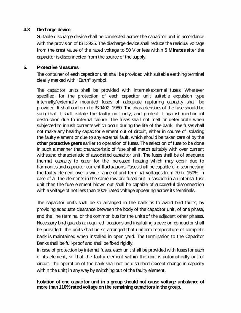
4.8 Discharge device: Suitable discharge device shall be connected across the capacitor unit in accordance
with the provision of IS:13925. The discharge device shall reduce the residual voltage from the crest value of the rated voltage to 50 V or less within 5 Minutes after the capacitor is disconnected from the source of the supply.
5. Protective Measures The container of each capacitor unit shall be provided with suitable earthing terminal clearly marked with “Earth” symbol.
The capacitor units shall be provided with internal/external fuses. Wherever specified, for the protection of each capacitor unit suitable expulsion type internally/externally mounted fuses of adequate rupturing capacity shall be provided. It shall conform to IS-9402: 1980. The characteristics of the fuse should be such that it shall isolate the faulty unit only, and protect it against mechanical destruction due to internal failure. The fuses shall not melt or deteriorate when subjected to inrush currents which occur during the life of the bank. The fuses shall not make any healthy capacitor element out of circuit, either in course of isolating the faulty element or due to any external fault, which should be taken care of by the other protective gears earlier to operation of fuses. The selection of fuse to be done in such a manner that characteristic of fuse shall match suitably with over current withstand characteristic of associated capacitor unit. The fuses shall be of adequate thermal capacity to cater for the increased heating which may occur due to harmonics and capacitor current fluctuations. Fuses shall be capable of disconnecting the faulty element over a wide range of unit terminal voltages from 70 to 150%. In case of all the elements in the same row are fused out in cascade in an internal fuse unit then the fuse element blown out shall be capable of successful disconnection with a voltage of not less than 100% rated voltage appearing across its terminals. The capacitor units shall be so arranged in the bank as to avoid bird faults, by providing adequate clearance between the body of the capacitor unit, of one phase, and the line terminal or the common bus for the units of the adjacent other phases. Necessary bird guards at required locations and insulating sleeve on conductor shall be provided. The units shall be so arranged that uniform temperature of complete bank is maintained when installed in open yard. The termination to the Capacitor Banks shall be full-proof and shall be fixed rigidly. In case of protection by internal fuses, each unit shall be provided with fuses for each of its element, so that the faulty element within the unit is automatically out of circuit. The operation of the bank shall not be disturbed (except change in capacity within the unit) in any way by switching out of the faulty element. Isolation of one capacitor unit in a group should not cause voltage unbalance of more than 110% rated voltage on the remaining capacitors in the group.

6.0 General Requirements: The capacitor shall be of non-PCB type, using polypropylene film as the dielectric. Complete mounting brackets supporting insulators and all other components for formation of capacitor banks racks shall be supplied along with the capacitor units. Necessary foundation bolts/nuts shall also be supplied. The outside of the capacitor container and other structures should have smooth and tidy look and should be coated with the weather proof, corrosion-resistant paint of white or light grey. Marking: The capacitor unit shall be provided with a rating plate and terminal markings as stipulated in IS: 13925. The bidder shall submit the type test report along with the bid for the ratings offered or higher ratings of individual units.
7.0 TESTS: The bidder shall submit the type test report along with the bid.The switched
capacitors shall be subjected to allthe type, routine and acceptance test in accordance with IS: 13925.
8.0 AUTOMATIC CONTROL UNIT (ACU)
8.1 Switching Arrangement The Automatic control unit shall be provided inside the control room to continuously monitor total KAVR requirement on secondary side of the transformer and shall automatically switch ON or switch OFF the capacitor banks through the operation of 12 KV Capacitor Switch.. Overriding provision shall be made for electrical switching ON or OFF of the capacitor switch by the operator from the ACU control box. The Power factor controller will automatically switch equal or unequal capacitor bank stages in or out to regulate the System power factor to a preset value. The controller shall monitor individual stages for loss in kvar, and shall continue to regulate to a preset value in the event there is a defective stage
8.2 Time Delay: An interposing factory set on-delay shall be provided to prevent the energization of a capacitor bank in less than 10 minutes. The manufacturer of the bank shall confirm that when going from the “Manual” position to the “Auto” position on any stage, that the corresponding stage will not be energized in less than 10 minutes. The switching OFF operation of relevant steps will be instantaneous.
8.3 Controls The Automatic control unit shall instantly switch OFF the incomer VCB of capacitor bank in the following contingencies occurring in any of the phases. a) Voltage increased by 10% above the rated voltage of 11 KV. b) Power transformer current impedance (due to single phasing and for any other
reasons) between any of the two phases exceeding 20 % of the lowest. c) Current increases in any capacitor unit by 30% above the rated current (only
the relevant capacitor switch will open). Current between any of the two phases of the capacitor bank differs more than 15% of the lowest current of the 3 phases (only the relevant capacitor switch will open).

8.4 Monitoring Facility: A suitable ammeter with selector switch to indicate the capacitor current in each phases of the capacitor bank shall be provided on the ACU panel inside the control room. Indicating lamps will also be provided to indicate ON & OFF status of each capacitor bank.
In addition, the controller shall consist of the following features:
Digital setting of individual parameters including target power factor, switching time, no. of steps, etc.
Digital indication of preset power-factor, preset parameters, and specified installation data.
Facility to Connect a Mini printer.
Plug-in Terminal Connection.
Automatic elimination of defective capacitor steps and their indication on the LCD display as also by LED indicators on the front fascia of the Controller.
Visual Display of Harmonic Overload Alarm
A counter that counts the number of times each stage has been energized shall be provided. Each stage shall be equipped with on/off/auto switches, stage on indicator (green) and stage faulty indicator (red).
8.5. Control Power: The DC control voltage for operation of the ACU shall be made by the bidder at its own cost. The AC supply is from (230 V) Station Transformer.
8.6 Temperature Variation: The control equipment and associate circuitry shall be suitable for operation at an
ambient temperature in the range of +5º C to (+) 60º C. 8.7 Protection of ACU: Besides in-built protection against lines surges and transient over voltages, suitable
fuses/MCBs shall be provided for protection against over current. The ACU shall remain fully functional during and after line surges and transient over voltages.
8.8 Control Unit Casing: Except for the terminals, the ACU shall be enclosed in a suitable casing so as to avoid
ingress of dust. 8.9 TESTS The Automatic Power Factor Controller must be Type tested for Accuracy and for
compliance to EMI/EMC to the relevant standards in any International Lab. Accredited Cooperation (ILAC). or an external NABL accredited laboratory. The Type test report shall be submitted along with the Tender & the same shall not be more than 5 yearsold on the date of Tender opening.

9.0 11 kV CAPACITOR SWITCHES 9.1 SCOPE This specification covers 11 KV, 50 Hz, out-door type automatic capacitor switches
suitable for switching capacitor banks of 300 KVAR, 600 KVAR and 1200 KVAR ratings or any other higher rating specified.
9.2 APPLICABLE STANDARDS Unless otherwise stipulated in this specification the capacitor switch shall comply
with the latest version of IS:9920 (AC Switches for voltages above 1000 V). Capacitors should be tested by International Laboratories as per IEC : 60265-1 (1998) 9.3 RATED VOTAGE The rated voltage for the capacitor switch shall be 12 KV.
Thisrepresents the highest system voltage corresponding to the nominal system voltage of 11 KV.
9.4 RATED CURRENT The standard rated normal current shall be 200A.
9.5 RATED CAPACITIVE SWITCHING CURRENT The rated capacitive switching current shall not be less than 50A. Note: The
capability of the switch shall also take into account the parallel switching of capacitor bank steps.
RATED SHORT TIME CURRENT
The rated short time symmetrical current for 1 second shall be 10KA (rms A.C. component).
9.7 RATED MAKING CURRENT The rated making current shall be 2.5 times the rms value of the a.c. component of
rated short time capacity. 9.8.1 BASIC IMPULSE LEVEL (BIL) The rated basic impulse level of switch to earth as also across the open terminals
shall be 75KV. 9.9 CONTROL SUPPLY
The control power for closing the switch shall be 230 V single phase AC supply. The closing mechanism shall be suitable for a voltage variation of (+) 10% to (-)20%.
9.10 DESIGN & CONSTRUCTION REQUIREMENSTS
a) TYPE: The switches shall be of either vacuum or SF6 type. b) The capacitor switches shall be of three phase construction and shall be suitable
for remote operation.

c) The capacitor switch shall be suitable for Indoor installation and shall have sealed weather proof type construction.
d) The capacitor switch shall be provided with a mechanical indicator to show
whether the contact is in open/closed position, locally, as also through indication on the ACU panel. Provision shall also be made for manual closing and opening.
e) The metallic enclosure of the capacitor switch shall be provided with two
earthing terminals marked with the earth symbol. f) The bushing provided on the switch shall have clamp type of terminals to directly
receive aluminium conductors up to 10mm dia in both horizontal and vertical directions. The terminal arrangement shall be such as to avoid bimetallic corrosion.
9.11. OPERATING MECHANISM
The operating mechanism shall be either solenoid or motor charged spring for which the control supply shall be made by the bidder.
9.12 MECHANICAL AND ELECTRICAL ENDURANCE The switch shall be capable of performing not less than 10,000 mechanical operations and 10,000 electrical operations at 50A capacitive current without getting damaged.
9.13 TESTS The Capacitor switch shall be subjected to the following tests in accordance with the IS:9920 (Part-IV) &also should be tested by International Lab. AccreditedCooperation (ILAC)as perIEC : 60265-1 ( 1998
10.0 AUXILARY EQUIPMENTS
10.1 TECHNICAL SPECIFICATION FOR 11 KV ISOLATOR SCOPE This specification provides for design, manufacturer, testing at manufacturer’s Works and delivery,supervision of erection, commissioning(if required )of Indoor station type 11 KV, 3 phase triple pole double break gang operated centre rotating type (Single Isolator with earth switches, with electrical inter lock (castle key), insulators and complete in all respect with bimetallic connectors arcing horns operating mechanism, auxiliary switches, indicating devices, fixing detail etc. as described hereinafter. Double Tandem operating GI pipes (40mm Dia. medium gauge) & down pipe of 50mm dia, medium gauge GI pipe has to be used. Isolator should be of Switchgear and Structurals, CGL/ GR POWER/ AREVA/SIEMENS/ EPICAST make.

10.2 Main features Sl.
No. Type 11 KV
1. Main switch Double end break center post rotating, gang operated
2. Service Indoor 3. Applicable standard - IS : 9921 / IEC-129/IEC-62271-102. 4. Pole : 3 pole gang operator
5. Rated voltage nominal / Maximum (kV) 11/12
6. Rated Frequency 50 HZ + 5% 7. System earthing effectively earthed 8. Temperature rise As per relevant IS/IEC publication 9. Insulation level impulse with
stand voltage :
a) Across Isolating distance(kV peak) 85
b) To earthed & between poles(kV Peak) 75
10. 1 minute power frequency with stand voltage
a) Across Isolating distance(kV Peak) 32
b) To earthed & between poles(kV Peak) 28
11. Rated current 800 12. Short time current for 3 sec. 25KA 13. Operating mechanism Manual 14. Auxiliary voltage 11 KV
a) Control & Inter lock 24V DC 80% to 110% 15. Safe duration of overload
150% of rated current 5 minute 120% of rated current 30 minute
16. Minimum creepage distance of support and Rotating insulator 500mm
a) Mounting structure Upright on G.I structure b) Terminal connector type Bimetallic clamp size as per Requirement c) Control Local
REMARKS: The operating mechanism for earth switch 11 KV shall be operated manually.
10.3 STANDARDS Disconnecting switches covered by this specification shall conform to latest edition IEC-129/IEC 62271-102 I.S.1813 and IS: 9921,IS-325,and unless specifically stated otherwise in this specification.

10.4 TYPE The 11 KV Isolators shall be Indoor type with three phase double break centre rotating type [Single (SI) Isolators suitable for manual operation and local operation. They shall have crank and reduction gear mechanism. All Isolators offered shall be suitable for horizontal upright mounting on steel structures. Each pole unit of the multiple Isolators shall be of identical construction and mechanically linked for gang operation.
Each pole of the Isolator shall be provided with two sets of contacts to be operated in series and the moving contact blades shall rotate in horizontal plane.
The design shall be such that the operating mechanism with the linkages shall be suitable for mounting on any of the outer pole ends without much difficulty and with minimum shifting of parts.
Moving contacts of all isolators shall rotate through 90 deg from their “fully closed position” to “fully open position so that the break is distinct and clearly visible from ground level. The 11 KV Isolators offered by the Bidder shall be designed for Normal rating current for 800amp. It should suitable for continuous service at the system voltages specified herein.
The Isolators shall be suitable to carry the rated current continuously and full short circuit current of 25 KA for 11 KV respectively for 3 second at site condition without any appreciable rise in temperature. These shall also be suitable for operation at 110% rated (normal) voltage. The Isolators shall be suitable for Isolating low capacitive / inductive currents of 0.7amp at 0.15 power factor. The isolators shall be so constructed that they don’t open under the influence of short circuit conditions. The Isolators and earthing switches are required to be used on electrically exposed installation and this should be taken into account while fixing the clearance between phases and between phase and earth.
10.5 MAIN CONTACTS & MOVING ARM
All Isolators shall have heavy duty, self aligning and high pressure line type contacts made of high conductivity, corrosion resistant, hard-drawn electrolytic copper strips with 5 mm minimum thickness and proper contact area. Also current density to be assured @1 mm²=1.5 Amp. Fixed contact should consist of loops of above copper strips suitable for 800 Amps ratings for 11 KV Isolators. The hard dawn electrolytic copper strips should be silver plated 10 micron thickness or more as per the requirement and fixed contacts should be backed by powerful phosphor bronze/stainless steel springs of suitable numbers. However, the thickness and contact area of the contact should conform to the drawing approved during type test.

These fixed and moving contacts shall be able to carry the rated current continuously and the maximum fault current of 25 KA for 11 KV for 3 seconds without any appreciable rise in temperature. The Isolator blades shall retain their form and straightness under all conditions of operation including all mechanical stress arising out of operation as well as under rated short circuit condition. Fixed guides shall be provided so that even when the blades are out of alignment by one inch (maximum), closing of the switches, proper seating of the blades in between contacts and adequate pressure to give enough contact surface is ensured. Wherever possible, the blades shall be counter balanced by weights and springs. The contact shall be self cleaning by the wiping action created by the movements of the blades. The surface of the contacts shall be tendered smooth and silver plated. The Isolator shall be self cleaning type so that when isolator remain closed for long periods in a heavily polluted atmosphere, binding does not occur. No undue wear or scuffing shall be evident during the mechanical endurance tests, contacts and springs shall be designed so that adjustment of contact pressure shall not be necessary throughout the life of the isolator. Each contact or part of contacts shall be independently sprung so that full pressure is maintained on all contact at all times.
10.6 ARCING HORN AND GRADING HORN Suitable arcing horn made of tinned electrolytic copper which are required for guiding contacts shall be provided on the fixed and moving contacts of all Isolators. The contacts shall be of “make before and break after” type.
10.7 ELECTRICAL INTERLOCK / MECHANICAL INTERLOCK The disconnecting switches whenever required shall be with an approved type
electrical interlock for interlocking with the associated circuit breakers and earth switch. Electrical interlock assembly should be more right in construction and properly mounted to ensure reliable operation. The design should be such that the electrical circuit for the interlocking mechanism will only remain energised during operation of the switches.
10.8 AUXILIARY SWITCHES All isolators and earthing switches shall be provided with 24VDC auxiliary switches
for their remote position indication on the control board and for electrical interlocking with other equipment. The auxiliary switch shall be provided with a minimum of auxiliary contacts normally 4 open and normally 4closed contacts with 10 amp current carrying capacity.
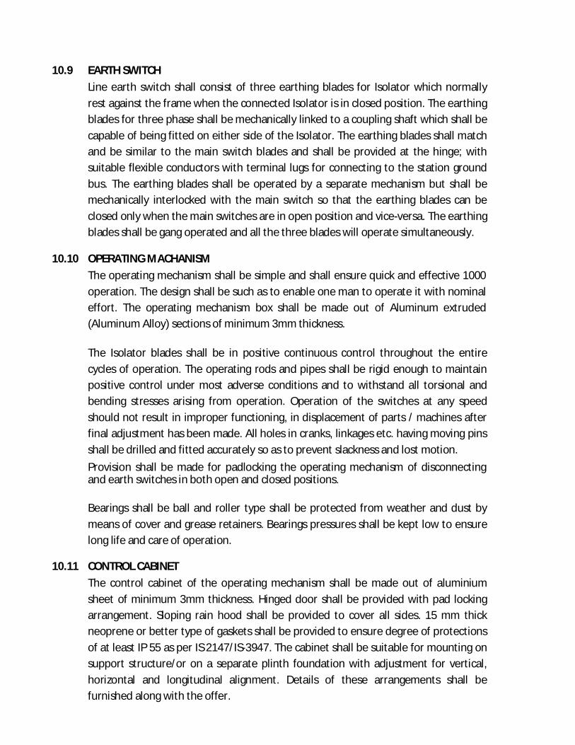
10.9 EARTH SWITCH Line earth switch shall consist of three earthing blades for Isolator which normally
rest against the frame when the connected Isolator is in closed position. The earthing blades for three phase shall be mechanically linked to a coupling shaft which shall be capable of being fitted on either side of the Isolator. The earthing blades shall match and be similar to the main switch blades and shall be provided at the hinge; with suitable flexible conductors with terminal lugs for connecting to the station ground bus. The earthing blades shall be operated by a separate mechanism but shall be mechanically interlocked with the main switch so that the earthing blades can be closed only when the main switches are in open position and vice-versa. The earthing blades shall be gang operated and all the three blades will operate simultaneously.
10.10 OPERATING MACHANISM The operating mechanism shall be simple and shall ensure quick and effective 1000 operation. The design shall be such as to enable one man to operate it with nominal effort. The operating mechanism box shall be made out of Aluminum extruded (Aluminum Alloy) sections of minimum 3mm thickness. The Isolator blades shall be in positive continuous control throughout the entire cycles of operation. The operating rods and pipes shall be rigid enough to maintain positive control under most adverse conditions and to withstand all torsional and bending stresses arising from operation. Operation of the switches at any speed should not result in improper functioning, in displacement of parts / machines after final adjustment has been made. All holes in cranks, linkages etc. having moving pins shall be drilled and fitted accurately so as to prevent slackness and lost motion. Provision shall be made for padlocking the operating mechanism of disconnecting and earth switches in both open and closed positions. Bearings shall be ball and roller type shall be protected from weather and dust by means of cover and grease retainers. Bearings pressures shall be kept low to ensure long life and care of operation.
10.11 CONTROL CABINET The control cabinet of the operating mechanism shall be made out of aluminium sheet of minimum 3mm thickness. Hinged door shall be provided with pad locking arrangement. Sloping rain hood shall be provided to cover all sides. 15 mm thick neoprene or better type of gaskets shall be provided to ensure degree of protections of at least IP 55 as per IS 2147/IS-3947. The cabinet shall be suitable for mounting on support structure/or on a separate plinth foundation with adjustment for vertical, horizontal and longitudinal alignment. Details of these arrangements shall be furnished along with the offer.
10.12 POSITION INDICATOR A position indicator to show the isolator is in ON or OFF position to be provided.
10.13 NAME PLATE Isolator, earthing switches and their operating devices shall be provided with name plate. The name plate shall be weather proof and corrosion proof. It shall be mounted in such a position that it shall be visible in the position of normal service and installation. It shall carry the following informations duly engraved or punched on it. Name :OMC Name of manufacturer – Order No. – Manufacturers serial No. – Rated voltage – Rated normal current – Rated short time current (rms) and duration – Weight All components shall be given adequate treatment of climate proofing as per IS:3202 so as to withstand corrosive and severe service conditions. All metal parts not suitable for painting such as structural steel, pipes, rods, levers, linkages, nuts and bolts used in other than current path etc. shall be hot dip galvanized as per IS -2629. Complete details of painting, galvanizing and climate proofing of the equipment shall be furnished in the offer.
10.14. TESTS i) Type Tests Isolators offered, shall be fully type tested as per the relevant standards. The Bidder shall furnish three sets of the following valid type test reports for their different type of offered Isolators along with the offer. The Purchaser reserves the right to demand repetition of some or all the type tests in the presence of purchaser’s representative. For this purpose the Bidder may quote unit rates for carrying out each type test and this will be taken during bid price evaluation, if required. a) Short time withstand & peak withstand current test for Isolator & Earth Switch. b) Power frequency (Dry & Wet), Lightening Impulse dry withstand Test. c) Mechanical endurance Test. d) IP-55 test. During type tests the isolator shall be mounted on its own support structure or equivalent support structure and installed with its own operating mechanism to make the type tests representative. Drawing of equivalent support structure and mounting arrangements shall be furnished for Purchaser‟s approval before conducting the type tests.

The type tests shall be conducted on the isolator along with approved insulators and terminal connectors. Mechanical endurance test shall be conducted on the main switch as well as earth switch of one isolator of each type. ii) ACCEPTANCE AND ROUTINE TEST All acceptance and routine test as stipulated in the relevant standards shall be carried out by the supplier in presence of Purchasers representative.
Mechanical operation test (routine test) shall be conducted on isolator (main switch and earth switch) at the supplier’s works as well as purchasers substation site. Immediately after finalisation of the programme of type / acceptance, routine testing the supplier shall give sufficient advance intimation (clear 20 days advance intimation), along with shop routine test certificates, valid calibration reports from Govt. approved test house for the equipments, instruments to be used during testing for scrutiny by the purchaser to enable him to depute his representative for witnessing the tests. If there will be any discrepancies in the shop routine test certificates and calibration reports furnished by the firm then after settlement of the discrepancies only, purchasers representative will be deputed for witnessing the tests.
Special tests proposed to be conducted (if decided to conduct) as type test on isolators. These special type test charges shall be quoted along with all other type tests as per relevant IEC standard and these charges shall be included in the total bid price. No material shall be dispatched from its point of manufacture unless the material has been satisfactorily inspected and tested. The acceptance of any quantity of the equipment shall in no way relieve the supplier of his responsibility for meeting all the requirements of this specification and shall not prevent subsequent rejection if such equipment are later found to be defective.
10.15 PACKING AND FORWARDING. The equipment shall be packed in crates suitable for vertical / horizontal transport, as the case may be and suitable to withstand handling during transport and Indoor storage during transit. The supplier shall be responsible for any damage to the equipment during transit, due to improper and inadequate packing. The easily damageable material shall be carefully packed and marked with the appropriate caution symbols. Wherever necessary, proper arrangement for lifting, such as lifting hooks etc. shall be provided. Any material found short inside the packing cases shall be supplied by supplier without any extra cost.

Each consignment shall be accompanied by a detailed packing list containing the following information: (a) Name of the consignee.
(b) Details of consignment.
(c) Destination.
(d) Total weight of consignment.
(e) Handling and unpacking instructions.
(f) Bill of material indicating contents of each package. The supplier shall ensure that the bill of material is approved by the purchaser before despatch.
11.0 TECHNICAL REQUIREMENT FOR 11KV CURRENT TRANSFORMERS The Current Transformers under this specification shall conform to the parameters
given below:
Sl. No. Item Specification
11KV 1. Type of CT/ Installation Single phase, dead tank, oil-filled /
Poly Crate hermetically sealed/ Indoor, self-cooled.
2. Type of mounting Pedestal type 3. Suitable for system frequency 50 HZ 5% 4. Rated Voltage (KV rms) 11 5. Nominal System Voltage (KV rms) 11 6. Highest System Voltage (KV rms) 12 7. Current Ratio (A/A) 400-200-1-1A 8. Method of earthing the system where
the current transformers will be installed
Effectively earthed
9. Rated continuous thermal current (A) 120% of rated primary current 10. Acceptable limit of temperature rise
above continuous operation at rated continuous thermal current
500C ambient temperature for
(a) Winding 400C (b) Oil 350C (c) External surface of the core,
metallic parts in contact with or adjacent to, insulation.
400C
11. 1.2/50 micro second lighting impulse withstand voltage (KVP) (dry)
95
12. 1 Minute dry power frequency withstand voltage primary (KV rms)
28
13. 1 Minute dry power frequency withstand voltage secondary (KV rms)
3

14. Minimum creepage distance of porcelain Housing (mm)
350
15. Rated short time withstand current for 3 second duration at all ratios (KA rms)
25
16. Instrument security factor at all ratios for metering core
Not more than 5.0
17. Maximum rated short time thermal current density of the primary winding copper conductor (A/mm2 ) at all ratios
92
18. Application, current ratio, output burden, accuracy class, minimum knee point voltage, secondary winding resistance, maximum excitation current at minimum knee point voltage etc.
Enclosed in separate sheets for each rating of the current Transformers.
19. Type of Core Torroidal type 20. Seismic acceleration 0.15g (Vertical)
0.3g (Horizontal) 21. Accuracy class of standard C.T to be
used during testing towards determination of ratio errors and phase angle errors for metering cores.
0.05 or better.
REQUIREMENT FOR 12KV CURRENT TRANSFOMERS OF RATIO (a) 400 – 200 – 100 A/ 1 – 1 A
No. of
Cores
Core
No.
Current
ratios (A/A)
Output
burden VA
Accuracy
class as per
IS: 2705
Minimum knee point
voltage (Vk) at
all ratios
in volts
Maximum CT
resistance RCT in
ohms at750C at all
ratiosat highest
tap
Maximum
excitation
current at 50% of Vk in mA at
all ratios
Instrument
security factor
Remarks
1 2 3 4 5 6 7 8 9 10
Two 1
400/1 15 0.5 - - - 5 200/1 15 0.5 - - - 5
2 400/1 - PS 300 ≤10 30 - 200/1 - PS 300 ≤10 30 -
11.1 TEST
TYPE TEST The current transformers, offered should have been subjected to the following type tests in an independent NABL approved test laboratory or CPRI or any International

Lab. Accredited Cooperation (ILAC). The bidder shall furnish four sets of type test reports along with the offer for 0.5 accuracy class C.Ts. These tests must not have been conducted earlier than 05(Five) years from the date of opening of the bid. For any change in the design/type already type tested and the design/ type offered against this specification, the purchaser reserves the right to demand repetition of some or all type tests without any extra cost to OMC in the presence of OMC’s representative at the cost of the supplier. Lightning Impulse Voltage Test and High voltage power frequency wet withstand voltage Test. Short time current test Temperature rise test Determination of errors or other characteristics according to the requirements of the appropriate designation and accuracy class as per individual part of IS:2705. Instruments Security Test. IP-55 Test on Secondary Terminal Box Lightning Impulse Test and High Voltage power frequency wet withstand voltage Tests must have been carried out on the same transformers. After the current transformers have been subjected to lightning Impulse Test and High Voltage power frequency set withstand voltage tests, they must have been subjected to all the routine tests as per IS:2705 (part-I to IV).
12.0 TECHNICAL SPECIFICATION FOR 11KV INDOOR VACUUM CIRCUIT BREAKER
12.1 SCOPE This specification covers design, engineering, manufacture, testing, inspection before dispatch, packing, forwarding, transportation, insurance during transit, delivery to site/ stores of 11KV Indoor Vacuum circuit Breaker for use in the Capacitor Banks. All vacuum circuit breakers must be manufactured by ISO 9000 certified Organization and shall have been type tested at CPRI or any Govt. approval laboratory within five years as on the date of bid opening and in satisfactory operation for a period not less than three years. The scope of supply includes the provision of type tests at any of the NABL accredited Laboratory/International Lab. Accredited Cooperation (ILAC) / CPRI within last 5 Years.
The Dimension of Type Tested VCBs can only be accepted.
The scope also includes G.I. supporting structure for the circuit breaker and current and potential transformers, operating mechanism, local/ remote control cabinet,

relay control panel, foundation bolts, all the accessories and auxiliary equipment mandatory spares and special tools for satisfactory installation and operation. The circuit breakers shall conform in all respects to the highest standards of engineering, design, workmanship, this specification and the latest revisions of relevant standards at the time of offer and the purchaser shall have the power to reject any work or materials, which, in his judgment, is not in full accordance therewith.
12.2 STANDARDS Expect where modified by this specification, the circuit breakers and the accessories shall be designed, manufactured and tested in accordance with latest editions of the following standards.
IEC/ISO/BS IS Subject IEC:56
IEC: 62271-100 & 200
High voltage alternating current circuit breakers general requirement.
IEC:694 IS : 12729 Common clauses of high voltage switch-gear and control gearstandards (for voltage exceeding 1000 V).
IEC:60 IS : 9135 High Voltage testing techniques. IEC:427 IS:13516 Method of synthetic testing of HV. A.C circuit
breakers. IEC: 1233 HV. AC. Circuit breakers- inductive load
switching. IEC: 17A/CD:474 HV. AC. Circuit breakers- capacitive
switching. IEC:529 IS: 13947 Degree of protection provided by enclosure. IEC:137 IS: 2099 Insulating bushing for A.C. voltages above
1000V IEC:233 IS : 5621 Hollow insulators for use in electrical
equipment & testing. IEC:273 IS: 5350 Characteristics of indoor and Indoor post
insulators for systems with nominal voltages greater than 1000V.
IEC:815 IS: 13134 Guide for selection of insulators in respect of polluted conditions.
IEC: 34 IS : 996 A.C motors ISO:1460 BS:729 IS:2629 Hot dip galvanizing
IS:2633 Method of testing uniformity of zinc coated articles.
IS: 5 Colour for ready missed paints and enamels IS: 6005 Code of practice for phosphating or iron and
steel. IEC: 227 IS:1554 P.V.C Insulated cables for voltages up to and
including 1100 Volt. IEC:269 IS:13703 Low voltage fuses for voltages not exceeding
1000volt. ISO:800 IS:1300 Phenolic moulding materials.

IS:13118 Guide for uniform marking and identification of conductors and apparatus terminals.
IEC: 185 IS: 2705 Current transformers. IEC: 296 IS: 335 Specification for unused insulating oil for
transformer and switchgear. IEC:186 IS: 3156 Potential transformers.
CBIP Technical Report No. 88 revised July, 1996 read with amendment issued (April, 99, September, 99 and also any other amendment thereafter)
Specification for AC Static Electrical Energy Meter.
This list is not to be considered exhaustive and reference to a particular standard or recommendation in this specification does not relieve the Supplier of the necessity of providing the goods and services complying with other relevant standards or recommendations.
12.3 BASIC TECHNICAL REQUIREMENTS The circuit breakers to be supplied against this specification shall be required to control the transformer incomer & outgoing 11 KV feeders in 33/11KV sub-stations. The circuit breakers shall be suitable for 3 phase 50Hz solidly grounded neutral system and shall have normal current carrying capacity and symmetrical short circuit current breaking capability as mentioned hereunder. The required 11KV Vacuum Circuit Breaker suitable for Indoor installations are to be quoted by Manufacturers only with a valid ISO 9000 certification. The vacuum circuit breakers are required to meet the following basic technical requirements. (Reference standards IEC:62271 - 100 & 200and associated standards listed in this specification.
BASIC TECHNICAL REQUIREMENTS Sl. No Particulars Requirements
1 Service type Indoor 2 No. of Poles 3 3 Nominal system voltage 11KV 4 Highest system voltage 12KV 5 Rated normal current at 500 C
i) For Interrupter 1250A ii) For Outgoing Feeders & Transformer 1250A
6 Rated short circuit breaking current (rms) for 3 Sec 25KA
7 Rated short circuit making current (peak) 62.5KA
8 Rated short time current withstand capability for 3 sec.
25KA(Panel)/25KA (Interrupter)
9. Rated insulation level:
i)One minute power frequency withstand voltage to earth (wet and dry) rms 28KV

ii)Impulse withstand voltage to earth with1.2/50 sec, wave of +ve and –ve polarity(Peak) 75KV
10 First – pole – to clear factor 1.5 11 Rated operating sequence (for auto reclosing) O-0.3 Sec- CO-3 min-CO 12 Maximum break time 3 cycles
13 Rated out of phase breaking current 25% of the symmetrical
short circuit breaking current 14 Maximum pole scatter 10 mili seconds
15 Rated Auxiliary supply for spring charge motor, lamp & heater circuit. 230V A.C
16 Rated supply voltage for trip/close coil 24V D.C 17 Minimum creepage distance (mm) 350 18 Minimum protected creepage distance (mm) 280
The vacuum circuit breaker VCBs complete with all materials and accessories shall be suitable for Indoor installations with vacuum as interrupting media incorporating separate interrupters of 1250 A rating for each phase mounted on single frame. There shall be a common drive mechanism actuating the interrupters, which must work in synchronism. Preference will be on the following make Vacuum Interrupter such as AREVA, ABB, CGL, Megawin& BEL, while selecting the brought out items. No other make will be considered.
It is not the intent to specify completely herein all details of the design and construction of equipments. However, the equipment shall conform in all respects to high standards of engineering, design and workmanship and shall be capable of performing in continuous commercial operation up to the Bidder‟s guarantee in a manner acceptable to the purchaser, who will interpret the meanings of drawings and specifications and shall have the power to reject any work or material which in his judgment is not in accordance therewith. The offered equipment shall be complete with all components necessary for its effective and trouble free operation along with associated equipments, interlocks, protection schemes etc. Such components shall be deemed to be within the scope of supply, irrespective of whether those are specially brought out in this specification and/ or the commercial order or not.
12.4 DESIGN CRITERIA The equipment will be used in high voltage system having characteristics as listed in the specification. The equipment will be installed Indoor in a hot, humid and tropical atmosphere. All equipment, accessories and wiring shall have tropical protection, involving special treatment of metal and insulation against fungus, insects and corrosion. The maximum temperature in any part of the equipment at specified rating shall not exceed the permissible limits as stipulated in the relevant standards. The safety clearances of all live parts of the equipment shall be as per relevant standards.

The equipment shall be capable of withstanding the dynamic and thermal stresses of listed short circuit current without any damage or deterioration.
12.5 CONSTRUCTIONAL FEATURE The circuit breaker shall be triple pole fixed type. The VCB shall be vermin proof and dust tight. The switchgears and Control gears shall be complete with all necessary supporting frame works, Nuts and bolts etc. for securing the same to the floor. The operating mechanism shall operate (close/open) all the three phases simultaneously. The operating mechanism link etc. should be accessible for maintenance. The circuit breakers and its operating mechanism shall be fully interlocked to prevent mal-operation. All the breakers shall be supplied with necessary clamps and connectors suitable for appropriate current ratings. Rigid type bimetallic/ Al. alloy terminal connector of 1250 Amps. The VCB shall have an arrangement for emergency shunt tripping from remote place in addition to arrangement for local, emergency tripping (Mechanical). The VCB shall also have a system to check. The “Trip circuit healthy check”. Necessary trip and closing coils shall be provided for operation of the breakers. The circuit breaker VCB shall be electrically and mechanically trip free under various conditions.
12.6 MAIN CONTACTS The main contacts shall have adequate area and contact pressure for carrying rated continuous and short time current without excessive heating liable to cause pitting and welding. The breakers may be provided with silver plated contacts, If necessary, to meet the requirement of IS:13118/ IEC 61172 – 100 & 200 where higher temperature rise is permitted with silver plated contacts. The quantity of silver shall be such that after carrying out one tenth of total number of operations specified for mechanical endurance tests, there is still continuous layer of silver on contacts.
12.7 NUMBER & TYPE OF SPARE, AUXILIARY CONTACTS/SWITCHES: Adequate number of spare auxiliary switches/ contacts both of normally open & normally close type but not less than four each shall be provided on the circuit breaker for use in the indication and controlling scheme of circuit breakers.
12.8 INTERLOCK All electrical and mechanical interlocks which are necessary for safe and satisfactory operation of the circuit breaker shall be provided.
12.9 OPERATING MECHANISM

Characteristics of Operating mechanism of circuit breaker and associated equipments: Method of operation: The circuit breaker shall be equipped with power operated mechanism to operate all three phases simultaneously using 220/240 V AC Motor operated spring closing mechanism. It shall be electrically and mechanically trip free under various conditions. VCB shall also be provided with hand operated spring charging closing mechanism. Operation counter and mechanically ON- OFF indicator shall be provided.
12.10 PROTECTIVE RELAY & METERS OF CONTROL PANEL Indoor control panels with protective relay and meter shall be provided by the supplier suitable for above breakers. The equipment shall have protection scheme with the following relays: (i) Triple pole IDMTL type combined over current (2Nos) & Earth fault (1No) relay
(Draw out type) Communicable numerical relay of AREVA, ER,CG, ABB or SIEMENS make with supporting Protocol IEC 60870-5-101,60870-5-104 &IEC:61850. Plug setting range of the over current and earth fault relays shall be5% to 250%.
(ii) Over Voltage Relay. (iii) No Voltage / Over Voltage Relay. (iv) Un Balance Protection Relay –VDG 14. (iv) One alarm bell scheme with bell (24V DC).
12.11 METERS: The following meters shall be provided. (i) Volt meter:- 1 No., 0- 15 KV make IMP/AE/ DIP/RISHAV/MECO (Dial type).
(ii) Volt meter selector switch- 1No. Make- Kaycee or any other reputed make.
(iii) 05 watt LED lamp with switch- 1 No.
(iv) Fuses & Links- 1 No.
(v) Test terminal Blocks- Test terminal Block need be provided for testing relays & meters.
(vi) Indication Lamp- Red- Breaker „ON‟ (24V DC LED type) Green Breaker „OFF‟
(vii) Amber- Breaker ‟AUTO TRIP‟ Blue- Spring charge indication. White-Healthy Trip illuminated push bottom switch
12.12 CONTROL CIRCUIT & ANNUNCIATION (i) One TNC Switch (ii) Alarm Bell Accept Push Button (iii) Alarm Bell Reset Push Button (iv) Window Facia

13.0 TECHNICAL SPECIFICATION FOR 11KV LIGHTNING ARRESTOR
13.1 The specification covers the supply, delivery, erection, testing & commissioning of 9
KV, 10KA, Station class heavy duty, gapless, metal (zinc) oxide surge arrestors complete along with clamps, complete fitting and accessories for installation on Indoor type 11 KV switchgear, transmission lines, transformers etc.
13.2 Tests: The Lightning Arrestors shall be type tested and shall be subjected to routine and acceptance test in accordance with IS: 3070.
13.3 The bidder shall submit guaranteed technical particulars along with their bid.
14.0 TECHNICAL SPECIFICATION FOR 11KV RVT
14.1 The Residual Voltage Transformer shall be dry type, 11 KV class, 5 Limb, with three windings i.e. Star/ Star – Open delta. The Primary winding-I in Star, Secondary-I in Star for metering and Secondary-II in Open delta for protection.
14.2 Tests: The residual Voltage Transformer shall be type tested and shall be subjected to routine and acceptance test in accordance with IS: 3156.
14.3 The bidder shall submit guaranteed technical particulars along with their bid.
RVT Sl. No. Item Specification
1 Nominal system voltage 11 KV 2 Voltage ratio 11 KV /110 V-190V 3 Mode o connection Star/Star/Open delta 4 Rated burden 100VA 5 Type Oil Cooled, Indoor 6 Accuracy class 1/3P 7 Type of core 5 limb construction 8 Terminal arrangements H.V side 4 Nos.11 KV bushing
L.V side Terminal Box 9 Insulation level RMS-28 KV Peak 95 KV
15.0 HT HRC FUSES:
15.1 Suitable indoor / Indoor type 11 KV HRC fuses along with the mounting insulators etc. to provide proper protection for the entire installation shall form part of the equipment to be supplied. The rupturing capacity of the fuses shall be 12.5 KA.
16.0 SERIES REACTORS: The series reactor of small size is required to limit the inrush current during switching operation & suppress the harmonic currents. The series reactor shall be aluminum
wound, Indoor type, 50Hz, air cored / Iron Cored, non magnetically shielded or air cooled type and suitable for operation in climatic conditions specified, conforms to IS:5553 (as amended up to date). The reactor shall be natural air cooled coreless type with one bushing each on incoming and outgoing side. The voltage rating of the series reactor’s base insulator shall be nominal system voltage. Series reactors shall be capable of withstanding the specified short circuit currents.
16.1 CONSTRUCTION FEATURE: 0.2% Series reactor per phase per step of capacitor rating for inrush current restriction to be connected on neutral end as per IS: 5553. The rated voltage shall be 12 KV. The reactor shall be dry type single phase reactors mounted on post insulators and designed to carry 130 % of rated current continuously without exceeding the temperature rise & shall be applicable for thermal class of insulation used. The reactor shall be mounted inside outside the capacitor cubicle on Structure.
16.2 TESTS The series reactor shall be type tested and shall be subjected to routine and acceptance test in accordance with IS: 5553. a) Temp. Rise at rated continuous current Test b) Short circuit Test c) Impulse voltage withstand test. d) Measurement of winding resistance e) Measurement of Impedance f) Measurement of Load losses g) Separate source withstand test h) Inter turn O/V. i) Measurement of IR value
The bidder shall submit guaranteed technical particulars a long with their bid.
17.0 CONTROL CABLE The control cable shall conform to IS: 1554 (Part-I) 1976. All control cable shall be of copper and armored type. The bidder shall furnish such cable schedule after finalization of sub-station layout, associated cable connection.
18.0 CAPACITOR CUBICLE 18.1 General Requirement
It shall be free standing Indoor type sheet steel enclosure fabricated from 1.6 mm. thick CRCA sheets. Capacitor cubical shall be mounted on mild steel channel frame and base frame shall be provided with mounting holes for fixing on concrete foundation. All doors and covers shall be designed to avoid ingress of water, moisture, dust etc. and shall be provided with suitable gaskets to achieve IP-55 degree of protection. Covers and doors shall be provided with electrical interlocks to

avoid access to live parts. In case some unauthorized person opens the door or covers, the main incomer breaker should be tripped. Viewing glasses shall be provided to view inside parts like fuses, contactors. CFL type internal panel lighting shall also be provided to have proper view in the night. Capacitor enclosure shall be duly painted with base coat of Epoxy based primer and final coat of polyurethane paint. FRP canopy shall be provided at the top and which projects about 200 mm beyond cubicle on all sides. All LT internal wiring shall be fire retardant cable of 2.5sq.mm. All cable entries shall be from bottom through cable glands of suitable size. HT XLPE cable entry shall be through a cable entry box mounted on cubicle or fixed separately on foundation and coupled to the cubicle. Necessary Danger plate & Name plate etc shall be provided at prominent places. All other necessary fittings and accessories should be provided by manufacturer to ensure safe and smooth operation of the equipment.
18.2 MOUNTING RACK AND ELEVATING The mounting rack shall be hot dip galvanized (HDG) and should be suitable for Indoor installation under moist conditions, as per relevant standards and latest amendments thereof. Mounting racks shall be complete with rack insulators and interstack insulators, wherever required, shall have basic insulation level. The mounting rack shall be of robust design and shall have two earthing terminals. Capacitors, Capacitor Switches, Series Reactor, LA, Isolators, RVT shall also be mounted on structure. Minimum mass of zinc shall be 610 gm/m2.
18.3 BUSBARS AND INTERCONNECTION MATERIALS Suitable bus bar arrangement shall be provided by the supplier and requisite quantity of bus bar material shall be provided for the Bank. All bus bars shall be aluminum flats with minimum cross section of 120 sq. mm. Bus bar connection between bank and RVT shall also be provided.
18.4 ACCESSORIES Each bus bar arrangement shall be provided with the following accessories: 1. Galvanised supports 2. 2 Nos. earthing terminals 3. Clamps and connectors 4. Aluminum bus bar 5. Series reactor 6. APFC Relay Panel 7. Isolator 8. Lightning Arrestor 9. One no. residual voltage transformer 10. One no. 11kv VCB with structure 11. One set of 11kv Current Transformer with structure 12. Rating Plate 13. All other accessories required for erection, assembly and commissioning of the
capacitor Bank. 14. One capacitance meter with each unit
18.5 RATING PLATE
Each unit shall be fitted with a rating plate giving clearly the particulars specified of marking as per standards:
18.6 CLEARANCES All clearances of live parts between phases and phase to earth shall be adequate.
18.7 INSTALLATION AND MAINENANCE INSTRUCTIONS The supplier shall provide 3 sets of detailed instruction manuals and drawings covering all aspects of installation and maintenance of the Capacitor Bank and the associated equipments. Installation shall be carried out by the purchaser/consignee.
18.8 OPERATION OF CAPACITOR BANK a. The capacitors are proposed to be connected in 3 phase, 11 KV, 50 Hz system.
The maximum symmetrical short circuit level on 11 KV system is 18.4 kA for 3 seconds. 1. It is to be specifically noted that 1200KVARcapacitors bank isintendedfor
use at 33/11 kV sub-station.. b. Maximum permissible over voltage shall be as per standards and latest
amendments thereof.
c. Permissible increase in current loading due to any or all of the following shall not exceed 30% of the rated current. 1. Increase voltage. 2. Increased frequency 3. Non sinusoidal voltage
d. The capacitors shall be suitable for operating in temperature category 50º C as
per standards.
19.0 TEST
19.1 TYPE TESTS All the offered equipment shall be fully type tested by the bidder as per relevant standards including the type tests mentioned below. Type test should have been conducted on the similar or higher capacity of equipments for 11 KV or 33 KV class of capacitor bank from recognized test laboratory preferably CPRI; International Lab. Accredited Cooperation (ILAC) or other Govt, test labs within 5 years prior to date of opening of bid. The bidder shall furnish four sets of test reports as per relevant standards for each type of equipment offered along with the bid. The offers received without type tests shall be tested as non responsive rejected.
a. Thermal stability b. Capacitor less tangent measurement at elevated temperature. c. A.C Voltage test between terminal & container. d. Lightening impulse voltage test between terminal and container. e. Short circuit discharge test.
19.2 ACCEPTING TEST All acceptance tests stipulated in relevant standards and including those as mentioned below shall be carried out by the supplier in presence of Purchaser‟s representative. a. Capacitance measurement test. b. Capacitor loss tangent measurement test. c. Voltage test between terminal. d. Voltage test between terminal and container. e. Tests of internal discharges device. f. Sealing test.
The method shall be subject to agreement between the supplier and purchase where it is not specified in the relevant standards. The purchaser reserves the right to carry out any other test(s) of reasonable nature, in addition to above mentioned tests, at work/test house of the supplier or any other recognized / Research Institute to satisfy that the material compiles with the intent of this specification.
20. INSPECTION All Materials after being received at site will be inspected by Inspector(s) nominated by the Odisha Mining Corporation. Materials supplied if found defective, substandard not to the specification or otherwise unsuitable will be rejected and will be intimated to the successful bidder within 3 days from the date of inspection with instruction to collect the defective materials at its own cost and supply the proper materials immediately.However OMC has the discretion to send its representative for inspection of the material in the factory if required, under prior intimation.
23. DRAWINGS & DOCUMENTATION
24.1 The following drawings illustrating the technical details of this capacitor bank shall be
submitted by each bidder. a) General outlines dimensional drawings of all the equipments with all technical
details giving the net weights, ratings & capacity of equipments and quantity. b) Detailed sectional views, showing the general constructional and other relevant
features of various equipments. c) Schematic connection diagrams for complete capacitor banks with associated
switchgear equipment. d) All above drawings in soft copies.
24.2 In the event of an order, the successful bidder shall furnish the following drawings, in
triplicate, in spiral bound volume, for approval. a) General dimensional outline drawings showing front and side elevations and
plan of Capacitor Units, banks, Circuit Breaker, etc. b) Foundation drawings for structure of capacitor bank. c) Elevated G.I. support structure drawings. d) Internal arrangement and connections of capacitor unit. e) Any other relevant drawing required by purchaser. f) Net & shipping weights, quantity of insulating liquid etc.
24.3 Drawings, diagrams, instructions and reports shall be identified by descriptive titles indicating their applications to the equipment offered. All dimensions shall be in metric system.
24.4 All the drawings of individual equipment shall be marked with all Technical details, Guaranteed Technical Particulars, details of manufacturer etc.
24.5 On approval of the drawings, same shall be sent to the successful bidder for manufacturing the equipment.
24.6 All drawing shall conform to International standards organisation (ISO), „A‟ series of drawing sheets/Indian Standards specification IS:656. All dimensions shall be in SI units.
25.0 GENERAL DESIGN
25.1 DESIGN CRITERIA REQUIREMENTS AND CONSTRUCTIONAL DETAILS OF CAPACITOR
(i) Each bank shall be made of 3 phase two groups of star connected (double star) banks. Each star connected bank shall be unearthed, with a floating neutral, but interconnected by a Neutral Protective Current Transformer (NCT) of suitable ratio, to operate protective relays. The NCT secondary current shall be 1A and its ratio decided by design to meet with the protection requirements specified. Series reactors shall be provided on neutral side.
(ii) The protective scheme shall be either by two step current relay arranged as follows:
If the failure of one or more units causes an over voltage of less than 10% tolerable on the other remaining healthy units, then the unbalance current shall cause in the first step to sound an alarm. But if more than the above numbers of units fail causing a voltage rise of more than 10% then the unbalance current shall cause to trip and isolate the capacitor bank instantaneously.
(iii) The per phase and individual star group rating shall be built up by series parallel combination of individual units so as to achieve the desired rating of the bank. The individual capacity ratings shall be as per IS: 13925.
(iv) All parallel units in one series group shall preferably be arranged in different

tiers, that is, one series group shall be duly insulated from one another by post insulators adequate to withstand the voltage that may be impressed and shall be sufficient to withstand even in case of total failure of all the parallel units in a series group. The complete assembly shall also be duly insulated from the earth potential by supporting post insulators.
(v) Although the tolerances in the output rating of each individual unit shall be as per IS: 13925 yet it shall be ensured that in a completely assembled bank, the departures from the nominal rating and within the specified tolerances values shall not cause nuisance alarm or tripping since such alarm or tripping shall be to meet only with the protective requirements specified.
(vi) The tolerances in the output ratings shall not cause departures in the line currents by that value specified in IS: 13925. Besides it shall also be ensured that these unsymmetrical currents shall not cause unsymmetrical voltage rises, whether for short periods or during prolonged operation.
(vii) Individual units shall be designed to meet with the requirements of the permissible overloads as specified as per IS: 13925. Each unit shall also be provided with internal discharge devices complying with the requirements of the IS: 13925 part-I.
(viii) The rated voltage of the NCT shall be 12 kV and 72.5 kV, taking in to consideration the voltage impressed on the NCT due to: a) Voltage due to failure of one or more parallel units in a series bank. b) Voltage impressed on the NCT when all the parallel units in one series bank
fail simultaneously. The bidders shall furnish design calculations along with the bid.
26.0 PACKING & FORWARDING The equipment shall be packed in creates suitable or vertical, horizontal transport as the case may be and suitable to withstand handling during transport and Indoor storage during transit. The supplier shall be responsible for any damage to the equipment during transit, due to improper and inadequate packing. The easily damageable material shall be carefully packed and marked with the appropriate caution symbol. Wherever necessary proper arrangement for lifting such as fitting hooks shall be provided. Any material found short within the packing case(s) shall be supplied immediately by the supplier without any extra cost to purchaser. Each consignment shall be accompanied with a detailed pacing list containing the following information and shall be marked “ PROPERTY OF OMC”
a. Name o f the consignee b. Details of consignment c. Destination d. Total Weight e. Handing and packing instruments. f. Bills of material indicating contents of each package.
In addition to the above the marking on each package shall per relevant standards.
The packing shall be done as per manufactures standards practice ensuring that no
material is damage during transit by Rail/Road.
27.0 MANDATORY SPARES AND TOOLS The bidder shall supply free of cost, one set of special tools/kit required for erection and maintenance with each capacitor bank. One no. of capacitance meter shall also be provided with each capacitor bank.
28.0 INSTALLATION OPERATION AND MAINTAINANCE The supplier shall provide: 1) Necessary manual on installation, operation and maintenance as also the
schedule for the routine testing or check-ups of all the equipments covered by the installation.
2) The bidder shall provide free of service of their engineers for erection , testing & commissioning of Capacitor Banks along with its accessories at various places under OMC.
29.0 GUIDANCE FOR PROCUREMENT
The entire equipment covered under this specification shall be covered as a single package to avoid the problem of mismatching for maintenance etc.
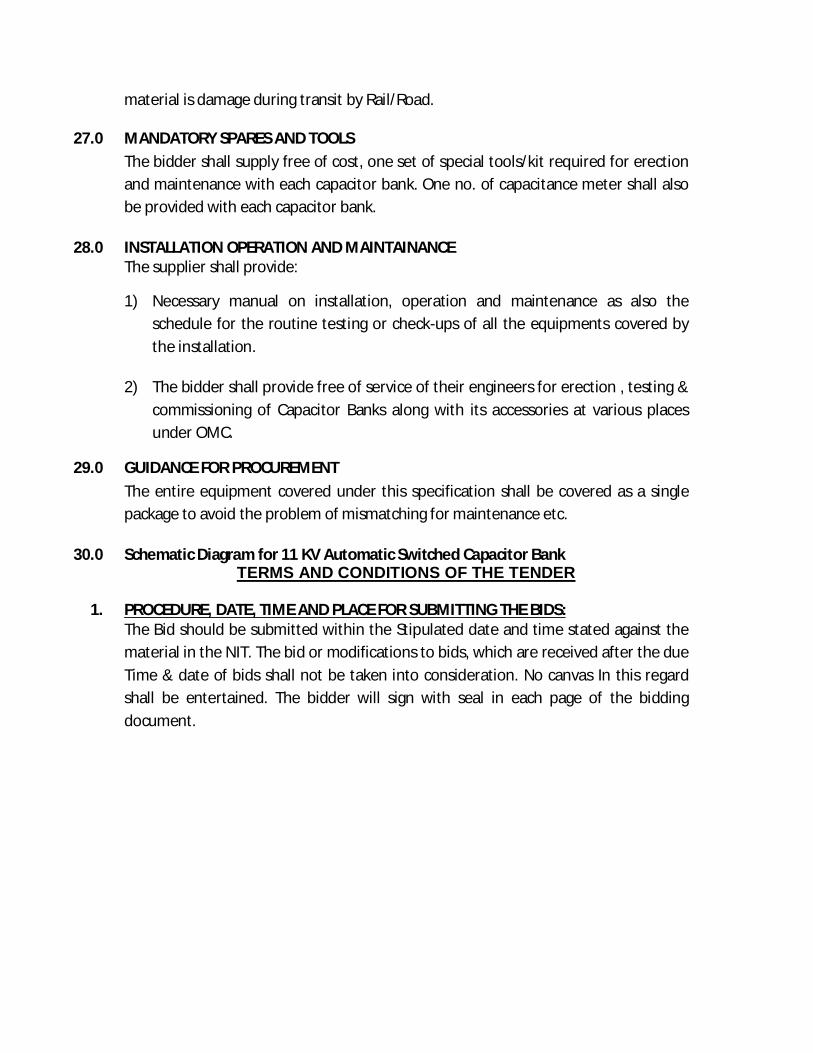
30.0 Schematic Diagram for 11 KV Automatic Switched Capacitor Bank TERMS AND CONDITIONS OF THE TENDER
1. PROCEDURE, DATE, TIME AND PLACE FOR SUBMITTING THE BIDS:
The Bid should be submitted within the Stipulated date and time stated against the material in the NIT. The bid or modifications to bids, which are received after the due Time & date of bids shall not be taken into consideration. No canvas In this regard shall be entertained. The bidder will sign with seal in each page of the bidding document.
2. DATE, TIME AND PLACE OF OPENING OF THE BID:The techno commercial bid shall be opened in presence of the bidders or their authorized representatives in the date and time specified in the NIT in the office of the AGM (Material).The price Bid of the eligible bidders qualified through techno commercial bid shall be opened on a suitable date with prior intimation. The price bid of the disqualified bidders shall not be opened and shall be returned back to the respective bidders unopened.
3. Cost of the tender/bidding document &EMD: The cost of bidding document along with EMD as indicated against the item shall be submitted in shape of Bank draft drawn on any Nationalized/public sector Bank payable at Bhubaneswar in favour of Odisha Mining Corporation Limited. The DD towards the cost of tender paper and EMD should be submitted in the envelope for techno commercial bid. The technical bid without the cost of bidding document and EMD will be summarily rejected. EMD furnished by all unsuccessful tenderers shall be returned after the expiry of tender validity period but not later than 30 days of the award of the contract order without interest, whichever is earlier without any further request from the tenderer(s). If the successful bidder withdraws or amends impairs
or derogates from the tender in any respect within the period of validity of his tender or award of contract, the EMD will stand be forfeited. The EMD of the successful bidder will be returned after successful execution of the work without interest. The
bidder is required to furnish the Bank details for refund of EMD and other payments through RTGS. (a) Exemption of EMD and cost of tender paper may be allowed to the vendor’s
eligible for such exemption by the govt. For such exemption the vendor is to furnish the self-attested documentary evidence along with the bid.
In case if the bidder, who is exempted for depositing cost of tender paper & EMD on the ground of NSIC/SSI holder is selected, they will have to deposit as per the amount mentioned against the item towards security deposit before issue of purchase order & same shall be refunded on successful execution of the work without interest.
4. ELIGIBILITY CRITERIA FOR TENDERERS (i) The documents in support of Sales Tax registration/ TIN/PAN.
(ii) Manufacturer of critical components of the system viz. Capacitor banks, Automatic power factor controller and Vacuum capacitor switches for 11 KV APFC Panel. Valid certificate of the manufacturer/dealer must be attached by the tenderer.
(iii) The bidder has its own service centre available in Odisha.
(iv) The bidder should have experience of execution of HT APFC panel in Govt/PSUs/ Large industry. The certificate of the user in this regard shall also be enclosed.
(v) The bidder should have its own valid HT Contractor License or should have to submit an agreement with the HT contractor who will execute the work on its behalf.
(vi) The bidder shall not have been declared incompetent to participate in such type of bid.
5. SCOPE OF SUPPLY: The successful bidder shall Design &supply the APFC Panel Boards, as per the technical specifications to our Daitari mines ,Keonjhar,Odisha. The bidder shall demonstrate the performance of the APFC Panel board at site to the satisfaction of the OMC Engineer. The materials should be defect free and of good workmanship. The supplier shall prepare drawings for the equipment and get it approved by OMC prior to execution. The supplier shall commission the APFC Panel at site. The required civil work, earthlings, and the cable laying work up to panel board shall be made by OMC. The supplier shall demonstrate the function of each components of the panel board at site. The supplier is to submit the single line diagram, cable termination diagram and other related drawings and diagram at site in three copy. One copy is to be submitted with the bill.

6. Delivery: The delivery period is three months from the date of approval of drawings.
The drawings must be submitted within fifteen days from the date of issue of PO. OMC may negotiate a realistic delivery period with the vendor if the situation warrants so. The supplier shall deliver& installation the materials at the respective sites as mentioned against each item.
7. Warranty: The supplier shall extend warranty for 36 months from the date of
installation& commissioning in respect of proper design, quality, workmanship, correctness in dimension for which same are ordered. The supplier shall be liable to replace defective parts or in whole withina maximum period of 1(one) month on free of cost. No extra charge for transportation shall be paid to the supplier against such replacement.
8. VALIDITY OF THE BID: The Bid shall be valid for (Three months) 90 days from the date of opening of the tender.
9. Price: The price should be quoted in the price Bid format as at Annexure-B. Printed price list of the manufacturer, wherever available, is to be attached with the price bid wherever applicable. The price quoted shall remain firm throughout the validity period. The price comparison shall be made for individual type of APFC Panel.
10. TAXES AND DUTIES (i) The rates quoted by the bidder shall give details of all the taxes, duties &
levies as applicable on the date of bid. In case of variation of taxes/duties/levies and imposition of any new taxes by Govt. notification at a later date, then same shall be reimbursed to the bidder against submission of authentic document toward payment of such taxes by it.
(ii) Service tax as applicable shall be paid extra on the quoted rate. Bills are to be prepared complying to the service tax rule in this regard i.e. as per Rule-4A of the Service Tax Rule.
(iii) Income Tax will be deducted by the OMC as per existing statutory rules. TDS certificate in this effect shall be issued by OMC.
11. Payment Terms: (a) 70% payment shall be released at HO Bhubaneswar, after delivery of materials
at site with due inspection by the representative of OMC and on submission of the bill in duplicate along with test certificate.
(b) 20% payment shall be released after commissioning of the APFC Panel at site. (c) Balance 10% along with EMD shall be released after completion of
warrantyperiod of 36 months. If the agency wants to take the balance 10% value before the warranty period then the agency is required to submit PBG of

equivalent amount valid till completion of warranty period, in OMC format, on any Nationalized Bank.
12. Freight & Insurance: Transportation and transit insurance charges, if any, shall be borne by the Supplier.
13. LIQUIDATED DAMAGE CLAUSE /PENALTY: In case the supplier fails to deliver within the period agreed and stipulated in the purchase order, the penalty will be 0.25% of the basic order value for each 1/10th delay of the original delivery period calculated in number of days.However penalty on this account will not exceed 5% of the basic order value. If the order is not executed within twice the duration of the agreed delivery period then it will be at the discretion of OMC management to cancel the PO./Contract with forfeiture of EMD.
However, OMC shall review the evolving work requirement for the accomplishment of order by the vendor and if required, may extend the time period.
14. Price fall clause: In the event of the supplier found accepting lower prices or supplying at lower rates prior to and after finalisation of rates to any other organization, the said lower rates shall be made applicable to OMC against the PO.
15. Test Certificate:-The supplier shall submit the test certificate wherever required by OMC.
16. Rejection of tender. OMC reserves the right to accept or reject any or all tenders received without any reason thereof.
17. Legal dispute: Incase of any dispute arising out of this Tender it will be subject to the jurisdiction of the courts at Bhubaneswar only in the state of Odisha.
Signature of the Tenderer Addl.General Manager (Mat)
CHECK LIST FOR TECHNOCOMMERCIAL BID
(Following documents are to be enclosed in the techno-commercial bid)
i) Status of the bidder -Manufacturer/Authorised dealer/ Distributor (The copies of valid documents are to be attached. Manufacturership / Dealership/Distributorship certificate)
ii) Attested copies of up to date sales tax/ /TIN / PAN. Certificate
iii) Cost of tender paper a) Draft No.-
b) Date c) Amount
iv) Earnest Money Deposit.(Exemption order/certificate if any) a) Draft No.- b) Date c) Amount
(vii) Tender paper down loaded from the web site, signed on each page and
submitted in the envelope for techno-commercial bid.
(viii) Copy of the Purchase order /Work order for similar type of work if any received by the bidder.
(ix) Forwarding letter as per Annexure-A
SIGNATURE OF THE TENDERER

ANNEXURE-A
SCHEDULE-1 Forwarding letter (To be enclosed in the Techno commercial Bid)
(On the Letter head of the Bidder)
(The bidders is required to indicate in this forwarding letter the details of the documents including DD attached in the bid)
Date: To Addl. General Manager (Materials) Odisha Mining Corporation Ltd. OMC House, Near Secretariat, Bhubaneswar – 751 001, Odisha, India Subject: Proposal towards Design & supply of APFC Panel Boards Being duly authorized to represent and act on behalf of___________________________ (hereinafter referred to as “the Bidder”), and having reviewed and fully understood all of the terms and conditions for submission of the Proposal, the undersigned hereby submits the Proposal for the work under the subject. We confirm that our Proposal is valid for a period of 3 (three) months from Bid Deadline indicated in the tender.
We submit the following Documents in the Bid- 1. Signed Tender Document 2. Cost of Tender paper, EMD 3. APFC panel of specification
OMC and its authorised representatives are hereby specifically authorised to conduct or to make any enquiry or investigations to verify the statements, document and information submitted with this Proposal and / or in connection therewith and to seek clarification from our bankers, financial institutions and clients regarding the same. The undersigned declares that the statements made and the information provided in this Proposal is complete, true and correct in all respects.
Yours faithfully,
(Signature of the Authorised Signatory of Bidder)

ANNEXURE-B (PART-II) PRICE-BID FORMAT
For APFC panel Format for commercial proposal (On the letterhead of the bidder)
(The commercial proposal shall not be conditional or with qualification. In case it is conditional or with qualification, the proposal shall be summarily rejected.)
(Bidder must exercise caution not to fill up the commercial proposal format provided in the tender Documents. The commercial proposal must be submitted
separately in Envelope for price-bid) Date: To Addl. General Manager (Materials) Odisha Mining Corporation Ltd. OMC House, Near Secretariat, Bhubaneswar – 751 001, Odisha, India Subject: Price-bid for supply of APFC Panel Boards Dear Sir,
With reference to the captioned tender, we are pleased to offer our commercial proposal for following.
Sl. No. Item
Landed price in figure in Indian rupees
per each (including taxes, transportation)
Landed price in Indian rupees in words.
per each(including taxes, transportation)
1. 11kv,1200KVAR APFC PANEL WITH ALL OTHER/ RELATED MATERIALS/ ACCESSORIES
2. ERECTION 11kv,1200KVAR APFC PANEL WITH ALL OTHER/ RELATED MATERIALS/ ACCESSORIES
The break-up of the landed price indicating basic price, taxes and duties, transportation, insurance, packing and forwarding etc are stated below.
1. 2. 3.
We have completely read and understood the tender Documents, and this commercial proposal is unconditional and is in line with the requirements of the tender documents.
Yours’ faithfully,
(Signature of the Bidder)


![Medium Voltage Capacitors€¦ · 3 Medium Voltage Capacitors Type MSCE Single Phase Capacitor - Insulation Level 36 kV [50/150] Capacitor without Internal Fuse System Rated Voltage:](https://img.dokumen.tips/doc/110x75/5ead95020ebe1a1107404c5b/medium-voltage-3-medium-voltage-capacitors-type-msce-single-phase-capacitor-insulation.jpg)