Embed Size (px)
Citation preview

REPORT
Ministry of Transportation Nipigon River Bridge Independent Technical Review Nipigon River Bridge Northwestern Region Contract#: 2013-6000
September 2016

1-2 \\s-stc-fs-01\projects\20165982\00_nipigon_analysis\engineering\05.00_design\final report\rpt_nipigon_final_assessment_2016.09.19.docx
CONFIDENTIALITY AND © COPYRIGHT This document is for the sole use of the addressee and Associated Engineering (Ont.) Ltd. The document contains proprietary and confidential information that shall not be reproduced in any manner or disclosed to or discussed with any other parties without the express written permission of Associated Engineering (Ont.) Ltd. Information in this document is to be considered the intellectual property of Associated Engineering (Ont.) Ltd. in accordance with Canadian copyright law. This report was prepared by Associated Engineering (Ont.) Ltd. for the account of Ministry of Transportation Nipigon River Bridge Independent Technical Review. The material in it reflects Associated Engineering (Ont.) Ltd.’s best judgement, in the light of the information available to it, at the time of preparation. Any use which a third party makes of this report, or any reliance on or decisions to be made based on it, are the responsibility of such third parties. Associated Engineering (Ont.) Ltd. accepts no responsibility for damages, if any, suffered by any third party as a result of decisions made or actions based on this report.

Ministry of Transportation - Northwestern Region Report Nipigon River Bridge Nipigon River Bridge Independent Technical Review Contract#: 2013-6000
i \\s-stc-fs-01\projects\20165982\00_nipigon_analysis\engineering\05.00_design\final report\rpt_nipigon_final_assessment_2016.09.19.docx
Executive Summary
This Report was prepared by Associated Engineering (Ont.) Ltd. (AE) for the Ministry of Transportation of
Ontario (MTO) to provide an independent technical review and commentary on the failure of the Nipigon
River Bridge tie-down bearing bolts that occurred on the afternoon of January 10th, 2016.
The bridge is a two-span cable-stayed bridge, designed with a shorter backspan and a longer main span,
creating a permanent uplift tension in the bearings at the west abutment. A similar uplift condition occurs in
many cable-stayed bridges.
On Sunday afternoon January 10, 2016, the Nipigon River Bridge on Highway 11/17, a section of the
TransCanada Highway across northwestern Ontario, became impassable following the complete fracture of
all 40 bolts connecting the tie-down bearing to the main girder bottom flange on the north-west bearing of
the bridge. The temperature on the afternoon of the failure was -16 o Celsius with northerly winds of
approximately 27 km/h.
Immediately upon the failure of the bolts, the unbalanced weight of the spans, acting through the backstay
cables, pulled the north-west end of the bridge deck upwards, coming to rest at approximately 600 mm
above the road level. The center-west bearing did not fail, which limited further damage to the bridge.
The new four-lane bridge is being constructed in two stages, with half of the bridge completed and open to
traffic at the time of the failure. There were no reported injuries to either the public or to bridge workers.
The TransCanada Highway was closed to all traffic for approximately 17 hours while emergency measures
were implemented to bring the bridge back down level with the roadway which allowed a return to single
lane traffic. During the following weeks, two independent temporary tie-down assemblies were installed at
the west abutment to allow two lanes of traffic to safely use the bridge.
Figure 1-1: Nipigon River Bridge, 600mm uplift of north bridge edge at west abutment, January 10th, 2016

Ministry of Transportation - Northwestern Region Report Nipigon River Bridge Nipigon River Bridge Independent Technical Review
Contract#: 2013-6000
ii \\s-stc-fs-01\projects\20165982\00_nipigon_analysis\engineering\05.00_design\final report\rpt_nipigon_final_assessment_2016.09.19.docx
The cause of the tie down failure was a progressive fracture of the 40 (ASTM-A490) bolts connecting the
bearing to the girder flange over the weeks and months prior to the complete fracture of the bolt group.
While the bolt group failure was immediately apparent (as seen in Figure 1-2), the progressive nature of the
bolt fractures and the contributing factors have been identified through examination and testing of the failed
bolts and by the analyses and assessments described in this report.
.
Figure 1-2: Fractured bolts (ASTM A490 bolt - connecting shoe plate to girder flange) and
deformed shoe plate at north-west bearing. Note four lines of failed flange connection bolts.
Figure 1-3: Bearing Nomenclature

Ministry of Transportation - Northwestern Region Report Nipigon River Bridge Nipigon River Bridge Independent Technical Review
Contract#: 2013-6000
iii \\s-stc-fs-01\projects\20165982\00_nipigon_analysis\engineering\05.00_design\final report\rpt_nipigon_final_assessment_2016.09.19.docx
Key findings of this report are:
1. The bolt failure was through a progressive low-cycle fatigue fracture process induced by cyclic
changes in bolt tensions in combination with localized bolt bending. The bolts were loaded in
tension into the plastic range and cycled repeatedly under relatively heavy but highway legal-weight
truck traffic, combined with other demands over the 42-day period following the bridge opening to
traffic. As summarized below, the bolt material met specifications and was not embrittled by
coatings or cold temperatures.
2. The forces and strains in the outer two lines of bolts were increased significantly by flexibility of the
tapered shoe plate and related prying effects between the bearing and the girder flange. In addition
to the flexibility of the shoe plate, yielding and plastic strains also occurred in the shoe plate during
the bolt fracture propagation. Yielding was evident in the permanent bend of the plate following
failure. Both prying effects and plastic behaviour in the shoe plate contributed to increased strains
in the bolts and the progression of the bolt fractures.
3. The stiffness and lack of rotation capacity of the tie-down bearings when acting in uplift lead to
significantly increased bolt forces and strains arising from the deformations imposed by the bridge
superstructure. The resulting force eccentricities both longitudinally and transversely within the
bearing contributed to force redistribution within the bolt group. The bearing system could not
accommodate the specified or in-service demands, in that it neither isolated the bolt groups from
these demands nor provided adequate capacity for the amplification of forces and strains within the
flange-to-bearing bolted connection.
Figure 1-4: Centre-west bearing in place. Bevelled shoe plate is seen
between girder flange and bearing sole plate.

Ministry of Transportation - Northwestern Region Report Nipigon River Bridge Nipigon River Bridge Independent Technical Review
Contract#: 2013-6000
iv \\s-stc-fs-01\projects\20165982\00_nipigon_analysis\engineering\05.00_design\final report\rpt_nipigon_final_assessment_2016.09.19.docx
4. Two types of failure surface propagation were reported by the National Research Council (NRC)
and by Surface Science Western (SSW). One failure surface type had striations progressing from
two sides of a bolt towards an eventual ductile fracture of the centre region, and the other had
striations progressing from one side, also culminating in a final ductile fracture with the bolts under
high tension. These patterns indicate that bending also occurred in many of the bolts. Most bolts
showed clear evidence of low-cycle fatigue cracks. The demands and fracture propagations of the
bolts were influenced by several factors at different stages of the failure progression of the 40-bolt
group. These factors include high tensile strains, cyclic alternating horizontal bending of the bolts in
the outer two lines of bolts, and predominantly one-sided fracture propagation in the inner line of
bolts.
5. The ASTM A490 bolts connecting the girder flanges to the west abutment bearings were not pre-
tensioned (tightened) during bearing installation. Additionally, the bolts supplied were too long,
thread lengths were shorter than standard practice for this length of bolt, and temporary flat
washers were used as an interim measure to allow the nuts and bolt threads to match during
installation. The Canadian Highway Bridge Design Code requires that high-strength bolts in this
type of connection be pre-tensioned (tightened). This would have introduced a large and important
‘clamping’ pressure between the connected plates, which acts to reduce cyclic axial strains in bolts
under service loads. As long as bolt pre-tensions are not exceeded by applied loads, strains in the
bolts would remain nearly constant and low-cycle fatigue failure would not occur. The lack of pre-
tensioning also allowed the shoe plate and girder flange to slip horizontally, thus allowing horizontal
shear forces across the bearings to transfer into the bolts. Polished surfaces on the sides of many
bolts show clearly that sliding occurred. These shear forces would be small if the PTFE was
functioning smoothly as intended, but increase with an increasing friction of damaged PTFE. Our
assessment shows that sufficient bolt bending can be generated from this mechanism even with a
modest increase in PTFE friction. This lack of pre-tension also means that initial forces and strains
in various bolts are neither uniform nor predictable, and may allow for other secondary effects to
occur.
6. Independent testing of the bolts by NRC and SSW concluded that the bolts met the project and
Canadian Highway Bridge Design Code (CHBDC) specifications for materials, strength, ductility
and low-temperature toughness. The bolts met the most stringent low-temperature toughness
requirements required for a bridge located anywhere in Canada. The bolt coating was appropriate
for the ASTM-A490 bolts and did not materially affect the bolt ductility or other properties.
7. The global finite element analysis of the bridge confirmed that the uplift force on the north-west
bearing before the failure occurred was in the order of 1,720 kN for permanent loads only, which
was in general agreement with the design. However, based on our analysis results and design
checks, the west abutment bearings were unable to resist either service or ultimate (factored) uplift
loads and other demands specified on the bridge contract drawings while meeting the design
requirements within the CHBDC. The bearing design did not comply with the requirements of the
contract.

Ministry of Transportation - Northwestern Region Report Nipigon River Bridge Nipigon River Bridge Independent Technical Review
Contract#: 2013-6000
v \\s-stc-fs-01\projects\20165982\00_nipigon_analysis\engineering\05.00_design\final report\rpt_nipigon_final_assessment_2016.09.19.docx
8. Passage of heavy but legal trucks over the bridge, combined with the out-of-parallel bearing
condition arising from the installation methods, would be sufficient to cause permanent
deformations (plastic strains) in bolts from changing uplift reactions and axial forces in the critical
bolts at the north-west bearing. Overload permits issued by MTO indicate that just under ninety
trucks over 60 tonnes (the weight of a code design truck) potentially crossed the bridge. The
passage of these vehicles would be sufficient to contribute to the accumulation of low-cycle fatigue
fractures of the bolts. The number of heavy trucks crossing the bridge is similar in magnitude to the
number of crack propagation cycles seen in the striations on the fracture surface of some of the
bolts.
9. Design-based wind effects (for a relatively short 10-year return period such as typically used for
bridge construction demands) were analyzed and found to increase uplift forces by approximately
10% of the reaction caused by bridge self-weight. This is not sufficient to contribute significantly to
plastic strain accumulation in the bolts. The bridge was unlikely to have experienced winds of this
magnitude prior to the failure. As such, the bearing failure was unlikely to have been influenced
materially by wind effects.
10. Cold temperature effects (cable shortening, deck shortening and deformations) were analyzed and
also found to increase uplift forces by approximately 10%. These increases would have occurred in
combination with truck passage effects, both for uplift and for deformations at the north-west
bearing, and may have accelerated but not materially changed the bridge failure mechanism.
Thermally induced axial deformations in the bridge superstructure would also have affected shear
forces in the northwest bearing as described above, and would have contributed to bolt crack
propagations.
11. The two west abutment bearings supplied had the same design uplift capacities. The north-west
bearing failed, while the centre-west bearing did not. The north-west bearing has higher uplift
demands at this stage of construction than the centre-west bearing, but the latter will have
approximately double the uplift reaction of the north-west bearing in the completed bridge. These
higher loads at the centre girder governed the bearing selection. That the northwest bearing failed
at demands of only half of their maximum design demands illustrates that the bearing assembly’s
capacity, as affected by installation, was substantially deficient. Several conditions at the two
bearings that affected bolt tensions and bolt bending could have been sufficiently different that the
bolt cracking and fracture propagation had not yet occurred at the center bearing. Bolt polish marks
were also observed on the intact bolts of the centre bearing suggesting that it was also experience
bolt bending and was prone to a fracture similar to the north-west bearing failure.

Ministry of Transportation Table of Contents Nipigon River Bridge Independent Technical Review
vi \\s-stc-fs-01\projects\20165982\00_nipigon_analysis\engineering\05.00_design\final report\rpt_nipigon_final_assessment_2016.09.19.docx
Table of Contents
SECTION PAGE NO.
Executive Summary i
Table of Contents vi
List of Tables viii
List of Figures ix
Glossary xii
1 Introduction 1
1.1 Nipigon River Bridge Project – Contract #: 2013-6000 1
1.2 Highway Realignment 1
1.3 Bridge Replacement 1
1.4 Uplift Event & Subsequent Intermediate Remedial Works 1
2 Project Scope 2
3 Project Approach 3
4 Site Visit Observations 4
4.1 Bearing Arrangement 4
4.2 Detailed Structure Inspection – April 2016 4
4.3 Installed Bearing Condition 5
4.4 Flange Connection Bolt Installation 8
4.5 Shoe Plate Observations 11
5 Bolt Investigation Review 14
5.1 National Research Council (NRC) Report Summary 14
5.2 Surface Science Western (SSW) Report 15
5.3 Consideration of photographs taken immediately after the failure 19
5.4 Discussions on Bolt observations 22
5.5 Summary and conclusions 28
6 Review of Documents 30
6.1 Bearing Drawings & Specifications 30
6.2 Bearing Installation and Construction Tolerances 33
6.3 Findings of Bearing Design and Installation Review 37
7 Independent Analysis and West Abutment Bearing Evaluation 38
7.1 Global Model – Phase One 38
7.2 Bearing design evaluation 41

Ministry of Transportation Table of Contents Nipigon River Bridge Independent Technical Review
vii \\s-stc-fs-01\projects\20165982\00_nipigon_analysis\engineering\05.00_design\final report\rpt_nipigon_final_assessment_2016.09.19.docx
7.3 Bearing Failure Analysis 74
8 Discussion 81
8.1 Physical cause of failure 83
8.2 Prying effects 84
8.3 Bearing Deficiencies 84
8.4 Bolt installation 84
8.5 Bearing Installation 85
8.6 Structural demands on bearings 86
8.7 Bolt fracture and contributing factors 87
9 Conclusion 91
10 Closure 92

Ministry of Transportation List of Tables Nipigon River Bridge Independent Technical Review
viii \\s-stc-fs-01\projects\20165982\00_nipigon_analysis\engineering\05.00_design\final report\rpt_nipigon_final_assessment_2016.09.19.docx
List of Tables
PAGE NO.
Table 4-1: Heights measured from the top of the masonry plate to the top of the girder
bottom flange 6
Table 5-1: Updated Bolt Locations 20
Table 7-1: Analysis cases and results summary for design evaluation 52
Table 7-2: Summary of demands for truck passage 75

Ministry of Transportation List of Figures Nipigon River Bridge Independent Technical Review
ix \\s-stc-fs-01\projects\20165982\00_nipigon_analysis\engineering\05.00_design\final report\rpt_nipigon_final_assessment_2016.09.19.docx
List of Figures
PAGE NO.
Figure 1-1: Nipigon River Bridge, 600mm uplift of north bridge edge at west abutment,
January 10th, 2016 i
Figure 1-2: Fractured bolts (ASTM A490 bolt - connecting shoe plate to girder flange) and
deformed shoe plate at north-west bearing. Note four lines of failed flange
connection bolts. ii
Figure 1-3: Bearing Nomenclature ii
Figure 1-4: Centre-west bearing in place. Bevelled shoe plate is seen between girder flange
and bearing sole plate. iii
Figure 4-1: Bearing Nomenclature 4
Figure 4-2: Construction photo of bearing installation showing the shoe plate bolted to the
girder flange 5
Figure 4-3: Measurements taken at the north-west bearing to establish variations in the
alignment 6
Figure 4-4: Plan view schematic of the bearings with measured vertical variations. A
negative value (-) is down, and a positive value (+) is up. 7
Figure 4-5: Distorted PTFE at the southwest corner of the north-west bearing. These photos
were taken of the unloaded bearing after failure. 8
Figure 4-6: Eccentric force application on the bolt as a result of the use of flat washers 9
Figure 4-7: Photo of the Flange Connection Bolts During Construction 10
Figure 4-8: Note the markings on the centre-west bearing connection bolts. Close up of
markings in the insert and general view of the connection bolts. 11
Figure 4-9: Measurements of the permanent northwest bearing shoe plate deformations
(view from underside). AE measurements are shown in red. 12
Figure 4-10: Load path of an applied uplift force showing an exaggerated shoe plate
deformation 13
Figure 5-1: Bolts allocated to the testing laboratories 17
Figure 5-2: Bolt fracture surface types 18
Figure 5-3: Top View of bolt fracture surfaces at the north-west bearing immediately after
failure on January 10, 2016 with information on the fracture surfaces and a
sketch of the dimension of the shoe plate below 21
Figure 5-4: The exaggerated deflected shape of the shoe plate and the girder bottom flange
when subjected to an uplift load 23
Figure 5-5: The observed permanent deformation of the shoe plate immediately after the
failure of the bearing 23
Figure 5-6: Top half of bolt 20/I 24
Figure 5-7: Bottom portion of bolt 20/I 24
Figure 5-8: Bolt 40/EE failed at the head 24

Ministry of Transportation List of Figures Nipigon River Bridge Independent Technical Review
x \\s-stc-fs-01\projects\20165982\00_nipigon_analysis\engineering\05.00_design\final report\rpt_nipigon_final_assessment_2016.09.19.docx
Figure 5-9: Bottom portion of bolt 19/NN 24
Figure 5-10: Top portion of bolt 11/HH 24
Figure 5-11: Bottom half of bolt 10 24
Figure 5-12: Bolts taken from the CW bearing 24
Figure 5-13: Bolt 39 from the CW bearing 24
Figure 5-14: NW quadrant in the foreground and NE quadrant in the background 27
Figure 5-15:SW quadrant in the foreground and SE quadrant in the background 27
Figure 5-16: NE quadrant. North most line of bolt in the NE quadrant 27
Figure 5-17: SE quadrant in the background and 2 bolts from the SW quadrant 27
Figure 6-1: Shaded and labeled excerpts from contract drawing 218-1-R2 30
Figure 6-2: Shoe Plate Detail – Contract Drawings 31
Figure 6-3: Shaded and labeled detail of guide bars from fabrication drawings 33
Figure 7-1: Global Phase One bridge model 38
Figure 7-2: Temporary counter weight on deck at west abutment / resulting bearing
reactions 40
Figure 7-3: West abutment bearing performance requirements - contract drawing 218-B-R1 42
Figure 7-4: West Abutment Bearing Design – Bearing Supplier 43
Figure 7-5: Midas model views of west abutment bearing (plate 3D and 2D) 44
Figure 7-6: Modeled frame elements and load application 45
Figure 7-7: Tensile load vs. elongation bolt behaviour (Reference “Guide to Design Criteria
for Bolted and Riveted Joints”, by Kulak, Fisher, and Struik) 46
Figure 7-8: Bearing rotation schematic 49
Figure 7-9: Exaggerated longitudinal girder rotation combined with uplift reaction 50
Figure 7-10: Bearing longitudinal movement 51
Figure 7-11: Flange connection bolt demand summary for design evaluations 53
Figure 7-12: Centered ULS uplift load; 421.3x8=3,370kN load shown, others similar 54
Figure 7-13: Exaggerated deformed shape for centered uplift reaction 54
Figure 7-14: Von Mises stress [MPa] in bearing elements due to 1,900kN uplift 55
Figure 7-15: Bolt tension [kN] due to 1,900kN uplift 56
Figure 7-16: Bolt elongations [mm] due to 1,900kN uplift 57
Figure 7-17: Von Mises stress [MPa] in bearing elements due to 3,370kN uplift 58
Figure 7-18: Centered ULS uplift load of 3,370kN (schematic view) 59
Figure 7-19: Bolt tension [kN] due to 3,370kN uplift 60
Figure 7-20: Bolt elongations [mm] due to 3,370kN uplift 61
Figure 7-21: Von Mises stress [MPa] in bearing elements due to maximum uplift (5035kN) 62
Figure 7-22: Bolt tension [kN] due to maximum uplift (5035kN) 63
Figure 7-23: Bolt elongations [mm] due to 5035kN uplift 64
Figure 7-24: Bearing longitudinal rotation schematic (exaggerated deformation) 65
Figure 7-25: Transverse bearing rotation schematic (exaggerated deformation) 65
Figure 7-26: Bolt elongation [mm] for uplift of 1,900kN and longitudinal rotation of 0.2⁰ 66
Figure 7-27: Bolt tension [kN] for uplift of 1,900kN and longitudinal rotation of 0.2o 67
Figure 7-28: Von Mises stress [MPa] in plates for uplift of 1,900kN and longitudinal rotation
of 0.2o 68
Figure 7-29: Exaggerated deformed shape of uplift and transverse bearing rotation of 0.2o 69
Ministry of Transportation List of Figures Nipigon River Bridge Independent Technical Review
xi \\s-stc-fs-01\projects\20165982\00_nipigon_analysis\engineering\05.00_design\final report\rpt_nipigon_final_assessment_2016.09.19.docx
Figure 7-30: Bolt tension [kN] for uplift of 1,900kN and transverse rotation of 0.2o 69
Figure 7-31: Bolt elongation [mm] for uplift of 1,900kN and transverse rotation of 0.2o 70
Figure 7-32: Von Mises stress [MPa] in plates for uplift of 1,900kN and transverse rotation of
0.2o 71
Figure 7-33: Bolt elongation [mm] for Zf=3,370kN and e=100mm. Note that maximum
elongation is 3.7mm (>3.5mm), indicating bolt failure 72
Figure 7-34: Von Mises stress [MPa] in bearing plates; Zf=3,370kN’ e=100mm; Longitudinal
Rotation =0.8o 73
Figure 7-35: Truck positions for governing north-west bearing demands 75
Figure 7-36: Compressive forces between plates from Phase One dead load from 76
Figure 7-37: Flange Connection Bolt Elongations [mm] 78
Figure 7-38: Results of single truck live load analysis 79

Ministry of Transportation Glossary Nipigon River Bridge Independent Technical Review
xii \\s-stc-fs-01\projects\20165982\00_nipigon_analysis\engineering\05.00_design\final report\rpt_nipigon_final_assessment_2016.09.19.docx
Glossary
A325 bolt Structural bolt produced in accordance with ASTM material specification
A325. This is a commonly used structural bolt.
A490 bolt Structural bolt produced in accordance with ASTM material specification
A490. This bolt has a higher strength, and less ductility, than an A325
bolt.
Abutment Concrete supporting structure between the bridge superstructure and the
foundation.
Addendum An addition or revision required to be made to a contract document by its
author subsequent to its issue.
Anchor bolt Bolts connecting the steel bearing masonry plate to the concrete
abutment.
Articulation The arrangement and details of bearings and joints in a bridge that
accommodate movements. The articulation also affects how forces are
generated or resisted by these movements.
Beach Mark A distinct curved line on a fractured surface that delineates a change in
condition on the crack propagation pattern.
Bearing A support between the bridge girder and concrete abutment. Movements
and rotations are inherent in the regular service of a bridge. The purpose
of a bearing is to support the bridge, while accommodate these
movements without imposing additional stresses on the structure.
Bearing assembly The bearing and its connecting parts above and below.
Cable stay Cable supporting the bridge deck from the bridge tower.
Canadian Standards
Association (CSA)
A not-for-profit organization which develops standards in 57 areas of
specialization. CSA, along with experts from practice and academia,
produced the Canadian Highway Bridge Design Code.
Charpy test A standardized test that determined the amount of energy absorbed by a
material during fracture. This can be used to describe the material’s
ductility.
CHBDC Canadian Highway Bridge Design Code; current version is CAN/CSA-
S6-14. Nipigon River Bridge designed to CAN/CSA-S6-06 (2006) with
supplements.

Ministry of Transportation Glossary Nipigon River Bridge Independent Technical Review
xiii \\s-stc-fs-01\projects\20165982\00_nipigon_analysis\engineering\05.00_design\final report\rpt_nipigon_final_assessment_2016.09.19.docx
Compression A physical force that pushes the ends of an element outwards its centre.
In this context, it generally refers to bolts and bearing surfaces
experiencing a compression force.
Contract Administrator Company or individual responsible for the administration of the contract
on behalf of the MTO.
Contract drawings The bridge design drawings prepared by the Designer for the tendering
and construction of the bridge.
Deformation Physical movements of the bridge elements as a result of imposed
forces. This includes linear movements and rotations.
Degrees of Freedom A direction in which independent motion can occur. These include
translations and rotations.
Designer A PEO-registered professional engineer responsible for the bridge’s
structural design.
Ductility The ability of a solid material to deform beyond its elastic limit while
sustaining load. This also allows the material to absorb energy before
fracturing.
Eccentricity The uneven (not centered) application of a force which causes additional
stresses on a structure or component.
Elastic The portion of a strain or change in shape of a structurally loaded
element that is fully recovered when the load is removed.
Engineer of Record (EoR) See Designer
Fabrication drawings Bearing drawings used for fabrication. Also called working drawings or
shop drawings depending on the contractual function.
Finger joint (expansion
joint)
Joint in the bridge deck of corresponding metal fingers (teeth) with a gap
between them, allowing for the free expansion and contraction of the
bridge due to temperature.
Flange The horizontal top and bottom plates of the girder.
Girder A main structural supporting member of the bridge. The girder supports
the bridge deck, and is in this case supported by cables attached to the
bridge tower. The girder rests directly on the bridge bearing.
Global analysis An analysis of the overall structural behaviour of the bridge. In this
context, it was used to determine the forces and deformation imposed at
the bearing from the bridge in service.

Ministry of Transportation Glossary Nipigon River Bridge Independent Technical Review
xiv \\s-stc-fs-01\projects\20165982\00_nipigon_analysis\engineering\05.00_design\final report\rpt_nipigon_final_assessment_2016.09.19.docx
Issued for Construction
(IFC) documents
Documents issued by the bridge Designers, containing instructions,
dimensions, and bridge components, from which the bridge is
constructed. Also called contract drawings in this context.
Issued for Tender (IFT)
documents
Drawings and specifications issued to potential bidders to allow them to
prepare financial bids to construct the bridge.
Load path The physical path of internal forces through and between structural
elements, from their point of application to the ground.
Local analysis A detailed analysis of one component of a structure. In this context, the
structural analysis of one bridge bearing.
Low-cycle fatigue The progressive crack propagation of a material by the repeated
application of loads that are large enough to cause plastic strain of the
material.
Masonry plate Bearing component. The steel bottom plate of the bearing, which is in
contact with the concrete abutment.
MTO Ministry of Transportation Ontario
Notch toughness In the context of the bolts, the ability of the bolt material to remain ductile
at cold temperatures.
Phase One This bridge is being built in two phases. Phase One includes the north
and central towers, cable planes, girders, and bearings. The two
northern lanes are open to traffic at the conclusion of Phase One, with
one West-bound lane and one East-bound lane. This was the service
condition at the time of the northwest bearing failure.
Phase Two This bridge is being built in two phases. The conclusion of Phase Two
constitutes the final bridge configuration of four traffic lanes.
OPSS Ontario Provincial Standard Specification
Piles Vertical structural elements driven or drilled into the ground that transfer
forces from the bridge to the soil.
Plastic The portion of a strain or change in shape of a structurally loaded
element that is not fully recovered when the load is removed.
Pre-tensioned In this context, high-strength bolts are installed first to a ‘snug tight’
condition, and then are pre-tensioned using impact wrenches to elongate
the bolt to a very high stress, at or near it’s initial yield stress. This
imparts a high clamping pressure to the connected plates.

Ministry of Transportation Glossary Nipigon River Bridge Independent Technical Review
xv \\s-stc-fs-01\projects\20165982\00_nipigon_analysis\engineering\05.00_design\final report\rpt_nipigon_final_assessment_2016.09.19.docx
Prying A phenomenon in bolted construction that describes additional tensile
forces resisted by the bolts as a result of the connected steel plate
deformation.
Pylon See Tower.
Quality Verification
Engineer (QVE)
means an Engineer qualified to provide the quality verification engineer
services specified in the Contract Documents.
Redundancy The existence of more than one structural load path. If a component of
the structure is damaged or removed, another component will transfer
the load.
Rotation The circular movement of an element around a central point, relative to
another element.
Shoe Plate Steel plate between the girder and the bearing. It is bevelled along its
length to account for the slope of the bridge roadway.
Shop Drawings See Fabrication drawings
Sole Plate Bearing component. The steel top plate of the bearing, which is in
contact with the shoe plate.
Staged construction The construction of the bridge in multiple stages (in this case two), to
allow for partial use of the bridge while the remainder is under
construction.
Strain In this context, a relative change in length of a material due to
compression or tension.
Stress A measure of the average internal force per unit area of an element, as a
result of applied external forces. Each material has its own stress limit,
after which point continued application of the external force will result in
permanent deformation of the material.
Substructure The portion of the bridge that supports the superstructure and transfers
the structural loads to the foundation of the bridge.
Superstructure The portion of the bridge between supports that directly receives the
traffic loads. This includes the bridge deck, girders, and in this case
cables.
Tension A physical force that pulls the ends of an element outwards from its
centre, or pulls two elements apart. In this context, it generally refers to
bolts, or cables, experiencing a stretching force.

Ministry of Transportation Glossary Nipigon River Bridge Independent Technical Review
xvi \\s-stc-fs-01\projects\20165982\00_nipigon_analysis\engineering\05.00_design\final report\rpt_nipigon_final_assessment_2016.09.19.docx
Tie-down Bearing A structural bearing that must resist uplift forces in tension, as opposed
to the more common compression bearing.
Tower The main vertical member near the centre of the bridge from which the
cables are supported, which in turn support the bridge deck.
Translation Linear movement of structural elements; up, down, or sideways.
Working drawings See Fabrication drawings.

REPORT
1 \\s-stc-fs-01\projects\20165982\00_nipigon_analysis\engineering\05.00_design\final report\rpt_nipigon_final_assessment_2016.09.19.docx
1 Introduction
1.1 NIPIGON RIVER BRIDGE PROJECT – CONTRACT #: 2013-6000
The Ministry of Transportation tendered Contract 2013-6000 for the replacement of the Nipigon River
Bridge Project on March 6, 2013. This Group “B” project as defined under the Class Environmental
Assessment for Provincial Transportation Facilities (2000) included both the replacement of the existing
structure as well as highway realignment and upgrades. Highway 11/17 is a strategic link in the
TransCanada Highway system and, at the Nipigon River there is no alternate route across Canada. The
primary objective of this project was to improve and renew this critical link for the country. The expected
fixed completion date for this contract was estimated to be July 28, 2017.
1.2 HIGHWAY REALIGNMENT
The highway component of this project included upgrading the existing cross section to four lanes complete
with wider shoulders to enhance traffic operations and safety. The additional tie in to the eastbound
Highway 17 truck climbing lane and complete illumination to the 2 lane transition was included as well.
Critical design issues included, increasing the median width to 3.8m with future provisions for a barrier, a
grade raise of approximately 2.1m across the project site to enhance drainage and staging/constructability
as traffic must be maintained throughout the duration of construction. The bridge is on a tangent section
with constant 2% cross-fall from the road centreline, and a constant 0.8% longitudinal downhill grade
toward the east.
1.3 BRIDGE REPLACEMENT
The centre piece to this contract is the construction of the new Nipigon River Bridge which is a signature
cable stayed structure. The cable stayed structure is being constructed in two phases with the northern half
built in Phase One and the southern half in Phase Two. Phase One has been in operation since November
7, 2015, and carries two lanes of opposing traffic. Phase Two construction is under way, and will be
completed with ongoing traffic service of Phase One lanes. The structure includes 3m shoulders to enhance
safety and provide future expansion capacity of the highway as well enhance deck structure drainage.
1.4 UPLIFT EVENT & SUBSEQUENT INTERMEDIATE REMEDIAL WORKS
On the afternoon of Sunday, January 10, 2016, the Nipigon River Bridge on Highway 11/17, the
TransCanada Highway across northwestern Ontario, became impassable following the complete fracture of
all 40 bolts at the northwest bearing of the bridge. The temperature on the afternoon of the failure was -16 o
with winds of approximately 27 kph to the North (as recorded from Katatota Island weather station). Phase
One of the four-lane bridge had been constructed at the time of failure. Temporary tie-down assemblies
were subsequently installed at the west abutment to allow two lanes of opposing traffic to safely use the
bridge. Two independent tie-down systems were installed to provide redundancy and safety. Permanent
repairs are currently under design development and will be instituted to facilitate continued construction of
the structure’s second stage.

Ministry of Transportation - Northwestern Region Report Nipigon River Bridge Nipigon River Bridge Independent Technical Review Contract#: 2013-6000
2 \\s-stc-fs-01\projects\20165982\00_nipigon_analysis\engineering\05.00_design\final report\rpt_nipigon_final_assessment_2016.09.19.docx
2 Project Scope
The Ministry of Transportation Ontario (MTO) requested the services of Associated Engineering (Ont.) Ltd.
in February 2016 to provide an independent technical opinion of the observed uplift event that occurred on
the Nipigon River Bridge. The scope of this report is outlined below.
AE was retained to:
i. Undertake an independent inspection of the bridge in its current conditions and to inspect the
failed bolts as examined and tested by National Research Council (NRC), Surface Science
Western (SSW), and MTO.
ii. Analyze the bridge using an independent finite element model of the global structure, and
derive demands exerted on the bearing assembly and abutments from the superstructure.
iii. Analyze and evaluate the local bearing assembly utilizing independently verified demands from
the global model.
iv. Determine the causes of failure that resulted in the uplift event based on all available
information provided or developed independently.
All of the documents reviewed by AE were provided by the Ministry through the project filing site, MTO
RAQS MERX, MTO Emails and Emails from the Designer, Contractor and MTO.

Ministry of Transportation - Northwestern Region Report Nipigon River Bridge Nipigon River Bridge Independent Technical Review Contract#: 2013-6000
3 \\s-stc-fs-01\projects\20165982\00_nipigon_analysis\engineering\05.00_design\final report\rpt_nipigon_final_assessment_2016.09.19.docx
3 Project Approach
AE’s approach to evaluating the cause of the uplift event including the following:
Visit the Site to make observations of the existing conditions following the uplift event inspect, the
bridge, and observe general conditions on site.
Review design and construction documents produced by the Engineer, Contractor, Contract
Administration Consultant and MTO.
View, compare and inspect the bolts as tested by the National Research Council (NRC), Surface
Science Western (SSW), and those retained by MTO.
Document and summarize all bolt observations and tests and combine bolt observations and
testing into our failure assessment.
Develop a global finite element model of the bridge based on as-constructed records to determine
and confirm the demands throughout the structure. These results used for component evaluations
and the bearing failure assessment.
Develop local models of the bearing to evaluate the demands placed on various components of the
bearing assembly utilizing both design and erection information from cable stressing records.
Develop and evaluate bearing failure mechanisms in conjunction with observations and
measurements, finite element models, bolt reports, and engineering interpretation.

Ministry of Transportation - Northwestern Region Report Nipigon River Bridge Nipigon River Bridge Independent Technical Review Contract#: 2013-6000
4 \\s-stc-fs-01\projects\20165982\00_nipigon_analysis\engineering\05.00_design\final report\rpt_nipigon_final_assessment_2016.09.19.docx
4 Site Visit Observations
4.1 BEARING ARRANGEMENT
The nomenclature used to describe the bearing components within the site observations, and throughout
the report, is summarized in Figure 4-1.
The bridge bearings consist of a masonry plate anchored to the concrete abutment, disc bearing
transferring compression forces, sole plate, and bevelled shoe plate. The sole plate is bolted to the
bevelled shoe plate, which is bolted to the steel girder bottom flange. Steel guides connect the sole plate
and masonry plates, providing guidance and resisting uplift. Since transverse restraints are provided, the
bearings are not required to transfer transverse load from the superstructure to the abutment.
Due to the asymmetric bridge span arrangement, the west abutment bridge bearings experience tension
(uplift) due to permanent loads, as well as a combination of service level permanent and transitory loads.
By inspection of the bearing arrangement, we note that there is no mechanism provided for in the design of
the bearing to freely accommodate rotation while subjected to uplift.
4.2 DETAILED STRUCTURE INSPECTION – APRIL 2016
As part of AE’s scope, a detailed site investigation was undertaken in April 2016. The detailed inspection
plan and observations are given in Appendix A, together with sketches used to capture measurements on
site.
The site visit included the following tasks:
Figure 4-1: Bearing Nomenclature

Ministry of Transportation - Northwestern Region Report Nipigon River Bridge Nipigon River Bridge Independent Technical Review Contract#: 2013-6000
5 \\s-stc-fs-01\projects\20165982\00_nipigon_analysis\engineering\05.00_design\final report\rpt_nipigon_final_assessment_2016.09.19.docx
A brief inspection of the bridge as a whole, which included the bridge deck, central tower, stay cables
and anchors and substructure foundations.
Close up examination of all of the bearings and adjoining bridge components at both bridge abutments
A study of the shoe plate. Measurements were taken of the deformed shape of the north-west bearing
shoe plate, and compared with the MTO measurements.
A study of the cut-off ends of the bolts at the MTO offices in Thunder Bay which remained in the shoe
plate. The exposed fractured ends of the bolts had been cut off to enable the reinstatement of bridge
deck levels prior to opening the bridge to traffic.
Brief discussion with Ministry representatives on site to better understand procedures followed during
the installation of the bearings.
4.3 INSTALLED BEARING CONDITION
The bearing installation methods are important as they affect the demands on the bearing assembly. A
review of available photographs of the bearing installation indicate that the shoe plate was affixed to the
girder flange and the bearing sole plate slid into position, and connected to the underside of the shoe plate.
(Figure 4-2). The bearing sole plate was set level onto the concrete abutment.
The fixed dimensions of the pre-fabricated shoe plate, and its attachment to the girder flange in this
sequence, introduced dimensional imperfections between the upper and lower portions of the bearing when
it was subsequently connected to the level set masonry plate.
The predicted slope and elevation of the girder on the contract drawings at the time of bearing installation is
based on an idealized condition. Considering the complexities of segmental cable stay bridge construction
and expected dimensional imperfections in the girder bottom flange during manufacturing, the perfect
position of the bearing would need to be accounted for during its installation by adjustments in the field,
either to the shoe plate dimensions or grouting below the bearing in its neutral position. Due to the
Figure 4-2: Construction photo of bearing installation showing the shoe plate bolted to the girder flange

Ministry of Transportation - Northwestern Region Report Nipigon River Bridge Nipigon River Bridge Independent Technical Review Contract#: 2013-6000
6 \\s-stc-fs-01\projects\20165982\00_nipigon_analysis\engineering\05.00_design\final report\rpt_nipigon_final_assessment_2016.09.19.docx
installation sequence used at this bearing, these variations were not accounted for during bearing
construction. Any dimensional variations in slope and elevation would have been imposed on the bearing
assembly.
Measurements of the relative alignment of bearing components were taken on site to gain an understanding
of the installed condition. The following points are relevant considering when the measurements were
taken:
The bearings were disconnected from the deck superstructure at the west abutment
The deck was being held down by temporary holding down devices installed after the bearing failure
We assume that the girder bottom flanges and bearing masonry plate are as they were prior to the
failure when measuring the difference between the four corners of the shoe plates along the girder
bottom flanges
Measurements were taken on all four corners of each installed bearing, from the top of the bottom flange to
the top of the masonry plate. See Figure 4-3 and Table 4-1.
Figure 4-3: Measurements taken at the north-west bearing to establish variations in the alignment
Table 4-1: Heights measured from the top of the masonry plate to the top of the girder bottom flange

Ministry of Transportation - Northwestern Region Report Nipigon River Bridge Nipigon River Bridge Independent Technical Review Contract#: 2013-6000
7 \\s-stc-fs-01\projects\20165982\00_nipigon_analysis\engineering\05.00_design\final report\rpt_nipigon_final_assessment_2016.09.19.docx
This translates to measured vertical variations along the length of the shoe plate and across the width of the
bottom flange at each of the four abutment bearings as shown in Figure 4-4. Since the measurements were
taken after the failure, with the temporary tie down system in place bypassing the bearing, all
measurements should have been zero had the bearings been installed in a perfectly neutral position. The
variations indicate the out-of-parallel condition imposed on the bearing during construction.
Figure 4-4: Plan view schematic of the bearings with measured vertical variations. A negative value
(-) is down, and a positive value (+) is up.

Ministry of Transportation - Northwestern Region Report Nipigon River Bridge Nipigon River Bridge Independent Technical Review Contract#: 2013-6000
8 \\s-stc-fs-01\projects\20165982\00_nipigon_analysis\engineering\05.00_design\final report\rpt_nipigon_final_assessment_2016.09.19.docx
The corner with the largest positive (+) difference would have been the first corner of the sliding path to be
subjected to wear. Based on the measured variations at the north-west bearing, we would expect the PTFE
along the lower sliding surface to experience the highest pressure and to wear first at the southwest corner
of the bearing. This is consistent with our observations of the distorted PTFE in this location, as shown in
Figure 4-5.
Given these measurements and observations of the bearing’s installed condition, we expect that significant
eccentric forces and high local compression stresses to the PTFE would have been imposed on the bearing
from the time of installation. This would have resulted in an uneven force distribution among the flange
connection bolts under an uplift condition, prior to the application of any traffic or climatic loads.
4.4 FLANGE CONNECTION BOLT INSTALLATION
Based on observations made from available bearing installation photographs, and a review of construction
documentation, we note changes made between the flange connection bolt design and the as-installed
condition. This section summarizes these changes and their impacts to the bearing performance.
4.4.1 Bolt Length
The flange connection bolts were erroneously specified to be too long for the north-west and centre-west
bearings. Additional flat washers were installed to accommodate the longer bolts and the elevated threaded
portions.
Figure 4-5: Distorted PTFE at the southwest corner of the north-west bearing. These photos were
taken of the unloaded bearing after failure.

Ministry of Transportation - Northwestern Region Report Nipigon River Bridge Nipigon River Bridge Independent Technical Review Contract#: 2013-6000
9 \\s-stc-fs-01\projects\20165982\00_nipigon_analysis\engineering\05.00_design\final report\rpt_nipigon_final_assessment_2016.09.19.docx
4.4.2 Lack of Bevelled Washers
The contract drawings show bevelled washers for flange connection bolts, to account for the slope of the
girder bottom flange in relation to the bearing sole plate. The bevelled washers were not installed. Instead
flat washers were used.
The installation of the flat washers is not in accordance with the requirements of the CHBDC, which states
that “in the case of ASTM A490 bolts, bevelled washers shall be used to compensate for any lack of
parallelism due to the slope of outer faces.”
The installation of flat washers instead of the specified bevelled washers would have introduced a local
eccentric force to the bolts as a result of bolt tightening or from axial loads from the uplift force in service. A
sketch showing this local force eccentricity is shown in Figure 4-6. At some locations, when considered
together with the local deformations of the shoe plates and the girder bottom flange in uplift, the local force
eccentricity accentuates bending in the bolt.
4.4.3 Bolt Pre-Tension
Pre-tensioning of bolts, by tightening of the nut to a specified level, provides an important clamping force
that affects the connection behaviour. This force must be overcome before bolt deformations are able to
occur. Any tension forces in the service of the connection will not begin to affect the bolt until the pre-
tension level has been reached. Pre-tensioning is especially important for bolted connections on bridges
due to the cyclic nature of the loads. A lack of pre-tension increases the bolt’s potential vulnerability to
fatigue.
Figure 4-6: Eccentric force application on the bolt as a result of the use of flat washers

Ministry of Transportation - Northwestern Region Report Nipigon River Bridge Nipigon River Bridge Independent Technical Review Contract#: 2013-6000
10 \\s-stc-fs-01\projects\20165982\00_nipigon_analysis\engineering\05.00_design\final report\rpt_nipigon_final_assessment_2016.09.19.docx
Available construction correspondence documents indicate that the bolts were not pre-tensioned as
required by the CHBDC and MTO specifications. This requirement is described further in Section 6.
Furthermore, a close-up bolt photo during construction (see Figure 4-7), shows variations in the observed
bolt protrusion above the nut, which are not related to the bevel of the shoe plate.
The variations of bolt protrusion above the nut between the outer and inner lines of bolts (for example
5>3 labeled in Figure 4-7) indicates that, at the time this photo was taken, some outer line bolts may not
have been fully tightened. Since the sole plate had already been slid into position on the abutment, access
to the bolt head would not have been possible, and consequently, difficulties may have been encountered
that prevented further bolt tightening. Measurements of the bolts during our investigation show that some
M22 bolt heads have a minimum dimension of 39.55mm across their corners. Since the recess for the bolt
heads at the underside of the shoe plate are dimensioned as 40mm x 44mm, it is possible that bolt heads
would have slipped in the recess, preventing further tightening.
Immediately after failure of the north-west bearing, many of the bolts at the centre-west bearing needed at
least a quarter turn of the nut to reinstate snug tightness in the bolts (see Figure 4-8). This indicated that
many of the bolts were loose prior to and at the time of failure which could be interpreted that the same
condition existed at the north-west bearing.
The lack of documented pre-tension and observed variations in bolt protrusion indicate that there would
have been a significant variation in the tightness of the flange connection bolts in their installed condition.
This would have contributed to uneven force distribution among bolts, with the tighter bolts initially
experiencing higher load. Other implications are described throughout this report.
Figure 4-7: Photo of the Flange Connection Bolts During Construction

Ministry of Transportation - Northwestern Region Report Nipigon River Bridge Nipigon River Bridge Independent Technical Review Contract#: 2013-6000
11 \\s-stc-fs-01\projects\20165982\00_nipigon_analysis\engineering\05.00_design\final report\rpt_nipigon_final_assessment_2016.09.19.docx
4.5 SHOE PLATE OBSERVATIONS
Permanent deformation of the north-west bearing shoe plate was observed after the failure. (as seen in
Figures 1-2 and 5-5)
MTO provided drawings prepared internally that included detailed information of the measurements of the
permanently deformed shape of the north-west bearing shoe plate. Figure 4-9 shows the drawing and the
measurements (shown in black) of the post-failure deformed shape as prepared by MTO. These
measurements were verified independently during our study of the plate and are given in red. Both sets of
measurements are in agreement, and indicate the gap between the shoe plate bottom face and a level
placed across the shorter dimension of the shoe plate.
Figure 4-8: Note the markings on the centre-west bearing connection bolts. Close up of
markings in the insert and general view of the connection bolts.

Ministry of Transportation - Northwestern Region Report Nipigon River Bridge Nipigon River Bridge Independent Technical Review Contract#: 2013-6000
12 \\s-stc-fs-01\projects\20165982\00_nipigon_analysis\engineering\05.00_design\final report\rpt_nipigon_final_assessment_2016.09.19.docx
The following is noted from the shoe plate measurements:
The permanent deformations observed in the plate provides evidence of yielding of the shoe plate
Figure 4-9: Measurements of the permanent northwest bearing shoe plate deformations
(view from underside). AE measurements are shown in red.

Ministry of Transportation - Northwestern Region Report Nipigon River Bridge Nipigon River Bridge Independent Technical Review Contract#: 2013-6000
13 \\s-stc-fs-01\projects\20165982\00_nipigon_analysis\engineering\05.00_design\final report\rpt_nipigon_final_assessment_2016.09.19.docx
The maximum deformation of the shoe plate occurs at its thinnest edge and is equal to 7.5 mm. The
maximum deformation along the thicker edge of the shoe plate is 5.7 mm. This difference may be due
to the reduced stiffness of the thinner section of the plate.
The point of maximum deformation is located just to the left of the plate’s centre. This could indicate
that the bolts in the inner line in the northeast quadrant were the last bolts to fail. Bolts in the southwest
quadrant, with the least measured plate deformation, may have been the first to fail.
The recesses were measured to be generally 40 mm x 44 mm x 18mm which confirmed the dimensions
given on the fabrications drawings.
The measured diameter of the bolt holes also confirmed the dimension of 25.4mm given on the
fabrication drawing.
Measurements at each plate cross section indicated a single-curvature plastic deformed shape.
The deformed shape of the shoe plate is consistent with the outer line of bolts having higher initial tensions
and likely failing before the inner line. This can be explained by a mechanism called prying, which is shown
schematically in Figure 4-10 below. This sketch shows how the outer line of flange connection bolts would
have been subjected to a higher portion of the uplift force due to the flexibility of the shoe plate and the
placement of the outer line of bolts connecting it to the sole plate.
The permanent deformation of the shoe plate confirms that the design of the shoe plate and bolted
connection arrangement were inadequate for the transfer of service loads in uplift from the girders to the
bearings. This is consistent with the findings of our bearing analysis discussed in further sections of the
report.
Figure 4-10: Load path of an applied uplift force showing an exaggerated shoe plate deformation

Ministry of Transportation - Northwestern Region Report Nipigon River Bridge Nipigon River Bridge Independent Technical Review Contract#: 2013-6000
14 \\s-stc-fs-01\projects\20165982\00_nipigon_analysis\engineering\05.00_design\final report\rpt_nipigon_final_assessment_2016.09.19.docx
5 Bolt Investigation Review
As part of the investigation, an independent in-depth review of the available documentation was
undertaken.
The following Technical Reports were produced from the evaluation of the failed bolts:
1. Evaluation of Failed Nipigon River Bridge Bolts by NRC Construction, National Research Council
Canada (NRC), Ontario Ministry of Transportation in Ottawa
2. Report on the Evaluation of the Bolts provided by MTO by Surface Science Western (SSW) at the
University of Western Ontario
Upon investigation of the failed bearing immediately after it happened it was found that 39 of the 40 bolts
holding the girder to the northwest shoe-plate had failed by fracture in the threaded portion at or near the
nut, while only one had failed at the bolt head.
Not all of the bolts recovered from the site after the bearing failure could be matched and located on the
shoe plate as the nuts were found to be loose on the bridge or had fallen into the snow around the bearing.
The shaft ends of the bolts still contained within the shoe plate, which were still attached to the bearing sole
plate with the matching fracture surfaces, were cut off to allow the reinstatement of the roadway level and
enable the bridge to be re-opened to traffic. These cut off sections of bolts were also not properly marked
such that they could be relocated on the shoe plate.
Photographs were taken of the tops of the lower portion of bolts left behind on the shoe plate immediately
after the failure. These photographs together with detailed close up photographs from the forensic
investigation of the fracture surfaces of the failed bolts were used to match the bolts and relocate them onto
the shoe plate; 29 of the 40 bolts (73%) that failed were relocated on the shoe plate. This is sufficient to
establish the patterns of failure expected to have developed during failure.
Of the total 40 bolts that failed 14 were sent to NRC, 14 to SSW and 12 remained at the St Catherine’s
MTO offices for study by the MTO Bridge Office staff.
5.1 NATIONAL RESEARCH COUNCIL (NRC) REPORT SUMMARY
The National Research Council (NRC) developed a report for the Ministry to evaluate the failed bolts and
outline particular failure modes. The following is a summary of the pertinent conclusions from the NRC
Report:
a. 14 failed bolts from the NW bearing plus 10 intact bolts from the CW bearing were received
from MTO for testing and analysis.
b. Bolts met the chemical composition and mechanical performance requirements of the
standards

Ministry of Transportation - Northwestern Region Report Nipigon River Bridge Nipigon River Bridge Independent Technical Review Contract#: 2013-6000
15 \\s-stc-fs-01\projects\20165982\00_nipigon_analysis\engineering\05.00_design\final report\rpt_nipigon_final_assessment_2016.09.19.docx
c. Cracks were found in the crest and flanks of both the intact and failed bolts, but no evidence
was found that they contributed to the bolt failure. They were likely present at the time of
installation.
d. Cracks that led to the bolt failures initiated at the thread roots
e. Neither bolt composition, bolt mechanical performance nor the coating appeared to be
responsible for the bolt failures
f. Analysis of the fracture surface showed the following:
i.Bolts failed due to low-cycle (ductile) fatigue, with between 50 and 140 cycles occurring
between crack initiation and final fracture. See NRC Report Table 14 on Page 57
ii.Low-cycle fatigue occurs when plastic behaviour predominates during fatigue and is
controlled by changing strain levels instead of stress levels
g. Bolts failed due to experiencing high cyclic loads, which caused fatigue cracks to initiate and
propagate until the individual bolt’s load capacity was exceeded and the final fractures occur
h. As the bolts did not fail simultaneously, it is likely that full extent of the high loads initially
affected some bolts only. Once those failed, the high loads were then transferred to other
bolts until all failed.
5.2 SURFACE SCIENCE WESTERN (SSW) REPORT
Surface Science Western (SSW) at Western University developed a report for the Ministry to evaluate the
failed bolts and outline particular failure modes. The following is a summary of the pertinent conclusions
from the SSW Report:
a. 14 fractured bolts from the NW bearing plus 10 intact bolts from the SW bearing were
delivered by MTO.
b. All bolts satisfy the chemical composition requirements for Type 1 and Type 3 bolts as
specified in ASTM A490-14a.
c. The metal undergoes ductile failure when loaded at temperatures of -20°C to -30°C.
d. Four intact bolts were tested with a 10° wedge under the head and four more with a 1°
tapered washer under the round washer and nut. All met strength requirements of ASTM
A490-14a.
e. The intact bolts fractured under monotonically increasing tensile load. All regions of the
fracture surface, flat or angled, displayed cup-and-cone features characteristic of a ductile
fracture process.
f. Both the intact bolts and the fractured bolts fractured by crack initiation and growth from the
root of the thread nearest to the nut.
The majority of the fractured bolts displayed:
i.predominantly flat regions, comprised of flat and highly cracked features, extending
from the thread root toward the center of the bolt
ii.The central region of the fracture surface usually contained a region with cup-and-cone
features characteristic of a ductile failure process distinctly different than the flat
regions
iii.Where the flat regions were symmetrically opposed about the mid-plane of the bolt
suggested that cracks nucleated on opposite sides of the bolt and grew together as a
result of alternating cyclic tensile loading until final ductile fracture of the central region
occurred

Ministry of Transportation - Northwestern Region Report Nipigon River Bridge Nipigon River Bridge Independent Technical Review Contract#: 2013-6000
16 \\s-stc-fs-01\projects\20165982\00_nipigon_analysis\engineering\05.00_design\final report\rpt_nipigon_final_assessment_2016.09.19.docx
iv. These fracture surface features are consistent with unidirectional cyclic bending
failure (SSW Report: Page F-12)
Figure 5-1 places the bolts tested by NRC and SSW and those allocated to MTO for their own investigation
on the shoe plate and allows the interpretation of the results from the fracture surface analyses for
understanding possible sequences and patterns of failure.
The division of the failed bolts into three portions was done such that both laboratories and the MTO had
sufficient coverage of the shoe plate. Bolt samples from all four quadrants of the shoe plate were allocated
to each of them to enable their own interpretation of the results from their own analyses, but also to ensure
that bolts tested represented all of the key features of the failure of the bearing.
Figure 5-2 summarizes the results of the bolt fracture surface analyses on the shoe plate. Bolts that had
been subjected to fatigue and bending are shown in green, those that had been subjected to fatigue and
tension in white and when torsion was present at the time of crack initiation they are shown on the sketch in
yellow. Presenting the different types of bolt failures in this way was done with the purpose of possibly
revealing patterns of failure of the bolts which may have existed prior to and during the final failure of the
bearing. A discussion of Figures 5-1 and 5-2 is provided in Section 5.4.

Ministry of Transportation - Northwestern Region Report Nipigon River Bridge Nipigon River Bridge Independent Technical Review Contract#: 2013-6000
17 \\s-stc-fs-01\projects\20165982\00_nipigon_analysis\engineering\05.00_design\final report\rpt_nipigon_final_assessment_2016.09.19.docx
The letters were allocated to bolts by MTO, prior to them being sent to the laboratories.
Figure 5-1: Bolts allocated to the testing laboratories

Ministry of Transportation - Northwestern Region Report Nipigon River Bridge Nipigon River Bridge Independent Technical Review Contract#: 2013-6000
18 \\s-stc-fs-01\projects\20165982\00_nipigon_analysis\engineering\05.00_design\final report\rpt_nipigon_final_assessment_2016.09.19.docx
Figure 5-2 shows the type of bolt failures as observed by the laboratories and interpreted for the remaining
bolts.
Fatigue with tension, crack growth from one side only, cyclic tension
o Fatigue with bending, crack growth from two sides, alternating cyclic tension
o Fatigue with tension, crack growth from one side only, cause of crack is torsion,
Confirmed or potential early failure evident on bolt fracture surface after failure
NRC
NRC
NRC
NRC
NRC
NRC
NRC
NRC
NRC
NRC
Figure 5-2: Bolt fracture surface types

Ministry of Transportation - Northwestern Region Report Nipigon River Bridge Nipigon River Bridge Independent Technical Review Contract#: 2013-6000
19 \\s-stc-fs-01\projects\20165982\00_nipigon_analysis\engineering\05.00_design\final report\rpt_nipigon_final_assessment_2016.09.19.docx
5.3 CONSIDERATION OF PHOTOGRAPHS TAKEN IMMEDIATELY AFTER THE FAILURE
A more detailed analysis of the fracture surfaces was done using the photographs taken of the shoe plate
immediately after the failure and prior to the fractured bolts being cut off (see Figure 5-3 below). The
results of the fracture surface analyses from the NRC and SSW reports, together with our own photographs
and interpretation, were summarized and illustrated on Figure 5-3. The background photograph of the four
bearing quadrants were collated by MTO and presented in such a way that they show the whole of the shoe
plate on this figure.
The following is necessary when observing the illustrations and photos in Figure 5-3.
1. Crack initiation is shown as small yellow arrows. They locate the point where the crack propagated
from and the direction the crack propagation followed
2. The purple arrow at bolt 21/H and 23/BB indicate an additional crack which existed on the fracture
surface of these two bolts, but which did not interfere with the fatigue with tension mode of failure
3. When cracks are initiated from opposite sides of the fracture surface of bolts this is shown as two
yellow arrows pointing in opposite directions
4. Lines of four different colours indicate the angle of crack propagation. Note that the yellow arrows
are always perpendicular to these lines
a. The white lines are derived from the NRC report
b. The blue lines are derived and interpreted from the SSW report
c. The green lines are our own interpretation of the untested bolts at St Catherine’s MTO offices
d. The pink lines have been interpreted directly from these and other photos of the bolts after
failure. It was not possible to allocate a bolt to any of these locations.
5. The width of striations and the number of cycles to failure is taken from the NRC report and is given
in yellow
6. The bolts circled in red depict those with confirmed early failure and those circled in red dashed
lines are those with potential early failure
7. The green circular arrows indicate that the bolt has experienced torsional forces at the time of crack
initiation
8. Information is also given on the fracture pattern observed on the bolts in grey
The following table is presented here for completeness. It includes all additions and changes to bolt
allocation on the shoe plate from a previous sketch provided to AE by MTO. The allocation of bolts on
Figure 5-3 has taken these changes into account.

Ministry of Transportation - Northwestern Region Report Nipigon River Bridge Nipigon River Bridge Independent Technical Review Contract#: 2013-6000
20 \\s-stc-fs-01\projects\20165982\00_nipigon_analysis\engineering\05.00_design\final report\rpt_nipigon_final_assessment_2016.09.19.docx
Bolt Locations 1 to 40
Old New
BB - 23
G 23 39
GG - 25
I 4 20
II - 6
J - 9
K 6 -
L - 38
LL - 32
P - 4?
R - 18
T 18 22
W 5 1
X - 8
NN - 19
Table 5-1: Updated Bolt Locations

Ministry of Transportation - Northwestern Region Report Nipigon River Bridge Nipigon River Bridge Independent Technical Review Contract#: 2013-6000
21 \\s-stc-fs-01\projects\20165982\00_nipigon_analysis\engineering\05.00_design\final report\rpt_nipigon_final_assessment_2016.09.19.docx
Figure 5-3: Top View of bolt fracture surfaces at the north-west bearing immediately after failure on January 10, 2016 with information on the fracture surfaces and a sketch of the dimension of the shoe plate below

Ministry of Transportation - Northwestern Region Report Nipigon River Bridge Nipigon River Bridge Independent Technical Review Contract#: 2013-6000
22 \\s-stc-fs-01\projects\20165982\00_nipigon_analysis\engineering\05.00_design\final report\rpt_nipigon_final_assessment_2016.09.19.docx
5.4 DISCUSSIONS ON BOLT OBSERVATIONS
In order to interpret Figure 5-3, it is necessary to consider the following:
The condition of the connection bolts prior to failure.
The effects of a flexible shoe plate on the increase in loads in some of the connection bolts and on the consequential eccentric forces applied to the nut and bolt head in uplift.
Important considerations from the NRC and SSW reports.
5.4.1 Condition of The Connection Bolts Prior to Failure
The bolts were supplied and installed with a number of deficiencies which contributed to the bearing
behaviour as discussed in Section 4.4 of this report. In summary:
1. The installed bolts were too long and therefore needed additional washers. These were not
bevelled as required by the code for the A490 bolts. Additional eccentric forces on the bolts during
tightening or in the uplift condition would have occurred.
2. Bolts were not pre-tensioned as confirmed by construction documentation.
3. The recess provided in the shoe plate could not prevent the bolt heads from slipping during
tightening, which would further hinder the tightening of the bolts once the shoe plate was installed
4. The shoe plate may have separated from the underside of the bottom flange of the girder during
uplift, potentially due to loose bolts and the deflections in the shoe plate before and during the
gradual failure of the bolts.
5. Shearing between plates and “tilting” of the bolts in service may have occurred and could have
resulted in cyclic alternating tensile forces being applied to the bolts. This may have resulted in the
two-sided crack propagation observed on some bolt fracture surfaces.
6. Shearing effects are expected in the longitudinal direction of the bridge and this effect is observed
in the direction of the striations of the bolt fracture surfaces.
The bolts connecting the girder bottom flange to the bearing were significantly impeded from fulfilling their
function as a result of these limitations.
5.4.2 The Effects of a Flexible Shoe Plate
1. The flexibility of the connection between the bearing and the girder was partly due to the chosen
configuration of the shoe plate, the method used to connect it to the girder bottom flange (see
contract drawing A-11) and the method chosen by the bearing manufacturer to connect the bearing
sole plate to the shoe plate (see fabricators drawings sheet 13 of 15).
2. Figure 5-4 shows an exaggerated view of the expected deformation of both the shoe plate and the
girder bottom flange when subjected to an uplift load from the bridge and Figure 5-5 shows the
shape of the shoe plate after failure.

Ministry of Transportation - Northwestern Region Report Nipigon River Bridge Nipigon River Bridge Independent Technical Review Contract#: 2013-6000
23 \\s-stc-fs-01\projects\20165982\00_nipigon_analysis\engineering\05.00_design\final report\rpt_nipigon_final_assessment_2016.09.19.docx
3. The form that the flexible shoe plate takes in uplift due to how it is connected to the girder and sole
plate will cause a redistribution of forces to stiffer areas of the plate and also apply localized
eccentric forces to the bolts. 4. The prying effects transfer the uplift loads to the outer line of bolts which elongate under load and
result in the shoe plate possibly separating from the underside of the bottom flange along. The
implications of these bolt investigations coupled with bearing design and installation, the demands
on the bearing described in section 7, are interpreted in section 8.
Figure 5-4: The exaggerated deflected shape of the shoe plate and
the girder bottom flange when subjected to an uplift load
Figure 5-5: The observed permanent deformation of the shoe plate
immediately after the failure of the bearing

Ministry of Transportation - Northwestern Region Report Nipigon River Bridge Nipigon River Bridge Independent Technical Review Contract#: 2013-6000
24 \\s-stc-fs-01\projects\20165982\00_nipigon_analysis\engineering\05.00_design\final report\rpt_nipigon_final_assessment_2016.09.19.docx
5. The conditions under which slip between the shoe plate and the girder bottom flange when the
bearing is subject to deck translations and rotations could occur are discussed in Sections 8.7, with
evidence supporting this in Section 5.4.3.
The following phots show clear evidence of rub marks on the sides of bolts which provide evidence
of slip between the shoe plate and the girder bottom flange
Figure 5-6: Top half of bolt 20/I
Figure 5-7: Bottom portion of bolt 20/I
Figure 5-8: Bolt 40/EE failed at the head
Figure 5-9: Bottom portion of bolt 19/NN
Figure 5-10: Top portion of bolt 11/HH
Figure 5-11: Bottom half of bolt 10
Figure 5-12: Bolts taken from the CW bearing
Figure 5-13: Bolt 39 from the CW bearing

Ministry of Transportation - Northwestern Region Report Nipigon River Bridge Nipigon River Bridge Independent Technical Review Contract#: 2013-6000
25 \\s-stc-fs-01\projects\20165982\00_nipigon_analysis\engineering\05.00_design\final report\rpt_nipigon_final_assessment_2016.09.19.docx
5.4.3 Interpretation of Figure 5-3
The following are observations taken from the information summarised on Figure 5-3, which presents
various patterns of failures of the connection bolts, with consideration of the arguments presented above.
1. The fatigue cracks propagate predominantly in the longitudinal direction (west-east direction) of the
bridge. The cracks on the fracture surfaces of the bolts are mostly perpendicular (north-south
direction) to the girders. The following are pertinent points:
Evidence
i. The axis of crack propagation is generally closer to the vertical axis than to the
horizontal axis
ii. The direction of propagation of the fatigue cracks and the location where the cracks
have initiated point generally in the longitudinal direction of the bridge
Reasons
i. Bending introduced in the bolts from a possible shearing of the shoe plate in relation
to the girder flange. Movements are likely to be primarily in the longitudinal direction
of the bridge and would have resulted from the movements of the bridge at the
bearing when subjected to traffic, temperature or other effects.
ii. The inability of the bearing to accommodate rotations in all directions, but in this case
particularly in the longitudinal direction would have accentuated the forces in the
connection bolts from the eccentricities generated along the lower slide paths
iii. Bending of the flexible shoe plate under the permanent uplift loads in service.
iv. The axes about which the fatigue cracks propagate will vary between bolts
depending on, but not limited to, the following factors:
Location of the bolts on the shoe plate.
Translations and rotations on the bearing.
The variation in pre-tensioning loads applied to the prior to failure.
The variation in snug tightness that bolts could have been subjected to prior to
failure.
The possibility of self-loosening of the bolts in service.
The effect of the separation of the shoe plate from the bottom flange
The effect of the flat washers.
The constructed out of tolerance of the sole plate in relation to the masonry
plate of the bearing.
The effect of the progressive failure of the bolts on the deformation of the shoe
plate and the girder bottom flange and the gradual redistribution of the uplift
loads to the remaining bolts prior to final failure of all of the bolts.
2. The outer lines of bolts have been predominantly subjected to unidirectional cyclic bending forces
(alternating cyclic tensile loading) when compared to the inner line of bolts which, apart from 2 bolts
in the SW quadrant, have been subjected only to cyclic tensile forces.

Ministry of Transportation - Northwestern Region Report Nipigon River Bridge Nipigon River Bridge Independent Technical Review Contract#: 2013-6000
26 \\s-stc-fs-01\projects\20165982\00_nipigon_analysis\engineering\05.00_design\final report\rpt_nipigon_final_assessment_2016.09.19.docx
Evidence.
i. At least 9 bolts along the outer lines have evidence of fatigue cracks on the fracture
surface having initiated on opposite sides of the bolts shown on the figure as two
opposing yellow arrows
ii. Rub marks on bolt shanks indicate shear movements across bolt lengths. Note in Figure 5-12 that the rub marks were also seen in the centre-west bearing, which had not failed.
Reasons.
i. The prying effects from the transverse bending of the shoe plate and increased loads
in the outer line of bolts.
ii. A separation of the shoe plate from the girder flange will therefore first occur along
the outer line of bolts as these bolts elongate under load.
iii. Shearing between plates, if this does occur, would impose bending effects to the
loaded outer line of bolts.
iv. Prior to the failure of the outer line of bolts the inner line would be essentially
unloaded but could also be subjected to shearing between plates. However, this
would not be transferred through the bolt heads and nuts as would occur along the
loaded outer line of bolts.
v. After the gradual failure of the outer line of bolts, the inner line of bolts would feel the
effects of the uplift loads, translations and rotations from the bridge deck. As portions
of the outer line of bolts fail, prying effects on the shoe plate are reduced causing the
inner line of bolts to predominantly fail as a result of fatigue and tension only.
3. The failure appears to have begun in the SW quadrant of the shoe plate and ending in the NE quadrant or generally on the eastern quadrants of the shoe plate
Evidence
i. 6 of the 10 bolts in the SW quadrant of the shoe plate exhibited either confirmed or
potential early failure from the evidence of corrosion on the fracture surfaces
observed immediately after the bearing failure.
ii. Unique to this quadrant, the fracture surfaces of the majority of the bolts exhibited
alternating cyclic tensile loading.
iii. The permanent deformation of the shoe plate observed after failure is the least in this
quadrant of the shoe plate.
Reasons
i. Our measurements of gaps between the top of the girder bottom flange and the top
of the masonry plate has indicated that the south-west corner of the bearing would
come into contact first during uplift. We measured a 7 mm difference from the
expected designed elevations along the southern guide.
ii. The PTFE was also found along the sliding surfaces of the longitudinal guides to be
more deformed and damaged at the south-west corner of the bearing.
iii. Higher loads were applied to this quadrant in service and we expect that the bolts in
this quadrant would have resisted the majority of the translations and rotations in
uplift from the traffic on the bridge.
4. The propagation of the cracks on the bolts subjected to cyclic tensile loading appear to be directed
towards the central load bearing stiffener.

Ministry of Transportation - Northwestern Region Report Nipigon River Bridge Nipigon River Bridge Independent Technical Review Contract#: 2013-6000
27 \\s-stc-fs-01\projects\20165982\00_nipigon_analysis\engineering\05.00_design\final report\rpt_nipigon_final_assessment_2016.09.19.docx
Evidence
i. The direction of crack propagation on the majority of the bolts that failed with fatigue
and tension only, generally point towards the centre of the shoe plate and at the
central bearing stiffener
ii. This is more pronounced in the east quadrants.
Reasons
i. The alternating longitudinal translations and rotations from the bridge deck results in
fatigue cracks propagating in opposite directions.
ii. Cracks propagate towards the stiffer part of the shoe plate and the girder bottom
flange. The local effects require additional investigation.
5. Steep angled fracture surfaces are primarily located along the inner line of bolts and in particular
along both inner lines in the north-east and south-east quadrants. These appear to be last group of
bolts to have failed.
Evidence
i. Figures 5-14, 5-15, and 5-17 show in the background the inner line of bolts in the
eastern quadrants with steep fracture surfaces.
ii. Measurements taken of the shoe plate after failure show that the section with the
most deformation coincides with the inner line of bolts in the east quadrants
(maximum deflection of 7.2 mm).
Reasons
i. The two inner lines of bolts in the eastern quadrants of the shoe plate are located on
the more flexible portion of the shoe plate and closest to the thinnest edge of the
shoe plate.
Figure 5-14: NW quadrant in the
foreground and NE quadrant in the
background
Figure 5-15:SW quadrant in the
foreground and SE quadrant in the
background
Figure 5-16: NE quadrant. North
most line of bolt in
the NE quadrant
Figure 5-17: SE quadrant in the
background and 2 bolts from the SW
quadrant

Ministry of Transportation - Northwestern Region Report Nipigon River Bridge Nipigon River Bridge Independent Technical Review Contract#: 2013-6000
28 \\s-stc-fs-01\projects\20165982\00_nipigon_analysis\engineering\05.00_design\final report\rpt_nipigon_final_assessment_2016.09.19.docx
ii. These bolts would have been the least loaded during the gradual failure process of
connection bolts and consequently would have been the last bolts to fail.
iii. The inner lines of bolts would have failed as a result of cyclic tensile loading once
prying effects on the shoe plate were reduced.
The weakest link in the bolts was generally the first thread at the underside of the nut. Cracks typically initiated there and sometimes ended at the root of the first thread (the thread run-out)
Evidence i. Both testing laboratories show the initiation of cracks to be located primarily at the
first thread at the nut. Reasons
i. The first thread is closest to the where the load is applied to the nut, forms a crack induced deformity in the bolt and has a reduced cross sectional area when compared to the shank.
5.5 SUMMARY AND CONCLUSIONS
1. The study of the fracture surfaces of the failed bolts confirm the following:
a. Bolts failed due to experiencing high cyclic loads which caused low cycle fatigue cracks to
initiate and propagate until the individual bolt’s load capacity was exceeded and the final
fracture occurs.
b. Some bolts experienced fatigue crack propagation from one side only indicating direct
tension whilst others showed fatigue cracks that propagated from two sides which indicated
bending effects or also referred to as cyclic alternating tensile loading.
c. The existence of corrosion on some of the fracture surface of bolts indicates that bolts
fractures happened gradually and also provided conclusive evidence that some bolts had
already failed before the time of the final bearing failure.
d. The fracture surfaces show evidence of different types of loading, likely caused by the
decrease in the number of bolts taking up the load applied by the girder as the failure
progressed.
2. Locating the connection bolts where they were on the shoe plate during the failure confirms the following:
a. Crack propagation is predominantly in the longitudinal direction of the bridge and likely
influenced by translations and longitudinal rotations of the bridge from heavy vehicles, slip
between the shoe plate and the girder bottom flange and the inability of the bearing and its
connecting components to accommodate these rotations in uplift.
b. The number of permit vehicles which may have crossed over the bridge before the failure is
consistent with the approximate stress cycles to failure observed on the fracture surfaces of
bolts.
c. There exists a clear pattern of failure on the shoe plate when observing the fracture surface
of the bolts.
i. A large proportion of the bolts in the south-west quadrant exhibit either potential or
confirmed early failure of the bolts. This is consistent with the measured
construction tolerances which indicate that this quadrant would have been the most
heavily loaded section of the shoe plate in uplift.

Ministry of Transportation - Northwestern Region Report Nipigon River Bridge Nipigon River Bridge Independent Technical Review Contract#: 2013-6000
29 \\s-stc-fs-01\projects\20165982\00_nipigon_analysis\engineering\05.00_design\final report\rpt_nipigon_final_assessment_2016.09.19.docx
ii. The outer lines of bolts have flat fracture surfaces and a predominance of crack
propagation from both sides of the bolt which is consistent with these lines being
more subject to the prying effects of the shoe plate and the consequential higher
loads.
iii. The inner lines of bolts have steep fracture surfaces and a predominance of crack
propagation from one side only which is consistent with the expected failure of
bolts in direct tension but not subject to the prying effects of the plate. The prying
effects would have been largely removed after the failure of the higher loaded outer
line of bolts.
iv. Bolts with cracks which have propagated from one side only point mostly towards
the centre of the shoe plate, towards the central load bearing stiffener and the
stiffer part of the plate, supports the contribution that the alternating longitudinal
and rotations have on the propagation of cracks in the bolts.
d. The observations on the fracture surfaces support failure of the bearing that likely
originated within the outer line of bolts and ended with a remaining group of inner line bolts.
3. The connection bolts have been loaded beyond their designed limits because:
a. Rotations of the bridge deck applied to the bearing which was not designed to rotate in
uplift.
b. The force in the outer line of bolts more than doubled by the prying action of the flexible
shoe plate.
c. The concentration of uplift loads on the SW quadrant of the shoe plate resulted from
installation procedures and construction tolerances.
d. Loose and/or un-tensioned connection bolts have contributed to un-equal and eccentric
loads applied to individual bolts.
e. Independent lateral shifting of the shoe plate in relation to the girder bottom flange in shear
may have resulted from the presence of loose connection bolts.
4. The pattern of bolt failures observed on the shoe plate supports the following reasons for the failure of the bearing:
a. The inadequacy of the bearing connection details to the shoe plate and to the girder bottom
flange.
b. The inability of the bearing to accommodate rotation.
c. The inability of the bearing to accommodate the construction out-of-parallel.

Ministry of Transportation - Northwestern Region Report Nipigon River Bridge Nipigon River Bridge Independent Technical Review Contract#: 2013-6000
30 \\s-stc-fs-01\projects\20165982\00_nipigon_analysis\engineering\05.00_design\final report\rpt_nipigon_final_assessment_2016.09.19.docx
6 Review of Documents
6.1 BEARING DRAWINGS & SPECIFICATIONS
Our independent evaluation of the bearing failure included the review of contract drawings, bearing
fabrication drawing, and available construction documentation. The purpose of this review was to determine
the intended function and requirements of the bearing and aspects of the details, fabrication and
construction that may have contributed to the failure. The information and discussion in this section is
intended to be factual and from observation, coupled with engineering considerations for the intended
functions of the bearings.
The following documents were found to be most relevant for understanding the bearing design and
installation:
Bridge contract drawing: Bearing Plan and Design Data. Sheet 218-B-R1. Dated 02/13 & Sealed
11/07/13
Bridge contract drawing: Bearing Plan and Design Data. Sheet 218-1-R2. Dated 02/13 & Sealed
11/07/13
Bridge contract drawing: Bearing Plan and Design Data (Lateral Restraint Device). Sheet 218-2-R2.
Dated 02/13 & Sealed 11/07/13
Bearing fabrication drawings by the bearing supplier. Sheets 1 to 15. Revisions 7 and8. Rev 8 was
dated 21/10/15 & sealed as “As-built” details on 24/11/15
Superstructure Erection Manual
The contract drawings, specifically 218-1-R2, contains details of the connection of the bearings to the
girders bottom flange and to the bearing pedestal. Included in these details are the dimension of the shoe
plate, its bolted connection to the girder, and the anchoring system to the pedestal. Shaded and labeled
excerpts from drawing 218-1-R2 are shown in Figure 6-1. The bearing fabrication drawings include details
Figure 6-1: Shaded and labeled excerpts from contract drawing 218-1-R2

Ministry of Transportation - Northwestern Region Report Nipigon River Bridge Nipigon River Bridge Independent Technical Review Contract#: 2013-6000
31 \\s-stc-fs-01\projects\20165982\00_nipigon_analysis\engineering\05.00_design\final report\rpt_nipigon_final_assessment_2016.09.19.docx
of the “rotational bearing” specified on the contract drawings, as well as the shoe plate and its bolted
connection to the girder flange.
Our review of the contract and fabrication drawings produced the following key points:
The shoe plate dimensions in plan and elevation given on the contract drawings have been repeated on
the bearing fabrication drawings. However, fabrication drawings specify the shoe plate as ASTM A36
(yield strength 248MPa), which is a change or deviation from the specified 350W (yield strength
350MPa) grade steel on the contract drawings.
Instead of 8 rows of 4 M22 (7/8”) ASTM A325 flange connection bolts shown on the contract drawings,
10 rows of 4 M22 (7/8”), ASTM A490 bolts are provided on the as-built fabrication drawings.
The contract drawings do not specify the method for connection of the shoe plate to the bearing
assembly. This was left up to the contractor (and consequently the bearing supplier) to determine. The
bearing supplier specified two lines of 12 x 1” connection bolts along the longitudinal edges (parallel to
the girder) for the connection of the shoe plate to the sole plate. The shoe and sole plate dimensions
on the contract drawings provided adequate space for these bolts to be accommodated. The contract
drawings precluded the use of welds in this connection. This arrangement of bolts contributed to the
prying action of the plate on the flange connection bolts, as was described in Section 4.
The contract drawings show bevelled washers on flange connection bolts to account for the slope of the
girder bottom flange in relation to the bearing sole plate. Despite the bearing being specified to be level
as per installation Note 6 on fabrication drawing sheet 1 of 15, bevelled washers were not specified on
Figure 6-2: Shoe Plate Detail – Contract
Drawings

Ministry of Transportation - Northwestern Region Report Nipigon River Bridge Nipigon River Bridge Independent Technical Review Contract#: 2013-6000
32 \\s-stc-fs-01\projects\20165982\00_nipigon_analysis\engineering\05.00_design\final report\rpt_nipigon_final_assessment_2016.09.19.docx
the fabrication drawings. Flat washers were installed on site, as discussed in Section 4.4.2, introducing
an initial local bolt force eccentricity.
The flange connection bolts on the fabrication drawings were also erroneously specified too long for the
north-west and centre-west bearings. Additional flat washers were installed on site to accommodate the
distance needed to the threaded portions of the bolts.
Since the long bolts could not be readily removed once the bearing was installed and in service, level
solid plates were proposed by the bearing supplier as a permanent solution to replace the additional flat
washers. These were not installed at the time of the bearing failure. Bevelled washers would still be
necessary to meet the specifications.
6.1.1 Bearing Design Rotational Requirements
The bearing supplier was responsible for designing the bearing to accommodate the design loads, rotations
and displacements given on the contract drawings. Contract drawings provided design rotations about the
horizontal and vertical axes. Note 14 of drawing 218-B-R1 stated that the rotational bearings shall
accommodate rotation about horizontal axis as indicated on the bearing design table in all directions.
The maximum serviceability limit state (SLS) rotation specified for the north-west bearing about the
horizontal axis is 0.8º. This maximum horizontal design rotation is 1.3º at the ultimate limit state (ULS).
Specifications OPSS 922 and 1203 also include a requirement to accommodate an additional 1.2º of
rotation about the horizontal axis for the ULS. These requirements were not repeated on either the contract
or fabrication drawings.
Based on the function of the bearing, as discussed in Section 4.1, the bearings were not designed to freely
accommodate the specified rotations when subjected to uplift loads. The rotations in either direction would
impose significant unintended demands on the bearing assembly components, despite the uplift loads and
corresponding rotations being clearly laid out on the contract drawings.
6.1.2 Additional Bearing Constraints
A physical limitation to the allowable bearing rotation is the vertical gap above the lower sliding area of the
bearing. Based on the dimensions taken from the fabrication drawings, we have calculated a remaining gap
of 17.6 mm available for rotation in the uplift condition, when the lower PTFE is in contact with the lower
stainless steel plate (see Figure 6-2). This equates to a physical rotation limit of 1º, which is less that the
required ULS design rotation, even without consideration of the additional OPSS requirements.

Ministry of Transportation - Northwestern Region Report Nipigon River Bridge Nipigon River Bridge Independent Technical Review Contract#: 2013-6000
33 \\s-stc-fs-01\projects\20165982\00_nipigon_analysis\engineering\05.00_design\final report\rpt_nipigon_final_assessment_2016.09.19.docx
The bearing appears to have been designed to be primarily in compression, given that the top PTFE was
recessed, a polytron disk was provided that would only have accomodated rotation under bearing
compression, and the side and lower PTFE was unrecessed. OPSS 1203 requires the PTFE to be
recessed by at least ½ of its depth into the upper surface of the masonry plate along the lower sliding
surface to accommodate the continual uplift forces and corresponding compression loads on the PTFE.
As noted on the contract drawings, the north-west bearing would experience tension (uplift) in service for all
load cases (min uplift force of -140 kN and maximum uplift force of -2540 kN) due to the bridge
configuration. The polytron disk would have been unloaded and have no function for forces or rotations
while in uplift. The lower PTFE would remain in (partial) contact with the lower stainless steel at all times in
service.
6.2 BEARING INSTALLATION AND CONSTRUCTION TOLERANCES
A review of the bearing installation procedure was conducted based on available photographs and the
Superstructure Erection Manual. Information from site personnel was not available regarding the bearing
installation at either the west and east abutments.
The pertinent steps of the installation procedure for the west abutment bearings, as specified by the
Erection Engineer, are as follows:
Install girders NG110 and CG110 and all floor beams except the floorbeam at the
centerline of bearing.
Jack girders NG110 and CG110 vertically to the specified elevations.
Figure 6-3: Shaded and labeled detail of guide bars from fabrication drawings

Ministry of Transportation - Northwestern Region Report Nipigon River Bridge Nipigon River Bridge Independent Technical Review Contract#: 2013-6000
34 \\s-stc-fs-01\projects\20165982\00_nipigon_analysis\engineering\05.00_design\final report\rpt_nipigon_final_assessment_2016.09.19.docx
Install the floorbeam and the north permanent lateral restraint at the centerline of bearing.
Slide the bearings into place and install the post-tensioning bars connecting the bearing to
the abutment.
Jack the structure transversely from the shear block to align the girders with the bearings.
Estimated horizontal jacking distances were provided.
Release horizontal jack and transfer the lateral load to the kicker beam assembly, installed
between the shear block and the girders.
Verify alignment of bearing then engage the vertical jacks, remove cribbing under
floorbeam, and then transfer vertical load to the bearings.
Complete the bearing installation by installing the bolts connecting the bearing to the
bottom flange of the girders.
The following photos were taken on October 5 and 14, 2015, when the north-west bearing was installed.
Key points associated with each photograph are provided.
Photo 1. Date: 10/05/2015
A portion of the deck close to the west abutment,
deck segment 110, and the last four stay cables,
cables CC111, NC111, CC110 and NC110, had not
yet been constructed and installed when the
bearings were installed.
The early phases of the north-west bearing
installation at the west abutment can be seen in this
photo.

Ministry of Transportation - Northwestern Region Report Nipigon River Bridge Nipigon River Bridge Independent Technical Review Contract#: 2013-6000
35 \\s-stc-fs-01\projects\20165982\00_nipigon_analysis\engineering\05.00_design\final report\rpt_nipigon_final_assessment_2016.09.19.docx
Photo 2. Date: 10/05/2015
The shoe plate has been installed onto the girder
bottom flange and is not yet connected to the
bearing sole plate, which is being slid into place.
The masonry plate has been installed and already
grouted onto the bearing pedestal. The sole plate
is later slid into place and connected to the shoe
plate after the masonry plate is installed.
As shown in the close-up detail of the bolts, the
varying bolt protrusions between the inner and
outer line of bolts (δ2>δ1), combined with our bolt
measurements indicates uneven bolt tightening.
The installation of the sole plate prevents access to
the connection bolt heads for bolt tightening
purposes from this point onwards.
Photo 3. Date: 10/05/2015
The shoe plate is connected to the girder bottom
flange. The shoe plate to sole plate connection
bolts have been inserted into the sole plate (seen
being installed from the left of the photo).

Ministry of Transportation - Northwestern Region Report Nipigon River Bridge Nipigon River Bridge Independent Technical Review Contract#: 2013-6000
36 \\s-stc-fs-01\projects\20165982\00_nipigon_analysis\engineering\05.00_design\final report\rpt_nipigon_final_assessment_2016.09.19.docx
Photo 4. Date: 10/14/2015
Nine days later, the bearing installation has been
completed. The sole plate is connected to the shoe
plate and the masonry plate anchor bolts are
installed. The floor beam at the bearing has also
been installed. The bearing is now securely in
place and uplift load will be transferred from the
deck to the west abutment through the bearings
after the deck panels are installed and stressing of
the last four stay cables is completed. These
operations would have introduced some
deformations and force effects onto the bearing
assembly.
Photo 5. Date: 10/14/2015
The north-west and centre-west bearings are in
place and last pre-cast deck segment needs to be
constructed and the last four cables installed.
The available construction photos show two clear variances from the specified installation sequence:
The floor beam connected to the centre load bearing stiffener immediately above the bearing was
installed after the bearings were slid into place. It was uncertain how that may have affected the
performance of the bearing in service.
The shoe plate was bolted to the girder flange prior to connection with the bearing. The Erection
Manual installation procedure specifies this as a final step, although it is unclear how this
recommendation would have improved the performance of the bearing.

Ministry of Transportation - Northwestern Region Report Nipigon River Bridge Nipigon River Bridge Independent Technical Review Contract#: 2013-6000
37 \\s-stc-fs-01\projects\20165982\00_nipigon_analysis\engineering\05.00_design\final report\rpt_nipigon_final_assessment_2016.09.19.docx
In accordance with OPSS 922 the construction tolerances defined in 922.07.06 were not achieved. The
elevations with respect to the top of the bearing as previously noted in Chapter 4, and measured on site,
exceed all of the allowable construction tolerances outlined in this specification.
6.3 FINDINGS OF BEARING DESIGN AND INSTALLATION REVIEW
A summary of the key findings from our review is as follows:
1. The shoe plate was manufactured to the dimensions given in the contract drawings without
provisions for field tolerances. For this installation approach to meet installation specifications in the
field, the masonry plates would have had to be installed parallel to the shoe plate rather than level.
2. The fabrication drawings of the shoe plate introduced dimensional variations from the values given
in the contract drawings between the upper and lower portions of the bearings.
3. Any variations in slope (both longitudinal and transverse) or elevation from that given in the contract
drawings introduced between the girder bottom flange and masonry plates from any cause, would
now cause unintended force effects on the bearing assembly and connections.
4. The location where any rotations could be facilitated would be between the sliding surfaces of the
bottom and top longitudinal guides, because the upper and lower portions of the bearing are
disconnected along these sliding surfaces.
Given the rigid bearing sliding surfaces, which were not designed to accommodate deck rotations nor to
accommodate out-of-parallel tolerances, we expect the functioning of the bearing and of its connection bolts
to be significantly impacted in service. These effects are discussed further in Section 8.

Ministry of Transportation - Northwestern Region Report Nipigon River Bridge Nipigon River Bridge Independent Technical Review Contract#: 2013-6000
38 \\s-stc-fs-01\projects\20165982\00_nipigon_analysis\engineering\05.00_design\final report\rpt_nipigon_final_assessment_2016.09.19.docx
7 Independent Analysis and West Abutment Bearing Evaluation
We have conducted independent global and local (bearing assembly) analyses of the Nipigon Bridge to
achieve the following two goals:
1. Evaluate the design and specifications of the west abutment bearings as shown on the contract
drawings.
2. Develop global demands, and local effects on bearing assemblies from the global bridge model,
to help explain the failure of the north bearing on the west abutment.
To achieve our objectives, we created a global finite element model of the bridge, as well as local models of
west bridge bearings. Our models, modeling assumptions, analysis results and conclusions are provided in
this report.
7.1 GLOBAL MODEL – PHASE ONE
An independent global model analysis of the Nipigon Bridge was completed using the commercially
available Midas finite element program. We have modeled the bridge for the first phase of construction was
with the bridge in service as a two-lane structure. Our Midas model of the Nipigon Bridge after Phase One
is shown in Figure 7-1.
Our global bridge analyses focused on the west abutment bearing reactions and deformations. The
objective of our model is to confirm the abutment bearing reaction forces, and in particular uplift reaction on
the north-west bearing after the first phase of construction.
Figure 7-1: Global Phase One bridge model

Ministry of Transportation - Northwestern Region Report Nipigon River Bridge Nipigon River Bridge Independent Technical Review Contract#: 2013-6000
39 \\s-stc-fs-01\projects\20165982\00_nipigon_analysis\engineering\05.00_design\final report\rpt_nipigon_final_assessment_2016.09.19.docx
7.1.1 Applied Loads in Global Model
To determine bearing reactions on the west abutment bearings, we have applied the following loads to our
Phase One model:
Permanent loads:
Phase One of the construction is complete; bridge operates as a two-lane structure.
Barriers are installed on the bridge deck.
Steel weight: 77 kN/m3. We have added a 25% allowance to the calculated weighs of steel
girder and floor beams to account for miscellaneous components such as splice plates,
stiffeners, studs, bolts and anchor plates. In calculating the weight of bridge cables, we
have included a 10% allowance to allow for cable sheeting, spacers and anchor plates.
Reinforced Concrete weight: 25 kN/m3. Calculated weights of concrete components were
compared to the weights shown on the shop drawings prepared by the pre-caster. While
we could normally assume reinforced concrete weight of 24.0 to 24.5 kN/m3, we have
applied the weight of 25 kN/m3.
No overlay on deck at this time.
Cable forces are assumed to be equal to cable lift-off forces provided by the Contractor.
Counter Weight Load: Following the north-west bearing failure, concrete Temporary Concrete
Barriers (TCBs) were placed on the bridge deck to bring the north bridge girder in contact with the
bearing. The weight placed on the deck consisted of (for illustration see Figure 7-2):
9 Barriers on the sidewalk – 220.68 kN
101 Barriers on the Deck – 2476.53 kN
12 Single Blocks on the Deck – 120 kN
16 Single Blocks – 160 kN
Vehicular load: Live load on the bridge was assumed to consist of one CL-625 ONT truck with
GWV of 63,700 kg as confirmed by the vehicle permit information available. As this analysis is
focused on the north-west bearing, we assume that the truck is using the westbound lane, with no
other loads on the bridge. The truck is assumed to travel at highway speed; truck load is increased
by 25% to account for dynamic impact. We understand just less than 90 similar vehicles have
crossed the bridge from the opening to traffic until the bearing failure occurred. Therefore, this
loading is appropriate for a low cycle fatigue analysis.
Wind load on the structure was conducted for the wind load along the bridge (from west to east)
and perpendicular to the bridge; a 1/10-year wind load was applied on the structure. As this load
case was considered to assess the potential effects on the western bearings and whether wind may
have played a role in the bearing failure. We have based our wind analysis on the methodology
described in the bridge code, rather than an in-depth wind study taking into account specifics of the
location and the bridge structure.
Differential Temperature: The thermal inertia of the bridge cables is much smaller than that of the
concrete pylons and deck. Therefore, there will be times when the bridge cables are warmer or

Ministry of Transportation - Northwestern Region Report Nipigon River Bridge Nipigon River Bridge Independent Technical Review Contract#: 2013-6000
40 \\s-stc-fs-01\projects\20165982\00_nipigon_analysis\engineering\05.00_design\final report\rpt_nipigon_final_assessment_2016.09.19.docx
colder than the rest of the structure. If the cables are colder than the structure, the uplift reaction at
the abutment will increase, and conversely uplift reaction will be reduced if the cables are warmer
than the concrete structure. Based on our field measurements, we have made an assumption that
the difference in temperature of cables and concrete structure can be up to 15oC. This is similar to
cable temperature differenced outlined in the Post-Tensioning Institute (PTI) for cable stayed
bridges. This case was also considered to determine the possible role of thermal effects on the
failure.
The weight of ballast on the deck caused the north girder to touch down on the bearing; we therefore know
that the uplift reaction due to permanent load is not greater than the compression reaction due to barrier
weights. The weight was subsequently removed but this information was a valuable control for our
permanent load reaction calculation as a means to confirm behaviour of the model. A sketch showing
barriers on the deck, and a model rendering showing applied loads and resulting west abutment bearing
reactions is shown on Figure 7-2.
7.1.2 Global Analysis Results
Global analysis results are as follows:
Permanent Loads: We have calculated the bearing reaction due to permanent load (including cable
forces) to be equal to:
o -1,719kN (uplift) at the north bearing.
o -1,064kN (uplift) at the centre bearing.
The result for the north bearing compares well with the calculated reaction for the counterweight on
the deck, which is 2,051kN (compression) at the north bearing and 648kN (compression) at the
centre bearing, see Figure7-2 for illustration. The calculated bearing reaction on the north bearing
Figure 7-2: Temporary counter weight on deck at west abutment / resulting bearing reactions

Ministry of Transportation - Northwestern Region Report Nipigon River Bridge Nipigon River Bridge Independent Technical Review Contract#: 2013-6000
41 \\s-stc-fs-01\projects\20165982\00_nipigon_analysis\engineering\05.00_design\final report\rpt_nipigon_final_assessment_2016.09.19.docx
also compares well with the ‘Dead Load (MIN)’ reaction shown on the design drawings, which is
equal to 1,900 kN.
Counter Weight Reactions: Calculated reaction for the counterweight on the deck is equal to:
o 2,051kN (compression) at the north bearing.
o 648kN (compression) at the centre bearing.
See Figure 7-2 for illustration. As stated above, the calculated reaction for the north bearing is
slightly greater than the permanent load uplift, which can be expected since the counterweight was
sufficient to bring the north bearing into compression.
Vehicular Loads: Bearing reaction on the west abutment due to one CL-625 ONT truck on the west-
bound lane bridge deck are as follows:
o At the north bearing: max. uplift = -154kN; max compression = 466kN
o At the centre bearing: max. uplift = -118kN; max compression = 213kN
The above reactions include the dynamic impact of 25%. In addition to maximum bearing reactions,
we have determined the maximum rotation of the north bearing on the west abutment during the
truck crossings. The maximum girder rotation at the north-west bearing caused by the truck is equal
to approximately 0.19o (in longitudinal direction); this reaction corresponds with north-west bearing
compressive reaction of 275kN.
Wind Load: Additional uplift reaction on the north bearing on the west abutment due to wind load is
in the order of -160 kN on the northwest bearing and 80 kN on the centre bearing, combined with a
longitudinal rotation of 0.06o.
Differential Temperature: Additional uplift reaction due to bridge cables being 15oC colder than the
rest of the structure is in the order of -150kN on north bearing of the west abutment, and 230kN on
the center bearing. If the cables are warmer by 15oC, the two uplift reactions will be reduced by the
same amount. This differential temperature was determined utilizing field measurements
undertaken using an infrared thermometer during the site visit outlined in Section 4. It is also noted
that 15oC is well within the anticipated recommendations for cable-deck thermal differential as
outlined by the Post-Tensioning Institute Recommendations for Stay Cable Design, Testing and
Installation publication.
7.2 BEARING DESIGN EVALUATION
7.2.1 West Abutment Bearing Design
We have analyzed the West Abutment bearings as designed for Phase One construction.
While the bridge design drawings do not include a detailed design of the abutment bearings, performance
requirements for the bearings are provided on drawing 218-B-R1, attached to this report. The designer’s
performance requirements for the bearings include minimum compressive and tensile demands, with
coinciding translation and rotation demands about two horizontal axes and the vertical axis. The bearing
performance requirements for Centre and North bearings on the West Abutment, installed in Phase One of
the bridge construction, are shown in Figure 7-3. Bearing detailed and other design requirements were

Ministry of Transportation - Northwestern Region Report Nipigon River Bridge Nipigon River Bridge Independent Technical Review Contract#: 2013-6000
42 \\s-stc-fs-01\projects\20165982\00_nipigon_analysis\engineering\05.00_design\final report\rpt_nipigon_final_assessment_2016.09.19.docx
described previously in Section 6.1. Our design reviews were based on the contract and fabrication
drawings provided.
Note 14 on drawing 218-B-R1 states that the “rotational bearings shall accommodate rotation about
horizontal axis as indicated on the bearing design table in all directions”
The contract drawings also include the design of the bevelled shoe plate and the bolts connecting the shoe
plate to the girder bottom flange. The bevelled shoe plate is specified, on contract drawing 218-1-R2, to be
1000 mm long and 800 wide with thickness varying from 52 to 60 mm, to compensate for girder grade and
provide a level bearing. For illustration see Figure 6-2. The bevelled shoe plate steel grade is specified on
drawing number 218 as grade 350W to CAN/CSA G40.21-M04; with yield strength of Fy = 350 MPa. The
contract drawings show the shoe plate connected to the girder bottom flange with 32-22 (7/8”) bolts,
grade ASTM A325.
Bearing fabrication drawings include: masonry plate, sole plate, compression bearing, bevelled shoe plate,
as well as the bolted connection between sole plate and bevelled shoe plate, and the bolted connection
between bevelled shoe plate and girder flange.
Figure 7-3: West abutment bearing performance requirements - contract drawing 218-B-R1

Ministry of Transportation - Northwestern Region Report Nipigon River Bridge Nipigon River Bridge Independent Technical Review Contract#: 2013-6000
43 \\s-stc-fs-01\projects\20165982\00_nipigon_analysis\engineering\05.00_design\final report\rpt_nipigon_final_assessment_2016.09.19.docx
The detailed design of the bevelled shoe plate and the bolted connection to the girder flange by the bearing
supplier is based on the contract drawings; the size of the bevelled plate is as shown on the contract
drawings (800x1000 plate, thickness varies 52-60mm).
The Bearing Capacity Table shown on the fabrication drawings Sheet 3 of 14, asserts that the bearing
meets the performance requirement specified on contract drawing Sheet 218. Specifically, the Bearing
Capacity Table notes that the bearing meets requirements for:
compressive and uplift capacity,
longitudinal displacement,
the ability to accommodate a ‘service rotation’ of 0.0175rad (1.0o), and
the ability to accommodate a ‘strength rotation’ of 0.0244rad (1.4o).
While the bearing is in compression, the rotation occurs about the Polytron disk supporting the bridge.
However, when the bearing is in tension (uplift), the rigid steel restrainers of the upper and lower blocks are
in contact, separated by a thin sheet of PTFE, and are therefore unable to accommodate rotation about any
horizontal axis. Due to the horizontal clearance between the upper and lower block restrainers, the bearing
is capable of accommodating some rotation about the vertical axis. Neither the contract drawings nor
fabrication drawings specify construction tolerances for bearing placement.
Figure 7-4: West Abutment Bearing Design – Bearing Supplier

Ministry of Transportation - Northwestern Region Report Nipigon River Bridge Nipigon River Bridge Independent Technical Review Contract#: 2013-6000
44 \\s-stc-fs-01\projects\20165982\00_nipigon_analysis\engineering\05.00_design\final report\rpt_nipigon_final_assessment_2016.09.19.docx
7.2.2 West Abutment Bearing Finite Element Model
The objectives of the analysis were to determine the adequacy of the bearing design and explain the North
girder bearing failure. To achieve the objectives, a finite element (FE) model of the west abutment bearing
using Midas Civil analysis software was created. The FE model of the West Abutment Bearing reflects the
bearing design shown on the bridge contract drawings and the bearing fabrication drawings.
The 3D bearing model was built using shell elements to represent the masonry plate, sole plate, shoe plate,
and girder flanges, web and stiffeners (see Figure 7-5). All plates are modeled as linearly elastic. However,
in cases where calculated stresses in plates exceeded yield strength, plastic deformation of the steel was
considered. The bolts were modeled as non-linear frame elements. The modeled bolt non-linearity enabled
the simulation of inelastic deformation of bolts for a more realistic prediction of ultimate bolt failure. The
PTFE contact between lower and upper guide bars was modeled using non-linear frame members; linking
the upper and lower block under compressive load and releasing at tensile load, allowing the upper and
lower guide bars to separate and form a gap.
Figure 7-5: Midas model views of west abutment bearing (plate 3D and 2D)

Ministry of Transportation - Northwestern Region Report Nipigon River Bridge Nipigon River Bridge Independent Technical Review Contract#: 2013-6000
45 \\s-stc-fs-01\projects\20165982\00_nipigon_analysis\engineering\05.00_design\final report\rpt_nipigon_final_assessment_2016.09.19.docx
To realistically determine the distribution of stresses on the plates and bolts, a section of steel plate girder,
with stiffeners was included in the model. For convenience, the girder top flange was restrained along the
girder web line and a tensile (downward) load was applied on the nodes representing the 8 anchors
connecting the masonry plate to the concrete abutment. For illustration of modeled frame elements and
load application, see Figure 7-6.
7.2.2.1 Modeling Assumptions
Modelling assumptions have been included that idealise material properties, fabrication and installation of
components. Specifically, it has been assumed that all the materials conform to specifications, and that all
bolts are installed in a way that maximises the capacity of the bolted connection. The model will allow the
bearing assembly and connected plates to deform and rotate to the degree that they are physically capable,
notwithstanding that the bearing itself is rigid and not designed to rotate freely.
The FE model geometry and section properties are based on the bearing fabrication drawings, discussed
above, except that it has been assumed that bevelled shoe plate steel grade is 350W as per contract
drawings, instead of A36 as shown on fabrication drawings. This enables commentary to be provided on
the adequacy of the design.
The steel plates have been modelled with a linear elastic material having a Young’s Modulus of
E=200,000MPa. However, in cases where calculated steel stresses in the bearing plates exceeded their
specified yield strength, the material stiffness was locally reduced to simulate plastic hinging.
Figure 7-6: Modeled frame elements and load application

Ministry of Transportation - Northwestern Region Report Nipigon River Bridge Nipigon River Bridge Independent Technical Review Contract#: 2013-6000
46 \\s-stc-fs-01\projects\20165982\00_nipigon_analysis\engineering\05.00_design\final report\rpt_nipigon_final_assessment_2016.09.19.docx
With FE modeling, plates are represented by a 2D element at the plate centreline. To model the potential
for plate contact pressure, which may result in prying, axially rigid compression only frame elements were
modeled in a grid pattern between plate centrelines where required.
All bearing bolts were modeled as non-linear elements, with a tensile stress-strain relationship representing
tested bolt behaviour. Local bolt bending was not modelled directly in these analyses. The initial bolt axial
stiffness is a function of the length of the bolt between nuts, and the cross-sectional area at the bolt threads.
The ultimate elongation was assumed to be 3.5% (3.5mm for a 100mm long bolt) based on published
ASTM A490 bolt tensile test results in “Guide to Design Criteria for Bolted and Riveted Joints”, by Kulak,
Fisher, and Struik. This bolt behaviour curve was developed with monotonic direct tension, but has been
assumed to also generally represent the stress-strain envelope resulting from cyclic tension testing. The
published results indicated an average maximum bolt tensile resistance of 110% of the specified nominal
bolt capacity.
The bolts connecting the beveled shoe plate with the girder flange were modeled as 40-7/8” (22.2mm),
grade ASTM A490 bolts, which was the installed configuration. For bearing design checks, bolt tensile
capacities for each type of bolt (HA1 and HD1) were assumed to be equal to the maximum design tensile
capacity for A490 bolts of their diameter, calculated in accordance with CSA S6-14 Canadian Highway
Bridge Design Code. The bolt tensile capacities, of 241kN for HA1 bolts and 315kN for HD1 bolts, include
a material resistance factor of 0.80. The nonlinear tensile behaviour of the bolts was idealized with a
trilinear curve and was scaled to represent the bolt design tensile behaviour, as shown in Figure 7-7.
Figure 7-7: Tensile load vs. elongation bolt behaviour (Reference “Guide to Design Criteria for
Bolted and Riveted Joints”, by Kulak, Fisher, and Struik)

Ministry of Transportation - Northwestern Region Report Nipigon River Bridge Nipigon River Bridge Independent Technical Review Contract#: 2013-6000
47 \\s-stc-fs-01\projects\20165982\00_nipigon_analysis\engineering\05.00_design\final report\rpt_nipigon_final_assessment_2016.09.19.docx
Clause A10.1.6.4. of CHBDC specifies that the bolts shall be pre-tensioned to at least 70% of the minimum
tensile strength specified in applicable ASTM standard; Canadian Steel Code CSA S16 specifies a
minimum bolt pretension of 218kN for 7/8 A490 bolts. However, it is understood based on construction
correspondence that the bolts connecting the bearings and girders at the west abutment were not pre-
tensioned, but installed generally snug-tight. The analysis is based on the assumption that all bolts were
installed snug-tight in a consistent manner, but it is noted that tightening some bolts more than others would
lead to unequal force distribution. A uniform snug-tight bolt group is a ‘best-case-scenario’ for static
capacity of the bolted connection, as it results in maximized bolt ductility, most favourable distribution of
force, and consequently the greatest possible uplift and rotation capacity of the bolted connection and
bearing assembly. The bolt tensile force, and corresponding elongation, is assumed to increase linearly
until a first yield point, where its stiffness is reduced. The reduced stiffness is maintained until the bolt
reaches its full bolt tensile capacity. After exceeding its tensile capacity, the bolt will inelastically elongate to
a total of 3.5% of the initial bolt length, at which point the bolt is expected to fail.
As noted, the bolt force was limited to tension only. The potential effect of local bolt bending due to the
missing beveled washers, shoe plate deformation under uplift, and the shoe plate bevel have been omitted.
At elastic strain levels these would cause uneven bearing below the bolt nut, leading to stress concentration
at extreme bolt fibres, which could further reduce bolt ductility and potentially affect the fatigue life of the
bolts, considering that the bolts are not pre-tensioned. This idealization is consistent with the analysis
approach to maximize the potential for positive analysis results.
7.2.2.2 Applied Loads for Bearing Design Evaluation
The bearings have been analyzed for the following effects:
Tensile bearing reactions (uplift), centered on a bearing with no eccentricity and rotation
Bearing rotation (longitudinal and transverse)
Longitudinal translation
Self weight of bearing components is small relative to uplift reactions and can be ignored in this analysis.
Other effects on the bearings were also analyzed as part of our failure assessment. These results are also
identified in this section.
7.2.2.2.1 Design Bearing Uplift
Tensile (uplift) reaction for the west abutment bearings is caused by the asymmetric bridge configuration
and applied cable loads, as well as transitory loads. The design loads for the three bearings on the west
abutment are shown on contract drawing 218-B-R1; bearing reactions for centre-west and north-west
bearing are also shown in the table in Figure 7-3. The contract drawings do not provide information to
indicate the phase of bridge construction for which minimum and maximum dead load reactions occur.
The key bearing reactions shown on the design drawings are as follows:
Reactions of the south bearing (Phase Two):
Serviceability dead load uplift (min) = -1,020kN
Serviceability dead load + transitory load uplift (min) = -1,640kN

Ministry of Transportation - Northwestern Region Report Nipigon River Bridge Nipigon River Bridge Independent Technical Review Contract#: 2013-6000
48 \\s-stc-fs-01\projects\20165982\00_nipigon_analysis\engineering\05.00_design\final report\rpt_nipigon_final_assessment_2016.09.19.docx
Ultimate dead load + transitory load uplift (min) = -2,240kN
Critical bearing reactions occur at the centre bearing:
Serviceability dead load uplift (min) = -3,530kN
Serviceability dead load + transitory load uplift (min) = -4,410kN
Ultimate dead load + transitory load uplift (min) = -5,300kN
Reactions of the north bearing, which failed last January, are as follows:
Serviceability dead load uplift (min) = -1,900kN
Serviceability dead load + transitory load uplift (min) = -2,540kN
Ultimate dead load + transitory load uplift (min) = -3,370kN
As stated above, as part of this report an independent global analysis of the bridge was conducted. Based
on the global analysis results, the uplift loads on the west abutment bearings shown on the design drawings
are reasonable and can be used for a detailed stress check of the bearings. Therefore, the bearing
reactions specified on the contract drawings were used to check the bearing design, and investigate the
north-west bearing failure.
In the FE analysis, the following uplift reactions were applied to the finite element model:
1,900 kN (uplift). This is the minimum design serviceability dead load reaction, specified on the
contract drawings.
3,370 kN (uplift). This load is considered as the ultimate bearing uplift on north bearing to
determine if the bearing design is adequate. In the absence of details on the contract drawings it
has been assumed that this reaction includes dead and live load effect, as well as temperature and
wind load effects.
5,300 kN (uplift). This load is considered as the ultimate bearing uplift on centre bearing, which is
the greatest specified design uplift force. The design of the three West Abutment bearings is
similar, so the ULS uplift force on the centre bearing should govern its design.
7.2.2.2.2 Design Bearing Rotation
In addition to applying the bearing uplift loads, we have considered corresponding bearing rotations as a
result of the change of angle between steel girders and the concrete abutment. Bearing rotations may be a
result of several factors:
Girder rotation due to applied load dead and live load.
Construction tolerance and imperfections. We assume that bearing rotation requirement specified
on the design drawings include a reasonable allowance for possible imperfections in both
installation of the bearing base on the abutment and the fabrication of steel girders.
Temperature change and temperature gradient.
The design drawings specify 0.2o rotation coinciding with dead load only at north-west bearing, as well as
0.8o rotation for serviceability dead and live load, as well as up to 1.3o of horizontal rotation coinciding with

Ministry of Transportation - Northwestern Region Report Nipigon River Bridge Nipigon River Bridge Independent Technical Review Contract#: 2013-6000
49 \\s-stc-fs-01\projects\20165982\00_nipigon_analysis\engineering\05.00_design\final report\rpt_nipigon_final_assessment_2016.09.19.docx
the maximum ULS uplift. OPSS 922 1203 require the bearings to accommodate an additional rotation about
any horizontal axis of 1.2 o for the ULS condition. The specified horizontal rotation applies in all directions.
The physical dimensions of the bearing do not allow free rotations to meet the requirements.
Based on the field measurements outlined in Chapter 4, construction imperfection of the north abutment
bearing placement is in the order of 7mm over the 1,000mm long bearing, or 0.4o and 3mm over the
800mm wide bearing or 0.23o
The design drawings also require 1.0o of rotation capacity about the vertical axis; it is assumed that this
means that the bearings are required to ‘twist’ 1.0o, corresponding with girders rotating in horizontal plane.
Upon inspection there does not appear to be realistic potential for significant girder rotation in the horizontal
plane and as such bearing rotation about the vertical axis was not considered.
The bearing design used at the west abutment does not readily facilitate girder rotation coinciding with
uplift. Practically, the upper and lower bearing guide bars will only transfer uplift force when in contact; for
an uplift force centered on the bearing, the entire length of guide bars need to be in contact. In the case of
longitudinal bearing rotation, upper and masonry plate guide bars will be in contact only at one end,
resulting in an eccentricity of uplift reaction (see Figure 7-8). The longitudinal eccentricity limit is 500mm,
corresponding with half the length of the bearing blocks; 500mm eccentricity would cause the upper and
lower bearing blocks to be in ‘knife-edge’ contact, effectively creating a hinge, provided that the bolts and
steel plates do not fail.
Eccentricity of the uplift reaction may cause overstress of the connecting bolts or result in overstressing and
plastic deformation of the plates. The effect of girder rotation relative to the abutment on bearing
component stresses are partially mitigated by elastic bending of the girder flange, shoe plate and bearing
blocks, as well as stretching of the bolts. Figure 7-9 illustrates an exaggerated rotation of the girder (with
uplift reaction) relative to the abutment as a result of bending of the plates and bolt elongation.
Figure 7-8: Bearing rotation schematic

Ministry of Transportation - Northwestern Region Report Nipigon River Bridge Nipigon River Bridge Independent Technical Review Contract#: 2013-6000
50 \\s-stc-fs-01\projects\20165982\00_nipigon_analysis\engineering\05.00_design\final report\rpt_nipigon_final_assessment_2016.09.19.docx
To determine the effects of rotation under SLS and ULS uplift, the specified uplift force was applied with a progressively increasing girder rotation until reaching the capacity criteria for each analysis.
To determine capacity of the bearings to tolerate rotation under loads, the following two conditions were
analyzed:
Uplift load of 1,900 kN, corresponding with the maximum unfactored permanent load uplift on the north bearing, combined with rotations up to 0.2o longitudinally or transversely.
Uplift load of 3,370 kN, corresponding with the maximum ULS uplift on the north bearing, combined with rotations up to 1.3o longitudinally or transversely.
As note previously, bearing geometric limitations did not allow for full rotation requirements.
7.2.2.2.3 Design Bearing Longitudinal Translation
In addition to uplift force eccentricity caused by bearing rotation, as discussed above, the bearing is
expected to experience additional uplift force eccentricity caused by bearing longitudinal translation, or
Figure 7-9: Exaggerated longitudinal girder rotation combined with uplift reaction

Ministry of Transportation - Northwestern Region Report Nipigon River Bridge Nipigon River Bridge Independent Technical Review Contract#: 2013-6000
51 \\s-stc-fs-01\projects\20165982\00_nipigon_analysis\engineering\05.00_design\final report\rpt_nipigon_final_assessment_2016.09.19.docx
sliding. In addition, longitudinal movement will cause a friction force, resulting in further increased tension
on some of the bolts; see Figure 7-10 for illustration.
It was intended to consider effects of bearing longitudinal movement in case the analysis results indicated
that the bearing may be able to resist design uplift force and rotation. However, based on the analysis
described below, the bearing does not have the capacity to resist the design uplift force combined with
bearing rotation. Analysis of longitudinal movement effects was therefore not required.
Figure 7-10: Bearing longitudinal movement

Ministry of Transportation - Northwestern Region Report Nipigon River Bridge Nipigon River Bridge Independent Technical Review Contract#: 2013-6000
52 \\s-stc-fs-01\projects\20165982\00_nipigon_analysis\engineering\05.00_design\final report\rpt_nipigon_final_assessment_2016.09.19.docx
7.2.3 West Abutment Bearing Analysis Results – Design Evaluation
To check bearing design adequacy, the analysis includes design SLS and ULS uplift forces, with and
without their corresponding bearing rotations. A summary of the considered design evaluation cases, and
their results, is provided in Table 7-1 and Figure 7-11 below. Each case is discussed in detail within the
following sections.
The design evaluation results are reported in terms of maximum flange connection bolt (HA1) demand, with
one of the following outcomes:
1) Maximum bolt tensile force and elongation remain within the elastic range. 2) Bolts elongate past their first yield point (0.32mm), and into their inelastic range. Due to the cyclic
nature of bridge traffic loads together with the imperfections of the bearing this presents a potential
for low-cycle fatigue of the bolts, which would eventually lead to bolt failure.
3) Bolts elongate to failure (3.5mm) with the initial application of the load.
Table 7-1: Analysis cases and results summary for design evaluation

Ministry of Transportation - Northwestern Region Report Nipigon River Bridge Nipigon River Bridge Independent Technical Review Contract#: 2013-6000
53 \\s-stc-fs-01\projects\20165982\00_nipigon_analysis\engineering\05.00_design\final report\rpt_nipigon_final_assessment_2016.09.19.docx
7.2.3.1 Center Uplift Reaction
The following uplift forces have been applied to the FE model:
Case 1 - 1,900KN uplift, corresponding with the dead load uplift on the north-west bearing, used in
failure analysis.
Case 2 - 3,370KN uplift, corresponding with the minimum ultimate demand on the north-west
bearing, used for the design check.
Case 3 - 5,300KN uplift, corresponding with the minimum ultimate demand on the center-west
bearing, used for the design check.
The uplift forces are applied centered to the bearing, see Figure 7-12 for illustration.
Figure 7-11: Flange connection bolt demand summary for design evaluations

Ministry of Transportation - Northwestern Region Report Nipigon River Bridge Nipigon River Bridge Independent Technical Review Contract#: 2013-6000
54 \\s-stc-fs-01\projects\20165982\00_nipigon_analysis\engineering\05.00_design\final report\rpt_nipigon_final_assessment_2016.09.19.docx
The exaggerated deflected shape of bearing plates resisting a centered uplift reaction is shown on Figure 7-
13. From the deformed shape of the bearing significant relative bending of the shoe plate is evident, as
well as local bending of the girder bottom flange between girder stiffeners, which results in uneven
distribution of uplift forces on bolts connecting the shoe plate and the girder flange.
Figure 7-12: Centered ULS uplift load; 421.3x8=3,370kN load shown, others similar
Figure 7-13: Exaggerated deformed shape for centered uplift reaction

Ministry of Transportation - Northwestern Region Report Nipigon River Bridge Nipigon River Bridge Independent Technical Review Contract#: 2013-6000
55 \\s-stc-fs-01\projects\20165982\00_nipigon_analysis\engineering\05.00_design\final report\rpt_nipigon_final_assessment_2016.09.19.docx
7.2.3.1.1 Case 1 Design Evaluation: 1,900 kN Uplift
Model results for Case 1, a centered maximum dead load uplift reaction (1,900kN), at the north-west
abutment bearing, indicate the following:
1. The Von Mises (effective) stress in the lower and sole plates does not exceed 248MPa, which is
the yield strength of ASTM A36 used to fabricate these components. See Figure 7-14.
2. The stress in the beveled shoe plate does not exceed the yield strength (for 350W and A36 steel). The following is a hand check of bending moments in the shoe plate:
Shoe plate 100x800; thickness varies 52 to 60mm; average thickness = 56mm
Factored bending moment at outside bolts: Mf = 1900kN/2 *0.12m = 114kNm
Stress in shoe plate f = 114*106 / (1000 * 562/6) = 218 MPa < Fy
Plastic capacity of the plate assuming 350W steel: Mpl’ = 0.95*350*1000*562/4/106=
264kNm
Plastic capacity of the plate assuming A36 steel: Mpl” = 0.95*248*1000*562/4/106= 185kNm
3. Tensile loads in the bolts connecting the shoe plate and the flange are shown on Figure 7-15. The
force distribution is highly uneven; the tensile loads are the greatest in outside line bolts closest to
the bearing stiffeners, indicating that the stiffeners are creating hard points that attract force.
Figure 7-14: Von Mises stress [MPa] in bearing elements due to 1,900kN uplift

Ministry of Transportation - Northwestern Region Report Nipigon River Bridge Nipigon River Bridge Independent Technical Review Contract#: 2013-6000
56 \\s-stc-fs-01\projects\20165982\00_nipigon_analysis\engineering\05.00_design\final report\rpt_nipigon_final_assessment_2016.09.19.docx
Figure 7-15: Bolt tension [kN] due to 1,900kN uplift
The greatest resulting force in a 7/8” bolt connecting the shoe plate and girder flange is 161kN;
which is less than the design bolt tensile resistance of 241kN. Therefore, the bolt capacity is not
exceeded.
The maximum tensile force is also lower than the first assumed yield tension force of 217kN,
indicating that the bolts do not experience plastic tensile behavior with this applied load.
The sum of forces in the front rows of bolts is equal to: 4*(161+98+77+93+148) =2,308kN, which is
greater than the applied force of 1,900kN. The difference of 408kN represents the calculated
prying force in the connection. The prying force is equal to:408/1900 = 21% of the externally
applied load, which is less than 30% limit, prescribed in Cl. 10.17.2.6 of CHBDC S6-14.
Figure 7-16 shows elongations in bolts connecting the beveled shoe plate and the girder flange.
Based on the model results, elongation of critical corner bolts are in the order of 0.2%.
4. Stresses in bolts connecting shoe plate and sole plate are within the allowable limits as well.
Tensile demand in these bolts is 131 kN; the design capacity of 25.4 (1”) A490 bolt is 315 kN.

Ministry of Transportation - Northwestern Region Report Nipigon River Bridge Nipigon River Bridge Independent Technical Review Contract#: 2013-6000
57 \\s-stc-fs-01\projects\20165982\00_nipigon_analysis\engineering\05.00_design\final report\rpt_nipigon_final_assessment_2016.09.19.docx
Figure 7-16: Bolt elongations [mm] due to 1,900kN uplift
7.2.3.1.2 Case 2 Design Evaluation: 3,370 kN Uplift
An uplift force of 3,370kN is the greatest factored (ULS) reaction which occurs at the north-west bearing.
Model results for a centered uplift of 3,370kN indicate the following:
1. The Von Mises (effective) stress in the lower and sole plates does not exceed 248MPa, which is
the yield strength of ASTM A36 used to fabricate these components. See Figure 7-17.

Ministry of Transportation - Northwestern Region Report Nipigon River Bridge Nipigon River Bridge Independent Technical Review Contract#: 2013-6000
58 \\s-stc-fs-01\projects\20165982\00_nipigon_analysis\engineering\05.00_design\final report\rpt_nipigon_final_assessment_2016.09.19.docx
2. The maximum stress in the bevelled shoe plate is near 350MPa at the outer line of bolts, which is
the yield strength of grade 350W steel (specified on contract drawings). This far exceeds the yield
strength of A36 steel, specified on fabrication drawings. See Figure 7-17 for illustration. As noted,
the shoe plate yielding effects were accounted for by incrementally softening these elements during
the analysis. As such, the residual plastic strains and shape will not be evident in the plots.
To confirm the FE analysis results, a hand calculation was carried out to evaluate the bending
stresses in shoe plate at the outside line of bolts connecting it to the girder flange (see Figure 7-18
for illustration):
Figure 7-17: Von Mises stress [MPa] in bearing elements due to 3,370kN uplift

Ministry of Transportation - Northwestern Region Report Nipigon River Bridge Nipigon River Bridge Independent Technical Review Contract#: 2013-6000
59 \\s-stc-fs-01\projects\20165982\00_nipigon_analysis\engineering\05.00_design\final report\rpt_nipigon_final_assessment_2016.09.19.docx
Figure 7-18: Centered ULS uplift load of 3,370kN (schematic view)
Shoe plate 100x800; thickness varies 52 to 60mm; average thickness = 56mm
Factored bending moment at outside bolts: Mf = 3370kN/2 *0.12m = 202.2kNm
Stress in shoe plate f = 202.2*106 / (1000 * 562/6) = 387 MPa > Fy
Therefore, it is expected the shoe plate to be near yield.
Plastic capacity of the plate assuming 350W steel: Mpl’ = 0.95*350*1000*562/4/106= 264kNm
Plastic capacity of the plate assuming A36 steel: Mpl” = 0.95*248*1000*562/4/106= 185kNm
This hand calculation confirms that the shoe plate does not have the capacity to support the applied
loads. A factored load of 3,370kN will cause the plate stress to be near yield; if the plate yield
strength were 248MPa (as specified for A36 steel), full plastic hinges would form at the outside line
of bolts connecting shoe plate and the girder flange, resulting in a mechanism and ultimately
connection failure. Note that the above stress calculation is unconservative, as the 10-25.4 bolt
holes were not included, which would significantly reduce the plate’s bending capacity.
3. Tensile loads in the bolts connecting the shoe plate and the flange exceed the elastic capacity of
the bolts, causing faying surfaces to lose contact and bolts to elongate inelastically. See Figure 7-
19.

Ministry of Transportation - Northwestern Region Report Nipigon River Bridge Nipigon River Bridge Independent Technical Review Contract#: 2013-6000
60 \\s-stc-fs-01\projects\20165982\00_nipigon_analysis\engineering\05.00_design\final report\rpt_nipigon_final_assessment_2016.09.19.docx
Figure 7-19: Bolt tension [kN] due to 3,370kN uplift
Stresses in bolts connecting the shoe plate and the sole plate are within the allowable limits.
Tensile demand in these bolts is 227 kN; the capacity of 25.4 (1”) A490 bolt is 315 kN.
4. Figure 7-20 shows elongations in bolts connecting the bevelled shoe plate and the girder flange.
Based on the model results, elongation on critical corner bolts (in the corners) in are in the order of
0.5%, which is less than the critical elongation of 3.5%. Therefore, the analysis results indicate that
the bolts will yield under this static load, but not fail. Repeat application of this load could result in
low-cycle fatigue of the bolts.

Ministry of Transportation - Northwestern Region Report Nipigon River Bridge Nipigon River Bridge Independent Technical Review Contract#: 2013-6000
61 \\s-stc-fs-01\projects\20165982\00_nipigon_analysis\engineering\05.00_design\final report\rpt_nipigon_final_assessment_2016.09.19.docx
Figure 7-20: Bolt elongations [mm] due to 3,370kN uplift
7.2.3.1.3 Case 3 Design Evaluation: 5,300 kN Uplift
An uplift force of 5,300 kN corresponds with the maximum factored (ULS) uplift on the centre bearing of the
West Abutment. This is the critical ULS reaction. Model results for a centered uplift of 5,300kN indicate the
following:
1. The uplift force is applied to the model in increments equal to 1/20 of the target force of 5,300kN.
Monitoring the response of connection bolts at each increment of uplift load increase, it was found
that the bearing capacity corresponds with an uplift force of 5035kN, past which point progressive
failure would onset. The steps leading up to failure are as follow:
a) As the uplift load was incrementally increased, the bolt capacity was exceeded, causing the
bolts to yield.
b) Since the shoe plate does not have sufficient capacity to transfer the tension to the inside line
of bolts, bolts in the outside line continued to elongate with increasing load until the first
(corner) bolt elongation reached 3.5% at 5035kN, resulting in its failure.
c) Following the failure of the first (corner) bolt, forces redistribute to surrounding bolts, causing
progressive bolt failures and ultimately connection collapse.

Ministry of Transportation - Northwestern Region Report Nipigon River Bridge Nipigon River Bridge Independent Technical Review Contract#: 2013-6000
62 \\s-stc-fs-01\projects\20165982\00_nipigon_analysis\engineering\05.00_design\final report\rpt_nipigon_final_assessment_2016.09.19.docx
2. The Von Mises (effective) stresses in the bearing plates exposed to the greatest possible uplift
force of 5035kN are shown in Figure 7-21.
The Von Mises (effective) stress in the lower plates (bearing sole plates and masonry plates) does
not exceed 248MPa, which is the yield strength of ASTM A36 used to fabricate these components.
In certain location, such as corners of the guide bar angles, the model shows local stresses
exceeding 248MPa; however, these locations are not critical and have been neglected.
3. The maximum stress in the beveled shoe plate exceeds 350MPa, which is the yield strength of
grade 350W steel (specified on contract drawings) and far exceeds the yield strength of A36 steel,
specified on fabrication drawings. See Figure 7-21 for illustration. To confirm the FE analysis
results, we have conducted a hand calculation of bending stresses in shoe plate at the outside line
of bolts connecting it to the girder flange:
Shoe plate 100x800; thickness varies 52 to 60mm; average thickness = 56mm
Factored bending moment at outside bolts: Mf = 4240kN/2 *0.12m = 254kNm
Elastic Stress in shoe plate f = 254*106 / (1000 * 562/6) = 486 MPa >> Fy
Therefore, it is expected that the shoe plate will yield.
Plastic capacity of the plate assuming 350W steel: Mpl’ = 0.95*350*1000*562/4/106= 264kNm
Plastic capacity of the plate assuming A36 steel: Mpl” = 0.95*248*1000*562/4/106= 185kNm
Figure 7-21: Von Mises stress [MPa] in bearing elements due to maximum uplift (5035kN)

Ministry of Transportation - Northwestern Region Report Nipigon River Bridge Nipigon River Bridge Independent Technical Review Contract#: 2013-6000
63 \\s-stc-fs-01\projects\20165982\00_nipigon_analysis\engineering\05.00_design\final report\rpt_nipigon_final_assessment_2016.09.19.docx
The hand calculation confirms that the shoe plate does not have the capacity to support the applied
loads; if the plate yield strength is 248MPa (as specified for A36 steel), full plastic hinges will form
at the outside line of bolts connecting shoe plate and the girder flange, resulting in a mechanism
and ultimately connection failure. Note that the above stress calculation is unconservative, as the
10-25.4 bolt holes were not included, which would significantly reduce the plate’s bending
capacity.
4. Stresses in the bolts connecting the shoe plate and the flange reach the bolt tensile capacity
causing faying surfaces to lose contact and bolts to elongate. The stress distribution is highly
uneven; the bulk of the total uplift load is carried by the outer lines of flange connection bolts. For
illustration see Figure 7-22.
Figure 7-22: Bolt tension [kN] due to maximum uplift (5035kN)
Stresses in bolts connecting shoe plate and sole plate would exceed the allowable limits in this
case. Tensile demand in these bolts would exceed the design capacity 315kN for 25.4 (1”) A490
bolts.
5. Figure 7-23 shows elongations in bolts connecting the beveled shoe plate and the girder flange.
The applied centered uplift force of 5035kN causes the elongation in critical bolts to exceed 3.5%,
resulting in the first bolt failure, which would be followed by progressive connection failure.

Ministry of Transportation - Northwestern Region Report Nipigon River Bridge Nipigon River Bridge Independent Technical Review Contract#: 2013-6000
64 \\s-stc-fs-01\projects\20165982\00_nipigon_analysis\engineering\05.00_design\final report\rpt_nipigon_final_assessment_2016.09.19.docx
Figure 7-23: Bolt elongations [mm] due to 5035kN uplift
7.2.3.2 Results for Bearing Rotation
The bearing’s ability to tolerate horizontal rotation combined with uplift reaction was analyzed, considering
both longitudinal and transverse horizontal rotation. Longitudinal rotation is defined as rotation about an
axis perpendicular to the bridge girders. Transverse rotation is defined as rotation about an axis parallel to
the bridge girders. See Figure 7-24 and 7-25 for illustration.
The bearing design does not readily allow bearings to rotate in either direction when combined with an uplift
force, other than through plate bending and bolt elongation. Thus the rotational capacity of the bearings
under uplift forces is limited primarily by bolt ductility and plate bending strength. Separation of the PTFE
from the stainless steel along the slide path will result in damage to the PTFE and further additional
eccentric forces applied to the bearing in uplift.
As a consequence of the bearing design, a constant uplift reaction (Zf) combined with girder rotation (θ)
results in a specific longitudinal eccentricity (e) of the reaction. Thus it follows that an eccentricity of the
uplift reaction corresponds with an applied bearing rotation θ.

Ministry of Transportation - Northwestern Region Report Nipigon River Bridge Nipigon River Bridge Independent Technical Review Contract#: 2013-6000
65 \\s-stc-fs-01\projects\20165982\00_nipigon_analysis\engineering\05.00_design\final report\rpt_nipigon_final_assessment_2016.09.19.docx
Figure 7-25: Transverse bearing rotation schematic (exaggerated deformation)
Figure 7-24: Bearing longitudinal rotation schematic (exaggerated deformation)

Ministry of Transportation - Northwestern Region Report Nipigon River Bridge Nipigon River Bridge Independent Technical Review Contract#: 2013-6000
66 \\s-stc-fs-01\projects\20165982\00_nipigon_analysis\engineering\05.00_design\final report\rpt_nipigon_final_assessment_2016.09.19.docx
7.2.3.2.1 Case 4 Design Evaluation: Bearing Longitudinal Rotation With Uplift Load of 1,900 kN
Based on design demands, an uplift load of 1,900kN (max dead load uplift in northwest bearing) was
considered in combination with 0.2o of longitudinal rotation, corresponding with a bearing uplift eccentricity
of 180mm. A longitudinal bearing rotation of 0.2o is specified on the contract drawings. With the application
of a 1,900 kN uplift force and bearing rotation of 0.20, tension in the critical (corner) bolt will reach its
capacity, causing the bolt to yield and inelastically elongate, as shown on Figure 7-26.
Since analysis results show corner bolts yielding under dead load, vehicle passage on the bridge deck
would cause inelastic elongation of 0.6mm of the corner bolts. Ultimate bolt elongations for this analysis
case are well under the 3.5% limit. Although bolts would not immediately fail, they would be exposed to low
cycle fatigue, leading to possible eventual progressive connection failure.
Figure 7-26: Bolt elongation [mm] for uplift of 1,900kN and longitudinal rotation of 0.2⁰

Ministry of Transportation - Northwestern Region Report Nipigon River Bridge Nipigon River Bridge Independent Technical Review Contract#: 2013-6000
67 \\s-stc-fs-01\projects\20165982\00_nipigon_analysis\engineering\05.00_design\final report\rpt_nipigon_final_assessment_2016.09.19.docx
Figure 7-27: Bolt tension [kN] for uplift of 1,900kN and longitudinal rotation of 0.2o

Ministry of Transportation - Northwestern Region Report Nipigon River Bridge Nipigon River Bridge Independent Technical Review Contract#: 2013-6000
68 \\s-stc-fs-01\projects\20165982\00_nipigon_analysis\engineering\05.00_design\final report\rpt_nipigon_final_assessment_2016.09.19.docx
Prior to low-cycle fatigue failure of the bolt observed on the fractures surfaces of the failed bolts by NRC
and SSW, stresses in the beveled shoe plate will be below the design yield of 350MPa (see Figure 7-28).
As the bolts in the outer line of bolts fail due to low-cycle fatigue, the load would be transferred to the centre
bolt lines, dramatically increasing bending moment in the shoe plate, which would result in overstressing
and yielding of the shoe plate.
7.2.3.2.2 Case 5 Design Evaluation: Bearing Transverse Rotation With Uplift Load of 1,900 kN
In addition to investigating the combined effects of uplift and longitudinal rotation, uplift load of 1,900kN in
combination with transverse rotation of 0.2o was evaluated, as specified in the contract drawings.
An exaggerated deformed shape of the bearing exposed to transverse rotation is shown on Figure 7-29. As
a consequence of the transverse rotation; distribution of the uplift force on the restrainer angles becomes
highly uneven.
Figure 7-28: Von Mises stress [MPa] in plates for uplift of 1,900kN and longitudinal rotation of 0.2o
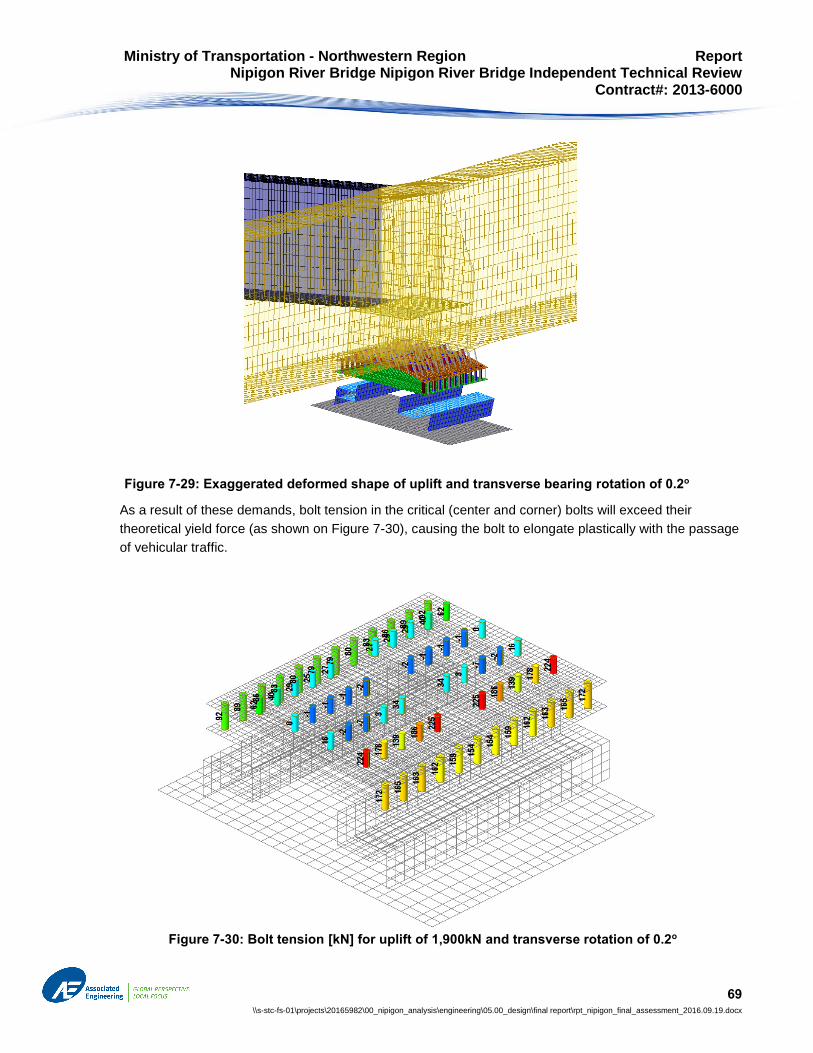
Ministry of Transportation - Northwestern Region Report Nipigon River Bridge Nipigon River Bridge Independent Technical Review Contract#: 2013-6000
69 \\s-stc-fs-01\projects\20165982\00_nipigon_analysis\engineering\05.00_design\final report\rpt_nipigon_final_assessment_2016.09.19.docx
As a result of these demands, bolt tension in the critical (center and corner) bolts will exceed their
theoretical yield force (as shown on Figure 7-30), causing the bolt to elongate plastically with the passage
of vehicular traffic.
Figure 7-29: Exaggerated deformed shape of uplift and transverse bearing rotation of 0.2o
Figure 7-30: Bolt tension [kN] for uplift of 1,900kN and transverse rotation of 0.2o

Ministry of Transportation - Northwestern Region Report Nipigon River Bridge Nipigon River Bridge Independent Technical Review Contract#: 2013-6000
70 \\s-stc-fs-01\projects\20165982\00_nipigon_analysis\engineering\05.00_design\final report\rpt_nipigon_final_assessment_2016.09.19.docx
Since analysis results show corner bolts yielding under dead load, vehicle passage on the bridge deck
would cause inelastic elongation of the corner bolts. Ultimate bolt elongations for this analysis case are
well under the 3.5% limit (see Figure 7-31). Although bolts would not immediately fail, they would be
exposed to low-cycle fatigue, leading to possible eventual progressive connection failure.
Prior to potential bolt low-cycle fatigue failure, stresses in the bevelled shoe plate would be below the
design yield of 350MPa (see Figure 7-32). However, the stress in some locations exceeds 248MPa, which
would result in shoe plate local yielding if it were A36 steel, as shown on bearing shop drawings. As the
bolts in the outer line fail in low-cycle fatigue, the load would be transferred to the inner line bolts,
dramatically increasing bending moment in the shoe plate, resulting in overstressing and yielding of the
shoe plate.
Figure 7-31: Bolt elongation [mm] for uplift of 1,900kN and transverse rotation of 0.2o

Ministry of Transportation - Northwestern Region Report Nipigon River Bridge Nipigon River Bridge Independent Technical Review Contract#: 2013-6000
71 \\s-stc-fs-01\projects\20165982\00_nipigon_analysis\engineering\05.00_design\final report\rpt_nipigon_final_assessment_2016.09.19.docx
7.2.3.2.3 Case 6 Design Evaluation: Bearing Longitudinal Rotation with Uplift Load of 3,370 kN
To determine the maximum rotation that the bearing can tolerate in combination with maximum ULS uplift at
the north bearing, we have applied constant uplift load Zf with increasing eccentricity e, until the bolts reach
maximum elongation of 3.5%, and recorded girder rotation in each step. The greatest rotation, obtained
just before first bolt failure at maximum eccentricity is the maximum bearing rotation under the specified
uplift load.
Finite element analysis results for the uplift load of 3,370kN (max ULS uplift in north bearing) are shown
below. Based on our analysis results, the bearing can withstand up to 0.8o of rotation, combined with uplift
force of 3,370kN; this rotation corresponds with uplift force longitudinal eccentricity of 200mm. As the uplift
force eccentricity increases from, axial tension on bolts connecting the beveled shoe plate and girder flange
exceeds the bolt capacity and bolts begin to yield. Elongation in critical (corner) bolts increases with
rotation. When rotation reaches 0.8o (corresponding with e=200mm), elongation in the corner bolts
exceeds 3.5%, causing the corner bolts to fail, as shown in Figure 7-34. Failure of the corner bolts triggers
a progressive failure of the bolted connection.
Figure 7-32: Von Mises stress [MPa] in plates for uplift of 1,900kN and transverse rotation of 0.2o

Ministry of Transportation - Northwestern Region Report Nipigon River Bridge Nipigon River Bridge Independent Technical Review Contract#: 2013-6000
72 \\s-stc-fs-01\projects\20165982\00_nipigon_analysis\engineering\05.00_design\final report\rpt_nipigon_final_assessment_2016.09.19.docx
In addition to bolt elongation, the stresses in the bearing plates were examined. Stresses in upper and
lower bearing blocks were determined to be generally under the yield stress of 248MPa, except for a few
localized areas. However, stress in bevelled shoe plate was near its yield (assumed to be 350MPa) for
centered load (e=0); the stress further increased with uplift eccentricity, causing plastic deformation of the
shoe plate. To account for inelastic plate deformation, the effective bending stiffness of the shoe plate was
reduced in the zones where resulting bending moments exceed plate plastic capacity, effectively modeling
yielding of the plate. Von Mises stresses in bearing plates for the critical stage are shown in Figure 7-34.
Figure 7-33: Bolt elongation [mm] for Zf=3,370kN and e=100mm. Note that maximum elongation is
3.7mm (>3.5mm), indicating bolt failure

Ministry of Transportation - Northwestern Region Report Nipigon River Bridge Nipigon River Bridge Independent Technical Review Contract#: 2013-6000
73 \\s-stc-fs-01\projects\20165982\00_nipigon_analysis\engineering\05.00_design\final report\rpt_nipigon_final_assessment_2016.09.19.docx
7.2.4 West Abutment Bearing Design Evaluation Discussion
The bearings at the west abutment do not have sufficient capacity to resist the uplift loads shown in the
contract drawings, in particular the factored (ULS) uplift load of 5,300kN on the centre girder. Using the
most optimistic assumption regarding construction tolerances, materials and installation, the tensile
capacity of the bearing was calculated to be in the order of 5,035kN. The bearing tensile capacity is limited
by the capacity of the 7/8”-A490 flange connection, as well as capacity of the shoe plate in bending. This
limiting uplift force was calculated under the assumption that the bearing and the bolts are ‘perfectly’
installed (with zero tolerances), and that there is no corresponding girder rotation. The bearing capacity
would be further reduced by any girder rotation, construction tolerance in bearing placement, lack of
bevelled washers under bolt nuts, and variation in installed bolt tightness.
The bearing design does not facilitate rotation when combined with uplift force; any girder rotation relative
to the abutment significantly increases stresses in the shoe plate and its connection bolts. Consequently,
the north-west bearing design is not able to tolerate a specified bearing rotation of 1.3o in combination with
ULS uplift force of 3,370kN. With an uplift force of 3,370kN, a bearing rotation of only 0.8o causes critical
bolts to fail in tension, contributing to the potential for progressive connection failure.
The bearing design was evaluated for a service load, including 1,900kN dead load reaction and bearing
rotation of 0.2o, longitudinally or transversely. Based on this analysis, this load combination will cause
Figure 7-34: Von Mises stress [MPa] in bearing plates; Zf=3,370kN’ e=100mm; Longitudinal Rotation =0.8o

Ministry of Transportation - Northwestern Region Report Nipigon River Bridge Nipigon River Bridge Independent Technical Review Contract#: 2013-6000
74 \\s-stc-fs-01\projects\20165982\00_nipigon_analysis\engineering\05.00_design\final report\rpt_nipigon_final_assessment_2016.09.19.docx
some of the bolts to yield, also consistent with conditions necessary for progressive low-cycle fatigue
failure.
7.3 BEARING FAILURE ANALYSIS
In addition to the analysis focused on bearing design evaluation described above, the following analysis
was conducted to assist in understanding the low-cycle fatigue failure of the northwest flange connection
bolts. For this purpose, loads present on the bridge from opening until failure were considered, as well as
geometric imperfections measured on site during the site investigation outlined in Section 4.
7.3.1 Applied Loads
To explain the north-west bearing failure, the following is considered:
1. Bridge dead load for structure in Phase One. Dead load analysis is described above.
2. Imperfections in bearing placement, measured in the field after bearing failure.
3. Live load consisting of one CL-625-ONT truck in the westbound lane obtained from the global
FE bridge model.
4. The possibility of slip (shear deformations) between the shoe plate and the girder flange plate.
Based on the global FE model analysis results, neither cold weather nor wind was a material cause of the
bearing failure.
Measurements taken of the neutral north-west bearing position post-failure, as described in Section 4,
indicate an average vertical difference of 4mm (7mm difference along the south guide bar and 1mm along
the north guide bar) in the longitudinal direction over the length of the shoe plate, with a slope toward the
centre pier. This difference has been included in the model as a corresponding longitudinal girder rotation of
+0.23⁰ to represent the initial installation condition.
The governing force and rotation demands on the north-west bearing from the passage of a truck
correspond with truck Position A and Position B as shown in Figure 7-35. Truck Position A results in a
maximum north-west bearing uplift load, and truck Position B results in the maximum positive longitudinal
rotation at the bearing. A summary of the applied truck demands, combined with the dead load uplift and
initial rotation, is shown in Table 7-2.

Ministry of Transportation - Northwestern Region Report Nipigon River Bridge Nipigon River Bridge Independent Technical Review Contract#: 2013-6000
75 \\s-stc-fs-01\projects\20165982\00_nipigon_analysis\engineering\05.00_design\final report\rpt_nipigon_final_assessment_2016.09.19.docx
For the purpose of presenting realistic low cycle fatigue potential, the assumed flange connection bolt (HA1)
trilinear tensile stress-strain curve was modified to represent the higher nominal capacity of 301 kN and
associated yield elongations (see Figure 7-7).
Figure 7-35: Truck positions for governing north-west bearing demands
Table 7-2: Summary of demands for truck passage

Ministry of Transportation - Northwestern Region Report Nipigon River Bridge Nipigon River Bridge Independent Technical Review Contract#: 2013-6000
76 \\s-stc-fs-01\projects\20165982\00_nipigon_analysis\engineering\05.00_design\final report\rpt_nipigon_final_assessment_2016.09.19.docx
7.3.2 Analysis Results
7.3.2.1 Girder to Shoe Plate Contact
A Phase One dead load only case, in combination with an average measured longitudinal out-of-tolerance,
was considered to provide an indication of the prying-induced contact force between the girder bottom
flange and shoe plate prior to the north-west bearing failure. This contact force was quantified by the
summation of the individual forces in rigid ‘compression-only’ elements between the girder bottom flange
and the shoe plate, as shown in Figure 7-36, resulting in a total of 513 kN of compression. This figure
displays only the modeled contact elements that experience compression forces; all other elements are
hidden from view, but the net contact forces are included.
The total contact force on the girder flange from prying of the shoe plate is 513kN. Frictional forces
between steel surfaces are known to be in the order of 20% of the applied force at the start of slip and
reduce to 12% once slip has occurred. The resistance to slip of the shoe plate could then be in the order of
62kN to 102kN. When compared to the resistance to slip along the lower sliding surface between PTFE
Figure 7-36: Compressive forces between plates from Phase One dead load from

Ministry of Transportation - Northwestern Region Report Nipigon River Bridge Nipigon River Bridge Independent Technical Review Contract#: 2013-6000
77 \\s-stc-fs-01\projects\20165982\00_nipigon_analysis\engineering\05.00_design\final report\rpt_nipigon_final_assessment_2016.09.19.docx
and stainless steel of 5% to 10% of the total uplift force of 1719kN equates to 86kN to 172kN, this analysis
and assessment that the possibility exists for slip to occur.
Slip of the shoe plate below the girder flange would introduce additional bending moments to the bolts
which have not been quantified in our analyses and will contribute significantly to the low-cycle-fatigue
cracks observed on the fracture surfaces of the bolts
7.3.2.2 Bolt Strain
Due to the effects discussed in previous sections, the flange connection bolts experience an uneven
distribution of forces, with a maximum force experienced by the west corner bolts. The bolt elongations from
the load combinations with the truck at Position A and Position B are summarized in Figure 7-37.

Ministry of Transportation - Northwestern Region Report Nipigon River Bridge Nipigon River Bridge Independent Technical Review Contract#: 2013-6000
78 \\s-stc-fs-01\projects\20165982\00_nipigon_analysis\engineering\05.00_design\final report\rpt_nipigon_final_assessment_2016.09.19.docx
Dead
Lo
ad
wit
h T
ruck P
osit
ion
A
Dead
Lo
ad
wit
h T
ruck P
osit
ion
B
Figure 7-37: Flange Connection Bolt Elongations [mm]

Ministry of Transportation - Northwestern Region Report Nipigon River Bridge Nipigon River Bridge Independent Technical Review Contract#: 2013-6000
79 \\s-stc-fs-01\projects\20165982\00_nipigon_analysis\engineering\05.00_design\final report\rpt_nipigon_final_assessment_2016.09.19.docx
Results of our analysis show that the most heavily loaded flange connection bolt (HA1), in the west corners
of the shoe plate, which would yield and inelastically elongate when a CL-625-Ont truck was in Position A.
The demands on the bolt would be reduced when the same truck is in Position B. This inelastic cycling
behaviour of the bolt indicates plastic bolt strains and the potential for low-cycle fatigue failure initiated in a
west corner of the shoe plate (Figure 7-38).
This analysis result is based on an average measured longitudinal out-of-parallel initial bearing condition.
Considering that the southwest corner of the lower guide is measured to be the highest, combined with the
evidence of the PTFE crushing in this corner, this analysis supports the conclusion that the highest initial
bolt strains were experienced in the southwest corner.
Figure 7-38: Results of single truck live load analysis

Ministry of Transportation - Northwestern Region Report Nipigon River Bridge Nipigon River Bridge Independent Technical Review Contract#: 2013-6000
80 \\s-stc-fs-01\projects\20165982\00_nipigon_analysis\engineering\05.00_design\final report\rpt_nipigon_final_assessment_2016.09.19.docx
7.3.2.3 North-west Bearing Failure Analysis Discussion
Based on the analysis, the repeated passages of single CL-625-ONT legal trucks along the bridge would
cause cyclic plastic strains and in the bolts connecting the bevelled base plate and girder flange.
With the combined Phase One dead load, installation imperfections, and the passage of a truck, the
analysis shows that the west corner bolts likely experienced cyclic inelastic elongation first. This is
consistent with an observation from site made of PTFE distortion in the south-west corner after bearing
failure, indicating high load concentration. Each passing truck over the bridge deck caused a cycle of
reduced and increased uplift reaction and translation in the longitudinal direction of the bridge, leading to
low-cycle fatigue of the highest loaded bolt. This process progressed, and ultimately resulted in complete
connection failure.
Other factors, such as wind effects, additional uplift force due to cable thermal loads, or bearing translation,
may have increased the uplift force and expedited the failure of the bearing assembly; but those effects are
relatively minor.
A lack of bolt pretension and variation in bolt tightness may have accelerated the bearing connection failure,
due to further uneven force distribution among the bolts. The local bending of the bolts, due to a lack of
beveled washers and transverse prying deformations of the shoe plate, further accelerated the bolt failure.

Ministry of Transportation - Northwestern Region Report Nipigon River Bridge Nipigon River Bridge Independent Technical Review Contract#: 2013-6000
81 \\s-stc-fs-01\projects\20165982\00_nipigon_analysis\engineering\05.00_design\final report\rpt_nipigon_final_assessment_2016.09.19.docx
8 Discussion
Previous sections of this Report described information assembled and generated regarding the
circumstances contributing to the failure. They emphasized factual information, modelling and analysis
results, and assessments and interpretations of information within sections. This section integrates our
findings into the factors contributing to the failure of the bearing.
These findings are based on the Site Visit Observations, Bolt Investigation Review, Document Review,
West Abutment Bearing Evaluation and engineering interpretations by Associated Engineering (Ont.) Ltd.
(AE) The bolt testing reports by NRC and SSW, and the fracture surface interpretations by NRC, provided
critical physical information and material behaviour assessments that were considered in our investigation
and contributed to our conclusions.
The Site Visit Observations undertaken by Associated Engineering staff revealed key information including:
The shoe plate had undergone plastic deformation, as evident from the permanent deflected
shape of this plate.
The bearings were observed to be unable to freely accommodate rotation about either major axis.
The masonry and sole plates were misaligned at all bearings.
Bolts supplied to site were too long requiring multiple flat washers to achieve a snug tight
condition. This snug-tight condition appears not to have been achieved consistently for all of the
bolts on the north-west bearing. The bolts were not pre-tensioned.
The final detailing of the shoe plate and the machined recesses made it difficult to tighten the
bolts. Access to the bolt heads became difficult following the upper bearing assembly installation,
and recess dimensions were too large to effectively prevent bolts from rotating, but too small to
allow a socket to be inserted to hold the bolt heads
The centre-west bearing required ¼ to ½ turns of the nut after failure of the north-west bearing
indicating the bolts were possibly loose and/or un-tensioned at the time of failure.
Clear evidence of sliding of plates on bolt shanks was observed. These demonstrate conclusively
that horizontal movements occurred at the interface of the shoe plate and girder flange.
A detailed review of the NRC and SSW reports combined with an independent visual review of all the bolts,
provided the following critical information and findings:
Bolts failed progressively due to cyclic loads combined with high axial tensions that caused low-
cycle fatigue cracks.
Crack propagation from one vs two sides indicates different types of loading causing failure
Corrosion on bolt fracture surfaces indicate early failure of some bolts. The south-west bearing
quadrant included five bolts with evidence of early failure.

Ministry of Transportation - Northwestern Region Report Nipigon River Bridge Nipigon River Bridge Independent Technical Review Contract#: 2013-6000
82 \\s-stc-fs-01\projects\20165982\00_nipigon_analysis\engineering\05.00_design\final report\rpt_nipigon_final_assessment_2016.09.19.docx
The outer lines of bolts exhibit flat failure surfaces and two-sided crack propagation consistent
with high axial tension coupled with alternating flexural tension causing low-cycle fatigue, while the
inner lines of bolts generally show steep failure surfaces consistent with one-sided crack
propagation with high axial tension causing low-cycle fatigue
All bolts displayed striations consistent with low-cycle fatigue ending in ductile fractures in high
tension.
The Review of Documents yielded several observations that influenced the bearing behaviour. These
observations include:
Shoe plate and bearing installation was undertaken in a manner unable to meet construction
tolerances.
The installed bearing assembly did not satisfy construction tolerances outlined in OPSS 922.
The bearing cannot freely accommodate rotation while subjected to uplift.
In addition to the site investigations, bolt observations and document review, AE engineers undertook a
series of global and local finite element analyses to determine demands on the bearings and other
components and to investigate the local behaviour of the bearing assembly. The local finite element
analyses subjected the bearing assembly to a number of demand combinations including uplift and rotation
both in the longitudinal and transverse directions. These analyses were used to both evaluate the design of
the bearings and to investigate the behaviour of the bearings in it’s “as-built” condition when subjected to
service loads. Key observations from this series of analysis include:
The north-west bearing design evaluation showed that the bearing assembly was inadequate for
all design evaluation cases except for service dead load only with no rotation.
Bolt tensions were amplified significantly from prying effects of the relatively flexible shoe plate
and the arrangement of bolts.
Shoe plate flexure coupled with loose bolts cause conditions where contact pressured between
the shoe plate and flange were reduced. This created the potential for sliding displacements
across this interface.
Design evaluation cases confirmed that the bearing assembly could not freely accommodate
specified rotational demands while subjected to uplift, without causing unintended demands in
bolts and plates comprising the bearing assembly.
Design evaluation cases indicated yielding of the flange connection bolts resulting in either low-
cycle fatigue potential or tensile failures.
Shear stresses would occur from traffic loads and temperature effects at the interface beneath
the girder flange and shoe plate. These stresses would be limited by PTFE friction within the
bearing.

Ministry of Transportation - Northwestern Region Report Nipigon River Bridge Nipigon River Bridge Independent Technical Review Contract#: 2013-6000
83 \\s-stc-fs-01\projects\20165982\00_nipigon_analysis\engineering\05.00_design\final report\rpt_nipigon_final_assessment_2016.09.19.docx
These key findings are discussed below.
8.1 PHYSICAL CAUSE OF FAILURE
The north-west bearing bolt group failure was through a progressive low-cycle, plastic-strain fatigue fracture
under high axial tension. The bolts failed progressively over time rather than in a single, sudden
event. Nine bolts were assessed as failing early as evident from corrosion seen on the fracture
surfaces. All of the failed bolts showed striations consistent with low-cycle fatigue at high strains. Some of
the bolts fractured primarily in high axial tension under cyclic loading. Other bolts fractured in high axial
tension combined with cyclic bending. The contributing causes to the individual bolt failures and to the bolt
group failure overall are described throughout this report and discussed together in this Section.
Twelve of the 14 bolts examined by NRC displayed progression fracture surfaces propagating from one
side of the bolts consistent with cyclic direct tension. Two of the bolts displayed fatigue crack growth from
two sides and NRC reported that they likely also experienced bending during loading. Four bolts examined
by SSW showed that the failure surfaces were more consistent with cyclic bending combined with high axial
tension. SSW also reported some bolts as failing before others based again on the corrosion product seen
on some of the bolts.
Our analyses of the various demands on the shoe plate / bearing/ bolt system, and of the local
deformations, stresses and strains in the bolts and shoe plate, are consistent with the failure surfaces
observed and a finding of progressive bolt failure. Analyses show that strains in the bolts arising from
heavy but highway-legal trucks, when combined with permanent dead load uplift, with the bearing’s inability
to freely rotate while in uplift, and with the out-of-parallel installation of the bearings would have been within
their post-elastic (plastic) range and sufficient to cause low-cycle fatigue fractures. Horizontal bending
stresses were introduced into some bolts, typically in the outer two lines of bolts having the highest initial
tensions, which contributed to their fracture. Bending effects arose from length changes in the bridge deck
under traffic and thermal effects causing longitudinal displacements at the bearing. The bearings were
intended to accommodate these deformations through sliding along low-friction PTFE sliding surfaces.
However, local damage to the PTFE caused an increase in friction and allowed bolts to experience
bending.
The bolts were not pre-tensioned on installation, and this also contributed materially to the failure including
to the bending effects initially in outer lines of bolts. The beveled shoe plate was too thin and flexible, and
this also contributed to increases in bolt forces that contributed to the failure.
That there were several important contributing causes and mechanisms is important, and each are
discussed in this Report and described below. The occurrence of all of these in combination is unique and
was highly improbable, however a confluence of events and conditions is typical of failures within
structures.

Ministry of Transportation - Northwestern Region Report Nipigon River Bridge Nipigon River Bridge Independent Technical Review Contract#: 2013-6000
84 \\s-stc-fs-01\projects\20165982\00_nipigon_analysis\engineering\05.00_design\final report\rpt_nipigon_final_assessment_2016.09.19.docx
8.2 PRYING EFFECTS
The forces and strains in the outer two lines of bolts (“lines” of bolts are oriented parallel to the roadway)
were increased significantly by transverse prying effects arising from flexibility of the bevelled shoe plate
between the bearing and the girder flange. The prying effects cause the majority of the uplift load to be
carried by the outer line of bolts.
In addition to the elastic flexibility of the shoe plates, yielding and plastic strains also occurred in the shoe
plate during the bolt fracture propagation which allowed the shoe plate to deflect further. Yielding was
clearly evident in the permanent deformation of the plate following failure. Both elastic prying effects and
plastic behaviour in the shoe plate contributed to increased strains in the bolts. Both effects contributed
materially to the progression of the bolt fractures.
Bolts were countersunk into the shoe plates which would have weakened and softened the shoe plates.
The analysis in this report did not include the removal of base metal from the shoe plates since the design
review demonstrated that the shoe plate, even without this weakening effect, was inadequate for the
demands specified for the tie-down bearings. A thicker, stiffer and stronger shoe plate would not have
reduced the risk of bolt failure to acceptable levels, but could have delayed the fracture of the bolts within
the group.
8.3 BEARING DEFICIENCIES
The inability of the tie-down bearings to freely accommodate rotation in an uplift condition caused increased
bolt forces and contributed to plastic strains in the bolts. These increases arise from the deformations
imposed on the bolts and shoe plate by the bridge superstructure. The bearing system design neither
isolated the bolt groups from these deformation demands nor accommodated the specified demands in the
flange-to-bearing bolted connection. Based on analysis, observation, our understanding of the bearing
behaviour, and measurements, the tie-down bearing arrangement was inadequate and inappropriate for the
requirements of this bridge.
In addition, there were a number of variations on the fabrication drawings relative to the contract
drawings. These are described in detail in Section 6. Important variations from the construction drawings
included the use of A36 steel (minimum 248 MPa) where 350 MPa yield stress was specified, an apparent
error in shoe plate bolt lengths, bevelled washers were not included, and changes were made to the grade,
number and spacing of bolts. These are variations, and while some are not necessarily errors, all of these
affected the bearing behaviour and required consideration in the failure assessment. There were also
variations noted in the bearing design relative to OPSS specifications, as outlined in Section 6.
8.4 BOLT INSTALLATION
Observations on bolt dimensions and installation were provided in Section 4.4. Implications are described
below. The review of the documents, construction records and discussions with site staff confirm that the
40 flange bolts in each of the two west abutment bearings were not pre-tensioned (tightened) during
bearing installation. The bolts supplied were too long and did not have sufficient thread length to allow

Ministry of Transportation - Northwestern Region Report Nipigon River Bridge Nipigon River Bridge Independent Technical Review Contract#: 2013-6000
85 \\s-stc-fs-01\projects\20165982\00_nipigon_analysis\engineering\05.00_design\final report\rpt_nipigon_final_assessment_2016.09.19.docx
tensioning without installing washers or shim plates. Discussions on site with project representatives from
the Ministry revealed that the bolts of the centre-west bearing required a ¼ to ½ turn of the nut to reinstate
tension. It is expected a similar condition existed in bolts of the failed north-west bearing. In addition, flat
washers were installed during bearing installation, and a permanent solution comprising galvanized shim
plates was proposed and accepted but had not been installed. Bevelled washers would still have been
necessary as part of this retrofit. Five washers were provided on each bolt, although the shoe plate bevel
required that an increasing number of washers were needed to provide consistent nut purchase onto
threads on all of the bolts. Figure 4-7 showed also that nut purchase onto the bolts did not vary in the
uniform manner expected, and as such the bolts were not snug-tightened or pre-tensioned consistently
along the length of the bolt group. Axial tensions within the bolts would have varied significantly
contributing to unequal bolt forces, fewer bolts contributing to uplift resistance, and affecting flexural effects
within the shoe plate and girder flange.
The lack of bolt pre-tension also meant that there was inadequate ‘clamping’ or pre-tensioning force
between the plates in the connection. Properly pre-tensioned bolts experience tensile strains close to or
beyond their initial yield strain. As long as the bolt pre-strain is not exceeded by applied force or
deformation demands then the strains in the bolts remain nearly constant, and low-cycle fatigue failure does
not occur. In addition, the lack of pre-tensioning implies that initial forces and strains in various bolts are
neither uniform or predictable. As such many non-linear analysis scenarios would be needed to
characterize the patterns of progression of bolt fracture. The lack of pre-tension also reduced shear friction
resistance at the shoe plate to flange plate interface as a result of bolt elongations. This introduced the
potential for bending strains into the bolts.
The flat washers caused initial, internal bolt force eccentricity and bending. Owing to the high bolt axial
tensions, this would have caused bolts to yield and rotate immediately below the nuts causing internal bolt
force eccentricities to reduce. This would have subsequently allowed for alternating flexural tensions and
symmetric crack propagation as discussed in Section 8.7. As such, the flat washer profiles do not appear
to be a primary factor in the bolt group failure overall. However, some or all of these factors would have
contributed to either a decision or an omission to tension the 40 (ASTM-A490) bolts in each west bearing.
While the flat washer profile is not assessed as a primary facture in the failure, the lack of bolt pre-tension
on installation was found to have contributed materially to the failure of the north-west bearing in a number
of ways. These include:
Non-uniform bolt forces and hence reduced load sharing among bolts.
Lack of clamping pressure which allowed repeated, high bolt axial strains to occur.
Lack of friction between the shoe plate and girder flange which allowed shearing across this interface, and consequently created a condition in which bolt bending could occur.
8.5 BEARING INSTALLATION
Sections 8.3 and 8.4 discussed important bearing attributes and bolt installation factors that influenced the
behaviour of the bearing assembly overall. Importantly, the site installation of the west abutment bearings

Ministry of Transportation - Northwestern Region Report Nipigon River Bridge Nipigon River Bridge Independent Technical Review Contract#: 2013-6000
86 \\s-stc-fs-01\projects\20165982\00_nipigon_analysis\engineering\05.00_design\final report\rpt_nipigon_final_assessment_2016.09.19.docx
also affected the behaviour of the bearing and contributed to the conditions allowing failure to
occur. Factual site observations on the bearing installation were included in Section 4.3 – Installed Bearing
Condition. As part of our review of documentation related to the bearings in Section 6.2 – Bearing
Installation and Construction Tolerances, important aspects of the in situ bearing installation were also
described. This section integrates these factors and their contribution to the bearing behaviour.
The bearing assemblies were installed out-of-parallel relative to the shoe plates and the abutments. The
rotations induced in the north-west bearing assembly from these out-of-parallel dimensions, as seen in
Figure 4-4, were 0.17° transversely (corresponding to an out-of-parallel condition of 3 mm) and 0.40°
longitudinally (out-of-parallel 7mm). In combination with the rigidity of the bearing, i.e. its inability to freely
accommodate rotations while in uplift, these imposed rotations caused bolt forces to redistribute within the
bolt group. The resultant of the 40 bolt forces would have been eccentric to the bearing center. Some bolt
forces therefore increased and load sharing among the bolts was significantly less uniform. This increase
in bolt forces was significant when combined with the lack of bolt pre-tensioning and with the passage of
heavy trucks. Similar but larger out-of-parallel dimensions were recorded in the center-west bearing.
This shifting of the uplift force resultant, and the re-distribution of forces within bolts, occurred in both
primary directions. The distribution of forces between the contact pressures on the upper and lower guide
bars was also significantly affected. Transverse rotations caused more of the uplift force to be resisted on
one guide bar more than the other. The longitudinal rotations lead to a gradient of contact pressures along
each guide bar, with higher pressures at one end. Both of these also affected the contact pressures
between the PTFE (Teflon) strips on the upper and lower guide bars. For the north-west bearing, contact
pressures would have been highest at the southwest corner of the assembly as discussed in Section 4.3
and as seen in the photographs of Figure 4-5. Those photos show the bearing in an unloaded condition
following failure. While in service, these high local pressures caused local damage to the PTFE, also as
seen in Figure 4-5. Under these conditions, the co-efficient of friction of the PTFE would have increased
from the very low values intended for proper bearing function. An increase in the friction between the PTFE
layers of the guide bars was necessary to allow significant shearing forces to be generated in the flange
connection bolts, which was the key factor in the two-sided fracture propagation seen in these bolts. This
out-of-parallel installation therefore is assessed as contributing materially to the fracture of the bolts
connecting the bearing assembly to the girder flange. Additional discussion on the friction, bearing
demands, sequence and interaction of this and other factors is summarized in Section 8.7.
8.6 STRUCTURAL DEMANDS ON BEARINGS
The global FE analysis of the bridge confirms that the uplift force on the northwest bearing before the failure
occurred was at or near 1,720 kN, which was in general agreement with the contract drawings for this bearing
and condition. At that time, the uplift on the north-west bearing was significantly higher than the uplift on the
centre-west bearing. It is noted that the centre-west bearing will have an uplift force significantly higher than
the northwest bearing in the final, four-lane finished condition. It was this larger design force that governed
the bearing design requirements, and the north-west bearing could have been designed for a lower uplift
force, if refined accordingly. The fact that the north-west bearing failed at demands far lower than its specified,
or apparent capacity, demonstrates the significant degree of structural inadequacy of the bearing
components.

Ministry of Transportation - Northwestern Region Report Nipigon River Bridge Nipigon River Bridge Independent Technical Review Contract#: 2013-6000
87 \\s-stc-fs-01\projects\20165982\00_nipigon_analysis\engineering\05.00_design\final report\rpt_nipigon_final_assessment_2016.09.19.docx
Analyses indicate that bolts on the north-west bearing would have yielded under demands from legal highway
trucks which place additional uplift and rotational demands on the west bearings. The analyses undertaken
shows that these demands are sufficient to cause axial plastic strains in the bolts. Overload permits issued
by MTO indicate that just under ninety trucks over 60 tonnes (the weight of a code design truck) potentially
crossed the bridge. The number of heavy trucks crossing the bridge is similar in magnitude to the number of
crack propagation cycles seen in the striations on the fracture surface of some of the bolts.
In conjunction to the analysis of the dead and live load demands, wind effects on the structure were evaluated
and found to increase uplift forces by approximately 10% of the reaction caused by bridge’s self-weight. This
is not sufficient to contribute significantly to plastic strain accumulation in the bolts. The bridge was unlikely
to have experienced winds of this magnitude during the short period that the west bearings were installed.
Thermal effects on the structure were also investigated for their effect on relative demands placed on the
north-west bearing. It was found that cold temperature effects, specifically relative changes in cable
temperatures increased the uplift forces by approximately 10% of the reaction caused by bridge self-weight.
This load would have occurred simultaneously with the effects from truck traffic and while this would have
accelerated the failure of the bolt group it would have not materially changed the failure mechanism.
Charpy impact testing on the bolt steel was conducted at -27.9° Celsius and returned minimum average
energy values (J) meeting all code minima required by CHBDC. This suggests that significant cold-
temperature embrittlement of bolts would not be expected. Failure surfaces were seen to be ductile, which
directly supports this conclusion.
8.7 BOLT FRACTURE AND CONTRIBUTING FACTORS
Shoe plate to flange bolts failed under high tensions with cyclic, alternating tensions. Accompanying
several bolt fractures was clear evidence of striations propagating from both sides towards the bolt centers.
This pattern indicates that alternating flexural effects were present. Discussions with the lead NRC
investigator confirmed that direct bending effects in the bolts would be necessary for this pattern of
striations to occur. Therefore, a mechanism to explain this final fracture behaviour is necessary and is
provided below. The following discussion combines and extends observations and partial behaviour
mechanisms descriptions by NRC, MTO and AE engineers.
Fundamentally, the amplified bolt forces from shoe plate flexure, prying and eccentricities of the bolt group
resultant reactions (arising from the bearing’s inability to rotate freely in uplift) as well as the lack of bolt pre-
tension, were fundamental to the tie-down bolt failures. The bearing assembly, connections, interface
elements and installation were materially deficient as evidenced in this report. However, without additional
effects, the bolt fractures and bearing failure would likely have been delayed or prevented and the two-
sided fracture patterns could not have occurred.
Several observations are important to the bolt fracture patterns seen, including:
The evidence of very high bolt tensions from the shoe plate permanent yield deformations.

Ministry of Transportation - Northwestern Region Report Nipigon River Bridge Nipigon River Bridge Independent Technical Review Contract#: 2013-6000
88 \\s-stc-fs-01\projects\20165982\00_nipigon_analysis\engineering\05.00_design\final report\rpt_nipigon_final_assessment_2016.09.19.docx
Figure 5-3 shows that the two-sided crack propagation patterns generally orient transversely to the
roadway, suggesting longitudinal alternating horizontal bending demands. Our independent
examination of the failed bolts and each bolt’s fracture patterns allowed us to locate or confirm the
location of most of the bolts onto the bolt group ‘template’ as seen in Figure 5-3.
Figure 5-3 illustrates two or more patterns of behaviour, with patterns changing as bolt failures
progressed.
Site observations and measurements of out-of-parallel bearing guide bars and significant local
damage to the PTFE, in particular at the southwest corner of the failed bearing. The damage
observed was seen following failure, with the uplift loads removed. The PTFE was shown to be
highly and locally over-stressed and damaged. In service under uplift the PTFE would have been
crushed, with less capacity to allow for a smooth, low-friction sliding behaviour as was necessary.
Bolts supplied were measured and confirmed as too long with thread lengths shorter than
standards for this length.
At least two bolts in the outer line of the southeast quadrant were observed to be loose, as seen in
fewer than expected exposed threads.
Rub marks were seen on the bolt shakes which clearly show shear movements at the shoe plate
interface.
A mechanism and sequence of bolt failures that is consistent with the observations, forensic investigations
and analyses is provided below:
Bolts in the outer two lines are heavily loaded. Some of these bolts may have been snug tight;
some in these lines were not. The bolts that were tightened, and also having the highest tension
from prying, yielded in tension under dead loads and imposed deformations. Additional demands
from truck loads have been shown to be sufficient to lead to tensions beyond yield in outer bolts.
These highly loaded bolts would have reached the plastic strain plateau of the stress-strain curve.
Owing to the use of flat washers and the bearing surface slope at the nuts, these bolts would also
have yielded in flexure, in as little as one load cycle, which would bring the nuts ‘flat’ onto the
washers. This yielding was from the applied eccentric bolt tension at the 0.8% out-of-parallel of the
flat washers, but also from the out-of-parallel of the bearing installation. Following this yield event,
the underside of the nuts sit flat and the bolts tend towards uniaxial, concentric tension. The initial
local eccentricities are reduced or eliminated by plastic redistribution.
With these bolts in this condition, they are in a ‘fix-fix’ condition for any added flexure from
horizontal loads. Because they are on or near the yield plateau, any small additional cyclic,
horizontal shear forces can cause bolt flexure in double-curvature and additional plastic strains on
one side of the bolt thread or the other.
With several bolts in this condition, in fix-fix flexure and high tension (tension stiffened), they are
relatively stiff and resist horizontal loads with little horizontal deformation. This shear flow load path
at the interface between the shoe plate and flange plate would experience these effects if friction
between the shoe plate and flange plate was overcome. The shear-oriented movements could be
very small, and would not necessarily produce ‘scratch’ patterns on either of the sliding plates.
However, clear evidence of sliding movements was seen in polishing marks on the bolt shafts.

Ministry of Transportation - Northwestern Region Report Nipigon River Bridge Nipigon River Bridge Independent Technical Review Contract#: 2013-6000
89 \\s-stc-fs-01\projects\20165982\00_nipigon_analysis\engineering\05.00_design\final report\rpt_nipigon_final_assessment_2016.09.19.docx
Bolts in the inner lines were shown by non-linear analyses to be under much lower tensions in this
phase, and as such would be ‘loose’ and not participating in resisting shear deformations. Some
may have experienced shear flows through a different mechanism, but which would not contribute
to bolt cracking, nor prevent shears in the bolts with the tension-stiffening.
Horizontal shear forces in the bolts would be small when the PTFE guides were smooth and
functioning with low friction. However, with local crushing of the PTFE the friction force would
increase significantly, increasing bolt shear forces. The out-of-parallel bearing installation, and
observations of damage to the PTFE in the southwest corner of the bearing, implies that the
frictional force would be greater than intended, and the bearing would have been effectively locked
(frozen) at the time.
A portion of the prying effects arise from internal contact pressures between the shoe and sole
plates. Analyses show that flexural deformation of the shoe plate was a more significant contributor
to bolt force increases. Analyses in Section 7 indicate that under service load conditions, internal
contact forces of approximately 510 kN under service conditions may occur for a loose bolt
condition. For a friction co-efficient between the shoe and sole plates of approximately 0.2 (as an
indicative value) then a longitudinal shear force as low as 0.2 x 500 = ~100 kN would be sufficient
to overcome this friction and allow shear forces to be generated in the tension-stiffened bolts. A tie-
down reaction of at least 1720 kN (dead load only, greater under DL+ LL) would be experienced by
the PTFE surfaces. A co-efficient of friction as low as 6% in the damaged PTFE would be sufficient
to allow bolt shears to occur. Frictional forces between stainless steel and PTFE could be in the
range of 5% but never more than 10% for filled, undamaged PTFE. Horizontal longitudinal
displacements at the northwest bearing under truck loads cycle between approximately -1 mm and
+ 2 mm. This would increase further if secondary bearing displacements from girder rotations and
the eccentricity of the bearing from girder’s neutral axis were added. Even at these small,
conservatively derived displacements, significant shear forces would develop in the bolts. A
supporting analysis with the north-west bearing assumed to be ‘locked’ indicates bearing shear
forces ranging from approximately -590 kN to +820 kN caused by the passage of a heavy, legal
truck.
These horizontal forces (or displacements) would be sufficient to generate shears, moments,
plastic strains and low cycle fatigue crack propagation in the bolts from alternating directions.
In addition to truck loads, temperature effects cause horizontal forces (with bearings locked) as the
deck length changes under thermal changes. These effects would occur both alone and in
combinations with truck passages.
These alternating strains in the tension-stiffened bolts cause cyclic horizontal shears consistent
with cracks propagating from two sides until the eventual ductile tensile fracture occurs.
Failure of each bolt in turn causes uplift loads to shed to other bolts (some in outer lines, some
inner). Bolt crack propagations don’t increase axial strains in adjacent bolts until bolt failure.
As the outer bolts fracture, the forces shift to the inner bolts. Prying becomes much reduced
because the system has changed, but the share of the total uplift load per bolt increases.
The crack patterns seen in Figure 5-3 show that the inner bolts fail in tension but predominantly with one-
sided crack propagations. This indicates that the horizontal shears and bolt bending are reduced. A one-
sided crack propagation under high axial tension and incremental plastic strains from increased loads,
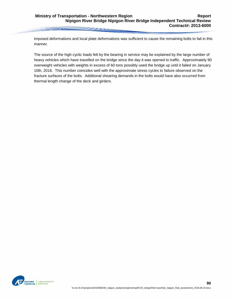
Ministry of Transportation - Northwestern Region Report Nipigon River Bridge Nipigon River Bridge Independent Technical Review Contract#: 2013-6000
90 \\s-stc-fs-01\projects\20165982\00_nipigon_analysis\engineering\05.00_design\final report\rpt_nipigon_final_assessment_2016.09.19.docx
imposed deformations and local plate deformations was sufficient to cause the remaining bolts to fail in this
manner.
The source of the high cyclic loads felt by the bearing in service may be explained by the large number of
heavy vehicles which have travelled on the bridge since the day it was opened to traffic. Approximately 90
overweight vehicles with weights in excess of 60 tons possibly used the bridge up until it failed on January
10th, 2016. This number coincides well with the approximate stress cycles to failure observed on the
fracture surfaces of the bolts. Additional shearing demands in the bolts would have also occurred from
thermal length change of the deck and girders.

Ministry of Transportation - Northwestern Region Report Nipigon River Bridge Nipigon River Bridge Independent Technical Review Contract#: 2013-6000
91 \\s-stc-fs-01\projects\20165982\00_nipigon_analysis\engineering\05.00_design\final report\rpt_nipigon_final_assessment_2016.09.19.docx
9 Conclusion
This report outlines both the observations and analysis undertaken by Associated Engineering (Ont.) Ltd to
outline the key factors that contributed to the failure. These key factors resulted in the failure of the tie-down
bearing:
The failure of the tie-down bearing was caused by the complete fracture under cyclic loading of all
40 A490 bolts connecting the north-west bearing assembly to the main girder of the bridge deck.
Individual bolts within the group failed at different times over a period of several weeks.
The fracture mechanism was a progressive low-cycle fatigue caused by high bolt forces in tension
arising from bridge uplift at the west abutment, coupled with, in some cases, cyclic bending of the
bolts. The crack propagation patterns on fracture surfaces indicate that bolt bending occurred and
was strongly oriented in a longitudinal direction. All bolts showed evidence of low-cycle fatigue.
The bolts failed gradually while experiencing repeated cycles of axial and bending effects from
heavy but legal truck traffic. Temperature effects in the bridge deck and cables also contributed, to
a minor degree, to bolt demands.
The high tensile forces and strains in the outer two lines of bolts were caused by flexibility of the
shoe plate and related prying effects between the shoe plate and the girder flange. Yielding of the
shoe plate from the high bolt forces was evident in the permanent bend of the shoe plate.
The stiffness and lack of rotation capacity of the tie-down bearings, when acting in uplift,
contributed significantly to increased bolt forces and strains.
The out-of-parallel installation of the bearing, coupled with the bearing’s inability to freely rotate,
contributed to a non-uniform bolt force distribution and to local damage and increased friction in the
PTFE (teflon) guides within the bearing guide bars.
The flange connection bolts were not pre-tensioned (tightened) during bearing installation. This
lack of pre-tensioning, in combination with effects noted above, allowed the shoe plate and girder
flange to slide against each other, which in turn allowed horizontal shear forces and bending to
occur in the bolts.
The bolt material met all specifications and bolts were not embrittled by either the coating or by cold
temperatures.
The north-west bearing failed on January 10, 2016. The centre-west bearing did not fail and so limited
damage to the bridge which provided the opportunity for MTO to implement emergency repairs and re-
instate single lane traffic on the Trans Canada Highway within a day. Both bearings were subsequently
bypassed with two sets of redundant, temporary tie-down assemblies to allow the bridge to re-open to two
lanes of normal unrestricted traffic.

92