Embed Size (px)
Citation preview

Niobrara Resource Play
Niobrara, Colorado/Wyoming
January 18th, 2012
Ryan Landry & Nate Wilke

General Outline
Introduction
Beginning the Project
Formation of the team
Monitor wells and data acquisition
Early well design
First horizontal
Lessons Learned
Wellbore stability issues
Well construction and design
Current Drilling Techniques
BHA design
Directional planning/considerations
Geosteering
Future Plans
Drilling/Completion optimization
2

Beginning the Project
3
Spreading our HES culture
New area, same culture
Formation of Highly Integrated Team
Diversified, yet focused
Ensure overall project success
– Efficiency
– Adaptability
– Flexibility
– Creativity

General DJ Basin Information
4
Pierre Shale
Tertiary
PrecambrianBasement
Wyoming
Colorado
• Ranges from 275 to 400 feet thick in the DJ Basin
• Thickness increases to the west
• Interbedded brittle chalk and ductile shale
• Three main carbonate-rich benches 10 to 25 feet per bench, total thickness up to 70 feet thick
• 5 to 12% porosity
• Small faults are common in Niobrara
• Oil is self-sourced from interbedded organic-rich shales

Evaluating the Niobrara
Monitor/Test Wells
Data Acquisition
Drilling data
Geological samples
Extensive wireline logging
Reservoir data
Frac Monitoring/Evaluation
Vertical Seismic Profiles
Permit two possible horizontals, choose one.
Establish development areas/techniques
5

Sh-max/Sh-min orientation and lateral placementDrill the lateral as perpendicular to SHmax as possible (parallel with Sh-min) in order to maximize the hydraulic fracture
stimulation.
6
DIF
BKO
SH-Max
Sh-min
S h max
S h min

35
4.5
ft o
f w
ho
le
core
A
B
C
Fort Hays
Greenhorn
Sharon Springs
UB
LC
90.2
5 ft
90 f
t90
.25f
t
SHmax
Fault and N. Fractures showing N 58 E strike directions in line with the present day stress Field.
Static Dynamic
Greenhorn (calcite –rich siltstone showing Inoceramus traces)
Natural fracture stained with oil (core depth at 6873 ft)
Oil seeping out from Niobrara chalks and marls
10 ft
40 ft
84.0
4 ft
NaturalFractures
0 90
Fault
1 ft
Coring Operations

8
Early Horizontal Well Design
13-3/8” Surface
9-5/8” Production
6 deg./100’ Curve
20” Conductor+/- 90’
+/- 750’
+/- 6500’ TVD
KOP +/-5500’
Nio A
Nio C
Nio B
Set 20” conductor at +/- 90’
Drill 17-1/2” hole to +/- 750’
Set 13-3/8” surface casing
Drill 12-1/4” intermediate hole Vertical to KOP @ +/- 5500’
Drill curve w/ 6 deg./100’ BR – land @ ~90 deg.
Drill +/- 5000’ lateral to +/-11000’ TMD
Set 9-5/8” intermediate casing
Drill 8-3/4” production hole
Set 5-1/2” production casing

First Horizontal
9
0
2000
4000
6000
8000
10000
12000
14000
0 10 20 30 40 50 60
De
pth
Days
DVD actual DVD planned
Not getting BR’s, TOH to dial up motor multiple times
Multiple wiper trips due to Sharon Springs
Ran 9 5/8” casing - could not get through Sharon Springs
Drill out of 9 5/8” casing
Attempt to run 7” liner multiple times
Run drillable casing with reamer shoe to get throughSharon Springs
Obviously, we ran into a few problems…

First Horizontal
10

Lessons Learned
11
In-house drilling specialists conducted wellbore stability research from horizontal well data, monitor well logs, & directional plan
Discovered root cause – mechanical instability, not chemical
Back to the drawing board
Tailored directional plan to incorporate findings
Well Construction:
Smaller hole sizes, smaller directional tools, higher build rates, less shale exposure
Discussed with company men the importance of monitoring hole conditions through curve

12
Current Niobrara Well Design
9-5/8” Surface
7” Production
11000’ TD
6” Hole
Set 16” conductor at +/- 90’
Drill 12-1/4” hole to +/- 750’
Set 9-5/8” surface casing
Drill 8-3/4” intermediate hole Vertical to KOP @ +/- 5500’
Drill curve w/ 10-12 deg./100’ BR
Land curve in Nio B interval at +/-90 deg. inc.
Set 7” intermediate casing
Drill +/- 5000’ of 6” lateral to +/- 11,000’ TD
Run 4-1/2” cemented liner10-12 deg./100’ Build
16” Conductor+/- 90’
+/- 750’
KOP +/-5500’
Nio A
Nio C
Nio B

13
Niobrara B
Niobrara B_sh
1 mile
NW SE
Niobrara A 25 10 15 5010 5 25
Codell
SE
Drilling Issues - Faulting
Courtesy of Geophysical Pursuit, Inc - Geokinetics

14
Geosteering - Faulting
VS
MD
TVD
Saw most faults on seismic, able to plan wellbore through them, threading the
needle.
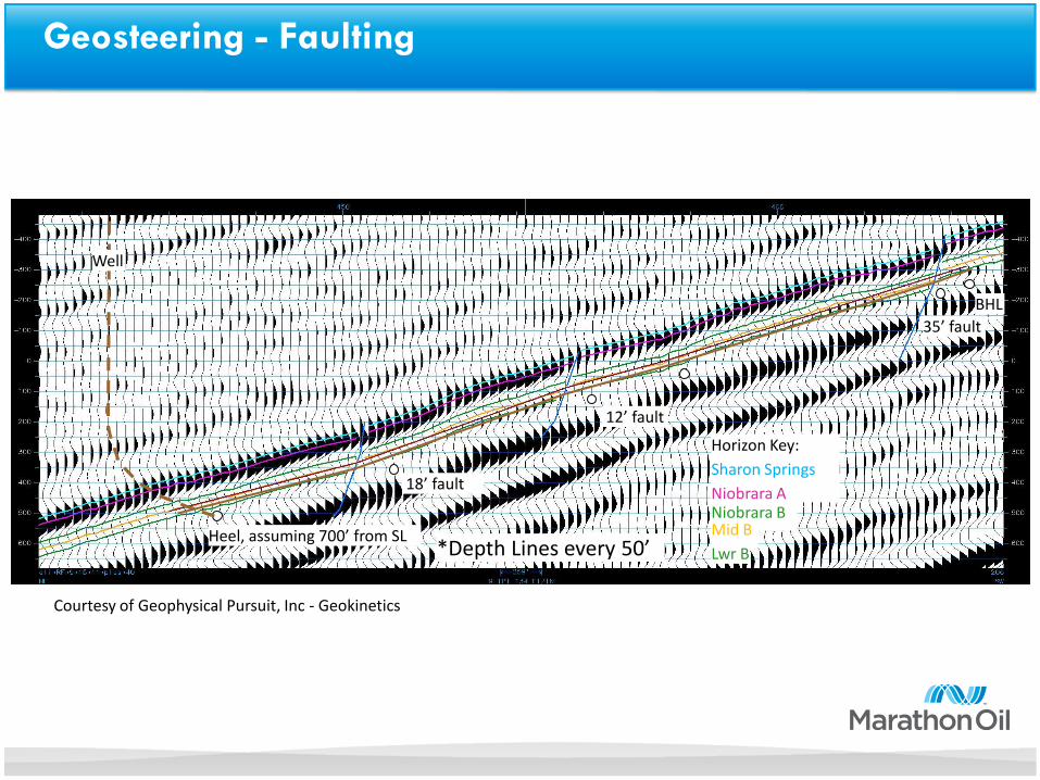
Well
Horizon Key:
Sharon Springs
Niobrara ANiobrara BMid B
Lwr BHeel, assuming 700’ from SL
18’ fault
12’ fault
35’ fault
BHL
*Depth Lines every 50’
Geosteering - Faulting
Courtesy of Geophysical Pursuit, Inc - Geokinetics

16
Geosteering - Faulting
Thrust Fault60’ of throw
Not seen on seismic
Bed dips of ~10°/100 °Wellbore incs of over 103 °
VS
MD
TVD

Where we are now
17
0
2000
4000
6000
8000
10000
12000
0 5 10 15 20 25 30 35 40 45 50
De
pth
Days
Horizontal Wells Days vs. Depth

Moving Forward
Pushing the technical limit
Implementing drilling technology/equipment
Evaluation of current contractors and service
Multi-well pads
Reducing rig move distance/time
Evaluating fracs through monitor wells –optimizing design
Deeper horizons?
18
Niobrara Resource Play
19
•Ray Steppe
•Mike Olson
•Darrell Eubanks
•Etc
Questions?