Embed Size (px)
Citation preview

- 1
User’s Manual
TWAIN Driver
Nikon Scan Windows
Contents1. Overview2. Before You Begin
2.1 System Requirements2.2 Software Installation
3. Basic Operations3.1 Launching and Quitting3.2 Main Dialog Box3.3 Basic Scanning
4. Scanning Conditions4.1 Choosing the Scanner4.2 Setting the Gamma Value4.3 Positioning Media4.4 Ejecting Film (film scanners only)4.5 Choosing the Media Type 4.6 Crop/Preview Area Buttons and Menu4.7 Cropping4.8 Crop Size Controls4.9 Autofocus (film scanners only)4.10 Adjust Focus (film scanners only)4.11 Autoexposure
5. Image Compensation5.1 Brightness / Threshold5.2 Contrast5.3 Color Balance5.4 Level Display
-

6. Gamma Curves6.1 Viewing the Gamma Curves6.2 Viewing the Histogram6.3 Modifying the Gamma Curves
7. Saving and Loading Settings7.1 Saving Settings7.2 Deleting Settings7.3 Recalling Settings7.4 Exporting Settings7.5 Importing Settings7.6 Reset Color Settings
8. Copyright Information and the About WindowAppendix A:
Features Specific to the LS-20 and LS-1000A.1 Software Interpolation
Appendix B: Features Specific to the LS-4500AFB.1 Film FormatB.2 Preview QualityB.3 Final Scan QualityB.4 SharpeningB.5 Make Shading
Appendix C:Features Specific to the AX-110 and AX-210C.1 Main Dialog BoxC.2 Using Option AdaptersC.3 Software InterpolationC.4 Sharpening
Index
- 2
Cautions• The reproduction of all or part of this manual without our
permission is prohibited.
• The information contained in this manual is subject to changewithout notice.
• We have made every effort to produce a perfect manual,but should you find any mistakes, we would be grateful if youwould kindly let us know.
• We shall take no responsibility for consequences resultingfrom the operation of this product, despite the termsmentioned above.
Trademark InformationIBM and IBM PC/AT are registered trademarks of International BusinessMachines Corporation
MS-DOS and MS-Windows are trademarks of Microsoft Corporation.
Adobe and Adobe Photoshop are trademarks of Adobe SystemsIncorporated.
All other brand or product names mentioned in this manual are thetrademarks or registered trademarks of their respective holders.
-

Notice concerning prohibition of copying orreproductionNote that simply being in possession of material which has beencopied or reproduced by means of a scanner may bepunishable by law.
• Items prohibited by law from being copied or reproduced
Do not copy or reproduce paper money, coins, securities,government bonds, or local government bonds, even if suchcopies or reproductions are stamped “Sample”.
The copying or reproduction of paper money, coins, orsecurities which are circulated in a foreign country isprohibited.
The copying or reproduction of unused postage stamps orpost cards issued by the government without obtainingapproval from the government is prohibited.
The copying or reproduction of stamps issued by thegovernment and certified documents stipulated by law isprohibited.
- 3
• Cautions on certain copies and reproductions
The government has issued cautions on copies orreproductions of securities issued by private companies(shares, bills, checks, gift certificates, etc.), commuter passes,or coupon tickets, except when a minimum of necessarycopies are to be provided for business use by acompany. Also, do not copy or reproduce passports issuedby the government, licenses issued by public agencies andprivate groups, ID cards, and tickets, such as passes and mealcoupons.
• Comply with copyright notices
The copying or reproduction of works such as books, music,paintings, woodcut prints, maps, drawings, movies, andphotographs which are copyrighted creative works isprohibited except when it is done for personal use at homeor for similar restricted and non-commercial use.
-

1. OverviewThank you for purchasing your Nikon scanner. This manualexplains how to use Nikon scanners with Nikon Scan Windowsfor IBM PC/AT or compatible computers. Please read thedocumentation thoroughly to ensure proper operation and thebest results from your scanner.
Note for Windows 95 users: The instructions in this manual arebased on the Nikon Scan Windows 3.1 version. The dialog boxesof the Windows 95 version differ from those of the Windows 3.1version.
Nikon Scan Windows conforms to the TWAIN scannerinterface specification, and provides the following functionality:
• Nikon Scan Windows supports the AX-110 (ScanTouch110) and AX-210 (ScanTouch 210) flatbed scanners and theLS-20 (COOLSCAN II), LS-1000 (SUPER COOLSCAN),and LS-4500AF film scanners. The AX-1200 flatbed scanneris not supported by Nikon Scan.
• Scanners supported by Nikon Scan can be operated bylaunching the Nikon Scan TWAIN driver from the NikonControl Windows application provided with this product.
• Scanners supported by Nikon Scan can also be operated bylaunching the Nikon Scan TWAIN driver from the acquiremenu within other applications compatible with Acquireplug-ins, such as Adobe Photoshop.
- 4
• With the optional AF-10 Auto Document Feeder mountedon the AX-110 or AX-210 or the optional SF-100 AutoSlide Feeder mounted on the LS-1000, images can beautomatically and sequentially scanned by launching thissoftware from within the Nikon Control application.Consecutive and automated scanning might also besupported by other imaging applications, but Nikon cannotensure complete compatibility.
Note: The operating procedures for the LS-20 and LS-1000 areidentical except that the LS-20 does not support the optional AutoSlide Feeder. Differences between these scanners and theLS-4500AF are described in Appendix A, Features Specific to theLS-20 and LS-1000, and Appendix B, Features Specific to theLS-4500AF. Features specific to the AX-110 and AX-210 aredescribed in Appendix C. Please be sure to read the appropriateappendix for the scanner you are using.
Note: The illustrations in this manual are based on the windowsand menus displayed when the selected scanner is the LS-1000.Depending on the scanner selected, the items displayed in NikonScan's Main dialog box and its associated menus may differ slightlyfrom those shown here. Please consult the appropriate appendixfor the scanner you are using.
-

2. Before You Begin
2.1 System Requirements
Nikon Scan Windows 3.1 version
To run Nikon Scan Windows 3.1 version, the followingminimum hardware and software is required:
• IBM PC/AT or compatible with i386SX or better• MS-DOS 5.0 or later• MS-Windows 3.1 or later• 8MB or more of RAM• 1MB or more of hard disk capacity (a 300MB or larger hard
disk is recommended)• SCSI board with ASPI driver (Adaptec 1505 and 2940 are
recommended.)• VGA (640 x 480 pixels) monitor or better• Monitor with 16.7M colors, 64K colors, 32K colors, 256
colors, 256 grayscale, 16 grayscale
- 5
Nikon Scan Windows 95 version
To run the Windows 95 version of Nikon Scan, the followingminimum hardware and software is required:
• IBM PC/AT or compatible with i386DX or better• MS-Windows 95• 8MB or more of RAM• 1MB or more of hard disk capacity (a 300MB or larger hard
disk is recommended)• SCSI board with ASPI (Adaptec 1505 and 2940 are
recommended.)• VGA (640 x 480) monitor or better• 8-bit or more of video card and monitor with 16.7M colors,
64K colors, 32K colors, 256 colors
-

2.2 Software InstallationThe Install disk provided with this product contains the NikonScan Windows TWAIN driver and the Nikon ControlWindows application.
To begin using the Nikon Scan TWAIN driver, you must firstinstall Nikon Scan, as described in the Installation section of theNikon Control manual provided with this product.
Nikon Control is easy-to-use application that acquires imagesfrom the scanner via the Nikon Scan Windows TWAIN driver.Use Nikon Control to scan a number of images consecutivelywith an optional autofeeder attachment fitted to the AX-110 orAX-210 flatbed scanners or to the LS-1000, or use it as yourbasic scanning application, if you do not have any plug-incompatible software available. The procedures for using NikonControl are covered in the Nikon Control Windows User’sManual.
- 6 -

3. Basic OperationsConnect the scanner as described in the hardware manual. Firstturn on any peripheral devices, including your scanner(s), thenturn on the PC.
If you are using a Nikon film scanner, be sure to always removethe strip film holder from the film slot before turning thescanner on.
Refer to the hardware manual provided with the product fordetails on how to insert and position the media to be scanned.
If an SCSI board has not been installed, install one as describedin the directions supplied with the board. When installing theSCSI board for the first time, be careful not to set I/Oaddresses, interrupt numbers, and DMA channels that conflictwith the I/O, interrupt and DMA settings of other cards, such asvideo graphics adapters, and so on. Before installing the SCSIboard in the PC, confirm that the PC is powered off.
3.1 Launching and QuittingThe Nikon Scan Windows TWAIN driver can be launchedfrom an imaging application, or from within Nikon Control, asdescribed in detail below.
- 7
Launching
Step 1
Start up Windows 3.1 and launch Nikon Control.
After Nikon Control is launched, the following Control paletteappears in the Nikon Control window.
-

Step 2
Select the TWAIN driver by choosing Preference… from theFile menu.
- 8
The Nikon Control Preferences window appears.
-

Select the required TWAIN driver from the TWAIN Sourcepop-up menu.
Step 3
Click the Acquire button on the Control palette, or chooseAcquire a single image from the File menu.
Acquire
- 9
The Nikon TWAIN Source window will appear.
-

QuittingClicking the Close button in the Nikon TWAIN Source windowwill return you to Nikon Control, or to your current imagingapplication.
- 10
3.2 Main Dialog BoxNikon Scan will automatically detect which scanners areconnected, and display the Main dialog items and menusappropriate for the scanner you select. (The Main dialog boxitems will vary slightly, depending on the selected scanner.)
If multiple Nikon scanners are connected and powered on, firstchoose the scanner you are going to use from the pop-upmenu at the top left corner of the Main dialog box. Onlyscanners supported by Nikon Scan will be visible in this pop-upmenu. HA is an abbreviation for “Host Adapter”, and thenumber next to it is the SCSI ID of the scanner.
Note: Depending on what devices are actually connected to yourcomputer, the options which will appear in the pop-up menu abovemay differ from those shown here.
-

- 11 -

Interactive HelpClicking the Help button at the bottom left of the windowactivates the Interactive Help function. Passing the cursor overa window item automatically displays appropriate Help text inthe message display area.
The Interactive Help display disappears when the Help button isclicked again.
- 12
Control Menu
The Control menu offers the following functions;
Restore: Restores the Main dialog box to its originalsize when it has been enlarged with theMaximize command
Move: Lets you move the Main dialog box
Size: Lets you re-size the Main dialog box
Maximize: Enlarges the Main dialog box to fill the screen
Close: Closes the Main dialog box
Switch To…: Lets you activate another window
About…: Displays the About window
-

3.3 Basic ScanningThis section gives a brief description of the standard acquisitionprocedure after the Main dialog box is displayed. The individualbuttons and menus are explained in detail in the followingchapters.
Choosing the ScannerNikon Scan will automatically detect which scanners areconnected, and display the Main dialog items and menusappropriate for the scanner you select. The Main dialog boxitems will vary slightly, depending on the selected scanner.
If multiple Nikon scanners are connected and powered on, firstchoose the scanner you are going to use from the pop-upmenu at the top left corner of the Main dialog box. Onlyscanners supported by Nikon Scan will be visible in this pop-upmenu.
Note: Depending on what devices are actually connected to yourcomputer, the options which will appear in the pop-up menu abovemay differ from those shown here.
- 13
Positioning MediaInsert or position the media to be scanned as described in yourscanner's hardware manual.
Ejecting Film (film scanners only)To eject film, click the button shown below. If you are using theoptional SF-100 Auto Slide Feeder with the LS-1000, clickingthis button will eject the current slide and set the next one. Ifyou are using the LS-4500AF, you can also eject film by pressingthe scanner's Eject button.
Media TypeChoose the media type to be scanned.
Note: The above menu may differ depending on the scanner andoptions used. Please see the appendix appropriate to the scanneryou are using.
-

PreviewClicking the Preview button starts a preview operation.
Before the preview process begins, a prescan operation will becarried out if the Prescan check box is turned on.
PRESCAN ON PRESCAN OFF
Note: Even if the prescan check box is turned on, the LS-4500AFwill not conduct a prescan operation if the cropping area has notbeen changed.
Prescan check box
- 14
If the Prescan check box is turned off when a prescan isrequired, the following indication will appear.
In this case you can carry out the prescan operation after thepreview is completed by choosing Autoexposure from theSpecial Capabilities menu.
Note: Depending on the scanner you have selected, the optionswhich appear in the pop-up menu above may differ from thoseshown here. Please see the appendix appropriate to the scanneryou are using.
This indication appears when a prescan operation has not been carried out
-

When the preview operation is completed, an image isdisplayed in the Preview display area.
- 15
CroppingUsing the mouse, click and drag a bounding box to specify arectangular crop area in the preview image display area.
Using the four buttons shown below, the image displayed in thepreview area by the preview operation can be flipped verticallyor horizontally, and enlarged or reduced.
-

Setting Size, Resolution, and Image AdjustmentYou can change settings such as the resolution, scale, contrast,gamma curve, and other parameters, as required.
- 16
ScanningWhen the Scan button is clicked, scanning is carried out inaccordance with the settings made, and the acquired image ispassed to the imaging application, or to Nikon Control.
While scanning is in progress, the following window is displayed.
Clicking the Cancel button stops scanning.
-

4. Scanning ConditionsExcept where otherwise noted, the operating procedurescovered in the present chapter are identical for all scannerssupported by Nikon Scan. Features specific to each model arecovered in Appendix A, Features Specific to the LS-20 and LS-1000, Appendix B, Features Specific to the LS-4500AF, andAppendix C, Features Specific to the AX-110 and AX-210.
- 17
4.1 Choosing the ScannerNikon Scan will automatically detect which scanners areconnected, and display the Main dialog items and menusappropriate for the scanner you select. The Main dialog boxitems will vary slightly, depending on the selected scanner.
If multiple Nikon scanners are connected and powered on, firstchoose the scanner you are going to use from the pop-upmenu at the top left corner of the Main dialog box. Onlyscanners supported by Nikon Scan will be visible in this pop-upmenu.
The names and SCSI IDs of the connected scanners are shownin the menu. HA is the abbreviation of Host Adapter, and thenumber next to it is the ID number of the SCSI board.
Note: Depending on what devices are actually connected to yourcomputer, the options which will appear in the pop-up menu abovemay differ from those shown here.
-

4.2 Setting the Gamma ValueYou can adjust the Monitor Gamma values for red, green, andblue, and the Application Gamma value.
When setting the Gamma values, choose Monitor Gamma…from the pop-up menu at the top left corner of the Main dialogbox.
- 18
The Gamma window then appears.
Meaning of the Buttons
Cancel: Discard settings and return to Main dialogbox.
OK: Save settings and return to Main dialog box.
-

Monitor GammaThe Gamma dialog box allows you to adjust the appearance ofthe preview image within Nikon Scan. Changing these valueswill not modify the actual image data obtained in a scanningoperation.
Set the gamma values for each of the red, green and bluepatches so that the outer and inner rectangles match as closelyas possible.
Red
Green
Gray
Blue
Select a value which will makethese two areas match indensity.
- 19
Setting visually matching densities for each pair of color patchesshould also result in the display of matching inner and outergray density patches. However, this may not always be thecase, depending on the monitor used. You can adjust thematch of the gray patches by changing the RGB gamma settingsagain. However, if you correct the overall density gradation thisway, the RGB color balance may no longer be optimallyrepresented on the monitor.
Adjustment range: 0.8 to 3.0
Note: The monitor gamma values entered here are only used tocorrect for the display of preview images within Nikon Scan. Asthese parameters are not used to compensate the display of finalscanned images by your host application software, nor for otherapplication software, you should adjust the monitor gamma settingsfor each application you use with Nikon Scan, with the gammacorrection tools provided by those applications.
-

Application GammaApplication Gamma stores a correction value used to processfinal scanned image data as it is passed from Nikon Scan to thehost application.
Adjustment range: 0.8 to 3.0
Note: In the Windows environment, Monitor Gamma is handledwithin individual applications, rather than globally by the operatingsystem. Adobe Photoshop provides a Calibration dialog (from thePreferences menu) to set a specific Gamma value. To displayimage data correctly within Photoshop, the image coming fromNikon Scan must first be compensated. The value entered here willprocess and adjust the image data through the scanner's 8, 10, or12-bit LUT (look-up-table), taking full advantage of the bit-depthspecification of the scanner model connected.
- 20
4.3 Positioning MediaInsert or position the media to be scanned as described in yourscanner's hardware manual.
4.4 Ejecting Film (film scanners only)To eject film, click the button shown below (this button is notdisplayed when an AX-110 or AX-210 flatbed scanner isselected). If you are using the optional SF-100 Auto SlideFeeder with the LS-1000, clicking this button will eject thecurrent slide and set the next one.
Note: With the LS-4500AF, you can also eject film by pressing thescanner's Eject button.
After the film eject button has been clicked, a prescan operationwill be carried out automatically.
-

4.5 Choosing the Media Type
Media Type SelectionChoose the type of media to be scanned.
Note: The above menu may differ depending on the scanner andoptions used. Please see the appendix appropriate to the scanneryou are using.
Choose one of the following from the upper part of the MediaType menu.
B+W Line Art: To scan black and white binary images
Grayscale: To scan grayscale images
Color: To scan color images
Choose one of the following from the lower part of the MediaType menu.
Positive: To scan positive images
Negative: To scan negative images
- 21
Filter SelectionWith some images good results can be obtained by using adifferent color filter from the default filter in grayscale scanning,and a filter selection function is provided for this purpose. Thisfunction can be used to produce grayscale and B+W Line Artscans, and is useful for ‘dropping out’ unwanted colors, such asdocument stains, etc.
If you pull down the Media Type menu while holding down theCtrl key on the keyboard, the filter selection menu will appearat the end of the Media Type menu.
Choose the filter you want to use from the menu.
-

4.6 Crop/Preview Area Buttons and MenuThe preview image acquired after clicking the Preview button isdisplayed in the crop/preview area.
- 22
Locating the cursor on the preview area and clicking the right-hand button of the mouse brings up the pop-up menu.
Using the four buttons below the preview area, or selecting theitems in the pop-up menu, the image displayed by the previewoperation can be flipped vertically or horizontally, and zoomedin or out.
Note: The pop-up menu contains the Monitor Gamma item.This function is identical to that of Monitor Gamma in the pop-upmenu at the top left corner of the Main dialog box. For detailsconcerning the Monitor Gamma setting, refer to Section 4.2.
-

Flip
The entire preview area display (including any existing cropmarquis) is flipped horizontally.
- 23
The entire preview area display (including any existing cropmarquis) is flipped vertically.
When the original image is flipped horizontally or vertically, thecorresponding Flip button appears to have been pressed, andwill remain in a depressed position, as shown below. Clickingthe button again restores its original appearance.
-
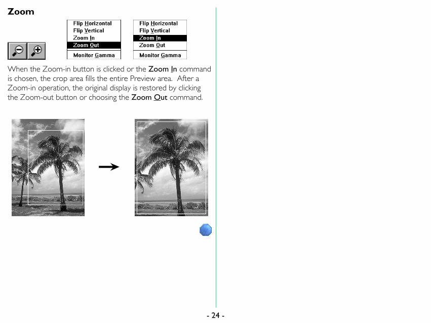
Zoom
When the Zoom-in button is clicked or the Zoom In commandis chosen, the crop area fills the entire Preview area. After aZoom-in operation, the original display is restored by clickingthe Zoom-out button or choosing the Zoom Out command.
- 24 -

4.7 CroppingYou can use your cursor in the crop/preview area, to set up anew crop, or to move or change the size of the current croparea.
Establishing a New CropAfter the preview image is displayed, locate the cursor at anystarting point on the preview (the top left is shown in theexample), and then drag the cursor to another location(bottom right in the example), thus forming a rectangle, which isreferred to as 'marquis' of 'marching ants'.
Note: ‘Dragging’ means moving the mouse while holding down themouse button.
- 25
The entire preview area can be re-selected by double-clickinganywhere in the preview window.
Note: For reasons involving the compression and display of thepreview image, there may be a slight difference between the croparea specified on the screen and the area that is actually scanned.When cropping an image, allow sufficient safety margin to ensurethat important element are not cropped out.
-

Moving the Crop AreaTo change the position of the crop rectangle, simply locate thecursor so that it is inside the frame and then drag the frame tothe desired position.
- 26
Changing the Size of the Crop AreaTo change the size of the crop area, drag a side or corner ofthe crop frame. When a side is dragged, the area will changeonly in the vertical or horizontal direction. When a corner isdragged, the size of the area will change both vertically andhorizontally. Note the type of cursor used for each change.
-

4.8 Crop Size ControlsThese controls let you set the output size, output resolution,and scale.
- 27
DimensionsThe scanned output size can be specified by entering width andheight values. If an unacceptable value is entered, it will bedisplayed in red. When the size is changed by cropping thePreview, the numbers displayed in the size value edit boxes willalso change at the same time.
The units for width and height can be selected from the pop-upmenu. When this selection is changed, the values in the boxesare converted to the equivalent new units.
Selection UnitPixels Pixel
Inches Inch
cm Centimeter
mm Milimeter
Picas Pica
Points Point
Note: If the unit is changed, the ruler and location display alsochange accordingly.
-

Cropping Coordinates
The location of the current crop is given by the absolutenumerical position of its top and left sides. The distance, inpixels, from the top to the bottom of the crop is displayed asthe pixel height, the distance from the left to the right side ofthe crop as the pixel width. These coordinates are displayed inpixels, regardless of the units selected for Width and Height(and corresponding ruler display) in the size control area.
- 28
Output ResolutionEnter the desired resolution in the “Output Resolution” field inthe dialog box in order to set the output resolution. Theresolution specified here refers to the output resolution of thescanned image; enter a value suitable for the final purpose ofthe scan.
If an unacceptable value is entered, it will be shown in red.
The units for resolution can be selected from the pop-up menu.When this selection is changed, the value in the box is convertedto the new units.
Selection UnitPixels/Inch Pixels/Inch
Pixels/cm Pixels/Centimeter
Pixels/mm Pixels/Milimeter
Pixels/Picas Pixels/Pica
Pixels/Point Pixels/Point
-

Scale‘Scale’ means the relative scale of the output resolution or size,and input resolution or size. If input and output size andresolution are the same, the scale is 100%. The Scale value canbe specified either by entering a value or by dragging the sliderwith the mouse. If an unacceptable value is entered it will beshown in red. The Scale is always shown as a percentageincrease from the original size, to the final scanned size.
Modifying the size of the crop rectangle while the width andheight aspect ratio is locked will change the Scale value, not thefinal output width and height values.
- 29
File Size and Disk SpaceThe file size and amount of free disk space are shown belowthe Scale.
Note: If the file size calculated from the size, resolution, and scalesettings is too large to be saved within the available disk space, thevalue will be highlighted in yellow.
Note: You should check the File Size and Disk Space availablebefore starting a final scan. If the required space for a scanexceeds the available space, the file size needed will be displayedin highlighted text.
Padlock IconsThe width/height aspect can be locked by clicking the padlockicon located to the left of the width and height input boxes (theicon will change from green to red when clicked). If a newvalue is entered for either width or height when the aspect ratiois locked, the other value will automatically be changed tomaintain the specified aspect ratio.
The padlock icon to the left of the File Size information itemwill lock in the file size, permitting the size and resolution tochange in proportion to each other without changing the finalquantity of scan data—the total number of pixels scanned.Locking file size simultaneously locks the width/height aspectratio.
-

4.9 Autofocus (film scanners only)The focus of the image can be adjusted by clicking theAutofocus button shown below (this button is not displayedwhen an AX-110 or AX-210 flatbed scanner is selected).
You can choose a location in the image as the focus position byclicking this button while simultaneously holding down the Ctrlkey. If you click the Autofocus button without specifying afocus position, the autofocus position chosen will be either thecenter of the image, or, if no autofocus position has beenspecified since the start of the current session, the center of thecurrent crop.
Focus position cursor
- 30
You can cancel the focus position cursor by clicking the Returnto crop button.
-

4.10 Adjust Focus (film scanners only)This function allows you to adjust focus to compensate forwarping of the film or for differences in the thickness of slidemounts.
To use the Adjust Focus function, choose Adjust Focus… fromthe Special Capabilities submenu (the Special Capabilitiessubmenu is located on the pulldown menu at the top leftcorner of the Main dialog box). The Special Capabilities menufor the AX-110 and AX-210 does not include the Adjust Focusfunction.
Note: The menu for the LS-4500AF differs from that shownabove. See Appendix B.
- 31
When the Adjust Focus function is chosen from the SpecialCapabilities submenu, the following dialog box appears.
Drag the slider or input the desired value, then click the OKbutton.
Note: The values shown at the ends of the slider bar will varydepending on the autofocus position and the scanner model. Theautofocus position always has a value of zero.
-

4.11 AutoexposureThe Autoexposure function can be used to perform a prescanafter a preview operation has been completed.
If you click the Preview button when the Prescan check box isturned off or while holding down the Ctrl key, the prescanoperation will not be carried out. In this case, you can performa prescan operation after preview by selecting Autoexposurefrom the Special Capabilities submenu.
Note: The pop-up menu shown above is for the LS-1000. Thecorresponding pop-up menus for the LS-4500AF and for theAX-110 and AX-210 are different. Please see the appendixappropriate to the scanner you are using.
The prescanning operation begins immediately on your selectingthe Autoexposure function from the Special Capabilitiessubmenu.
- 32 -

5. Image CompensationThis chapter explains how to adjust continuous tone brightness,line art threshold, contrast, and color balance. All thesesettings are made using buttons or text edit boxes. The resultsof compensation can be checked with a preview scan.
The appearance of the Main dialog box varies with the MediaType, as shown below.
Note: When a monitor with 32K colors or more is used, the R, G,and B buttons are shown in their respective colors.
Color Grayscale B&W LineArt
- 33
5.1 Brightness / ThresholdThis control is used to set the brightness for a Color orGrayscale image, or the threshold value for a B&W Line Artimage.
When this button is clicked, a slider bar pops up. The value isset by dragging the slider to the left or right while holding downthe mouse button. The same result can be achieved byentering a value directly in the box to the right of the button.
When the slider is dragged in the plus direction, the images willbe brighter and the black point will begin to float abovemaximum black. When dragged in the minus direction, theimages will become darker and dimmer.
For a B&W Line Art image, the set value is the threshold value.
Brightness adjustment range: -100 to 100
Threshold adjustment range: 0 to 255
-

5.2 ContrastThis control is used to set the contrast for Color or Grayscaleimages. A contrast setting is not used for B&W Line Artimages.
When this button is clicked, a slider bar pops up. The value isset by dragging the slider to the left or right while holding downthe mouse button. The same result can be achieved byentering a value directly in the box to the right of the button.
When the slider is dragged in the plus direction, the black pointand white point input values will be restricted, thus steepeningthe tone curve and producing punchier images with lessgradation subtlety. When dragged in the minus direction, theblack output values will be raised and the white point outputvalues lowered, thus flattening the tone curve and producingflatter images with more gradation subtlety.
Adjustment range: -100 to 100
- 34
5.3 Color BalanceThe color balance is adjusted using three controls for Red,Green, and Blue. These three controls only appear when'Color' has been set for the Media Type.
When one of these buttons is clicked and held down, a sliderbar pops up. The value is set by dragging the slider to the leftor right while holding down the mouse button. The same resultcan be achieved by entering a value directly in the box to theright of the button.
You can adjust overall color balance by emphasizing or de-emphasizing each of the three primary colors of the scan.Unlike brightness compensation, in which the amount of theRed (R), Green (G), and Blue (B) components in the image arechanged simultaneously, affecting the brightness of the image asa whole, color balance adjustment permits individualcompensation for each of these colors.
Adjustment range: -100 to 100
-

5.4 Level Display
RGB values or CMY percentages at the cursor position aredisplayed while the cursor is over the crop/preview area. Thevalues can be switched between absolute RGB pixel values (in8-bit level equivalent) and CMY percentages, by clicking withinthe boundary surrounding the density display area.
For grayscale images, the L (luminance in 8-bit levelequivalence) or K (the black density percentage) value at thecursor position is displayed.
- 35 -

6. Gamma CurvesSelective gamma curve editing is essential for the highest-qualityscanning. In many cases, the factory default gamma curves willyield excellent results. These default gamma curves are wellsuited to the widest variety of original media. However, undercertain circumstances, you may want to use other gammacurves.
- 36
6.1 Viewing the Gamma CurvesWhen the Media Type is ‘Color’, four gamma curves aredisplayed.
-

When the Media Type is ‘Grayscale’, only one gamma curve isdisplayed.
- 37
When the Media Type is set to ‘Color’, you can edit one mastercurve and three primary curves, i.e., for Red, Green, and Blue.When the Media Type is set to 'Grayscale', you can edit agrayscale curve only.
Each of the Red, Green and Blue gamma curves is unique. Themaster curve provides a simple means of adjusting all of theprimary curves equally. Thus, you do not have to adjust eachprimary curve individually.
This two-dimensional graph represents the input/output transferfunction. The horizontal axis represents the input, or originalgamma levels. The vertical axis represents the output, or newgamma levels.
A diagonal line connecting the lower-left and upper-rightcorners would represent a linear transfer function. Forexample, an input value of 100 would produce an output valueof 100. Similarly, an input value of 200 would produce anoutput value of 200, and so on. A horizontal line running alongthe bottom border would map all inputs into a zero output,consequently creating a black image. A line beginning at the topleft corner, and ending in the bottom right corner, wouldproduce a negative image.
-

6.2 Viewing the HistogramAt times it may be useful to view the histogram of the previewimage. A histogram is a statistical representation of thedensities in an image. A histogram will be displayed when theHistogram button is clicked and held. This control is activewhen either Grayscale or Color is selected as the Media Typein the Main dialog box.
The histogram will be displayed as long as the button is helddown.
- 38
The histogram’s horizontal axis represents the pixel intensity orbrightness, the darker values appearing on the left and thelighter values on the right. The vertical axis is a statisticalrepresentation of the number of occurrences of each pixelvalue over the entire image. The histogram thereforerepresents a graphical and statistical view of the overallbrightness of an image.
-

6.3 Modifying the Gamma CurvesModifying the gamma curves is relatively easy, but modifyingthem correctly is not. While the effects of altering the mastercurve are straightforward, the relationships between the Red,Green and Blue gamma curves are far more complex, and muchmore difficult to control.
The gamma curves can be modified manually or automatically.The manual mode involves moving points on the gamma curveswith the mouse, thereby graphically reshaping the curve.
Specifying the Gamma CurveTo the right of the graph are four buttons—from top tobottom, the Master Curve button, and the Red, Green, andBlue Curve buttons. The Grayscale Curve button appears onlywhen the Media Type is set to Grayscale.
When one of these buttons is clicked, the gamma curvecorresponding to that button is selected for editing. This modeis maintained until another button is clicked.
Curva maestra
Rojo
Verde
Azul
- 39
Graphically Altering the Gamma CurvesThe individual gamma curves in the gamma curve window canbe manually altered by clicking the mouse at points on thegamma curve and dragging, thus reshaping the curve.
You will notice that changes to the shape of the gamma curveswill cause corresponding changes to the tonal quality of thedisplayed image, as seen in the preview window. As the curveis altered, a curve-fitting software algorithm redraws the newcurve.
-

Forcing the Gamma Curves to LinearTo reset curves to a linear state, clicking the Linear buttonshown below 'forces' whichever gamma curve is active to linear.Ctrl-clicking the Linear button will force all three gamma curvesto linear.
Choosing the Reset Color Controls command from theSettings menu will force the master, Red, Green, and Bluegamma curves to linear, and brightness and contrast, R, G, and Badjustment values to zero.
- 40
Setting the Black PointThe Black Point represents the darkest point in the image.Since the density range of the original media might exceed thedynamic range of the scanner, the scanner’s tonal range needsto be used as efficiently as possible. The Black Point is typicallyselected so that all values in the image that are darker than thispoint can be mapped, or converted to black without affectingthe quality of the image.
For example, suppose that the darkest area within the image,that you know to represent a true black, has a value of 10 in thescanned data. Values 0–9 would be wasted since no pixel inthe image would have a value lower than 10. By setting theBlack Point to 10, the data would be re-mapped so that a valueof 10 from the scanner would produce a 0. All the data valueswould then be meaningful.
To set the Black Point, click the Black Point button.
-

After the Black Point button is clicked, position the mousecursor over the image in the preview window and select a pixelvalue to be used as the darkest point in the image. Watch thePixel Value display closely as you move the cursor across theimage to enable you to choose the right value to modify. If youare unsure, then zoom in on the area of interest to enhance thedetail and increase the accuracy of your selection.
Black Point eyedropper cursor
- 41
The pixel you select will become the new Black Point, or refer-ence point for maximum black (often called ‘dmax’, for ‘maxi-mum density’). When the Black Point is selected, the activegamma curve is automatically adjusted to reflect this selection.This tool can be used with any gamma curve, although it is mosteffective when used with the master gamma curve, as it pro-vides a ‘neutral’ black point, which is normal for many images.
New Black Point
When you decide on the pixel you want to use as the BlackPoint of the image, clicking the mouse forces the gamma curvesto use this value as the minimum value in the preview window.Any pixels darker than the black point will be set to the mini-mum value. The result of this new curve is approximated in thepreview window. Observe the increase in contrast, and alsothe reduced White Point, covered in the next section.
-

The Black Point cursor can be restored to its ‘cropping’ state,from the ‘eyedropper’ state, by clicking the Return to Cropbutton.
- 42
Setting the White PointThe White Point represents the lightest point in the image, thusproviding a function opposite to that of the Black Point. Likethe Black Point, however, selection of a White Point reducesthe tonal range of the scanner so as not to waste any of itstonal range on light areas that are not actually present in theoriginal.
The White Point is typically selected so that all values in theimage that are lighter than this point can be mapped, orconverted to white without affecting the quality of the image.
To set the White Point, click the White Point button.
-

After the White Point button is clicked, position the mousecursor over the image in the preview window and select a pixelvalue to be used as the lightest point in the image. Watch thePixel Value display closely as you move the cursor across theimage to enable you to choose the right value to modify. If youare unsure, then zoom in on the area of interest to enhance thedetail and increase the accuracy of your selection.
White Point eyedropper cursor
- 43
When you decide on the pixel you want to use as the WhitePoint of the image, clicking the mouse forces the gamma curvesto use this value as the maximum value in the preview window.Any pixels lighter than the White Point will be set to the maxi-mum value. The result of this new curve is approximated in thepreview window.
The pixel you select will be mapped to the new White Point, orreference point for maximum lightness, (often called ‘dmin’, for‘minimum density’). When the White Point is selected, theactive gamma curve is automatically adjusted to reflect thisselection. This tool can be used with any gamma curve,although it is most effective when used with the master gammacurve, as it provides a ‘neutral’ white point, which is normal formany images.
New White Point
-

The White Point cursor can be restored to its ‘cropping’ state,from the ‘eyedropper’ state, by clicking the Return to Cropbutton.
- 44
Automatic Contrast AdjustmentIf you prefer, the Nikon Scan TWAIN driver is capable ofselecting optimal neutral Black and White Points for you. TheAutomatic Contrast Adjustment control in the TWAIN driverwill usually produce excellent results. Simply click the ContrastAdjust button.
The software will analyze the portion of the preview imagecontained within the cropped region of the preview, andautomatically select an optimum Black Point and White Point.The active gamma curves will be modified automatically.
Note that this may sometimes lead to undesirable colorbalance. If for example, the original image is of a predominantly‘warm toned’ scene, such as a sunset, then the neutral highlightproduced by Autocontrast, or the White point eyedropper,would be too ‘cold’ for the subject matter of the image.
-

7. Saving and Loading SettingsUsing the Settings pop-up menu, you can save the settings youhave made, or load previously saved settings. This may beconvenient for repetitive scanning at particular crops andresolutions, or when using a complex gamma correction toimprove reproduction.
- 45
Settings include the following items:
• Scanner selection, media type, width and height units, widthvalue, height value
• Aspect and file size locked/unlocked status, output resolutionvalue, magnification value
• Master, R, G, and B curves, brightness and contrast, R, G, andB adjustment values
• Orientation, horizontal and vertical flip status, help ON/OFFstatus, crop area size and location
-

7.1 Saving SettingsYou can save the current Main dialog box settings in theSettings menu of Nikon Scan.
When Save… is chosen from the Settings menu, the SaveSettings window appears to let you name the new settings.
When you enter a name and click the Save button, the settingsare saved in the system under that name.
- 46
If settings have previously been saved using the entered name,the following dialog box will appear when you click the Savebutton.
If you want to overwrite the previous settings, click the Yesbutton. If you want to keep the previous settings, click the Nobutton and enter a different name for saving the new settings.
If you pull down the Settings menu after performing the save,you will see that the name under which the settings were savedto the system has been added at the end of the menu. If thereare a number of settings, the names of all the settings aredisplayed.
-

7.2 Deleting SettingsYou can delete saved settings using Delete Settings function.
When Delete… is chosen from the Settings menu, the DeleteSettings window appears to let you specify the name to bedeleted.
To delete the settings, choose the names to be deleted andclick the Delete button. You can delete more than one settingat a time.
When the settings are deleted, the name displayed at the endof the Settings menu is also deleted.
- 47
7.3 Recalling SettingsSettings saved in the system include factory default settings andlast session settings as well as user settings.
Factory Defaults are set when the product is shipped, andcannot be changed or deleted.
Last Session settings are saved automatically when you quit theprogram. Last Session settings cannot be deleted.
You can recall Factory Defaults, Last Session settings, or settingssaved with the Save Settings function. These are displayed atthe end of the Settings menu.
When you choose the settings to be recalled, those settings areimmediately loaded into the Main dialog box.
Note: Last Session will not be displayed on the first use afterinstallation.
-

7.4 Exporting SettingsYou can save the current Main dialog box settings to a file usingthe Export Settings function. Unlike the Save… function, whichsaves settings in the system, the Export Settings function savesthem to a file that can be located anywhere you can navigate tousing the standard file dialog box. A file to which settings havebeen saved using the Export Settings function can be read usingthe Import Settings function.
To save the current settings to a file, choose Export… from theSettings menu. We recommend that you save your ‘missioncritical’ settings data using Export….
- 48
The Export Settings window appears when Export… isselected.
When you click the OK button after specifying the drive anddirectory to be saved to, and entering the file name, the currentsettings are saved to that file.
-

7.5 Importing SettingsUsing the Import Settings function, you can read the contents ofa file saved with the Export Settings function into the Maindialog box.
To read the contents of a file, choose Import… from theSettings menu.
The Import Settings window will then appear.
When you click the OK button after opening the directorycontaining the settings and specifying the file, the contents ofthat file are read.
- 49
7.6 Reset Color SettingsYou can reset the modified gamma curves and image compen-sation.
Choosing the Reset Color Controls command from theSettings menu will force the master, Red, Green, and Bluegamma curves to linear, and brightness and contrast, R, G, and Badjustment values to zero.
-

8. Copyright Information and the
About Window
Copyright Information
When Copyrights… is chosen from the Special Capabilitiesmenu, the Copyrights window appears.
The Copyrights window disappears when the Cancel button isclicked.
- 50
About Window
When About… command is chosen from the Control menu,the About window appears.
The About window disappears when the Close button isclicked.
-

Appendix A: Features Specific to
the LS-20 and LS-1000Except that the LS-20 does not support the optional SF-100Auto Slide Feeder, the operating procedures for the LS-20 andLS-1000 are identical. This following section describes featuresspecific to the LS-20 and LS-1000.
A.1 Software InterpolationSoftware Interpolation is used to provide precise image scalingand resolution.
- 51
When Software Interpolation… is chosen from the SpecialCapabilities menu, the Software Interpolation window appears.
You can choose any one of the following from this window.
Bilinear: Interpolation with emphasis on accuracy
Nearest Neighbor:Interpolation with emphasis on high-speedprocessing
None: No interpolation is performed
-

Appendix B: Features Specific to
the LS-4500AFThe following sections describe features specific to the LS-4500AF.
B.1 Film FormatThe film format to be scanned can be chosen from the MediaType menu. Resolution, maximum scanning area, and prescanarea are automatically altered to reflect the format selected.
- 52
Choose any one of the following from the menu above.
Lores: Uses the low resolution (1000 x 2000 dpi)optical system
Hires: Uses the high resolution (3000 x 3000 dpi)optical system for 35mm film using a singleframe holder
4"x5": 4˝ x 5˝ film (low resolution)
6x6--9: Film measuring from 6 x 6 to 6 x 9 (lowresolution)
6x4.5: 6 x 4.5 film (low resolution)
35mm: 35mm film (high resolution)
-

B.2 Preview QualitySetting Preview Quality allows you to choose whether previewoperations are to be performed in high speed or high qualitymode.
Select one of the following from the Preview Quality submenu.
Highest Speed: Preview with emphasis on speed
Normal: Normal preview
Highest Quality: Preview with emphasis on quality
- 53
B.3 Final Scan QualitySetting Final Scan Quality allows you to choose whetherscanning is to be performed in high speed or high quality mode.
Select one of the following from the Final Scan Qualitysubmenu.
Highest Speed: Scan with emphasis on speed
Normal: Normal scan
Highest Quality: Scan with emphasis on quality
Under normal circumstances the best choice is Highest Quality.
-

B.4 SharpeningIt is often necessary to sharpen images prior to reproductionsince there are usually losses in definition when going to press.To enhance edge contrast, choose Sharpening… from theSpecial Capabilities menu.
- 54
The Sharpening window appears.
Choose one of the following from the Sharpening window.
• Sharpen More• Sharpen• None• Blur• Blur More
-

B.5 Make ShadingAfter replacing the lamp, you must perform lamp calibrationusing the Make Shading function before you can operate thescanner (to replace the lamp, follow the directions given in theLS-4500AF hardware manual).You must use this function whenever you replace the lamp.
Note: The film holder must be ejected before this function is used,as otherwise lamp calibration will not proceed correctly.
The pop-up menu at the top left corner of the Main dialog boxincludes the Special Capabilities submenu. The Make Shadingfunction is executed immediately on your selecting MakeShading from the Special Capabilities submenu.
- 55 -

Appendix C: Features Specific to
the AX-110 and AX-210The following sections describe features specific to the AX-110and AX-210 flatbed scanners. The operating procedures forthe two models are identical.
- 56
C.1 Main Dialog BoxThe Main Dialog Box for the AX-110 and AX-210 is shownbelow.
Note that the Main dialog box for flatbed scanners does notinclude an Eject Film or Autofocus button, and that the rulers inthe Preview area differ from those shown for film scanners inscale and point of origin.
-

C.2 Using Option AdaptersWhen the optional transparency adapter or ADF (AutoDocument Feeder) is fitted to the AX-110 or AX-210, asubmenu is added to the Media Type Selection menu to enablethe option.
- 57
Using the Transparency AdapterWhen the optional transparency adapter is fitted to the AX-110 or AX-210, additional items appear at the bottom of theMedia Type pop-up menu.
Choose one of the following from the lower part of the MediaType menu.
Transparency: To scan transparency images
Reflective: To scan reflective images
Note: When scanning transparencies with the Media Type set toNegative, the prescan operation will be optimized for the currentlyselected crop. If a new crop is selected after preview, it may benecessary to carry out the prescan operation again. After changingthe crop area, it is recommended that you click the Zoom-in buttonto conduct a preview with the prescan optimized for the new crop.
-

Using the ADF (Auto Document Feeder)When the optional ADF (Auto Document Feeder) is fitted tothe AX-110 or AX-210, the ADF submenu appears at thebottom of the Media Type menu.
Choose any one of the following from the ADF submenu.
ADF Off: Disables the ADF. The document positionedon the document setting glass will be scanned.
ADF On US Letter:Enables scanning of letter-sized documentsplaced on the ADF.
ADF On US Legal:Enables scanning of legal-sized documentsplaced on the ADF.
- 58
Note: When the AF-10 Auto Document Feeder is attached toyour scanner, automated continuous scanning is available withapplications supporting continuous acquire, such as Photoshopversions 3.0 or later or EasyPhoto 1.5. Continuous scanning can beinitiated by pressing the Crtl button + the Scan button on themain dialog of Nikon Scan.
-

C.3 Software InterpolationSoftware interpolation is used to provide precise image scalingand resolution.
The pop-up menu at the top left corner of the Main dialog boxincludes the Special Capabilities submenu. Choose SoftwareInterpolation… from the Special Capabilities submenu.
- 59
The Software Interpolation window appears.
You can choose either of the following from the SoftwareInterpolation window.
Bilinear: Interpolation with emphasis on accuracy
Nearest Neighbor:Interpolation with emphasis on high-speedprocessing
-

C.4 SharpeningIt is often necessary to sharpen images prior to reproductionsince there are often losses in definition when going to press.To enhance edge contrast, choose Sharpening… from theSpecial Capabilities submenu.
- 60
The Sharpening window appears.
Choose any one of the following from the Sharpening window.
• Sharpen More• Sharpen• None• Blur• Blur More
-

IndexAAbout command 12About window 50Acquire a single image
command 9Acquire button 9Adjust Focus 31Adobe Photoshop 4, 58AF-10 Auto Document Feeder
4, 6, 58Application Gamma 20Auto Exposure 14, 32Auto Slide Feeder 4, 20Autofocus 30Automatic Contrast Adjust-
ment 44AX-110 4, 6, 56–60AX-1200 4AX-210 4, 6, 56–60
BB+W Line Art 21, 33Basic Operations 7Basic Scanning 13Bilinear 51Black Point button 40Black Point eyedropper cursor
41Blue Curve button 39Brightness 33
CChanging the Size of the
Crop Area 26Choosing the Media Type 21Choosing the Scanner 13, 17Close button 10Close command 12CMY percentages 35Color 21, 33Color Balance 34Contrast 34Control menu 12COOLSCAN II. See LS-20Copyright Information 50Copyrights command 50Copyrights window 50Crop Size Controls 27Crop/Preview Area Buttons
and Menu 22Cropping 15, 25–26Cropping Coordinates 28
DDelete command 47Delete Settings window 47Deleting Settings 47Dimensions 27
EEjecting Film 20Establishing a New Crop 25Export command 48Export Settings window 48Exporting Settings 48
- 61
FFactory Defaults 47File Size and Disk Space 29Film Format 52Filter Selection 21Final Scan Quality 53Flip buttons 23Focus position cursor 30Forcing the Gamma Curves
to Linear 40
GGamma Curves 36Gamma window 18Graphically altering the
gamma curves 39Grayscale 21, 33Green Curve button 39
HHeight 27Histogram button 38
IImage Compensation 33Import command 49Import Settings window 49Importing Settings 49Interactive Help 12
-
LLast Session 47Launching 7Level Display 35Linear button 40LS-1000 4, 6, 20, 51LS-20 4LS-4500AF 4, 14, 20, 52–55
MMain Dialog Box 10Make Shading 55Master Curve button 39Maximize command 12Media type 13Media Type Selection 21Modifying the Gamma
Curves 39Monitor Gamma 19Monitor Gamma command
18Move command 12Moving the Crop Area 26
NNearest Neighbor 51Negative 21Nikon TWAIN Source window
9

PPadlock Icons 29Positioning Media 13, 20Positive 21Preferences command 8Preferences window 8Prescan check box 14Prescan operation 14–15Preview button 22Preview Quality 53
QQuitting 10
RRecalling Settings 47Red Curve button 39Reset Color Settings 49Restore command 12Return to Crop button 42, 44RGB pixel values 35
SSave command 46Save Settings window 46Saving and Loading Settings
45Saving Settings 46Scale 29Scan button 16Scanning 16Scanning Conditions 17ScanTouch 110. See AX-110ScanTouch 210. See AX-210Setting Media 13
Setting size, resolution, andimage adjustment 16
Setting the Black Point 40–42Setting the Gamma Value 18Setting the White Point 42–44Settings pop-up menu 45SF-100 4, 20Sharpening 54, 60Sharpening window 54Size command 12Software Installation 6Software Interpolation 51, 59Software Interpolation com-
mand 51Software Interpolation win-
dow 51Specifying the Gamma Curve
39Strip film holder 7SUPER COOLSCAN. See LS-
1000Switch To command 12System Requirements 5
TThreshold 33Transparency Adapter 57TWAIN 4TWAIN Source pop-up menu
9
VViewing the Gamma Curves
36Viewing the Histogram 38
- 62
WWhite Point button 42White Point eyedropper
cursor 43Width 27Windows 95 4, 5
ZZoom-in button 24Zoom-out button 24
-


![Instrukcja PL - Nikon SB800 [scan]](https://img.dokumen.tips/doc/110x75/5571f24649795947648c6926/instrukcja-pl-nikon-sb800-scan.jpg)
