Embed Size (px)
Citation preview

B
B
B
B
This is a model of the War
Nigel Lawton 009 14mm or 16.5mm gauge O-14 or O-16.520HP WDLR Simplex Locomotive Kit
Department Light Railways 20HP Simplex petrol-mechanical locomotive which were used to supply the trenches during WW1 and later in a wide range of industrial situations. Complete kit including two motors, reduction drives, wheels, pickups, loco body and chassis comprising resin castings, etched brass & nickel-silver & machined parts. Requires 140C & standard (180C or 240C) solder, cyanoacrylate glue and paint to complete. Couplings and driver not included.
BBBBBBBBBBBBBBBBBBBBBBBBBBBB
AA
B1
B2
B3 B4 B4
B5
B5
B6
B7
B7
B8
B8
B9 B9
B11
B12 B12 B12
B13 B14 B13 B14
B15 B15 B15
B17 B17
B17
B16 B16 B16
B18
B19
B20
B20
B21
B22 B22
B23
B25
B24
B26
B27
B28
B28
B29 B30
B30
B30
B31
B32
B33
B33
B34
B34 35
35
35
B36
B37
B38
B11
B39 B39 B40
B10
B31
Body etched brass component identification
Features independently motorised radiator fan
http://www.nigellawton009.com
1) Upper frame. 2) Side frame engine side. 3) Side frame gearbox side. 4) Lower frames. 5) Cross member & driver platform. 6) Bonnets (hoods) top and sides. 7) Bonnet ends 8) Cross member (radiator end). 9) End frames 10) Frame end pieces 11) Bonnet power bulge. 12) End overlay left 13) End overlay centre brake end. 14) End overlay centre radiator end 15) End overlay right 16) Side overlay left 17) Side overlay right 18) Frame overlay 19) Engine overlay 20) Gearbox overlay 1 21) Gearbox overlay 2 22) Radiator bars 23) Radiator flange (optional) 24) Radiator bracket 1 (optional) 25) Radiator bracket 2 (optional) 26) Fan box (optional) 27) Fan 28) Sand boxes
B29) Seat base B30) Seat back B31) Seat top B32) Brake column B33) Brake wheel B34) Bonnet hinge B35) Buffer B36) Clutch pedal top B37) Clutch pedal bottom B38) Number plate B39) Exhaust bracket (optional) B40) Hose strap

Chassis etched N/S component identification
Each 20HP WD Simplex loco kit is made up from the following parts:- A) Nickel-Silver chassis etch B) Brass body etch C) M3 x 20mm spacers x 2 D) M3 c/s screws x 4 E) M2 brass cheesehead screw x 1 F) M2 brass nut G) Ø10mm x 12mm motor H) 150 ohm resistor. I) 1.1mm root/2.1mm OD pulley x 2 J) M2.5 nylon nut & bolt & metal washer x 1 K) 1mm to 1.5mm shaft adapter x 1 L) 5mm root/6mm OD pulley M) Tenshodo worm gear sets x 4 N) 1.5mm shafting x 30mm O) 1.5mm to 2mm shaft adapter x 4 P) 1.7mm root/2.7mm OD pulley x 1 Q) 1.5mm ID top hat bearings x 4 R) 10.5mm external journal wheelsets x 2 S) 15 ohm resistor T) 6.5mm ID 0.6mm cross-section drive belts x 2 (1 spare) U) 0.8mm PCB material 12mm x 6mm V) 0.5mm x 30mm phosphor-bronze strip W) 1.5mm shafting x 19mm x 2 X) Radiator resin casting Y) Exhaust resin casting Z) 6mm x 10mm motor Æ) 6.5mm diameter drive belt x 2 (1 spare) Ø) 7.5mm diameter drive belt x 2 (1 spare)
A Nigel Lawton 009 Simplex Chassis V26 7mmA1) Main frame mechanism side A2) Main frame removable side A3) Main drive motor mount A4) Fan drive motor mount A5) Mechanism cross piece A6) Washers A7) Thin washers A8) Suspension overlay A9) Axle box overlay A10) Main drive motor strap A11) Fan drive motor strap A12) Fan drive worm bracket
(note this part mounts on the body)
A2
A3
A4
A8
A6 A7
A8
A8
A5
A9 A9
A8
A8
A12
A11
A10 A10
A6
A
1
A4

Nigel Lawton 009 7mm Scale 20HP WD Simplex Petrol Mechanical Loco Kit
Assembly Instructions
WARNING! ETCHED PARTS CONTAINED IN THIS KIT HAVE SHARP POINTS, EDGES AND CORNERS. HANDLE ALL ETCHED PARTS WITH CARE AND REMOVE SHARP EDGES FROM THE COMPLETED MODEL.
• PLEASE READ ALL THESE INSTRUCTIONS THROUGH BEFORE STARTING TO BUILD THE KIT. • IT IS IMPLICIT THAT ALL JOINING PIECES ETC SHOULD BE REMOVED FROM ETCHED COMPONENTS BEFORE ASSEMBLY. • THIS KIT CONTAINS MANY SMALL PARTS. PLEASE TAKE CARE NOT TO LOSE THESE PARTS. SOME SPARES ARE PROVIDED
WITHIN THE FRETS IN CASE OF LOSS AND FURTHER REPLACEMENTS ARE AVAILABLE BY MAIL INITIALLY FOR POSTAL COSTS ONLY.
• NOTE THAT NOT ALL HALF ETCHED LINES IN THIS KIT ARE FOLD LINES, CHECK THE INSTRUCTIONS BEFORE FOLDING!
Tools Required Consumables Required Standard 240 degree solder 140 degree detail solder Flux (I recommend a paste type like ‘Powerflux’) Non-permanent thread lock (e.g. Blue Loctite 242or green 603) Cyanoacrylate (‘super’ glue) Model oil
Small hobby knife or scalpel with new blade. Soldering iron (preferably temperature controlled) Flat thin nosed pliers long and short for folding, also a folding jig is nice to have but not essential. Small and larger round nosed pliers Side cutters or snips for stripping wires Small needle files for cleaning up parts. Tapered Jeweller’s broaches A range of drill bits with pin vice(s). Mini drill with diamond disk or slitting disk and burrs.
General Assembly Notes Cutting parts from the frets. Use a sharp knife or scissors or special fret scissors. Apply knife side to side, not downwards. Where possible cut the trace at the opposite end to where it joins the part and trim with scissors afterwards. Use fine needle files or toolmakers stones to clean up small projections. Solder, use of flu, tinning & glue I recommend the use of 140C solder for most of the chassis, and cyano/superglue for the body and the majority of the detail parts. Using 140C solder enables only a small area of the kit to be heated and the heat-up and cool down times are much shorter. Always apply a small amount of flux before applying or re-flowing solder. To tin parts apply a small amount of flux then carry a very small amount of solder to the part with the soldering iron. Repeat if more solder is needed, but use the minimum amount to coat the surface in the thinnest possible layer. If too much is applied use the iron to take this elsewhere on the fret (to other parts needing to be tinned or onto fluxed frame areas). The whole kit can be soldered if desired with the exception of the resin cast radiator and exhaust, but will require a powerful soldering iron or blowtorch and is not advised.
Chassis Note that these instructions are available as a PDF file on my website www.NigelLawton009.com and that if you view the PDF file on your PC you can zoom in on the photos to see small details not so apparent on a printout.
Rewe1
Lbg
Ros
emove the main frame mechanism side A1 from the fret. This has double fold-back sections at both ends. These should be folded with the hald tched groove on the outside of the fold. Fold the outer part at one end back 180º and the inner part also through 180º in the opposite direction ith is half etched groove on the outside of the fold as before. Repeat with the other end. You should now have three thicknesses of material at ach end. Solder in place taking care to hold the folded parts down whilst the solder sets. Make sure that you have three thicknesses (about 1.1-.2mm) and no more.
1
Photo does not show bearings
oriention for assembly – see
right
ocate the top hat bearings Q and take two of these from the bag. Using a broach or tapered reamer open out the two bearing holes so that the earings are a snug fit. The larger diameter ‘brim’ of the bearing goes on the inside of the frame which is the side with remaining half etched rooves. Solder in place. Fold up the two tabs, one large with slot and one small, through 90º. Run a fillet of solder along the inside of these folds.
emove the main frame removable side A2 from the fret. This has single fold-back sections at both ends. Fold these with the half etched groove n the inside as for A1. Solder in place, ream out the bearing holes and fit the bearings as for A2. Fold the two small tabs and solder as for the mall tap on A1.
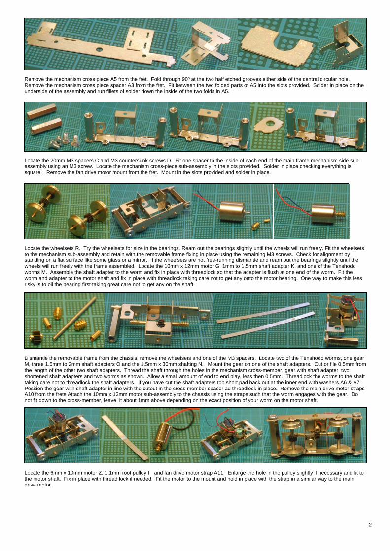
Remove the mechanism cross piece A5 from the fret. Fold through 90º at the two half etched grooves either side of the central circular hole. Remove the mechanism cross piece spacer A3 from the fret. Fit between the two folded parts of A5 into the slots provided. Solder in place on the underside of the assembly and run fillets of solder down the inside of the two folds in A5.
Locate the 20mm M3 spacers C and M3 countersunk screws D. Fit one spacer to the inside of each end of the main frame mechanism side sub-assembly using an M3 screw. Locate the mechanism cross-piece sub-assembly in the slots provided. Solder in place checking everything is square. Remove the fan drive motor mount from the fret. Mount in the slots provided and solder in place.
Locate the wheelsets R. Try the wheelsets for size in the bearings. Ream out the bearings slightly until the wheels will run freely. Fit the wheelsets to the mechanism sub-assembly and retain with the removable frame fixing in place using the remaining M3 screws. Check for alignment by standing on a flat surface like some glass or a mirror. If the wheelsets are not free-running dismantle and ream out the bearings slightly until the wheels will run freely with the frame assembled. Locate the 10mm x 12mm motor G, 1mm to 1.5mm shaft adapter K, and one of the Tenshodo worms M. Assemble the shaft adapter to the worm and fix in place with threadlock so that the adapter is flush at one end of the worm. Fit the worm and adapter to the motor shaft and fix in place with threadlock taking care not to get any onto the motor bearing. One way to make this less risky is to oil the bearing first taking great care not to get any on the shaft.
Dismantle the removable frame from the chassis, remove the wheelsets and one of the M3 spacers. Locate two of the Tenshodo worms, one gear M, three 1.5mm to 2mm shaft adapters O and the 1.5mm x 30mm shafting N. Mount the gear on one of the shaft adapters. Cut or file 0.5mm from the length of the other two shaft adapters. Thread the shaft through the holes in the mechanism cross-member, gear with shaft adapter, two shortened shaft adapters and two worms as shown. Allow a small amount of end to end play, less then 0.5mm. Threadlock the worms to the shaft taking care not to threadlock the shaft adapters. If you have cut the shaft adapters too short pad back out at the inner end with washers A6 & A7. Position the gear with shaft adapter in line with the cutout in the cross member spacer ad threadlock in place. Remove the main drive motor straps A10 from the frets Attach the 10mm x 12mm motor sub-assembly to the chassis using the straps such that the worm engages with the gear. Do not fit down to the cross-member, leave it about 1mm above depending on the exact position of your worm on the motor shaft.
Locate the 6mm x 10mm motor Z, 1.1mm root pulley I and fan drive motor strap A11. Enlarge the hole in the pulley slightly if necessary and fit to the motor shaft. Fix in place with thread lock if needed. Fit the motor to the mount and hold in place with the strap in a similar way to the main drive motor.
2

Remove four of the suspension overlays from the fret. Glue to the chassis in the locations shown. Spares provided on the fret in case of error. Remove four of the axle box overlays from the fret. Fold up as shown, one rivet on the thin section should be central on the full thickness circle. Fit to the chassis where shown. Line up the circular full thickness section with the functional wheel bearings. Take care not to get any glue into the functional wheel bearings.
LPt
FAN DRIVE
FOR BASIC WIRING: Solder the two dropper resistors to their respective motor brackets and connect the blue/black wires from each motor. Connect the red wires to the pickup. The motors are isolated from their connection wires so DCC can be easily fitted. Chassis is one side of the track and pickup the other. Several other possible wiring schemes exist, email me to discuss.
This sub-assembly mounts on the body, complete the body before building this part of the chassis. Remove the fan drive worm bracket A12 from the fret. Fold up into a box with the half etched grooves on the inside of the folds. Solder together at the join. Locate one of the 19mm lengths of 1.5mm shafting W, the 1.7mm root pulley P, one Tenshodo worm gear M and one 1.5mm to 2mm shaft adapter O. Drill a 0.8mm hole through the shaft adapter at one end to allow threadlock to be introduced once assembled. Fit the gear onto the shaft adapter. Fit the 1.7mm root pulley onto one end of the shafting. Feed the shaft through the bracket and gear with adapter as shown. Fix the adapter to the shaft with threadlock using the holes you drilled to apply the threadlock. Cut off the shaft 0.5mm-1mm from the bracket. Locate the other 19mm length of 1.5mm shafting W, a Tenshodo worm M, a 1.5mm to 2mm shaft adapter O and the 5mm root pulley L.
FtatTtaasw
it the 5mm root pulley o one end of the shaft nd secure in place with hreadlock if necessary. hread the shaft through
he bracket, shaft dapter and worm gear s shown. Leave the ecuring of the worm, hich sets the final
ocate the pickup components: PCB U, phosphor bronze strip V and M2.5 nut, bolt & washer K. Drill a 2.5mm diameter hole in the centre of the CB. File to fit where shown and bevel the edges to prevent shorts circuits. Bend the phosphor bronze strip into a U and solder the base of the U
o the PCB. Attach the PCB to the inside of the mechanism cross piece as shown.
iti i f th h ft3
Body
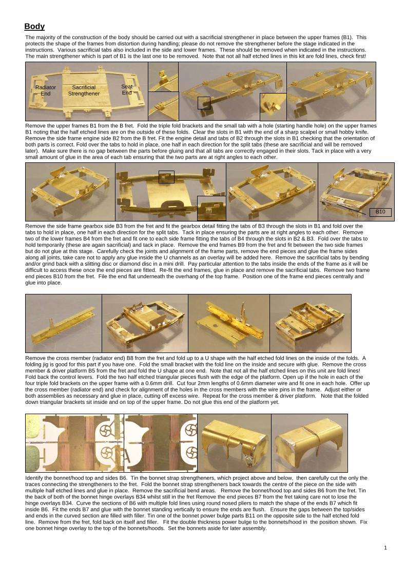
The majority of the construction of the body should be carried out with a sacrificial strengthener in place between the upper frames (B1). This protects the shape of the frames from distortion during handling; please do not remove the strengthener before the stage indicated in the instructions. Various sacrificial tabs also included in the side and lower frames. These should be removed when indicated in the instructions. The main strengthener which is part of B1 is the last one to be removed. Note that not all half etched lines in this kit are fold lines, check first!Sacrificial Strengthener
Seat End
Radiator End
Remove the upper frames B1 from the B fret. Fold the triple fold brackets and the small tab with a hole (starting handle hole) on the upper frames B1 noting that the half etched lines are on the outside of these folds. Clear the slots in B1 with the end of a sharp scalpel or small hobby knife. Remove the side frame engine side B2 from the B fret. Fit the engine detail and tabs of B2 through the slots in B1 checking that the orientation of both parts is correct. Fold over the tabs to hold in place, one half in each direction for the split tabs (these are sacrificial and will be removed later). Make sure there is no gap between the parts before gluing and that all tabs are correctly engaged in their slots. Tack in place with a very small amount of glue in the area of each tab ensuring that the two parts are at right angles to each other.
B10
Remove the side frame gearbox side B3 from the fret and fit the gearbox detail fitting the tabs of B3 through the slots in B1 and fold over the tabs to hold in place, one half in each direction for the split tabs. Tack in place ensuring the parts are at right angles to each other. Remove two of the lower frames B4 from the fret and fit one to each side frame fitting the tabs of B4 through the slots in B2 & B3. Fold over the tabs to hold temporarily (these are again sacrificial) and tack in place. Remove the end frames B9 from the fret and fit between the two side frames but do not glue at this stage. Carefully check the joints and alignment of the frame parts, remove the end pieces and glue the frame sides along all joints, take care not to apply any glue inside the U channels as an overlay will be added here. Remove the sacrificial tabs by bending and/or grind back with a slitting disc or diamond disc in a mini drill. Pay particular attention to the tabs inside the ends of the frame as it will be difficult to access these once the end pieces are fitted. Re-fit the end frames, glue in place and remove the sacrificial tabs. Remove two frame end pieces B10 from the fret. File the end flat underneath the overhang of the top frame. Position one of the frame end pieces centrally and glue into place.
Remove the cross member (radiator end) B8 from the fret and fold up to a U shape with the half etched fold lines on the inside of the folds. A folding jig is good for this part if you have one. Fold the small bracket with the fold line on the inside and secure with glue. Remove the cross member & driver platform B5 from the fret and fold the U shape at one end. Note that not all the half etched lines on this unit are fold lines! Fold back the control levers. Fold the two half etched triangular pieces flush with the edge of the platform. Open up if the hole in each of the four triple fold brackets on the upper frame with a 0.6mm drill. Cut four 2mm lengths of 0.6mm diameter wire and fit one in each hole. Offer up the cross member (radiator end) and check for alignment of the holes in the cross members with the wire pins in the frame. Adjust either or both assemblies as necessary and glue in place, cutting off excess wire. Repeat for the cross member & driver platform. Note that the folded down triangular brackets sit inside and on top of the upper frame. Do not glue this end of the platform yet.
Identify the bonnet/hood top and sides B6. Tin the bonnet strap strengtheners, which project above and below, then carefully cut the only the traces connecting the strengtheners to the fret. Fold the bonnet strap strengtheners back towards the centre of the piece on the side with multiple half etched lines and glue in place. Remove the sacrificial bend areas. Remove the bonnet/hood top and sides B6 from the fret. Tin the back of both of the bonnet hinge overlays B34 whilst still in the fret Remove the end pieces B7 from the fret taking care not to lose the hinge overlays B34. Curve the sections of B6 with multiple fold lines using round nosed pliers to match the shape of the ends B7 which fit inside B6. Fit the ends B7 and glue with the bonnet standing vertically to ensure the ends are flush. Ensure the gaps between the top/sides and ends in the curved section are filled with filler. Tin one of the bonnet power bulge parts B11 on the opposite side to the half etched fold line. Remove from the fret, fold back on itself and filler. Fit the double thickness power bulge to the bonnets/hood in the position shown. Fix one bonnet hinge overlay to the top of the bonnets/hoods. Set the bonnets aside for later assembly.
1
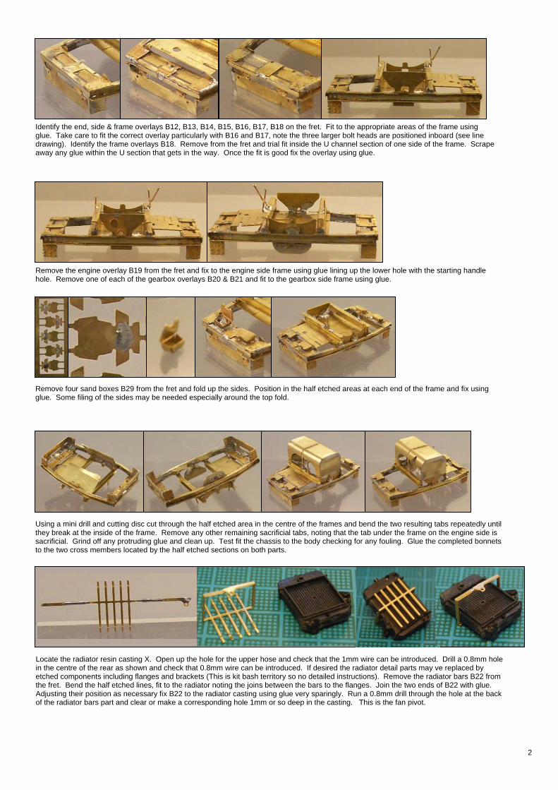
Remove the engine overlay B19 from the fret and fix to the engine side frame using glue lining up the lower hole with the starting handle hole. Remove one of each of the gearbox overlays B20 & B21 and fit to the gearbox side frame using glue.
Identify the end, side & frame overlays B12, B13, B14, B15, B16, B17, B18 on the fret. Fit to the appropriate areas of the frame using glue. Take care to fit the correct overlay particularly with B16 and B17, note the three larger bolt heads are positioned inboard (see line drawing). Identify the frame overlays B18. Remove from the fret and trial fit inside the U channel section of one side of the frame. Scrape away any glue within the U section that gets in the way. Once the fit is good fix the overlay using glue.
Remove four sand boxes B29 from the fret and fold up the sides. Position in the half etched areas at each end of the frame and fix using glue. Some filing of the sides may be needed especially around the top fold.
Using a mini drill and cutting disc cut through the half etched area in the centre of the frames and bend the two resulting tabs repeatedly until they break at the inside of the frame. Remove any other remaining sacrificial tabs, noting that the tab under the frame on the engine side is sacrificial. Grind off any protruding glue and clean up. Test fit the chassis to the body checking for any fouling. Glue the completed bonnets to the two cross members located by the half etched sections on both parts.
Locate the radiator resin casting X. Open up the hole for the upper hose and check that the 1mm wire can be introduced. Drill a 0.8mm hole in the centre of the rear as shown and check that 0.8mm wire can be introduced. If desired the radiator detail parts may ve replaced by etched components including flanges and brackets (This is kit bash territory so no detailed instructions). Remove the radiator bars B22 from the fret. Bend the half etched lines, fit to the radiator noting the joins between the bars to the flanges. Join the two ends of B22 with glue. Adjusting their position as necessary fix B22 to the radiator casting using glue very sparingly. Run a 0.8mm drill through the hole at the back of the radiator bars part and clear or make a corresponding hole 1mm or so deep in the casting. This is the fan pivot.
2

Cut a 30mm length of 1mm wire and form into the shape required for the upper radiator hose using the 1:1 plan view on the box liner. Trial fit between the underside of the bonnets and the hole at the top of the radiator and adjust and trim as needed. Bend the bonnets end of the wire so that the end is against the inside of the top of the bonnets close to the entry point checking that the entry point through the side is correct. Glue the radiator end of the hose wire and fix bonnets end in place with glue. THE FAN DRIVE ASSEMBLY SHOULD BE FITED AT THIS STAGE IF REQUIRED – SEE CHASSIS INSTRUCTIONS. Locate the exhaust resin casting W. If you decide to build the version with the etched exhaust support cut away the cast-in support on the exhaust, then remove the exhaust bracket B39 from the fret, fold into shape and fix to the frame. Trial fit the exhaust casting to the frame or bracket trimming the bonnet end to avoid fouling the fan drive gears. The exhaust should be level and parallel with the centre line of the loco. Fix in place with glue to the body cross member and top of the fan drive bracket.. Trial fit the chassis to the body and check for fouling. Grind away any problem areas of hidden etched parts with a cutting disc or burr in a mini drill.
Remove the seat base B29 from the fret and fold into a square. Test fit to the driver’s platform and adjust if necessary then glue the joining corner. Fit the seat base to the platform and secure with glue. Mount the M2 brass nut F over the hole in the driver’s platform within the seat. Solder in place taking care not to get any solder on the threads. Take the M2 brass cheesehead screw E and cut it so that there is 4mm of threads below the head. Check that it will screw into the nut from the underside of the body. Remove one of the seat tops B31 from the fret and fold into shape to fit the base. Remove one of the seat backs B30 from the fret including the rectangular strengthening piece. Fold the seat back double with the half etched fold line on the outside of the bend. Take great care this is a very delicate part, try again if you break the first one. Solder the back in place in its supports, remove the strengthening piece and fix the supports to the seat top using solder or metal epoxy.
Remove one of the brake columns B32 from the fret. Carefully fold the angles and curve the area around the hole to form the shape of the brake column. Fold the bracket at the base with the horizontal half etched fold line on the outside of the fold. Take great care this is a very delicate part, try again with the spare if you break the first one. Mount the brake column and bracket on the centre overlay at the driver’s end of the frame and fix in place with glue. Bear in mind the stress this part sees when fitting the driver and in general handling. Remove one of the brake wheels B33 from the fret. Cut an 15mm length of 0.8mm wire and feed through the hole in the centre of the brake wheel fixing with solder. Cut a 2mm length of 0.8mm wire and fit through the hole on the outer edge of the brake wheel. Fix in place with solder. Fit the longer length of wire through the hole in the top of the brake column and position the brake wheel trimming the wire if necessary. Fix in place.
3

Remove two of the spring buffers B35 from the frets and bend to shape. Open up the two small holes with a 0.6mm drill. Cut two 2mm lengths of 0.6mm wire and fit one to each of the holes in one end piece. Fit the bent buffer and fix in place.
Remove one of the hose straps B40 from the fret and form one end around a spare piece of 1mm wire or a 1mm drill shank. Form the shape of the strap and position over the upper radiator hose. Adjust position and shape, bending the lower end into a U between the chassis and body frames, and fix to the hose and inside of the body frame.
Tin the back of one of the clutch pedal tops B36 whilst still on the fret. Remove one of the clutch pedal tops B36 fit back to back on one of the clutch pedal backs B37 whilst still in the fret. Remove the combined clutch pedal from the fret and fit in the slot on the driver’s platform securing with glue. The pedal should project 6.5mm above the driver platform. Note: You may wish to fit the number plates after painting the remainder of the loco. Remove two of the number plates B38 from the fret and position on each side of the bonnet/hood. Fit the chassis to the body and secure with the M2.5 brass screw through the hole in the chassis tab into the nut in the seat base. Painting – the locos were originally painted in an olive drab colour, I suggest using Humbrol Slate Grey No 31 to represent a somewhat faded dirty and weathered state (thanks to Pete Wilson for this advice). The visible parts of the mechanism and much of the chassis etchings should also be painted, I suggest matt black for the areas which are not part of the model including the parts of the functional chassis frames which ‘should not be there’. This will help them sink into the background. The numbers on the number plate should be white, a white gel pen or white paint with extremely small brush can be used for this (magnifying glass recommended). The exhaust seems to be dark grey in most modern locos, I expect this or a rusty appearance is the closest to reality.
LR2832LR2832
4


![A9 re82f[1]](https://img.dokumen.tips/doc/110x75/55490d8fb4c90565458bb540/a9-re82f1.jpg)