Embed Size (px)
Citation preview

USER GUIDE AND TERMINAL BLOCK SPECIFICATIONS
NI PXIe-4302/4303 and TB-4302/4302C32 Ch, 24-bit, 5 kS/s or 51.2 kS/s Simultaneous Filtered Data Acquisition Module
This document explains how to install, configure, and set up the NI PXIe-4302 and NI PXIe-4303 (NI PXIe-4302/4303) simultaneous filtered modules with the TB-4302 and TB-4302C terminal blocks. Driver support for the NI PXIe-4302/4303 was first available in NI-DAQmx 15.1. For the list of devices supported by a specific release, refer to the NI-DAQmx Readme, available on the version-specific download page or installation media.
Note The keying of these terminal blocks prevents them from connecting to other modules that could be damaged by the voltage present on the terminal block. However, you should only use these terminal blocks with their supported modules.
ContentsElectromagnetic Compatibility Guidelines .............................................................................. 2What You Need to Get Started ................................................................................................. 3Installation ................................................................................................................................ 3
Install the Software ........................................................................................................... 3Unpack and Install the Module......................................................................................... 4Connect the Signals .......................................................................................................... 5Install the Terminal Block ................................................................................................ 8Confirm NI PXIe-4302/4303 Module Recognition.......................................................... 10Run Test Panels ................................................................................................................ 11Take an NI-DAQmx Measurement .................................................................................. 11
NI-DAQmx Channels and Tasks.............................................................................. 11Configure a Task Using the DAQ Assistant in MAX .............................................. 11
Use Your NI PXIe-4302/4303 Module in an Application................................................ 12Programming Examples ........................................................................................... 12
Terminal Block Removal.......................................................................................................... 13Module Removal ...................................................................................................................... 14Create a Simulated Device ....................................................................................................... 15
2 | ni.com | NI PXIe-4302/4303 and TB-4302/4302C
Cold-Junction Compensation (TB-4302 Only).........................................................................15Minimizing Thermal Gradients ................................................................................................15More Information......................................................................................................................16
Troubleshooting ................................................................................................................16Specifications (TB-4302/4302C) ..............................................................................................16Calibration Interval ...................................................................................................................17Electrical ...................................................................................................................................17
TB-4302 ............................................................................................................................17TB-4302C .........................................................................................................................17Mechanical........................................................................................................................17Physical .............................................................................................................................18Environmental Specifications ...........................................................................................18
Operating Environment.............................................................................................18Storage Environment ........................................................................................................19Shock and Vibration .........................................................................................................19Safety ................................................................................................................................19Safety Standards ...............................................................................................................19Electromagnetic Compatibility .........................................................................................20CE Compliance .................................................................................................................20Online Product Certification.............................................................................................20Environmental Management.............................................................................................21
World Wide Support and Services............................................................................................21
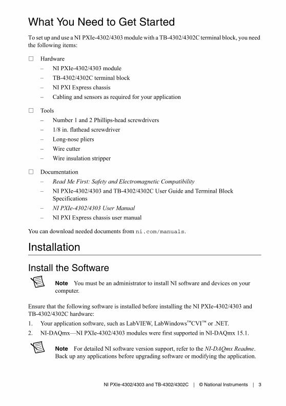
Electromagnetic Compatibility GuidelinesThis product was tested and complies with the regulatory requirements and limits for electromagnetic compatibility (EMC) stated in the product specifications. These requirements and limits provide reasonable protection against harmful interference when the product is operated in the intended operational electromagnetic environment.
This product is intended for use in industrial locations. However, harmful interference may occur in some installations, when the product is connected to a peripheral device or test object, or if the product is used in residential or commercial areas. To minimize interference with radio and television reception and prevent unacceptable performance degradation, install and use this product in strict accordance with the instructions in the product documentation.
Furthermore, any modifications to the product not expressly approved by National Instruments could void your authority to operate it under your local regulatory rules.
Caution To ensure the specified EMC performance, operate this product only with shielded, twisted pair cables and shielded accessories.
Caution To ensure the specified EMC performance, the length of all I/O cables must be no longer than 30 m (100 ft).
NI PXIe-4302/4303 and TB-4302/4302C | © National Instruments | 3
What You Need to Get StartedTo set up and use a NI PXIe-4302/4303 module with a TB-4302/4302C terminal block, you need the following items:
Hardware
– NI PXIe-4302/4303 module
– TB-4302/4302C terminal block
– NI PXI Express chassis
– Cabling and sensors as required for your application
Tools
– Number 1 and 2 Phillips-head screwdrivers
– 1/8 in. flathead screwdriver
– Long-nose pliers
– Wire cutter
– Wire insulation stripper
Documentation
– Read Me First: Safety and Electromagnetic Compatibility
– NI PXIe-4302/4303 and TB-4302/4302C User Guide and Terminal Block Specifications
– NI PXIe-4302/4303 User Manual
– NI PXI Express chassis user manual
You can download needed documents from ni.com/manuals.
Installation
Install the Software
Note You must be an administrator to install NI software and devices on your computer.
Ensure that the following software is installed before installing the NI PXIe-4302/4303 and TB-4302/4302C hardware:
1. Your application software, such as LabVIEW, LabWindows™CVI™ or .NET.
2. NI-DAQmx—NI PXIe-4302/4303 modules were first supported in NI-DAQmx 15.1.
Note For detailed NI software version support, refer to the NI-DAQmx Readme. Back up any applications before upgrading software or modifying the application.

4 | ni.com | NI PXIe-4302/4303 and TB-4302/4302C
Unpack and Install the ModuleRemove the packaging and inspect the module. Contact NI if the module is damaged. Do not install a damaged module.
Caution The module is static sensitive. Always properly ground yourself and the equipment when handling or connecting to the module.
Complete the following steps to install the NI PXIe-4302/4303 module while referring to Figures 1 and 2:
Note To maintain forced air cooling in the PXIe system, refer to the Maintain Forced-Air Cooling Note to Users.
1. Plug in your chassis before installing the NI PXIe-4302/4303. The power cord grounds the chassis and protects it from electrical damage while you install the module.
2. Make sure the chassis is powered off.
Caution To protect yourself, the chassis, and the NI PXIe-4302/4303 from electrical hazards, leave the chassis powered off until you finish installing the NI PXIe-4302/4303 module.
3. Touch a metal part on the chassis to discharge any accumulated static electricity.
4. Identify a supported PXI Express slot in the chassis. NI PXIe-4302/4303 modules can be placed only in PXI Express Peripheral slots, PXI Express Hybrid Peripheral slots, and PXI Express System Timing slots. Refer to the chassis documentation for details.
Figure 1. Symbols for PXI Express/ PXI Express Hybrid/ PXI Slots
5. Remove the filler panel, and touch any metal part of the chassis to discharge static electricity.
6. Place the module edges into the module guides at the top and bottom of the slot.
Caution When installing the module, make sure both edges are positioned inside the guides and that the module components do not come into contact with adjacent modules.
1 PXI Express System Controller Slot2 PXI Peripheral Slot
3 PXI Express Hybrid Peripheral Slot4 PXI Express System Timing Slot
NI PXIe-1062Q
1 2 3 4

NI PXIe-4302/4303 and TB-4302/4302C | © National Instruments | 5
7. Slide the module along the guides until it reaches the rear connector then seat the module by pushing the front panel until it is flush with the front panel of the chassis.
8. Secure the module to the chassis using the front-panel captive screws, shown in Figure 2. Tighten the screws to 0.31 N · m (2.7 lb · in.).
Figure 2. Installing NI PXIe-4302/4303 Modules
Connect the Signals
Caution For EMC compliance, operate this product with shielded cables and accessories.
To connect signals to the terminal block, refer to Figures 3 and, 4 or 5 while completing the following steps:
Note You can find the pinout names and locations in Measurement & Automation Explorer (MAX) at any time by right-clicking the device name under Devices and Interfaces and selecting Device Pinouts.
1. Loosen the captive top cover screws and remove the top cover.
2. Loosen the strain-relief screws and remove the strain-relief bar.
3. Prepare the shielded signal wire by stripping the insulation no more than 7 mm (0.28 in.).
1 Captive Screws
NI PXIe-1062Q
COOLING CLEARANCE AND FAN FILTER MAINTENANCE REQUIRED. SEE MANUAL.
1
6 | ni.com | NI PXIe-4302/4303 and TB-4302/4302C
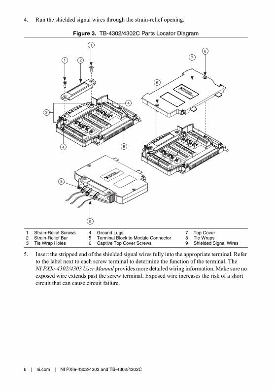
4. Run the shielded signal wires through the strain-relief opening.
Figure 3. TB-4302/4302C Parts Locator Diagram
5. Insert the stripped end of the shielded signal wires fully into the appropriate terminal. Refer to the label next to each screw terminal to determine the function of the terminal. The NI PXIe-4302/4303 User Manual provides more detailed wiring information. Make sure no exposed wire extends past the screw terminal. Exposed wire increases the risk of a short circuit that can cause circuit failure.
1 Strain-Relief Screws2 Strain-Relief Bar3 Tie Wrap Holes
4 Ground Lugs5 Terminal Block to Module Connector6 Captive Top Cover Screws
7 Top Cover8 Tie Wraps9 Shielded Signal Wires
3
1 2
1
4
6
7
6
54
8
9

NI PXIe-4302/4303 and TB-4302/4302C | © National Instruments | 7
Figure 4. TB-4302 Circuit Board Parts Locator Diagram
Figure 5. TB-4302C Circuit Board Parts Locator Diagram
Note Refer to the NI PXIe-4302/4303 User Manual for wiring diagrams showing how to connect sensors to the TB-4302/4302C.
6. Tighten the terminal screws to a torque of 0.2 to 0.25 N · m (1.77 to 2.21 lb · in.).
U7
AI3-
AI3+
AI2+
AI4+
AI4-
AI5-
AI7-
AI7+
AI6-
AI6+
AI5+
AI0+
AI0-
AI1-
AI2+
AI1+
AI9+
AI9-
AI10+
AI13+
AI13-
AI14+
AI15+
AI15-
AI14-
AI12+
AI11+
AI10-
AI8+
AI11-
AI8-
AI12-
AI7+
AI7-
AI18+
AI21+
AI21-
AI22+
AI23+
AI23-
AI22-
AI20+
AI19+
AI18-
AI6+
AI19-
AI6-
AI20-
AI5+
AI5-
AI16+
AI29+
AI29-
AI30+
AI31+
AI31-
AI30-
AI28+
AI17+
AI16-
AI4+
AI17-
AI4-
AI28-
FOR PATENTS: NI.COM/PATENTS
NI TB-4302S/N
158016B-01L
COPYRIGHT 2015UL94V-0
AIG
ND
AIG
ND
AIG
ND
AIG
ND
J21
J41
88
J5J3
J6J8
J9
J7
J10
J12
18
18
81
81
U6
U5
CR3
AIG
ND
AIG
ND
AIG
ND
AIG
ND
J15
J17
J11
J13
J18
J16
J14
81
81
U2
R2 U3
C1 U1
C3
C5C2R1
R5R6
R4
R7R8
R3
CR1U
4C6
CR2
C4
PFI0
DGND
FOR PATENTS: NI.COM/PATENTS
AI3
VSUP
AI2
VSUP
AI4
AI5
AI7
VSUP
AI6
VSUP
VSUP
VSUP
AI0
AI1
VSUP
VSUP
AI2
VSUP
AI1
VSUP
AI3
AI4
AI15
VSUP
AI8
VSUP
VSUP
VSUP
A9
AI0
VSUP
VSUP
AI19
VSUP
AI18
VSUP
AI20
AI21
AI23
VSUP
AI22
VSUP
VSUP
VSUP
AI16
AI17
VSUP
VSUP
AI28
VSUP
AI27
VSUP
AI29
AI30
AI31
VSUP
AI24
VSUP
VSUP
VSUP
A25
AI26
VSUP
VSUP
S/N
158141A-01L
NI TB-4302C
GND
PFI0
AISENSE
AISENSE
AISENSE
AISENSE
AISENSE
AISENSE
AISENSE
AISENSE
AISENSE
AISENSE
AISENSE
AISENSE
AISENSE
AISENSE
AISENSE
AISENSE
AISENSE
AIGND
AISENSE
VSUP
J2J4
J3J7
J5J9
J21
J19
J10J6
J15
J11
J17
U9
U11
U10
J12
J8
J13
J18
J16
J14
CR3
COPYRIGHT 2014

8 | ni.com | NI PXIe-4302/4303 and TB-4302/4302C
Caution Any wires connected to the ground must be sufficiently insulated from high voltage.
7. Use the ground lugs to attach a shield wire to the ground.
Note Refer to the NI PXIe-4302/4303 User Manual for details about shielding the signals.
8. Reinstall the strain-relief bar and tighten the strain-relief screws.
9. Use tie wraps to connect the shielded signal wires to the tie-wrap holes for additional strain relief when necessary.
10. Reinstall the top cover and tighten the captive top cover screws.
Note For information about sensors, go to ni.com/sensors.
Install the Terminal BlockRefer to Figure 6 to install the terminal block on the module while completing the following steps:
1. Move the TB-4302/4302C into position in front of the NI PXIe-4302/4303 and engage the alignment feature with the guide on the associated module.
Figure 6. Installing the TB-4302/4302C on the NI PXIe-4302/4303 Module
1 PXIe Controller2 PXIe Chassis
3 Mounting Screw4 TB-4302/4302C Terminal Block
5 NI PXIe-4302/4303 Module6 Alignment Feature
NI PXIe-1062Q
2
1
3
64
5
COOLING CLEARANCE AND FAN FILTER MAINTENANCE REQUIRED. SEE MANUAL.
COOLING CLEARANCE AND FAN FILTER MAINTENANCE REQUIRED. SEE MANUAL.
NI PXIe-4302/4303 and TB-4302/4302C | © National Instruments | 9
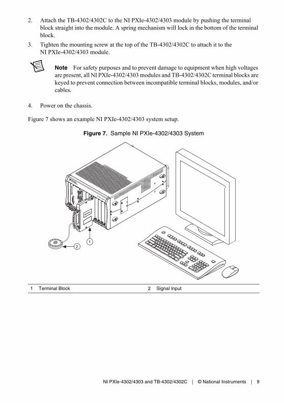
2. Attach the TB-4302/4302C to the NI PXIe-4302/4303 module by pushing the terminal block straight into the module. A spring mechanism will lock in the bottom of the terminal block.
3. Tighten the mounting screw at the top of the TB-4302/4302C to attach it to the NI PXIe-4302/4303 module.
Note For safety purposes and to prevent damage to equipment when high voltages are present, all NI PXIe-4302/4303 modules and TB-4302/4302C terminal blocks are keyed to prevent connection between incompatible terminal blocks, modules, and/or cables.
4. Power on the chassis.
Figure 7 shows an example NI PXIe-4302/4303 system setup.
Figure 7. Sample NI PXIe-4302/4303 System
1 Terminal Block 2 Signal Input
NI PXIe-1062Q
1
COOLING CLEARANCE AND FAN FILTER MAINTENANCE REQUIRED. SEE MANUAL.
COOLING CLEARANCE AND FAN FILTER MAINTENANCE REQUIRED. SEE MANUAL.
2
10 | ni.com | NI PXIe-4302/4303 and TB-4302/4302C
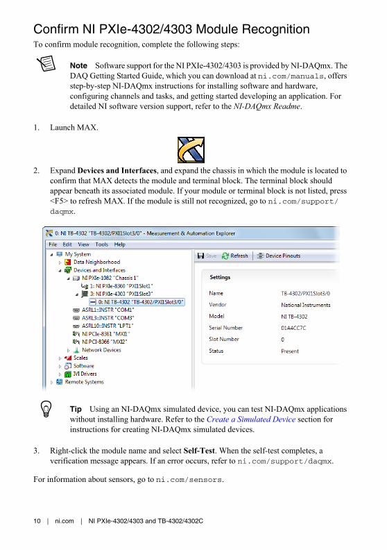
Confirm NI PXIe-4302/4303 Module RecognitionTo confirm module recognition, complete the following steps:
Note Software support for the NI PXIe-4302/4303 is provided by NI-DAQmx. The DAQ Getting Started Guide, which you can download at ni.com/manuals, offers step-by-step NI-DAQmx instructions for installing software and hardware, configuring channels and tasks, and getting started developing an application. For detailed NI software version support, refer to the NI-DAQmx Readme.
1. Launch MAX.
2. Expand Devices and Interfaces, and expand the chassis in which the module is located to confirm that MAX detects the module and terminal block. The terminal block should appear beneath its associated module. If your module or terminal block is not listed, press <F5> to refresh MAX. If the module is still not recognized, go to ni.com/support/daqmx.
Tip Using an NI-DAQmx simulated device, you can test NI-DAQmx applications without installing hardware. Refer to the Create a Simulated Device section for instructions for creating NI-DAQmx simulated devices.
3. Right-click the module name and select Self-Test. When the self-test completes, a verification message appears. If an error occurs, refer to ni.com/support/daqmx.
For information about sensors, go to ni.com/sensors.

NI PXIe-4302/4303 and TB-4302/4302C | © National Instruments | 11
Run Test Panels1. In MAX, expand Devices and Interfaces select the chassis in which the module is located.
2. Right-click the device, and select Test Panels.
3. Click Start to test device functions, or Help for operating instructions.
To troubleshoot errors, refer to the NI-DAQmx Help, or go to ni.com/support.
Take an NI-DAQmx Measurement
NI-DAQmx Channels and TasksRefer to the NI-DAQmx Help for complete information about channels and tasks.
Use the DAQ Assistant to configure virtual channels and tasks in MAX or in your application.
Configure a Task Using the DAQ Assistant in MAXComplete the following steps to create a task using the DAQ Assistant in MAX:
1. In MAX, right-click Data Neighborhood and select Create New to open the DAQ Assistant.
2. Select NI-DAQmx Task and click Next.
3. Select Acquire Signals.
4. Select the analog input, and the measurement type, such as voltage.
5. Select the physical channel(s) to use and click Next.
12 | ni.com | NI PXIe-4302/4303 and TB-4302/4302C
6. Name the task and click Finish.
7. Configure the individual channel settings. Each physical channel you assign to a task receives a virtual channel name. To modify the input range or other settings, select the channel. Click Details for physical channel information. Configure the timing and triggering for your task. Click Run.
Use Your NI PXIe-4302/4303 Module in an ApplicationFor NI software version compatibility, refer to the NI-DAQmx Readme, available from Start»All Programs»National Instruments»NI-DAQmx.
To get started with data acquisition in your application software, refer to the tutorials listed in Table 1.
Programming ExamplesNI-DAQmx includes example programs to help you get started developing an application. LabVIEW and CVI examples are located at Help»Find Examples in your application software. Text-based code examples are located at All Programs»National Instruments»NI-DAQmx»Text-Based Code Support. Modify example code and save it in an application, or use examples to develop a new application or add example code to an existing application.
For other examples, go to ni.com/info and enter the Info Code daqmxexp.
Table 1. DAQ Assistant Tutorial Locations
Application Tutorial Location
LabVIEW Go to ni.com and search for Taking an NI-DAQmx Measurement in LabVIEW.
LabWindows/CVI Go to Help»Contents. Next, go to Using LabWindows/CVI»Data Acquisition»Taking an NI-DAQmx Measurement in LabWindows/CVI.
Measurement Studio
Go to NI Measurement Studio Help»Getting Started with the Measurement Studio Class Libraries»Measurement Studio Walkthroughs»Walkthrough: Creating a Measurement Studio NI-DAQmx Application.
NI SignalExpress* Go to Help»Taking an NI-DAQmx Measurement in SignalExpress.
* NI SignalExpress, an easy-to-use configuration-based tool for data logging applications, is at Start»All Programs»National Instruments»NI SignalExpress.
NI PXIe-4302/4303 and TB-4302/4302C | © National Instruments | 13
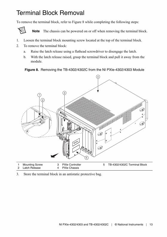
Terminal Block RemovalTo remove the terminal block, refer to Figure 8 while completing the following steps:
Note The chassis can be powered on or off when removing the terminal block.
1. Loosen the terminal block mounting screw located at the top of the terminal block.
2. To remove the terminal block:
a. Raise the latch release using a flathead screwdriver to disengage the latch.
b. With the latch release raised, grasp the terminal block and pull it away from the module.
Figure 8. Removing the TB-4302/4302C from the NI PXIe-4302/4303 Module
3. Store the terminal block in an antistatic protective bag.
1 Mounting Screw2 Latch Release
3 PXIe Controller4 PXIe Chassis
5 TB-4302/4302C Terminal Block
NI PXIe-1062Q
5
1
2 COOLING CLEARANCE AND FAN FILTER MAINTENANCE REQUIRED. SEE MANUAL.
COOLING CLEARANCE AND FAN FILTER MAINTENANCE REQUIRED. SEE MANUAL.
3
4
14 | ni.com | NI PXIe-4302/4303 and TB-4302/4302C
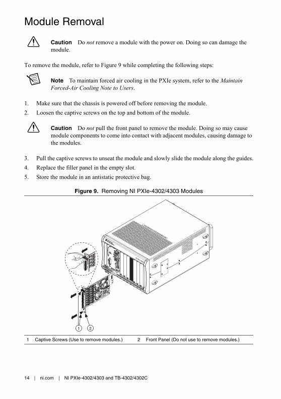
Module Removal
Caution Do not remove a module with the power on. Doing so can damage the module.
To remove the module, refer to Figure 9 while completing the following steps:
Note To maintain forced air cooling in the PXIe system, refer to the Maintain Forced-Air Cooling Note to Users.
1. Make sure that the chassis is powered off before removing the module.
2. Loosen the captive screws on the top and bottom of the module.
Caution Do not pull the front panel to remove the module. Doing so may cause module components to come into contact with adjacent modules, causing damage to the modules.
3. Pull the captive screws to unseat the module and slowly slide the module along the guides.
4. Replace the filler panel in the empty slot.
5. Store the module in an antistatic protective bag.
Figure 9. Removing NI PXIe-4302/4303 Modules
1 Captive Screws (Use to remove modules.) 2 Front Panel (Do not use to remove modules.)
NI PXIe-1062Q
COOLING CLEARANCE AND FAN FILTER MAINTENANCE REQUIRED. SEE MANUAL.
21

NI PXIe-4302/4303 and TB-4302/4302C | © National Instruments | 15
Create a Simulated DeviceTo run examples without the hardware installed, use an NI-DAQmx simulated device. To create a simulated device in MAX:
1. Launch MAX.
2. Right click Devices and Interfaces»Create New.
3. From the dialog, select Simulated NI-DAQmx Device or Modular Instrument.
4. Type 4302 or 4303 in the text box at the top of the window.
5. Select the device from the list provided.
6. Click OK.
Cold-Junction Compensation (TB-4302 Only)The TB-4302 contains a temperature sensor that is used to measure the temperature of the terminal block for cold-junction compensation, which is performed when computing the thermocouple temperature measurement.
Cold-junction compensation is the process of measuring the temperature of the screw terminal junction for the thermocouple and applying a representative compensating temperature to the temperature measured by the thermocouple channel. The accuracy of the cold-junction temperature measurement contributes to the accuracy of the overall thermocouple temperature measurement. The TB-4302 is designed to ensure high-accuracy cold-junction temperature measurements under a variety of conditions; however, care must be taken to ensure the best possible accuracy. Refer to the Minimizing Thermal Gradients section for guidelines to minimize thermal gradients that can impact the CJC accuracy. Refer to the TB-4302 section for the CJC accuracy specifications.
Minimizing Thermal GradientsThermal gradients can be caused by changes in the ambient air temperature near the terminal block, heat sources from other devices near the terminal block, or by the thermocouple wire if it conducts heat to or away from the terminal junctions. For optimal CJC accuracy performance, ensure that changes in ambient temperature and temperature gradients near the terminal block are kept to a minimum.
Follow these guidelines to minimize thermal gradients that can impact the CJC accuracy:
• Use the smallest gauge thermocouple wire suitable for the application. Smaller wire transfers less heat to or from the terminal junction.
• Run thermocouple wiring together near the terminal block to keep the wires at the same temperature.
• Avoid running thermocouple wires near hot or cold objects.
• If you connect any extension wires to thermocouple wires, use wires made of the same conductive material as the thermocouple wires.
• Minimize adjacent heat sources and air flow across the terminal block.

16 | ni.com | NI PXIe-4302/4303 and TB-4302/4302C
• Keep the ambient temperature as stable as possible.
• Keep the terminal block, module, and chassis in a stable and consistent orientation.
• Install the PXIe filler panels in any unused slots.
• When stacking the system, avoid stacking the chassis above a heat source as heat rises and can introduce error.
• Allow the thermal gradients to settle after a change in system power or in ambient temperature. A change in system power can occur when the system powers on. Refer to the warm-up time in the NI PXIe-4302/4303 Specifications for more information.
• If your PXIe chassis has fan filters, clean or replace them regularly to ensure proper system cooling. Refer to the PXI/PXI Express Chassis Fan Filter Kit document for more information.
Note Refer to the Maintain Forced-Air Cooling Note to Users for more information about maintaining optimal forced-air cooling for PXI/PXI Express devices.
More InformationAfter you install NI-DAQmx, the NI-DAQmx documentation is available from Start»All Programs»National Instruments»NI-DAQmx. Additional resources are online at ni.com/gettingstarted.
You can access online device documentation by right-clicking your module in MAX and selecting Help»Online Device Documentation. A browser window opens to ni.com/manuals with the results of a search for relevant documents. If you do not have Web access, documents for supported modules are included on the NI-DAQmx disc.
Troubleshooting• Go to ni.com/support/install or ni.com/kb.
• If you need to return your National Instruments hardware for repair or device calibration, go to ni.com/info and enter rdsenn to start the Return Merchandise Authorization (RMA) process.
Specifications (TB-4302/4302C)
Note NI PXIe-4302/4303 module specifications are located in the NI PXIe-4302/4303 Specifications document.
All performance specifications are typical unless otherwise noted. These specifications are valid within the full operating temperature range.
NI PXIe-4302/4303 and TB-4302/4302C | © National Instruments | 17
Calibration IntervalTB-4302............................................................ No calibration
TB-4302C ......................................................... 1 year interval (verification only)
Electrical
TB-4302Input range........................................................ Refer to NI PXIe-4302/4303 Specifications
CJC accuracy .................................................... 1.5 °C1, 2
TB-4302CInput range
Nominal .................................................... ±20 mA
Minimum .................................................. ±20.38 mA
Typical ...................................................... ±20.68 mA
Current shunt
Value ......................................................... 5 ΩAccuracy................................................... 0.5% max
Temperature stability ................................ 25 ppm/°C
Input impedancebetween AI to AISENSE .................................. 47 Ω
Max voltage of AISENSE ................................ ±8.4 V
Vsup pins
Current ...................................................... 2 A max
Voltage ...................................................... 30 V max
Overvoltage protectionbetween AI, AISENSE, and AIGND................ ±30 V for up to two AI pins
MechanicalScrew terminal wire gauge ............................... 1.5 mm2 (16 AWG), max
1 Combines CJC sensor accuracy and temperature difference between the CJC sensor and each screw terminal.
2 Represents performance for wire gauge of 24 AWG.
18 | ni.com | NI PXIe-4302/4303 and TB-4302/4302C
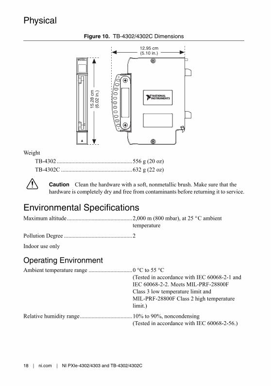
Physical
Figure 10. TB-4302/4302C Dimensions
Weight
TB-4302 ....................................................556 g (20 oz)
TB-4302C .................................................632 g (22 oz)
Caution Clean the hardware with a soft, nonmetallic brush. Make sure that the hardware is completely dry and free from contaminants before returning it to service.
Environmental SpecificationsMaximum altitude.............................................2,000 m (800 mbar), at 25 °C ambient
temperature
Pollution Degree ...............................................2
Indoor use only
Operating EnvironmentAmbient temperature range ..............................0 °C to 55 °C
(Tested in accordance with IEC 60068-2-1 and IEC 60068-2-2. Meets MIL-PRF-28800F Class 3 low temperature limit and MIL-PRF-28800F Class 2 high temperature limit.)
Relative humidity range....................................10% to 90%, noncondensing(Tested in accordance with IEC 60068-2-56.)
12.95 cm(5.10 in.)
15.2
8 cm
(6.0
2 in
.)

NI PXIe-4302/4303 and TB-4302/4302C | © National Instruments | 19
Storage EnvironmentAmbient temperature range .............................. -40 °C to 71 °C
(Tested in accordance with IEC 60068-2-1 and IEC 60068-2-2. Meets MIL-PRF-28800F Class 3 limits.)
Relative humidity range.................................... 5% to 95%, noncondensing (Tested in accordance with IEC 60068-2-56.)
Shock and VibrationOperating shock................................................ 30 g peak, half-sine, 11 ms pulse
(Tested in accordance with IEC 60068-2-27. Meets MIL-PRF-28800F Class 2 limits.)
Random vibration
Operating .................................................. 5 Hz to 500 Hz, 0.3 grms
Non-operating........................................... 5 Hz to 500 Hz, 2.4 grms (Tested in accordance with IEC 60068-2-64. Non-operating test profile exceeds the requirements of MIL-PRF-28800F, Class 3.)
SafetyMeasurement Category..................................... I1
Caution Do not connect the TB-4302/4302C to signals or use for measurements within Measurement Categories II, III or IV.
Caution The protection provided by the TB-4302/4302C can be impaired if it is used in a manner not described in this document.
Safety StandardsThis product meets the requirements of the following standards of safety for electrical equipment for measurement, control, and laboratory use:
• IEC 61010-1, EN 61010-1
• UL 61010-1, CSA 61010-1
Note For UL and other safety certifications, refer to the product label or the Online Product Certification section.
1 Measurement Categories CAT I and CAT O are equivalent. These test and measurement circuits are not intended for direct connection to the MAINS building installations of Measurement Categories CAT II, CAT III, or CAT IV.

20 | ni.com | NI PXIe-4302/4303 and TB-4302/4302C
Electromagnetic CompatibilityThis product meets the requirements of the following EMC standards for electrical equipment for measurement, control, and laboratory use:
• EN 61326-1 (IEC 61326-1): Class A emissions; Basic immunity
• EN 55011 (CISPR 11): Group 1, Class A emissions
• EN 55022 (CISPR 22): Class A emissions
• EN 55024 (CISPR 24): Immunity
• AS/NZS CISPR 11: Group 1, Class A emissions
• AS/NZS CISPR 22: Class A emissions
• FCC 47 CFR Part 15B: Class A emissions
• ICES-001: Class A emissions
Note In the United States (per FCC 47 CFR), Class A equipment is intended for use in commercial, light-industrial, and heavy-industrial locations. In Europe, Canada, Australia and New Zealand (per CISPR 11) Class A equipment is intended for use only in heavy-industrial locations.
Note Group 1 equipment (per CISPR 11) is any industrial, scientific, or medical equipment that does not intentionally generate radio frequency energy for the treatment of material or inspection/analysis purposes.
Note For the standards applied to assess the EMC of this product, refer to the Online Product Certification section.
CE ComplianceThis product meets the essential requirements of applicable European Directives as follows:
• 2014/35/EU; Low-Voltage Directive (safety)
• 2014/30/EU; Electromagnetic Compatibility Directive (EMC)
Online Product CertificationRefer to the product Declaration of Conformity (DoC) for additional regulatory compliance information. To obtain product certifications and the DoC for this product, visit ni.com/certification, search by model number or product line, and click the appropriate link in the Certification column.

NI PXIe-4302/4303 and TB-4302/4302C | © National Instruments | 21
Environmental ManagementNI is committed to designing and manufacturing products in an environmentally responsible manner. NI recognizes that eliminating certain hazardous substances from our products is beneficial to the environment and to NI customers.
For additional environmental information, refer to the Minimize our Environmental Impact Web page at ni.com/environment. This page contains the environmental regulations and directives with which NI complies, as well as other environmental information not included in this document.
Waste Electrical and Electronic Equipment (WEEE)EU Customers At the end of the product life cycle, all products must be sent to a WEEE recycling center. For more information about WEEE recycling centers, National Instruments WEEE initiatives, and compliance with WEEE Directive 2002/96/EC on Waste and Electronic Equipment, visit ni.com/environment/weee.
World Wide Support and ServicesThe National Instruments website is your complete resource for technical support. At ni.com/support you have access to everything from troubleshooting and application development self-help resources to email and phone assistance from NI Application Engineers.
Visit ni.com/services for NI Factory Installation Services, repairs, extended warranty, and other services.
Visit ni.com/register to register your National Instruments product. Product registration facilitates technical support and ensures that you receive important information updates from NI.
National Instruments corporate headquarters is located at 11500 North Mopac Expressway, Austin, Texas, 78759-3504. National Instruments also has offices located around the world. For telephone support in the United States, create your service request at ni.com/support or dial 1 866 ASK MYNI (275 6964). For telephone support outside the United States, visit the Worldwide Offices section of ni.com/niglobal to access the branch office websites, which provide up-to-date contact information, support phone numbers, email addresses, and current events.
RoHSNational Instruments
(RoHS) National Instruments RoHS ni.com/environment/rohs_china (For information about China RoHS compliance, go to ni.com/environment/rohs_china.)

© 2015 National Instruments. All rights reserved.
377008A-01 Jul15
Refer to the NI Trademarks and Logo Guidelines at ni.com/trademarks for more information on National Instruments trademarks. Other product and company names mentioned herein are trademarks or trade names of their respective companies. For patents covering National Instruments products/technology, refer to the appropriate location: Help»Patents in your software, the patents.txt file on your media, or the National Instruments Patents Notice at ni.com/patents. You can find information about end-user license agreements (EULAs) and third-party legal notices in the readme file for your NI product. Refer to the Export Compliance Information at ni.com/legal/export-compliance for the National Instruments global trade compliance policy and how to obtain relevant HTS codes, ECCNs, and other import/export data. NI MAKES NO EXPRESS OR IMPLIED WARRANTIES AS TO THE ACCURACY OF THE INFORMATION CONTAINED HEREIN AND SHALL NOT BE LIABLE FOR ANY ERRORS. U.S. Government Customers: The data contained in this manual was developed at private expense and is subject to the applicable limited rights and restricted data rights as set forth in FAR 52.227-14, DFAR 252.227-7014, and DFAR 252.227-7015.