Embed Size (px)
Citation preview
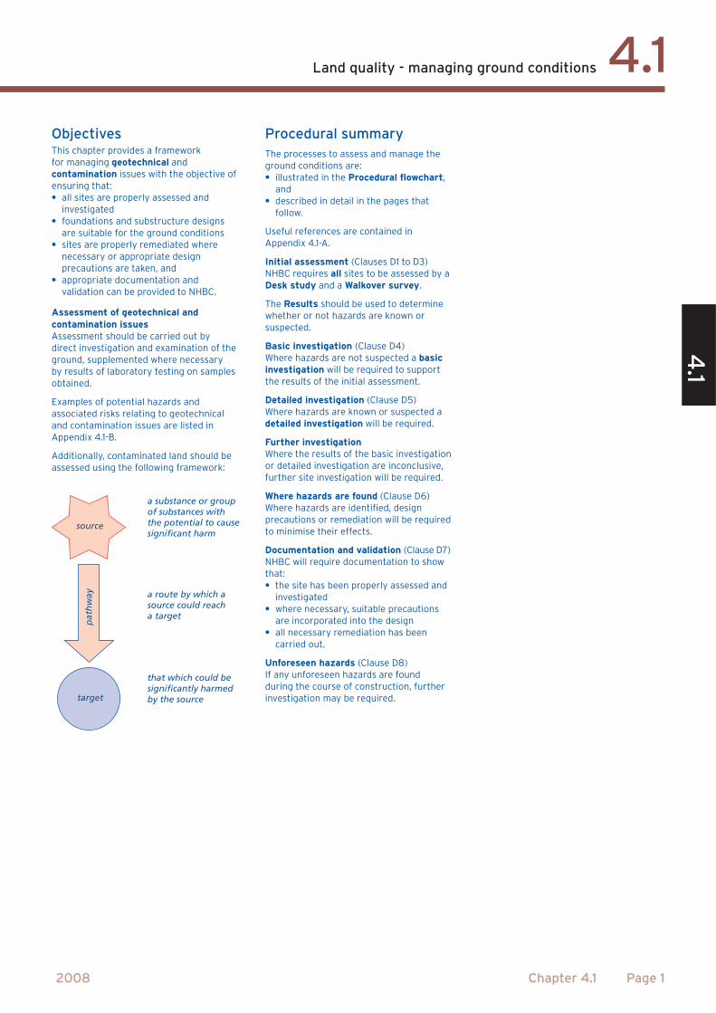
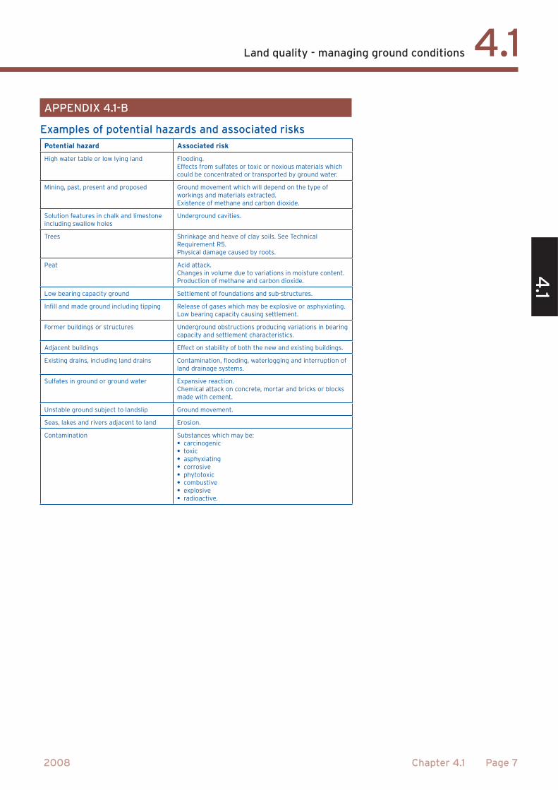
a substance or groupof substances withthe potential to causesignificant harm
a route by which asource could reacha target
that which could besignificantly harmedby the source
source
pat
hw
ay
target
NO
NO
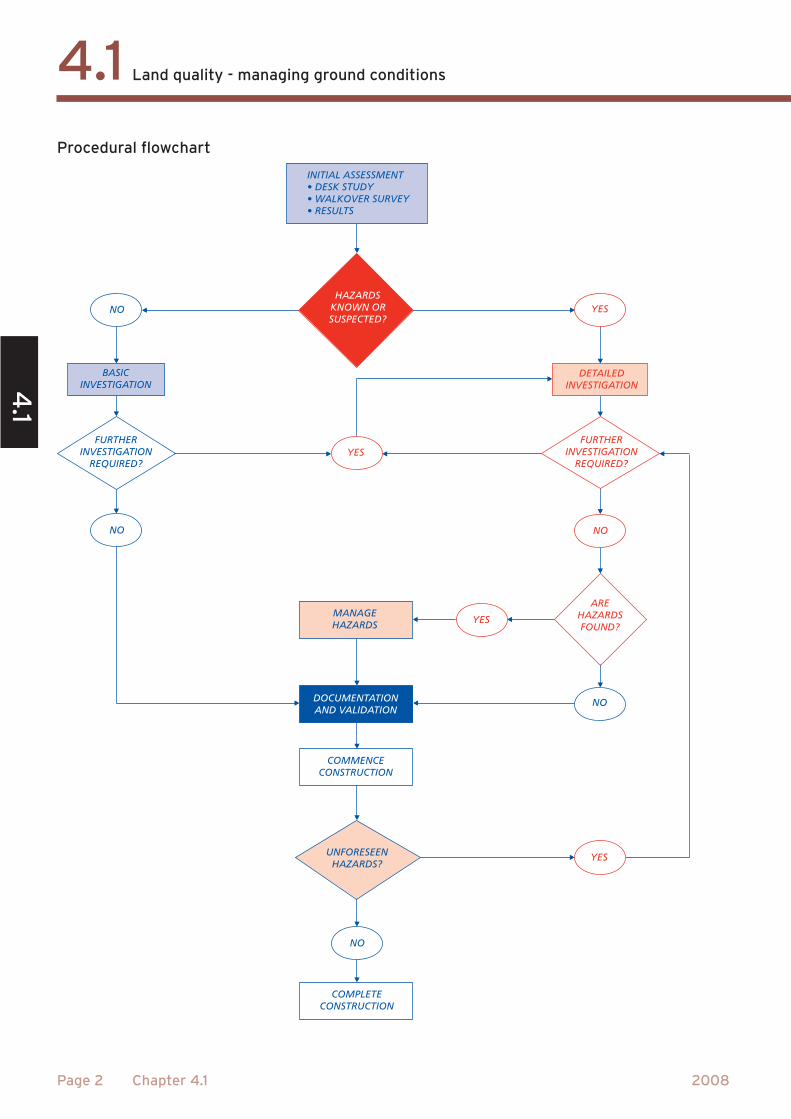
HAZARDSKNOWN ORSUSPECTED?
YES
YES
NO
YES
NO
NO
YES
BASICINVESTIGATION
DETAILEDINVESTIGATION
INITIAL ASSESSMENTY
ALKOVER SURVEYTS
FURTHERINVESTIGATION
REQUIRED?
FURTHERINVESTIGATION
REQUIRED?
AREHAZARDSFOUND?
DOCUMENTATIONAND VALIDATION
COMMENCECONSTRUCTION
UNFORESEENHAZARDS?
COMPLETECONSTRUCTION
MANAGEHAZARDS
‘A few years backthere was a tip in
the area.’
WATER LANE
°
μ
μ
μ
μ
μ
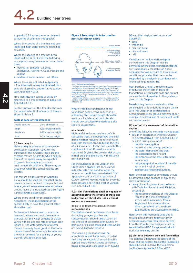
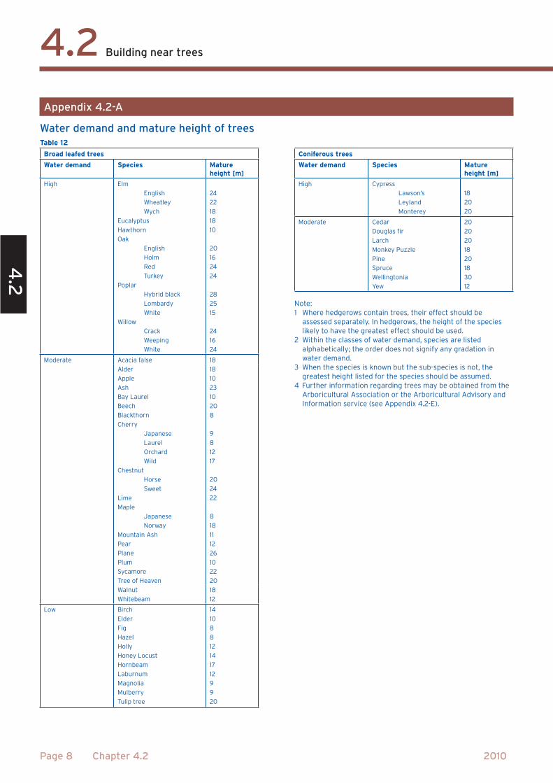
mature height
50% mature height
In this range useH = mature height
as listed inAppendix 4.2-B
In this range useH = actual height
Figure 1 should be used when:
T equal to orgreater than B
B
acceptablefoundationdepth
depthgreaterthan3/4 X
depth Xdeterminedassumingsoil isshrinkable
no
n s
hri
nka
ble
so
ilsh
rin
kab
le s
oil
°
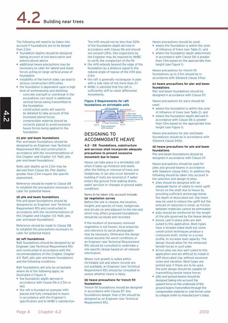
0.5 m 0.5 m level formation
raft foundation
angle of repose of
infill material
ground level
1.25m max.depth (measuredin accordance withSitework clause S3)
fully compactedinfill material
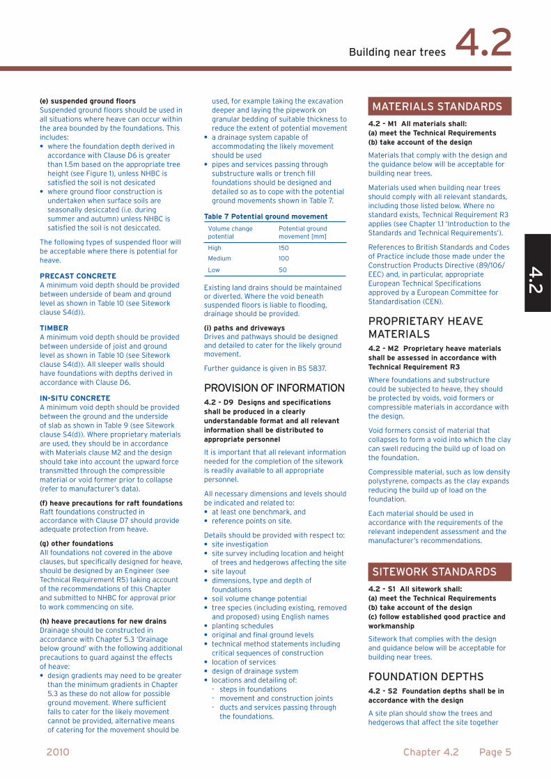
Foundation details
Tree details
Site Details
Unaltered
High
0.00
0.00
Volume change potential:
Ground level:
Ground level altered by(m):
Climate zone depthreduction (m):
NextHelp Climate zones
Site Details
Unaltered
High
0.00
0.00
Volume change potential:
Ground level:
Ground level altered by(m):
Climate zone depthreduction (m):
NextHelp Climate zones
NHBC Standards
Chapter 4.2
Building near trees
Electronic foundationdepth calculator
Help Continue
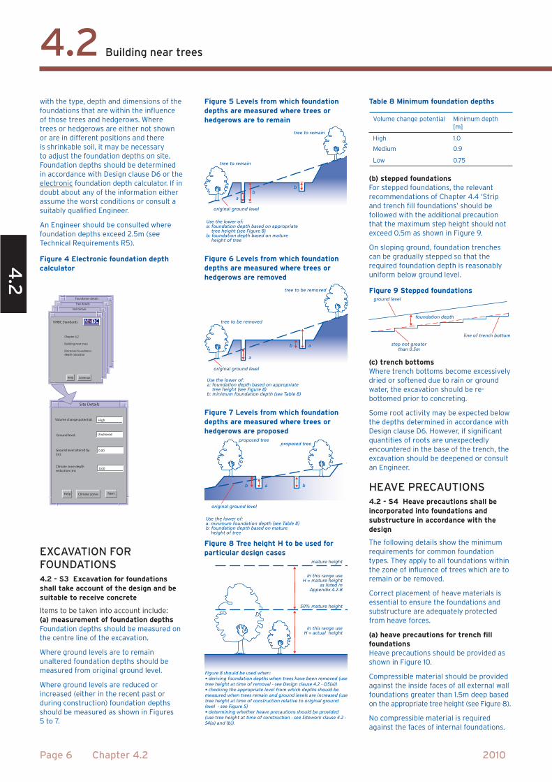
tree to remain
tree to remain
original ground level
Use the lower of: a: foundation depth based on appropriate tree height (see Figure 8)b: foundation depth based on mature height of tree
ab
b
tree to be removed
tree to be removed
original ground level
Use the lower of: a: foundation depth based on appropriate tree height (see Figure 8)b: minimum foundation depth (see Table 8)
a
ab
proposed treeproposed tree
original ground level
bb a
Use the lower of:a: minimum foundation depth (see Table 8)b: foundation depth based on mature height of tree
mature height
50% mature height
In this range useH = mature height
as listed inAppendix 4.2-B
In this range useH = actual height
Figure 8 should be used when:
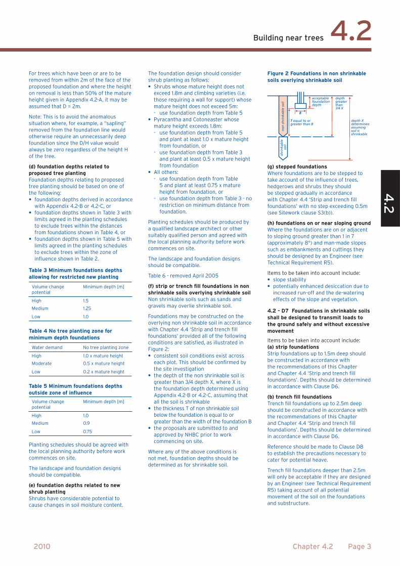
line of trench bottom
step not greater than 0.5m
foundation depth
ground level
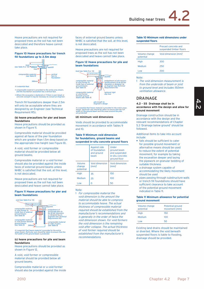
backfill
500mm
450mmmax
verticalface to foundation
compressible material (see Table 9)
Void(see Table 9 or 10)
It is essential that:
and the foundation excavation has a vertical face.
concrete overspill it may be necessary to consult an Engineer.
backfill
embedment ofanchorage bars tobe 40 bar diametersor designed by anEngineer (see TechnicalRequirement R5)
compressible materialto sides of piers(see Table 9)
compressible materialor void former toinside face of externalground beams(see Table 9)
compressible materialor void former beneathground beams(see Table 9)
void (see Table 9 or 10)
500mm
It is essential that heave material is provided to the entireareas shown. Particular care should be taken to ensure that the full width of the ground beam is protected.
backfill
embedment of pile tensionreinforcement to be 40 bardiameters or designed byan Engineer (see TechnicalRequirement R5)
optional rigidslip liner
pile length toEngineer's design
compressible materialor void former toinside face of externalground beams(see Table 9)
compressible materialor void formerbeneath groundbeams (see Table 9)
Void (see Table 9 or 10)
It is essential that heave material is provided to the entire areas shown. Particular care should be taken to ensure that the full width of the ground beam and the areas around the piles are protected.
0 0.2 0.4 0.6 0.8 1.0 1.2
0
0.5
1.0
1.5
2.0
2.5
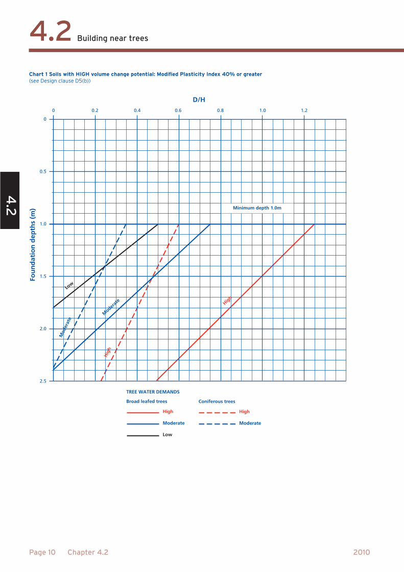
Minimum depth 1.0m
Fou
nd
atio
n d
epth
s (m
)
D/H
Low
Moder
ate
Mod
erat
e
Hig
h
High
TREE WATER DEMANDS
Broad leafed trees Coniferous trees
High
Moderate
Low
High
Moderate
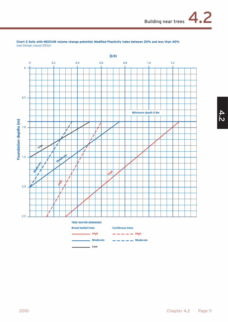
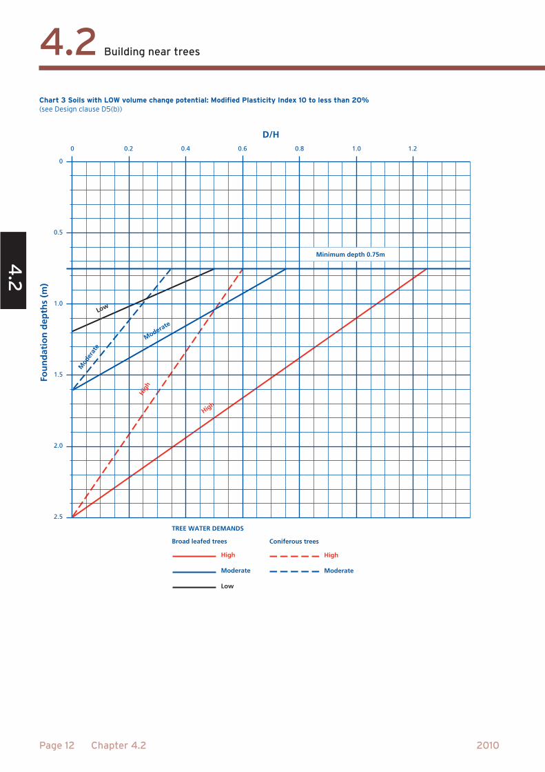
D/H
Low
Moderate
Mod
erat
e
Hig
h
High
Fou
nd
atio
n d
epth
s (m
)
0.2 0.4 0.6 0.8 1.0 1.2
0
0.5
1.0
1.5
2.0
2.5
TREE WATER DEMANDS
Broad leafed trees Coniferous trees
High
Moderate
Low
High
Moderate
Minimum depth 0.9m
0
D/H
Low
Moderate
Mod
erat
e
Hig
h
High
Fou
nd
atio
n d
epth
s (m
)
Minimum depth 0.75m
0.2 0.4 0.6 0.8 1.0 1.2
0
0.5
1.0
1.5
2.0
2.5
0
TREE WATER DEMANDS
Broad leafed trees Coniferous trees
High
Moderate
Low
High
Moderate
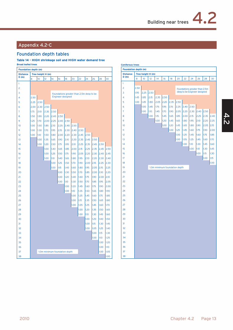
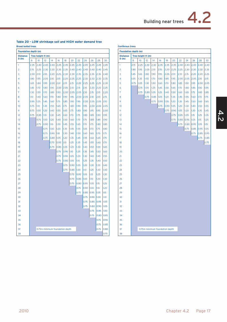
36 0.9m minimum foundation depth
37
38

Thurso
Wick
Dingwall
Inverness
Fort William
Oban
Pitlochry
Perth
Glasgow
Ayr
DumfriesLondonderry
Belfast
Douglas
Blackpool
Holyhead
Conwy
Shrewsbury
Aberystwyth
Lancaster
Edinburgh
Dunbar
Berwick Upon Tweed
Newcastle Tynemouth
MiddlesbroughDarlington
Carlisle
Montrose
Peterhead
Cardigan
Pembroke
Ilfracombe
ExeterTaunton
Bristol
Salisbury
Poole
WeymouthPlymouth
Penzance
Brecon
WorcesterBirmingham
Stafford
Stoke on Trent
ChesterLiverpool
Manchester
Lincoln
Derby
LeicesterKings Lynn
Norwich
Skegness
Grimsby
Hull
York
Scarborough
Leeds
Yarmouth
Cambridge
Banbury
Cheltenham
Oxford
SwindonReading
Winchester
Southampton
Hastings
Dover
MargateLondon
Chelmsford
Colchester
Portsmouth
Brighton
Newport
Cardiff
St. Austell
Swansea
Enniskillen
Barrow-in-Furness
Aberdeen
Lowestoft
Ipswich
Barnstaple
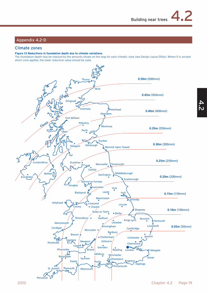
0.50m (500mm)
0.45m (450mm)
0.40m (400mm)
0.35m (350mm)
0.30m (300mm)
0.25m (250mm)
0.20m (200mm)
0.15m (150mm)
0.10m (100mm)
0.05m (50mm)
μ
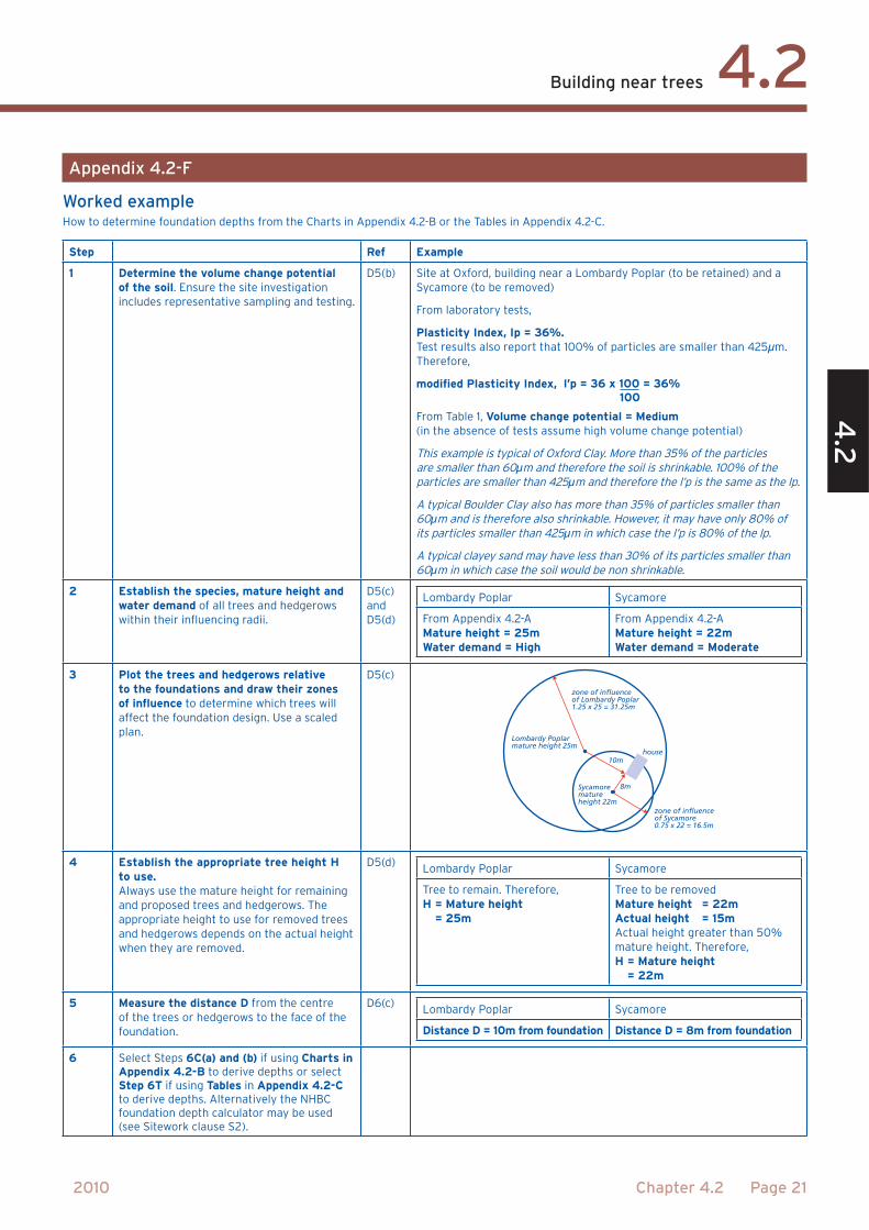
100l’p = 36 x 100 = 36%
μμ
μμ
μ
Lombardy Poplarmature height 25m
zone of influenceof Lombardy Poplar1.25 x 25 = 31.25m
zone of influenceof Sycamore 0.75 x 22 = 16.5m
Sycamorematureheight 22m
8m
10mhouse
H 25D = 10 = 0.4
H 22D = 8 = 0.36
HD= 0.4,
HD= 0.36,
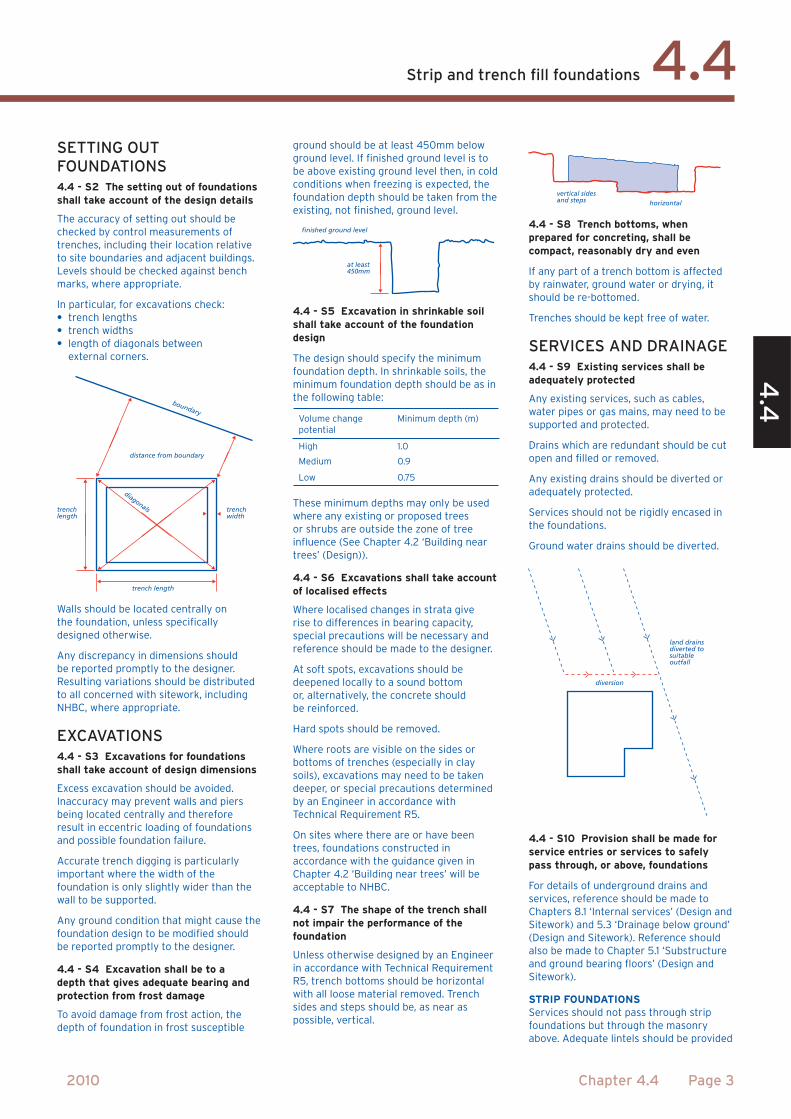
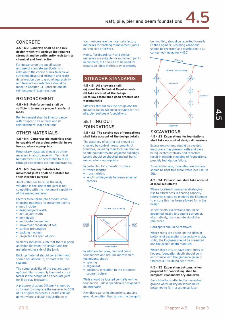
trench length
trenchlength
distance from boundary
trenchwidth
boundary
diagonals
finished ground level
at least 450mm
vertical sidesand steps horizontal
land drainsdiverted tosuitableoutfall
diversion
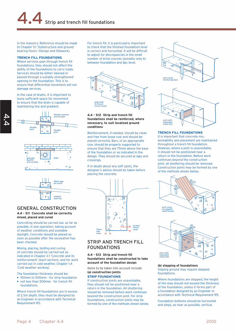
50mm gap all round
maskedopening
flexiblejoint
granularbackfillaround pipe
lintel
flexiblejoint
flexible materialaround pipe
pegs helpto ensurecorrect levels
at least 75mmcover75mm
sidecover
joint using reinforcing bars
joint withexpandedmetal lath
joint using corrugatedmetal former
joint with expandedmetal lath
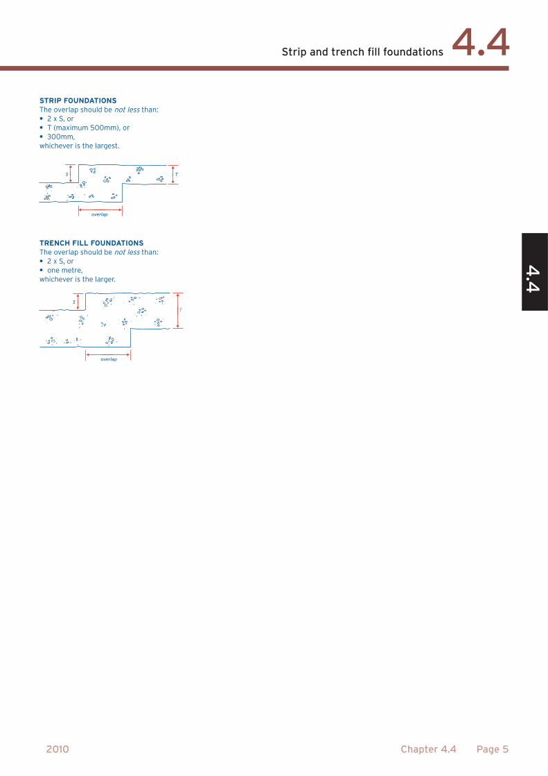
overlap
TS
S
overlap
T
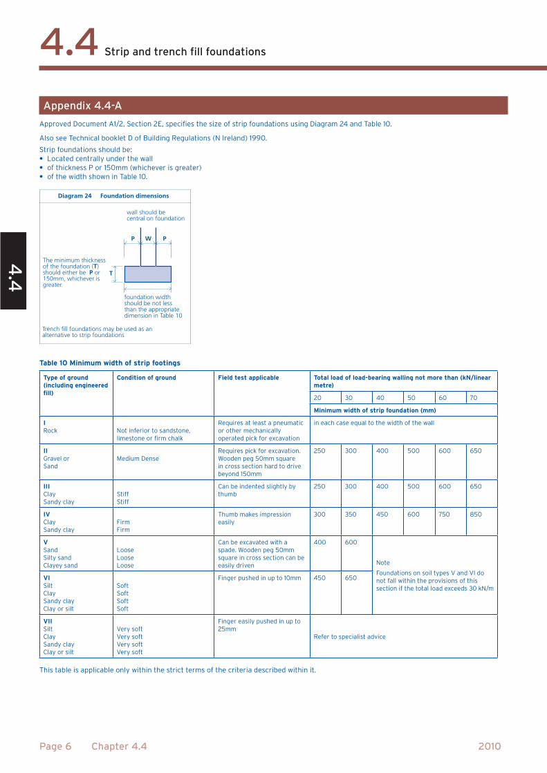
The minimum thicknessof the foundation (T)should either be P or150mm, whichever is greater.
foundation widthshould be not lessthan the appropriatedimension in Table 10
wall should becentral on foundation
Diagram 24 Foundation dimensions
P PW
T
Trench fill foundations may be used as analternative to strip foundations
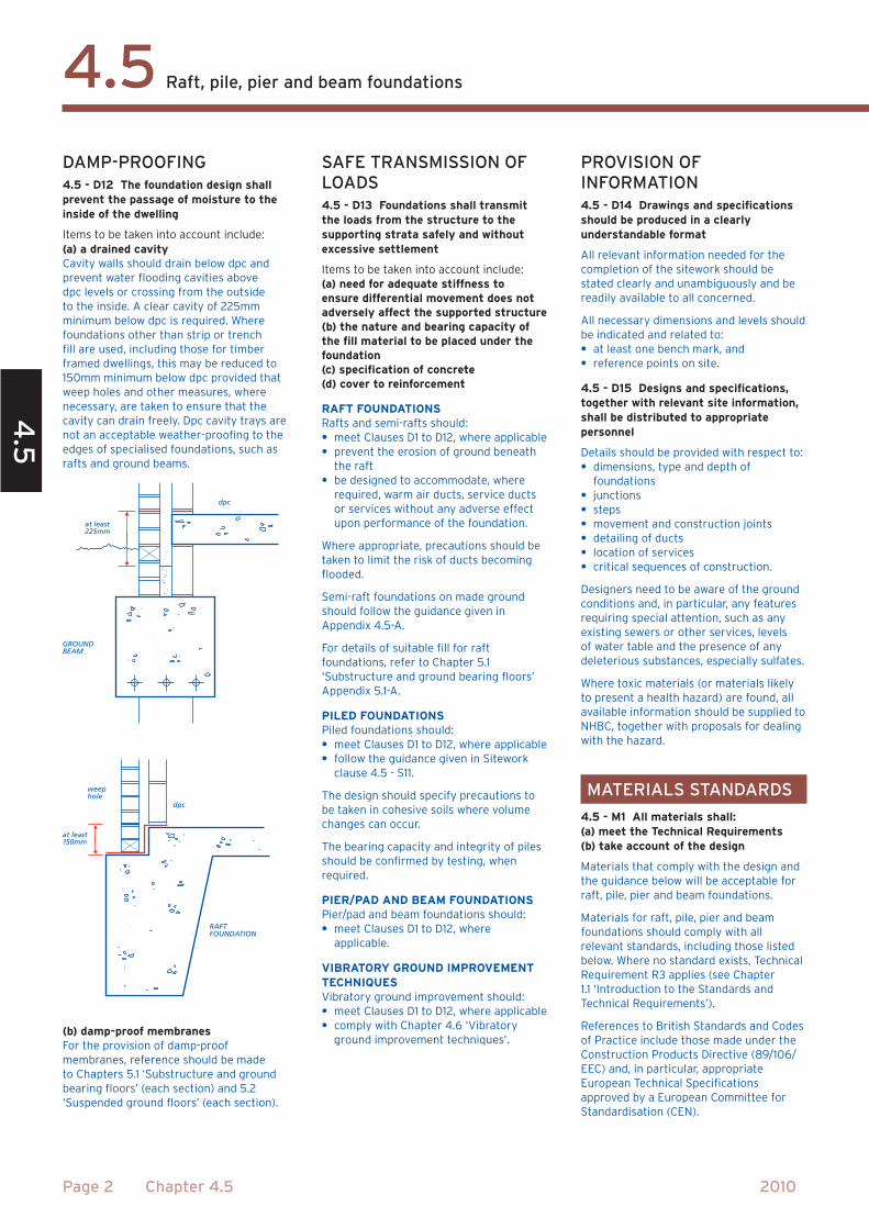
dpc
at least225mm
GROUNDBEAM
dpc
at least 150mm
weephole
RAFTFOUNDATION
trench length
trenchlength
distance from boundary
trenchwidth
boundary
diagonals
boundary
distance from boundary
diagonals
alignment
alignment
°
100
90
80
70
60
50
40
30
20
10
0
CLAYFine Medium
SILT
Coarse Fine Medium
SAND
Coarse Fine Medium
GRAVELCOBBLES
Coarse
6 20 60 200 600 2 6 20 60 200 mm2
Micr
on
PERC
ENTA
GE
PASS
ING
63 150
212
300
425
600
mm
1.18
2 3.35
5 6.3
10 14 20 28 37.5
50 63 75
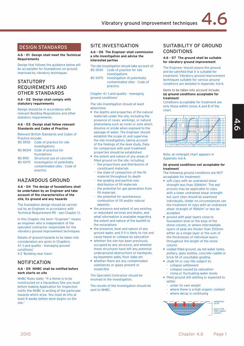
Zone Adeepcompaction
Zone Bstonecolumns
settlementof fill
layers withhigh organiccontent
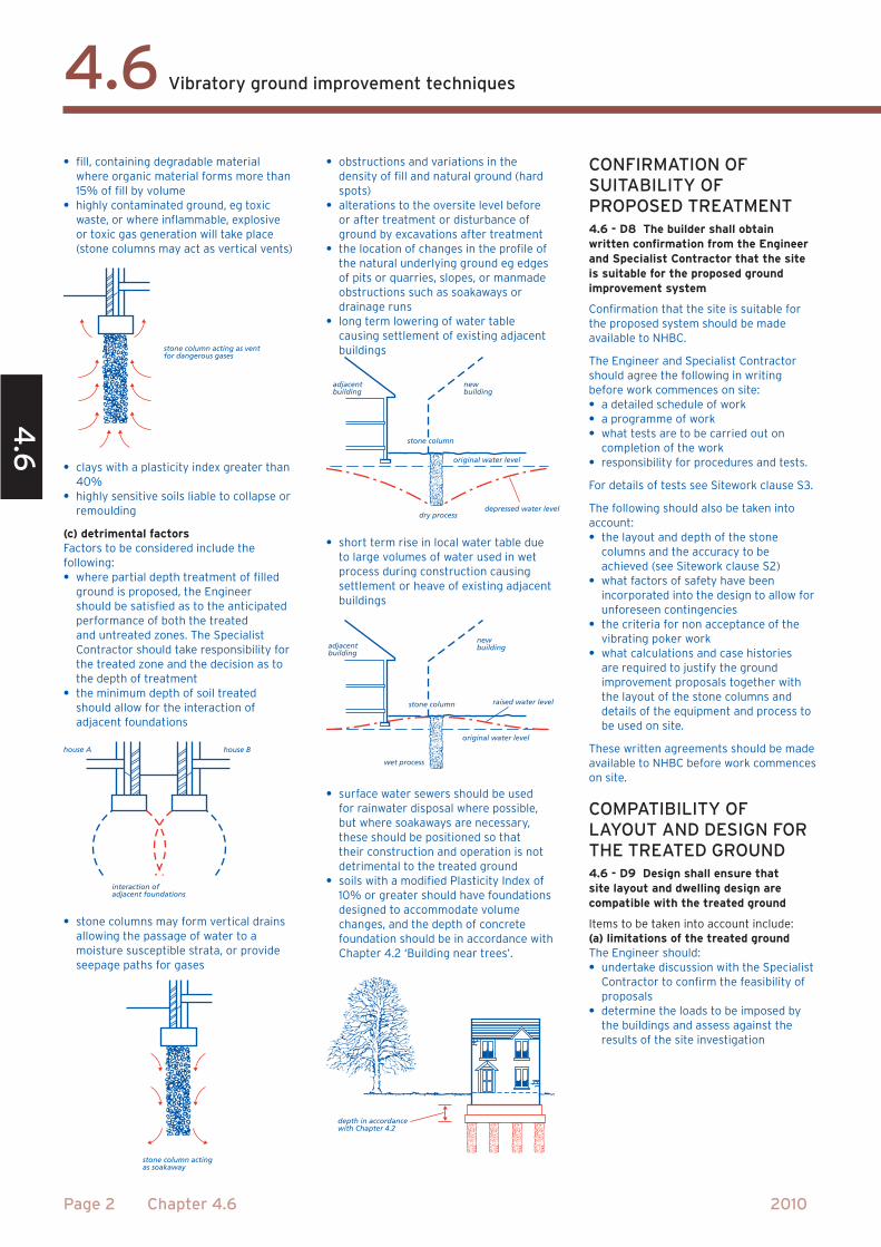
stone column acting as vent for dangerous gases
interaction ofadjacent foundations
house A house B
stone column acting as soakaway
adjacentbuilding
newbuilding
stone column
original water level
depressed water leveldry process
adjacentbuilding
newbuilding
stone column raised water level
original water level
wet process
depth in accordance with Chapter 4.2
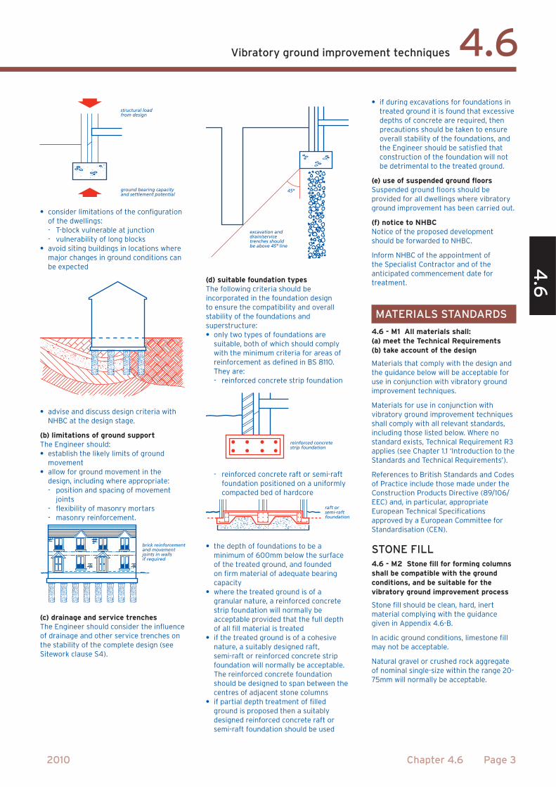
structural load from design
ground bearing capacity and settlement potential
brick reinforcementand movementjoints in walls if required
excavation and drain/servicetrenches shouldbe above 45º line
45º
reinforced concretestrip foundation
raft orsemi-raftfoundation
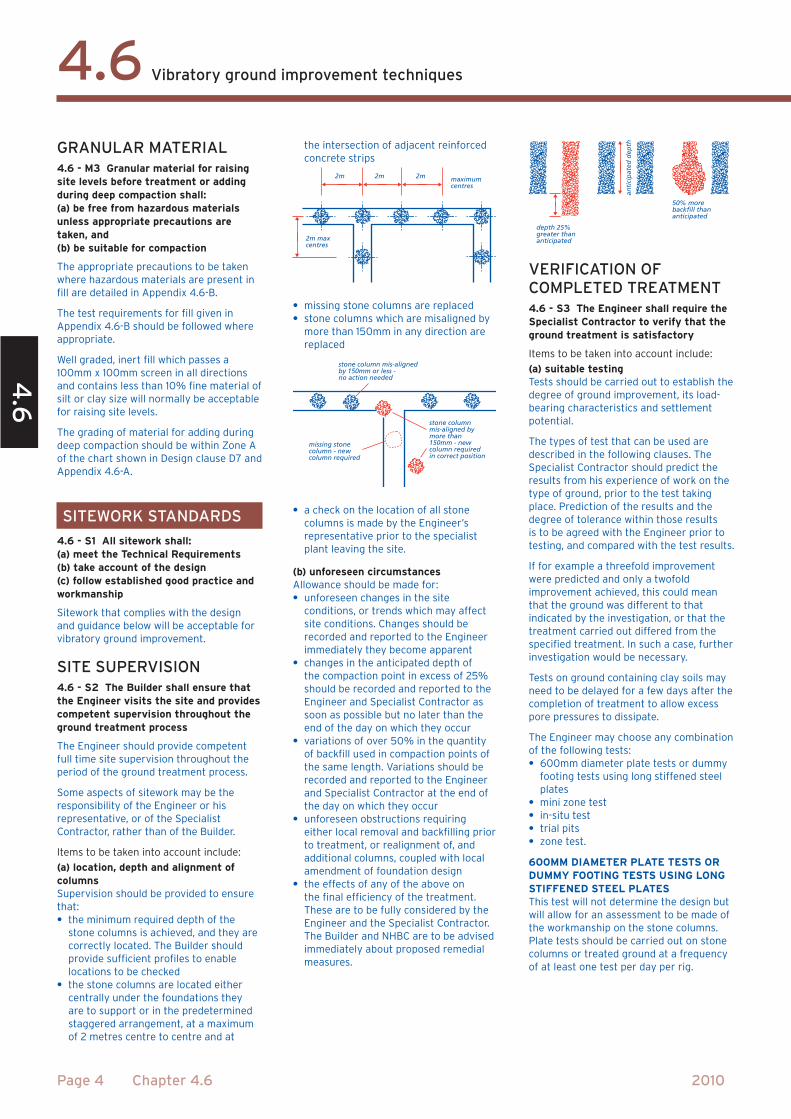
maximumcentres
2m max centres
2m 2m 2m
missing stonecolumn - new column required
stone column mis-aligned by more than 150mm - new column requiredin correct position
stone column mis-aligned by 150mm or less - no action needed
depth 25%greater thananticipated
50% more backfill than anticipated
anti
cip
ated
dep
th
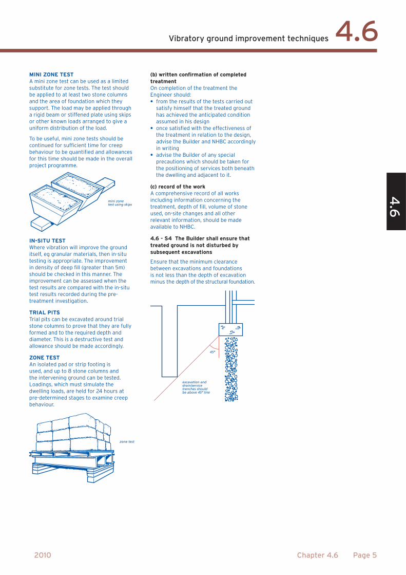
mini zonetest using skips
zone test
excavation and drain/servicetrenches shouldbe above 45º line
45º
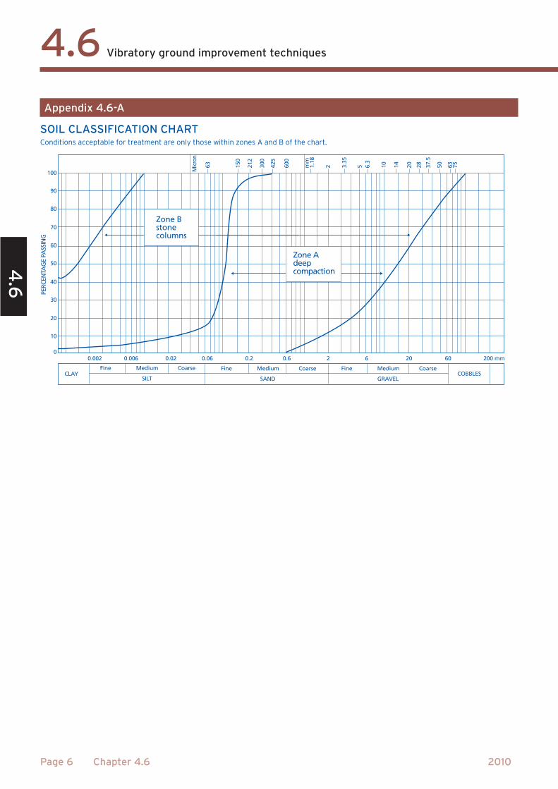
100
90
80
70
60
50
40
30
20
10
0
CLAYFine Medium
SILT
Coarse Fine Medium
SAND
Coarse Fine Medium
GRAVELCOBBLES
Coarse
0.006 0.02 0.06 0.2 0.6 2 6 20 60 200 mm0.002
Micr
on
PERC
ENTA
GE
PASS
ING
63 150
212
300
425
600
mm
1.18
2 3.35
5 6.3
10 14 20 28 37.5
50 63 75
Zone Adeepcompaction
Zone Bstonecolumns
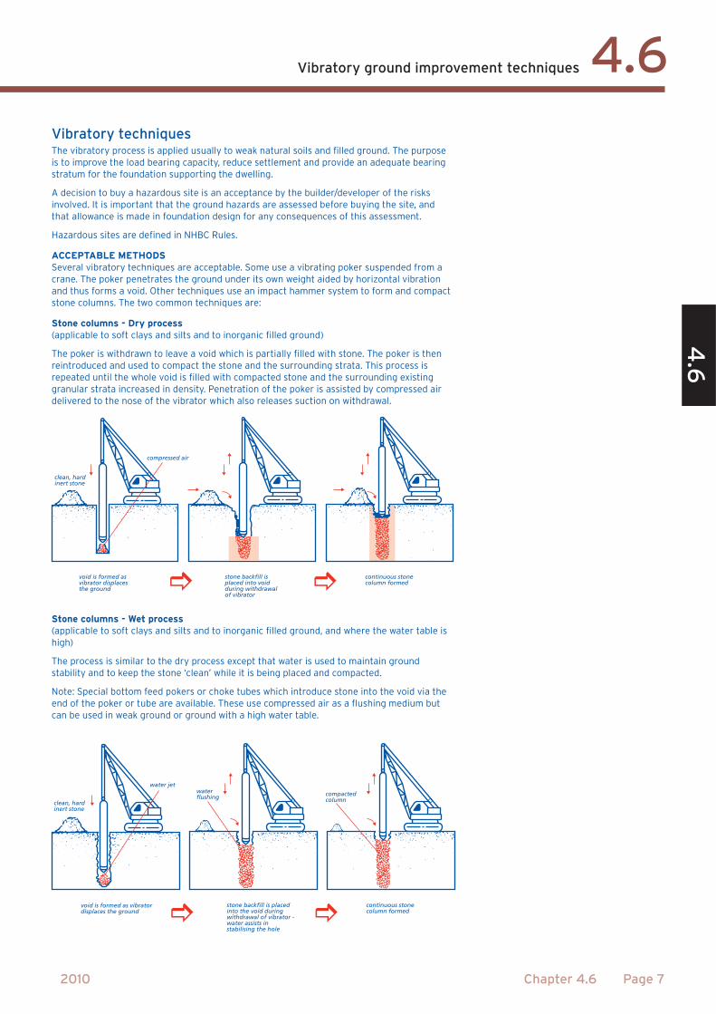
clean, hardinert stone
void is formed asvibrator displaces the ground
compressed air
stone backfill isplaced into void during withdrawalof vibrator
continuous stonecolumn formed
waterflushing
stone backfill is placedinto the void during withdrawal of vibrator - water assists instabilising the hole
continuous stonecolumn formed
clean, hardinert stone
void is formed as vibrator displaces the ground
water jet
compactedcolumn
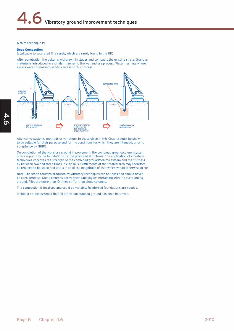
granularmaterial
compacted zone
vibrator displaces the ground
granular material is placed into the depressionaround vibrator
existing groundis compacted