Embed Size (px)
Citation preview

NASA-NGSLR-Overview
NGSLR System Overview Introduction to the NGSLR System
Jan McGarry, NASA/GSFC/694
Version 1.0 January 2014


NGSLR System Overview Preface
Document Number: P a g e | i NASA-NGSLR-Overview (v1.0)
Table of Contents
TABLE OF CONTENTS I
ACKNOWLEDGEMENTS III
1 INTRODUCTION 1
1.1 DEVELOPMENT OF THE NEXT GENERATION SYSTEM 1 1.2 DOCUMENTATION GOALS 4
2 BASIC SYSTEM OPERATION 5
2.1 SATELLITE PREDICTIONS AND SCHEDULING 5 2.2 SATELLITE LASER RANGING OPERATIONS 6 2.3 NGSLR DATA POST PROCESSING 7
3 MAIN COMPONENTS OF NGSLR 9
3.1 SHELTER AND DOME 10 3.2 TELESCOPE ASSEMBLY 12 3.3 TRACKING SUBSYSTEM 12 3.4 OPTICAL BENCH 13 3.5 LASER SUBSYSTEM 14 3.6 COMPUTER AND SOFTWARE 15 3.7 IO CHASSIS 17 3.8 TIME AND FREQUENCY 17 3.9 RANGE RECEIVER 18 3.10 WEATHER 18 3.11 LASER HAZARD REDUCTION SYSTEM (LHRS) 19
APPENDIX A: ACRONYMS 20
APPENDIX B: SYSTEM SPECIFICATIONS 21
APPENDIX C: PUBLISHED PAPERS ON NGSLR 26
APPENDIX D: ADDITIONAL REFERENCES 31

NGSLR System Overview Preface
Document Number: P a g e | i i NASA-NGSLR-Overview (v1.0)
This page intentionally left blank

NGSLR System Overview Preface
Document Number: P a g e | i i iNASA-NGSLR-Overview (v1.0)
Acknowledgements
Removed (jlfm)
The development of NGSLR (formerly SLR2000) is funded through the Science Mission Directorate at NASA Headquarters. This prototype is being developed by the Space Geodesy Project at Goddard Space Flight Center in cooperation with the
Laser Remote Sensing Laboratory, both part of the Solar System Exploration Division at Goddard.

NGSLR System Overview Preface
Document Number: P a g e | i vNASA-NGSLR-Overview (v1.0)
NGSLR during Ranging Operations
NGSLR System Overview Introduction
Document Number: P a g e | 1NASA-NGSLR-Overview (v1.0)
1 Introduction
The National Aeronautics and Space Administration (NASA) has been involved in Satellite Laser Ranging (SLR) since October 31, 1964, when the world’s first laser ranging returns from the Explorer-22 satellite (BE-B) were detected at the Goddard Optical Research Facility (now the Goddard Geophysical and Astronomical Observatory or GGAO). Since that time, NASA SLR operations have grown to include a global network of stations that track nearly 30 international spacecraft missions ranging from an altitude of 300 km to approximately 20,000 km. These stations contribute data to the International Laser Ranging Service (ILRS) where it is used to support geodetic and geophysical research. NASA’s legacy SLR systems have provided valuable data for many years, but are costly to operate and maintain, and will not be able to satisfy projected performance requirements in the near future. Budgetary constraints, increasing precision requirements, and the need to track increasing numbers of retroreflector equipped satellites are steering SLR system design toward smaller, more automated tracking systems.
The Next Generation Satellite Laser Ranging station (NGSLR) is the prototype for a semi-automated, single photon, high repetition rate satellite laser ranging station scheduled to be deployed around the world in the coming decade. It will serve as a replacement for NASA’s aging MOBLAS (MOBile LASer) and TLRS (Transportable Laser Ranging System) series SLR systems, which have been in service since the late 1970’s. Pointing precision of the NGSLR system is about 1 arcsecond. The absolute shot to shot range accuracy to LAGEOS is about 1 centimeter with a normal point (time averaged) range precision of about 1 millimeter. Additional features include semi-automated tracking, compact design, lower operation and replication costs, and increased reliability. When fully operational, the system will provide continuous, 24 hour tracking coverage to Earth orbiting satellites equipped with passive retroreflector arrays.
In addition to the normal two-way satellite laser ranging, the NGSLR system is capable of supporting other types of laser ranging, including one and two-way asynchronous transponder ranging (Degnan, 2002). Currently, the NGSLR prototype is supporting one-way laser ranging to the Lunar Reconnaissance Orbiter (LRO), an uplink only range where NGSLR records the laser fire times, and the spacecraft records the receive events. Analysts form ranges after the pass by correctly associating fires with receive events. Further details on the LRO operations at NGSLR can be found in the manual “Laser Ranging to the Lunar Reconnaissance Orbiter (LRO) from NASA’s Next Generation Satellite Laser Ranging Station” (NASA-NGSLR-OPS-LRO), or in various papers and presentations including: Zuber, et al. (2010); Mao et al. (2010); Clarke et al. (2008); Mallama (2008); McGarry et al. (2008); McGarry & Zagwodzki (2009).
1.1 Development of the Next Generation System
The original concept behind NGSLR was first proposed by John Degnan in 1994 as SLR2000, an autonomous and eye-safe SLR system. The focus of this endeavor was to develop an innovative station that could provide 24 hour tracking coverage, while reducing the cost of the SLR technique by increasing reliability, standardization and automation. This novel approach was based on over 30 years of experience developing and operating SLR systems at the Goddard Space Flight Center, and was designed to significantly reduce operations costs and possibly reduce replication costs by as much as an order of magnitude.

NGSLR System Overview Introduction
Document Number: P a g e | 2 NASA-NGSLR-Overview (v1.0)
1.1.1 Proving Design Feasibility During the first several years of NASA funding, prototypes of several critical components were developed to prove feasibility of the new concept. These included:
• A sensitive, high-speed, quadrant micro-channel plate photomultiplier for simultaneous ranging and pointing correction (Degnan 1999; McGarry, Zagwodzki, et al. 2002).
• Oscillator-only (Degnan and Zayhowski 1998) and oscillator/amplifier (Isyanova et al. 2002) versions of a multi-kilohertz microchip-laser based transmitter.
• A "smart" meteorological station which included an upgraded all-sky cloud sensor (Degnan and McGarry 1997; Mallama and Degnan 2002).
• A multi-kHz rate Range Gate Generator (Degnan, et al. 2003).
• A multi-kHz rate Event Timer with 1 mm resolution (Degnan, et al. 2003).
Once the key specifications on these advanced components were largely met, attention then turned to the detailed engineering design of the system and its components.
1.1.2 Technical Goals The following comprise the current technical goals of the system:
• Semi-autonomous operations
• 24 hours tracking of LEO, LAGEOS and GNSS satellites (with ILRS approved retro-reflectors)
• Accuracy and stability at the MOBLAS level or better
• 1 mm normal point precision on LAGEOS
• Integration of the LHRS radar for all ranging operations
• Increased reliability (Mean Time Between Failures (MBTF) > 4 months)
1.1.3 Design of the Prototype Legacy NASA SLR stations require operators to determine system viability, avoid direct contact of the laser beam with aircraft and ground personnel, and select the objects to track. The NGSLR prototype replaces much of the operator functions with automated processes. The system fires low energy pulses (~1 mJ) at a 2 kHz rate and performs single photon detection, which ensures return rates similar to those from traditional higher transmit energy, lower repetition rate SLR systems (4-10 Hz). NGSLR took a fresh approach in making the time-of-flight measurements to satellites. In the past, low repetition rate NASA systems (typically 5 Hz) operated with a single pulse in flight, enabling time interval unit measurement. Because these were single stop systems, the threshold was always set well above the noise and strong signal was always desired. For over 30 years, the NASA MOBLAS systems operated with high Signal to Noise Ratio (SNR) to prevent false detection. Supporting this philosophy of high SNR was the fact that transit time jitter of the early photomultiplier tubes (which contributed significantly to the RMS jitter) dropped off with an increase in signal. The installation of the micro-channel plate photomultiplier tubes (MCP PMTs) in NASA’s systems in the 1980’s changed the playing field significantly. The transit time jitter of the MCP PMT, even at the single photoelectron level, contributed less than 3 mm to the overall system RMS (Degnan, 1985). The implications are that systems can operate at the single photoelectron level as accurately as the multi-photon level. Hence, a SNR <1 is tolerable while enabling a reduction in laser pulse energy. In addition, the laser pulse repetition frequency (PRF) can be increased to aid in acquisition and
NGSLR System Overview Introduction
Document Number: P a g e | 3 NASA-NGSLR-Overview (v1.0)
closed loop racking. This paradigm shift in operational philosophy required the development of new instrumentation, hardware, and control algorithms to realize system operation.
One of the major challenges during the design of the system was to develop a low cost approach that could meet the above technical requirements and provide for future flexibility. This demanded using COTS/MOTS components where possible, and was implemented in several key areas such as the shelter, lasers, most of the components of the Timing and Frequency system, the Laser Hazard Reduction system (LHRS), a majority of the meteorological instrumentation, and many components on the redesigned Optical Bench.
The current system includes a more powerful COTS laser capable of ultra-short pulse/high repetition rate operation, a high bandwidth/high quantum efficiency detector, and an optical bench designed to seamlessly integrate the various automated components. Successful automation of the system includes coordinated operation of critical components such as the laser, beam blocks, ND filters, motorized optics, motorized shutters, and the star camera with the various software and hardware components that control them. The recently upgraded design has resulted in improved alignment and optical isolation, further improving the operation of the system.
For further information on the development and testing of the individual subsystems and software packages, please refer to the NGSLR references in Appendix C, many of which can be found in the Proceedings of the International Workshops on Laser Ranging. The full proceedings for all workshops can be found online at:
http://ilrs.gsfc.nasa.gov/about/reports/index.html
1.1.4 Demonstrated Tracking Capability and Data Collection The NGSLR prototype is currently operational and is located at the Goddard Geophysical and Astronomical Observatory (GGAO), which is part of NASA’s Goddard Space Flight Center (GSFC). The system routinely remains stable to within +/- 1.5 mm during hour long ground calibrations. While NGSLR is quite different from legacy NASA stations like MOBLAS and TLRS, the final data products will be the same with an accuracy that is equal to or better than those from current NASA SLR systems. Over the past year, NGSLR has taken over 280 passes of data, during both day and night tracking, demonstrating robust daylight tracking capability to retroreflector equipped satellites in low earth orbit (LEO), to LAGEOS-1 and LAGEOS-2 (~6000 km), and to GNSS satellites (~20,000 km). The system has successfully completed a collocation with MOBAS-7, demonstrating ranging agreement between systems. Details of the collocation results can be found in various presentations and papers given at the 18th International Laser Ranging Workshop in Japan (November 11-15, 2013).

NGSLR System Overview Introduction
Document Number: P a g e | 4 NASA-NGSLR-Overview (v1.0)
1.2 Documentation Goals
This document captures the configuration of the system during the collocation with MOBLAS-7 in the summer of 2013. It is intended to familiarize the reader with the NGSLR system and to serve as an aid in navigating the project documentation in a quick and efficient manner. Although available in hard copy, it is preferable to view the documentation electronically, as this will allow the reader to take advantage of software features unique to the electronic version such as embedded links, bookmarks, and topical search capability.

NGSLR System Overview Basic System Operation
Document Number: P a g e | 5 NASA-NGSLR-Overview (v1.0)
2 Basic System Operation
NGSLR is capable of automatically acquiring and tracking satellites using a set of predictions downloaded on a daily basis. The software controls the configuration of the system in various modes such as satellite tracking, ground calibration, star assessment, and star calibration. Weather, visibility, and cloud coverage are also monitored automatically by the software. These features greatly decrease the operator workload, and streamline the tracking process. The operator is still required to be on site due to laser safety requirements, as well as to interact with several systems that have yet to be automated. These tasks include manually re-enabling the laser after an aircraft has been detected, closing the dome before the onset of inclement weather, powering up/down equipment, verifying safety systems, and serving as a backup to the radar-based aircraft avoidance system, known as the LHRS. An operator control interface is provided using a laptop running the Remote Access Terminal (RAT) software, which allows the operator to adjust system parameters and modify the tracking schedule. A messaging system (Daily Diary) records the operation of the system during the last 24 hours, serving as an aid in troubleshooting system problems.
2.1 Satellite Predictions and Scheduling
NGSLR will perform day and night ranging to LEO to GNSS altitudes, with the majority of tracking coming from segments of GNSS and LAGEOS passes. LEO objects, when tracked, will typically be tracked for the full pass due to the short duration of these events. Tracking is directed and coordinated using a schedule that is developed off site and stored on the Crustal Dynamics Data Information System (CDDIS). The schedule is comprised of a seven day, satellite prioritized, interleaved list that maximizes tracking on all ILRS satellites. It lists all available targets for a site, listing a primary target to be tracked along with a set of secondary targets that can be tracked. Each satellite is assigned a tracking priority by the ILRS which typically decreases with increasing orbital altitude and orbital inclination. Adjustments to the priority are made by the ILRS for satellites that require support for active missions, post launch intensive tracking, or for missions that have greater importance within the analysis community.
Satellite predictions are available from various prediction providers, and are stored on CDDIS in the Consolidated Prediction Format (CPF). Software for NGSLR picks up the predictions from providers that are believed to be the best for each satellite. The preferred provider can change at any time and not affect the operations at NGSLR.
This schedule and the corresponding satellite predictions are retrieved at a set time during each day for use by the tracking computer. Ground calibrations are automatically interleaved between satellites in the schedule at 1 to 1 ½ hour intervals. Ground calibrations are short data segments to ground targets which measure the system delay for post processing range data correction. Star calibrations are currently selected by the operator and are performed approximately every 1 to 2 weeks (or on an as needed basis) and are used to correct the mount model to maintain accurate system pointing.

NGSLR System Overview Basic System Operation
Document Number: P a g e | 6 NASA-NGSLR-Overview (v1.0)
2.2 Satellite Laser Ranging Operations
NGSLR will spend the majority of its day acquiring and tracking satellites using the schedule. Laser Ranging occurs for scheduled passes as cloud conditions and ILRS restricted tracking parameters* permit. Exceptions include the following conditions where the dome must be closed in order to protect sensitive equipment:
• Precipitation of any kind
• Sustained gusts of greater than 40 mph (17.8 m/s)
• Temperatures that are above 122° F (50° C) or below 14° F (-10° C)
*Some missions define whether they will allow satellite tracking at a particular time. See the ILRS website for more information on tracking restrictions at: http://ilrs.gsfc.nasa.gov/
2.2.1 Data Collection Cycle NGSLR automatically follows the schedule, with the system cycling back and forth between ground calibrations and satellite passes (Figure 2-1). The schedule begins with ground calibration, followed by a 1-1 ½ hour block of passes that consist of satellites in a variety of orbital paths and altitudes. Any single pass could last from 2 minutes up to 1 hour. Regardless of the satellite, tracking is never performed below 20° in elevation due to FAA laser safety restrictions.
Figure 2-1: Typical shift showing the data collection cycle
Please note that back to back shifts do not require shutdown and startup cycles between them.
Ground Calibrations determine the system delay. This technique measures the difference between the theoretical time it should take for light to travel through the atmosphere to the target and back (as determined by the surveyed range corrected by refraction), and the time that is actually measured by the system. This system delay time is removed from satellite range measurements to produce an accurate product. In order to have an accurate estimate of the system delay, any differences in the path length between ground calibration
Initial Ground CalibrationSet of Satellite Passes
Ground CalibrationSet of Satellite Passes
Ground CalibrationSet of Satellite Passes
Ground CalibrationSet of Satellite Passes
Ground CalibrationSet of Satellite Passes
Ground CalibrationSet of Satellite Passes
Ground CalibrationSet of Satellite PassesFinal Ground Calibration
Dat
a Co
llect
ion
Power up system
Shut Down System

NGSLR System Overview Basic System Operation
Document Number: P a g e | 7 NASA-NGSLR-Overview (v1.0)
and satellite tracking must be known and accounted for. In addition, the return rate of the ground calibrations must match the return rates from the satellites.
Once the first ground calibration of the shift is complete, the system can then move on to the first set of satellite passes, tracking each according to its priority on the schedule. During the day, sun avoidance is done automatically by the system, driving the telescope around the sun or choosing another target if necessary. At night, star assessments are performed prior to nighttime satellite passes in order to provide the best acquisition probability. Upon completion of the set of passes, a final ground calibration is performed to capture the system delay. Once the data collection cycle is complete, the operator either hands it off to the next operator, or shuts down the system until the next shift.
Every 1 to 2 weeks, the system performs a star calibration to correct the mount model for accurate pointing. This requires that the system have a fairly clear nighttime sky so that enough stars can be clearly captured by the Star Camera. The system uses the Sky Camera system, which determines the clarity of the sky using an infrared image of the sky. If these criteria are met, NGSLR uses the FK5 star data file for star pointing predictions, and data received from USNO (via the iers.dut file) for Earth orientation parameters, and chooses stars between 3rd and 4th magnitudes for consistency in the star centroid calculations. The star calibration software points the telescope at each star in the list, calculates the centroid of the star, centers the star and records the biases, taking about 30-40 minutes to complete 50 stars. The system then performs a least squares fit of the bias data to the mount model to generate an updated set of mount model coefficients, which is used to correct the pointing during satellite tracking.
2.3 NGSLR Data Post Processing
The NGSLR Post Processing Software performs post tracking data processing and analysis, creation of data products, and data product delivery. Satellite data is stored until post ground calibration data has been processed. The software will then process the raw data files in the time order of their creation.
The calibration data is processed using an iterative sigma multiplier filter on range returns which have been corrected for the system delay (as calculated from recent ground calibrations) and stored in a database. The atmospheric refraction, and any optics that are in calibration path but not the satellite path, are also accounted for in the range corrections.
The satellite data post processing begins by splitting the raw data files into individual satellite pass files. The full rate observed minus calculated (O-C) range residuals are computed by subtracting the predicted range, atmospheric refraction, and system delay from the measured range. The system delay is determined by averaging the system delays from the closest in time ground calibrations before and after the satellite pass.
The pass observations are initially filtered using the real-time software’s signal flag. The signal flag is set by the on-site signal processing software and determined during the real-time tracking of the satellites. This signal is a sub-set of the all the signal returns received from the satellite. The post-processing software starts with the real-time returns, and then includes all returns in a range space window and time (epoch) space window near the real-time signal. The process ensues that nearly all potential signal returns are included in the analysis while eliminating obvious noise returns.

NGSLR System Overview Basic System Operation
Document Number: P a g e | 8 NASA‐NGSLR‐Overview (v1.0)
This set of observations is input into the normal point software. The normal point software’s main function is to generate the ILRS data product (CRD normal points). The normal points are formed by first generating full rate residuals from a predicted satellite orbit, then smoothing and filtering the residuals using various techniques including an iterative least squares polynomial. After the residuals have been filtered, the normal points are formed by averaging the accepted range observations in each normal point time bin and time tagging the normal with the median time observation in the bin. Normal points that pass quality control standards are output in the CRD format, compressed and delivered to the ILRS data center once per hour. The full rate observations used to generate the normal points are also output in the CRD format, but are retained at GGAO for future reference.
Figure 2‐2: Diagram illustrating the flow of ranging data
CentralFacility
10
6
1
Event Timer
2
ANA
Discriminator
PMT
Telescope
3
NFS share
NFS share
ICC ↔ POP
Shared Memory*
POP ↔ DAM
Shared Memory*
POPICC DAM
5 7 8
9
Key
Data
RemoteConnectivity
11
12
CDDIS
*Note: Diagram illustrates different locations within the same shared memory system.
4
1. Laser returns along with background noise arrive through the telescope. 2. PMT detects photon(s) and sends analog signal to the discriminator. 3. Discriminator converts the analog signal to a logic pulse and sends it to the Event Timer. 4. ICC reads values from the Event Timer buffer every 500μs. 5. ICC sends data to POP every 500μs. 6. POP collects the data from ICC and stores in a circular buffer. 7. POP performs signal processing on the data in the circular buffer every frame (4 to 30 seconds, satellite dependent). 8. POP appends data from each frame to a unique set of logx_*.asc and logx*.bin files under the /logx directory. 9. Once logging is completed (may be multiple passes), POP puts the name of the logx file in shared memory and sets the data ready flag. 10. The overseer program, running on DAM, uses the name of the logx file to create a blank logx file on its NFS share. 11. Running on ANA, process_log monitors DAM’s NFS share for new files, indicating that a logx file is ready to be copied from the POP Network File System (NFS) share. 12. The actual logx file is copied to ANA and processing begins. 13. Once processing is complete, *.npt files are sent to a central facility where the data is collected up and sent on to CDDIS.

NGSLR System Overview Main Components of NGSLR
Document Number: P a g e | 9 NASA‐NGSLR‐Overview (v1.0)
3 Main Components of NGSLR
The NGSLR prototype can be divided into eleven major subsystems that perform unique functions within the system (Figure 3‐1). Control of the system is centralized in the Computer and Software system, which provides a console for an operator via a graphical user interface. Each subsystem, along with a brief introduction, is listed below. These include:
1) Shelter and Dome 2) Telescope 3) Tracking Subsystem 4) Optical Bench 5) Laser Subsystem 6) Computer and Software
7) IO Chassis 8) Time & Frequency 9) Range Receiver 10) Weather 11) Laser Hazard Reduction System (LHRS)
Details on all of these subsystems can be found in the NGSLR Hardware Manual (NASA‐NGSLR‐HWR‐Manual).
Figure 3‐1 (below) illustrates the interconnectivity of the system and the delegation of responsibilities among the devices.
Figure 3‐1: The eleven major systems of NGSLR
Computers and Software6
Receiver
Weather
Optical Bench4
IO Chassis
Shelter and Dome
Laser(s)5
LHRS11
Tracking3
Telescope
Timing8
1
7
9
10
2

NGSLR System Overview Main Components of NGSLR
Document Number: P a g e | 1 0 NASA-NGSLR-Overview (v1.0)
3.1 Shelter and Dome
The shelter is a modular structure that provides a temperature controlled environment for the equipment (Figures 3-2 and 3-3). It supports a motorized, 10’ diameter, fiberglass observatory dome which protects the telescope and gimbal system. The dome rotates with the telescope, as the azimuth control system is slaved to the telescope via the software. Access to the telescope and dome is provided by a stairway accessible catwalk mounted on top of the shelter.
Figure 3-2: Front of NGSLR Shelter and Dome
Figure 3-3: Back ¾ view of the NGSLR Shelter

NGSLR System Overview Main Components of NGSLR
Document Number: P a g e | 1 1 NASA-NGSLR-Overview (v1.0)
The interior is divided up into two major sections, the control area and the laser operations area as shown in Figure 3-4. The control area allows authorized personnel access to the operator console and the equipment rack without requiring eye protection during operations (Figure 3-5). The laser operations area is an enclosed area for the optical bench which confines stray laser energy and assists in maintaining a clean environment for the optics. Personnel in this area are required to wear eye protection when the laser is operational. Air within this area is maintained at a slight positive pressure to discourage the entry of unfiltered air.
Figure 3-4: Layout of the NGSLR Shelter
Figure 3-5: View of the Operator Console
Control Area
Laser Operations Area
Control Area
Nominal Hazard Zone (NHZ)
NGSLR System Overview Main Components of NGSLR
Document Number: P a g e | 1 2 NASA-NGSLR-Overview (v1.0)
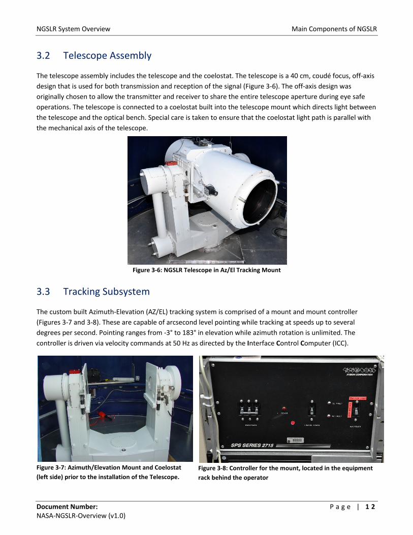
3.2 Telescope Assembly
The telescope assembly includes the telescope and the coelostat. The telescope is a 40 cm, coudé focus, off-axis design that is used for both transmission and reception of the signal (Figure 3-6). The off-axis design was originally chosen to allow the transmitter and receiver to share the entire telescope aperture during eye safe operations. The telescope is connected to a coelostat built into the telescope mount which directs light between the telescope and the optical bench. Special care is taken to ensure that the coelostat light path is parallel with the mechanical axis of the telescope.
Figure 3-6: NGSLR Telescope in Az/El Tracking Mount
3.3 Tracking Subsystem
The custom built Azimuth-Elevation (AZ/EL) tracking system is comprised of a mount and mount controller (Figures 3-7 and 3-8). These are capable of arcsecond level pointing while tracking at speeds up to several degrees per second. Pointing ranges from -3° to 183° in elevation while azimuth rotation is unlimited. The controller is driven via velocity commands at 50 Hz as directed by the Interface Control Computer (ICC).
Figure 3-7: Azimuth/Elevation Mount and Coelostat (left side) prior to the installation of the Telescope.
Figure 3-8: Controller for the mount, located in the equipment rack behind the operator

NGSLR System Overview Main Components of NGSLR
Document Number: P a g e | 1 3 NASA-NGSLR-Overview (v1.0)
3.4 Optical Bench
The optical bench maintains the position, spacing, and alignment of all the optical components before the coelostat (Figure 3-9). Devices include the laser head(s), turning mirrors, lenses, prisms and other similar items related to the transmission and detection of the laser. Several devices on the optical bench are controlled remotely by the DAM computer and adjust the point-ahead of the laser transmitter, the band pass filter, the rotary ND wheels and the receiver field of view. Automated safety devices such as beam blocks, shutters, and ND filters (for ground calibration) are also situated on the SLR optical bench, controlled by the IO Chassis (See Section 3.7).
Figure 3-9: View of the SLR Optical Bench during development

NGSLR System Overview Main Components of NGSLR
Document Number: P a g e | 1 4 NASA-NGSLR-Overview (v1.0)
3.5 Laser Subsystem
The NGSLR system uses different lasers for SLR and LRO operations. The SLR laser is a pulsed 532 nm laser used for two-way ranging to satellites (Figure 3-10). The 2 kHz repetition rate is adjusted over a narrow range to avoid interference between the outgoing and incoming light at the sensitive single photon detector. SLR laser output energy at the laser is 1.0 mJ/pulse, with a pulse width of 50 ps (FWHM). The LRO laser, used for one-way ranging to the Lunar Reconnaissance Orbiter, is a 28 Hz / 532.2 nm laser with a 5.5 ns pulse-width and an output energy at the laser of ~ 40 mJ/pulse (Figure 3-11). It is inserted into the telescope optical system after the SLR laser optics and thus is unaffected by changes to the SLR optical bench.
Figure 3-10: SLR Laser as installed on the SLR Optical Bench
Figure 3-11: LRO Laser and LRO Optical Table mounted on the Telescope Pier above the SLR
Optical Bench

NGSLR System Overview Main Components of NGSLR
Document Number: P a g e | 1 5 NASA‐NGSLR‐Overview (v1.0)
3.6 Computer and Software
Numerous computers control the NGSLR system. These include: the Interface Control Computer (ICC), the Pseudo Operator (POP), the Device Access Manager (DAM), the data Analysis computer (ANA), the Camera computer (CAM), and the Remote Access Terminal (RAT) (Figure 3‐12).
Figure 3‐12: The six main computers that comprise the NGSLR computer system
3.6.1 Interface Control Computer (ICC) The ICC performs real‐time input and output functions to hardware devices via interface cards. No data processing is actually performed on the ICC; all data is passed to and from POP via shared memory. This DOS based system runs on a Pentium class processor with a mixed ISA/PCI bus. Software tasking is driven by 2 kHz interrupts from the timing system via a timing and digital interface card.
3.6.2 Pseudo Operator Computer (POP) POP makes most of the operator decisions, controls the VME hardware interface to the IO Chassis, and passes data to and from DAM via NFS and shared memory. As with the ICC, the software tasking is driven by a 2 kHz interrupt from the timing system. POP runs under LynxOS on a single board Pentium computer hosted on the VMEbus Chassis.
3.6.3 Device Access Manager Computer (DAM) DAM is responsible for controlling the motorized optics on the SLR optical bench, providing an area for ANA to deposit predictions and schedules from the remote Central Facility (which will be utilized by POP), hosting a remote interface for the RAT system and collecting meteorological information. DAM operates under LynxOS on a single board Pentium computer hosted by the VME bus Chassis.

NGSLR System Overview Main Components of NGSLR
Document Number: P a g e | 1 6 NASA‐NGSLR‐Overview (v1.0)
3.6.4 Data Analysis Computer (ANA) ANA, the data analysis computer, is responsible for post processing and data delivery. Ranging data is sent through three processing systems: Calibration, Satellite, and Normal Point, which produce the final data product in ILRS Normal Point format. These files are uploaded to a central distribution facility on an hourly basis for use by the scientific community. ANA runs on a desktop computer using Fedora Linux.
3.6.5 Remote Access Terminal RAT allows one operator to remotely control, configure and troubleshoot all major systems over the NASA intranet. The RAT software resides on a laptop running Fedora Linux, and allows the operator to display data graphically on the monitor, and run the NGSLR system. RAT connects through a secure internet connection to a service on DAM, which provides access to information on the other NGSLR systems.
3.6.6 Camera Computer The Camera computer is a Windows XP (SP3) based system which configures the SLR laser for alignment or tracking operation, controls the beam profiler, and controls the two camera systems used on NGSLR (the Sky and Star cameras). Images from these cameras are passed to the other NGSLR computers via NFS mounted files. In addition, the Camera computer also displays the LRO‐LR real‐time website, used by operators during LRO operations. The SLR laser is configured for operation using a custom software package developed to simplify operation of the laser. The beam profiler is operated using GUI based software provided by the manufacturer, while the two cameras are controlled by custom software written by the NGSLR development team. The first camera is a CCD that is mounted on the SLR optical bench and is used to perform star calibrations. The second, a thermal infrared camera located outside of the NGSLR facility, is used to determine cloud cover over the full hemispherical sky.
Figure 3‐13: NGSLR Computer System Connectivity Diagram
POP DAM
Ratsnest
RAT is connected to on DAM via
Ethernet
CentralFacility
Cameracomputer
Ethernet
Analysis Computer (ANA)
(Post Processing Analysis)
ICC
Key
Data ConnectionEthernet
Off-SiteConnectivity
Remote AccessTerminal (RAT)
ICC/POP
Shared Memory:POP/DAN/RAT *
Timing8
Shelter and Dome1
Weather10
Optical Bench4
IO Chassis7
LHRS11
6
Shared Memory:ICC/POP *
Computers and Software
Ratsnest
x
Tracking3
Lasers5
Receiver9
Telescope2
System Identifier
NGSLR System Overview Main Components of NGSLR
Document Number: P a g e | 1 7 NASA-NGSLR-Overview (v1.0)
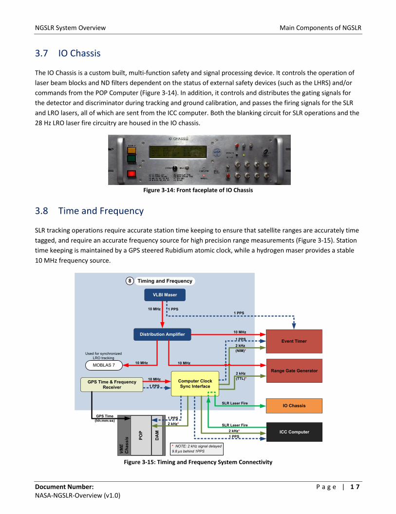
3.7 IO Chassis
The IO Chassis is a custom built, multi-function safety and signal processing device. It controls the operation of laser beam blocks and ND filters dependent on the status of external safety devices (such as the LHRS) and/or commands from the POP Computer (Figure 3-14). In addition, it controls and distributes the gating signals for the detector and discriminator during tracking and ground calibration, and passes the firing signals for the SLR and LRO lasers, all of which are sent from the ICC computer. Both the blanking circuit for SLR operations and the 28 Hz LRO laser fire circuitry are housed in the IO chassis.
Figure 3-14: Front faceplate of IO Chassis
3.8 Time and Frequency
SLR tracking operations require accurate station time keeping to ensure that satellite ranges are accurately time tagged, and require an accurate frequency source for high precision range measurements (Figure 3-15). Station time keeping is maintained by a GPS steered Rubidium atomic clock, while a hydrogen maser provides a stable 10 MHz frequency source.
Figure 3-15: Timing and Frequency System Connectivity
POP
DA
M
VME
Cha
ssis
Event Timer
IO Chassis
Range Gate Generator
Distribution Amplifier
Computer Clock Sync Interface
GPS Time & Frequency Receiver
GPS Time(hh:mm:ss)
10 MHz
10 MHz
1 PPS
8 Timing and Frequency
10 MHz
ICC ComputerSLR Laser Fire
SLR Laser Fire
2 kHz*
2 kHz (TTL)*
2 kHz (NIM)*
2 kHz*
1 PPS
MOBLAS 7
Used for synchronized LRO tracking
* NOTE: 2 kHz signal delayed 9.8 µs behind 1PPS
1 PPS
VLBI Maser
10 MHz 1 PPS
1 PPS
10 MHz
1 PPS

NGSLR System Overview Main Components of NGSLR
Document Number: P a g e | 1 8 NASA-NGSLR-Overview (v1.0)
3.9 Range Receiver
The Range Receiver subsystem detects and time tags returns, provides gating for the detector, and controls the programmable delays for the system. Critical components include a micro-channel plate photomultiplier tube, signal amplifier, timing discriminator, Event Timer (ET), gating module and the Range Gate Generator (RGG) as shown on Figure 3-16. These components form an essential part of the signal detection system where synchronization is crucial to proper system operation.
Figure 3-16: Range Receiver Block Diagram
3.10 Weather
The weather system uses COTS meteorological instruments that measure pressure, temperature, relative humidity, precipitation, horizontal visibility, and wind velocity (Figure 3-17). Pressure, temperature, and relative humidity readings are used to compute atmospheric corrections to the measured range based on the Marini-Murray model (Marini and Murray, 1973). In addition, the weather system hosts the Sky Camera, an in-house developed, thermal infrared instrument which monitors cloud cover and determines whether tracking is possible in a particular region of the sky (Mallama and Degnan, 2002).
Figure 3-17: Overhead layout of weather instrumentation
IrisControls field
of viewAmplifierPhillips Scientific 774
DiscriminatorTennelec TC454 CFD
Channel 1
Channel 2
Channel 3
Channel 4 Event Timer (ET)CH 3
RGGJ5I/O Chassis J16J8+12 V TTL
High Voltage Power Supply
(Bertran Model 315)
Gating Module
TTL
-2950 V
Hamamatsu
Gate
- HV
NIMPhoton
Building 201
NGSLR
LHRSLaser Hazard Reduction System
Paved Access Road
Parking Area
Sky Camera
Precipiation Sensor
Weather InstrumentsTemperature, Wind Speed,
Pressure and Humidity

NGSLR System Overview Main Components of NGSLR
Document Number: P a g e | 1 9 NASA-NGSLR-Overview (v1.0)
3.11 Laser Hazard Reduction System (LHRS)
The Laser Hazard Reduction System (LHRS) is a laser safety radar system needed for aircraft avoidance. Housed on an elevated platform approximately 30 feet from NGSLR, the radar is slaved to the pointing of the telescope and the laser (Figure 3-18). When an aircraft is detected within a 3 degree diameter cone surrounding the laser beam, a beam block is activated to interrupt the laser transmit path, effectively cutting off the transmission of the beam (Figure 3-19). Due to FAA regulations, the insertion of the beam block must be manually acknowledged by the operator after each occurrence in order to re-enable the transmission of the laser. The radar operates in an environmentally controlled dome, as directed by a control unit located in the NGSLR shelter.
Figure 3-18: The NGSLR shelter (left) with the LHRS tower on the right
Figure 3-19: Conceptual diagram of the cone of radar energy from the LHRS that surrounds the laser

NGSLR System Overview Appendix A: Acronyms
Document Number: P a g e | 2 0 NASA-NGSLR-Overview (v1.0)
Appendix
Appendix A: Acronyms
Acronym Definition AZ/EL Azimuth/Elevation CCD Charge Coupled Device CDDIS Crustal Dynamics Data Information System COTS Commercial Off The Shelf CPF Consolidated Prediction Format CRD Consolidated Laser Ranging Data Format FAA Federal Aviation Administration FWHM Full Width at Half Maximum GGAO Goddard Geophysical and Astronomical Observatory GNSS Global Navigation Satellite System GPS Global Positioning System GUI Graphical User Interface ILRS International Laser Ranging Service IO Input / Output ISA Industry Standard Architecture LAGEOS Laser Geodynamics Satellite LEO Low Earth Orbit LHRS Laser Hazard Reduction System LRO Lunar Reconnaissance Orbiter LRO-LR Lunar Reconnaissance Orbiter - Laser Ranging MCP Micro-Channel Plate MOBLAS Mobile Satellite Laser Ranging System MOTS Modified Off The Shelf MTBF Mean Time Between Failure ND Neutral Density NFS Network File System NGSLR Next Generation Satellite Laser Ranging PCI Peripheral Component Interconnect PMT Photo Multiplier Tube PRF Pulse Repetition Frequency RMS Root Mean Square SLR Satellite Laser Ranging SNR Signal to Noise Ratio TLRS Transportable Laser Ranging System USNO United States Naval Observatory
NGSLR System Overview Appendix B: System Specifications
Document Number: P a g e | 2 1 NASA-NGSLR-Overview (v1.0)
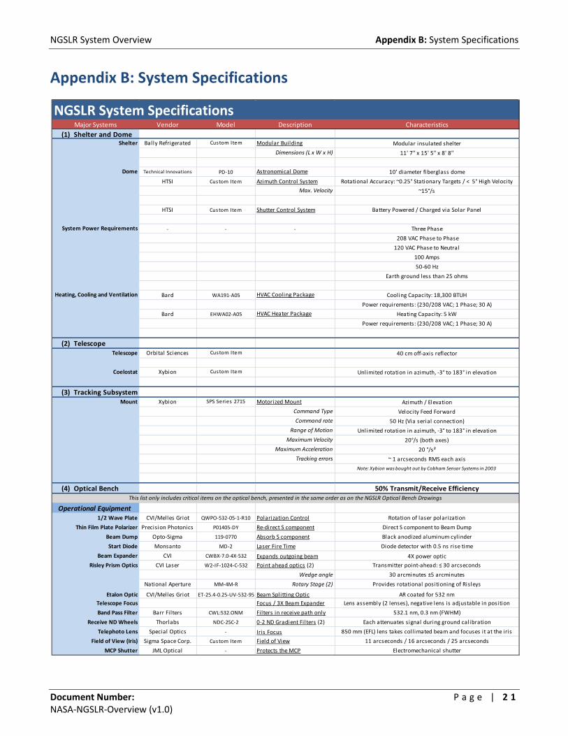
Appendix B: System Specifications
NGSLR System SpecificationsMajor Systems Vendor Model Description Characteristics
(1) Shelter and DomeShelter Bally Refrigerated
Custom Item Modular Building Modular insulated shelter
Dimensions (L x W x H) 11' 7" x 15' 5" x 8' 8"
Dome Technical Innovations PD-10 Astronomical Dome 10' diameter fiberglass dome
HTSI Custom Item Azimuth Control System Rotational Accuracy: ~0.25° Stationary Targets / < 5° High Velocity
Max. Velocity ~15°/s
HTSI Custom Item Shutter Control System Battery Powered / Charged via Solar Panel
System Power Requirements - - - Three Phase
208 VAC Phase to Phase
120 VAC Phase to Neutral
100 Amps
50-60 Hz
Earth ground less than 25 ohms
Heating, Cooling and Ventilation Bard WA191-A05 HVAC Cooling Package Cooling Capacity: 18,300 BTUH
Power requirements: (230/208 VAC; 1 Phase; 30 A)
Bard EHWA02-A05 HVAC Heater Package Heating Capacity: 5 kW
Power requirements: (230/208 VAC; 1 Phase; 30 A)
(2) Telescope Telescope Orbital Sciences Custom Item 40 cm off-axis reflector
Coelostat Xybion Custom Item Unlimited rotation in azimuth, -3° to 183° in elevation
(3) Tracking SubsystemMount Xybion SPS Series 2715 Motorized Mount Azimuth / Elevation
Command Type Velocity Feed Forward
Command rate 50 Hz (Via serial connection)
Range of Motion Unlimited rotation in azimuth, -3° to 183° in elevation
Maximum Velocity 20°/s (both axes)
Maximum Acceleration 20 °/s²Tracking errors ~ 1 arcseconds RMS each axis
Note: Xybion was bought out by Cobham Sensor Systems in 2003
(4) Optical Bench 50% Transmit/Receive Efficiency
Operational Equipment1/2 Wave Plate CVI/Melles Griot QWPO-532-05-1-R10 Polarization Control Rotation of laser polarization
Thin Film Plate Polarizer Precision Photonics P01405-DY Re-direct S component Direct S component to Beam Dump
Beam Dump Opto-Sigma 119-0770 Absorb S component Black anodized aluminum cylinder
Start Diode Monsanto MD-2 Laser Fire Time Diode detector with 0.5 ns rise time
Beam Expander CVI CWBX-7.0-4X-532 Expands outgoing beam 4X power optic
Risley Prism Optics CVI Laser W2-IF-1024-C-532 Point ahead optics (2) Transmitter point-ahead: ≤ 30 arcseconds
Wedge angle 30 arcminutes ±5 arcminutes
National Aperture MM-4M-R Rotary Stage (2) Provides rotational positioning of Risleys
Etalon Optic CVI/Melles Griot ET-25.4-0.25-UV-532-95 Beam Splitting Optic AR coated for 532 nmTelescope Focus Focus / 3X Beam Expander Lens assembly (2 lenses), negative lens is adjustable in position
Band Pass Filter Barr Filters CWL:532.ONM Filters in receive path only 532.1 nm, 0.3 nm (FWHM)
Receive ND Wheels Thorlabs NDC-25C-2 0-2 ND Gradient Filters (2) Each attenuates signal during ground calibration
Telephoto Lens Special Optics - Iris Focus 850 mm (EFL) lens takes coll imated beam and focuses it at the iris
Field of View (Iris) Sigma Space Corp. Custom Item Field of View 11 arcseconds / 16 arcseconds / 25 arcseconds
MCP Shutter JML Optical - Protects the MCP Electromechanical shutter
This list only includes critical items on the optical bench, presented in the same order as on the NGSLR Optical Bench Drawings

NGSLR System Overview Appendix B: System Specifications
Document Number: P a g e | 2 2 NASA-NGSLR-Overview (v1.0)
NGSLR System SpecificationsMajor Systems Vendor Model Description Characteristics
Alignment EquipmentWide field of view Camera WATEC WAT-902H Alignment Aid Able to view the full telescope FOV
Star Camera Beam Reducer Special Optics 52-25-5XA-532/1064 Reduces Star Field Image Reduces beam to a size usable by the Star Camera
Star Camera Shutter JML Optical - Protects the Star Camera Electromechanical shutter
Star Camera SBIG ST-402ME Focus and Alignment CCD camera used for system alignment and focus reference
Description Low noise, high QE camera
Lens 1" focal length lens for the Star Camera
CCD Size 765 x 510 pixels
Sensitivity < 8th magnitude stars
Interface USB 2.0
Auto Collimator Keuffel & Esser 71-2022 Coll imated Light Source Used by the Star Camera as the focus reference for the system
(5) Laser SubsystemSLR Laser Photonics Industries RGL-532-2.5 Used for SLR Operations Main SLR Laser, two way ranging
Wavelength Doubled Nd:YAG (532 nm)
Polarization Horizontal (Ratio >100:1)
Variable (Optimized for 2 kHz)
Pulse Width ~50 ps (FWHM)
Pulse to pulse stabil ity < 2% RMS
Maximum Pulse Energy ~2.8 mJ/pulse
~5.6 W
Operating Pulse Energy 1 mJ/pulse
2 W
Beam Diameter ~2.5 mm
Full-Angle Far-Field Divergence 0.9 mrad
Pointing Stability 4.6 µrads, 7.8 µrads (x,y)
M 2 1.47
LRO Laser Northrop Grumman NPL-002-QTGP-0010 Used for LRO Operations LRO Laser, one way ranging
Wavelength Doubled Nd:YAG (532 nm)
Polarization Linear
Fire Rate 28 Hz
Pulse Width 5.5 ns (FWHM)
Maximum Pulse Energy 50 mJ/pulse
1.4 W
Operating Pulse Energy 40 mJ/pulse
1.12 W
Beam Diameter 9 mm
Full-Angle Divergence <1.6 mrad
(6) Computers/SW VME Chassis GE/FANUC - Main Chassis 6U Double slot Eurocard format
GE/FANUC 7851RC Card Pseudo Operator System automation, data handling and coordination
Operating System LynxOS
Processor Pentium IV (2.2 GHz)
RAM/HD 1 GB SDRAM/60 GB (IDE)
GE/FANUC 7851RC Card Device Access Manager Device management and control
Operating System LynxOS
Processor Pentium IV (2.2 GHz)
RAM/HD 1 GB SDRAM/60 GB (IDE)
GE/FANUC 7459 Card Additional Storage(2) Single slot CD-RW (IDE) and 80 GB hard drive (IDE)
GE/FANUC S810 Card PCI-VME Bus Adapter PCI-VME bus adapter via single mode fiber
GE/FANUC 400-206 Card Dual Port 8 MB RAM Optional memory card for S810
GE/FANUC 6015 Card Serial Port Expansion(3) Hosts (4) serial ports per card
GE/FANUC 2510b Card Parallel I/O Hosts (2) 64-pin DIN connectors
GE/FANUC 4514a Card Analog/Digital I/O 16 channel, 12 bit analog I/O card with analog to digital converter
Maximum Average Power @ 28 Hz
Average Operating Power@ 28 Hz
Average Operating Power@ 2 kHz
Fire Rate
Maximum Average Power @ 2 kHz
NGSLR System Overview Appendix B: System Specifications
Document Number: P a g e | 2 3 NASA-NGSLR-Overview (v1.0)
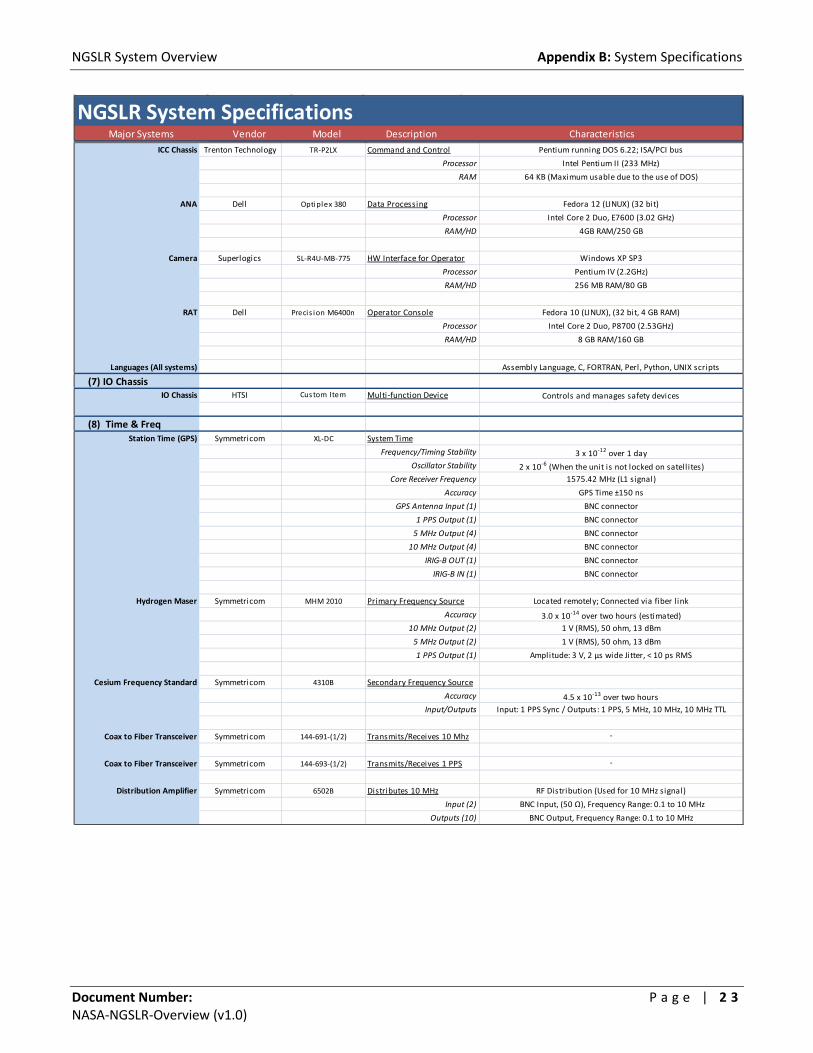
NGSLR System SpecificationsMajor Systems Vendor Model Description Characteristics
ICC Chassis Trenton Technology TR-P2LX Command and Control Pentium running DOS 6.22; ISA/PCI bus
Processor Intel Pentium II (233 MHz)
RAM 64 KB (Maximum usable due to the use of DOS)
ANA Dell Optiplex 380 Data Processing Fedora 12 (LINUX) (32 bit)
Processor Intel Core 2 Duo, E7600 (3.02 GHz)
RAM/HD 4GB RAM/250 GB
Camera Superlogics SL-R4U-MB-775 HW Interface for Operator Windows XP SP3
Processor Pentium IV (2.2GHz)
RAM/HD 256 MB RAM/80 GB
RAT Dell Precis ion M6400n Operator Console Fedora 10 (LINUX), (32 bit, 4 GB RAM)
Processor Intel Core 2 Duo, P8700 (2.53GHz)
RAM/HD 8 GB RAM/160 GB
Languages (All systems) Assembly Language, C, FORTRAN, Perl, Python, UNIX scripts
(7) IO ChassisIO Chassis HTSI Custom Item Multi-function Device Controls and manages safety devices
(8) Time & FreqStation Time (GPS) Symmetricom XL-DC System Time
Frequency/Timing Stability 3 x 10-12 over 1 dayOscillator Stability 2 x 10⁻⁶ (When the unit is not locked on satell ites)
Core Receiver Frequency 1575.42 MHz (L1 signal)
Accuracy GPS Time ±150 ns
GPS Antenna Input (1) BNC connector
1 PPS Output (1) BNC connector
5 MHz Output (4) BNC connector
10 MHz Output (4) BNC connector
IRIG-B OUT (1) BNC connector
IRIG-B IN (1) BNC connector
Hydrogen Maser Symmetricom MHM 2010 Primary Frequency Source Located remotely; Connected via fiber l ink
Accuracy 3.0 x 10⁻¹⁴ over two hours (estimated)10 MHz Output (2) 1 V (RMS), 50 ohm, 13 dBm
5 MHz Output (2) 1 V (RMS), 50 ohm, 13 dBm
1 PPS Output (1) Amplitude: 3 V, 2 μs wide Jitter, < 10 ps RMS
Cesium Frequency Standard Symmetricom 4310B Secondary Frequency Source
Accuracy 4.5 x 10⁻¹³ over two hoursInput/Outputs Input: 1 PPS Sync / Outputs: 1 PPS, 5 MHz, 10 MHz, 10 MHz TTL
Coax to Fiber Transceiver Symmetricom 144-691-(1/2) Transmits/Receives 10 Mhz -
Coax to Fiber Transceiver Symmetricom 144-693-(1/2) Transmits/Receives 1 PPS -
Distribution Amplifier Symmetricom 6502B Distributes 10 MHz RF Distribution (Used for 10 MHz signal)
Input (2) BNC Input, (50 Ω), Frequency Range: 0.1 to 10 MHz
Outputs (10) BNC Output, Frequency Range: 0.1 to 10 MHz

NGSLR System Overview Appendix B: System Specifications
Document Number: P a g e | 2 4 NASA-NGSLR-Overview (v1.0)
NGSLR System SpecificationsMajor Systems Vendor Model Description Characteristics
(9) Range ReceiverDetector Hamamatsu R5916U-64 Signal Photon Detector Microchannel Plate Photomultiplier Tube (MCP PMT)
Quantum Efficiency 25% (min), 35% (typ), 42% (as measured)
Rise Time 200 ps mm
Fall Time 700 ps
I.R.F (FWHM) 110 ps
Supply Voltage -2800 to -3000
Amplifier Phill ips Scientific 774 Signal Amplifier Fast rise time amplifier
Wideband Performance 100 KHz to 1.8 GHz
Fixed Voltage Gain 50
Rise time 180 psec
Insertion Delay Typically 1.0 nsec
Note: Information from 2009 manual
Discriminator Tennelec TC 454 SLR Signal Discriminator Constant Fraction Discriminator
Count rate capability 200 MHz
Dynamic Range 1000:1
Typical Walk ±30 ps for 100:1 Dynamic Range
Note: Company now owned by Canberra; Information from 2009 manual
Discriminator Phill ips Scientific 6915 LRO Signal Discriminator Constant Fraction Discriminator
Event Timer HTSI Custom Item Time-tag Events
Resolution 1.5 ps
RMS 30 ps
Deadtime 50 nsec
Inputs [NIM] (12) SMA connector
Other Inputs 10 MHz, 2 kHz, 1 PPS
Range Gate Generator HTSI Custom Item Controls Programmable Delays
Precision 30 ps
Step 30 ps
TTL Channels (4) SMA connector
NIM Channels (2) SMA connector
Inputs 2 kHz, 10 MHz
(10) WeatherPressure/Temp./Humidity Paroscientific MET4 Measurement Accuracy
Pressure ±0.08 hPa from 500 hPa to 1100 hPa
Temperature ±0.2 °C from -50°C to +60°C
Humidity ±2% Humidity at 25°C
Wind Belfort/Young Model 05103 Measurement Accuracy
Wind Speed 0-100 m/s ±0.3 m/s
Wind Direction 360° ± 3°
Precipitation/Visibility Vaisala Model FD12P Measurement Accuracy
Visibility Measurement Threshold of Detection
Intensity
10 m - 50 km 0.05 mm/h (within 10 min)
0-999 mm/h
SkyCamera Jenoptik VarioCAM Specifications Infrared (8-13 μm) Camera in NEMA 4 enclosure
Detector 320 x 240 pixel resolution
Image Coverage 1.3° of the sky per pixel, down to 10° Elevation
Calibration -50°C to 100°C (special order)
Interface Fire Wire (IEEE 1394)
PerkinElmer Custom Item Hemispherical Mirror Rhodium coating (0.050-0.060 in thick)

NGSLR System Overview Appendix B: System Specifications
Document Number: P a g e | 2 5 NASA-NGSLR-Overview (v1.0)
NGSLR System SpecificationsMajor Systems Vendor Model Description Characteristics
(11) LHRSLaser Hazard Reduction System HTSI LHRS Radar
Type Azimuth / Elevation
Azimuth Range Unlimited
Elevation Range -2° through 182°
Maximum Slew Velocity ~15°/s
Transmitter Center Frequency 9410 MHz ±30 MHz
Minimum Detection Range ~200 m
Maximum system capability for target detection ~42 km for a 20 m² target (calculated value)

NGSLR System Overview Appendix C: Published Papers on NGSLR
Document Number: P a g e | 2 6 NASA-NGSLR-Overview (v1.0)
Appendix C: Published Papers on NGSLR
Appleby, G., G. Kirchner, J. McGarry, T. Murphy, C. Noll, E. Pavlis, and M. Pearlman. (2010). “Current Trends in Satellite Laser Ranging.” American Geophysical Union, Fall Meeting, San Francisco, California, December 13-17. Abstract: G14B-05.
Bauer, S., J. Oberst, H. Hussmann, P. Glaser, U. Schreiber, D. Mao, G. Neumann, et al. (2012). “Reduction and analysis of one-way laser ranging data from Wettzell ground station to LRO.” International Technical Laser Workshop 2012, Frascati, Italy, November 5-9.
Behrend, D., J. Gipson, C. Ma, and J. McGarry. (2011). “GGAO as an Integrated Geodetic Site.” European Geosciences Union: Spring Meeting, Vienna, Austria, April 3-8. Abstract: EGU2011-14126.
Clarke, C., J. Degnan, J. McGarry, and E. Pavlis. “Processing Single Photon Data for Maximum Range Accuracy.” 18th International Laser Ranging Workshop, Fujiyoshida, Japan, November 11-15. Abstract: 13-0413.
Clarke, C., J. Horvath, J. McGarry, C. Noll, D. Carter, G. Neumann, and M. Torrence. (2008). “Laser Ranging (LR) Lunar Reconnaissance Orbiter (LRO) Data Flow and Scheduling.” Proceedings of the 16th International Laser Ranging Workshop, Poznan, Poland, October 12-17.
Degnan, J. (2000). “An Overview of SLR2000: Engineering Progress and Potential Future Upgrades.” Proceedings of the 12th International Workshop on Laser Ranging, Matera, Italy, November 13-17.
Degnan, J. (1999). "Engineering Progress on the Fully Automated, Photon-Counting SLR2000 Satellite Laser Ranging Station.” Laser Radar Ranging and Atmospheric Lidar Techniques II, Europto Proceedings, Vol. 3865, Florence, Italy, September 20-21: pp. 75-82.
Degnan, J. (2002). “Optimization of the Correlation Range Receiver Parameters in SLR2000.” Proceedings of the 13th International Workshop on Laser Ranging, Washington, DC, October 7-11.
Degnan, J. (2008). “Ray Matrix Analysis for the Real Time Control of Automated SLR2000 Optical Subsystems.” Technical Report (Revised), Sigma Space Corporation, Lanham, MD.
Degnan, J. (1985). “Satellite Laser Ranging: Current Status and Future Prospects.” IEEE Transactions on Geoscience and Remote Sensing, GE-23: pp. 398-413.
Degnan, J. (2002). "SLR2000: Progress and Future Applications.” Proceedings of the 13th International Workshop on Laser Ranging, Washington, DC, October 7-11.
Degnan, J. (1998). "SLR2000 Project: Engineering Overview and Status.” Proceedings of the 11th International Workshop on Laser Ranging, Deggendorf, Germany, September 21-25.
Degnan, J., and D. Caplan. (2006). “Performance of a Liquid Crystal Optical Gate for Suppressing Laser Backscatter In Monostatic Kilohertz SLR Systems.” Proceedings of the 15th International Workshop on Laser Ranging, Canberra, Australia, October 15-20.
NGSLR System Overview Appendix C: Published Papers on NGSLR
Document Number: P a g e | 2 7 NASA-NGSLR-Overview (v1.0)
Degnan, J., G. Jodor, and H. Bourges. (2006). “Automated Transmitter Beam Size and Divergence Control in the SLR2000 System.” Proceedings of the 15th International Laser Ranging Workshop, Canberra, Australia, October 15-20.
Degnan, J., and J. McGarry. (1998). "SLR2000: A Microlaser-based Single Photoelectron Satellite Laser Ranging (SLR) System.” Late Paper, Proceedings of the 19th International Laser Radar Conference, Annapolis, MD, July 6-10.
Degnan, J., and J. McGarry. (1997). "SLR2000: Eye-safe and Autonomous Satellite Laser Ranging at Kilohertz Rates.” Laser Radar Ranging and Atmospheric Lidar Techniques. London, UK: SPIE, Vol. 3218. September 24-26: pp. 63-77.
Degnan, J., J. McGarry, T. Zagwodzki, H. Donovan, D. Patterson, C. Steggerda, A. Mallama, and J. Cheek. (2003). “NASA’s Photon-Counting SLR2000 Satellite Laser Ranging System: Progress and Applications.” Proceedings of the AMOS Technical Conference, Maui, HI, September 8-13.
Degnan, J., J. McGarry, T. Zagwodzki, P. Titterton, H. Sweeney, H. Donovan, M. Perry, et al. (1996). “SLR2000: An Inexpensive, Fully Automated, Eye-safe Satellite Laser Ranging System.” Proceedings of the 10th International Workshop on Laser Ranging Instrumentation, Shanghai, China, November 11-15.
Degnan, J., J. McGarry, T. Zagwodzki, and T. Varghese. (2008). “Transmitter Point-Ahead using Dual Risley Prisms: Theory and Experiment.” Proceedings of the 16th International Laser Ranging Workshop, Poznan, Poland, October 12-17.
Degnan, J. and D. Smith. (1995). "SLR 2000: An Automated Satellite Laser Ranging System for the 21st Century.” General Assembly of the International Union of Geodesy and Geophysics (IUGG XXI), Boulder, CO, July 2-14.
Degnan, J., and J. Zayhowski. (1998). “SLR2000 Microlaser Performance: Theory vs. Experiment.” Proceedings fo the 11th International Workshop on Laser Ranging, Deggendorf, Germany, September 21-25: pp. 453-468.
Donovan, H., T. Zagwodzki, J. Annen, J. Horvath, F. Hall, D. Patterson, A. Nelson, et al. “Upgrade of the NGSLR optical bench and resulting performance improvements.” 18th International Laser Ranging Workshop, Fujiyoshida, Japan, November 11-15. Abstract: 13-0305.
Dunn, P., C. Clarke, and M. Torrence. (2008). “NGSLR Performance in High and Low Energy Operation.” Proceedings of the 16th International Laser Ranging Workshop, Poznan, Poland, October 12-17.
Horvath, J., C. Clarke, J. McGarry, H. Donovan, J. Degnan, A. Nelson, D. Patterson , et al. “The NGSLR / MOBLAS-7 Collocation Analysis.” 18th International Laser Ranging Workshop, Fujiyoshida, Japan, November 11-15. Abstract: 13-Po30.
Isyanova, Y., K. Wall, J. Flint, P. Moulton, and J. Degnan. (2002). “High power, short pulse, microlaser-power amplifier system.” Proceedings of the 13th International Workshop on Laser Ranging, Washington, DC, October.

NGSLR System Overview Appendix C: Published Papers on NGSLR
Document Number: P a g e | 2 8 NASA-NGSLR-Overview (v1.0)
Mallama, A. (2009). “Sun Avoidance Software Documentation.” NGSLR Project Documentation, NASA, Goddard Space Flight Center, June 10.
Mallama, A., and J. Degnan. (2002). “A Thermal Infrared Cloud-mapping Instrument for Observatories.” Publications of the Astronomical Society of the Pacific, Vol. 114, August: pp. 913–917.
Mallama, A., J. McGarry, J. Degnan, and J. Cheek. (2000). “The Weather Sensors for SLR2000.” Proceedings of the 12th International Workshop on Laser Ranging, Matera, Italy, November 13-17.
Mallama, A., J. McGarry, T. Zagwodzki, J. Cheek, and C. Clarke. (2008). “Pre-Launch Testing of NGSLR Ranging to LRO.” Proceedings of the 16th International Laser Ranging Workshop, Poznan, Poland, October 12-17.
Mao, D., M. Barker, C. Clarke, J. Golder, E. Hoffman, J. Horvath, E. Mazarico, et al. (2011). “Precision Time Transfer and Orbit Determination using Laser Ranging to the Lunar Reconnaissance Orbiter.” American Geophysical Union, Fall Meeting, San Francisco, California, December 5-9. Abstract: P41B-1613.
Mao, D., D. Rowlands, J. McGarry, M. Zuber, D. Smith, M. Torrence, G. Neumann, et al. (2010). “Laser Ranging Experiment on Lunar Reconnaissance Orbiter: Clocks and Ranges.” American Geophysical Union, Fall Meeting, San Francisco, California, December 13-17. Abstract: P51D-1475.
Mao, D., X. Sun, M. Torrence, D. Skillman, E. Mazarico, E. Hoffman, J. McGarry, et al. (2012). “Laser Ranging to the Lunar Reconnaissance Orbiter: Time, Orbit and Beyond.” American Geophysical Union, Fall Meeting, San Francisco, California, December 3-7. Abstract: P53A-2061.
McGarry, J. (2008). “Azimuth / Elevation to Transceiver Bench Transformation in SLR2000: Version 4.” NASA Technical Documentation, Goddard Space Flight Center (Code 694), NASA, November 11.
McGarry, J., J. Cheek, C. Clarke, H. Donovan, E. Hoffman, J. Horvath, A. Nelson, et al. (2012). “NASA’s Next Generation Satellite Laser Ranging (NGSLR) System Experience Ranging to GNSS Satellites.” International Technical Workshop on Laser Ranging 2012, Frascati, Italy, November 5-9.
McGarry, J., J. Cheek, A. Mallama, A. Mann, M. Perry, and R. Ricklefs. (2000). “Automated Control Software Checkout: The SLR2000 Experience.” Proceedings of the 12th International Workshop on Laser Ranging, Matera, Italy, November 13-17.
McGarry, J., J. Cheek, T. Mallama, R. Ricklefs, T. Mann, M. Perry, J. Horvath, et al. (2002). “SLR2000 Software: Current Test Results and Recent Developments.” 13th International Workshop on Laser Ranging, Washington, DC, USA, October 7-11.
McGarry, J., J. Cheek, T. Mallama, N. Ton, B. Conklin, T. Mann, M. Sadeghighassami, M. Perry, and R. Ricklefs. (1998). “SLR2000 Automated System Control Software.” Proceedings of the 11th International Workshop on Laser Ranging, Deggendorf, Germany, September 21-25: pp. 389-398.
McGarry, J., C. Clarke, J. Degnan, H. Donovan, B. Han, J. Horvath, and T. Zagwodzki. (2012). “NGSLR’s measurement of the retro-reflector array response of various LEO to GNSS satellites.” International Technical Workshop on Laser Ranging 2012, Frascati, Italy, November 5-9.
NGSLR System Overview Appendix C: Published Papers on NGSLR
Document Number: P a g e | 2 9 NASA-NGSLR-Overview (v1.0)
McGarry, J., C. Clarke, J. Horvath, D. Mao, and M. Torrence. (2011). “The First ILRS Laser Transponder Mission: Laser Ranging to NASA’s Lunar Reconnaissance Orbiter.” Proceedings of the 17th International Workshop on Laser Ranging, Kotzting, Germany, May 16-20.
McGarry, J., S. Merkowitz, H. Donovan, J. Horvath, C. Clarke, J. Degnan, J. Cheek, et al. “The Collocation of NGSLR with MOBLAS-7 and the Future of NASA Satellite Laser Ranging.” 18th International Laser Ranging Workshop, Fujiyoshida, Japan, November 11-15. Abstract: 13-0301.
McGarry, J., X. Sun, D. Mao, J. Horvath, H. Donovan, C. Clarke, E. Hoffman, et al. “LRO-LR: Four years of history making laser ranging.”18th International Laser Ranging Workshop, Fujiyoshida, Japan, November 11-15. Abstract: 13-0405.
McGarry, J. and T. Zagwodzki. (2009). “Laser Ranging to the Lunar Reconnaissance Orbiter.” Presentation, Goddard Space Flight Center, NASA, September 21.
McGarry, J., and T. Zagwodzki. (2006). “SLR2000: The Path Toward Completion.” Proceedings of the 15th International Laser Ranging Workshop, Canberra, Australia, Oct. 15-20.
McGarry, J., T. Zagwodzki, and J. Degnan. (2004). "SLR2000: Closed Loop Tracking with a Photon-Counting Quadrant Detector.” Proceedings of the 13th International Workshop on Laser Ranging, Washington, DC, USA, October 7-11.
McGarry, J., T. Zagwodzki, J. Degnan, P. Dunn, J. Cheek, D. Patterson, H. Donovan, A. Mann, A. Mallama, and R. Ricklefs. (2004). “Early Satellite Tracking Results from SLR2000.” Proceedings of the 14th International Laser Ranging Workshop, San Fernando, Spain, June 7-11.
McGarry, J., T. Zagwodzki, T. Varghese, J. Degnan, D. Patterson, C. Clarke, A. Mann, J. Cheek, A. Mallama, and R. Ricklefs. (2008). “NGSLR: Sharing Eye-safe Kilohertz SLR with Transponder Ranging.” Proceedings of the 16th International Laser Ranging Workshop, Poznan, Poland, October 12-17.
McGarry, J., R. Zellar, G. Neumann, C. Noll, M. Torrence, J. Horvath, C. Clarke, et al. (2008). “Laser Ranging to the Lunar Reconnaissance Orbiter: A Global Network Effort.” Proceedings of the 16th International Workshop on Laser Ranging, Poznan, Poland, October 13-17.
Merkowitz, S., S. Desai, R. Gross, L. Hilliard, F. Lemoine, J. Long, C. Ma, et al. (2012). “Next Generation Initiative for Space Geodesy.” American Geophysical Union, Fall Meeting, San Francisco, California, December 3-7. Abstract: G52B-04.
Merkowitz, S., S. Desai, R. Gross, L. Hilliard, F. Lemoine, J. Long, C. Ma, et al. (2013). “The Global Geodetic Observing System: Next Generation Systems, Science and Applications.” European Geosciences Union: General Assembly, Vienna, Austria, April 7-12. Abstract: EGU2013-5676.
Pavlis, E., M. Kuzmicz-Cieslak, J. McGarry, C. Clarke, J. Horvath, and H. Donovan. “Evaluation of the 2013 NGSLR and MOBLAS-7 Co-location Dataset at GGAO.” 18th International Laser Ranging Workshop, Fujiyoshida, Japan, November 11-15. Abstract: 13-0302.

NGSLR System Overview Appendix C: Published Papers on NGSLR
Document Number: P a g e | 3 0 NASA-NGSLR-Overview (v1.0)
Patterson, D., and J. McGarry. (2002). “Overview of SLR2000 Tracking Mount Performance Testing.” Proceedings of the 13th International Workshop on Laser Ranging, Washington, DC, USA, October 7-11.
Pearlman, M., G. Appleby, G. Kirchner, J. McGarry, T. Murphy, C. Noll, E. Pavlis. (2010). “Current Trends in Satellite Laser Ranging.” Eos Transactions, American Geophysical Union: Volume 9, Issue 26, (Meet. Am. Suppl.), Abstract: G13C-07.
Pearlman, M., R. Gross, F. Lemoine, L. Hilliard, J. Long, C. Ma, J. McGarry, et al. (2012). “NASA’S Next Generation Space Geodesy Program.”European Geosciences Union General Assembly, Vienna, Austria, April 23-27. Abstract: EGU2012-6608.
Ricklefs, R., and J. McGarry. (1998). “SLR 2000 Remote Access Terminal.” Proceedings of the 11th International Workshop on Laser Ranging, Deggendorf, Germany, September 21-25.
Sun, X., G. Neumann, J. Cavanaugh, J. McGarry, P. Liiva, H. Riris, D. Smith, et al. (2010). “In Orbit Performance of the Lunar Orbiter Laser Altimeter.” Proceedings of the 25th International Laser Radar Conference, St. Petersburg, Russia, July 5-9.
Sun, X., D. Skillman, E. Hoffman, D. Mao, J. McGarry, L. McIntire, R. Zellar, et al. (2013). “Free space laser communication experiments from Earth to the Lunar Reconnaissance Orbiter in lunar orbit.” Optics Express, Vol. 21/Issue 2: January. pp 1865-1871.
Sun, X., D. Skillman, E. Hoffman, D. Mao, J. McGarry, G. Neumann, L. McIntire, et al. (2013). “Simultaneous laser ranging and communication from an Earth-based satellite laser ranging station to the Lunar Reconnaissance Orbiter in lunar orbit.” Free-Space Laser Communication and Atmospheric Propagation XXV, SPIE Proceedings, Volume 8610, March.
Titterton, P. (2000). “Selection of SLR2000 Acquisition Parameters.” Proceedings of the 12th International Workshop on Laser Ranging, Matera, Italy, November 13-17.
Torrence, M., M. Zuber, D. Smith, E. Mazarico, F. Lemoine, J. Cavanaugh, X. Sun, et al. (2009). “Initial Results from the Lunar Reconnaissance Orbiter Laser Ranging Investigation.” American Geophysical Union, Fall Meeting, San Francisco, California. Abstract: U31A-0005.
Varghese, T., J. McGarry and T. Zagwodzki. (2008). “NASA NGSLR Precise (~1ns) Transmit Epoch Timing to On-Station Time Reference for LRO Transponder Support.” Proceedings of the 16th International Laser Ranging Workshop, Poznan, Poland, October 12-17.
Zagwodzki, T., J. McGarry, J. Degnan, J. Cheek, P. Dunn, H. Donovan, and D. Patterson. (2004). “Prototype Test Results for the Single Photon Detection SLR2000 Satellite Laser Ranging System.” AMOS Technical Conference, Sep. 13-17.
Zuber, M., D. Smith, R. Zellar, G. Neumann, X. Sun, R. Katz, I. Kleyner, et al. (2008). “The Lunar Reconnaissance Orbiter Laser Ranging Investigation.” Space Science Reviews, Volume 150, Numbers 1-4, January. (Revised 2009)

NGSLR System Overview Appendix D: Additional References
Document Number: P a g e | 3 1 NASA-NGSLR-Overview (v1.0)
Appendix D: Additional References
Marini, J., and Murray, C. (1973). “Correction of laser range tracking data for atmospheric refraction at elevations above 10 degrees.” NASA-TM-X-70555, Goddard Space Flight Center, Greenbelt, MD.
Seago, J. (1998). “Enhancements Toward Robust Normal Point Generation.” Proceedings of the 11th International Workshop on Laser Ranging, Deggendorf, Germany, September 21-25.
Warren, W. (1991). “Fifth Fundamental Catalogue (FK5), Part I. Basic Fundamental Stars.” National Space Science Data Center, Greenbelt, Maryland.
Warren, W. (1991). “Fifth Fundamental Catalogue (FK5), Part II. The FK5 Extension.” National Space Science Data Center, Greenbelt, Maryland.