Embed Size (px)
DESCRIPTION
gas calculations
Citation preview

QUANTITY CALCULATIONS OF LIQUEFIED GASES
- LPG & CHEMICAL GASES -
1. INTRODUCTION
Accurate measurements and mass calculations are essential in the trade of Liquefied Gases. Due to the physical properties of Liquefied gases, their quantity calculation is different from those used for petroleum products or chemicals. Compared to other liquids the vapour existing in equilibrium with liquid gas forms a significant quantity of the product. This vapour phase must, therefore, be quantified if the necessary accuracy of the total mass assessed, is to be achieved.
This paper will deal with LPG (Propane, Butane and their mixtures) and commercial chemical gases such as Propylene, Ethylene, Butylenes, 1,3-Butadiene, C4 mixtures, Vinyl Chloride Monomer, Ammonia Anhydrous,… LNG quantity calculations are somewhat different. Furthermore, they are not shipped by our company, and will therefore not be discussed in this paper.
2. VAPOUR / LIQUID EQUILIBRIUM
In crude oil tankers, the cargo is loaded into tanks filled with inert gas produced from a separate source. The quantity of hydrocarbons in the vapour phase is not significant so it is ignored in the cargo quantification. But when a liquid gas is loaded, all the vapours above the liquid come from the cargo itself. So the quantity loaded exist partly as a liquid and partly as a vapour. Therefore, It is necessary for accurate quantification, that both liquid and vapour should be taken into account in the calculation procedures.
During evaporation of a liquid, molecules are continuously escaping from the liquid surface to the vapour phase above. The amount of molecules escaping from the liquid depends on the nature of the product and on the temperature of the liquid. In an open container, the molecules will escape and the liquid will evaporate. In a closed container, the escaping molecules will collide with the walls of the container. The intensity of the collisions and the forces of their impact will generate a pressure. If the vapour space above the liquid surface is composed entirely of the same element or compound as that of the liquid, the pressure developed characterises that particular material and is termed its Vapour Pressure. Increasing the temperature of the liquid will increase the velocity and the numbers of molecules escaping from the liquid surface which, in tern, will result in an increased pressure within the closed container.
In the vapour phase, molecules collide with each other and with the walls of the container. A part of the energy of the molecules will be exchanged so that some molecules will return to the liquid phase. On the other hand, molecules will further escape from the liquid to the vapour phase. When the rate of escaping molecules from the liquid phase equals to the rate of returning molecules to the liquid phase, an equilibrium condition will be reached. The vapour pressure which exist at this equilibrium condition is called the Saturated Vapour Pressure and it occurs when the liquid reaches a specific temperature termed the Saturation Temperature.
Page No. 1

The temperature which is required to sustain the single component system at a Saturated Vapour Pressure equal to atmospheric pressure (760 mm Hg, 1.0132 Bar, 101.32 kPa) is termed the Normal Boiling Point of the element or compound. Propane is thus described as having a Normal Boiling point of -42.1 °C, Chlorine -34.5 °C and n-Butane -0.5 °C.
Immediately after the loading operation there may be a period when equilibrium between vapour and liquid phase has not been established in the ship’s cargo tanks. In other words, the actual pressure in the cargo tanks may be below or above the saturated vapour pressure.
LPG and liquefied gases are frequently stored in bulk at temperatures which are close to their Boiling Point or to those which equate to the Saturated Vapour Pressure. As a consequence, a proportionately high amount of the total enclosed mass is able to exist in the vapour phase. This means that the quantity held in both phases must be calculated in order to obtain the total quantity of product present in the storage vessel.
3. TERMS AND DEFINITIONS
In the static measurement of products, the quantity is obtained by multiplying the volume of the product with the density. A better understanding of the term ‘Density’ is fundamental in order to define quantity calculation routines in the commercial transactions of Liquefied Gases.
3.1. Density
True Density:
The True Density of a liquid is the weight in vacuo per unit of volume at a specified temperature. For example, Kilograms per Litre at -42 °C.
Apparent Density:
The Apparent Density of a liquid is the weight in air per unit volume at a specified temperature. For example, Kilograms per Litre at -47 °C.
3.2. Relative Density
Relative Density (Specific Gravity):
The relative density of a liquid is the ratio of the weight in vacuo of a given volume of that liquid at a specified temperature to the weight in vacuo of an equal volume of pure water at a specified temperature. When Relative Densities are reported, the reference temperatures are to be stated. For example, Relative Density (specific gravity) 15°C/20°C; mean the ratio of the true density of a liquid at 15°C to the true density of water at 20°C. Apparent Relative Density (Apparent Specific Gravity):
The Apparent Relative Density of a liquid is the ratio of the weight in air of a given volume of liquid at a specified temperature to the weight in air of an equal volume of pure water at a specified temperature. When Apparent Relative Densities are reported, the reference temperatures are to be stated. For example, Apparent Relative Density (Apparent Specific Gravity) 15°C/20°C; means the ratio of the apparent density of a liquid at 15°C to the apparent density of water at 20°C.
Page No. 2

3.3. Density in Air and Density in Vacuo
An object on the Earth’s surface is totally immersed in a gaseous fluid, namely air. Recalling Archimedes’ Principle, the object will be subject to an upwards force equivalent to the acceleration due to the gravity acting upon the mass of air displaced by that object. This buoyancy effect gives a weight which results from the acceleration due to the gravity acting upon the mass of the object minus the mass of displaced air.
The weight of an object has been standardised by international convention as the mass of brass which will exactly balance the object, on a balanced arm, in air of a specified density. This definition of the weighting process is important to the complete understanding of the cargo calculation since LPG and cargoes of Chemical gases are traded on a quantity based in air or in vacuo.
The type of machine used in a weighing does not matter, since all devices are calibrated according to the definition above. Variations in the gravitational field also have no effect upon the result of a weighing, since the variation will affect each side of the balance equally. This means that the weight of an object is independent of both the type of scale actually used and the location where the weighing takes place. Of course, if a weighbridge is calibrated under one gravitational field and then relocated to a place where the field is different, a re-calibration will be necessary; but once this has been carried out its results will be the same as those prior to the move.
When everyday domestic articles are weighed in air the slight errors which may arise may be ignored because the surrounding air is not exactly the same as that of the definition. The use of weights which are not brass is irrelevant since all weights are calibrated against standard brass using the basic definition of weight.
A difference from other petroleum cargoes lies in the fact that in tanks containing LPG or other chemical gas vapour is also present and needs to be taken into account. The presence of this vapour will produce special considerations both in the case of direct weighing and also in the case of the indirect derivation of the quantity. These two situations must be considered independently.
Firstly the case of the indirect derivation of a cargo quantity will be considered. The essence of indirect weighing is the measurement of the cargo volume and the cargo density and it is necessary to consider how these may be used to calculate the quantity. To see how this is achieved it is convenient to return to the definition and to consider the cargo as though it were in a closed container balanced against brass weights as shown in Appendix 1.
The volume of this cargo is important. Since the volume of the cargo is dependent upon temperature it is necessary to specify the condition of the cargo at which the weight is to be determined. The condition chosen as the basis of the weight determination is a temperature of 15°C, with the further assumption that the cargo is entirely a liquid at its boiling point. This standard condition of the cargo is very important.
To analyse the weighing process quantitatively it is necessary to consider the forces acting upon each side of the balance. On each side the force is composed of a gravitational force acting downwards upon the mass with a buoyancy force due to the displacement of air acting upwards. Archimedes' principle must be used for the determination of this upthrust. Appendix 2 shows the derivation of the conversions used for cargoes of liquefied gases based upon equating the forces on each side.
Page No. 3

It is now clear why it is necessary to specify so precisely the condition of the liquefied gas under which it is assumed to be weighed. Although the mass of two cargoes may be identical, if their volumes are not equal the upthrust caused by air displacement will be different and hence their weights will be different. An extreme case could be conceived in which two cargoes of equal mass were weighed, one entirely as a liquid, and the other entirely as a vapour. The former would have a weight not greatly different in magnitude from its mass; whilst the latter would have very little weight due to its very large air displacement. The use of a precise standard avoids this ambiguity.
The derivation of cargo weight may be carried out in practice by two methods. The mass may be calculated and this converted to weight by use of a conversion factor, which the liquid density at 15°C. The conversion factor used in this method is given by the short table at the introduction to Table 56 of the ASTM/IP Petroleum Measurement Tables (see Table below).
The second practical method of determining weight is directly from volume at 15°C using a volume to weight conversion factor. This weight conversion factor is the weight per unit volume of the saturated liquid at 15°C. This factor should not be confused with density, although it is closely related. The factor has the units of weight per unit volume, whilst true density has the units of mass per unit volume. The main Table 56 gives the relationship between density at 15°C and this volume to weight conversion factor.
The arithmetic derivations of both these factors are presented in Appendix 1.
As discussed earlier in this paper, liquefied gases always are handled in closed containers from which air is totally excluded. Consequently air has no influence on neither the liquid phase nor the vapour phase of the stored product.
Although from a purely scientific point of view, it is not correct to use apparent densities in quantity calculations, they are applied in the commercial trade of liquefied gases. An apparent density of a liquefied gas should be considered as a theoretical density. It may be obtained from a True Density, converted to Apparent Density by applying ASTM Table 56. Densities of the most common liquefied gases at their boiling point vary from 0.5680 Kg / Litre (Ethylene) to 0.9714 Kg / Litre (Vinyl Chloride Monomer). When converting this true density to a density in air (Apparent density), always a difference of 0.0011 Kg / Litre appears. Note that conversion from density in air to density in vacuo has to be done by introducing the conversion factors from ASTM Table 56 with a density at 15°C. This conversion is not always possible considering the critical temperature of some products such as Ethylene, Methane,… which are completely gaseous at 15 °C.
Page No. 4

ASTM 56 (short table)
Density at 15°C
(Kg/L)
Factor for converting Weight in Vacuo to
Weight in Air
Density at 15°C
(Kg/L)
Factor for converting
Weight in Air to Weight in
Vacuo
0.5000 to 0.5191 0.99775 0.5000 to 0.5201 1.002250.5192 to 0.5421 0.99785 0.5202 to 0.5432 1.002150.5422 to 0.5673 0.99795 0.5433 to 0.5684 1.002050.5674 to 0.5950 0.99805 0.5685 to 0.5960 1.001950.5951 to 0.6255 0.99815 0.5961 to 0.6265 1.00185
0.6256 to 0.6593 0.99825 0.6266 to 0.6603 1.001750.6594 to 0.6970 0.99835 0.6604 to 0.6980 1.001650.6971 to 0.7392 0.99845 0.6981 to 0.7402 1.001550.7393 to 0.7869 0.99855 0.7403 to 0.7879 1.001450.7870.to 0.8411 0.99865 0.7880.to 0.8421 1.00135
0.8412 to 0.9034 0.99875 0.8422 to 0.9044 1.001250.9035 to 0.9756 0.99885 0.9045 to 0.9766 1.001150.9757 to 1.0604 0.99895 0.9767 to 1.0614 1.001051.0605 to 1.1000 0.99905 1.0615 to 1.1000 1.00095
4. VAPOUR DENSITY
4.1. General
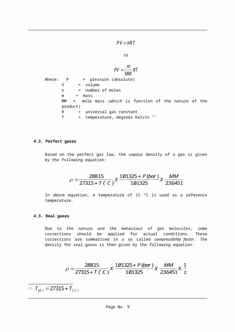
The density of a vapour depends on the following factors: Temperature, Pressure and nature of the product. The relation between these parameters is given by the perfect gas law:
PV nRT
or
PVm
MMRT
Where: P = pressure (absolute)V = volumen = number of molesm = mass MM = mole mass (which is function of the nature of the product)R = universal gas constantT = temperature, degrees Kelvin (°)
4.2. Perfect gases
Based on the perfect gas law, the vapour density of a gas is given by the following equation:
(°) T TK C( ) ( ). 27315
Page No. 5

28815
27315
101325
101325 236451
.
. ( )
. ( )
. .T CX
P barX
MM
In above equation, a temperature of 15 °C is used as a reference temperature.
4.3. Real gases
Due to the nature and the behaviour of gas molecules, some corrections should be applied for actual conditions. These corrections are summarised in a so called compressibility factor. The density for real gases is then given by the following equation:
28815
27315
101325
101325 236451
.
. ( )
. ( )
. .T CX
P barX
MMX
1
z
Compressibility factors are more important at higher temperatures and especially at high pressure (dense vapour condition). Under the conditions in a gas tanker or in a storage tank ashore, the compressibility factor is near to 1. The differences resulting by applying this compressibility factors are negligible.
Page No. 6

5. LIQUID DENSITY
5.1. Introduction
The density of a liquid as a function of temperature is usually given by a power series equation. For relative small temperature ranges, the density temperature relation ship can be regarded as linear. In the oil industry, the general practice is to correct observed measurements to volumes and/or densities to a reference temperature of 15 °C. Liquefied gases have a boiling point varying from 0°C for n-Butane to -162 °C for Methane (LNG). Temperature ranges are considerable greater when compared to the those found in the petroleum and chemical trades. This will reflect in other methods and quantity calculation routines for liquefied gases.
In the next paragraphs, methods are described for the density determination of commercial liquefied gases.
5.2. Practical density test method : The Pressure Hydrometer (ASTM D1657)
This test method, last revised in 1989, covers the determination of relative density or density of light hydrocarbons including Liquefied Petroleum gases (LPG). The test method is not applicable for products having vapour pressures higher than 1.4 MPa at 15 °C.
A pressure cylinder, constructed of glass or transparent plastic, is filled with liquid gas to a level at which an enclosed hydrometer floats freely (see figure 1). The hydrometer reading and the temperature of the sample are noted.
The obtained density must be corrected using ASTM Table 53B for correction of density to 15 °C or ASTM Table 23B for correction of relative density to 60/60F.
figure 5.1Pressure hydrometer cylinder
Page No. 7

5.3. Density from Compositional Analysis
5.3.1. ASTM D 2598
This practice covers, by compositional analysis, the determination of the relative density of Liquefied Petroleum Gases (Propane, Butane and their mixtures). The analytical composition of the liquid is obtained by gaschromatography. The composition of the mixture should be expressed in liquid volume percent. The theoretical calculation of the relative density is as follows:
Relative Density (60 / 60 F) =
Relative density (60 / 60 F) compound x C
100i i
i=1
n
Where :
Ci = Concentration of compound i, in liquid volume percent.
The relative density of different compounds are listed in Table 5.A (1) here below:
Table 5.A.
Relative density of compounds
Compound Relative Density at 60/60 °F (15.56 °C)
Ethane 0.35619
Propane 0.50699
Propylene 0.52095
n - Butane 0.58401
i- Butane 0.56287
(1) Ref : ASTM D 2598-91, 1996 Annual Book of ASTM standards, Volume 05.02
Page No. 8
5.3.2. The Francis Formula
The liquid density of mixtures of hydrocarbon liquids at their boiling point as a function of temperature as calculated by the Francis Formula is based on an extension of the correlation of the liquid density of pure hydrocarbon liquids, at their boiling point, as a function of the temperature. This correlation is achieved by neglecting the effect of volumetric shrinkage.
The Francis Formula is applicable only to LPG mixtures at their boiling point, within the temperature range -60°C to +30°C.
Appendix 2 gives the procedure for liquid density calculation of LPG by using the Francis Formula.
5.3.3. The COSTALD equation
The simplest and most obvious method for density determination of LPG mixtures is to assume that the mixtures are ideal. This implies that the density of the mixture is a weighted average of the molar volumes of the pure compounds. Method ASTM D 2598 as discussed in previous paragraph gives the calculated average density. However, it does not take into consideration the effect of mixing different molecules on the liquid density. Where LPG has been loaded or unloaded in or from a tank, the pressure in the tank will be in excess or below the saturated vapour pressure. The influence of this excess pressure on the liquid density is not incorporated in this method. A more complex method for calculating the liquid density is the Costald (Corresponding State of Liquid density ) method. This correlation is applicable for both the saturated and for the compressed liquid region.
A comparison between measured densities and densities computed using COSTALD indicates an average error of 0.08%. Errors greater than 0.2% occurred in mixtures containing higher concentrations of Ethane. The deviation tends to increase with increasing Ethane content.
Appendix 3 gives the formula and calculations which make up the Costald equation for saturated liquids.
5.3.4. Specific density calculation methods and tables
Specific calculation methods are introduced for the density calculation of single and pure compounds. These methods are frequently used due to they high accuracy.
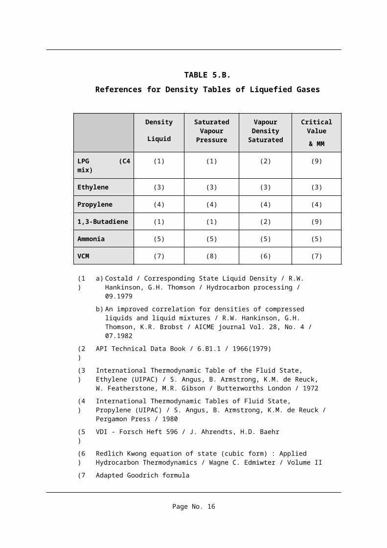
In Table 5.B below an overview is given of the most common used references on with the density tables are based for Liquefied gases such as Ethylene, Propylene, Butadiene, Vinyl Chloride Monomer, etc..
Page No. 9
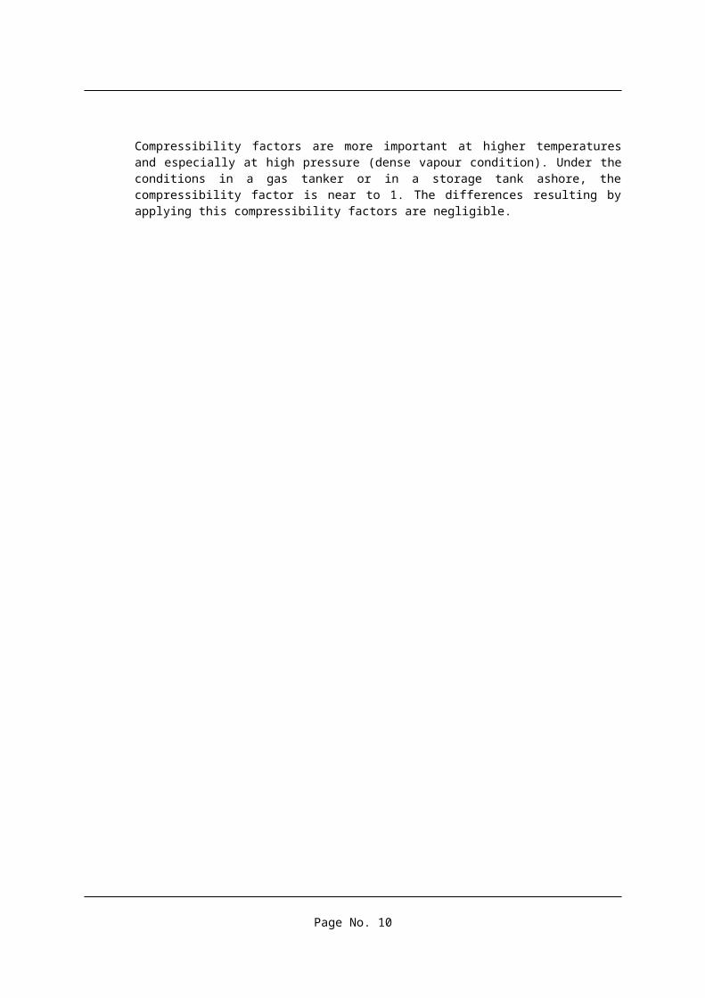
TABLE 5.B.
References for Density Tables of Liquefied Gases
Density
Liquid
Saturated Vapour
Pressure
Vapour Density
Saturated
Critical Value
& MM
LPG (C4 mix) (1) (1) (2) (9)
Ethylene (3) (3) (3) (3)
Propylene (4) (4) (4) (4)
1,3-Butadiene (1) (1) (2) (9)
Ammonia (5) (5) (5) (5)
VCM (7) (8) (6) (7)
(1) a) Costald / Corresponding State Liquid Density / R.W. Hankinson, G.H. Thomson / Hydrocarbon processing / 09.1979
b) An improved correlation for densities of compressed liquids and liquid mixtures / R.W. Hankinson, G.H. Thomson, K.R. Brobst / AICME journal Vol. 28, No. 4 / 07.1982
(2) API Technical Data Book / 6.B1.1 / 1966(1979)
(3) International Thermodynamic Table of the Fluid State, Ethylene (UIPAC) / S. Angus, B. Armstrong, K.M. de Reuck, W. Featherstone, M.R. Gibson / Butterworths London / 1972
(4) International Thermodynamic Tables of Fluid State, Propylene (UIPAC) / S. Angus, B. Armstrong, K.M. de Reuck / Pergamon Press / 1980
(5) VDI - Forsch Heft 596 / J. Ahrendts, H.D. Baehr
(6) Redlich Kwong equation of state (cubic form) : Applied Hydrocarbon Thermodynamics / Wagne C. Edmiwter / Volume II
(7) Adapted Goodrich formula
(8) Thermodynamic properties of vinyl Chloride monomer / British Chemical Engineering / Vol. 3 - 1958
(9) Engineering Data Book / Gas Processors Suppliers Association (GPA), Section 16 : 1970 with exemption of PC for LPG (C4 mix) where its value has been calculated by means of reference (1) b
Page No. 10

6. VOLUME AND TOTAL QUANTITY DETERMINATION
Commercial quantities (Bill of Lading) may be based on either static measurements made within the ship’s cargo tanks or shore tank measurements. Only a small percentage of quantities are based upon shore side flow metering, termed Dynamic Measurement. It is appropriate, therefore, to begin by presenting a procedure for the calculation of an inventory for a tank, whether it be in a ship or ashore.
The procedure to be presented first is not the most widely used technique but it provides a good example of the logical approach required.
A number of variations upon the basic procedure are possible, since there is no recognised single standard for the calculation. The method discussed in this section conforms to such standards as are in existence.
The determination of a tank inventory is the first stage in calculating a cargo quantity and is based upon the measurements of liquid level, liquid density, liquid temperature, vapour space temperature and vapour space pressure. Depending on the type of vessel, various corrections are to be applied, such as corrections for trim, list, shrinkage, tape, etc...
Temperature is extremely important and a reliable figure needs to be found for both the average liquid and the average vapour temperature. This is most accurately achieved using a correctly calibrated multipoint platinum resistance thermometer. The readings of all liquid and all vapour temperatures should be averaged to determine the required values. In general liquid temperatures are found to be constant throughout the liquid depth. The vapour space may show a very significant variation between the temperature near the liquid surface and that near the top of the tank. The determination of a single vapour temperature which is representative of the whole space is difficult, particularly when the liquid level in the tank is very low.
6.1. TANK INVENTORY
From the tank measurements the steps in the determination of the tank inventory are as follows:
a) Read the temperature profile to calculate an average liquid temperature and an average vapour temperature.
The average liquid temperature is the arithmetic mean of all temperature points within the liquid and the average vapour temperature is the arithmetic mean of all points within the vapour so long as the tank is of constant cross section with depth. Where the cross section changes a volume weighted average temperature should be calculated.
b) Read the cargo tank pressure
c) Read the liquid level;
Commonly a float connected by a tape (wire) to a measurement device above the cargo tank is lowered to the liquid surface.
Page No. 11

d) Make the following corrections - from the cargo tank calibration tables - which are necessary:
d 1. Trim correction
The liquid level on the level gauge a cargo tank depends on the trim of the vessel. Depending on the location of the level gauge on the cargo tank, depending on the liquid level and depending on the draft of the vessel, a positive or a negative correction must be applied.
Figure 6.1 ‘even keel’
Figure 6.2 ‘trim by stern’
d 2. List correction
For a similar reason as for the trim correction, a correction for the list of the vessel should be applied
Figure 6.3 ‘list’
Page No. 12

d 3. Float correction
The float is of the level gauge is lowered to the liquid surface. A buoyancy correction for the float, depending on the density of the liquid must be applied.
d 4. Tape correction
This temperature correction must compensate for the change in the vertical position of the gauge relative to the tank floor, due to thermal effects on the tank wall and also for the contraction in the gauge wire. The correction due to the temperature is made against the certified standard gauge temperature. This correction is function of the liquid level in fact to the length of the tape exposed to the vapour phase) and the temperature of the vapour phase.
e) From the corrected liquid level calculate liquid volume using the cargo tank calibration tables;
f) Calculate the vapour volume as the total tank volume minus the liquid volume, again with due allowance for temperature;
The cargo tanks of a gastanker as well as the cargo measurement equipment is calibrated at ambient conditions. Due to thermal effects on the cargo tank steel during loading operations, the used material will be subject to a shrinkage. A shrinkage correction for both, liquid and vapour volume should be applied.
g) Calculate the liquid mass as the product of liquid volume and liquid density.(see section 6.3 here below)
h) Calculate the vapour density (see section 4) from the average vapour temperature and pressure;.
Page No. 13

i) Calculate vapour mass as the product of vapour volume and vapour density
The vapour phase density is based upon the ideal gas laws and is calculated at tank pressure and at average vapour temperature. The vapour mass is based upon the product of a volume and a density, both evaluated at the average temperature of the vapour phase.
j) Calculate total mass as the liquid mass plus the vapour mass.
(see section 6.2 and 6.3 here below)
Appendix 3 shows a sheet which can used for the calculation routine. Obviously, the NGC templates, containing the same information are to be used on board of our fleet.
6.2. THE LIQUID QUANTITY
The use of the liquid density is an extremely important step in the whole quantity calculation procedure since liquid density is so important to the overall inventory figure which is calculated. The most accurate means of deriving the density is by liquid sampling and use of a gas chromatography. Gaschromatography is a common used laboratory technique for the determination of the composition of liquid and gas mixtures. A gaschromatograph is essentially a long packed tube through which molecules of different type travel at different rates. An LPG mixture injected as a sample at one end of the tube will appear some short time later as individual components at the opposite end. The components are identified by the time needed to flow through the tube; the concentration of individual components can be measured by a proper calibration procedure.
Great care must be taken in both the sampling and in transferring the small sample necessary for injection into the chromatograph. In particular it must be ensured that the sample is representative of the cargo as a whole and that volatile components are not lost during sampling, the storage and the handling of the sample.
The liquid mass is a product of the liquid volume and the liquid density. There are two options to calculate the liquid quantity:
Converting the liquid volume at actual temperature to liquid volume at reference temperature (15 °C) by using ASTM Table 54 (old) (*) ; multiplying with the liquid density at reference temperature. This method is in principle the same as which is used for Crude oil quantity determination;
Liquid volume at actual temperature multiplying with the liquid density at actual temperature.
The Francis Formula as well as the Costald method give calculation methods to determine liquid densities of LPG mixtures and some other mixtures of chemical gases at their observed temperature. The references as mentioned in Table 5.B of section 5 of this paper give us calculation methods to obtain liquid densities at observed temperature for pure chemical gases.
(*) Ref : IP 200 Petroleum measurement tables
Page No. 14

The first method is diverted from crude oil quantity calculation methods. To maximise accuracy, the latest published ASTM Tables 53 and 54 are presented in separate tables: A-Tables, Generalised crude oils; B-Tables, Generalised products; C-Tables, Individual and special application; and D-Tables, Generalised lubricating oils. For low density products and products at low temperature, the old edition - 1952 of Tables 53 and Table 54 should continue to be used. Obviously this practice will give results which are less accurate compared to those resulting from the second option.
Appendix 4 shows numerical calculations for an LPG mixture using different calculation methods resulting in different liquid quantities.
6.3. SUMMARY
The different options to calculate both, the quantity of Liquid as well the quantity vapour phase in a tank are summarised here below:
6.3.1. From Liquid density at observed temperature
Liquid Density at
Actual Temperature
XLiquid
Volume at actual
Temperature
Vapour Density at Actual
TemperatureX
Vapour volume at
Actual Temperature
How?
Costald Francis
Formula Density Tables
(pure compounds)
How?
Molecular Weight Formula
Page No. 15
6.3.2. From liquid temperature at reference temperature
Liquid Density at Reference Temperature
(15 °C)
XLiquid Volume at Reference Temperature
(15 °C)
Vapour Density at Actual
TemperatureX
Vapour volume at
Actual Temperature
How?
Pressure Hydrometer
Calculated from Composition
ASTM D 2598
Costald
Francis Formula
Density Tables (pure Compounds)
How?
Molecular Weight Formula
Page No. 16

7. SHORE TERMINAL CONSIDERATIONS
7.1. COMPARISONS BETWEEN SHIP AND TERMINAL FIGURES
We have looked in some detail at the calculation of the ship's cargo based upon tank measurement within the ship. Similar calculation procedures ashore should be applied except for some correction factors typical for ship’s measurements and calculations. It is natural now to consider how well these two approaches may be expected to agree. It is useful to begin by discussing the shore side tanks and exactly what happens when a ship is loaded.
FIGURE 7.1 . LOADING TERMINAL GENERAL ARRANGEMENT
Page No. 17
warm vapour
recirculation
loading
Plant production

Figure 7.1 shows an arrangement of a terminal in which two tanks are used for the storage of refrigerated product. One tanks may be used to service the ship loading, whilst the other receives the material from the production plant. The loading line to the ship is usually cooled down before loading operations by the provision of a circulation line back to the tanks.
In order to maintain the pressure in each tank within close limits, a reliquefaction system is provided which is used to prevent higher pressures being reached. To prevent the possibility of a vacuum in the shore a warm vapour input is supplied to each tank to allow rapid generation of vapour and a rapid increase in pressure.
When a ship is being loaded a vapour return may be connected to allow vapour to flow from the ship back to the shore. This vapour return may be directed to the shore tank being discharged, although provision is also made to flare this vapour, should it be of unacceptable quality. Therefore in many cases the manifold valve on the vapour return line is kept closed and should be considered only as being a safety measurement in case of an emergency.
The figure shows that the reliquefaction system is a common system between tanks and vapour may, therefore, be interchanged between the tanks. When the product is being run from the production facility to one of the tanks the rise in liquid level will force out vapour into the reliquefaction common-header. A falling liquid level in the shore tank being discharged will need to be replaced by vapour from one or more of the various sources. Similar vapour movements are also possible during the discharge process.
Above illustrate that the vapour and liquid movements ashore or between shore and ship during the loading of a gastanker are quite complex and these depend very much upon the rate, the temperature and the nature of the product which is transferred. Provided the loading rate is such that the ship reliquefaction plant can cope with any vapour generated by pumping power and other heat input to the flowing liquid, it is possible to load without the need for a vapour return. Under these conditions of a relatively low loading rate the vapour movements around the system are minimised. In such a circumstances, comparison between ship and terminal figures may be more relevant.
In order to overcome some problems the use of an accurate flow metering system is the only possible solution. This requires the metering of the liquid to the ship and the metering of the vapour return in case this is used. .
The question of flowmeter types is discussed in section 7.2, but although metering is not available on many terminals it will overcome both the problems associated with ship vapour returns.
Ship / shore quantity comparison is relevant provided that :
Proper calibration of both ship’s and shore tanks are available; The shore tank(s) is (are) separated from other means, such as shore flare, production
units, truck- or railcar loading,… The liquid line system from the shore tank to the ship’s manifold is full before and after
loading; The temperature of the product (i.e. density) in the shore line should be the same as in the
shore tank, both before and after loading; No vapours to be released from the ship’s cargo tanks to the shore flare, except when an
accurate flow meter is available.
Page No. 18

7.2. FLOWMETERING
The use of flowmetering at terminals has the advantage of giving a measurement uncertainty which is independent of the total quantity of cargo transfer. This is unlike the situation with static measurement where the uncertainty with large cargoes is much less, in percentage terms than with small cargoes. The uncertainty of flowmetering is about the same as that of static measurement for large loads, with the no vapour return qualification.
The minimum requirement for flowmetering is the measurement of liquid to the ship, when no vapour return is used, or the metering of both liquid and vapour return quantities.
The most widely used liquid flowmeter for LPG cargo measurement is the turbine meter, which may be used for both refrigerated and ambient temperature product. This meter, because it contains rotating parts, shows small random variations in calibration and, therefore, must be installed with the provision for proving. For ambient temperature products this prover may be of the loop type in which an inflated sphere is moved between mechanical detectors. This type of prover cannot be used under refrigerated conditions because the sphere becomes inelastic at low temperatures. For refrigerated products a piston prover must be used, with a metal piston with low temperature seal materials replacing the sphere.
In order to correctly use the flowmeter the relationship between the K factor, defined as number of pulses per unit volume, and flow rate should be programmed into the flow computer servicing the meter. This calibration is continuously applied to the meter during cargo loading.
The vortex meter is starting to be used for some liquid loading lines. This meter may be thought of as an obstruction within the pipe which causes vortices to be generated on each side of the obstruction. The principle is exactly that which causes a flag to flap on a flag pole as it moves from side to side with the wind generated vortices.By counting the vortices the fluid flow rate may be determined quite accurately. The meter has two advantages over the turbine meter. Firstly, it contains no moving parts and therefore needs no prover; secondly, it is significantly cheaper. Although the use of this meter is still in its infancy it promises to be of great value in LPG service. Evidence exists that uncertainties as low as those of turbine meters on LPG can be achieved with vortex meters, that is of the order of 0.3% on volume.
The measurement of gas vapour should not be ignored. If the liquid is metered during ship loading, the vapour return – if used- must also be metered. Ultrasonic meters offer the best possibility here mainly because they can scope with the wide range of flow rates typically found in vapour return lines. The ultrasonic meter measures the time of flight of a sound signal passing diagonally across the pipe. The times both in the direction of and against the fluid flow are required in order to determine flow rate. This meter also requires no prover and gives no obstruction to the flow. These meters are often not calibrated since their performance can be determined from their installation – admittedly with a worse uncertainly than could be expected with liquid metering. However this does not have a major effect on the overall measurement uncertainty since the liquid mass is always much greater than the vapour mass.
Page No. 19

The Coriolis mass flow has the advantages of a high accuracy. The measurement principle is based on the controlled generation of Coriolis forces. These forces are always present in systems when both transitional (straight line) and rotational (revolving) movements occur simultaneously. This principle has been adapted so an oscillation replaces the rotational movements. Two parallel measuring pipes with fluid flowing through them, are made to oscillate in antiphase so they act like a tuning fork. When mass is flowing through, there is a phase shift between the inlet and the outlet. As the mass flow increases, the phase difference also increases. This phase shift is determined using electro-dynamic sensors at the inlet and outlet. The measurement principle operates independently of temperature, pressure viscosity, conductivity or flow profile.
8. FUTURE DEVELOPMENTS
Today manufacturers of flow meters are promoting the use of Coriolis (mass) meters for LPG or Chemical gases, either refrigerated or pressurised. These meters are particularly usefull where products are traded on a mass basis since a single measurement of mass should have a better uncertainty than the combination of volume and density. They also have the theoretical advantage that they can be calibrated on -say- water and used for any other product. Corriolis meters have a very stable long term performance which means that they can be calibrated on water in a flow laboratory and on site using a mobile prover. Subsequently they can be recalibrated on water to confirm that no unacceptable shift has taken place.
Most static measurement is carried out with float gauges. Uncertainties are dependent on application and on calibration of the level gauge itself and on the volume calibration of the tank. For larger parcels, i.e. ship’s loading, static measurement can match metering systems and have the advantage of simplicity.
It is very difficult to specify measurement uncertainties in a standard since they will very dependent on installation, calibration, operating procedures etc…
Accuracy of static measurement is dependent on the accuracy of the calibration of the volume of the cargo tank and on the accuracy of the calibration of the instrumentation (levels, temperature and pressure). Volume calibration of a cargo tank is performed upon new building of the vessel or after some structural cargo tank modifications. Besides some custom requirements for the verification and certification of the accuracy of the instrumentation of a gastanker, no international standard exist until today in this respect. Measurement uncertainties are found at every stage of product movements and it is a necessity to implement regular and rigorous procedures to reduce this uncertainty to a minimum. Obviously, the implementation of quality standards such as ISO, ISM,… require well maintained and well calibrated equipment
Page No. 20

9. CONCLUSIONS
The quantity calculation of liquefied gases differs from those of other products due to the nature of the product. A reasonable amount of product exist as vapour. The only proper way to calculated the vapour quantity is by using the molecular weight formula. The molecular weight formula reflect the condition (temperature and pressure) as well as the nature (molecular mass) of the vapour.
Liquefied gases are handled in closed spaces from which air is totally excluded. The use of a density in air is irrelevant and should be considered as a theoretical approach. Therefore cargo quantities should be expressed as a mass (vacuo), rather than in weight (air).
The latest editions of the ASTM Table 53B and Table 54B are not applicable for gas calculations. When using ASTM tables, reference should be made to the old ASTM Table 53 and 54 which are obviously less accurate.
The Costald method provides in a density calculation method for LPG’s and mixture of chemical gases at their actual liquid temperature. Volume corrections to a standard temperature of 15 °C are not necessary.
Empirical formulas are available for the density calculation of many pure chemical gases such as Ethylene, Propylene, Ammonia Anhydrous,… They provide in a good correlation between the liquid temperature and the liquid density for particular products.
The layout of many of the terminals for loading liquefied gases make that ship’s quantity figures are the most reliable. A proper calibration of ship’s cargo tanks as well as their measurement systems (level, temperature and pressure) is necessary. They implementation of international calibration standards in this context is desirable.
Page No. 21


