Embed Size (px)
Citation preview

NGAO TT and TTFA Wavefront SensorPreliminary Design
KECK ADAPTIVE OPTICS NOTE 730
Version 1.1
May 19, 2010
J. Kent Wallace, Randall Bartos, and Gautam Vasisht, JPL

Table of Contents
1. Introduction...............................................................................................32. Requirements............................................................................................33. Overview....................................................................................................34. TT and TTFA fore-optics............................................................................35. TT WFS Optical Design.............................................................................36. TTFA WFS Optical Design.........................................................................37. Truth WFS Optical Design.........................................................................38. Opto-mech design......................................................................................39. Cryostat Design.........................................................................................310. Electronics Design..................................................................................311. Status......................................................................................................3

1. Introduction1.1Scope
This document describes the preliminary design of the low-order tip/tilt and tip/tilt/focus/astigmatism sensors for Keck’s Next Generation Adaptive Optics (NGAO) system. Version 1 of this document concentrates the optical and mechanical preliminary design, and the design of the cryostat for the IR detector. It does not cover design of the object selection mechanisms, the details of the IR detector technology, reliability, or prototyping.
1.2Significant Design Changes
We have detailed the optical design from the pick-off optics of the object selection mechanisms to the final focal plane. We have included rudimentary mounting for the 32x32 DM from Boston Micro Machines. Given that much of this design revolves around packaging, and most of the packaging revolves around the cryostat design, we have taken steps to detail this critical element as much as possible.
1.3Reference Document
2. Requirements2.1System Level Requirements2.2Functional Performance Requirements: Key ones
FR1531 Tip/tilt performance: 10 mas, on the skyPlate Scale: 50 mas Zenith Angle: 30 degree at full performance, 70 degree at
reduced performanceWavelength Range: J + H band
LOWFS Design Requirements FPR173 Static Calibration Errors: 25 nm, rms FR159 Patrol Range: 120 arc sec diameterFR175 Optical Transmission:
J-band (1.25um): 56% (TT) / 52% (TTFA)H-band (1.65um): 57% (TT) / 52% (TTFA)And after one year from first lockJ-band (1.25um): 47% (TT) / 48% (TTFA)H-band (1.65um): 43% (TT) / 43% (TTFA)
FR2024 Patrol Arm FOV: 5 arc sec (diameter) FR-172 Pupil Distortion: <5% of actuator pitch

FR162 Outer Field Radius: 60 arc sec
FR2604 Required Translation Range: +/- 1.25 mmFR2157, FR2169 DM Pupil Size: 9.3 mm
DM/P&S WFS Registration: Cold Room Temperature: -20 C
2.3Configuration Requirements 2.4Mass and Power
3. OverviewOur approach when starting the design of the low-order wavefront
sensor (LOWFS) was to first take full advantage of all the design work that had been done on the object selection mechanisms for the group working on the laser guide star (LGS) wavefront sensor. We recognized that there were several advantages to this approach. Not only would it save valuable design time but having common elements also makes the test and integration easier. Now, this means that we assume that the OSM’s for the LGS completely satisfy their requirement both in the positioning of the theta/phi arms but also in the requirements for the tip/tilt mechanism that is an integral part of the OSM assembly. If this is the case, then the only modification we make to this design is in the re-collimation optic in the pick-off arm, in order to make it work well over the LOWFS wavelength range.

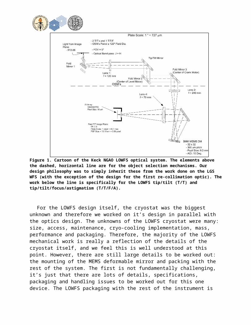
Figure 1. Cartoon of the Keck NGAO LOWFS optical system. The elements above the dashed, horizontal line are for the object selection mechanisms. Our design philosophy was to simply inherit these from the work done on the LGS WFS (with the exception of the design for the first re-collimation optic). The work below the line is specifically for the LOWFS tip/tilt (T/T) and tip/tilt/focus/astigmatism (T/T/F/A).
For the LOWFS design itself, the cryostat was the biggest unknown and therefore we worked on it’s design in parallel with the optics design. The unknowns of the LOWFS cryostat were many: size, access, maintenance, cryo-cooling implementation, mass, performance and packaging. Therefore, the majority of the LOWFS mechanical work is really a reflection of the details of the cryostat itself, and we feel this is well understood at this point. However, there are still large details to be worked out: the mounting of the MEMS deformable mirror and packing with the rest of the system. The first is not fundamentally challenging, it’s just that there are lots of details, specifications, packaging and handling issues to be worked out for this one device. The LOWFS packaging with the rest of the instrument is under a state of constant flux. It is our goal to nail the interface of the LOWFS to the second stage relay as soon as possible.
A cartoon showing the significant components of the LOWFS relay are shown in Fig. 1. We cartoon captures the major functional elements of the design.
4. TT and TTFA fore-optics4.1Object Selection Mechanisms
The object selection mechanisms we take whole-sale from the effort already devoted to their design for the LGS system. We assume that the vetting of these mechanisms is sufficient to allow them to be completely adopted by the LOWFS cameras. Not only does this save significant design work up front, but it also will save significant work in the hardware integration and test phase. So we accept these items as they have been designed, including the tip/tilt mirror mechanism. The only element that is changed in our design is the re-collimation optic. It has been designed for broadband operation in the near IR. A diagram of the object selection mechanism is shown below in Figure 2. A description of this design is given in the following paragraphs.
The selection mechanism is composed of rotation stages with an offset between them. At the center of each stage is a mirror, and the two mirrors together then form a periscope. This is known as a theta-phi pickoff arrangement. The ‘upper’ rotation stage, the one closest to the pick-off mirror is known as the lever motor and the ‘bottom’ stage is known as the crank motor.
The crank arm and the lever arms are balanced about their axis of rotation to prevent torque on the motor at any position of the arm. The crank and lever motors use PI’s M037 and M-038 drives. All M-037 rotation stages are equipped with ultra-precise worm gear drives allowing unlimited rotation in either direction. Model M- 037.DG is a closed-loop DC motor with shaft-mounted position encoders and precision gearheads providing 3.5 μrad at a design resolution of 0.6 μrad. Model M-038.DG1 is equipped with a closed-loop DC motor with shaft-mounted position encoder and precision gearhead providing minimum incremental motion of 3.5 μrad at a design resolution of 0.6 μrad.
The tip/tilt mirror is momentum compensated mirror from Left-hand design. It is mounted in the mechanical system that is attached to the lever motor, and contains the pick-off arm.
A Honeywell 8LS125 micro-switch and a custom contour milled track serve the purpose of a fail-safe system to prevent collision of the pick-off arms with its surrounding in case of software failure.

Figure 2. The object selection mechanism. This mechanism is inherited from the design work done for the LGS WFS. It is a theta-phi design implemented with two rotation stages, one off-set with respect to the other. The upper stage is the lever, the lower stage is the crank. A contact encoder and custom limit switch track are
used to prevent mechanical interference in case of software failures.
4.2Design of re-collimation Optic
This element serves two purposes. It re-collimates the beams that are picked-off in the LOWFS image plane. The beam is collimated so that the beam size is well maintained as it snake through the opto-mechanics of the object selection mechanisms. In collimating the beam, it also forms an image of the system pupil at the tip/tilt mechanism.
This optic is an air spaced achromat. The surfaces are spherical, the glasses, Fused Silica and Magnesium Fluoride, are readily available in high quality. Their properties are well understood. There is nothing particularly challenging about this element with regards to fabrication.
We first show an image of the object selection mechanism relay, then we show an image of the lens itself. Finally, the imaging performance is shown.

Figure 3. The object selection mechanism optical beam path. The first element in the system is a fold mirror. The three arms of the OSM are staggered in the focal plane to avoid mechanical interference. The re-collimation optic is subsequent to this initial fold. It is an air-spaced achromat that works over J/H bands. The next
optics in the beam path are: 1) the tip/tilt mirror, 2) the mirror at the center of the lever stage and 3) the mirror at the center of the crank stage.
Figure 4. The object selection mechanism re-collimation optic. The input is shown on the left, and the location of the re-image pupil is shown on the right. The field-
of-view of this system is five arc seconds in diameter, on the sky.
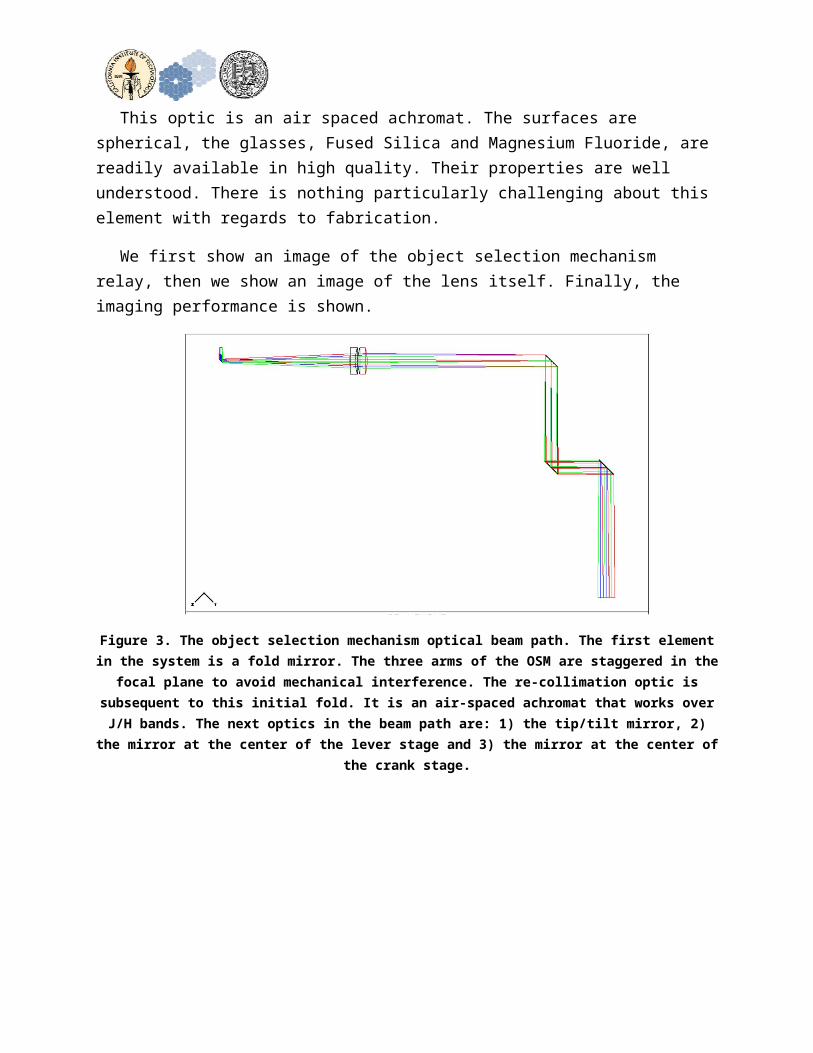
Figure 5. This spot diagram shows the optical performance of the OSM –recollimation optic over the +/- 2.5 arcsec (on the sky) radius FOV over the required bandpass. This system is diffraction limited over this field of view.
5. TT WFS Optical DesignAfter the optics for the object selection mechanism, we come to the
optical relay for the tip/tilt sensor. There are two lenses, and these optics serve the role of: 1) relaying the system pupil to the deformable mirror and 2) relaying the intermediate focus to the final image plane at the correct plate scale. So, we’ll describe each of these elements in the next sections.
5.1TT Pupil Plane Imaging
This optic reimages the pupil that is at the tip/tilt mirror to the 32x32 deformable mirror. This optic also forms an intermediate focus. The focal length of this lens is about 120 mm. The imaging is roughly 1:1. Again this lens is made from Fused Silica and Magnesium Fluoride elements with spherical surfaces.

Figure 6. The optical layout of the LOWFS T/T system with last surface of the pupil imaging lens highlighted in red. This optic re-images the pupil at the tip/tilt
mirror to the BMM 32x32 DM located at the bottom of the image. This optic also forms an intermediate focus between the lens and the DM.
Figure 7. An unfolded image of the pupil imaging lens. The focal length of the lens is about 120 mm, and the pupil imaging is therefore a 2f imaging system with a
unit magnification.
5.2TT Focal Plane Imaging

The remaining powered optical element in this beam path is the relay lens. This element does nothing more than relay the intermediate focus formed by the pupil imaging lens to the detector image plane with a slight change in magnification to establish the correct plate scale. The lens is again made of Fused Silica and Magnesium Fluoride, like the other lenses. Surfaces are spherical.
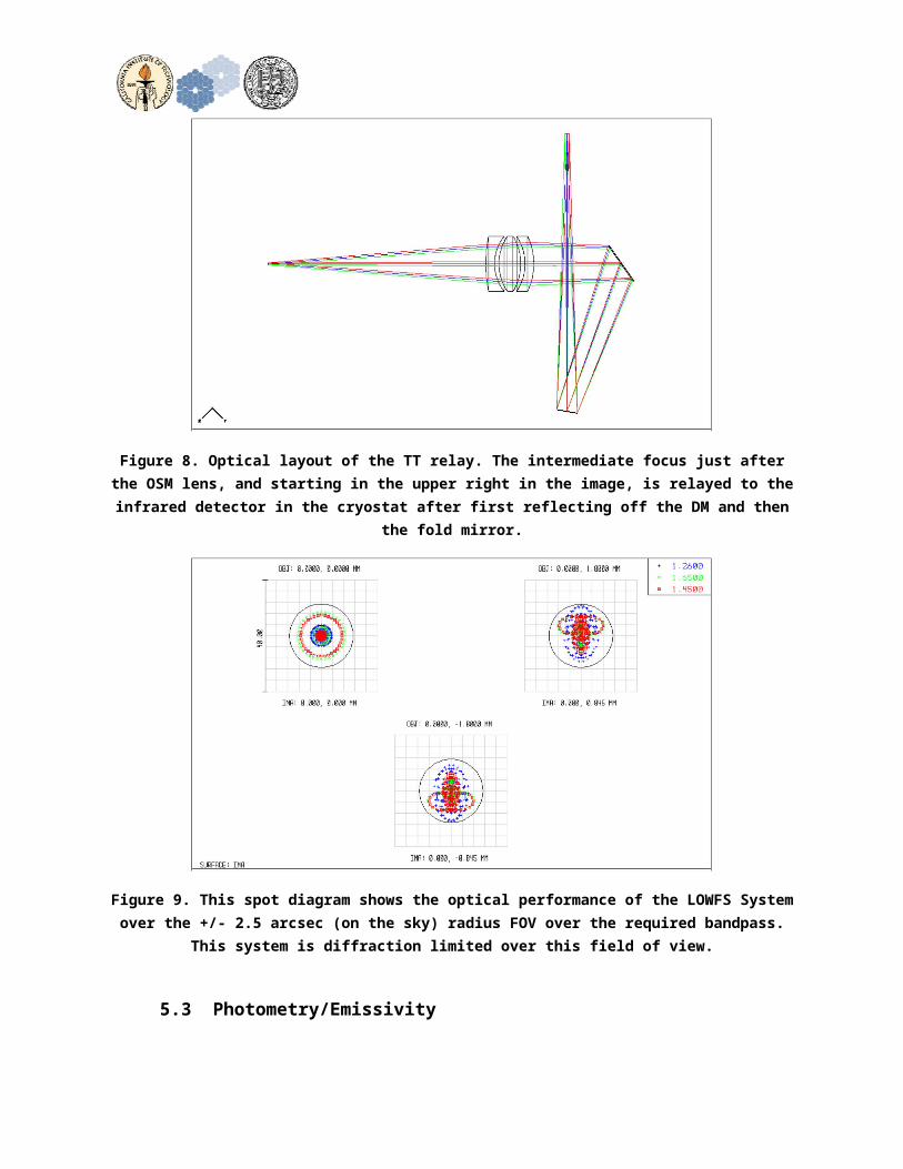
Figure 8. Optical layout of the TT relay. The intermediate focus just after the OSM lens, and starting in the upper right in the image, is relayed to the infrared
detector in the cryostat after first reflecting off the DM and then the fold mirror.
Figure 9. This spot diagram shows the optical performance of the LOWFS System over the +/- 2.5 arcsec (on the sky) radius FOV over the required bandpass. This
system is diffraction limited over this field of view.

5.3Photometry/Emissivity
6. TTFA WFS Optical DesignThe optical design for the TTFA arm of the LOWFS inherits all of the optics previously described for the TT assemblies. Where the TT assemblies end, we add two additional optics. The first optic is a re-collimation that creates a real image of the pupil, and the second optic is a lenslet array that is placed in this pupil plane to form the 2x2 Shack-Hartman spots on the final detector.
Figure 10. Complete optical path of the TTFA arm of the LOWFS. The optics are completely common to the TT assembly with the exception of the last two
elements: 1) the re-collimation achromat and 2) the lenslet array.
6.1Recollimation Lens and Lenslet
The TTFA re-collimation lens and the lenslet are show below in Figure 11. The optical layout shows the beam path from the intermediate focus before the DM to the fold mirror, relay lens, and then the re-collimation optic and the lenslet. The recollimation lens has a focal length of about 40 mm and creates a real image of the pupil about 30 mm after the last surface of the lens assembly. The lens itself is very similar to the other lenses in the system: the two glasses are Fused Silica and Magnesium Fluoride, and all the surfaces are spherical. It is an air spaced achromat.
The lenslet is shown as a paraxial lens at the moment. A custom lenslet is likely in order for this element. As shown, the sub-aperture are about 3.2 mm square in a 6.4 mm diameter pupil. The focal length is 20 mm and this then gives a plate scale of roughly 50 mas per pixel on the final image plane. The four spots are separated from each other by roughly 180 pixels in the x and y direction on the array.
Figure 11. A closer view of the last section of the optical beam path. This optical layout starts at the intermediate focal plane of the pupil imaging lens, and the
ends at the focal plane of the detector. The re-collimation optic is about 10 mm in diameter and has a focal length of about 40 mm. The real pupil is formed about 30
mm after the last surface. The lenslet array divides this pupil into 2x2 sub-apertures.
6.2Photometry/Emmisivity
7. Truth WFS Optical DesignThe truth wavefront sensor is a low order Shack-Hartman wavefront sensor, working in the visible portion of the spectrum (500 – 1000 nm). The beam path is picked off with a dichroic in the collimated space immediately after the object selection mechanisms, and before the DM in the TTFA relay.
Once picked off from the IR beam, the optical relay for the TWFS comes in two portions: 1) the pupil relay lens to the lenslet and 2) the relay of the lenslet spots detector via a field lens and focusing lens. The optical layout of this configuration is shown below in Figure 12.

Figure 12. Optical layout of the Truth WFS from the object selection mechanism, the pick-off dichroic, and the truth WFS relay. The TWFS relay consists first of a
collimator/lenslet and second of a relay that images the spots to the visible detector.
7.1TWFS Optical Relay
The Truth WFS is shown below in figure 13. The optical layout shows the beam from the pick-off dichroic, the re-collimation lens and lenslet array. The recollimation lens has a focal length of 50 mm and creates a real image of the pupil about 3.6 mm in diameter. The recollimation lens itself is an off-the-shelf contacted achromatic doublet.
The lenslet is shown immediately after the re-collimation lens. The sub-apertures are 0.732 mm square and there are five sub-apertures across the pupil. The focal length is 12.3 mm and this then gives a plate scale of roughly 177 um per arcsecond on the final image plane.

Figure 13. Detailed layout of the Truth WFS. The re-collimation lens and the lenslet are the first two elements. After the lenslet spots is an optical relay
composed of a field lens and focusing element. The detector window and focal plane are shown on the right.
Figure 14. A image of the intermerdiate focal spots after the lenslet array.

Figure 15. Image quality of the Truth wavefront sensor spots in the final focal plane. These spots are diffraction limited over the full wavelength range.
7.2Photometry/Emmisivity
8. Opto-mech designThe opto-mechanics for the LOWFS is shown below in figure 16. We have
placed all the key elements on a single translation stage that will accommodate any changes in the LOWFS focal plane position. The stage also contains the object selection mechanisms on the entrance to the optical system. This design is compact to aid in packaging and ensure instrument stability. All the rest of the elements will be mounted with off-the-shelf components. The only exception is the deformable mirror which will need some significant design time. The cryostat will also be supported directly off of the translation stage.

Figure 16. The packaging for the LOWFS TT arm. All opto-mech components will be supported on a single translation stage. The mounts for the pupil imaging lens,
fold mirror and relay mirror can be handily accomplished with off-the-shelf components. The mounting of the DM will require careful thought and some
custom design.
8.1OSM Lens mount
This custom doublet, like all the custom elements, will be delivered in a custom lens cell. This cell will then be mounted into the pick-off arm of the object selection mechanism. Given this modular approach, we foresee no difficulties as long as the interface between the two components are well defined.
8.2Relay Lens Mount
The relay lens, also a custom lens in its own cell, will be mounted in an off-the-shelf directly to the interface plate to the translation stage. This stage will have x, y, and z translational degrees of freedom to aid in the alignment.
8.3DM Mounting

The mounting of the 32x32 BMM DM will require significant design work. It needs to not only provide stable mounting of the DM itself, but also accommodate the multitude of cables as well. There is the possibility that the face sheet will also need to be evacuated to keep the humidity low. Currently, we have simply adopted the same mounting method as used by the DM in the second-stage relay. This placeholder does a fair job of capturing the size of the final DM mount.
8.4Cryostat Lens mounts
The cryostat lens will be mounted directly to the cryostat itself. The custom triplet will have its own lens cell. We envision a threaded lens tube attached directly to the cryostat front face. The threading will allow fine adjustment of the custom lens in the longitudinal direction relative to the focal plane.
8.5Translation Stage
All these mechanics will be mounted to flexure stage with a total travel range of 3 mm. A linear roller bearing stage is not being used because the lubricant is squeezed out from between the rollers and the raceway when using the stage over such a short travel range. It is not desirable to re-lubricate the bearing surfaces by running a roller bearing stage over an extended travel range because the pickoff arms of the three different stages could potentially interfere with each other if the stages did not travel together. Limiting the travel to 3 mm total travel prevents this interference problem. Each stage will be actuated by a linear actuator capable of maintaining a linear position resolution at the micron level.
9. Cryostat DesignOur design efforts began with the cryostat, given that the design of this
system drives many of the other design considerations, we wanted to address its design first. The cryostat is relatively compact, fundamentally simple in design and construction, with no internal mechanisms. We want to treat is as closely as possible to a simple IR imaging device, with no unnecessary complication. The opto-mechanics for the LOWFS is shown below in Figure 17.

``
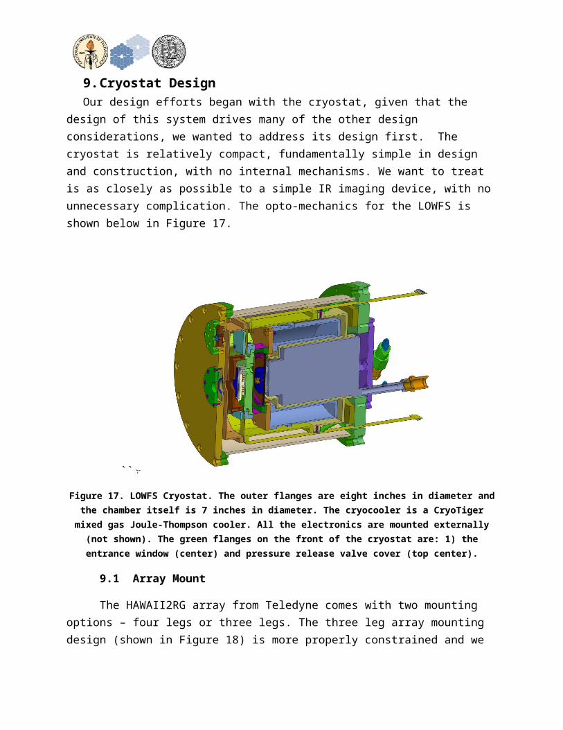
Figure 17. LOWFS Cryostat. The outer flanges are eight inches in diameter and the chamber itself is 7 inches in diameter. The cryocooler is a CryoTiger mixed gas Joule-Thompson cooler. All the electronics are mounted externally (not shown).
The green flanges on the front of the cryostat are: 1) the entrance window (center) and pressure release valve cover (top center).
9.1Array Mount
The HAWAII2RG array from Teledyne comes with two mounting options – four legs or three legs. The three leg array mounting design (shown in Figure 18) is more properly constrained and we choose this method. This array mount is then mated to the detector cold plate via three linear flexures. This flexure design minimizes the transmission of mechanical stress to the array mounting frame. The details of these flexures is shown below in Figure 19.

Figure 18. Mechnics for the array mounting. The three legged option (shown above) allows for a more kinematic and mechanically stable form of mounting.
The flex cable coming from the array and leading to a Hirose connector contains all the electrical signals to and from the array.
Figure 19. The mounting of the array legs to the cryostat is via three linear blade flexures (shown as the green circular disk above). This method of mounting
minimizes the transmission of unbalanced forces through the legs to the array.
9.2Cryo-cooler choice
We have selected the CryoTiger for our means of cryo-cooling. The CryoTiger is very simple to operate, provides sufficient steady-state cooling power for our small cryostat (shown in Figure 20 below). The cooler also imparts very little vibration as compared to other cryocooling options as shown in Figure 21 below. The lines for the compressed gas can be quite long, and empirical evidence is that the cooling becomes more efficient the longer the lines get. The vendor will guarantee performance for lengths up to 250 ft, but compressor lines much longer have been used by other observatories, with no significant impact to performance. Therefore, the compressor can be quite distant from the cryostats. They can also be mounted separately to aid in the isolation of the mechanical noise from the compressors.
Figure 20. Compressor and cold head for the Cryo-Tiger mixed-gas Joule-Thomson cooler. The mixed gas lines can be quite long.

Figure 21. Cooling capacity for different models of cryocoolers. We plan on using the Standard PT-14. This has several Watts of margin at 90K.
Figure 22. Power spectrum of the vibrations for the CryoTiger in comparison to other cryocooling options. The blue line is the cryotiger, its level of vibration is several orders of magnitude lower than other options because of its very simple
operation.
9.3Getters
An ion pump shall be used to remove residual gas molecules inside the cryostat after initial pump down and gas molecules that permeate the O-ring seals of the cryostat. The vacuum ports of the three cryostats can be connected to a single ion pump using a vacuum manifold. Ion pumps can provide a service life up to 80000 hours (9 years). An ion pump has no moving parts and will hold vacuum in the event of a power failure.
Mounting locations and containers for traditional charcoal and zeolite getter materials are also planned to be included in the cryostat design. The inclusion of removable getter containers will permit the cryostat to operate in the absence of an ion pump if desired when the getter materials are installed. The charcoal getter shall be mounted such that it can be maintained at the cold temperature.
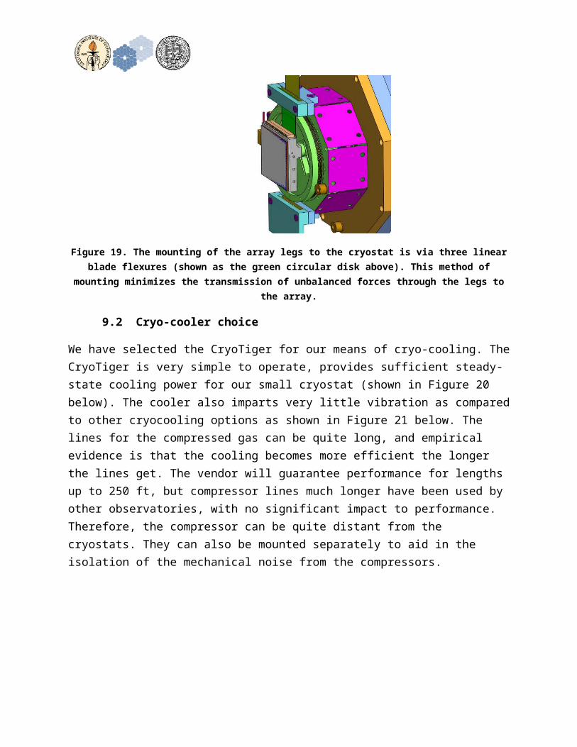
Figure 23. Ion pump to maintain high vacuum thermal insulation over time.
9.4Heaters/Thermisters
The mounting base of the detector array shall have the temperature controlled through the use of a heater. The heater shall be a 50 ohm length of nichrome heater wire wrapped and around the detector mounting base. The wire shall be potted with thermally conductive epoxy to provide a good thermal connection to the mounting base.

9.5Vacuum Port
An NW-16 flange is planned to provide compact vacuum port for the cryostat. The vacuum flange is placed in the back flange of the cryostate between the outer disk of the cryotiger and the outer bolt pattern of the rear cryostat flange as shown below in Figure 24. A small vacuum valve can be used to isolate each individual cryostat from vacuum manifold connected to the ion pump and main vacuum pump port. This permits the removal of individual cryostats from the vacuum manifold while leaving the other cryostats connected.
The NW16 flange tube will also have the capability of accepting a vacuum plug to provide a compact vacuum valve if desired. The operation of the vacuum valve is as follows. A special adaptor is mated to the end of the vacuum valve. This adaptor has, in a ‘T’ configuration both the threaded tool to remove the plug under vaccum, and the lines that lead to the vacuum pump. When the ‘T’ joint and vacuum lines are evacuated, the threaded tool that is integral to the joint is used mated to the plug and the plug pulled back until the cryostat has an open pathway to the vacuum line. The cryostat is then pumped down. When pressure reaches an acceptable level, the plug is re-installed, the insertion tool is un-threaded and removed, and the vacuum line can then be detached. The advantage of this design is that the vacuum hardware is greatly reduced in size.

Figure 24. The compact vacuum valve is shown as the yellow colored plug in the left side of the back flange. The plug is shown in the light blue internal to the NW-
16 flange tube.
Figure 25. A small vacuum valve used to isolate each cryostat from the vacuum manifold.
9.6Thermal Loading Calculations
We have performed the thermal loading calculates to help us determine the required cooling capacity of the cryocooler and it’s steady state operational temperature. This mode is composed of two key components: the thermal conduction model and the radiation model.

Figure 26. The thermal conduction model for the LOWFS Cryostat.
Figure 27. Resistive model for the LOWFS cryostat.
A preliminary thermal analysis was performed on the LOWFS cryostat. The cryostat is required to maintain the LOWFS detector array at a temperature of ~90 degrees Kelvin or less. The objectives of the analysis were as follows:

• Preliminary steady–state thermal analysis showing the temperature distribution at the end of a cool down cycle.
• Preliminary cool down analysis incorporating the cooler capacity as a function of temperature.
The model should be adequately detailed to give the cool down time with a maximum error of 50% A lumped parameter thermal model was used to perform the thermal analysis of the LOWFS dewar. The differential equations of the thermal model were solved numerically using MATLAB to produce a cool down simulation of the LOWFS dewar. The steady state performance of the dewar was obtained by looking at the final values of the cool down simulation after the dewar components had reached their steady state temperature. The LOWFS dewar cool down simulation assumed that 5 watts of cooling power was available. The thermal analyses assumed that the detector was off and not dissipating heat until the detector reached its final operating temperature below 80 degrees Kelvin. The LOWFS dewar simulation model took approximately 11 hours to reach a steady state temperature below 80 degrees Kelvin. The LOWFS dewar radiation shields reached their steady state temperature after approximately 40 hours. Once the 80 degree Kelvin detector temperature was achieved, it took the dewar simulation model approximately 1 watt of cooling power to maintain the LOWFS dewar component temperatures at their steady state values in a 293 degree Kelvin ambient environment assuming a maximum detector heat load of 0.25 watts.
10. Electronics Design10.1 Array Read out electronics
The array is a HAWAII2RG. It is the best low-noise, near IR detector available. Although a full science grade array is quite expensive, our current plan is to procure a full science grade array. Such an array will guarantee that the pixels we need for the LOWFS sensor are the ones we get. We only require a small number of pixels in order to make the tip/tilt measurement. We read out the array with a set of Leach Electronics that includes boards for clocks, biases and a video card. These electronics interface to the computer via a communications card.

Figure 28. Electronics diagram for the LOWFS sensor. All electronics for the array are external to the cryostat. The flex cable from the array is extended through the
back cover to interface boards external to the cryostat. These interface face boards then lead to the Leach readout electronics (the clocks biases card and the video card). House keeping signals (heaters, thermistors) come from a different flex
cable.
We are also considering the use of the Sidecar ASIC from Teledyne as another possible means of reading out the array. The Sidecar has the distinct advantage of providing digital values very early in the detector signal path. This is done by using a dedicated readout ASIC that is located close to the detector internal to the cryostat. With this board so close to the array, the detector signal is much less susceptible to noise pick-up. The changing noise pattern from imaging arrays between the lab and telescope environments is typical problem with these types of instruments. The trade is therefore between the time and effort devoted for more detailed design that both supports the ASIC and its software interface issues, versus the gain of not debugging spurious noise sources that are different between the lab and observatory. A functional block diagram of the HAWAII implemented with an ASIC is shown below.

Figure 29. Block diagram of detector readout with the Teledyne Sidecar ASIC. The USB Driver, which from Teledyne is strictly MS Windows based, requires some subtleties in implementation (a virtual windows machine embedded in a non-
Windows system). The detector/ASIC combination, however, is immune to spurious noise pick-up which is a distinct advantage when it comes to integration at the
observatory.
10.2 Array Heaters10.3 Temperature Sensors
For the temperature sensors, we will use standard platinum sensors. The physical package for these sensors is small and they have good thermal sensitivity around 80 degrees K
Figure 30. Platinum temperature sensor for the LOWFS Cryostat.
10.4 Array Thermal Control
To control detector head temperature and to provide monitoring of temperatures at various points inside the dewar, we will use a Lake Shore Cryotronics, Inc. Model 340 temperature controller as this is the

standard temperature controller used at the KECK telescope. The detector array temperature is controlled by heating the array to a stable temperature above the steady state temperature achieved by the cryo-cooler using the closed loop temperature controller. The Model 340 main control loop can provide a heater with DC electrical power up to 100 watts. Heater channel is a linear, low noise RFI filtered current source that can provide up to 2.0 Ampere into 50Ω or 25Ω resistive loads. The maximum heater current can be limited among 5 values ranging from 0.25 amps to 2 amps for the 100 watt control loop. The model 340 is able to shut down the control loop if an over temperature condition is detected. The cryostat will also include a thermal fuse as a backup to shut down heater power in the event of an over temperature condition that could damage the detector.
Figure 31. The temperature monitor controller for the LOWFS cryostat.
10.5 Temperature Monitoring
The temperature of additional locations inside the cryostat will be monitored to permit operators to confirm the proper operation of the array thermal control system. The additional sensors will be monitored using a Lake Shore 3468 eight channel input option card. In addition to its high accuracy/performance and low noise design, unique features include: Internal Data Logging, IEEE-488 connectivity, RS232 connectivity , and a large easy to read display and extensive utility software.

Figure 32. The temperature monitor controller for the LOWFS Cryostat.
11. Status11.1 Requirements Compliance11.2 Remaining Work to do