Embed Size (px)
Citation preview

1.47
PowerMaster® NFPA Pneumatic Cylinders Index
PowerMaster® NFPA Pneumatic Cylinders Index
Air to 200 psi, 1-1/2" thru 14" Bore Page
Features & Specifications……………………………………………………. 1.48-1.49Options and Modifications…………………………………………………… 1.50-1.52Oversize Ports, Rod Boots, Stroke Adjustment (Fold-out page*)………1.51a*Rod End Options & Standard Porting (Fold-out page*)………………… 1.52a*Preferred Standard Cylinders - 3 Day Delivery Program…………………1.53-1.54Mounting Style Index……………………………………………………………1.55Mounting Styles & Dimensional Data ………………………………………1.56-1.69 D Double Rod Cylinder………………………………………………………1.56-1.57 ME3 Head Square Flange……………………………………………………1.56-1.57 ME4 Cap Square Flange……………………………………………………1.56-1.57 MF1 Head Rectangular Flange……………………………………………1.58-1.59 MF2 Cap Rectangular Flange………………………………………………1.58-1.59 MF5 Head Square Flange……………………………………………………1.58-1.59 MF6 Cap Square Flange……………………………………………………1.58-1.59 MP1 Cap Fixed Clevis………………………………………………………1.60-1.61 MP3 Cap Fixed Eye………………………………………………………… 1.60-1.61 MP2 Cap Detachable Clevis……………………………………………… 1.60-1.61 MP4 Cap Detachable Eye……………………………………………………1.60-1.61 MU3 Universal Clevis……………………………………………………… 1.60-1.61 MS1 Side End Angle…………………………………………………………1.62-1.63 MS7 Side End Lugs…………………………………………………………1.62-1.63 MS2 Side Lugs……………………………………………………………… 1.64-1.65 MS3 Centerline Lugs…………………………………………………………1.64-1.65 MS4 Side Tapped……………………………………………...…………… 1.64-1.65 MX0 No Mountings………………………………………………………… 1.64-1.65 MT1 Head Trunnion…………………………………………………………1.66-1.67 MT2 Cap Trunnion………………………………………………….…………1.66-1.67 MT4 Intermediate Fixed Trunnion…………………………………………1.66-1.67 MX1 Tie Rods Extended Both Ends………………………………………1.68-1.69 MX2 Tie Rods Extended Cap End Only………………………………… 1.68-1.69 MX3 Tie Rods Extended Head End Only…………………………………1.68-1.69 MX4 Tie Rods Extended Two Each End…………………………………1.68-1.69Accessories (fold-out page*)………………………………………………… 1.69a-1.70a*How To Order…. …………………………………………………………………1.70Rod Protective Cover…………………………...………………………………1.71Service Information…. …………………………………………………………1.72-1.73Capacity Chart Per Inch of Stroke……………………………………………1.74Force for Push and Pull Stroke……………………………………………… 1.75Mounting Considerations for Cylinders…………………………………… 1.76Stop Tube and Column Strength Considerations…………………………1.77-1.78Oversize Rod Selection……………...…………………………………………1.79Cylinder Specification Sheet (for faxing)……………...……………………1.80-1.81
Court
esy
of CM
A/F
lodyn
e/H
ydra
dyn
e ▪
Motion C
ontr
ol ▪
Hyd
raulic
▪ P
neu
mat
ic ▪
Ele
ctrica
l ▪
Mec
han
ical
▪ (
800)
426-5
480 ▪
ww
w.c
maf
h.c
om

Powermaster® PP Pneumatic
1.48
Weight information - see Cylinder Options section.
Court
esy
of CM
A/F
lodyn
e/H
ydra
dyn
e ▪
Motion C
ontr
ol ▪
Hyd
raulic
▪ P
neu
mat
ic ▪
Ele
ctrica
l ▪
Mec
han
ical
▪ (
800)
426-5
480 ▪
ww
w.c
maf
h.c
om

Powermaster® PP Pneumatic
1.49
Court
esy
of CM
A/F
lodyn
e/H
ydra
dyn
e ▪
Motion C
ontr
ol ▪
Hyd
raulic
▪ P
neu
mat
ic ▪
Ele
ctrica
l ▪
Mec
han
ical
▪ (
800)
426-5
480 ▪
ww
w.c
maf
h.c
om

Powermaster® PP Pneumatic
1.50
1.78
Court
esy
of CM
A/F
lodyn
e/H
ydra
dyn
e ▪
Motion C
ontr
ol ▪
Hyd
raulic
▪ P
neu
mat
ic ▪
Ele
ctrica
l ▪
Mec
han
ical
▪ (
800)
426-5
480 ▪
ww
w.c
maf
h.c
om

Powermaster® PP Pneumatic
1.51
Court
esy
of CM
A/F
lodyn
e/H
ydra
dyn
e ▪
Motion C
ontr
ol ▪
Hyd
raulic
▪ P
neu
mat
ic ▪
Ele
ctrica
l ▪
Mec
han
ical
▪ (
800)
426-5
480 ▪
ww
w.c
maf
h.c
om

Powermaster® PP Pneumatic
1.51a
Court
esy
of CM
A/F
lodyn
e/H
ydra
dyn
e ▪
Motion C
ontr
ol ▪
Hyd
raulic
▪ P
neu
mat
ic ▪
Ele
ctrica
l ▪
Mec
han
ical
▪ (
800)
426-5
480 ▪
ww
w.c
maf
h.c
om

Powermaster® PP Pneumatic
1.52a
1.52
MM B AE NARod A +0.000 C D AC AD +0.000 AF KK1 KK2 +0.002Dia. -0.003 -0.005 -0.0020.625 0.750 1.124 0.38 0.50 1.12 0.62 0.250 0.375 7/16-20 1/2-20 0.5631.000 1.125 1.499 0.50 0.88 1.62 0.94 0.375 0.688 3/4-16 7/8-14 0.9381.375 1.625 1.999 0.62 1.12 1.75 1.06 0.375 0.875 1-14 1 1/4-12 1.3131.750 2.000 2.374 0.75 1.50 2.00 1.31 0.500 1.125 1 1/4-12 1 1/2-12 1.6882.000 2.250 2.624 0.88 1.69 2.62 1.69 0.625 1.380 1 1/2-12 1 3/4-12 1.9402.500 3.000 3.124 1.00 2.06 3.25 1.94 0.750 1.750 1 7/8-12 2 1/4-12 2.4383.000 3.500 3.749 1.00 2.62 3.62 2.44 0.875 2.250 2 1/4-12 2 3/4-12 2.9383.500 3.500 4.249 1.00 3.00 4.38 2.69 1.000 2.500 2 1/2-12 3-12 3.4384.000 4.000 4.749 1.00 3.38 4.50 2.69 1.000 3.000 3-12 3 1/2-12 3.9384.500 4.500 5.249 1.00 SH 1 5.25 3.19 1.500 3.500 3 1/4-12 4 1/4-12 4.4385.000 5.000 5.749 1.00 SH 1 5.38 3.19 1.500 3.875 3 1/2-12 4 3/4-12 4.9385.500 5.500 6.246 1.00 SH 1 6.25 3.94 1.875 4.375 4-12 5 1/4-12 5.4387.000 7.000 7.749 1.00 SH 2 5 1/2-12 6-12 6.9388.000 8.000 8.749 1.00 SH 2 5 3/4-12 7 1/2-12 7.938
10.000 10.000 10.749 1.00 SH 2 7 1/4-12 9 1/2-12 9.875Spanner Wrench Holes: SH 1 = 0.56" dia., SH 2 = 0.66" dia.
PISTON ROD END
Court
esy
of CM
A/F
lodyn
e/H
ydra
dyn
e ▪
Motion C
ontr
ol ▪
Hyd
raulic
▪ P
neu
mat
ic ▪
Ele
ctrica
l ▪
Mec
han
ical
▪ (
800)
426-5
480 ▪
ww
w.c
maf
h.c
om

Powermaster® PP Pneumatic
1.52
Court
esy
of CM
A/F
lodyn
e/H
ydra
dyn
e ▪
Motion C
ontr
ol ▪
Hyd
raulic
▪ P
neu
mat
ic ▪
Ele
ctrica
l ▪
Mec
han
ical
▪ (
800)
426-5
480 ▪
ww
w.c
maf
h.c
om

1.53
Powermaster® PP Pneumatic Preferred Standard Cylinders Program-3 Day Delivery Guarantee
Bosch Rexroth NFPA Cylinders “Preferred Standard” Cylinders
3 Day Delivery Guarantee*
Powermaster® Pneumatic Cylinders (PP) (250 psi) Bore: 1 ½”, 2”, 2 ½”, 3 ¼”, 4”, 5”, 6”, 8”. Strokes to: 99—7/8” Rod Diameters: 5/8” thru 2” (standard, 1st & 2nd oversize) Mounts: 1 ½” – 8”: MX0,1, 2, 3, 4; MP1; MS2; MT1; MT2 and MT4.
1 ½” – 6”: MF1, MF2, MF5, MF6, MP2, MS1, MS4 & MU3. ME3 & ME4 for 8” only. MT4.
Standard rod ends – KK1, KK2 male, KK1 Female, studded, safe. Port or Cushion locations: Quadrants 1, 2, 3, 4 (except MT1 and MT2 which are at 1 or 3). Either Buna N or Viton seals. Quantities up to 5 pieces for a given model. Expanded cylinder options on 3 day cylinders: Special Rod Thread Lengths (“A” dimension) Extended Rods (“W” dimensions) Piston set screwed to rod *Preferred Standard Cylinders ship within three days or Bosch Rexroth pays the freight. Other Delivery Programs 5 Day Options: BSPP or Metric Port Threads Blunt Rod End Stop Tube MT4 Mounts with specified “XI” dimensions Black Epoxy Paint Check with factory for deliveries: Stainless steel rod material Metallic Rod Wipers Cylinder must be able to be configured on BRP online configurator to be delivered within this program. Check for Deliveries on other mounts, options, bore sizes, longer strokes, etc.!
10 Day Options: Double Rod Cylinders in MF1, MS2 & MS4 mountings Proximity Switches in Head and/or Cap
Court
esy
of CM
A/F
lodyn
e/H
ydra
dyn
e ▪
Motion C
ontr
ol ▪
Hyd
raulic
▪ P
neu
mat
ic ▪
Ele
ctrica
l ▪
Mec
han
ical
▪ (
800)
426-5
480 ▪
ww
w.c
maf
h.c
om

1.54
Powermaster® PP Pneumatic Preferred Standard Cylinders Program-3 Day Delivery Guarantee
Bosch RexrothAvailable Mountings – Preferred Standard Cylinders
Fixed Clevis MP1 DetachableClevis MP2
UniversalClevis MU3
Head TrunnionMT1
Rear (Cap)Trunnion MT2
IntermediateFixed TrunnionMT4 (Centeredonly)
Side Lugs MS2 Side TappedMS4
Tie Rod MountMX0,1,2,3, & 4
HeadRectangularFlange MF1
CapRectangularFlange MF2
Head SquareFlange MF5
Cap SquareFlange MF6
Head & CapSquare FlangeME3 & ME4
Side EndAngles MS1
See page 1.53 for Preferred Standard Cylinders program rules.
Court
esy
of CM
A/F
lodyn
e/H
ydra
dyn
e ▪
Motion C
ontr
ol ▪
Hyd
raulic
▪ P
neu
mat
ic ▪
Ele
ctrica
l ▪
Mec
han
ical
▪ (
800)
426-5
480 ▪
ww
w.c
maf
h.c
om

Powermaster® PP Pneumatic
1.55
page 1.56 page 1.56
page 1.56
page 1.58
page 1.58 page 1.58 page 1.58
page 1.60
page 1.60
page 1.60
page 1.60
page 1.60
page 1.62
page 1.62
page 1.64 page 1.64 page 1.64
page 1.66 page 1.66
page 1.66 page 1.68
Court
esy
of CM
A/F
lodyn
e/H
ydra
dyn
e ▪
Motion C
ontr
ol ▪
Hyd
raulic
▪ P
neu
mat
ic ▪
Ele
ctrica
l ▪
Mec
han
ical
▪ (
800)
426-5
480 ▪
ww
w.c
maf
h.c
om

Powermaster® PP Pneumatic
1.56
Court
esy
of CM
A/F
lodyn
e/H
ydra
dyn
e ▪
Motion C
ontr
ol ▪
Hyd
raulic
▪ P
neu
mat
ic ▪
Ele
ctrica
l ▪
Mec
han
ical
▪ (
800)
426-5
480 ▪
ww
w.c
maf
h.c
om

Powermaster® PP Pneumatic
1.57
1.52a.
1.70.
Court
esy
of CM
A/F
lodyn
e/H
ydra
dyn
e ▪
Motion C
ontr
ol ▪
Hyd
raulic
▪ P
neu
mat
ic ▪
Ele
ctrica
l ▪
Mec
han
ical
▪ (
800)
426-5
480 ▪
ww
w.c
maf
h.c
om

Powermaster® PP Pneumatic
1.58
Court
esy
of CM
A/F
lodyn
e/H
ydra
dyn
e ▪
Motion C
ontr
ol ▪
Hyd
raulic
▪ P
neu
mat
ic ▪
Ele
ctrica
l ▪
Mec
han
ical
▪ (
800)
426-5
480 ▪
ww
w.c
maf
h.c
om

Powermaster® PP Pneumatic
1.59
1.52a
1.56.
Court
esy
of CM
A/F
lodyn
e/H
ydra
dyn
e ▪
Motion C
ontr
ol ▪
Hyd
raulic
▪ P
neu
mat
ic ▪
Ele
ctrica
l ▪
Mec
han
ical
▪ (
800)
426-5
480 ▪
ww
w.c
maf
h.c
om
Powermaster® PP Pneumatic
1.60
Court
esy
of CM
A/F
lodyn
e/H
ydra
dyn
e ▪
Motion C
ontr
ol ▪
Hyd
raulic
▪ P
neu
mat
ic ▪
Ele
ctrica
l ▪
Mec
han
ical
▪ (
800)
426-5
480 ▪
ww
w.c
maf
h.c
om

Powermaster® PP Pneumatic
1.61
1.52a.
Court
esy
of CM
A/F
lodyn
e/H
ydra
dyn
e ▪
Motion C
ontr
ol ▪
Hyd
raulic
▪ P
neu
mat
ic ▪
Ele
ctrica
l ▪
Mec
han
ical
▪ (
800)
426-5
480 ▪
ww
w.c
maf
h.c
om

Powermaster® PP Pneumatic
1.62
Court
esy
of CM
A/F
lodyn
e/H
ydra
dyn
e ▪
Motion C
ontr
ol ▪
Hyd
raulic
▪ P
neu
mat
ic ▪
Ele
ctrica
l ▪
Mec
han
ical
▪ (
800)
426-5
480 ▪
ww
w.c
maf
h.c
om

Powermaster® PP Pneumatic
1.63
1.52a.
Court
esy
of CM
A/F
lodyn
e/H
ydra
dyn
e ▪
Motion C
ontr
ol ▪
Hyd
raulic
▪ P
neu
mat
ic ▪
Ele
ctrica
l ▪
Mec
han
ical
▪ (
800)
426-5
480 ▪
ww
w.c
maf
h.c
om

Powermaster® PP Pneumatic
1.64
Court
esy
of CM
A/F
lodyn
e/H
ydra
dyn
e ▪
Motion C
ontr
ol ▪
Hyd
raulic
▪ P
neu
mat
ic ▪
Ele
ctrica
l ▪
Mec
han
ical
▪ (
800)
426-5
480 ▪
ww
w.c
maf
h.c
om

Powermaster® PP Pneumatic
1.65
1.52a.
Court
esy
of CM
A/F
lodyn
e/H
ydra
dyn
e ▪
Motion C
ontr
ol ▪
Hyd
raulic
▪ P
neu
mat
ic ▪
Ele
ctrica
l ▪
Mec
han
ical
▪ (
800)
426-5
480 ▪
ww
w.c
maf
h.c
om

Powermaster® PP Pneumatic
1.66
Court
esy
of CM
A/F
lodyn
e/H
ydra
dyn
e ▪
Motion C
ontr
ol ▪
Hyd
raulic
▪ P
neu
mat
ic ▪
Ele
ctrica
l ▪
Mec
han
ical
▪ (
800)
426-5
480 ▪
ww
w.c
maf
h.c
om

Powermaster® PP Pneumatic
1.67
1.52a.
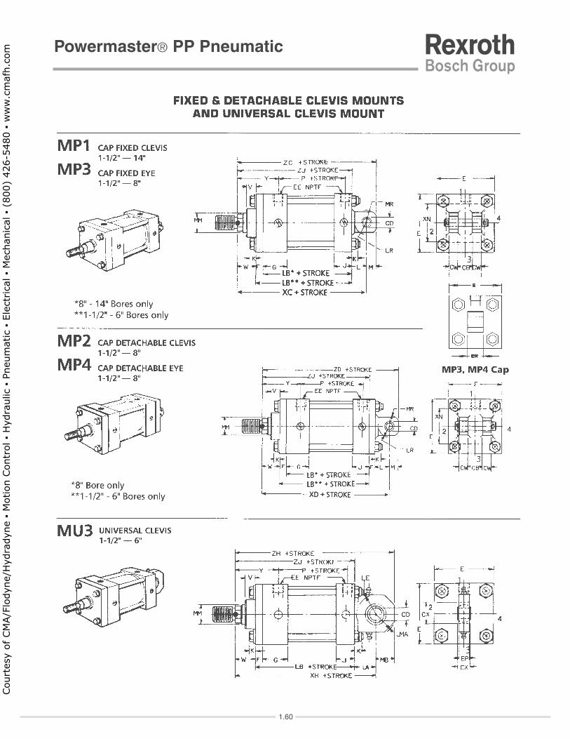
*TDBore E F G J K P BD EE LB +0.000 TL TM UB UM UTSize NPTF -0.0021.50" 2.00 0.38 1.50 1.00 0.22 2.25 1.25 0.38 4.00 1.000 1.00 2.50 2.25 4.50 4.002.00" 2.50 0.38 1.50 1.00 0.27 2.25 1.50 0.38 4.00 1.000 1.00 3.00 2.75 5.00 4.502.50" 3.00 0.38 1.50 1.00 0.27 2.38 1.50 0.38 4.13 1.000 1.00 3.50 3.25 5.50 5.003.25" 3.75 0.63 1.75 1.25 0.34 2.63 2.00 0.50 4.88 1.000 1.00 4.50 4.25 6.50 5.754.00" 4.50 0.63 1.75 1.25 0.34 2.63 2.00 0.50 4.88 1.000 1.00 5.25 5.00 7.25 6.50
6.25 8.25 Air PP
6.75 8.75 Oil PH
6.00" 6.50 0.75 2.00 1.50 0.44 3.13 2.50 0.75 5.75 1.375 1.38 7.63 7.38 10.38 9.25
8.00" 8.50 0.75 2.00 1.50 0.56 3.25 2.50 0.75 5.13 1.375 1.38 9.75 9.50 12.50 11.25
10.00" 10.63 0.75 2.25 2.00 0.66 4.13 3.00 1.00 6.38 1.750 1.75 12.00 11.75 15.50 14.13
12.00" 12.75 0.75 2.25 2.00 0.66 4.63 3.00 1.00 6.88 1.750 1.75 14.00 13.75 17.50 16.25
14.00" 14.75 0.75 2.75 2.25 0.78 5.50 3.50 1.25 8.13 2.000 2.00 16.25 16.00 20.25 18.75
*TD tolerance - bolt-on pins: +0.001"/-0.003"
5.00" 2.001.251.750.635.50 5.130.50 2.880.44 7.506.001.00 1.00
Court
esy
of CM
A/F
lodyn
e/H
ydra
dyn
e ▪
Motion C
ontr
ol ▪
Hyd
raulic
▪ P
neu
mat
ic ▪
Ele
ctrica
l ▪
Mec
han
ical
▪ (
800)
426-5
480 ▪
ww
w.c
maf
h.c
om

Powermaster® PP Pneumatic
1.68
Court
esy
of CM
A/F
lodyn
e/H
ydra
dyn
e ▪
Motion C
ontr
ol ▪
Hyd
raulic
▪ P
neu
mat
ic ▪
Ele
ctrica
l ▪
Mec
han
ical
▪ (
800)
426-5
480 ▪
ww
w.c
maf
h.c
om

Powermaster® PP Pneumatic
1.69
1.52a.
Court
esy
of CM
A/F
lodyn
e/H
ydra
dyn
e ▪
Motion C
ontr
ol ▪
Hyd
raulic
▪ P
neu
mat
ic ▪
Ele
ctrica
l ▪
Mec
han
ical
▪ (
800)
426-5
480 ▪
ww
w.c
maf
h.c
om

Powermaster® PP Pneumatic
1.69a
Court
esy
of CM
A/F
lodyn
e/H
ydra
dyn
e ▪
Motion C
ontr
ol ▪
Hyd
raulic
▪ P
neu
mat
ic ▪
Ele
ctrica
l ▪
Mec
han
ical
▪ (
800)
426-5
480 ▪
ww
w.c
maf
h.c
om

1.70a
5.625
Powermaster® PP Pneumatic
Court
esy
of CM
A/F
lodyn
e/H
ydra
dyn
e ▪
Motion C
ontr
ol ▪
Hyd
raulic
▪ P
neu
mat
ic ▪
Ele
ctrica
l ▪
Mec
han
ical
▪ (
800)
426-5
480 ▪
ww
w.c
maf
h.c
om

Powermaster® PP Pneumatic
1.70
Court
esy
of CM
A/F
lodyn
e/H
ydra
dyn
e ▪
Motion C
ontr
ol ▪
Hyd
raulic
▪ P
neu
mat
ic ▪
Ele
ctrica
l ▪
Mec
han
ical
▪ (
800)
426-5
480 ▪
ww
w.c
maf
h.c
om

Powermaster® PP Pneumatic
1.71
Court
esy
of CM
A/F
lodyn
e/H
ydra
dyn
e ▪
Motion C
ontr
ol ▪
Hyd
raulic
▪ P
neu
mat
ic ▪
Ele
ctrica
l ▪
Mec
han
ical
▪ (
800)
426-5
480 ▪
ww
w.c
maf
h.c
om

Powermaster® PP Pneumatic
1.72
Court
esy
of CM
A/F
lodyn
e/H
ydra
dyn
e ▪
Motion C
ontr
ol ▪
Hyd
raulic
▪ P
neu
mat
ic ▪
Ele
ctrica
l ▪
Mec
han
ical
▪ (
800)
426-5
480 ▪
ww
w.c
maf
h.c
om

Powermaster® PP Pneumatic
1.73
Includes Ref. Items 9a, 9c, 9d & 9e.
REPAIR KITSRepair parts included in the following repair kits are available only in kit form. Kits should be ordered by kit part numbers plus cylinder part
number when possible. Some kits may have an excess of parts not used in some cylinder models. Discard these parts or keep for later use.
Other parts not included in repair kits must be ordered separately by reference number, description, and cylinder part number.
Head Cushion SealBuna N With Buna N With
Urethane Rod Viton Urethane Rod Buna N*Rod Wiper (std.) Wiper (std.)
Diameter Part Number Part Number Part Number Part Number0.63" R433023506 R433023936 R433014982 R432029151
1.00" R433023510 R433014756 R433014984 R433023150
1.38" R433014766 R433023946 R433014986 R433015396
1.75" R433023515 R433023952 R433014988 R433022387
2.00" R433023519 R433023958 R433014990 R433022388
2.50" R433023523 R433023964 R433024068 R433023465
3.00" R433023526 R433014768 R433024071
3.50" R433014844 R433074988 R433074775
4.00" R433014682 R433021263 R433014976
4.50" R433014684 R433014978
5.00" R433014686 R433024267 R433014980
5.50" R433014688* Buna N rubber (ref.11).
For high-temp. operation,
consult the factory.
Bore BUNA N VITONSize Part Number Part Number Part Bore Sizes1.50" R433023971 R433023977 R433015593 Number2.00" R433023981 R433023987 R433015593 R433015236 1.5", 2", 2.5" Buna-N
2.50" R433023993 R433023997 R433015593 R433016568 3.25", 4", 5" Buna-N
3.25" R433024002 R433024009 R433015594 R433023258 6" thru 14" Buna-N
4.00" R433024012 R433024018 R433015594 R433072609 1.5", 2", 2.5" Viton
5.00" R433024022 R433024027 R433015594 R433074773 3.25", 4", 5" Viton
6.00" R433024031 R433024037 R433015595 R433023256 6" thru 14" Viton
8.00" R433024041 R433024043 R433015595 Includes Ref. items 8a & 8b
10.00" R433024045 R433024047 R433015302
12.00" R433024049 R433024051 R433015302
14.00" R433024053 R433024055 R433015596 5cc tube R431001589
* Buna N rubber (Ref. 19) 5 oz. tube R431001590For high-temperatureoperation,consult factory.
Includes Ref. Items 9a, 9c, 9d & 9e.
Cylinder Lube Grease
Cushion Needle ValveAssemblies (Exact-a-just™)
Piston & Tube Seal Kit Cap Cushion SealBUNA N*
Part Number
R433024261
R433024269
Includes Ref. items: 5a, 5b, 5c, 5d, 5e & 5f
Rod Seal Kit (less Rod Bearing)
Includes Ref. items 5b, 5c, 5d, 5e & 5f
Viton
Part Number
R433023951
R433023957
R433023963
R433023969
Rod Cartridge Kit (with Rod Bearing)
R433023935
R433023941
R433023945
Court
esy
of CM
A/F
lodyn
e/H
ydra
dyn
e ▪
Motion C
ontr
ol ▪
Hyd
raulic
▪ P
neu
mat
ic ▪
Ele
ctrica
l ▪
Mec
han
ical
▪ (
800)
426-5
480 ▪
ww
w.c
maf
h.c
om

Powermaster® PP PneumaticApplication Data
1.74
Court
esy
of CM
A/F
lodyn
e/H
ydra
dyn
e ▪
Motion C
ontr
ol ▪
Hyd
raulic
▪ P
neu
mat
ic ▪
Ele
ctrica
l ▪
Mec
han
ical
▪ (
800)
426-5
480 ▪
ww
w.c
maf
h.c
om

Powermaster® PP PneumaticApplication Data
1.75
Court
esy
of CM
A/F
lodyn
e/H
ydra
dyn
e ▪
Motion C
ontr
ol ▪
Hyd
raulic
▪ P
neu
mat
ic ▪
Ele
ctrica
l ▪
Mec
han
ical
▪ (
800)
426-5
480 ▪
ww
w.c
maf
h.c
om

Powermaster® PP PneumaticApplication Data
1.76
Court
esy
of CM
A/F
lodyn
e/H
ydra
dyn
e ▪
Motion C
ontr
ol ▪
Hyd
raulic
▪ P
neu
mat
ic ▪
Ele
ctrica
l ▪
Mec
han
ical
▪ (
800)
426-5
480 ▪
ww
w.c
maf
h.c
om

Powermaster® PP PneumaticApplication Data
1.77
(see page 1.78)
(see page 1.79)
Court
esy
of CM
A/F
lodyn
e/H
ydra
dyn
e ▪
Motion C
ontr
ol ▪
Hyd
raulic
▪ P
neu
mat
ic ▪
Ele
ctrica
l ▪
Mec
han
ical
▪ (
800)
426-5
480 ▪
ww
w.c
maf
h.c
om

Powermaster® PP PneumaticApplication Data
1.78
1.79.
Court
esy
of CM
A/F
lodyn
e/H
ydra
dyn
e ▪
Motion C
ontr
ol ▪
Hyd
raulic
▪ P
neu
mat
ic ▪
Ele
ctrica
l ▪
Mec
han
ical
▪ (
800)
426-5
480 ▪
ww
w.c
maf
h.c
om

Powermaster® PP PneumaticApplication Data
1.79
1.78.
1.75.
Court
esy
of CM
A/F
lodyn
e/H
ydra
dyn
e ▪
Motion C
ontr
ol ▪
Hyd
raulic
▪ P
neu
mat
ic ▪
Ele
ctrica
l ▪
Mec
han
ical
▪ (
800)
426-5
480 ▪
ww
w.c
maf
h.c
om

Bosch Rexroth Corporation, Pneumatics 1953 Mercer Road, Lexington, KY 40511-1021 Tel: 859-254-8031 / Fax: 859-254-4188 or 800-489-4188 Email: [email protected] Web: www.boschrexroth-us.com
CYLINDER SPECIFICATION SHEET
Customer: Cylinder Location / Machine:
1. QUANTITY _______________________ PRICING
2. BASIC CYL. MODEL: HH PP PH TM
BORE DIA.: 1-1/2 2 2-1/2 3-1/4 4 5 6 7 8 10 12-14
ROD DIA.: 5/8, 1, 1-3/8, 1-3/4, 2, 2-1/2, 3, 3-1/2, 4, 4-1/2, 5, 5-1/2, 7, 8-1/2
STD.MOUNTING: MP-1, MP-2, MP-3, MP-4, MU-3, MF-1, MF-2, MF-5, MF-6, ME-3,
ME-4, ME-5, ME-6, MS-1, MS-2, MS-3, MS-4, MS-7, MT-1, MT-2, MT-4,
X1= ____________, MX-0, MX-1, MX-2, MX-3, MX-4 TIE ROD BB = __________
ROD: Single Double
Special Mounting ______________________________________________________________________
3. STROKE * STROKE ______________ Inches @ ___________ Per inch
FOR STOP TUBES SPECIFY: Length:__________________ Effective Working Stroke ____________
Base Price _____________
* Plus __________________ Inches @ ____________ Per inch
4. ROD DETAILS Rod End Style: Male Female Threads _____________________________
SPECIAL ROD END MODIFICATIONS: Specify with NFPA dimensions __________________________
____________________________________________________________________________________
SPECIAL ROD MATERIAL ____________________ Base Price ___________________________
* Plus __________________ Inches @ ____________ Per inch
5. CUSHION Head End: YES NO Head End Adj. Location 1 2 3 4
Cap End: YES NO Cap End Adj. Location 1 2 3 4
SPECIAL CUSHION MODIFICATIONS: Specify Extended, Etc. ___________________
6. PORTS Std. Ports: YES NO Locations: Head End 1 2 3 4 Cap End 1 2 3 4
EXTRA or SPECIAL PORTS:
Head End: Qty ___________ Type ______________ Size _____________ Location 1 2 3 4
Cap End: Qty ___________ Type ______________ Size _____________ Location 1 2 3 4
7. BLEEDS Head End _________ Location 1 2 3 4 Cap End __________ Location 1 2 3 4
8. SEALS Standard Viton Cast-Iron Poly-Pak
Special __________________________________________________________________________
9. OPERATING Air ________________ Oil _______________ Water _____________ Other _______________
CONDITIONS Hydraulic Fluid ____________________________ Temperature _______________________________
Pressure (operating) _______________________ Pressure (max) ______________________________
Water Fitted ______________________________ Other _____________________________________
10. SPECIAL ____________________________________________________________________________________
FEATURES ____________________________________________________________________________________
Cylinder Part No. ___________________________ TOTAL LIST PRICE ________________________
PLEASE CIRCLE EACH ITEM & FILL IN THE APPROPRIATE BLANKS
ACCESSORIES REQUIRED (specify Part Number and Quantity
QTY PART NUMBER @ _______________
Rod Clevis
Pin
Female Rod Eye
Clevis Bracket
Eye Bracket
Other Accessory
TOTAL LIST PRICE CYLINDER & ACCESSORIES
* NOTE: Fraction of inch priced at next whole inch increment.
1.80
Court
esy
of CM
A/F
lodyn
e/H
ydra
dyn
e ▪
Motion C
ontr
ol ▪
Hyd
raulic
▪ P
neu
mat
ic ▪
Ele
ctrica
l ▪
Mec
han
ical
▪ (
800)
426-5
480 ▪
ww
w.c
maf
h.c
om

TYPES OF CYLINDER MOUNTS
Cylinders are ported at #1 and cushion adjustments are #2 unless specified differently.
Cylinder Specification Sheet (page 2 of 2)
1.81
Court
esy
of CM
A/F
lodyn
e/H
ydra
dyn
e ▪
Motion C
ontr
ol ▪
Hyd
raulic
▪ P
neu
mat
ic ▪
Ele
ctrica
l ▪
Mec
han
ical
▪ (
800)
426-5
480 ▪
ww
w.c
maf
h.c
om
NOTICES TO PRODUCT USERS1. WARNING: FLUID MEDIA Bosch Rexroth pneumatic devices are designed and tested for use
with filtered, clean, dry, chemical free air at pressures and
temperatures within the specified limits of the device. For use with
media other than air or for human life support systems, Bosch
Rexroth must be consulted. Hydraulic cylinders are designed for
operation with filtered, clean, petroleum based hydraulic fluid;
operation using fire-resistant or other special types of fluids may
require special packing and seals. Consult the factory.
2. WARNING: MATERIAL COMPATIBILITY Damage to product seals or other parts caused by the use of non-
compatible lubricants, oil additives or synthetic lubricants in the air
system compressor or line lubrication devices voids Bosch
Rexroth's warranty and can result in product failure or other
malfunction. See lubrication recommendations below.
AIR LINE LUBRICANTS! In service higher than 18 cycles per
minute or with continuous flow of air through the device, an air line
lubricator is recommended. * (Do not use line lubrication with
vacuum products.) However, the lubricator must be maintained
since the oil will wash out the grease, and lack of lubrication will
greatly shorten the life expectancy. The oils used in the lubricator
must be compatible with the elastomers in the device. The
elastomers are normally BUNA-N, NEOPRENE, VITON, SILICONE
and HYTREL. Bosch Rexroth recommends the use of only
petroleum-based oils without synthetic additives, and with an
aniline point between 180° and 210° F.
COMPRESSOR LUBRICANTS! All compressors (with the
exception of special "oil free" units) pass oil mist or vapor from the
internal crankcase lubricating system through to the compressed
air. Since even small amounts of non-compatible lubricants can
cause severe seal deterioration (which could result in component
and system failure) special care should be taken in selecting
compatible compressor lubricants. It is recommended that users
review the National Fluid Power Association "Recommended
Guide Lines For Use Of Synthetic Lubricants In Pneumatic Fluid
Power Systems" (NFPA T1-1978).
3. WARNING: INSTALLATION AND MOUNTING The user of these devices must conform to all applicable electrical,
mechanical, piping and other codes in the installation, operation or
repair of these devices.
INSTALLATION! Do not attempt to install, operate or repair these
devices without proper training in the technique of working on pneumatic
or hydraulic systems and devices, unless under trained supervision.
Compressed air and hydraulic systems contain high levels of stored
energy. Do not attempt to connect, disconnect or repair these products
when system is under pressure. Always exhaust or drain the pressure
from system before performing any service work. Failure to do so can
result in serious personal injury.
MOUNTING! Devices should be mounted and positioned in such
manner that they cannot be accidentally operated.
4. WARNING: APPLICATION AND USE OF PRODUCTS The possibility does exist for any device or accessory to fail to operate
properly through misuse, wear or malfunction. The user must consider
these possibilities and should provide appropriate safe guards in the
application or system design to prevent personal injury or property
damage in the event of malfunction.
5. WARNING: CONVERSION, MAINTENANCE AND REPAIR When a device is disassembled for conversion to a different
configuration, maintenance or repair, the device must be tested for
leakage and proper operation after being reassembled and prior to
installation.
MAINTENANCE AND REPAIR! Maintenance periods should be
scheduled in accordance with frequency of use and working conditions.
All Bosch Rexroth products should provide minimum of 1,000,000
cycles of maintenance free service when used and lubricated as
recommended. However, these products should be visually inspected
for defects and given an "in system" operating performance and leakage
test once a year. Where devices require major repair as result of the
one million cycles, one year, or routine inspection, the device must be
disassembled, cleaned, inspected, parts replaced as required, rebuilt
and tested for leakage and proper operation prior to installation. See
individual catalogs for specific cycle life estimates.
6. PRODUCT CHANGES Product changes including specifications, features, designs and
availability are subject to change at any time without notice. For critical
dimensions or specifications, contact factory.
*Many Bosch Rexroth pneumatic components can operate with or
without air line lubrication; see individual sales catalogs for details.
--Refer to the appropriate service catalog for parts and service information.
LIMITATIONS OF WARRANTIES & REMEDIESBosch Rexroth warrants its products sold by it to be free from defects in material and workmanship to the following: For twelve months after shipment Bosch Rexroth will repair or replace (F.O.B. our works), at its option, any equipment which under normal conditions of use and service proves to be defective in material or workmanship at no charge to the purchaser. No charge will be made for labor with respect to defects covered by this Warranty, provided that the work is done by Bosch Rexroth or any of its authorized service facilities.However, this Warranty does not cover expenses incurred in the removal and reinstallation of any product, nor any downtime incurred, whether or not proved defective. All repairs and replacement parts provided under this Warranty policy will assume the identity, for warranty purposes, of the part replaced, and the warranty on such replacement parts will expire when the warranty on the original part would have expired. Claims must be submitted within thirty days of the failure or be subject to rejection. This Warranty is not transferable beyond the first using purchaser. Specifically, excluded from this Warranty are failures caused by misuse, neglect, abuse, improper operation or filtration, extreme temperatures, or unauthorized service or parts. This Warranty also excludes the use of lubricants, fluids or air line additives that are not compatible with seals or diaphragms used in the products. This Warranty sets out the purchaser's exclusive remedies with respect to products covered by it, whether for negligence or otherwise. Neither, Bosch Rexroth nor any of its affiliates will be liable for consequential or incidental damages or other losses or expenses incurred by reason of the use or sale of such products.Our liability (except as to title) arising out of the sale, use or operation of any product or parts, whether on warranty, contract or negligence (including claims for consequential or incidental damage) shall not in any event exceed the cost of replacing the defective products and, upon expiration of the warranted period as herein provided, all such liability is terminated. THIS WARRANTY IS IN LIEU OF ALL OTHERWARRANTIES, EXPRESS OR IMPLIED, WHETHER FOR MERCHANTABILITY OR FITNESS FOR A PARTICULAR PURPOSE OR OTHERWISE. No attempt to alter, amend or extend this Warranty shall be effective unless authorized in writing by an officer of Bosch Rexroth Corporation. Bosch Rexroth reserves the right to discontinue manufacture of any product, or change product materials, design or specifications without notice. C
ourt
esy
of CM
A/F
lodyn
e/H
ydra
dyn
e ▪
Motion C
ontr
ol ▪
Hyd
raulic
▪ P
neu
mat
ic ▪
Ele
ctrica
l ▪
Mec
han
ical
▪ (
800)
426-5
480 ▪
ww
w.c
maf
h.c
om

©20 Bosch Rexroth Corporation 20
Bosch Rexroth Corporation
Pneumatics
1953 Mercer Road
Lexington, KY 40511-1021
Telephone (859) 254-8031
Facsimile (859) 281-3491
www.boschrexroth-us.com/brp
Southeast 14001 South Lakes Drive
Charlotte, NC 28273
Telephone (800) 438-5983
Facsimile (704) 583-0523
Southwest 1520 Selene Drive
Carrollton, TX 75006
Telephone (800) 739-7684
West Bosch Rexroth Corporation
7901 Stoneridge Drive, Suite 220
Pleasanton, CA 94588
Telephone (925) 227-1074
Facsimile (925) 227-1081
Bosch Rexroth Corporation
13766 Alton Parkway, Suite 147
Irvine, CA 92618-1622
Telephone (949) 609-1640
Facsimile (888) 873-3434
Bosch Rexroth Corporation
Drives
8 Southchase Court
Fountain Inn, SC 29644-9018
Telephone (864) 967-2777
Facsimile (864) 967-8900
The data specified herein only
serves to describe the product.
No statements concerning a certain
condition or suitability for a certain
application can be derived from our
information. The given information
does not release the user from
obligation of own judgment and
verification. It must be remembered
that our products are subject to a
natural process of wear and aging.
©This document, as well as the
data, specifications and other
information set forth in it, are
the exclusive property of Bosch
Rexroth Corp. without their
consent it may not be reproduced
or given to third parties.
Bosch Rexroth Regional Sales Offices:
CentralBosch Rexroth Corporation
2150 Point Boulevard, Suite 800
Elgin, IL 60123
Telephone (224) 293-3551
Facsimile (847) 551-9812
Great LakesBosch Rexroth Corporation
2730 Research Drive
Rochester Hills, MI 48309
Telephone (248) 267-4000
Facsimile (248) 853-2033
NortheastBosch Rexroth Corporation
99 Rainbow Road
East Granby, CT 06026
Telephone (860) 844-8377
Facsimile (860) 844-8595
Bosch Rexroth Corporation
2315 City Line Road
Bethlehem, PA 18017-2131
Telephone (610) 694-8300
Facsimile (610) 694-8467
Bosch Rexroth U.S. Business Unit Offices
Bosch Rexroth Corporation
Corporate Headquarters
5150 Prairie Stone Parkway
Hoffman Estates, IL 60192-3707
Telephone (847) 645-3600
Facsimile (847) 645-6201
Bosch Rexroth Corporation
Electric Drives and Controls
5150 Prairie Stone Parkway
Hoffman Estates, IL 60192-3707
Telephone (847) 645-3600
Facsimile (847) 645-6201
Bosch Rexroth Corporation
Controls and Systems
2315 City Line Road
Bethlehem, PA 18017-2131
Telephone (610) 694-8300
Facsimile (610) 694-8467
Bosch Rexroth Corporation
Linear Motion and Assembly
Technologies
816 E. Third Street
Buchanan, MI 49107
Telephone (800) 322-6724
Facsimile (269) 695-3446
14001 South Lakes Drive
Charlotte, NC 28273
Telephone (800) 438-5983
Facsimile (704) 583-0523
The Drive & Control Company
Court
esy
of CM
A/F
lodyn
e/H
ydra
dyn
e ▪
Motion C
ontr
ol ▪
Hyd
raulic
▪ P
neu
mat
ic ▪
Ele
ctrica
l ▪
Mec
han
ical
▪ (
800)
426-5
480 ▪
ww
w.c
maf
h.c
om


![CYLINDERS & ACTUATORS PUSHER GUIDE€¦ · [TM]Profile TASKMASTER [PHT/PPT] POWERMASTER [HHT] PRESSUREMASTER Hydraulic [P]neumatics [H]ydraulics NFPA STYLE …](https://img.dokumen.tips/doc/110x75/5b32d84b7f8b9a2c328dc74d/cylinders-actuators-pusher-tmprofile-taskmaster-phtppt-powermaster-hht.jpg)


