Embed Size (px)
Citation preview
Copyright NFPA
NFPA 51 Standard for the
Design and Installation of Oxygen–Fuel Gas Systems for
Welding, Cutting, and Allied Processes
2007 Edition
Copyright © 2007 National Fire Protection Association. All Rights Reserved.
This edition of NFPA 51, Standard for the Design and Installation of Oxygen–Fuel Gas Systems for Welding, Cutting, and Allied Processes, was prepared by the Technical Committee on Industrial and Medical Gases. It was issued by the Standards Council on December 1, 2006, with an effective date of December 20, 2006, and supersedes all previous editions.
This edition of NFPA 51 was approved as an American National Standard on December 20, 2006.
Origin and Development of NFPA 51
NFPA standards for the construction, installation, and use of acetylene gas machines and for the storage of calcium carbide date from 1900. In 1925, the first edition of NFPA 51 was adopted.
Subsequent editions of NFPA 51 were dated 1927, 1936, 1942, 1944, 1946, 1951, 1953, 1957, 1958, 1960, 1961, 1964, 1969, 1973, 1974, 1977, 1983, 1987, and 1992. In June 1966, responsibility for NFPA 51 was reassigned from the Committee on Gases and its Sectional Committee on Industrial Gases to the Committee on Industrial and Medical Gases.
The 1997 edition was revised editorially to make the standard easier to use, understand, and enforce.
The 2002 edition of NFPA 51 contained relatively few changes. The most significant changes were clarification of the size of small systems to which the standard would not apply and the requirements for leak testing piping systems. In addition, the document was revised to conform to the 2002 edition ofManual of Style for NFPA Technical Committee Documents, including reordering of the chapters and adoption of SI units as primary units.
The changes to the 2007 edition of NFPA 51 are as follows:

Copyright NFPA
(1) Use of standard NFPA text for retroactivity and equivalency
(2) Changes in Chapters 4 through 9 to be consistent with NFPA 55, Standard for the Storage, Use, and Handling of Compressed Gases and Cryogenic Fluids in Portable and Stationary Containers, Cylinders, and Tanks, particularly the storage amounts set in NFPA 55
(3) Adoption of definitions of fuel gas, limited combustible, and noncombustible material that are consistent with the subject matter of the document
(4) Elimination of several terms that could not be enforced
Technical Committee on Industrial and Medical Gases
Michael W. St. Clair, Chair Ostrander, OH [U]
Rep. NFPA Industrial Fire Protection Section
William J. Satterfield III, Secretary Hydrogen Safety, LLC/Rode & Associates, LLC, RI [SE]
John J. Anicello, Airgas Inc., CA [M]
Rodney L. Barnes, BWXTY12, TN [U]
Ronald R. Czischke, Underwriters Laboratories Inc., IL [RT]
Keith Ferrari, Praxair, NC [M]
Larry L. Fluer, Fluer, Inc., CA [IM] Rep. Compressed Gas Association
Rick Ginn, Wright Brothers, Inc., OH [M] Rep. National Welding Supply Association
Jeff Grant, Ballard Power Systems, Canada [U]
Martin T. Gresho, Sandia National Laboratories, CA [U]
Anthony J. McErlean, Air Liquide America, PA [IM] Rep. Compressed Gas Association
George Mills, MM EC, Ltd., IL [U] Rep. American Society for Healthcare Engineering
David Namyst, Intel Corporation, CA [M]

Copyright NFPA
Robert R. Nii, U.S. Department of Energy, ID [U]
Peter W. Steiner, Air Products & Chemicals, Inc., PA [IM] Rep. Compressed Gas Association
Gary F. Trojak, The Chlorine Institute, Inc., VA [M]
Randolph Viscomi, ARC Specialty Products Corporation, NJ [IM]
Steven E. Younis, Prospective Technology, Inc., MA [SE]
Alternates
Rob Cameron, AirgasNor Pac, Inc., WA [M] (Alt. to J. J. Anicello)
David J. De Fina, Sterigenics International, Inc., IL [IM] (Alt. to R. Viscomi)
Leonard A. Farello, Intel Corporation, NM [M] (Alt. to D. Namyst)
Eugene Y. Ngai, Air Products and Chemicals, Inc., PA [IM] (Alt. to P. W. Steiner)
Jeffrey M. Shapiro, International Code Consultants, TX [M] (Alt. to G. F. Trojak)
Roger A. Smith, Compressed Gas Association, Inc., VA [IM] (Alt. to L. L. Fluer)
Robert A. Zeman, Underwriters Laboratories Inc., IL [RT] (Alt. to R. R. Czischke)
Nonvoting
Charles B. Henrici, Elk Grove Village, IL [SE] (Member Emeritus)
Joanne E. Slattery, U.S. Department of Labor, DC [E]
Carl H. Rivkin, NFPA Staff Liaison
This list represents the membership at the time the Committee was balloted on the final text of this edition. Since that time, changes in the membership may have occurred. A key to classifications is found at the back of the document.

Copyright NFPA
NOTE: Membership on a committee shall not in and of itself constitute an endorsement of the Association or any document developed by the committee on which the member serves.
Committee Scope: This Committee shall have primary responsibility for documents on the storage, transfer, and use of industrial gases. Included are the storage and handling of such gases in their gaseous or liquid phases; the installation of associated storage, piping, and distribution equipment; and operating practices. The Committee also has technical responsibility for contributions in the same areas for medical gases and clean rooms.
NFPA 51 Standard for the
Design and Installation of Oxygen–Fuel Gas Systems for Welding, Cutting, and Allied Processes
2007 Edition
IMPORTANT NOTE: This NFPA document is made available for use subject to important notices and legal disclaimers. These notices and disclaimers appear in all publications containing this document and may be found under the heading “Important Notices and Disclaimers Concerning NFPA Documents.” They can also be obtained on request from NFPA or viewed at www.nfpa.org/disclaimers.
NOTICE: An asterisk (*) following the number or letter designating a paragraph indicates that explanatory material on the paragraph can be found in Annex A.
Changes other than editorial are indicated by a vertical rule beside the paragraph, table, or figure in which the change occurred. These rules are included as an aid to the user in identifying changes from the previous edition. Where one or more complete paragraphs have been deleted, the deletion is indicated by a bullet (•) between the paragraphs that remain.
A reference in brackets [ ] following a section or paragraph indicates material that has been extracted from another NFPA document. As an aid to the user, the complete title and edition of the source documents for extracts in mandatory sections of the document are given in Chapter 2 and those for extracts in informational sections are given in Annex B. Editorial changes to extracted material consist of revising references to an appropriate division in this document or the inclusion of the document number with the division number when the reference is to the original document. Requests for interpretations or revisions of extracted text shall be sent to the technical committee responsible for the source document.
Information on referenced publications can be found in Chapter 2 and Annex B.
Chapter 1 Administration
1.1 Scope.
1.1.1 This standard applies to the following:
(1) Design and installation of oxygen–fuel gas welding and cutting systems and allied processes (see 3.3.2), except for systems meeting the criteria in 1.1.5

Copyright NFPA
(2) Utilization of gaseous fuels generated from flammable liquids under pressure where such fuels are used with oxygen
(3) Storage on the site of a welding and cutting system installation of the following:
(a) Gases to be used with such systems where more than one cylinder each of oxygen and fuel gas are stored in any single storage area [includes storage of more than one cylinder each in any single storage area even though all such stored cylinders may be intended for use in systems of the kind described in 1.1.5(1)]
(b) Calcium carbide
1.1.2 Unless specifically indicated otherwise, the term welding and cutting systems shall be considered to include allied processes in this standard.
1.1.3 Where only a portion of a fuel gas system is to be used for welding, cutting, or allied processes, only that portion of the system need comply with this standard.
1.1.4 Where only a portion of an oxygen system is to be used with fuel gas for welding, cutting, or allied processes, only that portion of the system need comply with this standard.
1.1.5 This standard shall not apply to the following:
(1)* Systems consisting of a single cylinder not exceeding 3.4 m 3 (120 ft 3 ) of oxygen and a single cylinder not exceeding 3.4 m 3 (120 ft 3 ) of fuel gas used for welding and cutting
(2) Systems in which fuel gases are not to be used with oxygen, as described in NFPA 54, National Fuel Gas Code, and NFPA 58, Liquefied Petroleum Gas Code
(3) The manufacture of gases and the filling of cylinders
(4) Storage of empty cylinders
(5) Compressed air–fuel gas systems
1.2 Purpose.
The purpose of this standard is to reduce the risk of fires and explosions in oxygen–fuel gas cutting and welding systems.
1.3 Retroactivity.
The provisions of this standard reflect a consensus of what is necessary to provide an acceptable degree of protection from the hazards addressed in this standard at the time the standard was issued.
1.3.1 Unless otherwise specified, the provisions of this standard shall not apply to facilities, equipment, structures, or installations that existed or were approved for construction or installation prior to the effective date of the standard. Where specified, the provisions of this standard shall be retroactive.
1.3.2 In those cases where the authority having jurisdiction determines that the existing

Copyright NFPA
situation presents an unacceptable degree of risk, the authority having jurisdiction shall be permitted to apply retroactively any portions of this standard deemed appropriate.
1.3.3 The retroactive requirements of this standard shall be permitted to be modified if their application clearly would be impractical in the judgment of the authority having jurisdiction and only where it is clearly evident that a reasonable degree of safety is provided.
1.4 Equivalency.
Nothing in this standard is intended to prevent the use of systems, methods, or devices of equivalent or superior quality, strength, fire resistance, effectiveness, durability, and safety over those prescribed by this standard.
1.4.1 Technical documentation shall be submitted to the authority having jurisdiction to demonstrate equivalency.
1.4.2 The system, method, or device shall be approved for the intended purpose by the authority having jurisdiction.
1.5 Fuel Gases in the Liquid Phase.
1.5.1 The use of liquid acetylene shall be prohibited.
1.5.2 Fuel gases in the liquid phase shall not be piped into any building except as permitted in the following:
(1) Buildings used exclusively to house equipment for vaporization, pressure reduction, or gas mixing
(2) Buildings or separate fire divisions of buildings used exclusively for research and experimental laboratories
1.6 Operations and Fire Prevention Practices.
1.6.1 Operating safe practices shall be in accordance with ANSI Z49.1, Safety in Welding, Cutting, and Allied Processes.
1.6.2 Fire prevention practices in relation to cutting and welding shall be in accordance with NFPA 51B, Standard for Fire Prevention During Welding, Cutting, and Other Hot Work.
1.7* Material–Oxygen Compatibility.
Oxygen system components, including, but not limited to, containers, valves, valve seats, lubricants, fittings, gaskets, and interconnecting equipment, including hoses, shall have adequate compatibility with oxygen under the conditions of temperature and pressure to which the components might be exposed in the containment and use of oxygen. Easily ignitible materials shall not be used unless they are parts of equipment or systems that are approved, listed, or proved suitable by tests or by past experience.
1.8 Cylinders and Containers.
The terms cylinder and container are used interchangeably in this standard and include any

Copyright NFPA
portable vessel used to supply a fuel gas or oxygen.
Chapter 2 Referenced Publications
2.1 General.
The documents or portions thereof listed in this chapter are referenced within this standard and shall be considered part of the requirements of this document.
2.2 NFPA Publications.
National Fire Protection Association, 1 Batterymarch Park, Quincy, MA 021697471.
NFPA 13, Standard for the Installation of Sprinkler Systems, 2007 edition.
NFPA 15, Standard for Water Spray Fixed Systems for Fire Protection, 2007 edition.
NFPA 51B, Standard for Fire Prevention During Welding, Cutting, and Other Hot Work, 2003 edition.
NFPA 54, National Fuel Gas Code, 2006 edition.
NFPA 55, Standard for the Storage, Use, and Handling of Compressed Gases and Cryogenic Fluids in Portable and Stationary Containers, Cylinders, and Tanks, 2005 edition.
NFPA 58, Liquefied Petroleum Gas Code, 2004 edition.
NFPA 70, National Electrical Code ® , 2005 edition.
NFPA 101 ® , Life Safety Code ® , 2006 edition.
NFPA 255, Standard Method of Test of Surface Burning Characteristics of Building Materials, 2006 edition.
NFPA 259, Standard Test Method for Potential Heat of Building Materials, 2003 edition.
NFPA 5000 ® , Building Construction and Safety Code ® , 2006 edition.
2.3 Other Publications.
2.3.1 ANSI Publications.
American National Standards Institute, Inc., 25 West 43rd Street, 4th floor, New York, NY 10036.
ANSI Z49.1, Safety in Welding, Cutting, and Allied Processes, 1999.
2.3.2 ASME Publications.
American Society of Mechanical Engineers, Three Park Avenue, New York, NY 100165990.
ASME B31.3, Process Piping, 2002.
Copyright NFPA
ASME Boiler & Pressure Vessel Code, 2001.
2.3.3 ASTM Publications.
ASTM International, 100 Barr Harbor Drive, P.O. Box C700, West Conshohocken, PA 194282959.
ASTM B 88, Standard Specification for Seamless Copper Water Tube, 1996.
ASTM E 84, Standard Test Method for Surface Burning Characteristics of Building Materials, 2004.
ASTM E 136, Standard Test Method for Behavior of Materials in a Vertical Tube Furnace at 750°C, 1995.
2.3.4 CGA Publications.
Compressed Gas Association, 4221 Walney Road, 5th Floor, Chantilly, VA 201512923.
CGA C7, Guide to the Preparation of Precautionary Labeling and Marking of Compressed Gas Containers, 2004.
CGA E1, Standard Connections for Regulator Outlets, Torches, and Fitted Hose for Welding and Cutting Equipment, 1994.
CGA E3, Pipeline Regulator Inlet Connection Standards, 1991.
CGA G1.6, Recommended Practices for Mobile Acetylene Trailer Systems, 1991.
CGA V1, Standard for Compressed Gas Cylinder Valve Outlet and Inlet Connections, 1994.
2.3.5 Other Publications.
MerriamWebster’s Collegiate Dictionary, 11th edition, MerriamWebster, Inc., Springfield, MA, 2003.
2.4 References for Extracts in Mandatory Sections.
NFPA 55, Standard for the Storage, Use, and Handling of Compressed Gases and Cryogenic Fluids in Portable and Stationary Containers, Cylinders, and Tanks, 2005 edition.
NFPA 220, Standard on Types of Building Construction, 2006 edition.
Chapter 3 Definitions
3.1 General.
The definitions contained in this chapter shall apply to the terms used in this standard. Where terms are not defined in this chapter or within another chapter, they shall be defined using their ordinarily accepted meanings within the context in which they are used. MerriamWebster’s Collegiate Dictionary, 11th edition, shall be the source for the ordinarily
Copyright NFPA
accepted meaning.
3.2 NFPA Official Definitions.
3.2.1* Approved. Acceptable to the authority having jurisdiction.
3.2.2* Authority Having Jurisdiction (AHJ). An organization, office, or individual responsible for enforcing the requirements of a code or standard, or for approving equipment, materials, an installation, or a procedure.
3.2.3 Labeled. Equipment or materials to which has been attached a label, symbol, or other identifying mark of an organization that is acceptable to the authority having jurisdiction and concerned with product evaluation, that maintains periodic inspection of production of labeled equipment or materials, and by whose labeling the manufacturer indicates compliance with appropriate standards or performance in a specified manner.
3.2.4* Listed. Equipment, materials, or services included in a list published by an organization that is acceptable to the authority having jurisdiction and concerned with evaluation of products or services, that maintains periodic inspection of production of listed equipment or materials or periodic evaluation of services, and whose listing states that either the equipment, material, or service meets appropriate designated standards or has been tested and found suitable for a specified purpose.
3.2.5 Shall. Indicates a mandatory requirement.
3.2.6 Should. Indicates a recommendation or that which is advised but not required.
3.3 General Definitions.
3.3.1 Acetylene.
3.3.1.1 LowPressure Acetylene. Acetylene at a gauge pressure not exceeding 6.9 kPa (1 psi).
3.3.1.2 MediumPressure Acetylene. Acetylene at gauge pressures exceeding 6.9 kPa (1 psi) but not exceeding 103 kPa (15 psi).
3.3.2 Allied Processes. Those processes using oxygen–fuel gas mixtures for operations such as scarfing, heat treating, heating, or thermal spraying.
3.3.3 Backflow Check Valve. A device designed to allow flow in only one direction.
3.3.4 Cylinder. A pressure vessel designed for absolute pressures higher than 276 kPa (40 psi) and having a circular crosssection. It does not include a portable tank, multiunit tank car tank, cargo tank, or tank car. [55, 2005]
3.3.5 Cylinder Storage. Cylinders of compressed gas standing by on the site (not those in use or attached ready for use).
3.3.6* DOT. U.S. Department of Transportation.
3.3.7 Fuel Gas. Acetylene; hydrogen; natural gas; LPGas; methylacetylenepropadiene, stabilized; and other liquefied and nonliquefied flammable gases that are stable because of

Copyright NFPA
their composition or because of the conditions of storage and utilization stipulated in this standard. [See also 3.3.11, MethylacetylenePropadiene, Stabilized (MPS).]
3.3.8 LimitedCombustible Material. Refers to a building construction material not complying with the definition of noncombustible that, in the form in which it is used, has a potential heat value not exceeding 8141 kJ/kg (3500 Btu/lb), where tested in accordance with NFPA 259 and includes either (1) materials having a structural base of noncombustible material, with a surfacing not exceeding a thickness of 3.2 mm ( in.) that has a flame spread index not greater than 50, or (2) materials, in the form and thickness used having neither a flame spread index greater than 25 nor evidence of continued progressive combustion, and of such composition that surfaces that would be exposed by cutting through the material on any plane would have neither a flame spread index greater than 25 nor evidence of continued progressive combustion, when tested in accordance with NFPA 255 or ASTM E 84. [220, 2006]
3.3.9 Machine. A device in which one or more torches using fuel gas and oxygen are incorporated.
3.3.10 Manifold. An assembly of pipe and fittings for connecting two or more cylinders for the purpose of supplying gas to a piping system or directly to a consuming device.
3.3.10.1 HighPressure Oxygen Manifold. A manifold connecting oxygen containers having a DOT service gauge pressure exceeding 1.7 MPa (250 psi).
3.3.10.2 LowPressure Oxygen Manifold. A manifold connecting oxygen containers having a DOT service gauge pressure not exceeding 1.7 MPa (250 psi).
3.3.11 MethylacetylenePropadiene, Stabilized (MPS). A mixture of gases that, in the liquid phase, shall conform to the following: (1) methylacetylenepropadiene (in combination, with a maximum ratio of 3.0 moles of methylacetylene per mole of propadiene in the initial liquid phase in a storage container) — 68 mole percent maximum; (2) propane, butane, isobutane (in combination) — 24 mole percent minimum, of which at least (8 mole percent of total mixture) shall be butane or isobutane; (3) propylene — 10 mole percent maximum; (4) butadiene — 2 mole percent maximum.
3.3.12* Mobile Acetylene Trailer System. A manifolded group of cylinders held together as a unit on a transport vehicle for the purpose of containing and transporting large quantities of acetylene.
3.3.13 Noncombustible Material. A material that, in the form in which it is used and under the conditions anticipated, will not ignite, burn, support combustion, or release flammable vapors, when subjected to fire or heat. Materials that are reported as passing ASTM E 136 are considered noncombustible materials. [55, 2005]
3.3.14* P F Device. A wet or dry device (or assembly of devices) in a fuel gas line designed to perform the following three functions: (1) prevent backflow of oxygen into the fuel gas supply system; (2) prevent the passage of flame into the fuel gas supply system (flashback); (3) prevent the development of a fuel gas–oxygen mixture at sufficient pressure so that its ignition would achieve combustion pressures that could cause failure to perform functions

Copyright NFPA
(1) and (2). This device is given the diagram symbol P F .
3.3.15 Pipe. A pressuretight cylinder used to convey a fluid or to transmit fluid pressure. [ASME B31.3:300.2]
3.3.16* Piping. Assemblies of piping components used to convey, distribute, mix, separate, discharge, meter, control, or snub fluid flows. Piping also includes pipesupporting elements, but does not include support structures, such as building frames, bents, foundations, or any other equipment excluded from this standard. [ASME B31.3:300.2]
3.3.17 Piping Components. Mechanical elements suitable for joining or assembly into pressuretight fluidcontaining piping systems. Components include pipe, tubing, fittings, flanges, gaskets, bolting, valves, and devices such as expansion joints, flexible joints, pressure hoses, traps, strainers, inline portions of instruments, and separators. [ASME B31.3:300.2]
3.3.18 Piping System. Interconnected piping subject to the same set or sets of design conditions. [ASME B31.3:300.2]
3.3.19* Portable Outlet Header. An assembly of piping and fittings, used for station outlet purposes, that is connected to the permanent piping of an oxygen–fuel gas system by means of hose or other nonrigid conductors.
3.3.20* PressureRelief Device. A device designed to open to prevent a rise of internal fluid pressure in excess of a specified value due to exposure to emergency or abnormal conditions.
3.3.21 Psia. Pounds per square inch absolute.
3.3.22 Psig. Pounds per square inch gauge.
3.3.23 Station Outlet. Point at which gas is withdrawn from the permanent piping or portable outlet headers.
3.3.24 TC. Transport Canada.
Chapter 4 Cylinders and Containers
4.1 Fabrication and Marking.
4.1.1 Cylinders shall be designed, fabricated, tested, and marked (stamped) in accordance with regulations of the U.S. Department of Transportation (DOT), Transport Canada (TC), or the Rules for the Construction of Unfired Pressure Vessels, Section VIII, of ASME Boiler & Pressure Vessel Code.
4.1.2 Cylinders shall be equipped with connections complying with the AmericanCanadian Standard CGA V1, Standard for Compressed Gas Cylinder Valve Outlet and Inlet Connections.
4.1.3 For the primary identification of cylinder, container, or manifold gas supply unit content, each cylinder, container, or unit shall be legibly marked with the name of the gas in accordance with CGA C7, Guide to the Preparation of Precautionary Labeling and
Copyright NFPA
Marking of Compressed Gas Containers. These markings shall not be cut into the metal of the cylinder.
4.2* Cylinder Storage — General.
Cylinders permitted inside buildings shall be stored at least 6.1 m (20 ft) from flammable and combustible liquids and easily ignited forms of materials such as wood, paper, oil, and grease, and where they will not be exposed to excessive rise in temperature, physical damage, or tampering by unauthorized persons.
4.3 Fuel Gas Cylinder Storage.
4.3.1* Fuel gas cylinder storage inside buildings having other occupancy, except those in actual use or attached ready for use, shall be limited to a total gas capacity of 28.3 m 3 (1000 ft 3 ) of nonliquefied flammable gas or a total water capacity of 113.6 L (30 gal) or 113.4 kg (250 lb) for liquefied flammable gas [e.g., LPGas or methylacetylenepropadiene, stabilized (MPS)], in any one control area.
4.3.1.1 Fuel gas cylinders in storage shall be separated from oxygen cylinders or combustible materials by a minimum distance of 6.1 m (20 ft) or by a barrier of noncombustible material at least 1.5 m (5 ft) high having a fireresistive rating of at least ½ hour.
4.3.1.2 The barrier shall interrupt the line of sight between the fuel gas cylinders and the oxygen cylinders.
4.3.1.3 The storage or use of a single cylinder of fuel gas and a single cylinder of oxygen and located on a cart shall be allowed without requiring the cylinders to be separated in accordance with 4.3.1.1 and 4.3.1.2 or with 4.4.3 when the cylinders are connected to regulators, ready for service, and equipped with apparatus designed for cutting or welding, and the following conditions are met:
(1) Carts shall be kept away from the cutting or welding operations or separated by fireresistant shields.
(2) Cylinders shall be secured to the cart to resist movement.
(3) Carts shall be an approved type and designed to secure and move the cylinders attached.
(4) Cylinder valves not having fixed hand wheels shall have keys, handles, or nonadjustable wrenches on valve stems while the cylinders are in service.
(5) Cylinder valve outlet connections shall conform to the requirements of CGA V1, Standard for Compressed Gas Cylinder Valve Outlet and Inlet Connections.
(6) Cylinder valves shall be closed when work is finished.
(7) Cylinder valves shall be closed before moving the cart.
4.3.2 The total gas capacity of nonliquefied flammable gas (e.g., acetylene) shall be

Copyright NFPA
permitted to be increased to 56.6 m 3 (2000 ft 3 ) per control area under one of the following conditions:
(1) In cylinder storage areas that are protected by an automatic sprinkler system and water supply designed in accordance with NFPA 13, Standard for the Installation of Sprinkler Systems, furnishing a sprinkler discharge density of at least (10 L/min)/m 2 [(0.25 gal/min)/ft 2 ] over a minimum operating area of at least 279 m 2 (3000 ft 2 ) with sprinklers located not more than 6.1 m (20 ft) above the floor where the cylinders are stored
(2) In cylinder storage areas that are protected by an automatic water spray fixed system of equal density, designed in accordance with NFPA 15, Standard for Water Spray Fixed Systems for Fire Protection
4.3.3 When approved by the AHJ, designated storage areas separated by a minimum distance of 30.5 m (100 ft) shall be permitted to be used in lieu of control areas for the storage of fuel gases. In buildings protected by an automatic sprinkler system and water supply designed in accordance with NFPA 13, Standard for the Installation of Sprinkler Systems, for an ordinary hazard or more hazardous occupancy, where the occupancy other than the cylinder storage is not more hazardous than ordinary hazard as defined in NFPA 13, the distance between designated storage areas shall be permitted to be reduced to 15.2 m (50 ft). If the occupancy in such protected buildings between the designated storage areas is free of combustible material, the distance shall be permitted to be reduced to 7.6 m (25 ft).
4.3.4 Fuel gas storage in cylinders inside buildings in quantities in excess of those permitted in 4.3.1 and 4.3.2 shall be within a room constructed and protected in accordance with 34.3.1.2 of NFPA 5000, Building Construction and Safety Code, for high hazard Level 2 contents.
4.4 Oxygen Cylinder Storage.
4.4.1 Oxygen cylinders shall not be stored in inside acetylene generator rooms.
4.4.2 Oxygen cylinders stored in outside generator houses shall be separated from the generator or carbide storage rooms by a partition of noncombustible material having a fire resistance rating of at least 1 hour. This partition shall be without openings and shall be gastight.
4.4.3 Oxygen cylinders in storage shall be separated from fuel gas cylinders or combustible materials (especially oil or grease) by a minimum distance of 6.1 m (20 ft) or by a barrier of noncombustible material at least 1.5 m (5 ft) high having a fireresistance rating of at least ½ hour. The barrier shall interrupt all lines of sight between oxygen and fuel gas cylinders within 6.1 m (20 ft) of each other.
Chapter 5 Manifolding of Cylinders

Copyright NFPA
5.1 Fuel Gas Manifolds.
5.1.1 Manifolds shall be listed or approved either separately for each component part or as an assembled unit.
5.1.2* Fuel gas cylinders connected to one manifold inside a building shall be limited to a total gas capacity of 85 m 3 (3000 ft 3 ) of acetylene or nonliquefied gas or a total water capacity of 334 kg (735 lb) for LPGas or MPS. More than one such manifold with connected cylinders shall be permitted to be located in the same room, provided the manifolds are at least 15.2 m (50 ft) apart or are separated by a barrier of noncombustible material at least 1.5 m (5 ft) high having a fireresistance rating of at least ½ hour.
Exception:
Fuel gas cylinders connected to one manifold having a total gas capacity exceeding 85 m 3 (3000 ft 3 ) of acetylene or nonliquefied gas or a total water capacity of 334 kg (735 lb) for LPGas or MPS shall be located outdoors or in a separate building or room constructed in accordance with 8.5.1.6 and 8.5.1.7.
5.1.3 Highpressure fuel gas manifolds shall be provided with listed pressureregulating devices.
5.2 HighPressure Oxygen Manifolds.
[For use with cylinders having a DOT service gauge pressure above 1.722 MPa (250 psi)]
5.2.1 Manifolds shall be listed or approved either separately for each component part or as an assembled unit.
5.2.2 Oxygen manifolds shall not be located in an acetylene generator room. Oxygen manifolds shall be separated from fuel gas cylinders or combustible materials (especially oil or grease) in the same room by a minimum distance of 6.1 m (20 ft) or by a barrier of noncombustible material at least 1.5 m (5 ft) high having a fireresistance rating of at least ½ hour.
5.2.3 Oxygen cylinders connected to one manifold shall be limited to a total gas capacity of 42.5 m 3 (1500 ft 3 ). Two such manifolds with connected cylinders shall be permitted to be located in the same room, provided the building is protected throughout with an approved automatic sprinkler system designed in accordance with NFPA 13, Standard for the Installation of Sprinkler Systems, furnishing a sprinkler discharge density of at least (10 L/min)/m 2 [(0.25 gal/min)/ft 2 ] over a minimum operating area of at least 279 m 2 (3000 ft 2 ) with sprinklers located not more than 6.1 m (20 ft) above the floor where the manifolds are located.
5.2.4 An oxygen manifold to which cylinders having an aggregate capacity of more than 184 m 3 (6500 ft 3 ) of oxygen are connected shall be located according to the following:
(1) Outdoors
(2) In a separate building constructed of noncombustible or limitedcombustible materials

Copyright NFPA
(3) In either a separate room constructed of noncombustible or limitedcombustible materials having a fireresistance rating of at least ½ hour or an area with no combustible materials within 6.1 m (20 ft) of the manifold, if located inside a building having occupancy other than that directly associated with the production of acetylene, the storage of calcium carbide, or the storage and manifolding of fuel gases used in welding and cutting
5.2.5 An oxygen manifold or oxygen bulk supply system that has storage capacity of more than 565 m 3 (20,000 ft 3 ) of oxygen [measured at 21.1°C (70°F) and absolute pressure of 101 kPa (14.7 psi)], including unconnected reserves on hand at the site, shall comply with the provisions of NFPA 55, Standard for the Storage, Use, and Handling of Compressed Gases and Cryogenic Fluids in Portable and Stationary Containers, Cylinders, and Tanks.
5.2.6 Highpressure oxygen manifolds shall be provided with listed pressureregulating devices.
5.3 LowPressure Oxygen Manifolds.
[For use with cylinders having a DOT service gauge pressure not exceeding 1.722 MPa (250 psi)]
5.3.1 Manifolds shall be constructed of materials suitable for use with oxygen at a gauge pressure of 1.722 MPa (250 psi). They shall have a minimum bursting gauge pressure of 6.9 MPa (1000 psi) and shall be protected by a pressurerelief device set to relieve at a maximum gauge pressure of 3.5 MPa (500 psi).
5.3.2 Hose and hose connections subject to cylinder pressure shall comply with Section 7.5. Hose shall have a minimum bursting gauge pressure of 6.9 MPa (1000 psi).
5.3.3 The assembled manifold, including leads, shall be tested and proven gastight at a gauge pressure of 2.6 MPa (375 psi). The material used for testing oxygen manifolds shall be oilfree and nonflammable.
5.3.4 The location of manifolds shall comply with 5.2.2, 5.2.4, 5.3.4.1, and 5.3.4.2.
5.3.4.1 Except as provided in 5.3.4.2, oxygen cylinders connected to one manifold shall be limited to a total gas capacity of 340 m 3 (12,000 ft 3 ). More than one such manifold with connected cylinders shall be permitted to be located in the same room, provided the manifolds are at least 15.2 m (50 ft) apart.
5.3.4.2 An oxygen manifold to which cylinders having an aggregate capacity of more than 340 m 3 (12,000 ft 3 ) of oxygen are connected shall be located according to one of the following:
(1) Outdoors
(2) In a separate building constructed of noncombustible or limitedcombustible materials
(3) In either a separate room constructed of noncombustible or limitedcombustible materials having a fire resistance rating of at least ½ hour or an area with no combustible materials within 6.1 m (20 ft) of the manifold, if located inside a building

Copyright NFPA
having occupancy other than that directly associated with the production of acetylene, the storage of calcium carbide, or the storage and manifolding of gases used in welding and cutting
5.3.5 The following sign shall be conspicuously posted at each manifold:
LOWPRESSURE MANIFOLD — DO NOT CONNECT
HIGHPRESSURE CYLINDERS. MAXIMUM GAUGE PRESSURE — 250 PSI
5.4 Portable Outlet Headers.
5.4.1 Portable outlet headers shall not be used indoors except for temporary service where the conditions preclude a direct supply from station outlets located on the piping system.
5.4.2 Each outlet on the piping system from which oxygen or fuel gas is withdrawn to supply a portable outlet header shall be equipped with a readily accessible shutoff valve.
5.4.3 Hose and hose connections used for connecting the portable outlet header to the piping system shall comply with Section 7.5.
5.4.4 Master shutoff valves for both oxygen and fuel gas shall be provided at the entry end of the portable outlet header.
5.4.5 The highpressure supply systems for both oxygen and fuel gas serving portable outlet headers shall be provided with listed and labeled or approved pressureregulating devices. If a station outlet is equipped with a detachable regulator, the outlet of the portable header shall terminate in a union connection that complies with CGA E3, Pipeline Regulator Inlet Connection Standards.
5.4.6 Each station outlet on portable outlet headers shall be provided with a valve assembly that includes a detachable outlet dust cap, chained or otherwise attached to the body of the valve.
5.4.7 Materials and fabrication procedures for portable outlet headers shall comply with Sections 6.1, 6.2, and 6.3.
5.4.8 Portable outlet headers shall be provided with frames that will support the equipment securely in the correct operating position and protect the headers from damage during handling and operation.
Chapter 6 Piping Systems
6.1 Materials and Design.
6.1.1 General.
6.1.1.1 Piping and fittings shall comply with ASME B31.3, Process Piping, insofar as it does not conflict with Section 6.1 and except as follows:

Copyright NFPA
(1) Pipe shall be at least Schedule 40, and fittings shall be at least standard weight in sizes up to and including 6 in. nominal.
(2) Copper tubing shall be Type K or L, in accordance with ASTM B 88, Standard Specification for Seamless Copper Water Tube.
6.1.1.2 Piping shall be steel, brass, or copper pipe or seamless copper, brass, or stainless steel tubing, except as provided in 6.1.2 and 6.1.3.
6.1.2 Oxygen Piping Systems.
6.1.2.1* Materials for fabrication, installation, cleaning, and testing of piping systems shall be selected in accordance with sound engineering practice.
6.1.2.2 Hose connections and hose complying with Section 7.5 shall be permitted to be used to connect the outlet of a manifold pressure regulator to piping, providing the working gauge pressure of the piping is 1.722 MPa (250 psi) or less and the length of the hose does not exceed 1.5 m (5 ft). Hose shall have a minimum bursting gauge pressure of 6.9 MPa (1000 psi).
6.1.2.3 When oxygen is supplied to a service piping system from a lowpressure oxygen manifold without an intervening pressureregulating device, the piping system shall have a minimum design gauge pressure of 1.722 MPa (250 psi). A pressureregulating device shall be used at each station outlet where the connected equipment is intended for use at gauge pressure less than 1.722 MPa (250 psi).
6.1.3 Piping for Acetylene and MethylacetylenePropadiene, Stabilized.
6.1.3.1 Piping shall be steel.
6.1.3.2 Unalloyed copper shall not be used except in listed equipment.
6.1.3.3* Except in cylinder manifolds, acetylene shall not be piped or utilized at a pressure in excess of 103 kPa (15 psi) gauge or 206 kPa (30 psi) absolute. This provision is not intended to apply to the storage of acetylene in cylinders manufactured to DOT specifications.
6.2 Piping Joints.
(Also see 6.1.2.1 for oxygen piping.)
6.2.1 Joints in steel piping shall be welded, threaded, or flanged. Fittings, such as ells, tees, couplings, and unions, shall be permitted to be rolled, forged, or cast steel, malleable iron, or nodular iron. Gray or white castiron fittings shall be prohibited.
6.2.2 Joints in brass or copper pipe shall be welded, brazed, threaded, or flanged. If of the socket type, they shall be brazed with silverbrazing alloy or similar highmeltingpoint filler metal.
6.2.3 Joints in seamless copper, brass, or stainless steel tubing shall be listed or approved gas tubing fittings, or the joints shall be brazed. If of the socket type, they shall be brazed with silverbrazing alloy or similar highmeltingpoint filler metal.

Copyright NFPA
6.2.4 Tapered threaded connections in oxygen pipe shall be tinned or made up with polytetrafluoroethylene (such as Teflon ® ) tape or other thread sealants suitable for oxygen service. Sealants shall be applied to the externally threaded portion only.
6.3 Installation.
(Also see 6.1.2.1 for oxygen piping.)
6.3.1 Piping shall be run as directly as practical and protected against corrosion and physical damage, and allowance shall be made for expansion, contraction, jarring, and vibration. Piping under buildings or foundations shall be prohibited or provided with a vented casing or located in a wellventilated tunnel.
6.3.2 Oxygen piping shall be permitted to be placed in the same tunnel, trench, or duct with fuel gas pipelines, provided there is good natural or mechanical ventilation and there is no contact with oil.
6.3.3 Low points in piping and equipment where moisture can collect shall be drained into drip pots constructed so as to permit pumping or draining out the condensate at necessary intervals. Drain valves having outlets normally closed with screw caps or plugs shall be installed for this purpose. Openend valves or petcocks shall not be used, except that in drips located outdoors and underground and not readily accessible, valves shall be permitted to be used at outlets if they are equipped with means to secure them in the closed position. Pipes leading to the surface of the ground shall be cased or jacketed where necessary to prevent loosening or breaking.
6.3.4 Readily accessible gas valves shall be provided to shut off the gas supply to buildings in cases of emergency. A shutoff valve shall be installed in the discharge from the generator, gas holder, manifold, or other source of supply.
6.4* Cleaning.
(Also see 6.1.2.1 for oxygen piping.)
6.4.1* Fittings and lengths of pipe shall be examined internally before assembly and, if necessary, freed of scale or dirt. Oxygen piping and fittings shall be washed out with a solution that will remove grease and dirt but that will not react with oxygen.
6.4.2 Piping shall be thoroughly blown out after assembly to remove foreign materials. For oxygen piping, oilfree air or oilfree nitrogen shall be used. For other piping, air or inert gas shall be permitted to be used.
6.5 Testing.
(Also see 6.1.2.1 for oxygen piping.)
6.5.1 Piping systems shall be tested and proved gastight and leak free in accordance with ASME B31.3, Process Piping.
6.5.2 Where combustible gas lines or other parts of equipment are being purged of air or gas, sources of ignition shall not be permitted near uncapped openings.

Copyright NFPA
6.6 Painting and Signs.
6.6.1* Underground pipe and tubing and outdoor ferrous pipe and tubing shall be covered or painted with a material for protection against corrosion.
6.6.2 Station outlets shall be marked to indicate the name of the gas in the connected pipe.
6.6.3 Signs clearly establishing the location and identity of section shutoff valves shall be provided.
Chapter 7 Protective Equipment, Hose, and Regulators
7.1 General.
7.1.1 Equipment shall be installed only for the service for which it is intended and as recommended by the manufacturer.
7.1.2 Where piping systems or portions of systems supply only consuming devices in which no internal mixing of fuel gas with oxygen is possible within the consuming device, the system or portion of system need not comply with 7.3.1, 7.3.3, 7.3.6, 7.3.7, 7.3.8, 7.3.9, 7.4.1, or 7.4.2.
7.2 Pressure Relief for Piping Systems.
7.2.1 Listed or approved pressurerelief devices, illustrated in Figure 7.2.1, shall be installed in fuel gas piping if the maximum design pressure of the piping or the system components can be exceeded. These devices shall be set to discharge at not more than the maximum design pressure of the piping or system components and to a safe location.

Copyright NFPA
FIGURE 7.2.1 Schematic Arrangements of Piping and Station Outlet Protective Equipment. (See Sections 7.2, 7.3, and 7.4.)
7.2.1.1 In systems as shown in Figure 7.2.1, Option 1 only, pressurerelief devices included as part of P F devices shall be permitted to fulfill this provision.
7.2.2 Listed or approved pressurerelief devices shall be installed in oxygen piping if the maximum design pressure of the piping or the system components can be exceeded. These devices shall be set to discharge at not more than the maximum design pressure of the piping or system components and to a safe location.
7.2.2.1 Pressurerelief devices in pressure regulators in the system shall not be used to fulfill this provision.
7.3 Piping Protective Equipment.
(See Figure 7.2.1.)
7.3.1 The fuel gas and oxygen piping systems shall incorporate the protective equipment shown in Figure 7.2.1, Option 1, 2, or 3.
7.3.1.1 When only a portion of a fuel gas system is to be used with oxygen, only that portion shall comply with 7.3.1.

Copyright NFPA
7.3.2 Portable outlet headers for fuel gas service shall be provided with a listed or approved P F device installed at the inlet and preceding the station outlets, unless a P F device is installed at each outlet.
7.3.3 Listed or approved protective equipment (designated P F ) shall be installed in the fuel gas piping.
7.3.4* The P F device shall be located in the main supply line, as in Figure 7.2.1, Option 1; or at the head of each branch line, as in Figure 7.2.1, Option 2; or at each location where fuel gas is withdrawn, as in Figure 7.2.1, Option 3. In all cases, except as covered in 7.1.2, fuel gas serving an oxygen–fuel gas device shall flow through a P F device. When a P F device is located at a fuel gas station outlet, the only other device required is a shutoff valve, V F (see Figure 7.2.1, Option 3). Where branch lines are of 2 in. pipe size or larger, a P F device shall be located as shown in either Option 2 or Option 3 of Figure 7.2.1.
7.3.5 When a P F device is located as shown in Figure 7.2.1, Options 1 and 2, backflow protection of the fuel gas supply also shall be provided at the station outlet by a listed or approved device that will prevent oxygen from flowing into the fuel gas system.
7.3.6 In a P F device, the pressurerelief device shall be located on the downstream side of the backflow and flashback protection devices. The vent from the pressurerelief device shall be at least as large as the relief device outlet and shall be installed without low points that can collect moisture. If low points are unavoidable, drip pots with drains closed with screw plugs or caps shall be installed at the low points. The vent terminus shall not endanger personnel or property through gas discharge, shall be located away from ignition sources, shall terminate in a hood or bend, and shall discharge outdoors at a safe location.
7.3.7 If pipeline protective equipment incorporates a liquid, the liquid level shall be maintained, and an antifreeze shall be permitted to be used to prevent freezing.
7.3.8 Fuel gas for use with equipment not requiring oxygen shall be withdrawn upstream of the piping protective devices.
7.3.9 Where a compressor or booster pump is used in a fuel gas system requiring oxygen and where this fuel gas is withdrawn from a source that also supplies a system not requiring oxygen, the latter system shall incorporate a check valve to prevent possible backflow.
7.4 Station Outlet Protective Equipment.
7.4.1 A listed or approved shutoff valve shall be installed at each outlet and located on the upstream side of other station outlet equipment except as provided in 7.4.2.
7.4.2 A listed or approved backflow check valve shall be installed at each station outlet, including those on portable outlet headers, either upstream or downstream of the shutoff valve, V F or V O .
7.4.2.1 When a P F device is located at the station outlet as shown in Figure 7.2.1, Option 3, an additional check valve is not required in the fuel gas line.

Copyright NFPA
7.4.3 If the station outlet is equipped with a detachable regulator, the outlet shall terminate in a union connection that complies with CGA E3, Pipeline Regulator Inlet Connection Standards.
7.4.4 If the station outlet is connected directly to a hose, the outlet shall terminate in a union connection complying with CGA E1, Standard Connections for Regulator Outlets, Torches, and Fitted Hose for Welding and Cutting Equipment.
7.4.5 Station outlets shall be permitted to terminate in pipe threads to which permanent connections are to be made, such as to a machine.
7.4.6 Station outlets shall be equipped with a detachable outlet dust cap that shall be secured in place except when a hose, a regulator, or piping is attached.
7.4.7 Where station outlets are equipped with backflow and flashback protective devices, four torches shall be permitted to be supplied from one station outlet through rigid piping, provided each outlet from such piping is equipped with a shutoff valve and provided the fuel gas capacity of any one torch does not exceed 0.43 m 3 (15 ft 3 ) per hour of acetylene, LPGas, or MPS; or 1.4 m 3 (50 ft 3 ) per hour of natural gas, methane, or hydrogen. This provision shall not apply to machines.
7.5 Hose and Hose Connections.
Hose and hose connections for oxygen and fuel gas service, including hose used to connect portable outlet headers to piping systems, shall comply with CGA E1, Standard Connections for Regulator Outlets, Torches, and Fitted Hose for Welding and Cutting Equipment.
7.6 PressureReducing Regulators.
Regulators or automatic reducing valves shall be used only for the gas for which they are intended.
Chapter 8 Acetylene Generators
8.1 Listing and Marking.
Generators shall be listed; shall be of the carbidetowater type; and shall be plainly marked with the following:
(1) The rate in cubic feet of acetylene per hour for which they are designed
(2) The amount or weight and size of carbide necessary for a single charge
(3) The manufacturer’s name and address
(4) The type or model designation
8.2 Rating and Pressure Limitations.

Copyright NFPA
8.2.1 The total hourly output of a generator shall not exceed the rate for which it is marked.
8.2.2 Acetylene shall not be generated at a gauge pressure in excess of 103 kPa (15 psi).
8.2.3 Nonautomatic generators shall not be used for generating acetylene at gauge pressures exceeding 6.9 kPa (1 psi). Water overflows shall be visible.
8.3 Location.
Stationary generators shall be located in outside generator houses or inside generator rooms complying with Section 8.5.
8.4 Stationary Acetylene Generators (Automatic and Nonautomatic).
8.4.1 Installation.
8.4.1.1 Generators shall be installed on a level foundation so that no excessive strain will be placed on the generator or its connections.
8.4.1.2 The area around the generator shall be adequate for operation, maintenance, adjustment, and charging.
8.4.1.3 Generators shall be protected against freezing. The use of salt or other corrosive chemical to prevent freezing shall be prohibited.
8.4.1.4 Except where generators are provided with an adequate overflow or automatic water shutoff to prevent overfilling of the generator, the water supply pipe shall terminate not less than 50 mm (2 in.) above the opening used for filling so that the water can be observed as it enters the generator.
8.4.1.5 Pressurerelief valves for generating chambers shall be set to open at a gauge pressure not in excess of 103 kPa (15 psi). Pressurerelief valves for hydraulic backpressure valves shall be set to open at a gauge pressure not in excess of 138 kPa (20 psi).
8.4.1.6 Generators shall not be fitted with continuous drain connections leading to sewers but shall discharge through an open connection into a vented outdoor residue settling pit that, if approved, shall be permitted to have a clear water connection to the sewer. Ventilation shall permit dissolved acetylene gas to dissipate.
8.4.2 Stationary Generator Vent Pipes. Equipment shall be installed with sufficient clearance for operation and maintenance.
8.4.2.1 Each generator shall be provided with a vent pipe of Schedule 40 galvanized iron or steel. Outside buildings, vent pipes larger than 4 in. in diameter shall be not less than 14 gauge galvanized tubing or sheet steel.
8.4.2.2 The vent pipe shall be rigidly installed without traps so that any condensation will drain back to the generator. Means shall be provided to prevent accumulation of condensate in the vent pipes.
8.4.2.3 The vent pipe shall be full size to the termination point outside the building and shall terminate in a hood or bend. The hood or bend shall be located at least 3.7 m (12 ft) above
Copyright NFPA
the ground, at least 0.9 m (3 ft) from combustible construction, and 1.5 m (5 ft) from building openings and sources of ignition. The hood or bend shall be constructed so that it will not be obstructed by rain, snow, ice, insects, or birds. Vent pipes shall not be interconnected but shall lead separately to the outside.
8.4.3 Acetylene Gas Holders.
8.4.3.1* Gas holders shall be constructed using the gasometer principle. The gas bell shall move freely, shall be guided, and shall have a clearance of at least 50 mm (2 in.) from the shell.
8.4.3.2 Gas holders shall be permitted to be located outdoors, in the generator room, or in a connecting room complying with the provisions for generator rooms. (See Section 8.5.)
8.4.3.3 Where not located within a heated building, gas holders shall be protected against freezing.
8.4.3.4 To prevent collapse of the gas bell due to a vacuum caused by a compressor or booster pump, a compressor or booster cutoff shall be provided at a point 305 mm (12 in.) or more above the landing point of the bell.
8.4.3.5 An automatic device shall be installed on the gas holder to stop the generation of gas before the holder bell reaches the upper limit of its travel.
8.4.3.6 The gas capacity of a gas holder, connected to a single generator, shall be not less than onethird the hourly rated capacity of the generator.
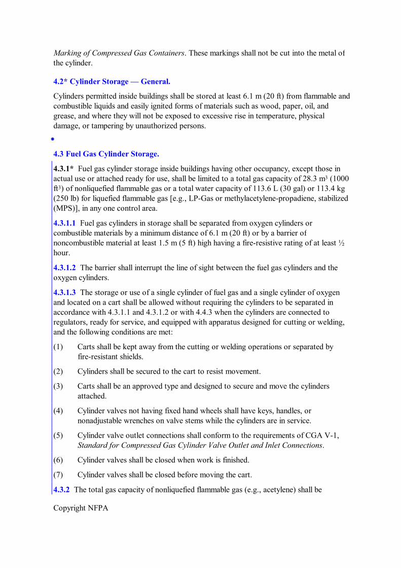
8.4.3.7 If acetylene is used from the gas holder without increase in pressure at some points but with increase in pressure by a compressor or booster pump at other points, piping protective devices shall be installed in each supply line. The lowpressure protective device shall be located between the gas holder and the shop piping, and the mediumpressure protective device shall be located between the compressor or booster pump and the shop piping. (See Figure 8.4.3.7.)
FIGURE 8.4.3.7 Protective Devices for Gas Holders, Compressors, and Booster Pumps.
8.4.4 Acetylene Compressor and Booster Pump Equipment.
8.4.4.1 Compressors and booster pumps shall be listed or approved.

Copyright NFPA
8.4.4.2 Wiring and electrical equipment in compressor or booster pump rooms or enclosures shall conform to the provisions of Article 501 of NFPA 70, National Electrical Code, for Class I, Division 2 or Class I, Zone 2 locations.
8.4.4.3 Compressor or booster pumps shall be provided with pressurerelief valves that will relieve gauge pressure exceeding 103 kPa (15 psi) by venting the gas to a safe outdoor location as provided in 8.4.2.3 or by returning the gas to the inlet side or to the gas supply source.
8.4.4.4 Compressors or booster pumps cooled by water recirculation shall be provided with interlocks to shut down the compressors or pumps in event of cooling water supply failure.
8.4.4.5 Compressor or booster discharge outlets shall be provided with piping protective equipment. (See Section 7.3.)
8.4.4.6 Compressors and booster pump equipment shall be located in wellventilated areas away from open flames, electrical or mechanical sparks, or other ignition sources.
8.5* Outside Generator Houses and Inside Generator Rooms for Stationary Acetylene Generators.
8.5.1 Construction.
8.5.1.1 Openings in any outside generator house shall not be located within 1.5 m (5 ft ) of any opening in another building.
8.5.1.2 Walls, floors, and roofs of outside generator houses shall be constructed of noncombustible or limitedcombustible materials.
8.5.1.3 Means of egress shall comply with high hazard occupancy requirements in NFPA 101, Life Safety Code.
8.5.1.4 Buildings in which acetylene generators are located shall not exceed one story in height, except that generators shall be permitted to be installed on the top floor or roof of a multi or singlestory building.
8.5.1.5 Generators installed inside buildings in which calcium carbide is used in amounts exceeding the maximum allowable quantity shall be in rooms constructed to meet Protection Level 2 requirements.
8.5.1.6 Calcium carbide exceeding 273 kg (600 lb) but not exceeding 2273 kg (5000 lb) shall be stored under one of the following conditions:
(1) In accordance with 8.5.1.7
(2) In an inside generator room or an outside generator house
(3) In a separate room in a onestory building that can contain other occupancies but without cellar or basement beneath the carbide storage section; such rooms shall be constructed in accordance with 8.5.1.6 and 8.5.1.7 and shall be used for no other purpose
8.5.1.7 Explosion control shall be in accordance with NFPA 5000, Building Construction

Copyright NFPA
and Safety Code, for high hazard Level 2 contents.
8.5.2 Ventilation. Ventilation shall be in accordance with Section 6.16 of NFPA 55, Standard for the Storage, Use, and Handling of Compressed Gases and Cryogenic Fluids in Portable and Stationary Containers, Cylinders, and Tanks.
8.5.3 Heating Systems, Electrical Equipment, and Sources of Ignition.
8.5.3.1 Heating shall be by steam, hot water, or other indirect means. Heating by flames or fires shall be prohibited in outside generator houses, in inside generator rooms, and in any enclosure communicating with them.
8.5.3.2 Electrical equipment and wiring in outside generator houses or inside generator rooms shall conform to the provisions of Article 501 of NFPA 70, National Electrical Code, for Class I, Division 2 or Class I, Zone 2 locations.
8.5.3.3 Sources of ignition shall be prohibited in outside generator houses or inside generator rooms.
Chapter 9 Calcium Carbide Storage
9.1 Packaging.
9.1.1 Calcium carbide shall be stored in packages meeting DOT or TC regulations.
9.1.2 Packages containing calcium carbide shall be conspicuously marked “Calcium Carbide — Dangerous If Not Kept Dry” or with equivalent warning.
9.2 Storage in Buildings.
9.2.1 Storage of calcium carbide inside buildings in aggregate quantities exceeding the maximum allowable quantity for Class 2 waterreactive solids in accordance with NFPA 5000, Building Construction and Safety Code, shall be in buildings, rooms or areas constructed and protected in accordance with NFPA 5000, for high hazard Level 3 contents.
9.2.2 Calcium carbide in sealed packages, except as provided for in 9.3 shall be permitted to be stored inside buildings or in the same room with fuel gas cylinders provided the aggregate quantities do not exceed the maximum quantities set forth in 9.2.1, 4.3.1, and 4.3.2.
9.3 Storage Outside Buildings.
9.3.1 Calcium carbide in unopened containers in good condition (watertight and airtight) shall be permitted to be stored outdoors.
9.3.2 Containers shall be stored horizontally in single or double rows. The bottom tier of each row shall be placed on wooden planking or equivalent so that the containers will not come in contact with the ground or ground water.
9.3.3 Storage areas shall be at least 3 m (10 ft) from lines of adjoining property that may be

Copyright NFPA
built upon.
Chapter 10 Mobile Acetylene Trailer Systems
10.1 General Provisions.
The mobile acetylene trailer system and discharging of the trailer system shall comply with CGA G1.6, Recommended Practices for Mobile Acetylene Trailer Systems.
10.2 Discharge Stations at Consumer Sites.
10.2.1 The discharge station site shall be outdoors or in a separate building used for that purpose exclusively. The site shall be such that the trailer and associated equipment shall not be beneath or exposed to failure of electric power lines, flammable or combustible liquid lines, or flammable gas lines.
10.2.2 Minimum distances from the trailer, the trailer discharge connection, or a building housing the trailer to exposures shall be as shown in Table 10.2.2.
Table 10.2.2 Separation Distances from Trailer Discharge Connection or Building Housing Trailer to Exposures
Exposure
Property line Buildings constructed of combustible materials Buildings constructed of noncombustible or limitedcombustible materials Bulk oxygen systems All classes of flammable and combustible liquid storage aboveground All classes of flammable and combustible liquid belowground Tank Vent or fill opening of tank Other flammable gas storage
10.2.3 The site shall be located so as to be readily accessible and to provide adequate space for trailer positioning.
10.2.4 The site shall be posted “Acetylene — Flammable Gas — No Smoking — No Open Flames” or equivalent.
10.2.5 The mobile acetylene trailer system shall be electrically bonded and grounded.
10.2.6 Acetylene meters, where utilized, shall be a type recommended by the meter manufacturer for acetylene service and shall operate at gauge pressures not to exceed 103 kPa (15 psi).
10.2.7 Where protective walls or roofs are provided on outdoor installations, they shall be constructed of noncombustible (see 3.3.13) or limitedcombustible materials (see 3.3.8).

Copyright NFPA
10.2.8 Electrical equipment within 4.6 m (15 ft) of outdoor installations shall be in accordance with Article 501 of NFPA 70, National Electrical Code, for Class I, Division 2 or Class I, Zone 2 locations.
10.3 Indoor Discharge Stations.
10.3.1 Separate buildings housing mobile acetylene trailer systems shall be constructed of noncombustible or limitedcombustible materials. Heating, if provided, shall be by steam, hot water, or other indirect means.
10.3.2 Adequate ventilation to the outdoors shall be provided. Inlet openings shall be located near the floor in exterior walls only. Outlet openings shall be located at the high point of the room in exterior walls or roof. Inlet and outlet openings shall each have a minimum total area of 0.1 m 2 per 28.3 m 3 (1 ft 2 per 1000 ft 3 ) of room volume.
10.3.3 Explosion venting shall be provided in exterior walls or roof only. The venting area shall be equal to not less than 0.1 m 2 per 1.4 m 3 (1 ft 2 per 50 ft 3 ) of room volume. Vents shall be permitted to consist of any one or any combination of the following, designed to relieve at a maximum pressure of 1.2 kPa (25 lb per ft 2 ): walls of light material, lightly fastened hatch covers, lightly fastened, outwardopening swinging doors in exterior walls, and lightly fastened walls or roof.
10.3.4 Electrical equipment shall be in accordance with Article 501 of NFPA 70, National Electrical Code, for Class I, Division 2 or Class I, Zone 2 locations.
10.3.5 There shall be no sources of ignition, such as from open flames, electrical equipment, or heating equipment, in the indoor discharge station.
10.4 Instructions.
10.4.1 For installations requiring any equipment operation by the user, legible instructions shall be posted and maintained at the discharge station.
10.4.2 A trained person shall be in attendance while the mobile acetylene trailer is being connected to or disconnected from the discharge station piping and during any manual valve operations.
10.5* Fire Protection.
10.5.1* Areas devoted to discharging mobile acetylene trailer systems shall be provided with fire hoses or fixed water spray systems. Fire extinguishers of the dry chemical or carbon dioxide type shall be provided.
10.5.2 Fire protection equipment shall be conspicuously located and posted so that it is visible and accessible in an emergency. Fire hoses and fixed water spray system control valves shall be located so that they can be operated from outdoors.
10.5.3 Exits and fire protection equipment shall not be blocked or obstructed in any manner.

Copyright NFPA
Annex A Explanatory Material
Annex A is not a part of the requirements of this NFPA document but is included for informational purposes only. This annex contains explanatory material, numbered to correspond with the applicable text paragraphs.
A.1.1.5(1) For information on safety in welding and cutting, see ANSI Z49.1, Safety in Welding, Cutting, and Allied Processes.
A.1.7 Compatibility involves both combustibility and ease of ignition. Materials that burn in air will burn violently in pure oxygen at normal pressure and explosively in pressurized oxygen. Also, many materials that do not burn in air will do so in pure oxygen, particularly under pressure. Metals for containers and piping must be selected carefully, depending on service conditions. The various steels are acceptable for many applications, but some service conditions can call for other materials (usually copper or its alloys) because of their greater resistance to ignition and lower rate of combustion.
Similarly, materials that can be ignited in air have lower ignition energies in oxygen. Many such materials can be ignited by friction at a valve seat or stem packing or by adiabatic compression produced when oxygen at high pressure is introduced rapidly into a system initially at low pressure.
A.3.2.1 Approved. The National Fire Protection Association does not approve, inspect, or certify any installations, procedures, equipment, or materials; nor does it approve or evaluate testing laboratories. In determining the acceptability of installations, procedures, equipment, or materials, the authority having jurisdiction may base acceptance on compliance with NFPA or other appropriate standards. In the absence of such standards, said authority may require evidence of proper installation, procedure, or use. The authority having jurisdiction may also refer to the listings or labeling practices of an organization that is concerned with product evaluations and is thus in a position to determine compliance with appropriate standards for the current production of listed items.
A.3.2.2 Authority Having Jurisdiction (AHJ). The phrase “authority having jurisdiction,” or its acronym AHJ, is used in NFPA documents in a broad manner, since jurisdictions and approval agencies vary, as do their responsibilities. Where public safety is primary, the authority having jurisdiction may be a federal, state, local, or other regional department or individual such as a fire chief; fire marshal; chief of a fire prevention bureau, labor department, or health department; building official; electrical inspector; or others having statutory authority. For insurance purposes, an insurance inspection department, rating bureau, or other insurance company representative may be the authority having jurisdiction. In many circumstances, the property owner or his or her designated agent assumes the role of the authority having jurisdiction; at government installations, the commanding officer or departmental official may be the authority having jurisdiction.
A.3.2.4 Listed. The means for identifying listed equipment may vary for each organization concerned with product evaluation; some organizations do not recognize equipment as listed unless it is also labeled. The authority having jurisdiction should utilize the system employed

Copyright NFPA
by the listing organization to identify a listed product.
A.3.3.6 DOT. Prior to April 1, 1967, DOT regulations and specifications referenced in this standard were promulgated by the Interstate Commerce Commission (ICC).
A.3.3.12 Mobile Acetylene Trailer System. This system includes the mobile acetylene trailer, pressure regulator(s), flash arresters, protective devices, meter (optional), and interconnecting piping. The system terminates at the point where acetylene at service pressure enters the user’s piping system.
A.3.3.14 P F Device. A wet P F device is commonly known as a hydraulic seal, a hydraulic valve, or a hydraulic backpressure valve.
A.3.3.16 Piping. The piping includes some or all of the following:
(1) Main piping — piping leading directly from the gas supply source to branch or outlet piping
(2) Branch piping — piping leading from the main piping to outlet piping
(3) Outlet piping — piping leading to station outlets, either from branch piping or directly from main piping
A.3.3.19 Portable Outlet Header. These devices are commonly used at piers and dry docks in shipyards where the permanent piping system station outlets cannot be located close enough to the work to provide a direct supply.
A.3.3.20 PressureRelief Device. It can be of the springloaded, weightloaded, or rupturedisc type.
A.4.2 Storage of cylinders of dissolved acetylene with the valve end up minimizes the possibility of liquid solvent being discharged.
A.4.3.1 A water capacity of 334 kg (735 lb) is equivalent to about 140 kg (309 lb) of propane, 167 kg (368 lb) of methylacetylenepropadiene, stabilized, or 170 kg (375 lb) of butane.
A.5.1.2 A water capacity of 334 kg (735 lb) is equivalent to about 140 kg (309 lb) of propane, 167 kg (368 lb) of MPS, or 170 kg (375 lb) of butane.
A.6.1.2.1 For information on materials, fabrication, installation, cleaning, and testing of piping systems for oxygen service, see CGA G4.4, Industrial Practices for Gaseous Oxygen Transmission and Distribution Piping Systems.
A.6.1.3.3 The pressure limit of 206 kPa (30 psi) absolute is intended to prevent unsafe use of acetylene in pressurized environments such as caissons, underground excavations, or tunnel construction.
A.6.4 Also see CGA G4.1, Equipment Cleaned for Oxygen Service.
A.6.4.1 Hot water solutions of caustic soda or trisodium phosphate are effective cleaning agents for this purpose.
A.6.6.1 For information on marking of aboveground piping systems, see ANSI A13.1,

Copyright NFPA
Scheme for Identification of Piping Systems.
A.7.3.4 The options for the location of a P F device will depend on the size and complexity of the piping.
A.8.4.3.1 Gasometer: An apparatus that displaces water by the generation of acetylene gas into a gastight holder or container.
A.8.5 In this section, the word building means a building having occupancy other than that directly associated with the production of acetylene, the storage of calcium carbide, or the storage and manifolding of gases used in welding and cutting.
A.10.5 The major fire hazard on a mobile acetylene trailer system is that of acetylene gas escaping from equipment, piping, or cylinder fittings. The gas might or might not ignite. In either case, every attempt consistent with personnel safety is normally made to shut off or remove the source of escaping gas. Fire normally is not extinguished in any other way, but some fires in leaking acetylene have been extinguished with hose water or hand extinguishers when the source of escaping fuel was small enough so that it did not present a reignition hazard, or the source was removed safely and promptly to a safe location. When a fire has exposed acetylene cylinders, the cylinders have been kept cool by application of water to protect the cylinders and prevent undue release of acetylene through the cylinder fusible plug devices.
A.10.5.1 Combination stream fire hose nozzles of the solidtospray pattern are recommended for use in these areas.
For information on portable fire extinguishers, see NFPA 10, Standard for Portable Fire Extinguishers.
Annex B Informational References
B.1 Referenced Publications.
The documents or portions thereof listed in this annex are referenced within the informational sections of this standard and are not part of the requirements of this document unless also listed in Chapter 2 for other reasons.
B.1.1 NFPA Publications. National Fire Protection Association, 1 Batterymarch Park, Quincy, MA 021697471.
NFPA 10, Standard for Portable Fire Extinguishers, 2007 edition.
B.1.2 Other Publications.
B.1.2.1 ANSI Publications. American National Standards Institute, Inc., 25 West 43rd Street, 4th floor, New York, NY 10036.
ANSI Z49.1, Safety in Welding, Cutting, and Allied Processes, 1999.
B.1.2.2 ASME Publications. American Society of Mechanical Engineers, Three Park Avenue, New York, NY 100165990.

Copyright NFPA
ASME A13.1, Scheme for Identification of Piping Systems, 1996.
B.1.2.3 CGA Publications. Compressed Gas Association, 4221 Walney Road, 5th Floor, Chantilly, VA 201512923.
CGA G4.1, Equipment Cleaned for Oxygen Service, 1996.
CGA G4.4, Industrial Practices for Gaseous Oxygen Transmission and Distribution Piping Systems, 1993.
B.2 Informational References.
The following documents or portions thereof are listed here as informational resources only. They are not a part of the requirements of this document.
NFPA 96, Standard for Ventilation Control and Fire Protection of Commercial Cooking Operations, 2004 edition.
NFPA 255, Standard Method of Test of Surface Burning Characteristics of Building Materials, 2006 edition.
B.3 References for Extracts in Informational Sections. (Reserved)
Index
A Acetylene ........................................................see also Fuel gas
Booster pumps ............................................ 8.4.3.7, 8.4.4 Compressors ..............................................8.4.3.7, 8.4.4 Gas holders ................................................8.4.3, A.8.4.3.1 Generators .................................................. see Generators, acetylene Liquid ........................................................1.5.1 Lowpressure (definition) ............................ 3.3.1.1 Manifolds .................................................... 5.1.2, A.5.1.2 Mediumpressure (definition) ...................... 3.3.1.2 Piping ........................................................6.1.3, A.6.1.3.3
Allied processes ................................................ 1.1.1(1), 1.1.2 Definition .................................................... 3.3.2
Approved (definition) ......................................3.2.1, A.3.2.1 Authority having jurisdiction (definition) ..........3.2.2, A.3.2.2
B Backflow check valves ...................................... 7.4.2
Definition .................................................... 3.3.3 Backflow protection devices ............................7.3.5, 7.3.6, 7.4.7 Booster pumps, acetylene ................................8.4.4 Building construction

Copyright NFPA
Building construction Acetylene generators ..................................8.5.1 Discharge stations, mobile acetylene
trailers .................................................. 10.2.7, 10.3.1 to 10.3.3
C Calcium carbide storage .................................... 1.1.1(3)(b), Chap. 9
Acetylene generator houses or rooms .......... 8.5.1.5, 8.5.1.6 Buildings, storage in .................................... 9.2 Outside storage ..........................................9.3 Packaging ..................................................9.1
Compatibility, material–oxygen ........................1.7, A.1.7 Compressors, acetylene ....................................8.4.4 Containers ........................................................ see Cylinders Cylinders .......................................................... 1.8, Chap. 4
Definition .................................................... 3.3.4 Fabrication .................................................. 4.1.1, 4.1.2 Manifolding of ............................................ Chap. 5 Marking ...................................................... 4.1.1, 4.1.3 Storage ......................................................1.1.1(3)(a), 4.2 to 4.4, A.4.2, A.4.3.1
Definition .............................................. 3.3.5
D Definitions ........................................................ Chap. 3 Discharge stations, at consumer sites
Attendant .................................................... 10.4.2 Indoor (separate buildings) .......................... 10.2, 10.3 Instructions ................................................10.4 Outside ......................................................10.2
DOT Definition .................................................... 3.3.6 Service pressure .......................................... 5.2, 5.3
E Electrical equipment
Compressor or booster pump rooms ..........8.4.4.2 Discharge stations, at consumer sites ..........10.2.8, 10.3.4 Generator rooms or houses ........................8.5.3.2
Equivalency to standard .................................... 1.4 Exits ................................................................10.5.3 Explosion control, acetylene generator houses
or rooms .................................................... 8.5.1.7
Explosion vents ................................................ 10.3.3 Extinguishers, portable fire ..............................10.5.1, A.10.5.1

Copyright NFPA
Extinguishers, portable fire ..............................10.5.1, A.10.5.1
F Fire prevention practices ..................................1.6.2 Fire protection systems
Fuel gas cylinder storage ............................4.3.2 to 4.3.4 Mobile acetylene trailer systems .................. 10.5, A.10.5
Flashback protection devices ............................7.3.6, 7.4.7 Fuel gas
Cylinder storage .......................................... 4.3, 4.4.3, 5.2.2, A.4.3.1 Definition .................................................... 3.3.7 In liquid phase ............................................1.5 Manifolds .................................................... 5.1, A.5.1.2
G Gases, fuel ........................................................ see Fuel gas Gas holders, acetylene ......................................8.4.3, A.8.4.3.1 Generators, acetylene ........................................ Chap. 8
Listing and marking ....................................8.1 Location ....................................................8.3 Oxygen cylinder storage .............................. 4.4.1 Oxygen manifolds, location of ....................5.2.2 to 5.2.4 Rating and pressure limitations .................... 8.2 Stationary (automatic and nonautomatic) .... 8.4, A.8.4.3.1
Installation ............................................ 8.4.1 Outside houses and inside rooms for ...... 8.5, A.8.5
H Heating systems, generator rooms or houses ....8.5.3.1 Highpressure manifolds
Fuel gas ...................................................... 5.1.3 Oxygen ......................................................5.2
Definition .............................................. 3.3.10.1 Portable outlet headers ................................ 5.4.5
Hose and hose connections Fire hose ....................................................10.5.1, 10.5.2, A.10.5.1 Lowpressure oxygen manifolds .................. 5.3.2 Oxygen and fuel gas service ........................ 7.5 Oxygen piping systems ................................ 6.1.2.2 Portable outlet headers ................................ 5.4.3
I Ignition sources

Copyright NFPA
Ignition sources Compressor and booster pump location ......8.4.4.6 Discharge stations, acetylene ......................10.3.5 Generator rooms or houses ........................8.5.3.3
Indoor discharge stations .................................. 10.2, 10.3 Inside rooms, acetylene generators .................... 8.5, A.8.5 Inside storage of cylinders ................................4.2 to 4.4, A.4.2, A.4.3.1
J Joints, piping .................................................... 6.2
L Labeled (definition) ..........................................3.2.3 Limited combustible (definition) ........................ 3.3.8 Limitedcombustible material ............................ 8.5.1.2, 10.2.7, 10.3.1
Definition .................................................... 3.3.8 Listing/listed
Acetylene generators ..................................8.1 Compressors and booster pumps ................8.4.4.1 Definition .................................................... 3.2.4, A.3.2.4 Manifolds .................................................... 5.1.1, 5.2.1 Pressureregulating devices ........................5.2.6
Lowpressure manifolds, oxygen ......................see Oxygen manifolds LPGas ............................................................see also Fuel gas
Cylinder storage .......................................... 4.3.1, A.4.3.1 Manifolds .................................................... 5.1.2, A.5.1.2
M Machine (definition) .......................................... 3.3.9 Manifolds ........................................................Chap. 5
Definition .................................................... 3.3.10 Fuel gas ...................................................... 5.1, A.5.1.2 Oxygen ......................................................see Oxygen manifolds
Marking/signs Acetylene generators ..................................8.1 Cylinders ....................................................4.1.1, 4.1.3 Discharge stations, at consumer sites ..........10.2.4 Oxygen manifold ........................................5.3.5 Piping ........................................................6.6, A.6.6.1
Methylacetylenepropadiene, stabilized (MPS) ....................................................................
see also Fuel gas
Cylinder storage .......................................... 4.3.1, A.4.3.1 Definition .................................................... 3.3.11 Manifolds .................................................... 5.1.2, A.5.1.2

Copyright NFPA
Manifolds .................................................... 5.1.2, A.5.1.2 Piping ........................................................6.1.3, A.6.1.3.3
Mobile acetylene trailer systems ........................ Chap. 10 Definition .................................................... 3.3.12, A.3.3.12
N Noncombustible material ..................................8.5.1.2, 10.2.7, 10.3.1
Definition .................................................... 3.3.13
O Outside discharge stations, at consumer sites .... 10.2 Outside houses, acetylene generators ................ 8.5, A.8.5 Outside storage, calcium carbide ......................9.3 Oxygen ............................................................see also Oxygen manifolds
Bulk supply system ....................................5.2.5 Compatibility of system components ..........1.7, A.1.7 Cylinder storage .......................................... 4.4 Piping and piping systems ..........................6.1.2, 6.3.2, 6.4.1, 6.4.2, A.6.1.2.1, A.6.4.1
Oxygen manifolds Highpressure ............................................5.2
Definition .............................................. 3.3.10.1 Lowpressure .............................................. 5.3, 6.1.2.3
Definition .............................................. 3.3.10.2
P P F devices ........................................................7.3.2 to 7.3.6, 7.4.2.1, A.7.3.4
Definition .................................................... 3.3.14, A.3.3.14 Pipes
Definition .................................................... 3.3.15 Piping and piping systems ................................Chap. 6
For acetylene and methylacetylenepropadiene, stabilized ..............................................................
6.1.3, A.6.1.3.3
Cleaning ...................................................... 6.1.2.1, 6.4, A.6.4 Definitions .................................................. 3.3.16, 3.3.18, A.3.3.16 Installation .................................................. 6.1.2.1, 6.3 Joints .......................................................... 6.2 Oxygen ...................................................... 6.1.2, 6.3.2, 6.4.1, 6.4.2, A.6.1.2.1, A.6.4.1 Painting ......................................................6.6, A.6.6.1 Pressure relief for ........................................ 7.2 Protective equipment .................................. 7.1.2, 7.3, 8.4.3.7, 8.4.4.5, A.7.3.4 Signs ..........................................................6.6, A.6.6.1 Testing ........................................................ 6.1.2.1, 6.5

Copyright NFPA
Testing ........................................................ 6.1.2.1, 6.5 Piping components (definition) .......................... 3.3.17 Portable outlet headers ....................................5.4, 7.3.2, 7.5
Definition .................................................... 3.3.19, A.3.3.19 Pressureregulating devices ..............................6.1.2.3, 7.6 Pressurerelief devices
Acetylene generators ..................................8.4.1.5 Compressors and booster pumps ................8.4.4.3 Definition .................................................... 3.3.20, A.3.3.20 Piping systems ............................................ 7.2
Protective equipment ........................................ 5.4.8, Chap. 7, 8.4.3.7, 8.4.4.5 Psia (definition) ................................................3.3.21 Psig (definition) ................................................ 3.3.22 Purpose of standard .......................................... 1.2
R References ........................................................ Chap. 2, Annex B Retroactivity of standard ..................................1.3
S Safe practices ..................................................1.6.1 Scope of standard ............................................1.1, A.1.1.5(1) Shall (definition) ..............................................3.2.5 Should (definition) ............................................ 3.2.6 Shutoff valves ..................................................6.3.4, 6.6.3 Sprinkler systems .............................................. 4.3.2(1), 4.3.3 Station outlets ..................................................5.4.5, 5.4.6, 6.1.2.3, 6.6.2
Definition .................................................... 3.3.23 Protective equipment .................................. 7.4
Storage Calcium carbide .......................................... see Calcium carbide storage Cylinders ....................................................see Cylinders
T TC (definition) .................................................. 3.3.24 Testing, of piping systems ................................6.5
V Ventilation
Compressors and booster pump equipment ..............................................................
8.4.4.6
Discharge stations, acetylene ......................10.3.2 Generator rooms or houses ........................8.5.2

Copyright NFPA
Generator rooms or houses ........................8.5.2 Vent pipes, stationary generator ........................ 8.4.2 Vents, explosion ..............................................10.3.3
W Warning signs ..................................................see Marking/signs Water spray fixed systems ................................4.3.2(2), 10.5.1, 10.5.2, A.10.5.1