Embed Size (px)
Citation preview

1SLOU452–December 2016Submit Documentation Feedback
Copyright © 2016, Texas Instruments Incorporated
NFCLink Standalone Getting Started
Getting Started GuideSLOU452–December 2016
NFCLink Standalone Getting Started
This guide assists users in the initial firmware setup and demonstration of Peer-to-Peer mode,Reader/Writer mode, and Card Emulation mode of the TRF7970A BoosterPack™ plug-in module with anMSP430F5529 LaunchPad™ development kit. The guide explains how to flash the example firmware thatis provided by TI. Additionally, it describes how to implement the different modes with the NFCLinkStandalone GUI.
www.ti.com
2 SLOU452–December 2016Submit Documentation Feedback
Copyright © 2016, Texas Instruments Incorporated
NFCLink Standalone Getting Started
Contents1 Introduction ................................................................................................................... 32 Getting Started ............................................................................................................... 33 TI NFC Tool GUI ........................................................................................................... 124 Summary .................................................................................................................... 22
List of Figures
1 UniFlash Installation......................................................................................................... 42 Selecting .out File in UniFlash ............................................................................................. 53 Code Composer Studio™ IDE Installation ............................................................................... 64 CCS Import Project Window ............................................................................................... 75 Device Manager With LaunchPad™ Development Kit Shown as an Other Device ................................ 86 Update Driver Software Using Device Manager......................................................................... 97 Browse Computer for Driver Software................................................................................... 108 Location Of CDC Driver in Installed Firmware Package .............................................................. 119 TI NFC Tool Auto Connect................................................................................................ 1210 TI NFC Tool Manual Connect ............................................................................................ 1211 Antenna Location on DLP-7970ABP..................................................................................... 1312 Phone Correct and Incorrect Presentation to BoosterPack™ Plug-in Module ..................................... 1413 Tag Correct and Incorrect Presentation to BoosterPack™ Plug-in Module ........................................ 1514 BoosterPack™ Plug-in Module Correct and Incorrect Presentation to BoosterPack™ Plug-in Module ........ 1515 NFC Configuration Tab – P2P Configuration........................................................................... 1616 Peer-to-Peer Tab........................................................................................................... 1717 NFC Configuration Tab – RW Configuration ........................................................................... 1818 Reader/Writer Mode Tab .................................................................................................. 1919 NFC Configuration Tab – CE Configuration ............................................................................ 2020 Card Emulation Tab........................................................................................................ 2121 Advanced COM Tab ....................................................................................................... 21
TrademarksBoosterPack, LaunchPad, Code Composer Studio, MSP430 are trademarks of Texas Instruments.All other trademarks are the property of their respective owners.
www.ti.com Introduction
3SLOU452–December 2016Submit Documentation Feedback
Copyright © 2016, Texas Instruments Incorporated
NFCLink Standalone Getting Started
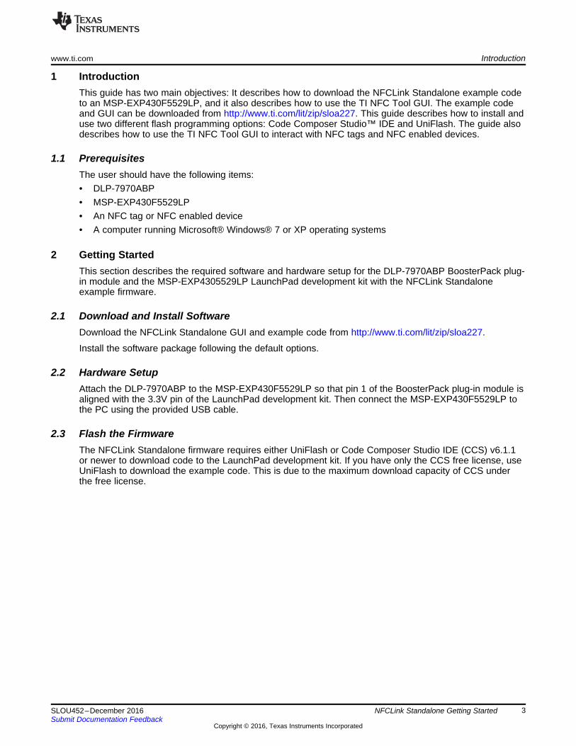
1 IntroductionThis guide has two main objectives: It describes how to download the NFCLink Standalone example codeto an MSP-EXP430F5529LP, and it also describes how to use the TI NFC Tool GUI. The example codeand GUI can be downloaded from http://www.ti.com/lit/zip/sloa227. This guide describes how to install anduse two different flash programming options: Code Composer Studio™ IDE and UniFlash. The guide alsodescribes how to use the TI NFC Tool GUI to interact with NFC tags and NFC enabled devices.
1.1 PrerequisitesThe user should have the following items:• DLP-7970ABP• MSP-EXP430F5529LP• An NFC tag or NFC enabled device• A computer running Microsoft® Windows® 7 or XP operating systems
2 Getting StartedThis section describes the required software and hardware setup for the DLP-7970ABP BoosterPack plug-in module and the MSP-EXP4305529LP LaunchPad development kit with the NFCLink Standaloneexample firmware.
2.1 Download and Install SoftwareDownload the NFCLink Standalone GUI and example code from http://www.ti.com/lit/zip/sloa227.
Install the software package following the default options.
2.2 Hardware SetupAttach the DLP-7970ABP to the MSP-EXP430F5529LP so that pin 1 of the BoosterPack plug-in module isaligned with the 3.3V pin of the LaunchPad development kit. Then connect the MSP-EXP430F5529LP tothe PC using the provided USB cable.
2.3 Flash the FirmwareThe NFCLink Standalone firmware requires either UniFlash or Code Composer Studio IDE (CCS) v6.1.1or newer to download code to the LaunchPad development kit. If you have only the CCS free license, useUniFlash to download the example code. This is due to the maximum download capacity of CCS underthe free license.
Getting Started www.ti.com
4 SLOU452–December 2016Submit Documentation Feedback
Copyright © 2016, Texas Instruments Incorporated
NFCLink Standalone Getting Started
2.3.1 Option 1: UniFlash
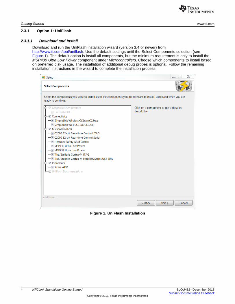
2.3.1.1 Download and InstallDownload and run the UniFlash installation wizard (version 3.4 or newer) fromhttp://www.ti.com/tool/uniflash. Use the default settings until the Select Components selection (seeFigure 1). The default option is install all components, but the minimum requirement is only to install theMSP430 Ultra Low Power component under Microcontrollers. Choose which components to install basedon preferred disk usage. The installation of additional debug probes is optional. Follow the remaininginstallation instructions in the wizard to complete the installation process.
Figure 1. UniFlash Installation
www.ti.com Getting Started
5SLOU452–December 2016Submit Documentation Feedback
Copyright © 2016, Texas Instruments Incorporated
NFCLink Standalone Getting Started
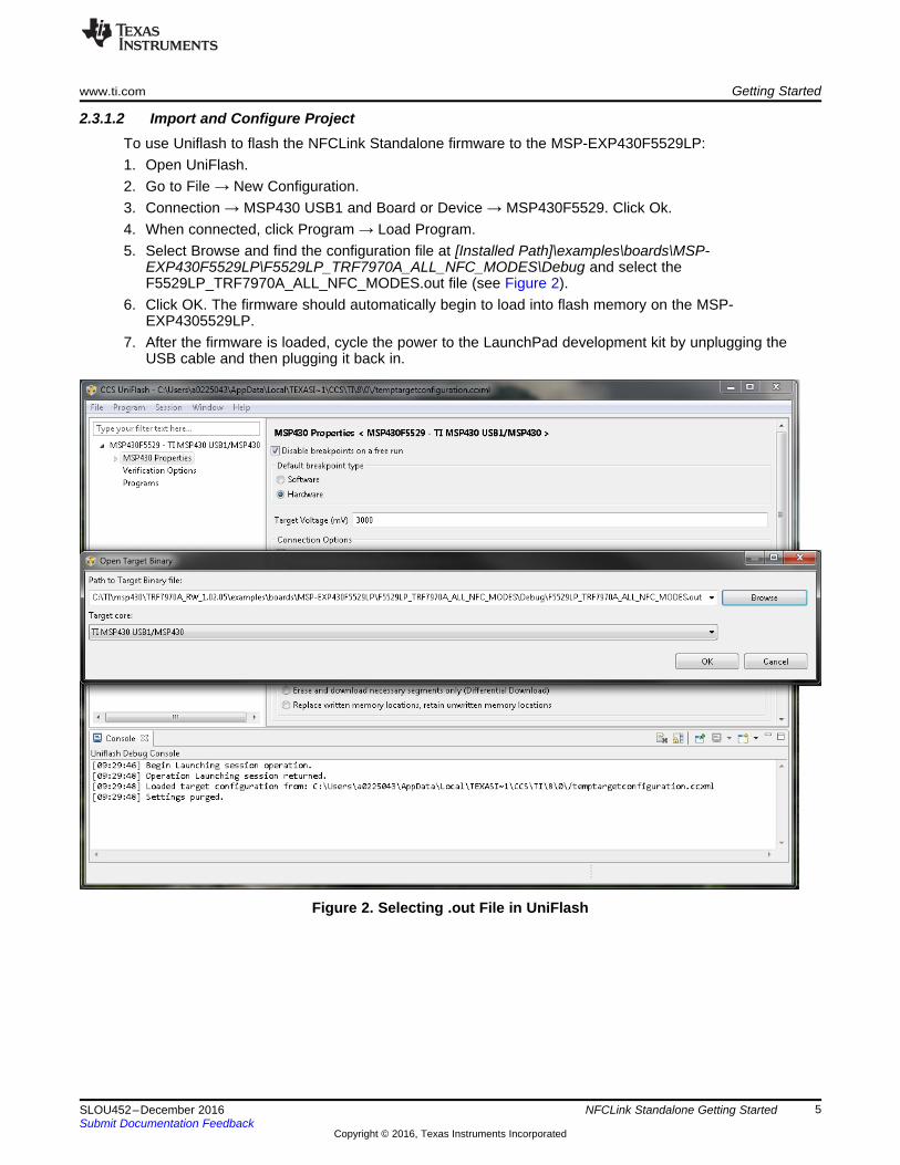
2.3.1.2 Import and Configure ProjectTo use Uniflash to flash the NFCLink Standalone firmware to the MSP-EXP430F5529LP:1. Open UniFlash.2. Go to File → New Configuration.3. Connection → MSP430 USB1 and Board or Device → MSP430F5529. Click Ok.4. When connected, click Program → Load Program.5. Select Browse and find the configuration file at [Installed Path]\examples\boards\MSP-
EXP430F5529LP\F5529LP_TRF7970A_ALL_NFC_MODES\Debug and select theF5529LP_TRF7970A_ALL_NFC_MODES.out file (see Figure 2).
6. Click OK. The firmware should automatically begin to load into flash memory on the MSP-EXP4305529LP.
7. After the firmware is loaded, cycle the power to the LaunchPad development kit by unplugging theUSB cable and then plugging it back in.
Figure 2. Selecting .out File in UniFlash
Getting Started www.ti.com
6 SLOU452–December 2016Submit Documentation Feedback
Copyright © 2016, Texas Instruments Incorporated
NFCLink Standalone Getting Started
2.3.2 Option 2: Code Composer Studio™ IDE (CCS)
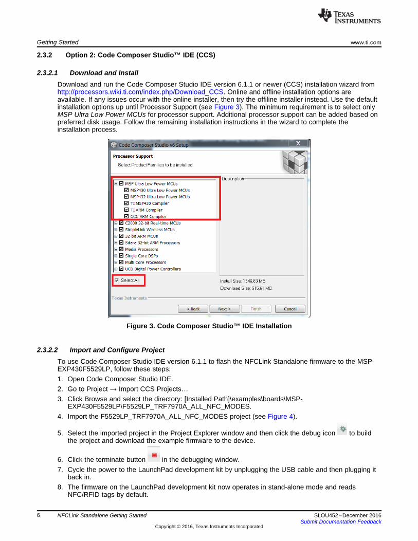
2.3.2.1 Download and InstallDownload and run the Code Composer Studio IDE version 6.1.1 or newer (CCS) installation wizard fromhttp://processors.wiki.ti.com/index.php/Download_CCS. Online and offline installation options areavailable. If any issues occur with the online installer, then try the offiline installer instead. Use the defaultinstallation options up until Processor Support (see Figure 3). The minimum requirement is to select onlyMSP Ultra Low Power MCUs for processor support. Additional processor support can be added based onpreferred disk usage. Follow the remaining installation instructions in the wizard to complete theinstallation process.
Figure 3. Code Composer Studio™ IDE Installation
2.3.2.2 Import and Configure ProjectTo use Code Composer Studio IDE version 6.1.1 to flash the NFCLink Standalone firmware to the MSP-EXP430F5529LP, follow these steps:1. Open Code Composer Studio IDE.2. Go to Project → Import CCS Projects…3. Click Browse and select the directory: [Installed Path]\examples\boards\MSP-
EXP430F5529LP\F5529LP_TRF7970A_ALL_NFC_MODES.4. Import the F5529LP_TRF7970A_ALL_NFC_MODES project (see Figure 4).
5. Select the imported project in the Project Explorer window and then click the debug icon to buildthe project and download the example firmware to the device.
6. Click the terminate button in the debugging window.7. Cycle the power to the LaunchPad development kit by unplugging the USB cable and then plugging it
back in.8. The firmware on the LaunchPad development kit now operates in stand-alone mode and reads
NFC/RFID tags by default.

www.ti.com Getting Started
7SLOU452–December 2016Submit Documentation Feedback
Copyright © 2016, Texas Instruments Incorporated
NFCLink Standalone Getting Started
9. If the CDC driver for the LaunchPad development kit is installed on the host PC, then the LaunchPaddevelopment kit is ready to connect to the TI NFC Tool GUI. See Section 2.4 for details on how todetermine if the CDC driver is installed.
Figure 4. CCS Import Project Window
Getting Started www.ti.com
8 SLOU452–December 2016Submit Documentation Feedback
Copyright © 2016, Texas Instruments Incorporated
NFCLink Standalone Getting Started
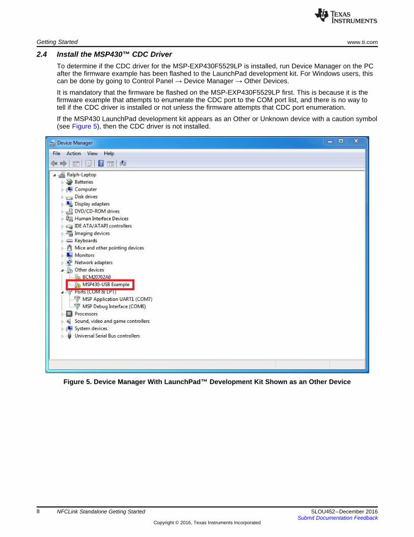
2.4 Install the MSP430™ CDC DriverTo determine if the CDC driver for the MSP-EXP430F5529LP is installed, run Device Manager on the PCafter the firmware example has been flashed to the LaunchPad development kit. For Windows users, thiscan be done by going to Control Panel → Device Manager → Other Devices.
It is mandatory that the firmware be flashed on the MSP-EXP430F5529LP first. This is because it is thefirmware example that attempts to enumerate the CDC port to the COM port list, and there is no way totell if the CDC driver is installed or not unless the firmware attempts that CDC port enumeration.
If the MSP430 LaunchPad development kit appears as an Other or Unknown device with a caution symbol(see Figure 5), then the CDC driver is not installed.
Figure 5. Device Manager With LaunchPad™ Development Kit Shown as an Other Device
www.ti.com Getting Started
9SLOU452–December 2016Submit Documentation Feedback
Copyright © 2016, Texas Instruments Incorporated
NFCLink Standalone Getting Started
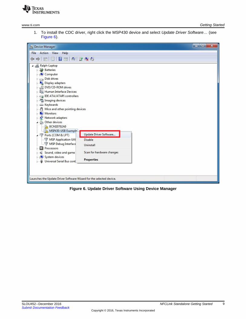
1. To install the CDC driver, right click the MSP430 device and select Update Driver Software… (seeFigure 6).
Figure 6. Update Driver Software Using Device Manager
Getting Started www.ti.com
10 SLOU452–December 2016Submit Documentation Feedback
Copyright © 2016, Texas Instruments Incorporated
NFCLink Standalone Getting Started
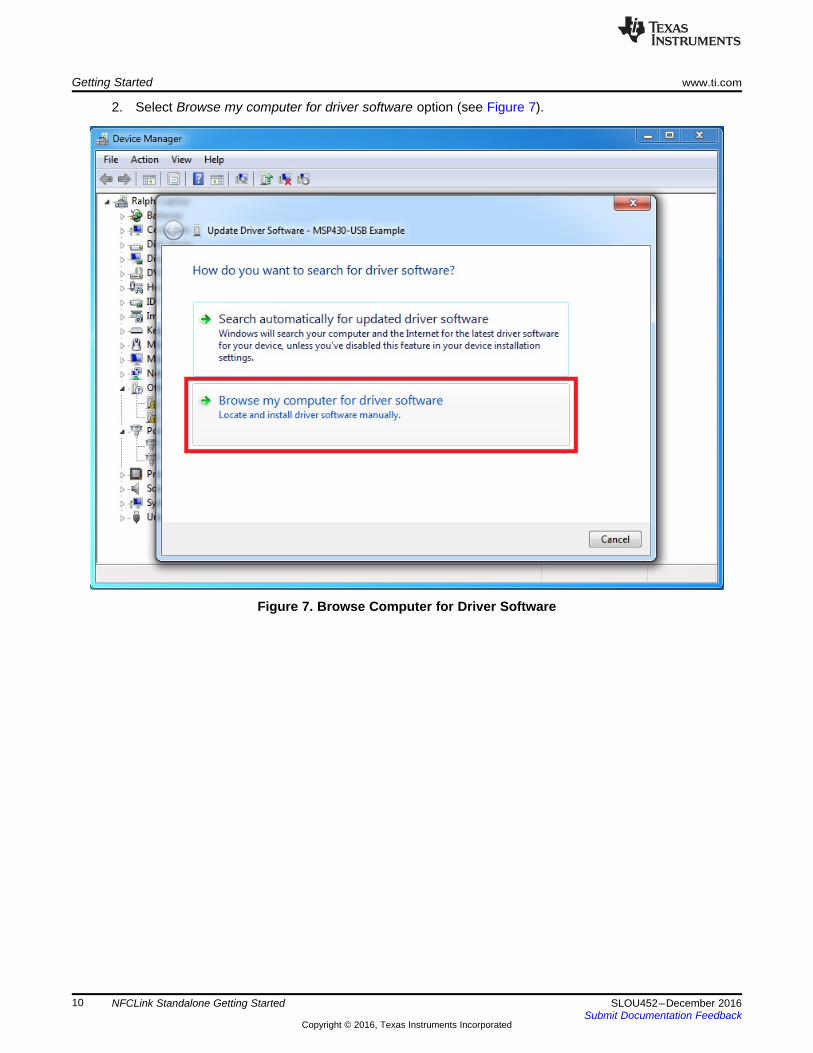
2. Select Browse my computer for driver software option (see Figure 7).
Figure 7. Browse Computer for Driver Software
www.ti.com Getting Started
11SLOU452–December 2016Submit Documentation Feedback
Copyright © 2016, Texas Instruments Incorporated
NFCLink Standalone Getting Started
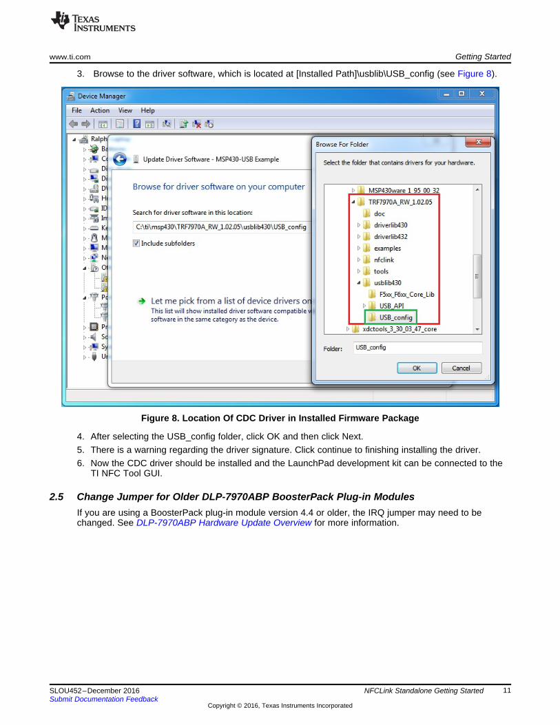
3. Browse to the driver software, which is located at [Installed Path]\usblib\USB_config (see Figure 8).
Figure 8. Location Of CDC Driver in Installed Firmware Package
4. After selecting the USB_config folder, click OK and then click Next.5. There is a warning regarding the driver signature. Click continue to finishing installing the driver.6. Now the CDC driver should be installed and the LaunchPad development kit can be connected to the
TI NFC Tool GUI.
2.5 Change Jumper for Older DLP-7970ABP BoosterPack Plug-in ModulesIf you are using a BoosterPack plug-in module version 4.4 or older, the IRQ jumper may need to bechanged. See DLP-7970ABP Hardware Update Overview for more information.
TI NFC Tool GUI www.ti.com
12 SLOU452–December 2016Submit Documentation Feedback
Copyright © 2016, Texas Instruments Incorporated
NFCLink Standalone Getting Started
3 TI NFC Tool GUIThis section describes the TI NFC Tool GUI, which gives users the ability to configure the NFCLinkStandalone firmware to communicate with NFC enabled devices using different modes and protocols. Thisguide describes use of version 1.8 of the TI NFC Tool. The TI NFC Tool GUI can be opened from theStart Menu under Programs → Texas Instruments → NFC Reader-Writer Application. Alternatively, it canbe found in the file system at [Install Path]\tools\TI NFC Tool\TI NFC Tool\bin\Debug.
3.1 How to Connect
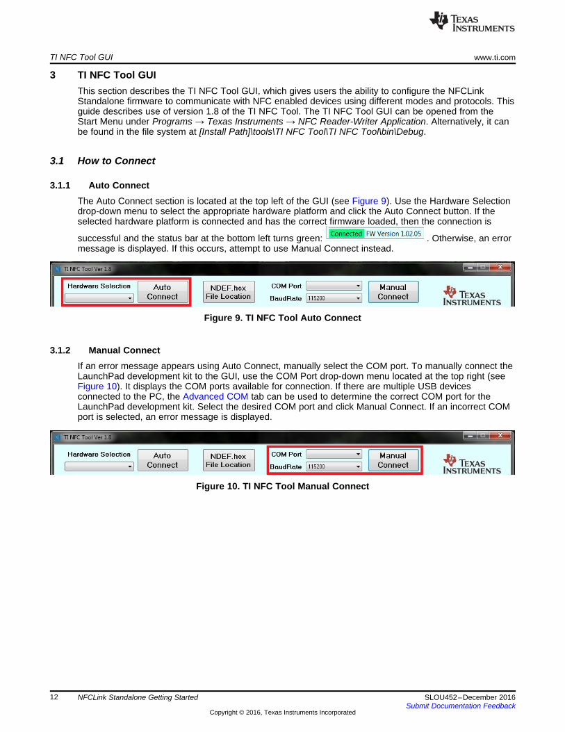
3.1.1 Auto ConnectThe Auto Connect section is located at the top left of the GUI (see Figure 9). Use the Hardware Selectiondrop-down menu to select the appropriate hardware platform and click the Auto Connect button. If theselected hardware platform is connected and has the correct firmware loaded, then the connection is
successful and the status bar at the bottom left turns green: . Otherwise, an errormessage is displayed. If this occurs, attempt to use Manual Connect instead.
Figure 9. TI NFC Tool Auto Connect
3.1.2 Manual ConnectIf an error message appears using Auto Connect, manually select the COM port. To manually connect theLaunchPad development kit to the GUI, use the COM Port drop-down menu located at the top right (seeFigure 10). It displays the COM ports available for connection. If there are multiple USB devicesconnected to the PC, the Advanced COM tab can be used to determine the correct COM port for theLaunchPad development kit. Select the desired COM port and click Manual Connect. If an incorrect COMport is selected, an error message is displayed.
Figure 10. TI NFC Tool Manual Connect
www.ti.com TI NFC Tool GUI
13SLOU452–December 2016Submit Documentation Feedback
Copyright © 2016, Texas Instruments Incorporated
NFCLink Standalone Getting Started
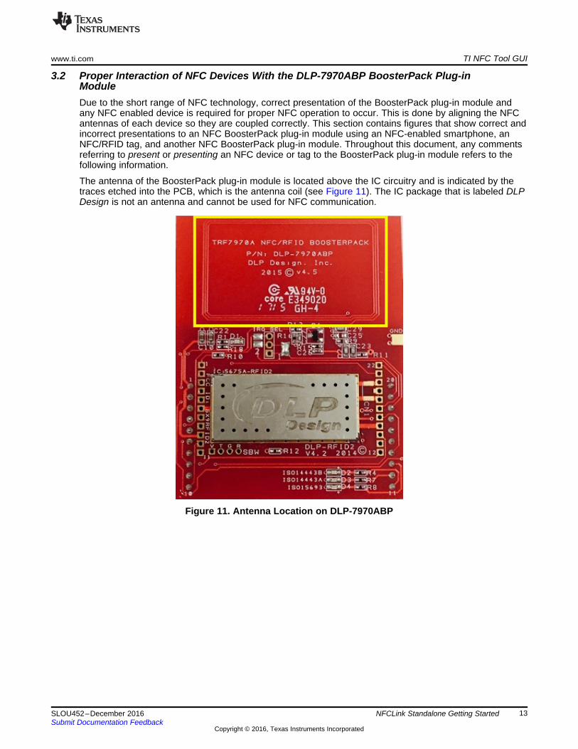
3.2 Proper Interaction of NFC Devices With the DLP-7970ABP BoosterPack Plug-inModuleDue to the short range of NFC technology, correct presentation of the BoosterPack plug-in module andany NFC enabled device is required for proper NFC operation to occur. This is done by aligning the NFCantennas of each device so they are coupled correctly. This section contains figures that show correct andincorrect presentations to an NFC BoosterPack plug-in module using an NFC-enabled smartphone, anNFC/RFID tag, and another NFC BoosterPack plug-in module. Throughout this document, any commentsreferring to present or presenting an NFC device or tag to the BoosterPack plug-in module refers to thefollowing information.
The antenna of the BoosterPack plug-in module is located above the IC circuitry and is indicated by thetraces etched into the PCB, which is the antenna coil (see Figure 11). The IC package that is labeled DLPDesign is not an antenna and cannot be used for NFC communication.
Figure 11. Antenna Location on DLP-7970ABP
TI NFC Tool GUI www.ti.com
14 SLOU452–December 2016Submit Documentation Feedback
Copyright © 2016, Texas Instruments Incorporated
NFCLink Standalone Getting Started
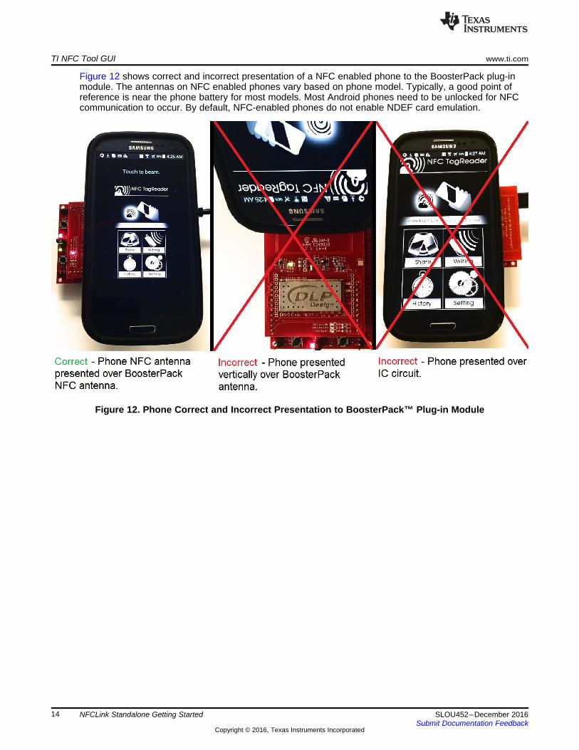
Figure 12 shows correct and incorrect presentation of a NFC enabled phone to the BoosterPack plug-inmodule. The antennas on NFC enabled phones vary based on phone model. Typically, a good point ofreference is near the phone battery for most models. Most Android phones need to be unlocked for NFCcommunication to occur. By default, NFC-enabled phones do not enable NDEF card emulation.
Figure 12. Phone Correct and Incorrect Presentation to BoosterPack™ Plug-in Module
www.ti.com TI NFC Tool GUI
15SLOU452–December 2016Submit Documentation Feedback
Copyright © 2016, Texas Instruments Incorporated
NFCLink Standalone Getting Started
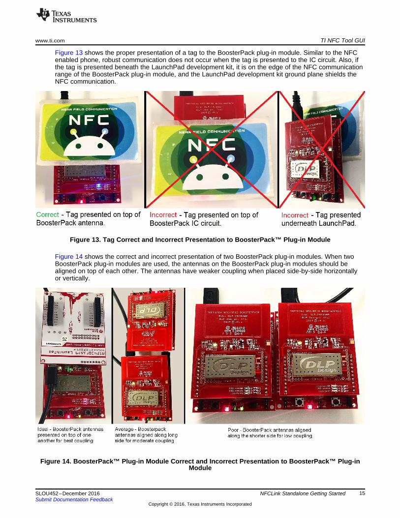
Figure 13 shows the proper presentation of a tag to the BoosterPack plug-in module. Similar to the NFCenabled phone, robust communication does not occur when the tag is presented to the IC circuit. Also, ifthe tag is presented beneath the LaunchPad development kit, it is on the edge of the NFC communicationrange of the BoosterPack plug-in module, and the LaunchPad development kit ground plane shields theNFC communication.
Figure 13. Tag Correct and Incorrect Presentation to BoosterPack™ Plug-in Module
Figure 14 shows the correct and incorrect presentation of two BoosterPack plug-in modules. When twoBoosterPack plug-in modules are used, the antennas on the BoosterPack plug-in modules should bealigned on top of each other. The antennas have weaker coupling when placed side-by-side horizontallyor vertically.
Figure 14. BoosterPack™ Plug-in Module Correct and Incorrect Presentation to BoosterPack™ Plug-inModule
TI NFC Tool GUI www.ti.com
16 SLOU452–December 2016Submit Documentation Feedback
Copyright © 2016, Texas Instruments Incorporated
NFCLink Standalone Getting Started
3.3 NFC Operation ModesNear Field Communication (NFC) offers three different modes of operation: Peer-to-Peer (P2P),Reader/Writer (RW), and Card Emulation (CE). This section discusses operation of each mode with theNFCLink Standalone GUI. For more information on NFC, visit www.ti.com/NFC.
3.3.1 Peer-to-Peer ModePeer-to-Peer (P2P) mode allows two NFC-enabled devices to communicate bidirectionally where bothdevices are able to initiate communication as needed.
Common use cases for P2P include sharing content from device to device, firmware updates, and pairingapplications.
For detailed information about how Peer-to-Peer communication operates with the TRF7970A, see NFCActive and Passive Peer-to-Peer Communication Using the TRF7970A.
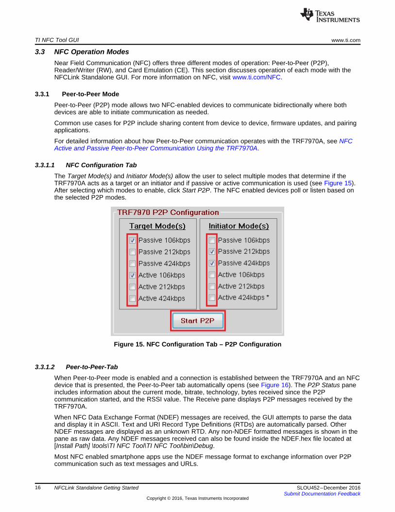
3.3.1.1 NFC Configuration TabThe Target Mode(s) and Initiator Mode(s) allow the user to select multiple modes that determine if theTRF7970A acts as a target or an initiator and if passive or active communication is used (see Figure 15).After selecting which modes to enable, click Start P2P. The NFC enabled devices poll or listen based onthe selected P2P modes.
Figure 15. NFC Configuration Tab – P2P Configuration
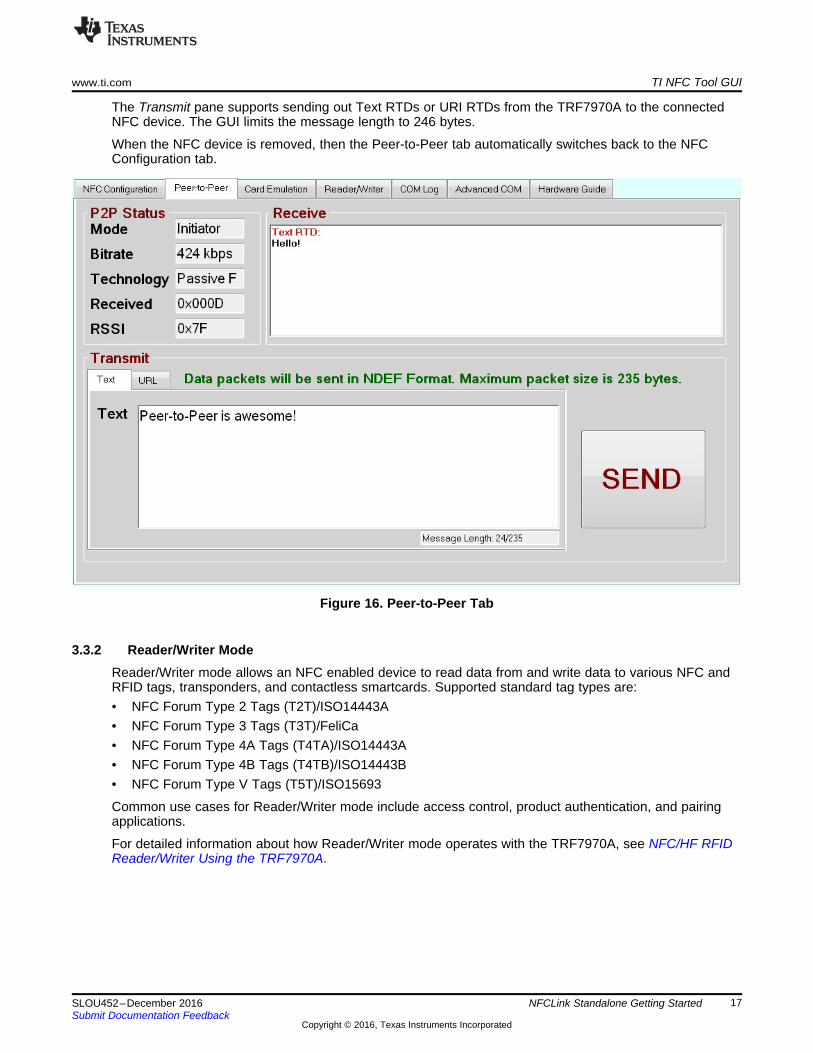
3.3.1.2 Peer-to-Peer-TabWhen Peer-to-Peer mode is enabled and a connection is established between the TRF7970A and an NFCdevice that is presented, the Peer-to-Peer tab automatically opens (see Figure 16). The P2P Status paneincludes information about the current mode, bitrate, technology, bytes received since the P2Pcommunication started, and the RSSI value. The Receive pane displays P2P messages received by theTRF7970A.
When NFC Data Exchange Format (NDEF) messages are received, the GUI attempts to parse the dataand display it in ASCII. Text and URI Record Type Definitions (RTDs) are automatically parsed. OtherNDEF messages are displayed as an unknown RTD. Any non-NDEF formatted messages is shown in thepane as raw data. Any NDEF messages received can also be found inside the NDEF.hex file located at[Install Path] \tools\TI NFC Tool\TI NFC Tool\bin\Debug.
Most NFC enabled smartphone apps use the NDEF message format to exchange information over P2Pcommunication such as text messages and URLs.
www.ti.com TI NFC Tool GUI
17SLOU452–December 2016Submit Documentation Feedback
Copyright © 2016, Texas Instruments Incorporated
NFCLink Standalone Getting Started
The Transmit pane supports sending out Text RTDs or URI RTDs from the TRF7970A to the connectedNFC device. The GUI limits the message length to 246 bytes.
When the NFC device is removed, then the Peer-to-Peer tab automatically switches back to the NFCConfiguration tab.
Figure 16. Peer-to-Peer Tab
3.3.2 Reader/Writer ModeReader/Writer mode allows an NFC enabled device to read data from and write data to various NFC andRFID tags, transponders, and contactless smartcards. Supported standard tag types are:• NFC Forum Type 2 Tags (T2T)/ISO14443A• NFC Forum Type 3 Tags (T3T)/FeliCa• NFC Forum Type 4A Tags (T4TA)/ISO14443A• NFC Forum Type 4B Tags (T4TB)/ISO14443B• NFC Forum Type V Tags (T5T)/ISO15693
Common use cases for Reader/Writer mode include access control, product authentication, and pairingapplications.
For detailed information about how Reader/Writer mode operates with the TRF7970A, see NFC/HF RFIDReader/Writer Using the TRF7970A.
TI NFC Tool GUI www.ti.com
18 SLOU452–December 2016Submit Documentation Feedback
Copyright © 2016, Texas Instruments Incorporated
NFCLink Standalone Getting Started
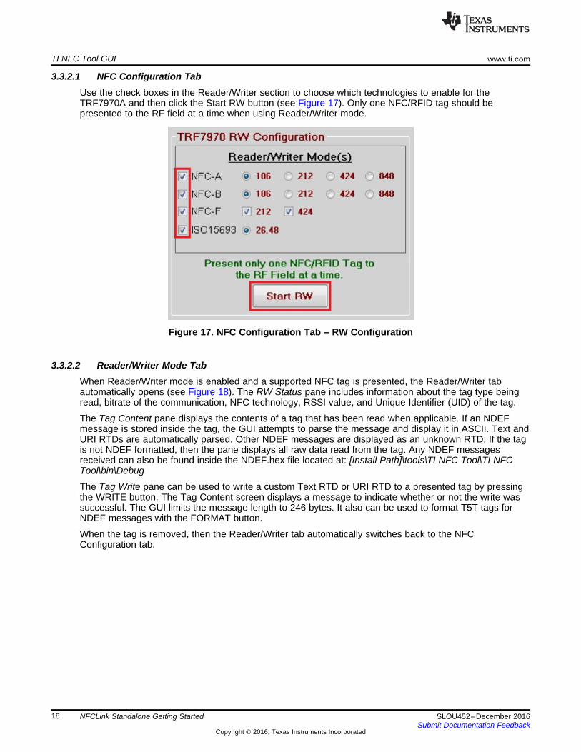
3.3.2.1 NFC Configuration TabUse the check boxes in the Reader/Writer section to choose which technologies to enable for theTRF7970A and then click the Start RW button (see Figure 17). Only one NFC/RFID tag should bepresented to the RF field at a time when using Reader/Writer mode.
Figure 17. NFC Configuration Tab – RW Configuration
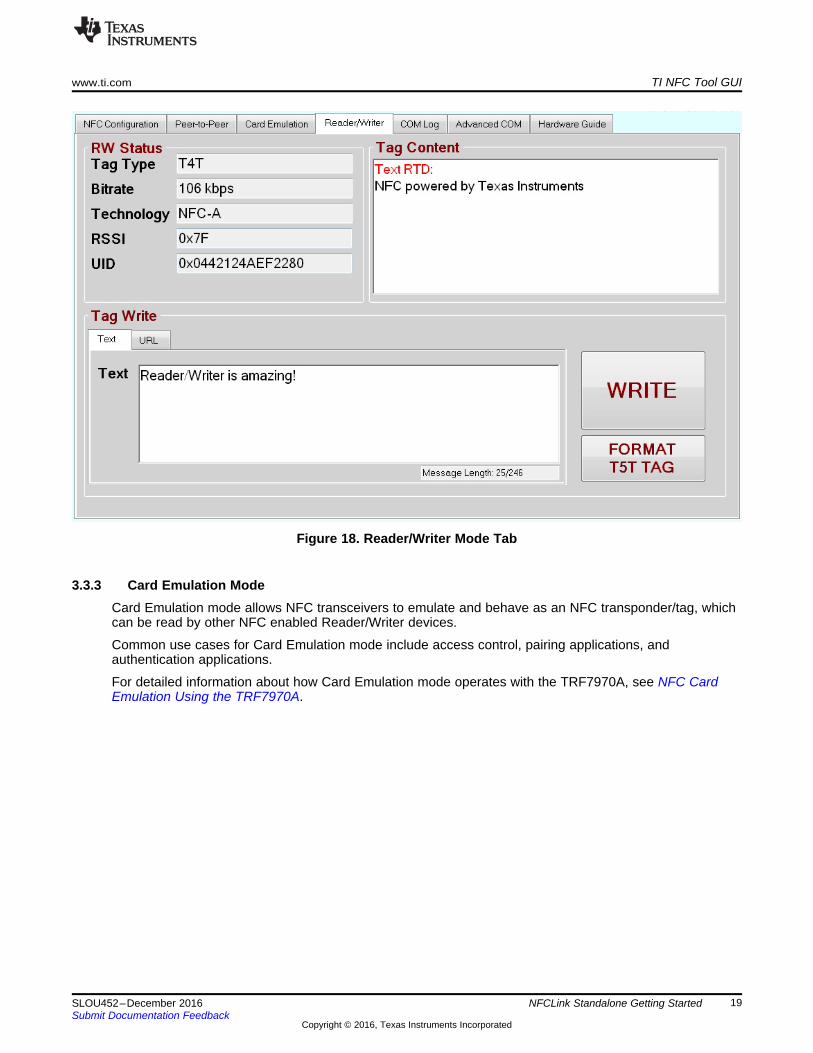
3.3.2.2 Reader/Writer Mode TabWhen Reader/Writer mode is enabled and a supported NFC tag is presented, the Reader/Writer tabautomatically opens (see Figure 18). The RW Status pane includes information about the tag type beingread, bitrate of the communication, NFC technology, RSSI value, and Unique Identifier (UID) of the tag.
The Tag Content pane displays the contents of a tag that has been read when applicable. If an NDEFmessage is stored inside the tag, the GUI attempts to parse the message and display it in ASCII. Text andURI RTDs are automatically parsed. Other NDEF messages are displayed as an unknown RTD. If the tagis not NDEF formatted, then the pane displays all raw data read from the tag. Any NDEF messagesreceived can also be found inside the NDEF.hex file located at: [Install Path]\tools\TI NFC Tool\TI NFCTool\bin\Debug
The Tag Write pane can be used to write a custom Text RTD or URI RTD to a presented tag by pressingthe WRITE button. The Tag Content screen displays a message to indicate whether or not the write wassuccessful. The GUI limits the message length to 246 bytes. It also can be used to format T5T tags forNDEF messages with the FORMAT button.
When the tag is removed, then the Reader/Writer tab automatically switches back to the NFCConfiguration tab.
www.ti.com TI NFC Tool GUI
19SLOU452–December 2016Submit Documentation Feedback
Copyright © 2016, Texas Instruments Incorporated
NFCLink Standalone Getting Started
Figure 18. Reader/Writer Mode Tab
3.3.3 Card Emulation ModeCard Emulation mode allows NFC transceivers to emulate and behave as an NFC transponder/tag, whichcan be read by other NFC enabled Reader/Writer devices.
Common use cases for Card Emulation mode include access control, pairing applications, andauthentication applications.
For detailed information about how Card Emulation mode operates with the TRF7970A, see NFC CardEmulation Using the TRF7970A.
TI NFC Tool GUI www.ti.com
20 SLOU452–December 2016Submit Documentation Feedback
Copyright © 2016, Texas Instruments Incorporated
NFCLink Standalone Getting Started
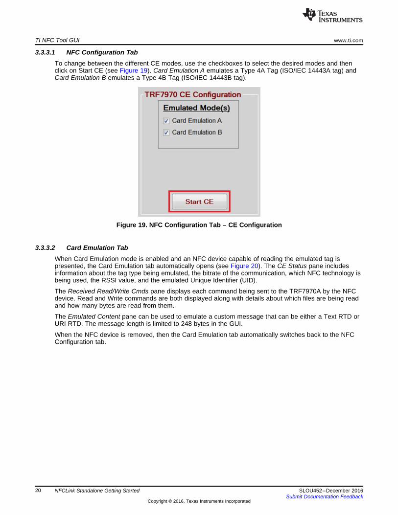
3.3.3.1 NFC Configuration TabTo change between the different CE modes, use the checkboxes to select the desired modes and thenclick on Start CE (see Figure 19). Card Emulation A emulates a Type 4A Tag (ISO/IEC 14443A tag) andCard Emulation B emulates a Type 4B Tag (ISO/IEC 14443B tag).
Figure 19. NFC Configuration Tab – CE Configuration
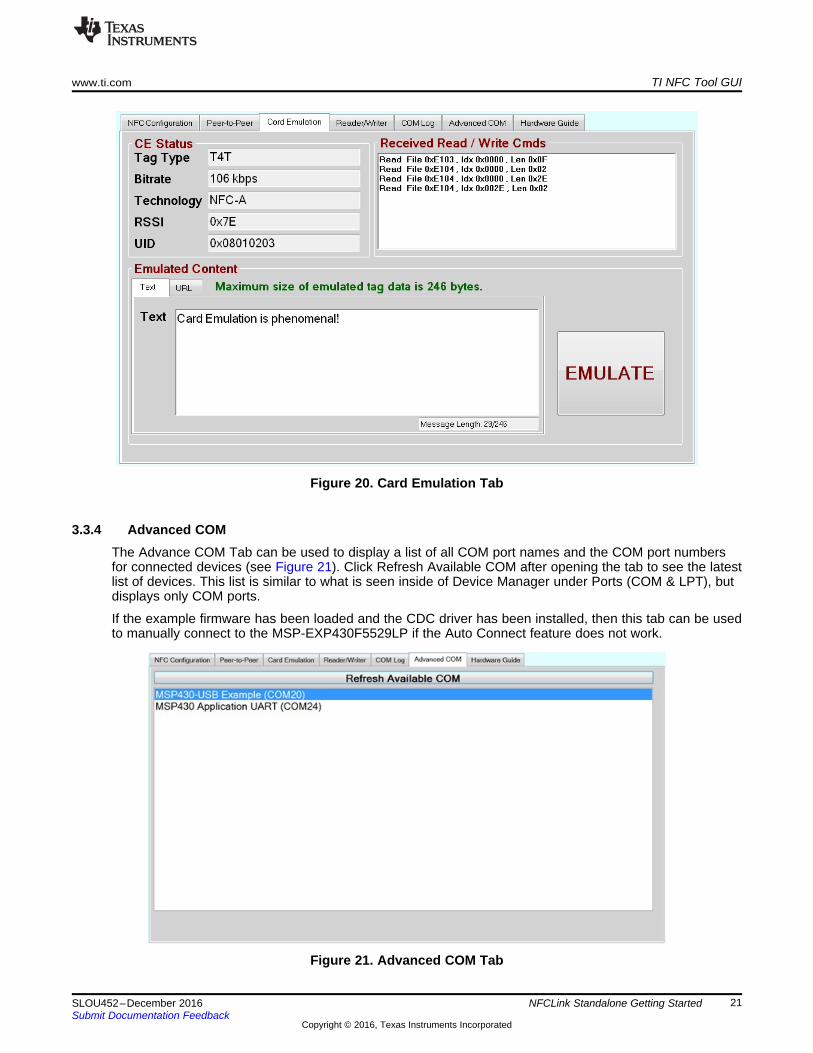
3.3.3.2 Card Emulation TabWhen Card Emulation mode is enabled and an NFC device capable of reading the emulated tag ispresented, the Card Emulation tab automatically opens (see Figure 20). The CE Status pane includesinformation about the tag type being emulated, the bitrate of the communication, which NFC technology isbeing used, the RSSI value, and the emulated Unique Identifier (UID).
The Received Read/Write Cmds pane displays each command being sent to the TRF7970A by the NFCdevice. Read and Write commands are both displayed along with details about which files are being readand how many bytes are read from them.
The Emulated Content pane can be used to emulate a custom message that can be either a Text RTD orURI RTD. The message length is limited to 248 bytes in the GUI.
When the NFC device is removed, then the Card Emulation tab automatically switches back to the NFCConfiguration tab.
www.ti.com TI NFC Tool GUI
21SLOU452–December 2016Submit Documentation Feedback
Copyright © 2016, Texas Instruments Incorporated
NFCLink Standalone Getting Started
Figure 20. Card Emulation Tab
3.3.4 Advanced COMThe Advance COM Tab can be used to display a list of all COM port names and the COM port numbersfor connected devices (see Figure 21). Click Refresh Available COM after opening the tab to see the latestlist of devices. This list is similar to what is seen inside of Device Manager under Ports (COM & LPT), butdisplays only COM ports.
If the example firmware has been loaded and the CDC driver has been installed, then this tab can be usedto manually connect to the MSP-EXP430F5529LP if the Auto Connect feature does not work.
Figure 21. Advanced COM Tab
Summary www.ti.com
22 SLOU452–December 2016Submit Documentation Feedback
Copyright © 2016, Texas Instruments Incorporated
NFCLink Standalone Getting Started
4 SummaryAfter the NFCLink Standalone GUI has been set up, refer to the following resources for further assistancein development:1. NFC Active and Passive Peer-to-Peer Communication Using the TRF7970A2. NFC/HF RFID Reader/Writer Using the TRF7970A3. NFC Card Emulation Using the TRF7970A
IMPORTANT NOTICE
Texas Instruments Incorporated and its subsidiaries (TI) reserve the right to make corrections, enhancements, improvements and otherchanges to its semiconductor products and services per JESD46, latest issue, and to discontinue any product or service per JESD48, latestissue. Buyers should obtain the latest relevant information before placing orders and should verify that such information is current andcomplete. All semiconductor products (also referred to herein as “components”) are sold subject to TI’s terms and conditions of salesupplied at the time of order acknowledgment.TI warrants performance of its components to the specifications applicable at the time of sale, in accordance with the warranty in TI’s termsand conditions of sale of semiconductor products. Testing and other quality control techniques are used to the extent TI deems necessaryto support this warranty. Except where mandated by applicable law, testing of all parameters of each component is not necessarilyperformed.TI assumes no liability for applications assistance or the design of Buyers’ products. Buyers are responsible for their products andapplications using TI components. To minimize the risks associated with Buyers’ products and applications, Buyers should provideadequate design and operating safeguards.TI does not warrant or represent that any license, either express or implied, is granted under any patent right, copyright, mask work right, orother intellectual property right relating to any combination, machine, or process in which TI components or services are used. Informationpublished by TI regarding third-party products or services does not constitute a license to use such products or services or a warranty orendorsement thereof. Use of such information may require a license from a third party under the patents or other intellectual property of thethird party, or a license from TI under the patents or other intellectual property of TI.Reproduction of significant portions of TI information in TI data books or data sheets is permissible only if reproduction is without alterationand is accompanied by all associated warranties, conditions, limitations, and notices. TI is not responsible or liable for such altereddocumentation. Information of third parties may be subject to additional restrictions.Resale of TI components or services with statements different from or beyond the parameters stated by TI for that component or servicevoids all express and any implied warranties for the associated TI component or service and is an unfair and deceptive business practice.TI is not responsible or liable for any such statements.Buyer acknowledges and agrees that it is solely responsible for compliance with all legal, regulatory and safety-related requirementsconcerning its products, and any use of TI components in its applications, notwithstanding any applications-related information or supportthat may be provided by TI. Buyer represents and agrees that it has all the necessary expertise to create and implement safeguards whichanticipate dangerous consequences of failures, monitor failures and their consequences, lessen the likelihood of failures that might causeharm and take appropriate remedial actions. Buyer will fully indemnify TI and its representatives against any damages arising out of the useof any TI components in safety-critical applications.In some cases, TI components may be promoted specifically to facilitate safety-related applications. With such components, TI’s goal is tohelp enable customers to design and create their own end-product solutions that meet applicable functional safety standards andrequirements. Nonetheless, such components are subject to these terms.No TI components are authorized for use in FDA Class III (or similar life-critical medical equipment) unless authorized officers of the partieshave executed a special agreement specifically governing such use.Only those TI components which TI has specifically designated as military grade or “enhanced plastic” are designed and intended for use inmilitary/aerospace applications or environments. Buyer acknowledges and agrees that any military or aerospace use of TI componentswhich have not been so designated is solely at the Buyer's risk, and that Buyer is solely responsible for compliance with all legal andregulatory requirements in connection with such use.TI has specifically designated certain components as meeting ISO/TS16949 requirements, mainly for automotive use. In any case of use ofnon-designated products, TI will not be responsible for any failure to meet ISO/TS16949.
Products ApplicationsAudio www.ti.com/audio Automotive and Transportation www.ti.com/automotiveAmplifiers amplifier.ti.com Communications and Telecom www.ti.com/communicationsData Converters dataconverter.ti.com Computers and Peripherals www.ti.com/computersDLP® Products www.dlp.com Consumer Electronics www.ti.com/consumer-appsDSP dsp.ti.com Energy and Lighting www.ti.com/energyClocks and Timers www.ti.com/clocks Industrial www.ti.com/industrialInterface interface.ti.com Medical www.ti.com/medicalLogic logic.ti.com Security www.ti.com/securityPower Mgmt power.ti.com Space, Avionics and Defense www.ti.com/space-avionics-defenseMicrocontrollers microcontroller.ti.com Video and Imaging www.ti.com/videoRFID www.ti-rfid.comOMAP Applications Processors www.ti.com/omap TI E2E Community e2e.ti.comWireless Connectivity www.ti.com/wirelessconnectivity
Mailing Address: Texas Instruments, Post Office Box 655303, Dallas, Texas 75265Copyright © 2016, Texas Instruments Incorporated


![Skaffold - storage.googleapis.com · [getting-started getting-started] Hello world! [getting-started getting-started] Hello world! [getting-started getting-started] Hello world! 5](https://img.dokumen.tips/doc/110x75/5ec939f2a76a033f091c5ac7/skaffold-getting-started-getting-started-hello-world-getting-started-getting-started.jpg)