Embed Size (px)
Citation preview
Abstract
15th North American Waste to Energy Conference May May 21-23, 2007, Miami, Florida USA
NAWTEC15-3205
Next Generation of Waste Fired Power Plants Getting the most out of your trash!
Ole Hedegaard Madsen [email protected]
Babcock & Wilcox Volund A subsidiary of The Babcock & Wilcox Company
Odinsvej 19, DK-2600 Glostrup Denmark
It is generally believed that incineration systems based on combustion grates are old fashioned and it is widely understood that there are no new developments in that area. This image is incor
rect; it is proven technology - but it is still improving!
The waste-to-energy sector has undergone a rapid technological development over the latest 10 years. Lately, new technologies have been introduced, such as Advanced Combustion Control (ACC), the use of Inconel® protection in boilers, boiler cleaning, water cooled combustion grates
and wear zones.
Moreover, the presentation will show how modem engineering tools such as CFD (Computa
tional Fluid Dynamics software) are used for designing the best furnace and boiler configurations.
These new developments are illustrated through a case study of a new class of waste fIred power plant burning 20 tonnes of waste per hour. This paper will present some of the test results from operating the plant, including the development of a new advanced control system.
73 Copyright © 2007 by ASME
Introduction
Design and production of waste fIred power plants comprise many parameters, and it is a very complex analysis to optimise the fInal design. The past few years we have focused on improving the thermal efficiency of the plants and thereby the steam and energy production, as these are weighty parameters for the estimated project price. Experience from this work shows that most modem waste to energy plants has very high energy efficiency, but the electrical efficiency has to be improved.
Another very important and competitive parameter is the plant availability. Today, we face requirements for plant availability of typically 8000 hours per year. The operation hours are, of course, one of the most important factors for the plant owner, because that is the basis for his yearly income and thereby if it is profItable business. This fact results in very conservative development where the investors tend to choose well-proven technology in order to minimise the economical risk.
In order to achieve the plant availability and reduce operation and maintenance cost, there has recently been focused on a number of new technologies. These technical solutions have to be in compliance with the conditions stipulated by the market. New design elements:
@l Advanced combustion control systems @l Inconel® alloy 625 instead of refractory @l New boiler cleaning systems @l Water cooled combustion grate @l A water cooled wear zone above the grate
The demands made on modem waste to energy plants are very much focus on the new EU legislation as it is described in the BREF document - see reference [1].
The Reno-Nord waste fired CHP plant
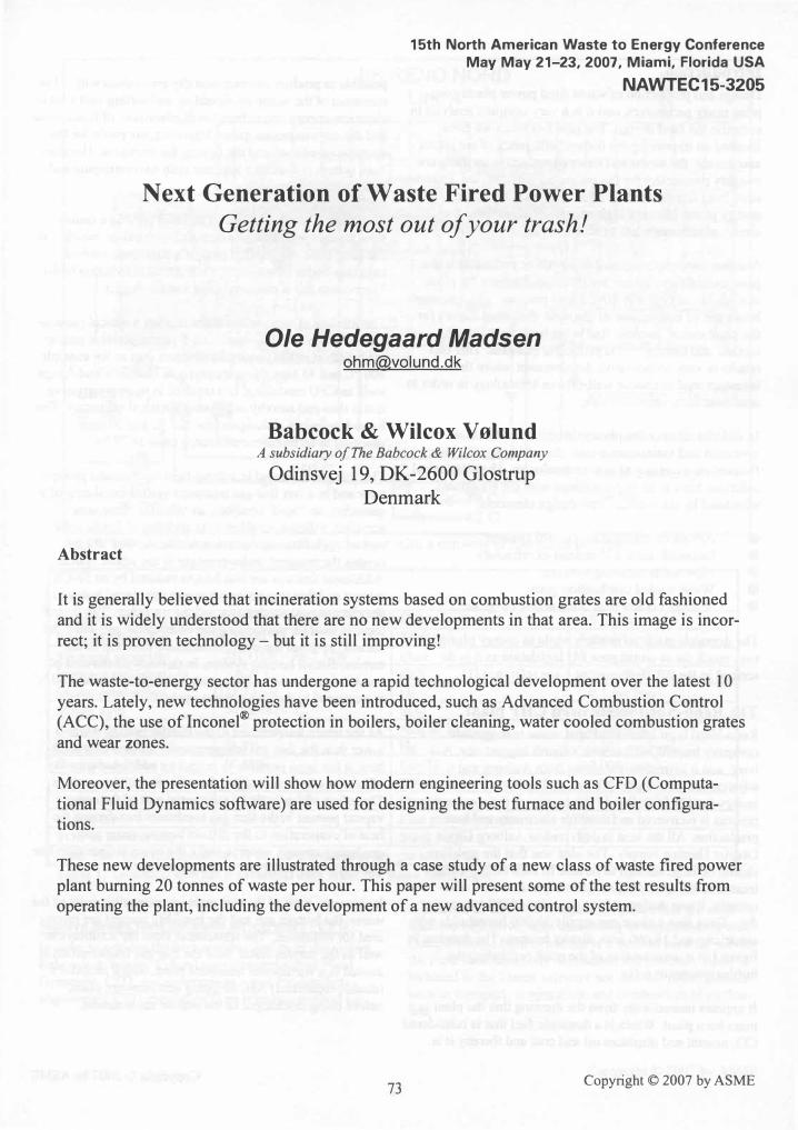
Reno-Nord is an inter-municipal waste management company located in Denmark's fourth biggest city, Aalborg, and it is treating the waste from Aalborg and 6 adjacent municipalities. It owns and operates a waste-toenergy facility in Aalborg. The energy of the combustion process is recovered and used for electricity and heat production. All the heat is delivered to Aalborg City's District Heating Supply. The idea was that the new line should be large enough to be able to bum all the waste treated in the area, 160,000 tonnes per annum. Consequently, it was designed for a capacity of 500 tonnes per day. Thus, line 4 alone can supply 30,000 households with electricity and 16,000 with district heating. The drawing in fIgure 1 is a cross section of the plant (excluding the turbine/generator set).
It appears immediately from the drawing that the plant is a mass bum plant. Waste is a domestic fuel that is considered CO2 neutral and displaces oil and coal and thereby it is
74
possible to produce environmentally green electricity. Pretreatment of the waste by shredding and sorting cost a lot of electrical energy and reduce the displacement of fossil fuels and the environmental gains. Moreover, the profIt for the operator is reduced and the tipping fee increases. The mass bum system is therefore superior both environmental and economical.
The waste is combusted on an inclined grate in a centreflow furnace with a large afterburning chamber, which - at the same time - is the fIrst pass of a three-pass vertical radiation boiler followed by a horizontal convection boiler. The bottom ash is removed via a wet de-slagger.
The lifetime of superheater tubes is often a critical parameter, and today the main trend is a 5 years operation guarantee based on rather conservative steam data as for example 400°C and 45 bars. New materials as Inconel® and design tools as CFD modelling, has resulted in more progressive steam data and thereby increasing electrical efficiency. The Reno Nord plant is designed for 425°C and 50 bars resulting in an electrical efficiency close to 27 %.
The flue gas is treated in a three-field electrostatic precipitator and in a wet flue gas treatment system consisting of a quencher, an 'acid' scrubber, an 'alkaline' limestone scrubber, a dioxin scrubber with addition of lignite coke and an agglofIltering venturi scrubber. A "wet" ID fan creates the required under-pressure in the whole system. Additional features are that NOx is reduced by an SNCR system and that two heat exchangers are placed between the electrostatic precipitator and the quencher. The first of these is used for pre-heating the combustion air, while the second pre-heats the steam condensate from the steam turbine/district heating system. In this way all the heat of combustion down to a flue gas temperature of around 90°C is recovered to the steam/water cycle.
As the return temperature of the district heating water is lower than the flue gas temperature in the fIrst two scrubbers, it has been possible to extract an additional quantity of heat in a heat exchanger placed in the dioxin scrubber. The effect of this is that a substantial part of the water vapour present in the flue gas condenses transferring the heat of evaporation to the district heating water and producing enough water to make the entire incineration line more than self-sufficient in process water.
In this way, both of the two main incombustible parts of the waste: the bottom ash and the humidity content are recovered for utilisation. The wastewater from the scrubbers as well as the surplus water from the flue gas condensation is treated in a wastewater treatment plant, which includes a (double/redundant) NH3 stripping and recovery plant, before being discharged to the marine environment.
Copyright © 2007 by ASME
lIS RENO NORD Line 4
Condensate, inlet 75' C 220'C
150'C Condensate, outlet 90' C
[EJ Heat exchanger Total air fan � Air fan
Figure 1. Waste fIred power plant Reno Nord unit 4 with a capacity of 500 tonne per day.
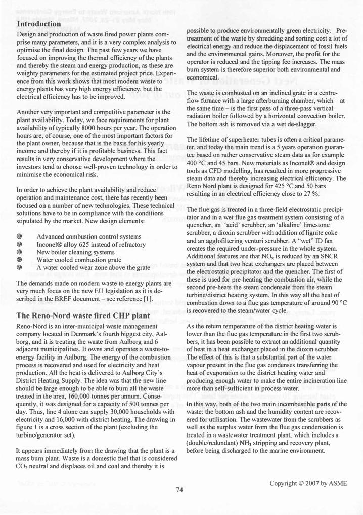
Technical and Environmental Data
Capacity 20 tIh CO < 5 mg/Nm3
Net calorific value 12 GJ/t TOC <l m�mj
Thermal capacity 240 GJIb = 66.7 MW Dust < 1 mg/NmJ
Furnace temperature > 850 °C HCl < 1 mg/NmJ
Steam production 22.2 kg/s HF < 0. 1 mg/Nm3
Steam data 50 bar/425 °C S02 < 10 mg/Nm3
Electricity production 17.9MW NOxas N02 150 mgjN'mJ Electrical efficiency 26.8% Hg < 0.003 mg/N'm' Heat production 47MW Cd+Tl < 0.000 1 mg/Nm3
Thermal efficiency 97% l: 9 metals < 0.009 mg/Nm3
Flue gas flow 1 10,000 Nm3 Ib Dioxins 0.013 Dg/NmJ Teq. Excess air -5.5%02 Flue gas temperature 180 °C TOC in bottom ash 0.3% Stack height 75 m Note: The reference condition for the air emissions isdfY gas at 1 1 % O2
Table 1. Techmcal and environmental data from the Reno Nord plant.
Modern design tools for waste incinerators - CFD
In order to achieve the best possible design of the system, Babcock & Wilcox V"lund uses Computational Fluid Dynamics, CFD, and programs as a tool for detailed engineering. CFD simulation is an effective method for
75
evaluation of different design alternatives that are otherwise too expensive, time consuming or impossible to test. Computational fluid dynamics is a method used for solving the fluid flow equations with numerical methods. Also included in the Fluent software are discrete phase models such as transport, evaporation, and combustion of particulate.
Copyright © 2007 by ASME

The chemically bound energy in the waste is released partly in the fuel layer and partly in the furnace room. Even though a certain surplus of primary air is led to the combustion process in the waste on the grate under normal conditions, a local gasification of the waste will take place. This is among other things due to the fact that the waste layer is very inhomogeneous, and some of the combustion air can penetrate through channels created in the waste layer. Furthermore, pyrolysis gases will be released in the ignition zone due to a fast heating up of the upper waste layer before the combustion begins.
These burnable gases flow up into the furnace room where they are mixed with surplus primary air from other parts of the grate and with secondary air. Thus, a pure gas phase combustion right above the fuel layer is created, whereby a relatively large part of the waste energy is released, typically 30% to 50% of the energy input - References [2]. Finally, some particles will "leave" the grate and burn in the furnace room and in the post combustion chamber.
The system, named VoluMix™, is designed on the basis of computational fluid dynamics (CFD) modelling - see figure 2. VoluMix™ is a special designed over fire air system and its advantages include:
• Good mixing and combustion conditions in the furnace - ignition
• Staged combustion makes it possible to reduce the formation of fuel NOx
• Avoidance of hot spots in the furnace and boiler which would speed up corrosion
• Obtaining turbulent conditions for optimum burnout - extreme low CO levels
• Uniform temperature and velocity distribution in the passes in order to maximize heat transfer and residence time
• Low excess air resulting in high overall thermal efficiency
Figure 2. VoluMix™ is a special designed over fire air system resulting in good mixing and uniform temperature in the boiler. The double rotating flows in the post combustion chamber prevent recirculation in the radiant drafts or emission of carbon monoxide.
Copyright © 2007 by ASME 76

10,0 -= Oxygen & Carbon Monoxide
=- 50,00 9,0 :: : 45,00 8,0 :: : 40,00 7,0 :: : 35,00 ....... n
� 0 � ........ s:: � QJ 5,0 25,00 lC en - ...... >. � x
0 4,0 :: w ......
3,0 :: - Oxygen (wet) : 15,00 2,0 :: -CO : 10,00 1,0 :: 0,0 -=; I I I I I I I I I I I I I r- 0,00
0 2 3 4 5 6 7 8 9 10 11 12 13 14 15 16 17 18 19 20 21 22 23 24 Time [h]
Figure 3. Process data from Reno Nord as function of time. The oxygen content in the flue gas is on wet basis.
As a result of this system, it is possible operate down to an excess air ratio corresponding to around 4Yz too 5 % O2 in the flue gas without problems with carbon monoxide and there was no need to consider flue gas recirculation. Thereby electrical energy for the fan is avoided and operating and maintains cost are minimized.
Combustion control
A new EU legislation for landfills will reduce and finally forbid the amount of burnable waste that goes to landfill. The consequence is more variation in the heating value of the waste going to combustion. Furthermore, there will be increased focus on reducing the operating cost in order to be competitive and reduce the cost per tonne burned waste. All in all, these tendencies will increase the demand for combustion control systems.
The standard DCS systems are fully capable of controlling the plant and maintain stable operation but in some cases it can be useful to expand the normal control concept by an ACC system - Advanced Combustion Control system. The main objectives by using ACC systems are: Improve process stability o Automatically handling of major steps or change of the
heating value - fuel flexibility o Fixed position of main combustion and burnout zone o Reduction of excess air and emissions o Increased thermal efficiency o Reduction in variation of process parameters as steam
flow, temperatures, CO etc. o Increased annual waste throughput
o Optimal quality of ashes through systematically controlled burnout
o Reducing operation cost o Less operation people on each working shift - even
unmanned in night time o Reduce maintenance cost and operational mistakes o Reduce consumables o Increased lifetime of boiler & refractory through a more
constant thermal exposure of the plant components, reduced stress on the turbine
o Increased availability
The combustion reaction rate is very difficult to determine as the controlling partial processes are heterogeneous solid gasification and combustion, and homogeneous gas phase combustion in and above the fuel layer. Generally, the processes between the oxygen in the combustion air and the solid waste are diffusion controlled and thereby relatively slow, whereas the gas phase combustion is controlled by temperature and concentrations, and the rate of reaction is relatively high. In practice, this means that the reaction rate of the whole process is mainly controlled by the mass flow of primary combustion air and its temperature.
Knowledge of all the above processes is very important in relation to design and operation of a waste combustion system. Some important design parameters to be considered are: Type of grate, excess air flow, primary and secondary air distribution, waste bed height, grate speed, etc.
77 Copyright © 2007 by ASME
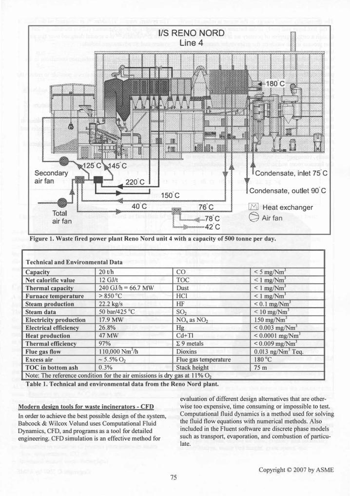
As previously mentioned, there is a strong connection between the burning rate and the amount of primary air, both the total amount and the distribution along the grate. As regards control and operation, the major difficulties appear to be:
• Adjustment of operating conditions to compensate for changes in the waste quality and quantity.
• The lack of measurement techniques available for rapid evaluation of the combustion processes in the fuel bed.
Symbols
t:[[[] IR thermograph
tCJ CCO Camera (RGB)
� Acuslic gas temperature
measurement
@ Temperature measurement ( __ f)
CD Temperature, primary air
@ Pressure drop over fuel bed
® Gas components (O"H20, CO mv.)
® Flame position and color
@ Mass flow sensor
® Grate speed
,.::===::::.;---·_ ..... ,10 Crane weight
0' Fuel level measurement
@ H,O-content, humidity measurement
® Temperature measurements
in cooling circuit
Simulator = combustion+ process model
Figure 4. Sensors, instruments and measurement techniques used in modern waste fired power plants in order to develop new advanced combustion control systems.
The second topic has been the aim of several research projects and development activities during the latest 10 years - References [3, 4 & 5]. Today, there are many possibilities - see figure 4, and combustion control system will typically be based on classic process measurements and new advanced sensors. The data can be used in model simulators that estimate new parameters as the waste heating value. In the following two examples will be given on these new systems.
Many have developed measurement and monitoring systems based on an IR camera, capable of providing a thermal mapping across the fuel bed. The thermal image is used to calculate mean temperatures for a number of locations across the grate corresponding to the individual primary air zones. The thermal image is evaluated to give an indirect indication of the intensity of the combustion on the grate.
The advantage of the camera measurement system is detailed information in 2-dimensions about the surface temperature of the fuel bed. The main weakness of this technique is the
78
interpretation of the data and influence of solid particles on the thermal image. Recording of high radiation in one area could be a result of a high concentration of burning particles and soot instead of a hot spot on the fuel bed. It is wellknown that in some parts of the fuel bed gasification is more pronounced than combustion. The thermal image cannot give information about the type of process going on in the fuel bed.
IR sensors and Neural network
The main objectives of our ACC system are to maintain a uniform flue gas temperature profile - thus reducing the size and number of high temperature regions and to control the primary combustion air distribution and ratio of primary to secondary combustion air flow. Furthermore, the system controls and adjusts the position of the main combustion zone to meet variations in the waste heating value. The system sensors are IR cameras and the signals are digitized and analyzed in a neural network based control system with feed forward signal to the standard control system.
Copyright © 2007 by ASME

The first operating ACC system in Denmark is installed at the L90 plant and has been in operation for more than 3 year. The L90 plant is a waste fired power plant burning a mixture of household and industrial waste (average heating value 10.6 MJ/kg) with a capacity of 600 tonne per day producing 18 MW electricity and 54 MW heat for district heating - with an overall thermal efficiency of 89 %.
The ACC system consists of a number of CCD cameras and a control unit built up around the neural network. The technology is described in detailed in reference [5].
The neural network part of the ACC system is open to all signals of the plant. The neural network will find coherences of the parameters and adjust the control accordingly, for example the secondary air vs. oxygen, secondary air vs. NOx, etc. The neural network is able to learn the behaviour of a plant by looking at the process parameters, and as a result the ACC system will be able to manage some of the operator's work.
Being in operation, the neural network generates remote set points to the energy controller, the grate velocity controller and the combustion air controllers. Each of these controllers' set points can be individually chosen to run at either a remote set point from the neural network or from a set point chosen by the operator. The ACC system will continuously adjust the primary air distribution, the primary and secondary air amount, the primary air temperature and the grate velocity in order to achieve a stable and good combustion and to ensure that the different combustion processes on the grate are correctly located.
The master set point for the production of the plant is the desired steam flow. The steam flow is thereby the parameter of main interest when evaluating the performance of the control system. The major [mdings were a reduction of 40 % in the scattering of the steam flow. The ACC system decreases both the variations of the steam flow and the maximum amplitude of the oscillations. Thus, the combustion process has been stabilized by means of relatively small set point corrections.
Fuel bed control
By measuring the pressure below the grates and by comparing this pressure with the pressure in the furnace, it is possible to determine the loss of pressure above each individual grate and grate layer. In a stable and even operational situation with constant fuel supply and - quality, a pressure increase will be an expression of an increase of the grate layer, and a pressure drop is an expression of a reduction of the grate layer. But the pressure drop also depends on the primary air flow, and this varies with the load. For determination of variations of the layer thickness on the grates, the pressure loss coefficient is a better measure, as this figure to a certain extent depends on the primary air flow and, with that, also on the load.
Reno Nord is equipped with pusher and 4 grates in two rows; in total 8 separate grate sections. Grate 1 is the drying and ignition grate, grates 2 and 3 are the main combustion grates,
79
and grate 4 is the burn out grate. The flame front is typically between the middle of grate 3 and the grate transition between grates 3 and 4.
Before the fuel bed control was introduced at Reno Nord, some of the oscillations of the energy production were due to lack of fuel. The course was as follows: The pressure below grate 1 falls, followed by a pressure drop above grate 2. Then the oxygen percentage increases, and the output falls. More fuel is added, and subsequently the output shows an over swing. Le. first there is an under swing due to lack of fuel, followed by an over swing due to an overreaction from the energy and oxygen control.
Pressure loss coefficient �
Figure 5. illustration of coefficient of resistance control.
The idea of fuel bed control is that the correct amount of waste is available on the main combustion grates - in this case grates 2 and 3. In this way under swing - and the successive over swing - is reduced (or completely avoided) due to lack of fuel. The coefficient is an expression of the layer thickness.
The calculated figure is part of a model based control system. This figure is used as a process value in a P-regulator adjusting the velocity of pusher and grate 1.
If the pressure loss coefficient on grate 2 is reduced, it indicates that either the layer thickness is reduced (by a constant fuel type), or that the fuel has become lighter. In both cases the fuel flow to grate 2 has to be increased. This is done by increasing the velocity of pusher and grate 1. Correspondingly, if the coefficient of resistance on grate 2 is increased, the velocity of pusher and grate 1 is reduced. In this way, the coefficient of resistance of grate 2 can be controlled. The control principle is illustrated in Figure 5.
Copyright © 2007 by ASME
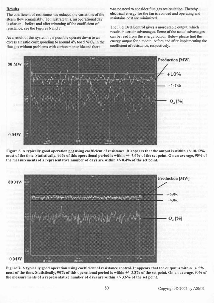
Results
The coefficient of resistance has reduced the variations of the steam flow remarkably. To illustrate this, an operational day is chosen - before and after trimming of the coefficient of resistance, see the Figures 6 and 7.
As a result of this system, it is possible operate down to an excess air ratio corresponding to around 4Y:z too 5 % O2 in the flue gas without problems with carbon monoxide and there
80MW
OMW
was no need to consider flue gas recirculation. Thereby electrical energy for the fan is avoided and operating and maintains cost are minimized.
The Fuel Bed Control gives a more stable output, which results in certain advantages. Some of the actual advantages can be read from the energy output. Below please find the energy output for a month, before and after implementing the coefficient of resistance, respectively.
-10%
°2 [%]
Figure 6. A typically good operation not using coefficient of resistance. It appears that the output is within +/- 10-12% most of the time. Statistically, 90% of this operational period is within +/- 5.6% of the set point. On an average, 90% of the measurements of a representative number of days are within +/- 8.4% of the set point.
80 MW '
OMW
+5%
-5%
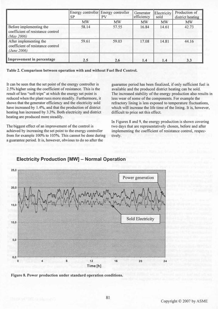
Figure 7. A typically good operation using coefficient of resistance control. It appears that the output is within +/- 5% most of the time. Statistically, 90% of this operational period is within +/- 3.3% of the set point. On an average, 90% of the measurements of a representative number of days are within +/- 3.6% of the set point.
80 Copyright © 2007 by ASME
Energy controller Energy controller Generator Electricity Production of SP PV efficiency sold district heatinA
MW MW MW MW MW Before implementing the 58.14 57.55 16.84 14.61 42.73 coefficient of resistance control (May 2006)
After implementing the 59.61 59.03 17.08 14.81 44.16 coefficient of resistance control (June 2006)
Improvement in percentage 2.5 2.6 1.4 1.4 3.3
Table 2. Comparison between operation with and without Fuel Bed Control.
It can be seen that the set point of the energy controller is 2.5% higher using the coefficient of resistance. This is the result of less "soft trips" at which the energy set point is reduced when the plant runs more steadily. Furthermore, it shows that the generator efficiency and the electricity sold have increased by 1.4%, and that the production of district heating has increased by 3.3%. Both electricity and district heating are produced more steadily.
The biggest effect of an improvement of the control is achieved by increasing the set point to the energy controller from for example 100% to 105%. This cannot be done during a guarantee period. It is, however, obvious to do so after the
guarantee period has been finalized, if only sufficient fuel is available and the produced district heating can be sold. The increased stability of the energy production also results in less wear of some of the components. For example the refractory lining is less exposed to temperature fluctuations, which will increase the life time of the lining. It is, however, difficult to price set this effect.
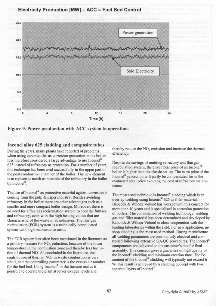
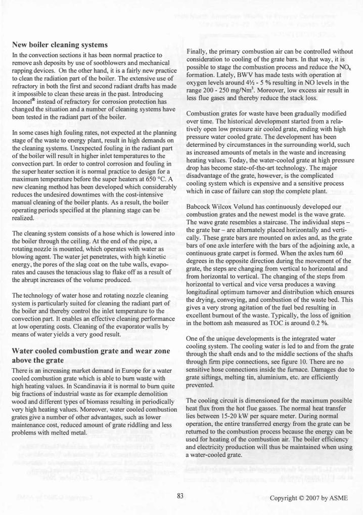
In Figures 8 and 9, the energy production is shown covering two days that are representatively chosen, before and after implementing the coefficient of resistance control, respectively.
Electricity Production [MW] - Normal Operation 25,0 ,..--------------�----.....,.---....,.,.'""""'''''''''..,.-------_...,
Power generation
20,0+--.-�r------_:__-___:r_--------------._._-_\_;
15,0
10,0
5,0+---------�---------�-�------------_1
0,0+-----�---��---�------------------_4 o 4 8 12
Time [h] 16
Figure 8. Power production under standard operation conditions.
81
20 24
Copyright © 2007 by ASME
Electricity Production [MW] - ACC = Fuel Bed Control
25.0 -'--�--------__ ------------------,
Power generation
20.oL--------------��"........--�========;�-_1
Sold Electricity 10.0 ----- -------------------L _______ ....J"'-.
5.0+----�-----------------...-,,---�
0.0 -I-----..,.---�-....--...--..---.--------,....�-....-----.-----�24 o 4 8 12 16 20 Time [h)
Figure 9. Power production with ACe system in operation.
Inconel alloy 625 cladding and composite tubes
During the years, many plants have reported of problems when using ceramic tiles as corrosion protection in the boiler. It is therefore considered a large advantage to use Inconel®
625 instead of refractory as protection. For a number of years, this technique has been used successfully in the upper part of the post combustion chamber of the boiler. The ne
.w eleme�t
is to replace as much as possible of the refractory m the boller by Inconel®.
The use of Inconel® as protective material against corrosion is coming from the pulp & paper industry. Besides avoiding refractory in the boiler there are other advantages such as � smaller and more compact boiler design. Moreover, there IS no need for a flue gas recirculation system to cool the furnace and refractory, even with the high heating values that are characteristic of the waste in Scandinavia. The flue gas recirculation (FGR) system is a technically complicated system with high maintenance costs.
The FGR system has often been mentioned in the literature as a primary measure for NOx reduction, because of the lower temperature in the combustion zone and thereby less formation of thermal NO. As concluded in the literature, the contribution of thermal NOx in waste combustion is very small and the controlling parameter is the excess air number ,
® furn ak ' for the fuel bed. Using Inconel in the ace m es It possible to operate the plant at lower oxygen levels and
82
thereby reduce the NOx emission and increase the thermal efficiency.
Despite the savings of omitting refractory and flue gas recirculation system, the direct total price of an Inconel®
boiler is higher than the classic set-up. The extra price of the Inconel® protection will partly be compensated for in �e evaluated plant price avoiding the cost of refractory mamtenance.
The most used technique is Inconel® cladding which is an overlay welding using Inconel® 625 as filler material. Babcock & Wilcox V"lund has worked with this concept for more than 10 years and is specialised in corrosion protec�ion of boilers. The combination of welding technology, welding gas and filler material has been determined �d de�eloped by Babcock & Wilcox V"lund in close cooperation Wlth the leading laboratories within the field. For new application, inshop cladding is the most used method. During manufacture all welding parameters are continuously checked and controlled following extensive QNQC procedures. The Inconel®
components are delivered to the customer's si�e for f�al assembly. This concept gives a guarantee of high qualIty of the Inconel® cladding and minimum erection time. The Fecontent of the Inconel® cladding will typically not exceed 6 %. this result is achieved by a cladding concept with two ,
® separate layers of Inc one I .
Copyright © 2007 by ASME
New boiler cleaning systems
In the convection sections it has been normal practice to remove ash deposits by use of sootblowers and mechanical rapping devices. On the other hand, it is a fairly new practice to clean the radiation part of the boiler. The extensive use of refractory in both the first and second radiant drafts has made it impossible to clean these areas in the past. Introducing Inconel@ instead of refractory for corrosion protection has changed the situation and a number of cleaning systems have been tested in the radiant part of the boiler.
In some cases high fouling rates, not expected at the planning stage of the waste to energy plant, result in high demands on the cleaning systems. Unexpected fouling in the radiant part of the boiler will result in higher inlet temperatures to the convection part. In order to control corrosion and fouling in the super heater section it is normal practice to design for a maximum temperature before the super heaters at 650 CC. A new cleaning method has been developed which considerably reduces the undesired downtimes with the cost-intensive manual cleaning of the boiler plants. As a result, the boiler operating periods specified at the planning stage can be realized.
The cleaning system consists of a hose which is lowered into the boiler through the ceiling. At the end of the pipe, a rotating nozzle is mounted, which operates with water as blowing agent. The water jet penetrates, with high kinetic energy, the pores of the slag coat on the tube walls, evaporates and causes the tenacious slag to flake off as a result of the abrupt increases of the volume produced.
The technology of water hose and rotating nozzle cleaning system is particularly suited for cleaning the radiant part of the boiler and thereby control the inlet temperature to the convection part. It enables an effective cleaning performance at low operating costs. Cleaning of the evaporator walls by means of water yields a very good result.
Water cooled combustion grate and wear zone
above the grate
There is an increasing market demand in Europe for a water cooled combustion grate which is able to burn waste with high heating values. In Scandinavia it is normal to burn quite big fractions of industrial waste as for example demolition wood and different types of biomass resulting in periodically very high heating values. Moreover, water cooled combustion grates give a number of other advantages, such as lower maintenance cost, reduced amount of grate riddling and less problems with melted metal.
83
Finally, the primary combustion air can be controlled without consideration to cooling of the grate bars. In that way, it is possible to stage the combustion process and reduce the NO formation. Lately, BWV has made tests with operation at x oxygen levels around 4Y2 - 5 % resulting in NO levels in the range 200 - 250 mglNm3• Moreover, low excess air result in less flue gases and thereby reduce the stack loss.
Combustion grates for waste have been gradually modified over time. The historical development started from a relatively open low pressure air cooled grate, ending with high pressure water cooled grate. The development has been de�ermined by circumstances in the surrounding world, such as �creased amounts of metals in the waste and increasing heatmg values. Today, the water-cooled grate at high pressure �op has become state-of-the-art technology. The major disadvantage of the grate, however, is the complicated cooling system which is expensive and a sensitive process which in case of failure can stop the complete plant.
Babcock Wilcox V"lund has continuously developed our combustion grates and the newest model is the wave grate. The wave grate resembles a staircase. The individual steps -the grate bar - are alternately placed horizontally and vertically. These grate bars are mounted on axles and, as the grate bars
.of one axle interfere with the bars of the adjoining axle, a
contmuous grate carpet is formed. When the axles turn 60 degrees in the opposite direction during the movement of the grate, the steps are changing from vertical to horizontal and from horizontal to vertical. The changing of the steps from horizontal to vertical and vice versa produces a waving longitudinal optimum turnover and distribution which ensures the drying, conveying, and combustion of the waste bed. This gives a very strong agitation of the fuel bed resulting in
�xcellent burnout of the waste. Typically, the loss of ignition m the bottom ash measured as TOC is around 0.2 %.
One of the unique developments is the integrated water cooling system. The cooling water is led to and from the grate through the shaft ends and to the middle sections of the shafts through finn pipe connections, see figure 10. There are no sensitive hose connections inside the furnace. Damages due to grate siftings, melting tin, aluminium, etc. are efficiently prevented.
The cooling circuit is dimensioned for the maximum possible heat flux from the hot flue gasses. The normal heat transfer lies between 15-20 kW per square meter. During normal operation, the entire transferred energy from the grate can be returned to t�e combustion process because the energy can be used for heating of the combustion air. The boiler efficiency and electricity production will thus be maintained when using a water-cooled grate.
Copyright © 2007 by ASME

Figure 10. The new water-cooled Wave grate with integrated cooling system in the axle.
A water cooled wear zone above the grate
It is a common problem that clinker is building up just above the burning waste layer. The main reason is a high surface temperature at the refractory wear zone causing the ash to stick to the wall. In severe cases, the clinker will disturb the combustion process and the plant has to be taken out of operation for cleaning. This can be avoided by using a low temperature wear zone. The new wear zone is made by a number of heavy steel tubes cooled by a closed water cycle, and the absorbed energy is led back into the boiler by preheating the primary air. In this case the burning fuel layer is gliding along the cool steel surface without any slagging problems - see figure 11. The water cooled wear zone can also be an integrated part of the steam boiler but then the surface has to bee protected with Inconel@. In figure 11 the water cooled wear zone is the red tubes and the boiler membrane wall is the vertical tubes. The boiler tubes are Inconel@ covered and the wear zone is also acting as the sealing between the hanging boiler and the combustion grate. The sealing is necessary because of the thermal expansion of the boiler during heat up and cooling down.
Figure 11. Photo of the water cooled wear zone (red tubes) at the FTG plant Sweden.
84
Conclusions
Waste fired power plants are an important part of the European waste management system and the new European Commission legislation have influenced the design and planning of new plants. Moreover, new trends in the common market as harmonisation and liberalisation will create even more focus on costs. In order to comply with these demands, new technical developments are focused on improving the plant availability and reducing operating and maintenance cost.
Waste fired power plants are based on proven technology and the technology is still improving.
References
1. European Integrated Pollution Prevention and Control Bureau; Reference Document on the Best Available Techniques for Waste Incineration, July 2005, Sevilla, Spain http://eippcb.jrc.es/pagesIBActivities.cfrn
2. Rogers J.E.L., Sarofim A.F. and Howard I.B.; Effect of underfrre air rate on a burning simulated refuse bed, Proceedings 1972 National Incinerator Conference, New York.
3. Schiller F., Rampp F., Martin I., Wolfrum I.; TACCOS - A Thermography Assisted Combustion Controlled System for Waste Incinerators, Combustion & Flame 99, p 431-439, 1994.
4. Hiller W., Neukirchen B., Wintrich F.; Uberpriifung einer Miillfeuerung mit innovativer Messtechnik -auch ein Weg zur Simulationskontrolle, Milll und Abfall, 12, 1996.
5. Ole Hedegaard Madsen and Jacob Munch Jensen; Practical test of ACC systems for Waste to Energy plants, 3rd International Conference on Combustion, In-cinerationlPyrolysis and Emission Control, Hangzhau, China, 21- 23 October 2004.
Copyright © 2007 by ASME