Embed Size (px)
Citation preview

Next Generation Integrated Power Systems (NGIPS) for the Future Fleet
United States Naval AcademyMarch 30, 2009
CAPT Norbert DoerryCAPT Norbert DoerryTechnical Director, Future Concepts and Surface Ship Design
Naval Sea Systems Command [email protected]
March 2009 Approved for Public Release CAPT Doerry
1

Agenda
• Vision• NGIPS Technology Development Roadmap• NGIPS Architectures• NGIPS Design Opportunities• Institutionalizing the Electric Warshipg p
March 2009 Approved for Public Release CAPT Doerry
2

Electric Warship VisionOrganic Surveillance DroneHigh Altitude Beam Power to Aircraft
Electromagnetic GunElectromagnetic GunMore than 10 MJ on
Minimal Handling - No RefuelingHigh Powered Sensor
Combination Sensor and Weapon
NO ENERGETICS NO ENERGETICS ABOARD SHIP!ABOARD SHIP!
More than 10 MJ on TargetMegawatt Range
High Energy Laser
WeaponHigh Powered MicrowaveHigh Powered Laser
Enhanced Self DefensePrecision Engagement
Integrated Power SystemAffordable Power for Weapons and g g
No Collateral DamageMegawatt Class Laser
PropulsionPower Dense, Fuel Efficient PropulsionReduced Signatures
All Electric AuxiliariesNo HydraulicsNo HP Gas SystemsReduced Signatures
Power Conversion FlexibilityNo HP Gas SystemsReduced Sailor Workload
March 2009 Approved for Public Release CAPT Doerry
3
NGIPS Technology Development Roadmap
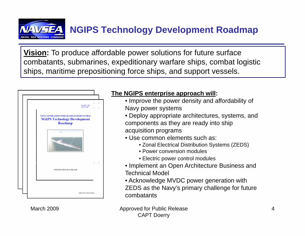
Vision: To produce affordable power solutions for future surface combatants, submarines, expeditionary warfare ships, combat logistic ships, maritime prepositioning force ships, and support vessels.ships, maritime prepositioning force ships, and support vessels.
The NGIPS enterprise approach will:• Improve the power density and affordability of p p y yNavy power systems• Deploy appropriate architectures, systems, and components as they are ready into ship acquisition programsq p g• Use common elements such as:
• Zonal Electrical Distribution Systems (ZEDS)• Power conversion modules• Electric power control modules
• Implement an Open Architecture Business and Technical Model• Acknowledge MVDC power generation with ZEDS as the Navy’s primary challenge for future
March 2009 Approved for Public Release CAPT Doerry
4
combatants

NGIPS Technology Development Roadmapsi
tyow
er D
en
Hi h F
Medium Voltage Direct Current (MVDC) 6 kVDC
• Reduced power conversionEli i t t fPo High Frequency
Alternating Current (HFAC) 4-13.8kVAC200-400 Hz
•Power-dense generation•Power-dense transformers•Conventional protectionMedium Voltage AC
• Eliminate transformers• Advanced reconfiguration
Now Near Future
DDG 1000
•Conventional protectiongPower Generation (MVAC) 4-13.8 kVAC60 Hz
March 2009 Approved for Public Release CAPT Doerry
5
Now Near Future“Directing the Future of Ship’s Power”“Directing the Future of Ship’s Power”

IPS Architecture
• Integrated Power– Propulsion and Ship Service Loads provided power from same p p p p
prime movers
• Zonal DistributionLongitudinal Distribution buses connect prime movers to loads– Longitudinal Distribution buses connect prime movers to loads via zonal distribution nodes (switchboards or load centers).
Approved for Public Release CAPT Doerry
6March 2009

Integrated Power System (IPS)
IPS consists of an architecture and a set of modules which together provide the basis for designing, procuring, and g g, p g,supporting marine power systems applicable over a broad range of ship types:
– Power Generation Module (PGM)Power Generation Module (PGM)– Propulsion Motor Module (PMM)– Power Distribution Module (PDM)– Power Conversion Module (PCM)– Power Control (PCON)– Power Control (PCON)– Energy Storage Module (ESM)– Load (PLM)
Approved for Public Release CAPT Doerry
7March 2009
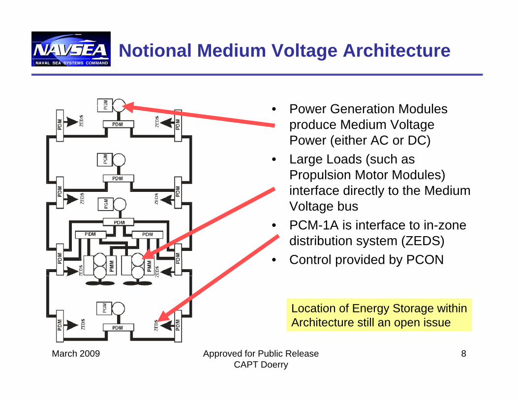
Notional Medium Voltage Architecture
• Power Generation Modules produce Medium Voltageproduce Medium Voltage Power (either AC or DC)
• Large Loads (such as Propulsion Motor Modules)Propulsion Motor Modules) interface directly to the Medium Voltage bus
• PCM 1A is interface to in zone• PCM-1A is interface to in-zone distribution system (ZEDS)
• Control provided by PCON
Location of Energy Storage withinArchitecture still an open issue
March 2009 Approved for Public Release CAPT Doerry
8
Architecture still an open issue

Notional In-Zone Architecture
• PCM-1A– Protect the longitudinal bus from
in-zone faults – Convert the power from the
longitudinal bus to a voltage and frequency that PCM-2A can use
– Provide loads with the type of power they need with the requisitepower they need with the requisite survivability and quality of service
• PCM-2A– Provide loads with the type of
power they need with the requisite VAC
)
load
load load
VAC
)
p y qsurvivability and quality of service
– IPNC (MIL-PRF-32272) can serve as a model
• Controllable Bus Transfer (CBT)Provide two paths of power to
PCM
-1AMVAC
HFACMVDC
or1000 VDC
MVACHFACMVDC
or1000 VDC
PDM
(450
load
Emergency Loadvia CBT
PDM
(600
VD
C)
PDM
(450
PCM
-1A
PDM
(600
VD
C)
load
load load
Emergency Loadand un-interuptible
load v ia auctioneer ing diodes – Provide two paths of power to loads that require compartment level survivability
Location of Energy Storage within
via PCM-4 via PCM-4
loadload
Un-interruptibleLoad Un-interruptible
Load
PCM-2A
March 2009 Approved for Public Release CAPT Doerry
9
gy gArchitecture still an open issueVariable Speed
Variab le Voltage Special Frequency
Load
load

NGIPS Design Opportunities
• Support High Power Mission Systemsy
• Reduce Number of Prime Movers
• Improve System Efficiency• Provide General Arrangements
FlexibilityFlexibility• Improve Ship Producibility• Facilitate Fuel Cell Integrationg• Support Zonal Survivability• Improve Quality of Service
March 2009 Approved for Public Release CAPT Doerry
10

Support High Power Mission Systems
DeployedMission
Capability2010 2016 2020+2015+
Increasing Power Demands20142012
WeaponSystem
DevelopmentTRL=6 Active
Denial System
30 MW1 MW 10 MW0.4 MW 2 MW1 MW
WeaponDevelopment
TRL=4/5
System
Solid State Laser System
Laser GuidedEnergy
FemtosecondLaser System
TechnologyDevelopment
TRL=3/4 Power Demands per MountMultiple Mounts per ship
Power Demands per MountMultiple Mounts per ship
Free Electron Laser System
Electro-Magnetic Launch
Rail Gun
Energy
Sensor and Weapons Power Demands willRival Propulsion Power DemandsSensor and Weapons Power Demands willRival Propulsion Power Demands
March 2009 Approved for Public Release CAPT Doerry
11

Reduce Number of Prime Movers
Ship’s Power Propulsion
TraditionalGEN
GEN
PowerConversion
andDi t ib ti
ReductionGear
Distribution
ReductionGear
Electric Drive
GEN
GEN
PowerConversion
andDistributionDrive
with Integrated
GEN
GEN
MtrMD
MtrMD
Distribution
March 2009 Approved for Public Release CAPT Doerry
12
Power GEN

Improve System Efficiency
• A generator, motor drive and motor will generally be less efficient than a reduction
Mechanical Drive
Electric Drive
Gas Turbine 30% 35%
Reduction Gear 99%
gear ….• But electric drive enables the
prime mover and propulsor
Generator 96%
Drive 95%
Motor 98%
to be more efficient, as well as reducing drag.
Propeller 70% 75%
Relative Drag Coefficient 100% 97%
Total 21% 24%
Ratio 116%
Representative values: not universally trueTRADE TRANSMISSION EFFICIENCY TO REDUCE DRAG TRADE TRANSMISSION EFFICIENCY TO REDUCE DRAG
AND IMPROVE PRIME MOVER AND PROPELLER EFFICIENCYAND IMPROVE PRIME MOVER AND PROPELLER EFFICIENCYMarch 2009 Approved for Public Release
CAPT Doerry13

Improve System Efficiency:Contra-Rotating Propellers
• Increased Efficiencyy– Recover Swirl Flow– 10 – 15% improvement
R i i l b i f• Requires special bearings for inner shaft if using common shaft line
Anders Backlund and Jukka Kuuskoski,
“The Contra Rotating Propeller (CRP) Concept with a Podded Drive”
• Recent examples feature Pod for aft propeller
http://www.mhi.co.jp/ship/english/htm/crp01.htm
March 2009 Approved for Public Release CAPT Doerry
14

General Arrangements FlexibilityImprove Ship Producibility
• Vertical Stacking of Propulsion Components Di l M h i l S tPropulsion Components
• Pods• Athwart ship Engine
M ti
Diesel Mechanical System
Mounting• Horizontal Engine
FoundationE i i
Propulsion / Elec tri cal PowerMachinery Space
• Engines in Superstructure
• Distributed Propulsion Integrated Power System
Intakes/Uptakes
Zones Without Propulsi on / Electr ical Power Spaces
Shaft Lin e
• Small Engineering Spaces
12APR94G.CDRNH D: S EA 03R 2Rev 1 28 MAR 95
March 2009 Approved for Public Release CAPT Doerry
15

Facilitate Fuel Cell Integration
• Many Advantages– Highly Efficient (35-60%)– Highly Efficient (35-60%)– No Dedicated intakes-
uptakes; use ventilation• Challengesg
– Reforming Fuel into Hydrogen – Onboard Chemical Plant.Eliminating Sulfur from– Eliminating Sulfur from fuels.
– Slow Dynamic Response –Requires Energy storage to b l ti dbalance generation and load
– Slow Startup – Best used for base-loads
March 2009 Approved for Public Release CAPT Doerry
16

Zonal Survivability• Zonal Survivability
– Zonal Survivability is the ability of the distributed system, when experiencing internal faults due to damage or equipment failure confined to adjacent g q p jzones, to ensure loads in undamaged zones do not experience an interruption in service or commodity parameters outside of normal parameters
• Sometimes only applied to “Vital Loads”• Compartment Survivability
– Even though a zone is damaged, some important loads within the damaged zone may survive. For critical non-redundant mission system equipment and y q ploads supporting in-zone damage control efforts, an increase level of survivability beyond zonal survivability is warranted.
– For these loads, two sources of power should be id d h th t if th l d i t d t iprovided, such that if the load is expected to survive,
at least one of the sources of power should also be expected to survive.
SURVIVABILITY DEALS WITH PREVENTING FAULT PROPOGATIONSURVIVABILITY DEALS WITH PREVENTING FAULT PROPOGATION
March 2009 Approved for Public Release CAPT Doerry
17
AND WITH RESTORATION OF SERVICE UNDER DAMAGE CONDITIONSAND WITH RESTORATION OF SERVICE UNDER DAMAGE CONDITIONS
Quality of Service
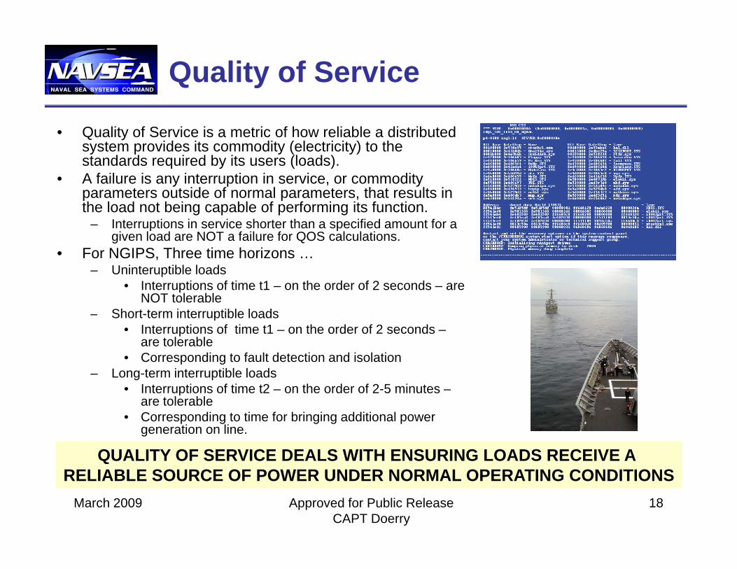
• Quality of Service is a metric of how reliable a distributed system provides its commodity (electricity) to the standards required by its users (loads).
• A failure is any interruption in service or commodity• A failure is any interruption in service, or commodity parameters outside of normal parameters, that results in the load not being capable of performing its function.
– Interruptions in service shorter than a specified amount for a given load are NOT a failure for QOS calculations.
F NGIPS Th ti h i• For NGIPS, Three time horizons …– Uninteruptible loads
• Interruptions of time t1 – on the order of 2 seconds – are NOT tolerable
– Short-term interruptible loadsp• Interruptions of time t1 – on the order of 2 seconds –
are tolerable• Corresponding to fault detection and isolation
– Long-term interruptible loads• Interruptions of time t2 – on the order of 2-5 minutes –Interruptions of time t2 on the order of 2 5 minutes
are tolerable• Corresponding to time for bringing additional power
generation on line.
QUALITY OF SERVICE DEALS WITH ENSURING LOADS RECEIVE A QUALITY OF SERVICE DEALS WITH ENSURING LOADS RECEIVE A
March 2009 Approved for Public Release CAPT Doerry
18
RELIABLE SOURCE OF POWER UNDER NORMAL OPERATING CONDITIONSRELIABLE SOURCE OF POWER UNDER NORMAL OPERATING CONDITIONS

Institutionalizing the Electric Warship
Early TechnologyDemonstration
Historic Focus ofEl t i W hiDemonstration
Incorporation intoProduction Units
Standardization of
Electric WarshipEfforts
Standardization of Architecture and Interfaces
Standardization ofD i P
NGIPSDesign Process
Integration into Design Tools
is addressingall aspects ofInstitutionalizing
Part of Engineering
Full Implementationin Standards and Specifications
gthe Electric Warship
g gSchool Curriculum
March 2009 Approved for Public Release CAPT Doerry
19

Standards & Specifications
• Naval Vessel Rules– Includes provisions for IPS– Updated AnnuallyUpdated Annually
• MIL-STD-1399 sections 300B and 680– Updated/created in 2008
• MIL-PRF-32272 IPNCMIL PRF 32272 IPNC– Model for PCM-2A issued in 2008
• IEEE Standards– IEEE Std 45 Electrical Installations on
ships – being extensively revised.– IEEE Std 1662 Power Electronics on Ships– P1676 Control Architecture
P1709 MVDC Power on Ships– P1709 MVDC Power on Ships– P1713 Electrical Shore-to-ship
Connections• NSRP Ship Production Panel on Electrical p
TechnologiesMarch 2009 Approved for Public Release
CAPT Doerry20

Summary
• Vision• NGIPS Technology
Development Roadmap• NGIPS Architectures• NGIPS Design Opportunitiesg pp• Institutionalizing the Electric
Warship
QUESTIONS?March 2009 Approved for Public Release
CAPT Doerry21