Embed Size (px)
Citation preview

Next generation energy simulation tools:Coupling 3D sketching with energy simulation tools
Ioannis Rizos MEng
A thesis submitted for the Degree:MSc in
Energy Systems and the Environment
Energy System Research UnitDepartment of Mechanical Engineering
University of StrathclydeSeptember 2007

COPYRIGHT DECLARATIONThe copyright of this thesis belongs to the Author under the terms of the United Kingdom
Copyright Acts as qualified by the University of Strathclyde Regulation 3.49. Dueacknowledgement must always be made of the use of any material contained in, or derived
from, this thesis.

Acknowledgements
Firstly I would like to thank the persons behind the implementation of “Demeter”, Malcolm Murray, David MacIver for their valuable contribution to the development of a prototype.
A special thanks to and Dr. Neil Finlayson, Donald Macritchie and all the people in GreenSpace research and UHI college for giving me the opportunity to work on something I always wanted as well as making me feel the hospitality of people in the Isle of Lewis
I am very grateful to my supervisor, Dr Paul Strachan for the valuable feedback given, teaching me how to be critical with my work, and the opportunity to present my work to Scientists I respect among ESRU.
Last but not least, a great thank you to my Parents, Dimitrios and Paraskevi, for supporting me throughout my academic education and Evi for being who she is.

Abstract
This dissertation primarily deals with investigating the barriers to the adoption of simulation
into the conceptual design stage. In this stage, the most important decisions that determine the
future of a building project are taken, and the 70% to 80% of capital resources are committed. An in
depth analysis to the conceptual designer's needs and priorities is conducted, to identify which are
the primary drivers for introducing simulation into the conceptual design stage.
Sketches produced in the conceptual design stage, are driven by the response of the designer
to a parameter optimisation procedure. These parameters include building functionality, aesthetics,
costs and lately, energy and environmental performance. However, with regards to the later, the
primary need of the designer is to ensure that a particular design proposal will not have to be “sent
back” for revision in order to conform with building regulations. Thus, strategic information should
be provided in order to guide the designer on issues such as orientation, glazing area, thermal mass,
internal daylight optimisation, maximisation of sunlight in outdoor recreation areas, costs, aesthetic
impact, functionality, etc.
Many design guidelines and rules of thumb have been developed to assist the Conceptual
designer in early design decisions. However, these design guidelines cannot provide decision
support based on a quantitative analysis, with regards to the particular project they are applied to.
Simulation should be applied at the conceptual design stage to provide the designer with the
decision support needed to ensure that the building will perform as required
There is a variety of CAD-sketching tools available to the Conceptual designer. However,
there is limited integration of these tools with state of the art simulation tools. In addition, there is a
paucity of information available regarding some aspects of the building, which create difficulties
and uncertainties about the application of simulation into the conceptual design process
A method that allows a non simulation expert to perform a simulation exercise and get
strategic design decision support is proposed in this dissertation. This method is based on three key
parameters:
➔ 3D CAD-Sketching integration
➔ Ease of use
➔ interoperability among different purpose energy simulation software
Two general tools are identified in this process – a 3D sketching tool and an energy
simulation tool. The selection of these tools was based on their ease of use and their popularity
among conceptual designers. However, in order to link the sketching tool with simulation tool, a
bespoke tool (plug-in) to the sketching environment has been developed.

The specifications of the specifications of the bespoken tool were defined through the use of
the Data Mining System (DMiS) and the data management system (DMaS). This dissociation was
made so that the development team and future developers can decompose what information is
entering the system (mining) and what is processed by the system (management). The general
concept behind the development of this plug-in was user functionality. Thus the majority of the
processes are automated while a few require some level of user interaction.
The central concept in the development of the interface of the plug-in is to enable a non
expert in building energy modelling to define certain properties of a simulation model. Hence, a
considerable amount of effort was made to develop a “user objectives” model and a “user
interaction” diagram. These were used to design a user friendly interface. The specifications of the
interface are presented in an activity diagram where both automated and semi-automated processes
are included.
The interface consists of several “modules”. The concept of modules was introduced in
order to help the user to understand the philosophy behind the tool. Four modules were
implemented in the GUI: The “Space definition module”, the “Surface and Openings definition
module”, the “Building information module” and the “Green Building Studio or gbXML file export
module”. In addition, the concept of a cube GUI was introduced. The “Cube interface” enables each
side of the cube to represent a different module.

Table of contents
Chapter 1: Introduction
1.1 Chapter structure ................................................................................................................................1
1.2 The evolution of buildings: Energy and Environmental considerations.............................................2
1.3 Building regulations ...........................................................................................................................4
1.4 Building design....................................................................................................................................6
1.4.1 Introduction................................................................................................................................6
1.4.2 Stakeholders...............................................................................................................................6
1.4.3 Building design stages: Analysis and discussion.......................................................................7
1.5 Simulation supported design process...................................................................................................9
1.5.1 Energy and Environmental Design Decision Support Systems.................................................9
1.5.2 Discussion upon EEDDSS........................................................................................................10
1.6 The application of simulation in the building design process.............................................................11
1.6.1 introduction...............................................................................................................................11
1.6.2 Initiatives and drivers to advance the use of simulation in the building design process..........11
1.6.3 New and perceiving barriers.....................................................................................................13
1.6.4 The likelihood of a change........................................................................................................14
1.7 Building simulation tools...................................................................................................................15
1.7.1 Software tool taxonomy............................................................................................................15
1.7.2 The evolution of building energy simulation tools...................................................................16
1.7.3 Simulation languages and simulators........................................................................................17
1.7.4 Front end interfaces bespoken for certain design stages...........................................................17
1.7.5 Overview of easy to use building design tools..........................................................................18
1.8 Closing remarks...................................................................................................................................20
2 Chapter 2: Conceptual design stage and Simulation
2.1 Introduction..........................................................................................................................................23
2.2 What is the conceptual design stage.....................................................................................................23
2.3 Conceptual designer's needs................................................................................................................ 24
2.3.1 Introduction................................................................................................................................24
2.3.2 Discussion..................................................................................................................................25
2.3.3 Needs and priorities....................................................................................................................25
2.4 The role of modelling in the conceptual Design stage.........................................................................26
2.5 Barriers to the adoption of simulation into the conceptual design stage..............................................27
2.5.1 Poor interaction with general CAD systems...............................................................................27
2.5.2 Complex user functionality and input data.................................................................................28
2.5.3 Interoperability issues ................................................................................................................28
2.6 Parameters the Conceptual designer will want to evaluate...................................................................29
2.6.1 Introduction ................................................................................................................................29

2.6.2 Parameters to evaluate ................................................................................................................30
2.6.3 Emerging technologies and discussion........................................................................................33
2.7 Discussion about energy modelling limitations in the Conceptual Design stage .................................34
2.8 Discussion and Thoughts about the next generation of building simulation software..........................34
2.9 Research aim and dissertation structure................................................................................................37
3 Chapter 3: Method proposal, requirements and considerations
3.1 Introduction....................................................................................................................................... 40
3.2 Proposed method............................................................................................................................... 40
3.2.1 The method...............................................................................................................................40
3.2.2 Discussion of the proposed method......................................................................................... 41
3.2.3 Justification of the proposed method........................................................................................43
3.3 Considerations about the basic framework of the tool...................................................................... 44
3.3.1 Introduction..............................................................................................................................44
3.3.2 Tool's structure general considerations ....................................................................................44
3.3.3 Tool's interface general considerations ....................................................................................47
3.4 General considerations about the application.....................................................................................50
3.4.1 Introduction..............................................................................................................................50
3.4.2 Guided input process................................................................................................................50
3.4.3 Support databases.....................................................................................................................50
3.4.4 Link to other design aspects.....................................................................................................51
3.4.5 Graphical User Interface ........................................................................................................51
3.5 General considerations for the development of the data model.........................................................52
3.6 Closing remarks.................................................................................................................................53
4 Chapter 4: Implementation
4.1 Introduction..........................................................................................................................................55
4.2 Method components.............................................................................................................................55
4.2.1 3D CAD sketching tool..............................................................................................................55
4.2.2 Web-based energy and manipulation tool..................................................................................56
4.2.3 Method implementation.............................................................................................................59
4.3 System specifications...........................................................................................................................60
4.3.1 Introduction................................................................................................................................60
4.3.2 Specifications about the functionality of the DMM plug-in......................................................61
4.4 System architecture and Implementation.............................................................................................64
4.4.1 Introduction................................................................................................................................64
4.4.2 system classes-entities ...............................................................................................................65
4.5 Graphical User Interface (GUI)............................................................................................................68
4.5.1 Introduction............................................................................................................................... 69
4.5.2 User roles and requirements.......................................................................................................69
4.5.3 Interface specifications...............................................................................................................72

4.5.4 Interface implementation..............................................................................................................75
4.6 Closing remarks .....................................................................................................................................77
5 Chapter 5: Future developments and Discussion
5.1 Introduction...........................................................................................................................................80
5.2 Feedback sources ..................................................................................................................................80
5.3 Comments for further development of the method ..............................................................................81
5.3.1 Introduction..................................................................................................................................81
5.3.2 Suggestions..................................................................................................................................81
5.3.3 Additional uses of the method.....................................................................................................82
5.4 Comments for further development of the DMM plug-in ....................................................................82
5.4.1 De-bugging .................................................................................................................................83
5.4.2 Further testing..............................................................................................................................83
5.4.3 Quality Assurance reports............................................................................................................84
5.4.4 Construction types and materials ................................................................................................84
5.4.5 Automatic space and surface type definition...............................................................................85
5.4.6 gbXML import to SketchUp .......................................................................................................85
5.4.7 Guided input process and link to cost calculations .....................................................................85
5.4.8 Design alternatives.......................................................................................................................86
5.4.9 Support several format imports and exports ...............................................................................86
5.5 Discussion about the DMM plug-in and the method.............................................................................87
5.6 Conclusions............................................................................................................................................89
References..................................................................................................................................................92
Appendix....................................................................................................................................................96

Chapter 1
Introduction
1. 1 Chapter structure
Chapter One provides an introduction to key subjects surrounding the problem addressed in
this Dissertation. It provides general knowledge about building design regarding its energy and
environmental performance. It covers issues such as building regulations and energy and
environmental assessment throughout the building design process. In addition, it provides an
introduction to Design Decision Support Systems and discusses the use of these systems within
architectural and engineering practice. In more detail, the chapter consists of the following sections:
“The evolution of buildings: Energy and Environmental considerations”, where the
evolution of building design to conform with the trend of the time is described. In addition,
modern environmental concerns in building design are mentioned and a short introduction to
Design Decision Support Systems (DDSS) is given.
“Building regulations”, where the EU directive regarding energy performance in buildings
is discussed and the UK government’s approach to this directive is presented. Furthermore,
the approved methodologies for issuing Energy Performance Certificates (EPCs) and an
explanation of where each methodology is used is given.
“Building design”, where the role of each major stakeholder in building design is analysed
and an introduction in the RIBA's design plan of work given. In addition, the greatest
potential, in terms of energy savings, stages are described in details and examples are given.
“The simulation supported design process”, where a more detailed definition of Energy
and Environmental Design Decision Support Systems ( EEDDSS) is given and why
Simulation is considered the most powerful technique in assessing a building's energy and
environmental performance is explained.
“The application of simulation in the building design process”, where the poor uptake of
simulation during the past is discussed and reasons why this happened are given. In
addition, schemes developed to address this issue and the drivers of this effort are briefly
discussed, Finally, given the presence of new barriers and drivers, the likelihood of a change
is also discussed.
“Building energy simulation tools”, where different energy simulation taxonomies are
presented and how these tools have evolved over time is given. Also, a short introduction to
1

the concept of simulation languages and simulators is presented. In addition, the need to
have different tool interfaces for different design stages and an overview of available easy to
use (for the conceptual designer) software tools, are presented.
1. 2 The evolution of building design: Energy and Environmental considerations
Human survival through out the ages was based upon the need for shelter among several
other p-arameters. These shelters, which were primarily used to provide protection from the
environment, were initially caves, cliff overhangs and the like. Later, people started to construct
their own artificial protected areas in the form of buildings. After this initial phase a second period
started where protection from the climatic conditions was not the only objective. Occupants started
to desire an internal environment which they perceived as pleasant and comfortable. Examples of
this trend can be found throughout history. Ancient Romans, for example, used underfloor heating
systems to provide heat in order to increase the comfort perception of the occupants [Lechner 2001]
while in North Africa the use of cooling towers in conjunction with massive walls and small
windows generated a pleasant environment for the occupants [Lechner 2001]. In addition, ancient
Greeks built their houses with massive stones painted with light colours to prevent overheating due
to the environmental conditions in the Mediterranean region.
Despite the fact that in the early ages humans built their houses with respect to the climatic
conditions, the industrial revolution was the catalyst to overcome several limitations imposed by
nature. The third wave of the industrial revolution (1900-1950) [Brunel University 2000] enabled
the opportunity to design buildings so that the desired internal conditions were achieved and
maintained though mechanical means (fossil fuel boilers, chillers, fans, etc.). For example, it was
possible for a fully glazed façade building with high internal heat loads to be constructed in a hot
arid climate and still provide acceptable thermal comfort conditions. In addition to this, the
invention of the light bulb in conjunction with all the previously mentioned systems, enabled the
design of deep core buildings that were lit by artificial light and ventilated by mechanical systems
[Morbitzer 2003]. Furthermore, the development of lifts combined with the evolution of steel
structural engineering methods (steel beams, reinforced or pre-stressed concrete, etc.) enabled the
design of skyscrapers giving a new route to the built environment.
The rapid pace of development throughout the last century had profound benefits to the
technological advance of both humans and buildings. Nevertheless this development had several
implications upon the welfare of people creating a controversy surrounding the issue. One of the
aspects of this controversy relates to the environment where people live and work. This is
constantly changing to conform the trend of the time. For example, there is a considerable
2

difference between the way building blocks were built in 1950 and the way modern building blocks
are built. Until forty years ago buildings were designed without any energy and environmental
considerations. Nowadays, due to several phenomena deriving from the Greenhouse effect, building
designers are increasingly aware of Energy and Environmental issues. In addition, building
designers are more and more aware of several other implications that affect human welfare (i.e.
indoor air quality).
The environmental impact of the built environment tends to become one of the most
significant consideration in designing buildings in which people live and work. Buildings are
responsible for approximately 40% of the world's annual energy consumption [Abdeen 2007]. Most
of this energy is the provision of lighting, heating, cooling and air conditioning and it is desirable to
reduce the energy required. One way of reducing the energy required is to design buildings which
are more economical in their use of energy for lighting, heating, cooling, ventilation and hot water
supply. Passive measures, in particular natural or hybrid ventilation rather than air conditioning, can
dramatically reduce primary energy consumption [Abdeen 2007].
Another issue that is becoming more and more important for building designers is the ability
of the building to provide good indoor air quality. It is commonly accepted [Morbitzer 2003] that
buildings often provide poor indoor air quality. Sick building syndrome is an umbrella term for a
number of phenomena relating to buildings that provide an environment that is not pleasant and/or
can affect the health of the occupants. Even on a smaller scale, it is common for the occupants to
complain about poor ventilation, inappropriate heating control or even overheating of spaces in the
summer period [Jones 2001].
Even if contemporary building design tends to develop forms and shapes which take energy
and quality issues under deep consideration, there are still significant barriers to providing a holistic
approach to design. It is the complexity of the design parameters that inhibits the designers
implementing such an approach. Lawson [Lawson 1990] stated that building design was moved
from a craft-based approach to a process that involves advanced technologies and inherits endless
difficulties. Despite the design difficulties outlined previously, the modern building designer also
has to address legislative issues, ranging from planning to fire protection measures, increasing the
complexity of the design phase. To address the problem of complexity in this multi-objective
planning process, tools have been developed to support the designer in decision making [Henrikson
2000]. These systems are called Design Decision Support Systems and primarily address aspects
regarding the structural frame of the building, the energy and environmental performance as well as
the cost of the building, while some others provide 3D animations of the building to give the
designer and the client a 'feel' for the design.
During the progress of this dissertation, an extensive discussion is given with regards to the
3

role each stakeholder plays in the design of a building, the use of DDSS as well as how each
stakeholder can contribute to achieving a good energy and environmental performance is given.
1. 3 Building regulations
Building regulations are produced by government bodies with the aim of ensuring that
building stock conforms with a minimum standard regarding energy and environmental
performance. They are the only energy and environmental considerations that the building designers
are obliged to address.
The first building regulations were developed in response of the energy crisis in the early
seventies [Oostrerhuis and Nieuwlaar 1998, Gero et al 1983]. These schemes were the result of an
effort made by governments to reduce the energy consumption in the building stock. Initially these
schemes were focused in energy consumption with regards to heating (since it was responsible for
the primary consumption) with an emphasis paid on conductive heat loss through the building
envelope. Later they expanded to address phenomena such as plant efficiencies, ventilation heat
loss and solar gains as well as consider other energy consumers in the built environment such as
cooling lighting and mechanical ventilation [Morbitzer 2003].
A building's energy needs for heating, cooling, lighting, ventilation as well as electrical
appliance usage account for about half of both the energy used and carbon emitted in the UK. Given
the aim of the government to reduce carbon emissions by 50 % by 2020 [Abdeen 2007] energy use
in buildings will play a significant role in achieving this goal. This conclusion led the EU to
produce the Energy Performance of Building Directive (EPBD) in 2002 [TRADA 2007], which
defines a number of measures which are to be introduced into every member state by specified
deadlines. The most important of these measures is the introduction of Energy Performance
Certificates (EPCs). These are designed to provide prospective buyers and renters of properties with
objective and comparative data on the energy performance of buildings. The Ultimate goal is to
significantly influence decisions made by purchasers through:
Providing comparative data which can be used as part of the decision making process
Raising the profile of energy efficiency as a significant factor in the choice of which
building to buy or sell
Different methodologies (with associated software tools) have been developed to calculate
and produce EPCs for different building types in different EU member countries. This is because it
4

is neither efficient nor practical to have one methodology covering all building types (TRADA
2007). Currently in the UK software based methodologies have been developed by approved bodies
driven by EU Building regulations. to be used as part of the design process (for new build). In the
case of existing buildings, reduced forms of these programs have been developed as a pragmatic
way of creating the required certificates. However, there is a series of problems associated with how
information about existing building can be audit.
The software programs which are used in issuing EPCs are presented in the following table:
SAP
SAP is the governments Standard Assessment Procedure for energy assessment of
dwellings. The current version of SAP (2005) has been adopted by government as
part of England and Wales’ national methodology for calculation of the energy
performance of buildings. It is used to demonstrate compliance for dwellings with
part L of the Building regulations (part J for Scotland)
RdSAP
Reduced data SAP. RdSAP is the new government-approved standardized assessment
procedure for energy assessment of existing dwellings. A full SAP assessment
requires many data items that cannot be seen in a survey (or take too long to collect).
RdSAP is therefore a simplified version of SAP that is designed to estimate data
values which are difficult to survey in an existing dwelling.
SBEM
Simplified Energy Model. SBEM is a computer program developed by BRE that
provides an analysis of a building's energy consumption. The SBEM tool is designed
to cover buildings that are not dwellings. It has been accepted by the government as
part of the UK national methodology for calculation of the energy performance of
buildings. It is used to demonstrate compliance for dwellings with Part L of the
buildings regulations
RdSBEM
This does not exist at present (2007) but the government is about to approve a
method to assess existing non-dwellings, in the same way that it has for dwellings.
This may be a reduced form of SBEM or some other methodology.
DSM
Dynamic Simulation Model. A Dynamic Simulation Model is software that models
energy inputs for different types of buildings over time. In certain situations SBEM
will not be sophisticated enough to provide an accurate assessment of a building's
energy efficiency. In these cases government-approved proprietary dynamic
simulation software may be used. Table 1.1 UK Government-approved methodologies and tools for EPCs
5

1. 4 Building Design
1.4.1 Introduction
Architectural design is a very complex activity, juggling scientific, economical, social and
cultural elements, all at the same time [Laarousi 2005, Zarli et al 2005]. The first objective in
design is to identify a solution to an unsatisfied need. The evolution of the chosen solution, while
the design is still at an early stage, is a consequence of various cognitive activities undertaken by
the design team. However, in the many cases, the design team consists of people with different
academic backgrounds and experience, thus making the design stage an even more complex task.
There are various economical consequences of the decisions made during the design
process. For instance, it may seem less expensive to design and construct a simple building
structure, where emphasis is only paid to the cost of the materials and its construction. However,
with the increase of Private Funding Initiative (PFI) projects, where costs are considered in a larger
time scale, emphasis is paid on balancing the initial costs, the environmental costs and the cost to
the users (maintenance, usability, etc.) of the building. Thus, given the legislation guidelines
regarding energy use in buildings as well as Corporate Social Responsibility (CRS) issues, the cost
of construction is transformed from an economic to a socio-economic concern and contemporary
building design is inevitably affected by this concern [Obanye 2006]
1. 4. 2 Stakeholders
A large number of designers are involved in the design of a building (figure 1.1). The
implications of design decisions made by different team members on the energy and environmental
performance of the building differ. However, the impact of Architects, Building services engineers
and Clients have the greatest impact. This is due to the fact that architects deal with parameters like
material properties, glazing areas, orientation, etc. that have great impact on the energy and
environmental performance of the building. In addition, building services engineers design systems
that ensure that the building provides appropriate indoor environmental conditions while these
systems operate with respect to the energy conservation. Last but not least, Clients have the primary
role in influencing a building's design. Despite the legislative requirements regarding the use of
spaces (fire protection measures, emergency exits, energy use, environmental impact, etc.) the client
is responsible for taking the final decision about the shape and the components of the building
(since it is the one that pays for the building), significantly affecting the design. In addition, the
6

client makes the decision whether the building will exceed the minimum legislative restrictions
regarding energy use. For example, there might be an additional requirement from the client to
develop a building that is more energy efficient than what the building regulations define
(increasing the cost of construction).
Figure 1.1 Stakeholders of building Design (source Obanye 2006)
1. 4. 3 Building design stages: Analysis and discussion
According to the RIBA's Design plan of work [RIBA 1995], which is the most widely
recognized plan of work in the construction industry in the UK, design process is divided into
different stages. It groups the building design process into twelve different work stages, ranging
from an Inception Stage, where the first contact with the client is made, to a Feedback Stage at the
very end of the project, where experience is reported for future reference. These stages are briefly
described in the appendix (table A).
Morbitzer [Morbitzer 2003] indicates that five design stages are the most potential for
energy savings: the Inception, the Feasibility, the Outline, the Scheme and the Detailed design
stage. In the following sections, a short analysis and a discussion upon energy and environmental
issues is given for each design stage.
Inception and Feasibility design stage:
During the Inception design stage, the first conversations with the Client start. Client's
requirements are being discussed covering issues upon time scale, financial limits, energy use,
environmental impact, etc. The outcome of the this stage is to fully understand the Client's needs
7

and give general advice on how to proceed. In the Feasibility design stage the Client's needs are
analysed and a study is carried out to determine the feasibility of the Client's requirements.
During the Inception and Feasibility stages the designer does not design the building, but
determines the objectives and constraints that will then influence design decisions. This includes
planing permission issues, energy and environmental considerations, health and safety, financial
considerations and any other aspect that is relevant for the particular project. In the Inception and
the Feasibility design stages energy and environmental aspects should be addressed by pointing out
to the client the benefits of investing in environmental design studies [Morbitzer 2003].
Outline design stage:
During the Outline design stage the designers produce a range of designs, which will in the
first instance be an intuitive response to factors such as site conditions, size, orientation and views.
These options are then analysed and presented in the form of a feasibility study, which shows the
design analysis and options considered. The study should be sufficiently detailed to establish the
outline proposal preferred. The analysis also includes a cost appraisal. In addition, part of the
Outline design stage is the conceptual design stage. Further information regarding the conceptual
design stage is presented in the following chapter where definition and analysis are given.
In the Outline design stage the designer needs to know how the design decisions made in
every design option might affect the energy and environmental performance of the building in order
to ensure that the designer does not give preference to a design concept without realising energy and
environmental implications.
The Outline design stage is the design stage that most energy savings can be achieved
[Morbitzer 2003, Obanye 2006]. This is because decisions made at the early stages of design can
fundamentally affect the performance of the building. For example, the use of a well designed
ventilation strategy can supplement the need for air conditioning in a building under specific
climatic conditions. This preference can significantly affect the design in terms of energy and
environmental performance. In addition, decisions made regarding the orientation, the glazing area
and the use of materials can also affect both design and environmental performance. Despite the
fact that in the Outline design stage information regarding the use of specific construction materials
or glazing is not fully defined, the designer should be provided with an indication of the expected
energy consumption [Morbitzer 2003].
Scheme design stage and Detailed design stage:
8

The Outline design stage proposal, approved by the Client, is taken to a more detailed
planning level in the Scheme design stage. The designer will have to ensure that all the Client's
needs and requests are integrated into the design proposal. In the Detailed design stage the approved
Scheme design solution is worked through on detail. Detailed design drawings are produced for
coordinating structure, services and specialist installations. Internal spaces may also be detailed to
include fittings equipments and finishes.
Energy and environmental considerations at the Scheme and the Detailed design stages are
more advance than the ones presented for the Outline design stage. Thus this design stages are more
likely to be carried out by engineering consultants and technicians. Engineering consultants can
significantly affect the aesthetics of the building, which is an important aspect for architects. For
example, the glazing area of a façade of the building might be responsible for excess energy losses.
In this case, the consultant will either have to use more efficient glazing materials or modify the
area of the glazing. In some cases, the designer will not change neither the glazing material nor the
area, but will increase the energy performance of other building components as a trade off to the
losses in the glazing façade [Mortbitzer et al 2003]. Despite the later case, in the majority of the
projects, the complexity of the energy performance prediction tasks undertaken is beyond the
knowledge of an architect.
1. 5 The simulation supported design process
1. 5. 1 Energy and Environmental Design Decision Support Systems
As mentioned in section 1.2, in order to address the problem of complexity in multi-
objective design planning process, systems have been developed to support the designer in decision
making [Henrikson 2000]. These tools are called Design Decision Support Systems and primarily
address aspects regarding the structural frame of the building, the energy and environmental
performance as well as the cost of the building, while some others provide 3D animations of the
building to give the designer and the client a 'feel' for the design. When a system is primarily
addressing energy and environmental problems, it is mentioned as an Energy and Environmental
Design Decision Support System (EEDDSS).
There is a variety of EEDDSS available to the designer. These range from general design
guidelines to highly sophisticated simulation tools, which aim to predict the building performance
of a certain architectural and/or engineering proposal. The main groups of these EEDDSS are
presented in the following table.
9

EEDDSS Description Design guidelines or
rules of thumb
Do not predict performance but give
general design advice.Traditional physical
calculation methods
(steady state)
Focus on a limited number of
physical phenomena in a building, in
some cases only on one.
Correlation based
methods
Try to consider all physical aspects
that influence a certain building
performance; restrictions in design
specification and performance
assessments.
Building simulation
Philosophy of creating a virtual
building where the user can specify in
detail parameters that influence the
building performance, with resulting
performance predictions that are as
close to reality as possible. Table 1.2 Main groups of Energy and Environmental Design Decision Support Systems [Morbitzer 2001 a]
1 . 5. 2 Discussion upon EEDDSS
Simplified design tools such as design guidelines, rules of thumb, traditional calculation
methods or correlation based methods have well served research upon the energy assessment of
buildings throughout almost forty years (it is worth mentioning that rules of thumb exist more than
that) [Morbitzer 2003]. However, these have limitations related to the fact that designers have to
ensure that the design proposal deriving are appropriate for the specific project they are applied to.
Problems can occur if a specific design type was not accounted for when the simplified tool was
produced [Mortibzer 2003]. Thus, these systems do not provide a holistic approach regarding the
energy use and the environmental performance. In addition, the level of accuracy of the calculations
and the implementation of these tools within the design process depends on the experience of the
person undertaking the task as well as the time available.
Building energy consumption and indoor climate are determined by complex dynamic
thermal interactions between the outdoor environment (air temperature, humidity, solar radiation,
wind speed, wind direction), building structure, internal heat gains, occupancy and the building
services systems, which perform duties such as heating, cooling, lighting and ventilation. To help
the designer to determine the impact of these interactions, tools should be used to provide a
10

prediction of the energy and environmental performance of the building is a holistic way. The
designer should use these tools to assess environmental data and consider them as the basis of
his/her cognitive analysis to determine the building's optimum environmental design. In addition
these tools should encourage the user to parametrically analyse and predict these complex
interaction patterns.
Hensen [Hensen 1994] concludes that the most powerful method available for the analysis
and design performance assessment of complex building systems, is building energy simulation.
This is because it takes into an account all parameters influencing a building's performance by
providing design decisions based on accurate results. In addition, Clarke [Clarke 1997] states that
the advantage of the use of simulation lay to the fact that it permits an evaluation of building
performance in a manner that corresponds to reality and enables integrated performance in which no
single issue is unduly prominent.
1. 6 The application of simulation in the building design process
1. 6. 1 Introduction
Over the past 18 years simulation tools and skills have moved from the academic domain
into specialist practices. However, the uptake of such a technology from engineering and
architectural firms has not been not very successful. Mahdavi [Mahdavi 1994] states that simulation
tools have not been integrated in the design process to the degree expected due to many contributing
factors. Almost all of these factors agree to the point that there is a lot of shortcomings in
conventional simulation tools, ending to difficulties in responding to the necessities and the
background of current design practice. Many years later, Macdonald [Macdonald 2004] makes a
more comprehensive and in-depth analysis and identifies the barriers to adoption of simulation. The
outcome of this research has indicated that the main reasons are due to the steep learning curve, the
poor ease of use, the fear of user error, the scale of complexity of real projects and the demanding
input resource requirements. He also states that discontinuity between program capabilities and the
lack of supportive network have also contributed to the lack of adoption.
1. 6. 2 Initiatives and drivers to increase the use of simulation into the building design process
In a UK context, the transition of building simulation practice from the academic into the
architectural and engineering domain was originally driven by organizations such as the Energy
Design Advice Service ( EDAS) and the Scottish Energy Systems Group. Both have contributed to
11

equip designers with the necessary skills to allow them to apply simulation tools routinely in
practice. Initially the EDAS approach to providing simulation based advice relied on the services of
modelling specialists who remained detached from the design process. This has caused a delay
between the delivery of the simulation results and the evolution of the design hypothesis. The
foundation of SESG gave a new route to the role of simulation within the design practice believing
that industry was ready to commerce the process of of adopting a computational approach to energy
systems design whereby modelling tools were fully integrated within the design process.
[Macdonald et al 2005]
The SEGS was founded on the basis that computer modelling tools had reached the level of
maturity that enabled them to be readily deployed in practice. Prior to this scheme, the EDAS had
enabled engineers to gain access to modelling specialists on a consultancy basis. While EDAS was
highly successful in introducing low energy design solutions, the approach being adopted had
several shortcomings (extra costs to use consultants, increased design times while waiting for
reports from specialists and the design team was not able to freely explore options as the consultant
directed the process). SESG was established to address these shortcomings. The goal is to
demonstrate that integrated building performance modelling provides cheaper, quicker and better
design solutions than the conventional methods. By the use of seminars, training and in-house
assistance the designers have more opportunities to develop skills in tools that address energy and
environmental issues and receive help to translate the outcomes of a simulation in meaningful for
design suggestions. [Macdonald et al 2005]
EDAS and SESG schemes provided the link between the academia and industry for the later
to make use of the simulation capabilities. There have been several drivers originating from
commercial and legislative demands faced by companies. Commercial divers relate to the fact that
simulation can increase the level of services to the clients. Thus, when a company applies
simulation within its practice, can remain competitive enough to survive the market. On the other
hand, legislative demands relate to the EU buildings directive and the need to move towards a more
sustainable building design. The main drivers are outline in following table (table 1.3).
Legislative driversThe upcoming Energy Performance Buildings Directive (EPBD)International protocols such as the Kyoto Protocol and the Local agenda 21National legislation schemes such us Energy Performance Certificates
(EPCs) and BREEAM
12

Commercial drivers
Commercial pressures due to competition. There has been an increased
desire by companies to bring simulation work in-house in order to increase
the value and control of the process. Design pressures due to new technical demands in design (double skin
façades, building integrated renewables, etc.). These has forced
architectural companies to work in partnerships with engineering
companies in the design team. This has led to calls for performance
quantification on time-scales which can only delivered on time if the work
is undertaken in-house.The increase of privately financed public building projects (PFI/PPP)
where the investor who pays for the construction of the building is also
responsible for its maintenance and running costs .Table 1.3 Drivers for the use of simulation within design process [after Macdonald et al 2005 and
Morbitzer 2003]
1. 6. 3 New and perceiving barriers
Despite all the previously mentioned initiatives and drivers for the uptake of simulation
within architectural and engineering practice, there are still obstacles to overcome. These are mainly
related to early design stages where decisions fundamentally affect energy and environmental
performance.
Through the use of schemes such as the EDAS and SESG, simulation has managed to
establish its position in the scheme and the detailed design stage where mainly engineers (buildings
services engineers and experienced simulation users) predominate. However, in most of the cases,
the use of simulation is used for verification purposes during the back-end of the design process
[Mahdavi et al 1994]. This neglects the fact that the most energy saving can be achieved if
simulation is applied at the early stages of design [Obanye 2006, Morbitzer 2003]. Despite this fact,
there are still some barriers to the uptake of simulation in this early stage. Two major factors can be
identified. First, many of the existing simulation tools require fairly detailed input information
which is often unavailable in the early stages of design, and second, the functionality of these tools
reflect the conventional notion of the design process whereby formal and aesthetic decision making
and the fulfilment of building performance requirements (thermal lighting and acoustics) are
regarded as discrete and sequential rather than concurrent activities [Mahdavi 1998].
13

Some new challenges have been identified from the experience gained by EDAS and SESG
schemes. These are related to software development and user skill based issues. In essence,
designers using simulation tools need to translate the results into meaningful information for the
design team. This has forced simulation tool developers to to make changes to the reporting of
prediction analysis available form their tools and create bespoke tools to achieve a standard
reporting mechanism. This indicated the significance of interoperability among a variety of
software because companies often use different software depending on the problem to be solved. In
addition, issues have arisen related to the ability of the designers and modellers to tackle with the
question of which tool should be used to obtain the information needed. For example, when the
question of whether a particular office can be naturally ventilated or not is risen, the designer will
have to assume openable areas and then test this hypothesis with the use of an airflow network. This
will indicate the air change rate. However, this rate varies over time. Thus, the distribution of air
with in the space still remains as a question to be answered. The designer should be able to translate
this information into his/her design and be experienced enough to ask for a CFD analysis to identify
the risk of failure. Simulation tools can provide detailed information upon the problem analysed but
often do not directly answer the design question.
Experts in simulation are generally capable of deciding which type of simulation study is
appropriate to support design decision at each design stage (taking into account issues such as time
requirements, data availability, results reliability, etc.). However, the situation is different when
decisions have to be made by a user with limited or no background in energy and environmental
performance issues. With regards to the later type of user, it is difficult to decide which simulation
study is appropriate for a particular design question. In order to integrate simulation into the
conceptual design process, it is necessary to develop procedures that allow designers to utilise
design questions into well defined simulation exercises [Mahdavi et al 1993].
1. 6. 4 The likelihood of a change
It is a general fact that clients require reduced life cycle costs. This has led to an increased
demand for buildings that have been designed to take this under consideration. In conjunction with
this, the prestige of a ''green building'' can increase the profile of the client mainly due to Social
Corporate Responsibility (SCR) reasons. Given the desire not to increase the capital cost and still
satisfy the client's needs, the contemporary building design team should be able to quantify a
building's energy and environmental performance as early as possible in the design process. This
will enable the team to take informed decisions about design changes and their impact on the
overall design. In addition, PFI/PPP projects will increase the demand on the designer to consider
14

the life cycle cost of a building during its designing and planing phase. To achieve this, simulation
should be fully deployed in the Outline (conceptual design stage) to ensure that the project will not
be off budget.
Particularly in Scotland, commercial and legislative drivers, as mentioned in the previous
section, will for the first time require a computational approach to building modelling at all design
stages. This, in combination with the next phase of SESG which aims to consolidate and expand its
activities program, will enable simulation to flourish as a method to deal with complex issues
regarding energy and environmental performance quantification [Macdonald et al 2005].
1. 7 Building simulation tools
1. 7. 1 Software tool taxonomy
A large number of simulation tools have been developed over the last decades. The building
energy software tool directory run by the US Department of Energy [DOE 2007] lists over 342
building software tools for evaluating energy efficiency, renewable energy and sustainability in
buildings. The energy tools listed in this directory include databases, spreadsheets, component and
systems analysis, and whole-building energy performance simulation programs. A short description
is provided in this directory for each tool along with other information including expertise required,
users, audience, input, output, computer platforms, programming language, strengths, weaknesses,
technical contact, and availability. The visitor of the web directory can list these software according
to the subject, the platform and the country developed.
Another directory for listing available building simulation tools is presented in a report
[Crawley et al 2005] compiled by by Crawley, Hand, Kummert and Griffith with the support of the
Department of Energy of the US (DOE), the Energy Systems Research Unit (ESRU) at the
University of Strathclyde and the University of Wisconsin. According to this report the capabilities
of 20 'mature' tools were contrasted and general results have been extracted. The report provides a
brief overview of each of the programs. This is followed by a set of tables which contrasts the
capabilities of each tool in the certain areas areas such as: general modelling features, zone loads,
building envelope and daylight, infiltration, ventilation and multi zone airflow, renewable energy
systems, electrical systems and equipment, HVAC systems, HVAC equipment, Environmental
emissions, Economic evaluation, climate data availability, results reporting, validation, user
interface, links to other programs and availability. This report aims to become a living document
that will evolve over time to reflect the evolution of tools and the evolution of language the
simulation community uses to discuss the facilities within the tools.
15

There is also a report [ARTI 2002] that makes a taxonomy among building simulation tools.
In this report, tools are classified according to “who is likely to use the tool”, “what tools currently
are used by design practitioners” and “what tools require expert knowledge or complex input data”.
This classification was based on a survey made in the US where 200 practitioners were involved
and the results are presented in Appendix (tables B, C, D and E).
1. 7. 2 The evolution of building energy simulation tools.
Building simulation aims to imitate the real physical conditions in a building by creating a
mathematical model that represents all energy flow paths in a building as well as their interactions.
Advances in simulation techniques and computer hardware have led to the development of very
advanced simulation tools. Clark [Clarke 2001] has summarized this evolution from tools that are
based on traditional calculation methods to contemporary simulation over four generations (Table
1.4)
1st generation Such tools are handbook orientated computer implementations and are biased
towards simplicity. There is no attempt to faithfully represent the energy and
mass flow paths that occur in a real building but the aim is to provide the user
with general indications of certain building performance criteria.2nd generation Such tools introduced the dynamics of a building in the evaluation process in an
attempt to imitate real physical conditions. Multi-layered constructions were
able to be analysed. However, air movement and HVAC systems were
decoupled from the analysis [Hand 1998]. 3rd generation Given the advance in computing in the mid-eighties these tools have managed
to perform a combined assessment of energy and mass flow. However, they
assumed that only space and time are independent variables, taking all other
system parameter as dependent. Thus, no single energy or mass transfer process
can be solved in isolation [Hensen 1991]4th generation In the mid-nineties simulation software involved further domain integration and
considered program interoperability. The later is an essential data modelling
issue. In response to the growing uptake of simulation by researchers and
engineers, new developments emerged, including more accessible user
interfaces, application quality control, air flow simulation and user training.
[After Morbitzer, 2003] Table 1.4 The evolution of building simulation tools [Morbitzer 2003]
16

Morbitzer states [Morbitzer 2003] that the development of the fourth generation simulation
tools is not yet complete. This can be attributed to three main reasons; complex user functionality,
limited performance analysis and interoperability among different simulation purpose software.
These problems have been identified in section 1.6.3 as barriers to widespread simulation in the
building design process. A new generation of simulation software will rise only as soon as these
barriers are addressed in an adequate level. It is also in the personal view of the author of this
Dissertation, that introducing a new generation of building simulation software will be useless if
user functionality and interoperability does not comply with the contemporary designer's needs.
1. 7. 3 Simulation languages and simulators
Robinson [Robinson 1994] distinguishes between the different philosophies in interface
developments with the term simulation language and simulator, where the former relates to an
advanced simulation tool that offers full flexibility in the model creation, and the latter stands for
purpose-designed software that simulates a specific range of parameters. Simulators are generally
menu driven, construction of models is faster, but they are less flexible than the simulation
languages.
Simulation languages (or simulation engines) have reached a mature level since they are
able to describe various phenomena related to a building [Clarke 2001]. However due to the lack of
ease of use by 'practitioners', there is a tend towards the development of easy-to-use front-end
interfaces (simulators) for complex simulation engines [ARTI 2002]. Examples can be found among
the several front interfaces developed for DOE 2 (more than 20 privately funded) and EnergyPlus
engines [Crawley et al 2005].
1. 7. 4 Front end interfaces bespoken for certain design stages
Simulators1 were originally developed as a respond to the complexity of highly advanced
simulation languages. These are bespoke front-end interfaces that address certain aspects of a
building's design. Developing a simulator hides endless difficulties deriving from the decomposition
of information and available data of design parameters at various design stages (see section 1.4.3).
Front-end interfaces were originally designed from engineers primarily for engineers2 and have a
1 From now on simulators will be referred as front interfaces and simulation languages will be referred as simulation engines
2 The only exemption is EcotecT which is entirely designed and written by architects and intended mainly for use by
17

relative success among simulation practitioners in the scheme and the detailed design stage where
engineers predominate. However, interfaces developed for the Outline design stage, where most
likely the practitioner will be an architect with limited or without experience in modelling, don't
meet the same success. This can be mainly attributed to the fact that the interface designer and the
typical user (architect) don't speak the same language. An extended analysis of how simulation is
applied and what are the major barriers to adoption of simulation among architects is presented in
section 2.5 of this Dissertation
1. 7. 5 Overview of easy to use building energy simulation tools
Over the last years there is a considerable amount of effort being made to develop friendly-
to-use front-end interfaces. Examples can be found in many simulation software where conceptual
stage wizards were introduced [ARTI 2002]. Some of the leading tools are presented bellow
following a short description.
➔ EcotecT [Marsh 1996] is a highly visual and interactive complete building design and
analysis tool that links a comprehensive 3D modeller with a wide range of performance
analysis functions covering thermal, energy, lighting, shading, acoustics, resource use and
cost aspects. EcotecT has two main advantages; can handle geometry of any size and
complexity and focuses on feedback at the conceptual design stages. Its developers intent is
to allow designers to take a holistic approach to the building design process making it easier
to create a truly low energy building [Crawley et al 2005].
➔ Ener-win is an hourly energy simulation model for assessing annual energy consumption in
buildings. Ener-Win has the advantage that requires only three basic inputs: (1) the
building's location, (2) the building type, (3) and the building's geometrical data. Default
data derived form the initial inputs include economic parameters, number of occupied days
and holidays, occupancy, hot water usage, lighting power densities, HVAC system types and
schedules for hourly temperature settings, lighting use and ventilation rates. This Intelligent
Default Data (IDD) in combination with its sketching interface makes it a tool appropriate
for the conceptual design stage. Its main drawback lies to the fact that the models cannot be
exported to more technical and focused analysis engines nor imported from CAD tools
[ after Crawley et al 2005].
➔ Energy express is a design tool developed for evaluating energy performance for
architects [Crawley et al 2005]
18

commercial buildings by estimating energy consumption and cost at the design stage. The
user interface can allow fast and accurate model creation and manipulation. Energy Express
can be used for the analysis of alternative designs of new and the assessment of retrofit
options in existing buildings. The energy and cost savings of different design options can be
evaluated and compared to produce the an effective combination, before construction
[Crawley et al 2005].
➔ Energy 10 is a user friendly, early design stage, building energy simulation program that
integrates daylighting, passive solar heating and low-energy cooing strategies with energy
efficient shell design and mechanical equipment. Energy 10 runs an hourly thermal network
simulation while allowing users to rapidly explore a wide range of energy efficient strategies
and plot the results in a number of ways. Energy 10 takes a baseline simulation and
automatically applies a number of predefined strategies ranging from building envelope to
building services efficiency options [Crawley et al 2005].
➔ HEED is intended for use at the beginning of the design process. HEED uses an expert
system to transform limited user inputs into two base case buildings. The first meets
California's Title 24 energy code while the second is about 30% more efficient. The second
mix incorporates the most appropriate mix of passive heating and cooling design strategies
(already defined for the local climate of California), including improvements to geometry,
orientation, construction, window shading, glazing, internal mass, natural/mechanical
ventilation, daylighting, etc. HEED's strengths relate to the ease of use, simplicity of input
data, a wide array of graphic output displays, computational speed and the ability to quickly
compare multiple design alternatives. Finally, its major drawback is that it is set up only for
California's climate [after Crawley et al 2005].
➔ eQUEST is an easy to use building energy use analysis tool which provides accurate results
with an affordable level of effort. This is accomplished by combining a building creation
wizard, an energy efficiency measure wizard and a graphical results display module with an
enhanced DOE 2.2-delivered building energy use simulation program. EQUEST'S building
creation wizard walks the user through the process of creating an effective building energy
model [Crawley et al 2005].
➔ SUNREL is an hourly energy building simulation program that aims in the design of small
energy efficient buildings were the loads are dominated by the dynamic interactions between
the building envelope, its environment and its occupants. The program includes algorithms
specifically for passive technologies, such as Trombe walls, programmable window shading,
advanced glazing and natural ventilation. Its main drawback is that the user has to specify
the external surface coefficients manually thus referring only to experienced in simulation
19

designers [Crawley et al 2005].
➔ SEMPER is a prototype of an active design environment. It provides an design refinement
using active design support involving the derivation of the design implications of the desired
changes in performance attributes [Mahdavi 1999]. Even though SEMPER was originally
developed as a 'stand alone' application, a newer version (SEMPER II (S2)) designed as an
internet-based computational design support environment in order to facilitate
geographically distributed design collaboration [Mahdavi 2004].
➔ Green Building Studio (GBS) links architectural 3-D CAD building designs with energy
analysis. Green Building Studio enables architects to quickly calculate the operational and
energy implications of early design decisions. The Green Building Studio web service
automatically generates geometrically accurate, detailed input files for major energy
simulation programs. GBS uses the DOE-2 simulation engine to calculate energy
performance and also creates geometrically accurate input files for other major simulation
engines. Key to the integrated interoperability exhibited is the Green Building XML schema
(gbXML), an open XML schema of the International Alliance of Interoperability (aecXML
Group). By using gbXML-enabled applications, Green Building Studio users are able to
eliminate redundant data entry and dramatically reduce the time and expense traditionally
associated with whole-building energy simulation analyses [DOE 2007]
1.8 Closing remarks
The rapid pace of development throughout the last century had profound benefits to the
technological advance of both humans and buildings. Nevertheless this development had several
implications upon the welfare of people creating a controversy surrounding the issue. One of the
aspects of this controversy relates to the environment where people live and work.
The environmental impact of the built environment tends to become one of the most
significant consideration in designing buildings in which people live and work. Even if
contemporary building design tends to develop forms and shapes which take energy and quality
issues under deep consideration, there are still significant barriers to providing a holistic approach
to design.
A building's energy needs for heating, cooling, lighting, ventilation as well as electrical
appliance usage account for about half of both the energy used and carbon emitted in the UK. Given
the aim of the UK government to reduce carbon emissions by 50 % by 2020 energy use in
buildings will play a significant role in achieving this goal. This conclusion led the EU to produce
20

the Energy Performance of Building Directive (EPBD), which defines a number of measures which
are to be introduced into every member state by specified deadlines.
There are various economical consequences of the decisions made during the design
process. However, with the increase of PFI projects, where costs are considered in a larger time
scale, emphasis is paid on balancing the initial costs, the environmental costs and the cost to the
users (maintenance, usability, etc.) of the building.
A large number of designers are involved in the design of a building. The implications of
design decisions made by different team members on the energy and environmental performance of
the building differ. However, the impact of Architects, Building services engineers and Clients have
the greatest impact.
According to the RIBA's Design plan of work, the design process is divided into different
stages. The most potential design stage for energy savings is the Outline design stage. This is
because decisions made at the early stages of design can fundamentally affect the performance of
the building. Despite the fact that in the Outline design stage information regarding the use of
specific construction materials or glazing is not fully defined, the designer should be provided with
an indication of the expected energy consumption.
In order to address the problem of complexity in the multi-objective design planning
process, systems have been developed to support the designer in decision making. These tools are
called Design Decision Support Systems. When a system is primarily addressing energy and
environmental problems, it is mentioned as an Energy and Environmental Design Decision Support
System (EEDDSS). There is a variety of EEDDSS available to the designer. These range from
general design guidelines to highly sophisticated simulation tools, which aim to predict the building
performance of a certain architectural and/or engineering proposal. The most powerful EEDDSS
available for the analysis and design performance assessment of complex building systems, is
building energy simulation. This is because it takes into an account all parameters influencing a
building's performance by providing design decisions based on accurate results. However,
simulation tools have not been integrated in the design process to the degree expected due to many
contributing factors. The main reasons are due to the steep learning curve, the poor ease of use, the
fear of user error, the scale of complexity of real projects and the demanding input resource
requirements and the lack of supportive network.
There have been several drivers to the increase of simulation exercises in industry,
originating from commercial and legislative demands faced by companies. Commercial divers
relate to the fact that simulation can increase the level of services to the clients, while legislative
demands relate to the EU buildings directive and the need to move towards a more sustainable
building design. Despite these drivers there are still obstacles to the full implementation of
21

simulation within architectural practice. These are mainly related to early design stages where
decisions fundamentally affect energy and environmental performance. Thus, in most cases, the use
of simulation is used for verification purposes during the back-end of the design process.
Experts in simulation exercises are generally capable of deciding which type of simulation
study is appropriate to support design decision at each design stage (taking into account issues such
as time requirements, data availability, results reliability, etc.). However, the situation is different
when decisions have to be made by a user with limited or no background in energy and
environmental performance issues. With regards to the later type of user, it is difficult to decide
which simulation study is appropriate for a particular design question.
Front-end interfaces have been developed to improve user functionality and ease of use.
These interfaces were designed from engineers primarily for engineers and have a relative success
among simulation practitioners in the scheme and the detailed design stage where engineers
predominate. However, interfaces developed for the Conceptual design stage, where most likely the
practitioner will be an architect with limited or without experience in modelling, don't meet the
same success.
Over the last years there is a considerable amount of effort being made to develop friendly-
to-use front-end interfaces. Examples can be found in many simulation software where conceptual
stage wizards were introduced. However, major improvements are still under way. Among these
improvements are: complex user functionality, CAD integration and interoperability among
different simulation purpose software issues.
22

Chapter 2
Conceptual design stage and Modelling
2.1 Introduction
In the previous chapter the role of each major stakeholder in building design was discussed
and the the most potential, in terms of energy savings, stages of building design were indicated.
Also, it was made clear that building energy simulation is currently the most powerful technique to
evaluate a building's energy and environmental performance. However, despite the fact that
simulation is commonly applied in the Scheme and the Detailed design stages, still finds limited
acceptance among conceptual designers.
This chapter deals with a more in depth analysis of the Conceptual design stage, where the
needs and priorities of the designer are highlighted and the role of modelling is presented. The
barriers to the adoption of simulation into this stage are extensively analysed and discussed.
Following a presentation of the design parameters the Conceptual designer will want to evaluate.
Also Emerging building technologies are presented so that they can be contrasted with limitations in
energy modelling in the Conceptual design stage. Then, an extended presentation of thoughts and a
detailed discussion is made with regards to what the Author's believes that next generation
simulation tools will consider. Finally, the general aim and the core research aim of this MSc
project, as far as this is represented in this Dissertation, is given.
2.2 What is conceptual design
Conceptual design, along with need identification and analysis, make up the initial stage of
the design process. Need analysis transforms the often vague statement of a design task into a set of
design requirements. Conceptual design encompasses the generation of concepts and integration
into system-level solutions, leading to a relatively detailed design. As the building scheme is being
created, several design parameters influence and/or are influenced by basic decisions about the
building’s shape, proportions, glazing, materials and the integration and the role of building services
systems. The conceptual stage of the design is the stage where most decisions that determine the
future of the project are taken, and about 70% to 80% of resources are committed [Rafiq et al 2005].
Conceptual design focuses on the functionality of buildings as a whole, consisting of various
functional and interrelated entities. A resulting and consistent conceptual sketch forms the basis of
all following design stages. These sketches allow the identification of the organizational
23

configuration of a building and ensures its usability. A large number of constraints have to be
regarded, arising from various domains, such as legal, technical, functional, and financial
restrictions. The majority of these restrictions are specific to a class of buildings, e.g. office
buildings, car garages, or residential buildings. [Kraft and Manfred 2006].
The conceptual designer has a considerable amount of interrelated parameters to evaluate.
Thus, strategic information should be provided in order to guide the designer on issues such as
orientation, disposition of glazing, thermal mass, internal daylight optimisation, maximisation of
sunlight in outdoor recreation areas, costs, aesthetic impact, functionality, etc. [Building design
2007].
The major Conceptual designers are architects and building services-architectural
engineers1. Both have the biggest impact on the energy and environmental performance of a
building. Design decisions made by building services engineers also have big impact because they
design the systems that should later ensure that the building provides appropriate environmental
conditions [Morbitzer 2003]. However, their decisions mainly affect design in later design stages
(Scheme and Detailed)
2.3 Conceptual designer's needs
2.3.1 Introduction
There is a series of parameters that the Conceptual designer will have to take under
consideration when developing the concept of a building. These are mainly related to the
functionality of the building, its aesthetics and the associated costs. However, due to the EU
Buildings Directive (see sections 1.3 and 1.6.4) energy and environmental performance is also
among the top priorities of a conceptual designer. Originally, the use of energy in buildings was
among the considerations of engineers that design the building services systems. However, due to
the associated costs of these services systems, design parameters such as orientation, glazing areas,
material use, shading and daylighting have begun to emerge as essential design considerations to be
taken into an account while the building is still at early design stages.
Computer energy simulations can be used to assess energy conservation measures early in
the design process. The design team collaborates early in conceptual design to generate many
alternative concepts for building form, envelope and landscaping, focusing on minimizing peak
energy loads, demand and consumption. However, the building information models created do not
contain the appropriate level of information to support a simulation exercise to support design
1 Building services-architectural engineers are primarily building services engineers with particular knowledges or experience upon building design and architectural history.
24

decisions.[Sustainable Architecture and Building Design 2007].
2.3.2 Discussion
During the past, simulation was usually commissioned after finalizing the design, mainly for
performance verification [Hien et al 2000, Morbitzer 2003]. Nowadays, the architectural
community has gradually begun to consider simulation as a design support tool2. The drivers to
increase the use of simulation into the design process have been presented and analysed in section
1.6.2. However, some of these drivers derive from the need of Conceptual designers to quantify the
effects of early design decisions.
There are many detailed design guidelines regarding energy and environmental performance
in buildings. These can be found among several publications provided by BRE, RIBA and several
other research institutes [RIBA 2007, BRE 2005]. However, these guidelines do not provide the
designer with information about how early design decisions affect the performance of the building
(in terms of quantity). Thus, the Conceptual designer, will need to perform a simulation to obtain
the information required and give preference to a particular design option. However, as this has
been indicated in the previous chapter (section 1.6.2) and will be further analysed in section 2.4,
given the complexity of a simulation exercise, the conceptual designer will need assistance from a
simulation expert among the design team. If the design team does not include such an expert (which
is the case in most architectural firms), the performance quantification is assigned to an external
associate affecting the time required to deliver the project.
The conceptual design stage is the design stage with the shortest time available to the
designer in terms of decision making. At this stage the architectural company has normally not won
the contract for a project, but is competing with other design teams. Thus, there will be limited or
no fees paid to commission a sub-contractor to undertake the simulation exercise [Morbitzer 2003].
2.3.3 Needs and Priorities
Since energy and environmental considerations have begun to be among the Conceptual
designer's priorities, the need to quantify the effect of early decisions is imperative. The majority of
Conceptual designers have limited or no background relative to energy use in buildings and thus
will have to commission a simulation expert to undertake the simulation.
The main need of Conceptual designers is to know whether the building will comply with
the building regulations. However, designers still consider the conceptual design stage as discrete 2 However, as this has already been presented and will be analysed later this chapter, the conceptual designer cannot
use simulation in practice due to several limitations
25

and isolated from the following design stages (Scheme and Detailed) [Mahdavi 1998]. This has
resulted to additional time required to deliver a particular project, since the simulation is carried out
by an external associate (simulation expert). In addition, due to the lack of “quantitative” feedback
about certain aspect of design (with regards to energy and environmental performance) a particular
design is likely to be “sent back” to the Conceptual designer for revision and/or re-design to
conform with building energy and environmental standards. Thus, the time required to deliver a
project is increased dramatically, resulting to frustration and finally increased costs to re-design
and/or to apply high efficient building services systems to offset energy demand. Thus, among the
primary needs of Conceptual designers is to design buildings that ensure a particular design
proposal will not have to be “sent back” to the designer for revision in order to conform with
building regulations.
2.4 The role of modelling in the conceptual design stage
Human interaction with a Computer Aided Design (CAD) environment, in order to
contribute to a focused and concentrated exploration among shapes, has led to the discovery of new
knowledge, impossible to retrieve by other means [Rafiq 2005]. Use of interactive visualisation
supported by evolutionary computation tools allows designers to evaluate alternative designs and in
their decision making. Currently there is a variety of CAD and 3D sketching applications available
to the conceptual designer. In addition, these tools have been to the edge of software development
and thus, can represent and address the designer's needs adequately.
Mahdavi [Mahdavi 1998] points out that modelling has a long tradition in the architectural
design process, but that the main concern of architectural modelling has been visual appearance. He
also suggests that the increased complexity of building technologies has led to a broader view of
architectural modelling. This modelling should cover aspects of buildings such as their
performance, in terms of energy consumption, thermal, lighting and acoustic quality. However,
Refiq [Rafiq et al 2005] states that due to discrete, fuzzy and incomplete nature of information in
the conceptual design stage, the design and decision making process is difficult to be modelled in a
computer program.
As this will be indicated in section 2.5, there is limited integration of CAD-sketching tools
with simulation tools. Bespoke interfaces for state of the art simulation tools have been created,
which provide the user with a basic CAD functionality. However, these do not respond to the needs
of Conceptual designers since the CAD-Sketching functionality is far from the functionality of state
of the art CAD-sketching applications
26

2.5 Barriers to the adoption of simulation into the conceptual design stage
In section 1.6.3 the barriers to the adoption of simulation within the design practice were
mentioned and briefly described. In this section, a more detailed analysis is conducted to investigate
the barriers to adoption of simulation tools in the conceptual design stage.
Morbitzer [Morbitzer 2003] states that there are three key barriers to the adoption of
simulation tools into the conceptual design process; complex user inputs, performance analysis
outputs and interoperability among different simulation purpose software. However, another
definition of those parameters was introduced by Mahdavi [Mahvadi 1999]. Part of this research has
indicated more contributing factors such us material and time implications, problematic user
interfaces, poor integration with general CAD systems and absence of active design support. Some
of these factors are extensively analysed in the following sections..
2.5.1 Poor interaction with general CAD systems
The issue of Building Graphical Representation (BGR) has well been addressed in the past.
There is a variety of CAD or Building Information Modelling (BIM) tools available to the
Conceptual designer [Morbitzer 2003]. These tools have contributed to the design of numerous
building projects. Support to the end-users of these applications is also well established. However,
they lack functionality with regards to energy and environmental assessment.
Despite the worldwide trend among simulation tool developers to introduce functions so that
CAD drawings can be imported to their tools, there are still barriers to fully implement this feature
[Mahdavi 1999]. The integration of detailed simulation methods and CAD systems is complicated
by the fact that the building representation needed for detailed simulation methods does not
adequately match the representation used in commercially available CAD systems [Mahdavi 1999].
For example, detailed thermal simulation methods require the definition of spaces and zones, and
not just bounding surfaces (combination of walls and slabs). The majority of commercial CAD
systems rely on building representations that do not include spaces. A space-based CAD system
however, would provide a representation that needed for most detailed performance simulation
routines [Morbitzer 2003]. The lack of CAD integration among many simulation programs is
commonly found in literature [Hien et al 2000, Donn 1997, Robinson 1996]
Over the last 5 years3 there is a considerable amount of effort to address the issue of CAD
and simulation tools integration. Examples can be found among many BIM and CAD tools that
enable the user to export a specific model in various formats. Also, many simulation tools have 3 Conclusion based on the Author's own research. (reference date: the publishing date of Morbitzer [Morbitzer 2003]
thesis.)
27

included mechanisms to import drawings from such tools. In addition, many CAD vendors have
increased the functionality of their tools by enabling the user to define zones. However, the
geometrical models produced by CAD tools are often very detailed (overhangs, wall and window
finishes, detailed façades, etc.) thus the zone definition becomes more difficult than creating the
model from scratch using the simulation tool's geometry definition functions.
The geometry definition of a simulation model is an important issue. For example both
thermal and lighting simulation require an accurate geometry definition of the building or the
building section to be simulated [Morbitzer 2003]. Despite the fact that building simulation tool
developers have integrated enhanced geometry definition functions in their tools, they are still not
as flexible as state-of-the-art CAD tools. However, most conceptual designers will be familiar with
advanced geometry definition functions of CAD tools, allowing them a quick definition of the
model geometry. Thus, the conceptual designer is unlikely to use simulation tools, due to limited
functionality.
2.5.2 Complex user functionality and input data
From an engineering point of view frequent users of building simulation software are
generally confident in the application of simulation tools. However, as mentioned in section 1.6.3,
the most energy savings can be achieved if simulation is applied at the early stages of design, where
architects predominate. Given the considerable complex user functionality of such tools and the
limited energy modelling knowledge of architects, the lack of ease of use will reject simulation
practice from practitioners.
In addition, the increased amount of input data required to fully define a model for an energy
analysis is a repressive factor to the uptake of simulation. Inputs such as occupancy, hot water
usage, lighting power densities, HVAC system types and schedules for hourly temperature settings,
lighting use and ventilation rates can be a nightmare for a non experienced user. Furthermore, some
other information about the building is not clearly defined yet. This information is related to glazing
area, material use, construction type, orientation, etc. These are very important parameters in a
simulation exercise since they constitute some of the primary energy and environmental
performance variables. The paucity of information is creating endless difficulties to potential
simulation users.
2.5.3 Interoperability issues
A survey has indicated that interoperability can contribute to the uptake of simulation in all
28

design stages [ARTI 2002]. Software interoperability is the ability to share data amongst a variety of
related but still different purpose tools. Data that are input into, and generated by, each individual
tool, can be transferred to other programs. The data sharing can be achieved by mapping the
relevant data within each program to a data model that comprises a superset of the information
required by the full set of programs [Hitchcock 2002].
There are several problems associated with creating interoperable tools and getting them
adopted by market [Hitchcock 2002]. Some of them form a chicken-and-egg problem. This is
because software users that do not fully understand the benefits of interoperability do not create a
market for interoperability, and on the other hand, software vendors who do not perceive a strong
market demand are unwilling to commit resources to developing new capabilities to enhance
interoperability.
During the past, each simulation software defined its own unique data representation (data
format) This was due to the lack of a standard. However, over the last years, the International
Alliance for Interoperability (IAI) has made a great contribution to the development of two
international standard formats. The first, which is called the Industry Foundation Classes (IFC), is
an object-oriented specification of the attributes of, and relationships between, building related
entities. The IFC data model represents tangible building entities such as walls, windows, ducts, and
chillers, and intangible entities such as project, task, and budget, as objects with sets of attributes
[Hitchcock 2002]. The second, which is called green building's Extended Markup Language schema
(gbXML), is is a solution to the problem of how to share data between 3D-CAD and energy
simulation software. This schema was published and shared openly with other software developers
worldwide to expedite the significant economic and environmental benefits to come from linking
the two types of software. GbXML is also the draft schema for the International Alliance for
Interoperability aecXML Building Analysis & Performance working group. Efforts are under way
to coordinate gbXML and other aecXML standards with IAI’s ongoing Industry Foundation Classes
standards development effort. [PIER 2002].
2.6 Parameters the Conceptual designer will want to evaluate
2.6.1 Introduction
There is a number of design parameters that Conceptual designers will want to evaluate
because they know that can influence the energy and environmental performance of a particular
design. One example is the glazing area of a façade, which has an impact on the heat loss through
the building envelope, solar radiation entering the building and on natural light penetration.
29

However, Conceptual designers are often uncertain of the implications of large glazing areas.
Another example is the impact of thermal mass on the summer performance. All these are
parameters that designers are generally aware, but are not able to evaluate [Morbitzer 2003]. The
following sub-sections provide more information with regards to what kind of parameters the
designers will want to evaluate, with respect to the energy and environmental performance of a
building. Also, a short discussion is given, regarding building technologies popular among
designers.
2.6.2 Parameters to evaluate
Building orientation
Building orientation is the most common design alternative among conceptual designers.
The orientation of a building's façade can be modified so that passive heating, lighting, heat losses,
etc. can be examined. How far the orientation of the building can be altered, depends upon design
constraints. The site may allow one orientation for a building or the architect might not be prepared
to consider another orientation due to prestigious reasons4. In addition, the availability of different
possible orientation may also be restricted by site access or fire regulations.
Insulation of building envelope
The construction types used in the building can significantly effect the energy and
environmental performance of a building. These are often defined by Conceptual designers.
However, the designers will probably be unfamiliar with the underlying physics of different
construction types (and thus the thermal and acoustic properties of the materials used). Hence, they
prefer to describe a construction type according to the U-value [Morbitzer 2003]
Construction types are an an important element of the conceptual design stage since they
commit a significant amount of the capital invested. Conceptual designers need to be familiar with
construction in order to establish the cost of a building. In addition, construction time depends upon
the building materials used. Furthermore, the finishes (material use) of the building envelope
influence the aesthetic appearance of the building. Aesthetics is among the high-level priorities of
Conceptual designers. Thus, the designer will have to take under consideration aesthetics, costs,
energy performance and implementation time before deciding which construction types to use.
Another important issue about the insulation of the building envelope is the use of U-values
4 Perhaps in order to direct a certain building section with a prestigious façade towards a certain orientation.
30

with regards to glazing. A preliminary investigation about the optical and thermal characteristics of
glazing takes place in the conceptual design stage. This was indicated by two non-related (to each
other) market surveys undertaken in the US and the UK [Vanguard 2006 and ARTI 2002]. However,
in conventional building design, the client will probably ask for simple double glazing. If the
intention is to design a low energy building, high insulation glazing should be taken into an account
[Morbitzer 2003].
Glazing area
Glazing area is an important issue for Conceptual designers. This is mainly attributed to the
influence of glazing areas to the aesthetics of a building. Prestigious fully glazed entrance halls or
fully glazed façades are common in the built environment. Decisions about glazing are are usually
taken in the conceptual design stage. Further to aesthetic implications, glazing's thermal and optical
properties have a great influence to the energy and environmental performance of the building. The
main objective of a conceptual designer, in terms of energy performance, is to investigate the
optimum glazing/wall ratio.
Thermal mass
The massing of the building is also affected by early decisions related to the building
construction. The thermal mass can significantly influence summer comfort within the building. A
number of considerations will influence the design decision. Lightweight partitions are cheaper than
brick partitions and also offer a higher degree of flexibility for future changes of the room layout.
Suspended ceilings are often used for the building services. Despite these disadvantages a designer
might still chose a heavyweight construction if benefits are drawn from such a thing.
Shading devices-Solar control
Despite the fact that a detailed design of shading devices and solar control will be elaborated
at later (Scheme and Detailed) design stages, it is still feasible to evaluate the general potential to
improve summer comfort conditions. In addition, since shading devices have an impact upon the
aesthetics of the building, designers will want to examine some aspects of shading and solar control
as early as possible. Thus, the study will have to be carried out in a pragmatic way, e.g. by enabling the
designer to incorporate an advanced solar control mechanism, such as external blinds, to give an
understanding of the potential of applying solar control. With this approach the designer obtains a
31

general understanding in how far solar control can or cannot enhance the summer performance of the
building (solar control might actually in some cases not be useful because cooling loads are produced
for example by internal heat gains).
Floor plan depth, Daylighting and Ventilation
Floor plan depth is another important design parameter at the Outline Design Stage, and the
implication of the choices made should be made clear to the designer. Decisions made have influence on
the heating and cooling loads, the natural light in the building and the energy requirements for
mechanical ventilation.
The floor plan depth, and hence the ratio of the building volume to the external surface area,
affects both the heating and cooling load of the building. A compact building design reduces the external
surface area and hence the conductive heat loss of the building. In addition, uncontrolled infiltration
does not occur in areas located in the centre of the building (except if there is an atrium). Rooms in the
core of the building will also not receive any direct solar heat gains. The cooling load that needs to be
provided by the air conditioning plant can thus be reduced to the cooling of ambient air and the removal
of internal heat gains but not solar gains.
Daylight is only available at the perimeter of a building. A number of parameters that
influence the daylight availability in the building are often not determined at this design stage.
Examples are the colour of surface finishes, the window shape and location in external wall.
Making a prediction of the daylight factors at early design stages will provide results with some
degree of uncertainty, but the information is still of significance for later design stages and the
general performance of the building. Energy requirements for mechanical ventilation is another
factor affected by the floor plan depth. Deep core buildings can have significantly higher energy
requirements caused by the need for mechanical ventilation.
Space usage
A significant part of the design decisions made at the Conceptual Design Stage is the
location of different functional zones in the building. This can be influenced by operational
(distance between two different functional zones of a building) or external conditions (place the
ward section of a hospital so that the occupants have a nice view towards the outside). A change in
space usage can influence both energy consumption and comfort of a building. For example,
positioning a building zone with high internal gains in a south or west-orientated building section
can increase summer overheating problems. The designer might then deliberately change the
distribution of different space functions to improve the performance of a building [Morbitzer 2003].
32

Enabling a designer to assess these implications can support the decision process and space usage
was therefore included as a parameter.
2.6.3 Emerging technologies and discussion
The parameters presented in the previous sub-section are related to what the designers will
need to evaluate so that they can give preference to a particular design proposal. However, as this
will be discussed in section 2.7, not all of these parameters can be evaluated when the building is at
early design stages.
The parameters presented in the previous sub-section are a small part of the so-called
“Building Technologies”. These technologies are related to the application of certain techniques for
improving the energy and environmental performance of the building. A report from the Air
conditioning and Refrigeration Technology Institute [ARTI 2002] based on a web survey among
architectural practitioners (among others), has indicated the emerging technologies that Conceptual
designers would like to incorporate into their designs. In essence this report has shown that
designers are interested on various techniques which require relatively complex simulation
exercises. The following table (table 2.1) indicates the ten most popular building technologies
among architects.
Daylighting/ Skylighting High performance windows Passive solar heat Ventilated Façade Photovoltaic panels Transpired solar walls Radiant Heating and Cooling Mass Cooling Cool Roofs Natural and hybrid mode ventilation
Table 2.1 Emerging building technologies among Conceptual designers [after ARTI 2002]
Questions are risen with regards to whether these technologies can be part of the conceptual
design stage or not. This is because they typically require a a considerable amount of time to be
modelled and time is not plenty in the conceptual design stage (also see section 2.3.2).
33

2.7 Discussion about energy modelling limitations in the Conceptual Design stage
As mentioned earlier (sections 1.7.6 and 2.5), information about certain aspects of design is
not clear. Hence, many of the parameters that the designer will want to evaluate cannot be modelled
and simulated unless some interrelated parameters are set to a default value. For example, it is not
possible to introduce natural or hybrid ventilation schemes at the conceptual stage without having to
make a large number of assumptions on thermal mass accessibility, ventilation control, occupancy
type, etc.
In order to avoid confusion when dealing with energy simulation modelling in the
conceptual design stage, an informal modelling framework is used. This framework consists of
assumptions assigned to reduce the “level of freedom” between interrelated parameters. For
example, by assigning parameters such as construction type, glazing area, building geometry, etc. at
a constant value, the modeller can investigate the optimum orientation of the building as well as
indicate where significant heat losses occur. Thus, by allowing one single parameter to “free float”,
useful for the Conceptual designer conclusions can be made. A similar approach is implemented in
the LT-method to assist designers with optimizing building/glazing ratios [Baker and Steemers].
Making a prediction of certain parameters by setting some others as constant will provide
results with some degree of uncertainty, but the information is still of significance because it can
provide information about design guidelines applied on the actual project. This information can be
useful for later design stages and the general performance of the building. However, despite the
benefits of this type of modelling, the framework cannot be used to provide feedback for all design
parameters, when there is a strong interrelation among them.
Another important implication when applying simulation into the Conceptual design
process, is risk. Despite the benefits, the use of simulation at early design stages is not risk free.
MacDonald [MacDonald et al 2005] states that there are many unknowns and although the impact
of assumptions can be quantified it is not routinely applied. Strachan [Strachan et al 2003] states
that the simulation practitioner relies on his/her knowledge leading to new problems, such as
increased risk of liability to the practice, unfamiliar working methods, lack of fundamental
knowledge and increased in workload.
2.8 Discussion and Thoughts about the next generation of building simulation software.
Through this chapter the major barriers to adopt simulation in the design practice were
mentioned and some of the most essential parameters influencing the uptake of simulation in the
34

conceptual design stage are analysed in details. As a result to these parameters, energy analysis is
often postponed to a later point in the design process, resulting in a limited number of cost-effective
options for improving energy performance than if simulation exercises had been considered from
the beginning. In this section of the chapter a discussion will take place surrounding issues
mentioned earlier and suggestions regarding what features the next generation of building
simulation tools should incorporate will be presented.
Many CAD and BIM have started to incorporate modules that enable the user to define
spaces within his/her models. Examples can be found in vendors such as Autodesk, Artifice and
Bentley [gbXML schema 2007]. This trend is a result of an increased need for whole building
energy analysis starting from the conceptual design stage. However, classical simulation techniques
do not allow a non simulation expert to perform a simulation exercise.
According to CIBSE [CIBSE 1998] there are two ways of addressing the issue mentioned in
the previous paragraph. These will be either to apply simplified simulation tools at early building
design stages and sophisticated tools at later design stages, or use sophisticated tools throughout the
design process. However, as this will be presented in section 2.9, this MSc project proposes a
different approach.
Mahdavi [Mahdavi 1999] states that the introduction of simplified simulation tools in the
conceptual design stage had led to problematic conclusions. He discusses the appropriateness of
“simplified” models to cope with the “complex” nature of early design. This is due to the fact that
the nature of the physical phenomena involved in the building performance do not imply lesser
levels of complexity in the early design stage than other design stages. The relevant difference for
the simulation process lies rather in the resolution of the specifications of constitutive building
components both in terms of geometry and behavioural properties. Thus, the initial building model,
even if it is not well defined with regards to component specification, should be evaluated and the
process should be based on simulation methods taking into an account fundamental physical
processes involved.
Morbitzer [Morbitzer 2003] and Clarke [Clarke 2001] suggest that the approach of “one
software during the process” is more efficient than using a succession of tools. Through this
mechanism communication is improved between the different design parties and performance
predictions are based on the same simulation engine. The implementation of this concept has
resulted in an efficient tool (named ODS-interface) which aims to guide the inexperienced designer
to perform a simulation exercise [Morbitzer 2003]
Addressing the issue of interface complexity, which is one of most essential factors to the
widespread adoption of simulation tools in the early design stages, is not a trivial task. Suggestions
35

have been presented regarding the way information should be imported and viewed [Mahdavi
1998]. A promising concept is the one presented by Clarke and MacRandal [Clarke 1993].
According to this research, the issue of different knowledge-experience among different architects
regarding energy and environmental implications in buildings, is addressed. A “user
conceptualization” interface that adjusts its functionality depending on the experience of the user, is
proposed. This implementation will result in a simulation tool that will have different user functions
depending on the background of the user. However, the concept has not (yet) been implemented in a
software tool which is currently available for designers.
Another promising concept that can contribute to the adoption of simulation into the
conceptual design stage is the use of Intelligent Default Data (IDD). These can partially address the
problem of increased amount of input data requirements to fully define a model for an energy
analysis. The importance of input data is frequently mentioned in literature [CIBSE 1998, Mahdavi
1998, Morbitzer 2003, PIER 2002] particularly in the scheme and the detailed design stage. In
addition, an important point relates to missing data in early design stages. If the required data are
hardly known or even unavailable, then logical assumptions can be taken according to the type and
the use of the building. However, there is a paucity of consensus on “default” values and thus,
should be used with cautiousnes.
Well known software that take advantage of IDD are EnerWin, Energy Express, EcotecT,
ENERGY 10, SEMPER and Green Building Studio (see section 1.7.5). These tools enable the
conceptual designer to overcome the difficulty of missing data by specifying the type of the
building. A different module is then used to calculate the size of the building by accessing its
geometry file and assumptions are taken in terms of occupancy, hot water usage, lighting power
densities, HVAC system types and schedules, lighting use and ventilation rates. In addition, several
software have incorporated the use of default libraries were the user can select among different
occupancy types or HVAC system configurations.
World wide web is considered to be the primary medium for commerce and trading. One of
the reasons of its success is that it allows the interaction of a user with a client server through a
Service Oriented Architecture Protocol (SOAP). It is quite likely that simulation will be introduced
to a web based context throughout the next years as a SOAP application. For example, a highly
sophisticated simulation engine can be “on-line” and ready to respond to energy analysis queries.
Software developers can focus on developing interfaces that work with this structure. However, a
significant barrier towards the implementation of this concept is the development of a standard
format for such an application. Currently, the gbXML schema has demonstrated that can address
this issue [Green Building Studio, 2007]. Since gbXML is a XML schema, it can provide the
36

appropriate medium format for internet applications. The development and the adoption of gbXML
by state of the art simulation tools will enhance further development. Currently gbXML data format
is supported by more than 15 software vendors (CAD/BIM and Building Energy and Environmental
Analysis (BEEM) systems [gbXML schema 2007].
There are several reasons to implement such a concept through the internet. Morbitzer
[Morbitzer 2003] states that with the current developments in the working environment of building
designers, it is likely that Internet or Intranet based applications will, at some point, be necessary to
utilise simulation programs in the building design process. Mahdavi [Mahdavi et al 1999] mentions
that Internet and Intranet are used to connect offices located in different parts of the world in order
to enable staff to work from home. In addition, the use of a web-based simulation software will
enable the users of the software to collaborate on a specific project with an on-line support team
that operates the system. Hence, enhanced support options can be provided to the user.
Ideally, next generation systems will incorporate the use of interfaces varying according to
the problem addressed and the level of user experience. These interfaces will enable the user to
quickly define a model in a format that promotes interoperability. In addition, the performance
predictions will be in a standard format according to the design stage in which the design question
is addressed as a certain modelling task. For example, a standard performance prediction analysis
format will be issued according to the design to which the simulation is taking place. This can also
enhance the comparison between simulation engines. The use of one software during the whole
design process will not be necessary if one data format is to be supported by all major vendor
developers3.
2.9 Research aim and tasks
Through the sections of the introductory chapters (chapters two and three) of this
dissertation a description was made regarding why the conceptual designer will need to take energy
and environmental performance issues under further consideration. It was made clear that the
decisions made in each design stage do not have the same impact to the building's performance. The
most potential savings can be made while the building is still at early design stage. Simulation is the
most accurate way of quantifying the energy and environmental performance of a particular design
option.
Through the literature research conducted and presented in these chapters, it became clear
that there is a series of barriers to the uptake of simulation in the design practice. Despite the fact
that simulation is well established in the Scheme and the Detailed design stages, the smallest uptake
3 However, as this will be discussed later in this dissertation, this will not be an easy task.
37

of simulation occurs at the conceptual design stage. This is due to the fact that not all the design
stakeholders experience the same difficulties in using simulation.
The general aim of this research project is to address the problems that inhibit Conceptual
designers to use simulation within their practice, by suggesting a method which is based upon three
key principles:
➔ Interoperability among building energy simulation software
➔ Friendly user interface
➔ Full 3-D CAD-sketching integration
These principles have been identified as the primary drivers to enable the use of simulation
by non experts to building modelling tools as this was discussed in sections 2.5 and 2.8.
The method proposed focuses on the conceptual design stage were a preliminary simulation
model is created by using a modified 3D sketching tool. This model is then saved in a gbXML data
format and exported to a model manipulation and simulation tool where it is populated with
Intelligent Default Data. Then a simulation is run and the results are presented to the user. Hence,
the Conceptual designer can have an idea (strategic decision support) about the energy and
environmental performance of his/her designs, without having to spend too much time in modelling.
The same procedure can be carried out as many times as required to determine the optimum design
proposal. The user can either continue defining different design versions creating a more detailed
model, or pass the model to a simulation expert for further component definition (since a standard
data formatting has been applied). One way or another the conceptual designer will be sure that the
design proposal will not “fail” to comply with energy and environmental performance standards
since the optimum design option (in terms of energy consumption) will have been selected. The
method is presented in chapters three and four.
The core research aim of the project is to build the specifications of a tool that allows the
Conceptual designer (who has no experience in building simulation modelling) to create a
simulation model and perform a simulation exercise. The tool should be able to provide the user
with strategic advice about certain aspects of design. The development of this a tool will assist the
conceptual designer to adopt simulation within his/her practice.
In order to pursue the core research aim, the following tasks (including research tasks) have
been specified:
➔ Investigate what are the needs and priorities of conceptual designers.
➔ Develop an interface based on ease of use, that corresponds to the conceptual designer's
38

needs and translates requirements into operating tasks.
➔ Investigate the specifications of a tool that addresses certain aspects of design and translates
operating tasks into simulation tasks.
➔ Build prototypes
➔ Use a 3D CAD-sketching tool and adjust the prototypes to this tool.
➔ Identify what modelling information need to be defined and save this information in a
gbXML format.
➔ Demonstrate integration with external energy analysis systems using custom gbXML upload
clients or direct web services/ SOAP interaction (justification provided in chapters three and
four)
39

Chapter 3:
Method Proposal, Requirements and Considerations
3.1 Introduction
The previous chapters of this Dissertation indicated what kind of information is available
and what kind of information is required in the conceptual design stage, as this was found in
literature. This chapter initially presents a method to address the issues responsible for the small
uptake of simulation within the conceptual design stage of a building. Then discusses issues related
to both the structure and the interface of a tool that provides the link between the sketching
environment and the simulation engine. The main purpose of the tool is to provide the conceptual
designer (with limited or no previous experience on building energy modelling) with strategic
advice about certain aspects of design by assisting him/her to perform a quick energy and
environmental analysis at the early stages of design. Finally, general considerations regarding the
functionality and the tasks this tool should be able to perform, are presented.
3.2 Method proposal
3.2.1 The method
The method that led to the core research aim of this project was first mentioned in the
previous chapter of this Dissertation (section 2.8). This section (section 3.2) presents more details
about the structure and the tools necessary to apply the method.
The method consists of a sequence of two tools. The process is described below:
➔ Model generation using a specific 3D CAD-sketching tool
➔ Zone creation and attribution by using a Data Mining4 and Management tool2 applied on the
CAD-sketching application, which allows the designer to save the model in a specific3
format
➔ Upload the model in an external web-based energy analysis system using an upload client or
a direct SOAP application. The model is then populated with Intelligent Default Data (IDD)
4 Data mining normally relates to the extraction of hidden predictive information from large databases, but when the Author refers to Data Mining, the 3D sketching model is viewed as a database.
2 When referring to “Data Mining and Management tool” we refer to a tool that can extract first-level information from Google's SketchUp.
3 When referring to a “specific format”, a format that allows data exchange with several other software is meant.
40

so that a complete, with regards to simulation, model is created. The simulation is then
handled by an advanced simulation engine and results are 'sent' to the designer.
Two general tools can be identified in this process – The 3D sketching tool and the web-
based energy and environmental analysis tool. However, in order to link the sketching tool with the
web-based tool there is a need to develop and introduce a bespoke tool (plug-in) to the sketching
environment. A building's visual representation in the conceptual design stage is usually defined by
using a tool that can generate 3D forms quickly and easy. When the model creation is finished, a
bespoke Data Mining and Management (DMM) tool that works as a plug-in on the CAD-sketching
application is used to define certain information necessary for building energy modelling (zones,
surface type, openings type, construction types, material use, etc). The model is then saved in a
specific format and the designer can upload the model on the web to get a quick energy and
environmental performance assessment of the design option. This is achieved by using a Service
Oriented Architecture Protocol (SOAP) application. The following figure (figure 3.1) gives an
overview of this method as well as which tool is applied to which step.
Figure 3.1 Method Proposal
3.2.2 Discussion of the proposed method
As indicated by research conducted by the Key Centre of Design Computing and Cognition
41

(Bilda et al 2006), there is no significant difference between sketching and not sketching as far as
this concerns the design outcome, the cognitive activity and idea links. However, these conclusions
were made with regards to experienced architects in defining design objectives. Nevertheless
sketching is an important element of early design decisions because it allows the quick
representation of concepts made by the designer, especially when using 3D CAD-sketching tools.
The designer by using these tools can easily generate 3D forms. This is one of the primary
considerations of the method presented above due to the fact that the conceptual designer needs to
create, view and modify his/her ideas quickly and easily. In other words, the environment that a
designer will need to work in the conceptual design stage will have to provide high level of
flexibility. State-of-the-art CAD or BIM tools can provide this level of flexibility. However, as
mentioned in section 2.5, the majority of these tools do not support zone definition4 and surface
attribution4 (both essential in defining an energy simulation model). Also, it is worth mentioning
that a very detailed representation of the building is not recommended in the early design stages.
That is because in the early stages of design the model(s) is constantly changing. Thus, a more
friendly to the needs of the conceptual designer 3D CAD tool should be used such as a 3D
sketching tool. The tool used in the conceptual design stage should not block the designer's most
essential feature – spontaneity.
The design at the early stages of a building undergoes constant and rapid changes. The
designer should be able to apply changes in terms of functionality and aesthetics, but ideally should
also be able to undertake a more or less immediate evaluation of the energy and environmental
assessment of a design proposal [Morbitzer 2003].
There is a variety of 3D sketching tools available in the market. However, not all tools
support a global geometry definition system, which is an essential element of geometry definition in
building simulation tools [Mahdavi 1998]. Information regarding vertexes, edges and surfaces is
very important in defining a simulation model and thus, if a sketch tool is to be used for the
geometry definition of a model, a special plug-in that translates relative coordinates into a global
coordinate system is required. This plug-in should integrate a Data Mining System (DMiS) to
“extract” the information required and an Data Management System (DMaS) to enable the designer
to define zones and assign attributes to surfaces as well as modify and group components. The
development of such a plug-in and its interface is the core research of this dissertation and will be
extensively discussed in this and the next chapter.
Geometry definition is only one important parameter in building energy modelling. As
indicated in the second chapter of this dissertation, a considerable amount of information regarding
several aspects of the building, is not well defined while the building is still at early design stages.
4 However, leading CAD and BIM vendors have started to incorporate this feature in new versions of their tools
42
However, the use of simulation is essential in identifying the impact of early decisions upon the
energy and environmental performance and should be applied by setting some simulation
parameters at a default value. Intelligent Default Data (IDD) is commonly applied to address this
issue by implementing default values in missing simulation parameters. The default values are
based on building practices and codes for a specific area of the globe. However, this generates
questions about the accuracy of the results of the method. The use of “default” values should be
reconsidered and carefully analysed when developing a conceptual design tool. Further details can
be found in the fifth chapter of this Dissertation.
A web-based manipulation and simulation system can provide the IDD attribution
mechanism using a SOAP application. Hence, the model created from the sketching tool and
attributed in the Data Mining and Management tool, can be populated with IDD to create a
complete for simulation model. Then a web-based energy simulation can take place providing the
user with an energy and environmental analysis. The main advantage of having a model
manipulation tool “on-line” is that the construction database can be up to dated according to
regional, national and international standards. Also, the fact that internet protocols run on a variety
of computer platforms, makes the tool platform independent and enables the development of
bespoke interfaces for certain design stages. In addition, the infrastructure of an internet application
that enables the use of a web-based manipulation and simulation system will enable different
conceptual designers to collaborate on a specific project. This can be implemented by adding new
and/or amending older design versions of the model and comparing their energy and environmental
performance on-line. Hence, sharing all the information required to describe the rapidly changing
model with all the design stakeholders is easy.
3.2.3 Justification of the proposed method
According to the Building energy and Environmental modelling guide [CIBSE 1998] there
are two ways of obtaining an energy and environmental analysis. These will be either to apply
simplified simulation tools at early building design stages and sophisticated tools at later design
stages, or use sophisticated tools throughout the design process. With regards to the conceptual
design stage, Mahdavi [1999] reports that the use of simplified tools cannot cope with the
complexity of decision making. Hitchcock [Hitchcock 2002] mentions that this procedure is not
only costly in time and resources but also prone to error. Morbitzer [Morbitzer 2003] and Clarke
[Clarke 2001] suggest that using the same tools throughout the conceptual design process is the best
way of introducing simulation at this stage. However, the development of such a tool is not a trivial
task. Tools that can assist the conceptual designer have already incorporated the use of conceptual
43

design wizards and guided design process tools. However, despite the use of these “Intelligent”
systems, simulation is still not implemented to a great extent (justification provided in section 2.5).
Another method will be to use advanced tools in early stages of design by forming a
multidisciplinary design team. Nowadays, more and more design teams consist of designers with
different disciplines (architects, modelling experts, building services engineers) working together.
However, this is a rather costly option which small companies cannot afford.
The method proposed in this dissertation is based on the use of two tools and relates to the
conceptual design stage. The problem of interoperability among these two tools as well as among
all design stages tools is addressed by using a standard data format (gbXML). In addition, the
conceptual designer can work in a 3D sketching tool that he/she is familiar with. Furthermore, the
complexity of defining a preliminary simulation model is automatically or semi-automatically
handled by a Data Mining and Management tool and by the use of “Intelligent Default Data”.
3.3 Considerations about the basic framework of the tool
3.3.1 Introduction
The previous section of this chapter has presented a method that enables conceptual
designers to get a quick energy and environmental performance analysis for their concepts. This
section presents general considerations about the development of a plug-in (Data Mining and
Management plug-in) to be used in this method in conjunction with a sketching 3D environment. In
more details, the requirements from such a plug-in, in terms of structure and user interface, will be
discussed.
The data mining and management (DMM) plug-in is an essential part of the method
described above. This is because it provides a fundamental link between the sketching tool (3D
CAD application) and the simulation engine (web-based). The basic structure of such a plug-in
should allow the “extraction” of the required information from the sketching tool, support
algorithms to process this information so that a semi-complete model can be created and save this
information into a format that can be imported to a simulation engine. On the other hand, the
interface of this tool must be designed with respect to user functionality and general aesthetic rules5.
3.3.2 Tool's structure general considerations
As mentioned previously the structure of this plug-in should be able to extract the necessary 5 General aesthetic rules can be applied to make the interface of the tool look more attractive to the end users so that
adoption within their practice will be enhanced.
44

information from the sketching tool and process this information to create a preliminary simulation
model. When referring to a preliminary simulation model, a complete model in terms of geometry,
building type, surface and openings type, construction type and locational information is meant. The
model can then be attributed in terms of occupancy type, HVAC configuration, infiltration and
ventilation rate and internal gains though the use of Intelligent Default Data (IDD) in the “Model
manipulation and Simulation” part of the method presented in section 3.2. In the following
paragraphs the basic tasks the plug-in should be able to perform, are presented.
Geometry configuration
Geometry is one of the most essential parts of a simulation model. The development of the
building's shape should be only limited by the designer's imagination. The use of a 3D sketching
tool can provide the designer with the flexibility required within the conceptual design. The basic
structure of a 3D geometry model consists of three coordinates (xyz) that form vertexes. Vertexes
form edges and surfaces. Surfaces form spaces6 and spaces form the functional structure of the
building.
Ideally the plug-in should incorporate a generic algorithm to automatically identify spaces.
Thus, the designer-user will not have to spend time to specify the surfaces a zone consists of. The
algorithm to support this feature should be based on geometric facts (for example, if two surfaces
are adjacent to each other, then they share an edge, etc.). Also, while spaces are created, there is a
need to ensure that the particular space is contiguous. This can be achieved by developing and
integrating algorithms to perform this task.
Surface and space attribution
The model created in the sketching environment consists of many surfaces which form
spaces. Each surface should have its own identity (ID) so that it can be referenced whenever this is
necessary. Surface attribution is also an essential part of building simulation modelling. By
attributing surfaces the user can specify whether the specific surface is an external or an internal
wall, underground or roof slab, etc. In terms of openings attribution, the tool should be able to
identify whether a sub-surface is attached to another so that the opening (sub-surface) can be
referenced with regards to the surfaced attached. Then the attribution of the openings could be
6 In some simulation tools “spaces” are defined as “Zones”
45

established by specifying the opening type (fixed window, air, skylight. sliding door, etc.)
Ideally the plug-in should be able to identify the type of a surface without any user
interaction. Hence, the designer can focus on other aspects of the model attribution minimizing the
time required to define a simulation model.
Construction and materials
After the geometry has been defined and surfaces, sub-surfaces and spaces have been
referenced (in terms of surface type) each surface should be linked to a specific construction type.
Construction types consist of several material layers with different thickness. The use of a material
database in conjunction with a support database referring to transparent and translucent construction
types is mandatory.
Most conceptual designers are familiar with the use of construction types according to their
U-value [ARTI 2002, GreenSpace research 2006]. Hence, the construction database of the plug-in
should provide a variety of construction types according to their U-values and not according to the
materials that form the construction type.
Building type and building name
As indicated in the second chapter of this dissertation, there is a paucity of information
regarding several building's components in the conceptual design stage. However, the benefits
deriving from the introduction of an energy analysis at early design stages is of great importance.
The use of simulation is essential in identifying the impact of decisions upon the energy and
environmental performance and should be applied by setting unknown simulation parameters at a
default value according the building type, using IDD and Support Databases. Thus, it is mandatory
that the tool supports the definition of the building type (office, hotel, hospital, dormitory,
residences,etc.) so that the appropriate use of default data is loaded when filling the “missing parts”
of the simulation model in the web-based manipulation and energy simulation tool. In addition, the
user should be able to define the building's or project's name so that it can be referenced later in the
design process.
Location
A building's energy consumption and indoor climate are determined by complex dynamic
functions between the outdoor environment (air temperature, humidity, solar radiation, wind speed,
wind direction), and several other components of the building. Hence, the conceptual designer
46

should be able to define the location of the building so that the results of the simulation will be with
regards to the specific environmental conditions. An efficient way of specifying the location of the
building is by using the post code of the area. A support weather database will have to be linked
with the post code and provide the local weather data.
Model exporting
The plug-in should be able to export the preliminary simulation model into a gbXML
format. Thus the model can be attributed further in a more advanced simulation tool (IES,
EnergyPlus, ESP-r, etc.). The advantage of exporting into a gbXML format type is that the same
model is passed for further analysis as appropriate in later design stages (Scheme and Detailed). In
addition and according to the proposed method (section 3.2) the same model can be sent using a
SOAP application to the web-based manipulation and energy simulation tool by the conceptual
designer.
Data management system
In order to process the data collected by the Data Mining and Management plug-in, a basic
Data Management System (DMS) should be applied. This system will handle all information about
geometry mined from the 3D sketching tool. Algorithms to support the data processing will be
based in logical assumptions and general geometrically true facts. For example, after the extraction
of the vertexes that form a specific surface, the DMS can process this data and make logical
conclusions about the type of the surface (exterior wall, interior wall, etc.) by using “tilt”,
“azimuth” and “surface normal” values. In addition, the DMS could support the automatic (or at
least semi automatic) creation of spaces (as mentioned earlier in this section).
The data processing functions that support the 'intelligent' space definition and surface type
attribution are complex and demanding in terms of computing resources. This has consequences on
the effort required when developing the related computer code, effecting the developing of the code
and the time to ensure its correctness [Morbitzer 2003]. However, by introducing a DMS the
developer can create additional data processing options such as highlight the surfaces that have a
certain construction attribution or delete or copy a space.
3.3.3 Tool's interface general considerations.
One of the main reasons for the small uptake of simulation in the conceptual design stage is
47

that the functionality of simulation tools reflects the conventional notion of the design process.
According to this notion, formal and aesthetic decision making and the fulfilment of building
performance requirements (thermal lighting and acoustics) are regarded as discrete and sequential
rather than concurrent activities [Mahdavi 1998]. In section 2.5 it was indicated that the interfaces
of most simulation tools were developed from engineers primarily for engineers. This has resulted
in difficult to use tools, from a conceptual designer's point of view. In addition, most of these
applications are using outdated programming language applications (mainly based on Fortran and
C). Hence, incorporating new technological features, like Rich Internet Applications (RIA), to
enhance the Graphical User Interface (GUI) by using modern programming languages (Java, Ruby,
Flex, etc.) is a difficult task, in terms of time and effort.
The development of a user friendly interface for the DMM plug-in is a challenging task for
the knowledge of an engineer. Interface design is very different from the engineering-structural
design of the tool, which specifies architectural and programming details of how the tool is
implemented. The process of interface design involves a set of steps for translating requirements
into operating tasks. The process begins by getting at the structure of the tool, the central concept,
and proceed by organizing functionality from the user's point of view. The interface design concept
involves seven discrete steps (table 3.1).
Task Description Define the central concept A concise statement of what the application is
and what is not. This clearly defines the
boundaries of the application and characterizes
the overall user's view of the application Describe user roles and their requirements A list of who the target users are, what are their
roles in their use of the application and what is
important to them. Define and prioritize measurable objectives and
constraints
Objectives for the user interface are the
designer's intentions such as:
• to reduce repetitive tasks
• to have users feel in control, and
• to provide satisfactory feedback on
results
Operational definitions specify how the design
will be measured against the objectives (e.g.
usability testing).
48

Design the user's objective model A table with all the user needs along with their
attributes,actions, contents and relationships
among objectives.Design the user's task model A list of all tasks the user needs to perform with
procedures on how to perform each task using
the application.Synthesize a user interface model The user interface model organizes the
functionality according to the object and task
models. This is rough outline of the user
interface that guides the detailed design stageEvaluate results against the objectives Various evaluation methods, such as heuristic
evaluation and usability testing. These are
selected to measure how well the objectives
have been achieved.
Table 3.1 Interface design steps [after “Interface Concepts” 2007]
It is important to follow these steps when developing a conceptual interface for an
application. These steps are essential to creating a solid, user-centred foundation on which to build a
successful user interface. A simple, well-defined interface design that is clearly and accurately
represented in the user interface, makes it easier for users to learn and use the tool.
There are two ways of creating user interface designs: implicitly and explicitly. Implicit
interface design happens when everyone believes that there is an understanding of (and agreement
on) the concepts underlying the design, but no one writes them down or discuss them openly. Each
person working on the interface design, develops his or her own ideas about what the tool is, what it
can do and how is intended to be used. Explicit interface design, on the other hand, involves
adopting the user's point of view and defining the concepts the users will need to learn, in order to
use the tool and in a systematic and effective way.
There are several benefits to apply such a detailed approach to the design of an interface.
First, the process is detailed and systematic enough so that the interface design team finds out early
what information is lacking or needs to be further clarified. Hence, the process of interface design
can be stable without the need to return to previous stages to correct mistakes or misunderstandings.
In addition, designing the underlying concepts of the interface as early as possible is more cost-
effective than trying to fix conceptual problems that have been built into a prototype. When the
functionality is organized around user objects and tasks that the user is familiar with, applications
49

are easier to use. The result is a better user interface from the beginning, instead of the one that
requires major revisions to meet minimum usability standards.
3.4 Other considerations about the application
3.4.1 Introduction
In the previous section of this chapter some of the basic considerations about the DMM tool
were discussed. These include considerations about the basic tasks the plug-in should be able to
perform, as well as the importance of introducing a systematic approach when developing its
interface. In this section of the chapter general considerations about the functionality of the plug-in
as well as several surrounding issues are discussed.
3.4.2 Guided input process
The DMM plug-in is primarily responsible for enhancing the designer to create a
preliminary simulation model. However, the user may still have difficulties in working with the
plug-in. This is mainly attributed to the lack of knowledge of building energy modelling
fundamentals. Especially if more advanced definition of model components (airflow networks, etc.)
is to be introduced to the plug-in, the Conceptual designer will need as much guidance as possible
to specify an accurate model. Thus, introducing conceptual design wizards into the model creation
process can assist the designer in model definition. A similar approach is used by Energy10 [NREL
2002] and was identified in Robinson [Robinson 1996] and Pohl [Pohl et al 2000] as a necessary
development.
3.4.3 Support databases
As mentioned in section 1.7.6 the significant amount of data to define a simulation model is
one of the main reasons for the poor uptake of simulation in the early stages of design. However, a
way of addressing this issue is the use of IDD and support databases. The use of such features in the
DMM tool will have to be supported with the minimum user interaction as this was indicated in
section 3.3.2. However, their use can also have a different functionality. Especially the use of
support databases can help the designer by providing design guidelines. For example, if the
designer decides to examine different design options with regards to air conditioning versus natural-
mechanical ventilation, the plug-in could load the appropriate guide to provide a guideline about
50

what kind of design approach the designer should take. Thus, the user can, for example, have an
idea about how far a heavy construction could contribute towards lower temperatures in the
building as well as which performance prediction data can inform him/her towards a decision.
3.4.4 Link to other design aspects
In order to encourage the integration of simulation into the conceptual design process it is
important to link the DMM plug-in with additional not simulation related functionality such as cost
calculations. Morbitzer [Morbizer 2003] states that a link to cost calculations will enable architects
to evaluate energy consumption figures obtained from the simulation exercise in the context of
additional initial investment cost against savings over the building lifetime, payback periods, etc.
Such an additional feature is of great importance given the increase of PFI/PPP projects where the
investor is also responsible for the maintenance and running costs of the building. The construction
industry has already started looking buildings using a holistic approach in terms of life cycle costs.
Cost calculation is one of the top ten of emerging technologies in building design among
architects [ARTI 2002]. Cost estimation tools have been developed especially for the preliminary
design phases (definition of needs, project planning) because design decisions made at this stage
have the greatest impact on the capital, operation and maintenance costs during the building life
cycle. These tools enable estimation of capital, operation and maintenance cost implications of
different design decisions. Particular emphasis should be placed on estimations which have the
greatest impact for energy economy during the life cycle of a whole building or part of a building.
3.4.5 Graphical User Interface
The GUI of the plug-in is of great importance because it is responsible for providing the
visual background in which to build the user functionality. Hence, it is one of the primary
stakeholders “in charge” for the acceptance of the plug-in (especially when commercial aspects
derive from its use). Since conceptual designers are most likely to use the plug-in, the GUI should
reflect the aesthetic requirements of a user that is familiar with advanced design objects. The GUI
of the plug-in should conform with one of the most important aspects of architectural design -
Aesthetics.
However, building the aesthetic requirements of a plug-in to be used by conceptual
designers is beyond the scope of this project. Hence, there is no deterministic justification provided
for designing the layout of such a tool in this dissertation (chapter 4). Thus, the GUI is a product
influenced by the Author's point of view about software aesthetics.
51
3.5 General considerations for the development of the data model
Before describing the data model of the DMM plug-in, there is a need to display some
background information related to the basic concepts of a data model.
A data model represents information related to a certain part of the real or abstract world.
This is the so-called Universe of Discourse (UoD). In the IFC and the gbXML schemas (see section
1.7.6.3) the UoD relates to the entire building. However, as this will be presented in the next chapter
(section 4.3), the data model of the DMM plug-in mainly address geometry, zone definition and
surface attribution issues. In the process of a data model definition the UoD is divided into different
components. This process is called decomposition. The appropriate decomposition of a UoD will
depend on the intended usage of the data model [Morbitzer 2003].
Dividing the UoD into different entities is one of the tasks that has to be undertaken when
creating a data model. Another task is the definition of the relationship between the different entities
while maintaining model integrity, allowing the management and traceability of information flow
and avoiding data redundancy. After the decomposition of data and the definition of the
relationships between the different entities, an Entity (or class) -Relationship Model is created in
order to map these information onto an actual application. An E-RM is represented by means of
three primitive objects:
➔ Entities, which represent the components being modelled.
➔ Attributes, which represent the properties of the entities.
➔ Relationships, which represent the associations among entities.
An entity can be seen as a “set” containing “sub-sets” and stores descriptive information
about a particular component such as a zone or a surface. An entity itself is defined by its attributes.
An attribute of the entity “space” would be data about the space name or the surfaces that consist
the specific space. An entity type has normally a number of instances. An instance would then be
the “24/7” occupancy schedule of the entity “space usage” . To be able to uniquely identify each
instance it is necessary to define one or several primary key(s) (also named ID) from among the
different attributes.
A relationship is a named association between two or more entity types. Three different
relationships are commonly used in DBM systems [Morbitzer 2003]:
➔ one-to-one-relationships,
52

➔ one-to-many-relationships,
➔ many-to-many relationships.
However, the main relationship type in databases is the one-to-many. A one-to-many
relationship example will be: each surface is always related to a space but each space can be related
to many surfaces. Thus, the specific entity type “space” will have a one-to-many relationship with
the specific entity type “surface”.
3.6 Closing remarks
This chapter described a method of introducing simulation into the Conceptual design stage.
This method consists of a sequence of tools. In essence, the first is a friendly to use 3D sketching
environment tool with a bespoke Data Mining and Management plug-in. The second tool is a web-
based energy analysis and manipulation system that is responsible for completing the model in
terms of HVAC configuration, occupancy type, zone function, etc. The model is manipulated using
IDDs and primarily addresses the problem of limited information upon specific aspects of the
building. Hence, simulation can be integrated in the conceptual design process providing the
designer with an indication regarding the energy and environmental performance of a particular
design option.
After the method proposal, considerations regarding the structure and the Interface of the
Data Mining and Management plug-in are presented. According to these considerations, the
structure of such a plug-in should be able to extract first level information about the geometry
configuration of a model and support several algorithms to process these data so that surfaces and
spaces can be defined, attributed and exported into a gbXML format. Hence, interoperability
among different purpose simulation software is enhanced. In addition, the structure of the plug-in
should support algorithms that ensure an accurate definition of a preliminary model by
incorporating a basic Data Management System. Thus the relationship between the different entities
is managed while the algorithms to maintain model integrity and space contiguity are supported. In
addition traceability of information flow can be modelled.
The GUI of the plug-in should be the outcome of a solid framework, so that a user-centred
foundation on which to build a successful user interface is created . A simple, well-defined interface
design that is clearly and accurately represented in the user interface, makes it easier for users to
learn and use the plug-in and hence the method. The benefits of implementing such an approach are
of great importance to the functionality and the time required to develop the interface. The result is
a better user interface from the beginning, instead of one that requires major revisions to meet
53

minimum usability standards. This process adopted in the development of the user interface of the
plug-in is supported by a relatively new theory of developing user interfaces and argues with
classical approach of the “trial and error” method [after Interface Concepts 2007].
The chapter also presents some general considerations regarding the development of the
Data Mining and Management plug-in emphasizing on the importance of a guided input procedure
and the need to link the plug-in with non simulation related aspects such as cost calculations.
Finally, the chapter ends with providing introductory information about the development of a data
model which provide the fundamentals to present how the plug-in was implemented.
The next chapter relates to the implementation of the DMM plug-in developed through the
scope of this research project. However, not all the specifications mentioned in this chapter (chapter
3) where implemented (justification provided in section 4.3). In addition, chapter 4 also presents a
description of the rest components of the method providing the reasons why specific tools were
selected
54

Chapter 4: Implementation
4.1 Introduction
The previous chapter presented a method to address the issues responsible for the small
uptake of simulation within the conceptual design stage of a building. The method consists of three
steps and a sequence of two tools. The chapter particularly focuses on presenting general
considerations for the development of a Data Mining and Management tool that provides the link
between the model's 3D sketching tool and the simulation engine. These considerations can be
taken as general specifications about the tasks the tool should be able to perform.
This chapter initially presents how the proposed method was implemented in practice
through the scope of this MSc project. Thus, the specifications and the capabilities of the 3D
sketching tool and the web-based simulation tool are described as these are essential parts of this
method. This is followed by an analysis and a discussion regarding which of the considerations,
mentioned in the previous chapter, were taken into an account when developing the specifications
of the DMM plug-in (in terms of structure and interface). Finally, the chapter explains how the
plug-in was implemented providing information about its architecture and the relationship between
its components (classes) for both its core and interface.
4.2 Method components
As mentioned in the previous chapter, the proposed method consists of three steps and a
sequence of two tools (see section 3.2). Choosing the first tool was the product of an extended
market survey [Vanguard 2006] (among others) undertaken by the research body1 that supported this
MSc project. The outcome of this survey indicated which 3D CAD tools are commonly used in the
UK and how many conceptual designers are familiar with low carbon building design. In addition,
the same research body was responsible for localizing a unique web-based energy and
environmental performance analysis tool in the UK market. This tool was a good choice as it
allowed interoperability with 3D CAD and simulation tools by using the gbXML standard.
4.2.1 3D CAD-sketching tool
Sketching is an important element of early design decisions because it allows the quick
1 The MSc project was carried out with the support of GreenSpace Research in the UHI college, Isle of Lewis, Scotland.
55

representation of ideas thought by the designer, especially when using 3D CAD-sketching tools.
The designer by using these tools can easily generate 3D forms. This is one of the primary
considerations of the method presented above because the conceptual designer needs to create, view
and modify his/her ideas quickly and easily. According to a survey issued to Conceptual designers
in the UK [Vanguard 2006], ninety per cent where using Sketching tools. The same survey has
indicated that the most popular 3D CAD-Sketching tool was Google's SketchUp.
SketchUp is a simple but still powerful tool for creating, viewing, and modifying 3D ideas
quickly. It was originally developed to combine the spontaneity of a pencil with the speed and
flexibility of up-to-dated CAD tools. Thus, SketchUp is ideal for the needs of the conceptual design
as these ware indicated in section 3.2.2. SketchUp has is the most-favoured 3D sketching-
modelling tool among Conceptual designers, as this was indicated by a market survey [Vanguard
2006]. Its intuitive design, high ease of use, integration with Google Earth and free entry-level
price make are the main reasons for its popularity. It is worth mentioning that SketchUp is not a
BIM tool but rather a 3D sketching tool that can respond to the Conceptual designer's needs
adequatelly. However, some BIM vendors have developed functions to support the import of
SketchUp models into their software.
One feature of SketchUp that is promising for using it as a base on which to develop a
DMM plug-in is its Application Programming Interface (API). SketchUp contains a Ruby2
application programming interface (API) for users who are familiar with (or want to learn) Ruby
scripting and want to extend the functionality of SketchUp. This interface allows users to create
macros, such as automated component generators and additional tools, to be included in the menus
within SketchUp [SketchUp API developers guide 2007]. In addition to its API advantage,
SketchUp also includes a Ruby console, which is an environment where developer's can experiment
with Ruby commands and methods.
4.2.2 Web-based energy and manipulation tool
The concept of the web-based energy and manipulation tool is based on the main
deliverables of the “Conceptual Design Energy Analysis Tool (CDEAT) Research and
Development” project supported by the Public Interest Energy Research (PIER) and sponsored by
the California Energy Commission.
One of the several deliverables of this project was the Energy Analysis Module (EAM). It
refers to an easy-to-use web-based energy software tool that provides a quick estimate of energy use
2 Ruby is a reflective, dynamic, object-oriented programming language. It combines syntax inspired by several other... languages such as Perl, Python, Lisp, Dylan, and CLU. Ruby is a single-pass interpreted language. Its official implementation is free software written in C [Wikpedia b 2007].
56

and cost and automatically creates a robust simulation model to share with other design team
members. The EAM software makes significant productivity improvements possible by greatly
reducing the amount of time required to do plan take-off and build up the simulation model. The
technology realized through this project represents a major breakthrough in building energy analysis
software [PIER 2002]. However, the model is populated with IDD and thus questions are risen
about the accuracy of the prediction analysis. Further analysis about this issue can be found in the
fifth chapter of this dissertation. Another deliverable of the project is Green Building XML
(gbXML). As mentioned in a previous chapter (section 2.5) gbXML is standard data format that
enables data sharing among 3D-CAD and energy simulation software.
Originally, the Energy Analysis Module (EAM) development effort was intended to produce
a software module for distribution as a “plug-in” component to the hosting 3D-CAD program.
Instead, in response to the trend toward Internet-based computing and XML enabled client/server
architecture, GeoPraxis3 developed a server-based application that can be called from any gbXML-
compatible application running on a client computer connected to the Internet anywhere in the
world. The Energy Analysis Module (EAM) is a software program that enables any 3D-CAD
application that supports the Green Building XML schema (gbXML) to access an energy simulation
analysis tool. The structure of the EAM is such that once enabled, alternative simulation engines
can also be called, based on the user’s licensing and preference. One of the basic requirements of
any 3D-CAD tool supporting the EAM is that it can read and write gbXML files.
Presenting a detail diagram of the EAM working specifications is beyond the scope of this
MSc project. However, an overview diagram of the 3D CAD-Sketching – EAM data flow using
gbXML is presented in figure 4.1.
The EAM runs on GeoPraxis’ web servers and is accessible using the Simple Object Access
Protocol (SOAP) over the Internet. The EAM consists of a Visual Basic ActiveX Dynamic Link
Library (DLL), a SQL Server database, numerous XSLT stylesheets, and active server page files. To
ensure the EAM is available for all computer platforms it is available over the Internet using the
widely used SOAP protocol. The EAM communicates with GeoPraxis’ IDEA Server program,
functioning as a pre/post processor for any registered simulation engine. The architecture of the
EAM was designed to allow CAD developers the most flexibility and the fewest support issues with
regard to the technology. Once an Internet connection is established, the EAM only requires the
architectural end user to input the location of the building (postcode), the type of building, and the
geometry of its major components. All data required to complete a preliminary energy simulation
are provided from the EAM database. The EAM uses the user-provided information to expand this 3 GeoPraxis, an energy efficiency research and development consultancy based in the US which was split into two
companies. One of them is Green Building Studio.
57

simplified dataset to what needed for energy simulation using defaults based on building practices
and codes in a specific region of the world.
The Energy Analysis Module is currently being implemented by Green Building studio and
managed by Geopraxis. The simulation engine on the back-end is DOE 2.2 E but there is an option
to extract the gbXML file into EnergyPlus4 and eQUEST for a more detailed analysis. Figure 4.2
presents a simple diagram outlining the EAM functionality as this is currently being implemented
by Green Building studio.
Figure 4.1 CAD – EAM data flow using gbXML [after PIER 2002]
4 EnergyPlus is a stand-alone simulation program without a 'user friendly' graphical interface. EnergyPlus reads input and writes output as text files.
58
Mono-Planarmodel enhanced
with intelligentEAM defaults forenergy analysis.
Energy analysisresults exported
to gbXML.
3D CAD application
Simulation (simulation engine to be called)
BuildMono-Planar
Model & Exportusing gbXML
elements.
Highly complex 3D-CAD Building Model
Read in resultsfrom gbXML file
or use EAMResults window.
File containing gbXMLelements generated by3D-CAD tool and theEAM. (one for eachanalysis request)

Figure 4.2 Green Building Studio components and Functionality [PIER 2002]
4.2.3 Method implementation
The 3D Sketching part of the method is based on Google's SketchUp and a Data Mining and
Management plug-in. It was among the intentions of the development team (in which the Author
was the link between simulation practice and the software developers) to use the free version of
SketchUp5 so that the DMM tool, as well as the whole method, can be tested by third parties. The
DMM plug-in was developed upon the version 6.0.515 of SketchUp and the developers guide used
includes versions 4.0, 5.0 and 6.0. As soon as the model is created within the SketchUp
environment and attributed in the DMM plug-in, it is exported into a gbXML format. The
specifications and the implementation of the DMM plug-in are described in the next section of this
chapter.
The data flow of the method differs from the one presented in figure 4.1. The results are
displayed in a web browser instead the CAD application itself. In addition, the model is created and
attributed by different tools (however, the DMM plug-in is hosted). Finally, it was decided that the
EAM should be used as it is implemented in Green Building studio (with the DOE 2.2 e engine on
the back-end). The main reason of doing so was that introducing a new engine to the back-end of
the EAM was beyond the scope of this project. 5 The free version of SketchUp is available for download in: http://sketchup.google.com/download.html
59

The data flow diagram of the proposed method, as this was implemented through the scope of this MSc project, is presented in the following diagram (figure 4.3).
Figure 4.3 Data flow of the proposed method
4.3 System specifications
4.3.1 Introduction
This section of the chapter provides a high-level overview of how the functionality and
responsibilities of the system were partitioned and then assigned to subsystems or components. The
main purpose of this section is to provide the reader with a general understanding of why the system
was decomposed. A description of how the system was broken down into its components-
subsystems is provided. In addition, the major responsibilities the plug-in undertakes and the
various roles that its system plays are described.
60
Energy Analysis Module
3D CAD application
Web browser
Google's SketchUpData Mining and Management tool
The model is attributed in terms of zone definition, surface and construction type. Then it is extracted into a gbXML format
File containing gbXML elements generated by SketchUp
Simulation (DOE 2.2 e engine)
Model enhanced with Intelligent Default Data
Energy analysis results exported to a web browser
Geometry generation

As mentioned earlier, not all of the specifications mentioned in the previous chapter were
implemented in this MSc project. Building the specifications of a plug-in that aims to help the
conceptual designer to create a simulation model was the product of literature research carried out
through a five month period. However, the implementation of the plug-in carried out during only
the last two months of the placement. Hence, the team focused on implementing some basic
features mainly for demonstration purposes (as well as raising funds to support further
development). These features are related to the definition of the geometry of the model, type of
surfaces and sub-surfaces, building type and location.
4.3.2 Specifications for the structure of the DMM plug-in
The specifications of the DMM plug-in can be defined through the use of two main systems:
the Data Mining System (DMiS) and the data management system (DMaS). This dissociation was
made due to the nature of SkechUp's API. As SketchUp is copyrighted, information about geometry
entities are stored and managed in way that is difficult to access. Hence, the only way of
communicating is through a pre-defined API. Thus, first level (geometry) information has to be
extracted (mined). Following this, a Data Management System accepts this information and process
the data to define a model. The process of data mining is completely automated without the need
for user interaction. However, as this will be presented later in this section, the data management is
a semi-Automated Process (sAP) (i.e. some user interaction is required). The following figure
(figure 4.4) indicates the tasks each system performs.
In the DMM plug-in, when referring to an Automated Process (AP), a process supported
only by algorithms is meant. These algorithms ensure that there is no need for user interaction.
Hence, the “get geometry” function is an AP since the user does not insert vertexes, faces and edges
manually (however, the user still performs certain tasks while using the Sketching environment).
Subsequently, the “Building information” function prompts the user to specify the building type and
the location of the building, making it a procedure that requires user interaction (sAP). A function
that consists of Automated Processes (AP) and semi-Automated Processes (sAP) is considered to be
a semi-Automated Process (sAP). A detailed description of which function performs which task is
provided at the following paragraphs.
61

Figure 4.4 Data Mining and Data Management system concept
In the DMM plug-in, when referring to an Automated Process (AP), a process supported
only by algorithms is meant. These algorithms ensure that there is no need for user interaction.
Hence, the “get geometry” function is an AP since the user does not insert vertexes, faces and edges
manually (however, the user still performs certain tasks while using the Sketching environment).
Subsequently, the “Building information” function prompts the user to specify the building type and
the location of the building, making it a procedure that requires user interaction (sAP). A function
that consists of Automated Processes (AP) and semi-Automated Processes (sAP) is considered to be
a semi-Automated Process (sAP). A detailed description of which function performs which task is
provided at the following paragraphs.
62
Data Management System
Get surfaces (user interactionrequired)Calculate f loor area (automatic)Calculate space volume (automatic)Identify shared surfaces amongspaces (automatic)Check contiguity (automatic)
Def ine surface type (user interaction required)Identify possible openings adjacent toa surface (automatic)Specify openings type (user interaction required)
Def ine building name Def ine building typeDefine building location
Create spaces (semi-automated process)
Attribute surfaces(semi-automated process)
Building information (semi-automated process)
Save model (automated process)
Create a gbXML template
Store information into this template
Export gbXML or export to GreenBuilding Studio
Data Mining System
Get geometry (automated process)
Get vertexes
Get facesget face azimuthget face heightget face w idth
Get face area Get face normal

“Get Geometry“
The “Get geometry” function is responsible for “mining” the geometrical data from Google's
SketchUp. It was meant to be an AP since the user does not interact with the related information
(vertexes, edges, faces, etc.) necessary to represent a geometrical object in the sketching
environment. Using this functionality information regarding the vertexes and the edges consisting a
particular surface are extracted. Furthermore, essential information to define a simulation model
such as surface tilt, azimuth, height, width and area are also extracted. Additionally, the surface
normal is extracted since it is an essential for the “space volume” calculation function.
“Create Space”
The “Create space” function belongs to the DMaS and is responsible for creating
geometrically accurate “spaces” within the model. The terminology “space” is identical with “zone”
which is a commonly found entity among state-of-the-art simulation tools. This function is a sAP
because it requires some level of user interaction. The user will have to “click” all the surfaces that
he/she understands that form a space. During the development of the DMM tool, it was found as
necessary that both SketchUp and DMM plug-in should allow the user to interact with the graphical
environment and instantly get the entity information by simply clicking a particular surface or
space. After clicking all the surfaces that form a particular space, the DMaS will automatically
check weather the space is contiguous or not, and group all the information related to this space as a
sketchUp component. The user then follows the same procedure to group all surfaces in the model.
A significant advantage of implementing such an approach to modelling is that the DMaS can
identify whether a particular surface is shared between two spaces (i.e. interior wall).
“Attribute Surfaces”
A particular space which is grouped as a SketchUp component, can be called back in order
to assign attributes to the surfaces consisting the space or the space itself. This is handled by the
“attribute surfaces” functionality. In this process the user by interacting with the graphical
environment can specify the type and the name of the surface. In addition, the DMaS can identify
whether there is an opening attached to the surface selected and prompt the user to specify its type.
63

“Building Information”
An important element of the method proposed in the beginning of this chapter is the use of
default databases and IDD. In the “Building Information” functionality, the user specifies the name,
the type and the location of the model. This information will be stored into a gbXML format where
the Energy Analysis Module (EAM) will use it to load local environmental data, occupancy types
and several other necessary for a simulation data.
“Save Model”
The “Save Model” function is responsible for ensuring that information about the model
conforms with the gbXML schema. Then the model can be extracted in a gbXML. The user has two
options, either get the gbXML file so that he/she can import the model into a highly advanced
simulation engine to continue with a more detailed model definition (in terms of HVAC
configuration, ventilation strategies, internal gains, etc.), or send the model into Green Building
Studio's web-based platform and get a quick feedback about the energy and environmental
performance of the model.
4.4 System architecture and Implementation
4.4.1 Introduction
This section of the chapter initially presents the classes introduced in the structure of the
DMM plug-in in order to perform the desired functionality. Following this, it describes how the
higher-level components collaborate with each other in order to achieve the required results, and
presents a high-level Entity (class)-Relationship model for the DMM plug-in. It is not the the
intentions of the Author to provide too much about the individual components themselves. The
main purpose is to provide a general understanding of how the individual parts work together to
achieve the desired functionality.
The SketchUp geometry contains a set of faces, edges and vertices. The geometry file (.skp
format) is very simple and only contains what is necessary to display it in the 3D GUI of SketchUp.
It does not provide neither the structure to export the data into a gbXML format, nor the basis on
which to build a DMaS.
64

4.4.2 System classes-entities
In object-oriented programming, a class is a programming language construct used to group
related instance variables and functions. A function6 is a set of instructions specific to a class. A
class may indicate either specifically or abstractly what methods exist when the program executes.
Functions exist within classes, but classes may also exist within classes7. After a short introduction
to the basic terminology of object-oriented programming fundamentals, the following paragraphs
present the classes behind the DMM plug-in as this were implemented within the scope of this MSc
project.
SketchUp represents a model as a collection of entities (faces, edges and vertices). These are
extended into the core of the DMM plug-in representing two different classes: the
SketchUp::entity and the SketchUp::face. These two classes represent the DMiS in the DMM
plug-in. They are primarily responsible for sending information about faces, edges and vertexes to
the plug-in. They are defined within SketchUp and extended in the DMM structure to provide easier
access to attributes and other classes (to calculate various properties).
The DMaS is implemented using several classes and sub-classes, each performing different
tasks using different functions. These are briefly discussed in the next paragraphs following the
class diagram (figure 4.6).
DMM-main.rb class
This is the parent class of all sub-classes implemented in the DMM tool and is run when
SketchUp is loaded. It creates the plug-ins menu and includes all classes. In addition, as this will be
presented in section 4.6, it provides the initiation of an instance of the DMM plugin's GUI.
DMM-Model.rb class
The DMM-Model.rb class has several sub-classes. Each of these sub-classes include specific
functions that perform specific tasks. The following table (table 4.1) outlines these sub-classes and
gives a short description for each. In addition, the class includes the “space”, “surface” and
“openings“ entities (classes without functions). The DMM-model.rb is the heart of the plug-in since
it contains the most sub-classes and functions. Figure 4.5 represents a class diagram indicating the
type of relationship between the sub-classes.6 A function is also called “method” is some programming languages7 When a class is within another class , then the former refers as a sub-class.
65

Sub-class name Description of functions
gbXMLentity
A space can contain multiple surfaces and a surface can
contain multiple openings. A surface is created along with a
list of faces representing possible openings. The surface then
creates Opening classes from these faces and classifies them
into adjacent and inner openings.
Model
● This class creates and stores all the Space objects based
on the SketchUp's entities in the model. The entities
contain attributes describing their name, type, space
usage, etc.
● Openings are automatically identified by using the
appropriate geometrical functions. Using this
information, the Space/Surface/Opening hierarchy can
be constructed as needed whenever the model changes.
● Each zone and surface is given a unique ID. Thus, each
opening within an individual surface is given a
consecutive ID relative to that surface.
● If the two spaces contain the same surface (in the case
of an interior wall), then the surface object is created
once and added to both surfaces.
● Prompt the user to define the building name, type and
postcode
ModelUtilThis class contains various instance methods such as finding or
selecting all faces or classifying openings.
Observer8
This class handles calls from a Sketchup observer so it knows
whenever the model changes. It can notify a class when the
selection and/or entities change. This is used to the information
shown in the user interface when the user selects a different
object or adds some faces.
Table 4.1 sub-classes included in the DMM-Model.rb class
8 In information theory, an observer is any system which receives information from an object.
66

Figure 4.5 Class diagram for the DMM-Model.rb class
DMM-contiguitycheck.rb class
The contiguity checker take an array of surfaces/faces and returns whether they form a
contiguous space or which faces are non-contiguous. This is used when creating or editing a space
to prevent the user from creating an invalid space.
DMM-UserInterface class
This creates a window containing the Flex Graphical User Interface (see section 4.5). It
67
SketchUp::entity
ModelUtil Model
Observer
gbXML_entity
Zone
Surfaces
Openings
SketchUp::face
∞
∞
1
1∞
1
11
∞∞ 11
1
1
1
∞
Link to DMM-UserInterface class
Link to DMM-gbXMLexport.rb class
Link to DMM-contiguitycheck.rb class
DMM-Model.rb class
SketchUp classes
1
1
1
11
1
∞
∞
1
1
1

sends Flex the information it needs about the model and receives user actions from Flex. It
manipulates the model in response to user actions and send any changes back.
DMM-gbXMLexport.rb class
This is a class that takes the model and saves it in gbXML format in an XML file. It opens a
dialogue to get the filename from the user and returns the path if it was successfully exported. Most
of the information needed is accessible through the Model sub-class located in the DMM-model.rb
class.
DMM-tools.rb class
Contains functions that enable the user to use SketchUp's tools directly from the GUI of the
DMM plug-in. These functions were introduced to enhance user functionality. It contains two tools:
the face type tool and the SectionPlane tool. The later is called directly from SketchUp, while the
former was developed from scratch so that the user can “paint” multiple surfaces the same type.
Figure 4.6 The class-relationship diagram of the DMM plug-in
4.5 Graphical User Interface
68
DMM-Model.rb class DMM-tools.rb class
DMM-gbXMLexport.rb class
DMM-UserInterface classDMM-contiguitycheck.rb class1
1
11
11

4.5.1 Introduction
The development of the Graphical Use interface of the DMM plug-in is one of the most
essential parts of the project. As mentioned in section 1.7.6, the most energy savings can be
achieved if simulation is applied at the early stages of design, where architects predominate. Thus,
given the lack of modelling knowledge (in terms of energy) among Conceptual designers, the GUI
of the DMM plug-in should be based on ease of use. The lack of ease of use will reject the use of
the plug-in from the users. A simple, well-defined interface design that is clearly and accurately
represented in the user interface, makes it easier for users to learn and use the tool.
In this section of the chapter, the GUI of the DMM plug-in is presented. A definition of
essential parameters such as central concept and requirements is given. This is followed by the
specifications of the GUI, where the user's objective model and the user's activity diagram are
defined and presented. Finally, general information regarding how the specifications were
implemented is given. It is beyond the scope of this MSc project to define the architecture of the
GUI, as this includes programs written in complex programming languages (FLEX, Ruby,
Javascript, etc) and implemented by the software development team that supported this project.
4.5.2 Requirements
The design of the GUI of the plug-in is different from its engineering-structural design. The
later specifies architectural and programming details of how the tool is implemented while the
former involves the translation of requirements into operating tasks [Interface Concept 2007]. The
process begins by getting at the structure of the tool, the central concept, and proceed by organizing
functionality from the user's point of view.
The central concept of the plug-in is to enable a non expert in building energy modelling to
define certain properties of a simulation model. This includes four sets of information: geometry,
spaces, location and building type. The plug-in is not meant to provide the neither the simulation
engine nor the graphical representation of the model (these tasks are handled by Green Building
Studio and SketchUp respectively). Furthermore the manipulation of the model using IDD and
support databases is not done in the DMM plug-in (tasks performed in Green Building Studio). The
plug-in should require the minimum user interaction and the interface should be as simple as
possible to avoid confusion and hence rejection from the user. Communication between the
interface of the plug-in and the interface of the Sketching environment should be synchronized, thus
enhancing user functionality. Furthermore, the interface should provide the user with the
appropriate tools so that components of the model can be easily grouped and highlighted in the
69

sketching environment any time the user selects them from the plugin's interface. The user should
be able to define the model without the need to spend too much time and effort so that he/she can
concentrate in developing the optimum geometry configuration for the model. Spontaneity should
not be blocked in the sake of building energy modelling. In addition, all the components defined by
the user should be presented in a simple and coherent way. The following figure (figure 4.7)
presents the user interaction diagram of the DMM plug-in.
Figure 4.7 User interaction diagram
The user objectives model indicates the relationship between all the users needs and the
related entities, actions and classes. This is a very important step when developing the specifications
of a software interface from a users point of view (explicit interface design). Through this approach
the interface is designed by using the “how easy can be defined” approach rather than the “what
needs to be defined” approach. The result is a more friendly to user interface. However, it is quite
common in software developed by engineers for engineers to adopt the “what needs to be defined”
approach throughout the development of the tool (software core and interface). However, this
approach is appropriate only for the first part of the process (software core development) [Interface
Concepts 2007].
The User Objectives Model (UOM) of the DMM plug-in is presented in table 4.2.
70

User needs Related entities Related classes and functions
Select the surfaces that
enclose a space
Vertexes, edges,
faces
• The observer sub-class receive calls from the
Sketchup observer through the SketchUp::entity
class.
• The observer sub-class informs the surface, opening
and thus the Space entities in the plugin's DMM-
model.rb class.Provide a name for the
created spacen/a
• The DMM-UserInterface class sends the space name
to the model sub-class
Check if the space is
contiguousFaces, edges
• The CheckContiguity.rb class checks the contiguity
of the space (automated process). If not, the system
informs the user that the space is not contiguous
• The ModelUtil sub-class highlights the non
contiguous surfaceSelect all the surfaces
that consist a particular
space by clicking the
space just created
Space, surfaces,
faces, edges
• The Model sub-class sends all the surfaces to the
observer sub-class
• The observer sub-class informs SketchUp to
highlight the required surfaces
Present a list of the
surfaces that consist this
space
Space, surface,
surface type,
opening, opening
type and name
• This function is supported by the GUI's classes (see
section 4.5.1)
Select a surface and
highlight it in the
sketching environment
Space, surface,
face
• The Model sub-class sends the surface ID to the
observer sub-class
• The observer sub-class informs SketchUp to
highlight the required surfacesDefine a surface type for
this surface
Space, model,
surface
• The DMM-UserInterface class sends the surface type
to the model sub-class
Define an opening type
and name
Space, model,
surface, opening
• The DMM-UserInterface class sends the opening
type to the model sub-class and informs the
Surface entity
Define building name
type and location n/a
• The DMM-UserInterface class sends the building
name, building type and post code to the model
sub-class.
Table 4.2 The User Objectives Model (UOM) of the DMM plug-in
71

4.5.3 Interface Specifications
The UOM of the DMM plug-in is used in the definition of the specifications of the interface.
Since all the user needs and the processes that relate to user are reported in a structured way, an
activity diagram can be created. The activity diagram represents the operational work flows of
components and user interaction in the system..
The interface consists of several “modules”. The concept of modules was introduced in
order to help the user to understand the philosophy behind the tool (so that he/she can use it) as well
as for referencing reasons. Four modules were implemented in the GUI: The “Space definition
module”, the “Surface and Openings definition module”, the “Building information module” and
the “Green Building Studio or gbXML file export module” These are described in the following
paragraphs.
“Space definition module”
In “Surface definition module” the user specifies the surfaces that enclose a space and give a
name for this space. As mentioned earlier, the user specifies the surfaces by simply clicking each.
The system automatically checks if the space is contiguous and assign the selected surfaces to this
space. Figure 4.8 represents the activity diagram for this module.
Figure 4.8 space definition module
72

“Surface and Openings definition module“
In the “Surface and Openings definition module” the user specifies the name and type of
each surface (and if there are any openings then specifies the opening name and type). The GUI
displays the surfaces and openings of a particular space in a data tree. The concept of the data tree
was introduced because this way of displaying the relationship between parent-and-child entities
(space-surfaces, surfaces-openings) is common among state-of-the-art CAD or BIM tools (the user
is likely to be very familiar with these tools). The activity diagram (continued from the previous) is
presented in figure 4.9.
Figure 4.9 Surface and Opening definition module
73
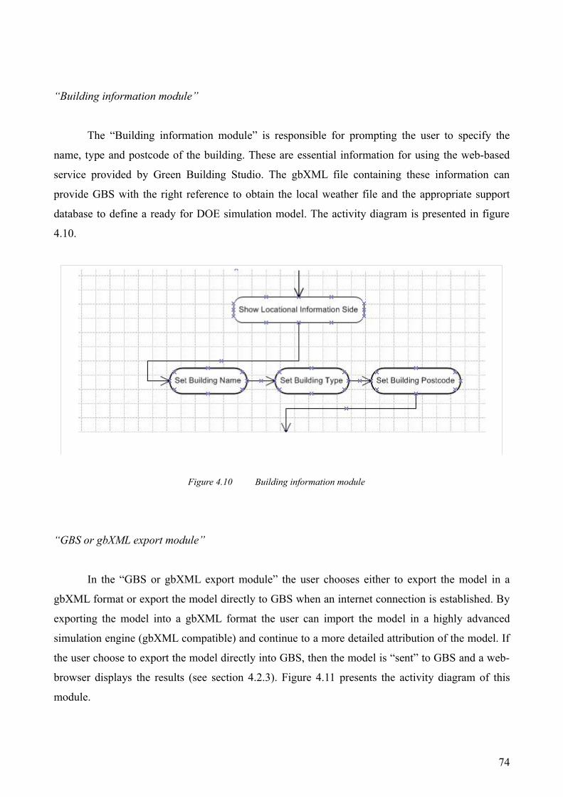
“Building information module”
The “Building information module” is responsible for prompting the user to specify the
name, type and postcode of the building. These are essential information for using the web-based
service provided by Green Building Studio. The gbXML file containing these information can
provide GBS with the right reference to obtain the local weather file and the appropriate support
database to define a ready for DOE simulation model. The activity diagram is presented in figure
4.10.
Figure 4.10 Building information module
“GBS or gbXML export module”
In the “GBS or gbXML export module” the user chooses either to export the model in a
gbXML format or export the model directly to GBS when an internet connection is established. By
exporting the model into a gbXML format the user can import the model in a highly advanced
simulation engine (gbXML compatible) and continue to a more detailed attribution of the model. If
the user choose to export the model directly into GBS, then the model is “sent” to GBS and a web-
browser displays the results (see section 4.2.3). Figure 4.11 presents the activity diagram of this
module.
74
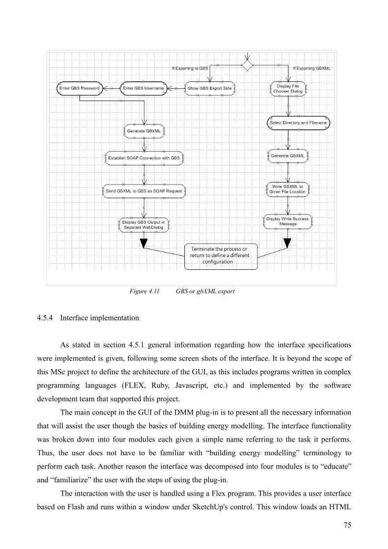
Figure 4.11 GBS or gbXML export
4.5.4 Interface implementation
As stated in section 4.5.1 general information regarding how the interface specifications
were implemented is given, following some screen shots of the interface. It is beyond the scope of
this MSc project to define the architecture of the GUI, as this includes programs written in complex
programming languages (FLEX, Ruby, Javascript, etc.) and implemented by the software
development team that supported this project.
The main concept in the GUI of the DMM plug-in is to present all the necessary information
that will assist the user though the basics of building energy modelling. The interface functionality
was broken down into four modules each given a simple name referring to the task it performs.
Thus, the user does not have to be familiar with “building energy modelling” terminology to
perform each task. Another reason the interface was decomposed into four modules is to “educate”
and “familiarize” the user with the steps of using the plug-in.
The interaction with the user is handled using a Flex program. This provides a user interface
based on Flash and runs within a window under SketchUp's control. This window loads an HTML
75

file which references the Flex program along with a JavaScript file. The plug-in can send text to this
program to notify it of any changes in the model or anything that the user has selected. SketchUp
takes the text from the plug-in and calls a JavaScript function. Calling JavaScript functions is a
method provided by the SketchUp API.
In order to reduce the amount of data presented to the user while navigating through the
modules (especially when dealing with large models) the concept of a “cube” GUI was introduced.
The “Cube interface” enables each side of the cube to represent a different module. Emphasis has
been paid to the transition between different faces of the cube by implementing features based on
Rich Internet Application9 built on FLEX. The Flex program contains different panels representing
each side of a cube. Each side responds to events sent from the Ruby plug-in and can send events
back to the plug-in in a similar way. Thus, the Ruby plug-in could start by sending a list of surfaces
to the Flex program. Each surface would then be added to a list of surfaces from within Flex.
After the user has selected a surface and changed its name, the Flex program would send the
ID of the surface along with the new name back to Ruby which would update the model
accordingly. The two programs store data independently but keep synchronised through this
communication. Figures 4.12 and 4.13 present different faces of the cube (i.e. different modules)
and figure 4.14 presents the interface in real practice. It is worth mentioning that the DMM plug-in
was renamed into “DEMETER-The SketchUp Green building extension” when the first phase of its
development was completed.
Figure 4.12 The space definition module face of the “Cube”
9 Rich Internet applications (RIA) are applications that have the features and functionality of traditional desktop applications. RIAs typically transfer the processing necessary for the user interface to the FLEX client but keep the bulk of the data back on the application software.
76

Figure 4.13 The Surface and Openings definition module face of the “Cube”
Figure 4.14 The GUI of the DMM plug-in in real practice
4.6 Closing remarks
This chapter initially described how the method proposed in the previous chapter was
implemented through the scope of this MSc project. The tools selected for each step of the method
77

reflect a structured approach to addressing the most significant reasons for the small uptake of
simulation within the conceptual design process of a building. The approach includes CAD
integration, ease of use and interoperability. The popularity of SketchUp, its free entry price and
intuitive design makes it ideal for the method. Green Building Studio was selected to provide the
web-based energy simulation and manipulation tool since its ability to accept gbXML files,
manipulate them by applying IDD and quickly define design alternatives in terms of orientation,
material use, HVAC configuration and lighting device efficiency, makes it ideal for the method. In
addition, the simulation is handled by a DOE 2.2 e engine running on the back-end of the
application. Despite the fact that DOE 2.2 cannot handle with daylight simulation, the results with
regards to the energy and environmental performance of the model are presented in an annual
basis. Thus, the conceptual designer can have a quick indication about the energy consumption of a
particular design proposal and test some design alternatives by using the “Design Alternatives”
function directly from GBS.
The chapter also deals with the specifications and the architecture of the DMM plug-in,
indicating the classes and the functions necessary to perform the required tasks. Not all of the
specifications mentioned in previous chapter where implemented in the DMM plug-in. This can be
partially attributed to the complexity of building advanced functions into the plug-in which exceeds
the scope of this MSc project. In addition, the implementation of the tool carried out during only the
last two months of the placement. Hence, the team focused on implementing some basic features
mainly for demonstration purposes. These features are related to the definition of the geometry of
the model, type of surfaces and sub-surfaces, building type and location.
The specifications of the DMM tool were defined through the use of the Data Mining
System (DMiS) and the data management system (DMaS). This dissociation was made so that the
development team and future developers can decompose what information is entering the system
(mining) and what is processed by the system (management). The general concept behind the
development of this plug-in was user functionality. Thus the majority of the processes are
automated while a few require some level of user interaction.
The model created in SketchUp contains a set of faces, edges and vertices. By letting the
faces represent surfaces and identifying to which spaces they belong, the basic gbXML structure is
created. The gbXML structure is built on a Ruby environment and contains spaces, surfaces, poly-
loops, rectangular and planar geometries (all essential elements of the gbXML schema). This
structure is stored in a group of classes within Ruby so that it can be easily accessed and modified
78

from different parts of the software.
The central concept in the development of the interface of the plug-in is to enable a non
expert in building energy modelling to define certain properties of a simulation model. Hence, a
considerable amount of effort was made to develop a “user objectives” model and a “user
interaction” diagram. These were used to design a user friendly interface. The specifications of the
interface are presented in an activity diagram where both automated and semi-automated processes
are included. The interface consists of several “modules”. The concept of modules was introduced
in order to help the user to understand the philosophy behind the tool. Four modules were
implemented in the GUI: The “Space definition module”, the “Surface and Openings definition
module”, the “Building information module” and the “Green Building Studio or gbXML file export
module”. In addition, the concept of a cube GUI was introduced. The “Cube interface” enables each
side of the cube to represent a different module.
After the completion of the first phase of development of the DMM plug-in, it was named as
“Demeter”. This reflects the aspirations of the development team to expand the capabilities of the
plug-in and test it within an actual architectural practice.
79

Chapter 5:
Further developments and Discussion
5.1 Introduction
In the previous chapter a detailed presentation of each component of the method was given.
In addition, the specifications and the architecture of the DMM plug-in were analysed and
discussed. This chapter provides general guidelines for future development of the proposed method
and the DMM plug-in. These guidelines are influenced by discussions with an architectural
practice, academia and personal views of the Author. Further development suggestions are
presented with regards to the method components and the functionality of the DMM plug-in.
Furthermore, the chapter gives an indication about additional uses of both, and discusses how these
can be implemented in practice. Finally, the applicability of the method and the DMM plug-in in
real practice is discussed and conclusions are made with regards to the final outcome of the project.
5.2 Feedback sources
The DMM plugin's functionality was not tested among the practitioners of the architectural
practice, due to time limitations. However. the particular architectural practice proved to be ideal for
getting feedback about the concept of the method. In more detail, the majority of the architects
interviewed stated that they would be very interested if a tool (or a sequence of tools) can provide
them with an indication of the energy rating of a particular design option. In addition, they all
agreed that the particular method has several advantages. However, as this will be indicated in
section 5.5, applying this method to real practice will not be an easy task.
The particular company does not have an in house energy modelling group. It collaborates
with an engineering firm so that the models are worked in greater detail (in terms of materials,
orientation, thermal mass, glazing area, etc.) in the conceptual design stage. Thus, building energy
simulation is not an in-house part of the design process. As a result, delays in deciding the optimum
design option are common since the engineering analysis often contradicts with the original design
option. Thus, the company's designers had to modify (and some times re-design) the building
design, slowing the delivery of the preferred design proposal.
Discussions with practitioners provided the Author with a better understanding about the
functionality the Conceptual designers would like to see from the DMM plug-in. In addition to the
80

“architectural” feedback, the specifications for further development were also influenced by the
Author's experience as a user of building energy simulation tools. Nevertheless, the method and the
plug-in was used and tested by all members of the development team and external stakeholders1
5.3 Comments about further development in the simulation engine
5.3.1 Introduction
The method, as it was implemented through the scope of this MSc project, uses DOE 2.2 e
as the simulation engine. Despite the fact that the engine is powerful [DOE 2007], it can not take
into an account several essential for the conceptual design stage parameters, such as creation of
optimized shading devices, shading device transmittance, Bi-directional shading devices, solar
radiation passing through interior windows (i.e. Sun-spaces), natural ventilation modelling and
many more [Crawley et al 2005]. However, as this was found in literature (chapter 2) and justified
within the architectural practice, shading design and control is an important aspect of conceptual
design. Ina addition, architects are aware of the visual implications of shading into their designs.
Thus, they have begun to consider shading as an important aspect in their designs [ARTI 2002].
By introducing a more detailed simulation engine at the back-end of the method (such as
ESP-r or EnergyPlus), several benefits can be drawn. It is not in the intentions of this dissertation to
provide details about these benefits. However, some of the drawbacks of DOE engine with regards
to the conceptual design stage are outlined in the Appendix (Table F).
5.3.2 Suggestions
In the previous section it was made clear that DOE engine lacks functionality in certain
aspects of design decisions taken at early stages of design. Thus, a new simulation engine should be
incorporated in the web-services of the “energy simulation and model manipulation” tool. As
mentioned in section 4.2.2, the structure of the EAM is of such that once enabled, alternative
simulation engines can be called. However, any new simulation engines hooked to EAM should full
fill certain criteria. These criteria refer to the fact that EAM is entirely centred around gbXML.
Thus, the new simulation engine should have its entities dictionary mapped to gbXML entities
dictionary. EAM's model then allows the new engine to be hooked into the system and the input file
generated from gbXML transform is run through this engine. In addition, the code will need to be
re-written to parse the results from the new engine's run and populate the originating gbXML file 1 External stakeholders were people who had interest in the development of the plug-in, including the CEO of
GeoPraxis.
81

with results (results are also stored in database). Even if the new engine has functionalities not
defined in the gbXML schema specifications, the gbXML definitions can be re-written2.
Incorporating a detailed simulation engine into the EAM's structure will allow the web-
service to move away from strategic early stage design and move into a full energy simulation
functionality from a web browser. This, in conjunction with modern programming languages
(FLEX, Java, etc.) and a detailed interface design practice, can result in a user-friendly energy
simulation software package. Thus, several issues related to the ease of use of simulation tools can
be addressed without the need to sacrifice functionality. An ambitious solution to the interface will
be the “User conceptualization” idea, which was initially proposed by Clarke and Mac Randal
[Clarke et al 1993]. According to this idea, the interface of a simulation engine will be able to
modify its functionality depending on the background of the user since different designers have
vastly different knowledge of energy and environmental modelling. In addition, the interface can be
automatically adjusted to provide functionality relevant to the needs of an experienced user
(modelling expert).
5.3.3 Additional uses of the method
Additional uses of the method can also take place. That is because particular components of
the method allow the quick geneation of a preliminary simulation model using a 3D CAD-
Sketching tool.
Currently SketchUp is used in several architectural schools as a stand-alone sketching tool
or as a part of CAD or BIM tools. In more detail, it is used for training into design workshops
which aim to familiarise the students with 3D Sketching tools [University of Liverpool 2007]. The
introduction of the a method that helps a non simulation expert to run an energy simulation and get
some feedback, will contribute to further student training with regards to energy consumption and
assessment. This feedback won't be accurate enough to be used for later use by architects though
(issue discussed at the conclusions section in this chapter). However, it can provide an indication
about how certain aspects of design (such as orientation, material use, glazing areas, etc.) can affect
the energy and environmental performance of a building.
5.4 Comments about further development of the DMM plug-in
2 Since gbXML schema is a XML schema, it can easily be re-written to include additional functionality
82

The DMM plug-in has reached the end of its first phase of development. The outcome of
this phase is a full working version of the DMM plug-in (which is now called “Demeter”) with
certain functionality as this was presented in chapter four. This section of the chapter deals with
future functionality of the DMM plug-in where indications, with regards to where development
should turn to, are discussed.
5.4.1 De-bugging
The DMM plug-in is a new software and thus, it requires a considerable amount of time to
be spend on de-bugging. This was found necessary throughout the development of the plug-in. If
the DMM plug-in is to be launched in the market as a supplementary tool to Green Building Studio,
the development team should must be sure that everything works smoothly so that user confusion
and frustration (and thus rejection) can be avoided.
An efficient way to proceed to the debugging process is to allow selected users within
architectural and engineering practice to use the beta version of the plug-in. A “bug tracking
system” such as Bugzilla3 will allow the development team to keep track of defects and bugs.
5.4.2 Further testing
One of the visions of the development team of the DMM plug-in is to turn a powerful 3D
sketching tool into a medium for defining geometry (and several other aspects of building energy
modelling) for energy simulation tools. To achieve this the DMM plug-in must pass certain
validation, verification and testing procedures so that an accurate model definition is ensured.
SketchUp is a tool of which capabilities can only be limited by the user's imagination4. The DMM
plug-in must be able to ensure that the entities created by SketchUp can be modelled for the needs
of an energy simulation, ensuring contiguity and consistency so that predictions correspond to the
the actual behaviour of the building. These checks should be based on a variety of geometry issues.
In addition, since the DMM plugin's Interface (Cube interface) is a very important part of the
functionality of the tool, it should be tested among practitioners to identify whether it responds to
users needs adequately or not (usability testing).
3 Bugzilla is one of the most widely recognised bug-tracking software. Vendors such as Eclipse, Open Office, Linux and several others are using it to track defects of their software.
4 According to the Author's and several users opinion
83

5.4.3 Quality Assurance reports (QA)
As mentioned in the previous section, performance predictions need to correspond to the
actual behaviour of the building. This check check can be carried out as a combined verification and
validation exercise. Verification deals with correct attribution of the simulation model and need to
be performed by a person familiar with the aspects and considerations about the purpose of the
simulation exercise. However, since this is not the case for the common user of the DMM plug-in,
algorithms that ensure model integrity and space contiguity should be further developed and tested.
Except the importance of verification and validation, the documentation of a simulation
model should also form an important part of the model definition process. One way of documenting
the model in the DMM plug-in is by summarizing its data information into a report. Initially this
report will contain information about floor areas, spaces volume, openings area, wall area, wall and
glazing area by orientation, etc. The designer would probably be familiar with these and thus the
report will provide an additional check that the model is defied as appropriate. In a future version of
the DMM plug-in, where more model definition functions will be supported, the QA report should
include all relative to the model information.
5.4.4 Construction types and material databases
Currently material and construction types are assigned to the model by the Green Building
Studio's Intelligent Default Data (IDD) system. As mentioned in section 4.2.2, this system uses the
user-provided information to attribute the preliminary simulation model using defaults based on the
building practices and codes based on UK standards. However, this does not enable the user to test
his/her own combination of materials and construction type.
A new class should be introduced to the main structure of the DMM plug-in so that the
definition of materials and construction type of each surface can be supported. It was found among
literature [ARTI 2002] and architectural practice that Conceptual designers are more familiar with
describing construction according to their U-values. Thus, the new class should include a list of
different construction types based on their U-values.
With regards to the interface adjustments required to implement the “Define the
construction type” function, a new face in the cube Interface should be added. Initially typical
constructions can be included in the construction type database which reflects UK standards.
However, each user should be able to define its own construction types according to company's
preferences or construction material provider.
84

5.4.5 Automatic space and surface type definition
Currently the user of the DMM plug-in can define the surfaces consisting a particular space
by simply clicking them through the SketchUp graphical environment. Despite the fact that this task
is relatively easy and within the knowledge of the user, the development team has identified the
need to simplify this process even more. An algorithm can be developed so that it can identify
relative, to the particular space, surfaces and match them to define an enclosed space. Another
function can contribute to the ease of use of the DMM plug-in by simplifying the surface type
definition process even more. An algorithm can have access to the tilt, azimuth and orientation of a
particular surface as well as the surrounding surfaces, so that it can make logical conclusions about
the type of the surface. However, both algorithms are based in computing combinations which can
dramatically slow down the functionality of the system and will require advanced computing
platforms
5.4.6 gbXML import to SketchUp
During the development period of the DMM plug-in all the efforts of the team were focused
on creating the appropriate dictionary mapping between SketchUp's geometry data to gbXML. This
was the primary functionality required from a tool such as the DMM plug-in. However, the opposite
process (gbXML into SketchUp) should be considered. By developing the appropriate scripts that
allow a gbXML file to be imported in SketchUp, functionality is increased.
5.4.7 Guided input process and link to cost calculations
As mentioned in section 3.4.2, introducing conceptual design wizards into the model's
creation process can assist the designer in the model definition. However, compiling a wizard for
the conceptual design stage is not a trivial task and requires extended research among practitioners.
Data exchange between cost estimation tools and the DMM plug-in will be based on the
usage of a reference database that can be updated. The consistency of this database must be ensured
so that accurate costing is achieved. In addition. the system should be designed according to what
kind of functionality the user is familiar with (similar to the approach of this MSc project about the
CAD-Sketching integration). With regards to the interface of the plug-in, a new face should be
added. The ease of use of this addition to the cube interface should reflect the functionality of
85

costing tools that the conceptual designer is familiar with.
Introducing costing functions to the DMM plug-in will not be an easy task. Costing
exercises are based on the concept of zones and surfaces [Morbizer 2003]. Despite the fact that
basic definition requirements can be easily carried out through the DMM plug-in, the difficulty will
be to link the functionality with a well established coherent set of data.
5.4.8 Design alternatives
One of the main advantages of Green Building Studio is its ability to allow the user to define
design alternatives (orientation, lighting devices control and efficiency, construction types varying
with the orientation of the walls, roof construction type, HVAC configuration and glazing type).
However, the accuracy of these transformations can be the outcome of another research since the
functions that currently support these features are not clear enough5. However, this functionality can
be transferred into the DMM plugin's main structure and interface. Hence, the user can have the
“design alternatives” functionality of GBS within SketchUp. With regards to the interface of the
plug-in, the additional functionality can be represented as an extra face in the cube interface. The
user should be able to specify a series of design alternatives (orientation, construction type, glazing
areas, etc.) and then store these preferences into a different gbXML file for each alternative. When
the user chooses to upload the model(s) to GBS platform he/she can get feedback for the original
model and the design alternatives.
5.4.9 Support several format imports and exports
Several state-of-the-art simulation tools support certain types of geometry file format (see section
2.5). However, these tools lack CAD integration from a conceptual designer's point of view.
Developing modules that support the transformation from gbXML to IFC (or any other format) and
vice versa, will provide an even more stronger link between building energy simulation tools and
CAD-Sketching tools. In addition, all the information related to the zone and surface attribution
made while using the DMM plug-in can be imported into a wider6 variety of simulation tools. The
same feature can be used by engineers while the building is at the Scheme and Detailed design
stage, reducing the amount of time required to define the geometry of the simulation model.
5 This conclusion is made from the Author's personal experience. However, investigating the functions that support these transformations is beyond the scope of this MSc project.
6 Currently IES (virtual environment), EnergySave, Loadsoft, HAP, Energy-10 and Trace® 700 can import gbXML files
86

Several benefits derive from the opposite process (other format types to gbXML). If
geometry files created in any CAD or BIM tool can be imported to SketchUp, processed by the
DMM plug-in and then exported to GBS or to a more advanced simulation tool, the terminology
between architecture and engineering is a step forward to merging. However, this is not likely to
occur without sacrificing some functionality. GbXML schema was originally developed as a
language that enables data exchange between CAD-BIM and energy simulation tools, However, it is
a relatively new schema and thus should be used with cautiousness.
5.5 Discussion about the DMM plug-in and the method
When the Author had the opportunity to present and discuss the use of the DMM plug-in and
the method to the architectural practice, a functional version of the tool was completed. As
mentioned earlier in this chapter the method was not tested among practitioners. However, the
Author had enough time to present the method (and the DMM plug-in in particular) and discuss its
functionality among potential users.
The DMM plug-in was originally developed without having the knowledge of how
SketchUp is used among conceptual designers. The idea of representing a single surface as a wall
proved to be not very functional when the plug-in was introduced to practitioners of the
architectural practice. Architects are used to representing a wall with its associated thickness in a
CAD environment. This kind of visual representation is uncommon among energy modelling and
simulation practitioners ( a wall is usually represented as a single surface). However, when the
building is still in the conceptual design process, visualization is an important issue for architects.
The 3D CAD tools are mainly used for providing a visual representation of the building as this will
be delivered to the client.
The SketchUp models presented to the Author by the conceptual designers of the
architectural practice, contained high level visual representation of the building (wall and roof
finishes, window fittings, shading devices, etc). A test, undertaken from the development team, of
whether or not the DMM plug-in can handle with these SketchUp models, indicated that the
building can still be modelled using the DMM plugin's functionality but not without sacrificing part
of its ease of use. It was found that modelling (in terms of energy) a detailed visual representation
of a building in SketchUp7 required special skills8 and thus, increasing the complexity of the
modelling exercise and reducing the likelihood of adoption by designers.
7 As this will be generated from a conceptual designer8 However, according to the Author's opinion, these skills can be easily obtained.
87

Another important issue deriving from the “visualization priority” among architects, is that
of an accurate model geometry definition. The DMM plug-in requires a 100% accurate geometric
definition of the model in SketchUp. This fact somehow contradicts to the normal use of 3D in
CAD, where the aim is to produce a visual representation of the building as this will be delivered to
the client. In the visual representation of a building, drawing inaccuracies are acceptable as long as
they do not impact on the visual quality of the drawing.
It is a general fact that designers will not take energy performance into a deep consideration
if it weren't for the building regulations. Nowadays, the regulations impose an environmental
friendly and thus, energy efficient way of designing. However, as this has been found in literature
and proved within the architectural practice, compliance is the most desired outcome of an energy
analysis.
The overall objective of this MSc project is the development of a tool that enables the user
to get a quick energy and environmental performance prediction analysis. The approach taken to
address this issue is made by a series of assumptions so that the process is as simplified as possible.
This generates questions about the accuracy of the results of the method (i.e. does the default
occupancy type assigned by Green Building Studio accurately represents the actual use of building
by occupants?). Thus, the use of the method, as implemented through the scope of this MSc project,
can not be used for checking compliance with building regulations. The Green Building Studio's
features, as these were implemented in the method proposal, can not be used for compliance check.
This is because the complete model attribution is made using “default” values for building
components that can dramatically effect energy performance (and thus compliance). The main focus
of the proposed method is to provide the conceptual designer with an indication of whether a
particular design is on the right path to achieve compliance or not.
The use of “default” values should be reconsidered and carefully analysed when developing
a conceptual design tool to be used for compliance check (Morbitzer 2003). The accuracy of the
“default” values assigned from Green Building Studio should be further tested to find out whether
or not can create design guidelines, as well as up to what extent reality is represented. Thus the
method can have a more strategic purpose. However, validating the accuracy of the predictions is a
complex issue and paucity of consensus about “defaults” is the main reason for this.
There are also several other issues deriving from the accuracy of the prediction analysis
provided by Green Building studio. These can be mainly attributed to the simulation engine located
in the back-end of the process. DOE 2.2 cannot take into an account several parameters that can
affect energy performance in a building and has limited modelling capabilities compared to other
88

simulation tools. These are outlined9 in table G in the Appendix, for referencing reasons. In the
same table, the capabilities of a more advanced energy simulation tool (ESP-r), are contrasted. A
full report about the capabilities of each the tool, as well as several other simulation tools, can be
found in literature [Crawley et al 2005].
5.6 Conclusions
In the last two chapters of this dissertation, a detailed description of a method was given.
The main objective of this method is to provide Conceptual designers with strategic advice about
certain aspects of conceptual design. The method consists of a sequence of two tools and three steps
(figure 5.1) and aims to address some of the most significant barriers to the adoption of simulation
into the conceptual design stage: CAD integration, ease of use and interoperability.
Figure 5.1 Method composition
The use of SketchUp for the CAD integration was made considering three essential
parameters: its ease of use, its 3D sketching capabilities and the fact that it is the most popular 3D
sketching tool among designers [Vanguard 2006]. For the needs of this method, a Data Mining and
Management plug-in to SketchUp was developed. Among the plugin's main responsibilities is to
“extract” information about the geometry of the model created within SketchUp and manage them
so that an accurate preliminary simulation model is created. The preliminary model is then uploaded
to the Green Building's web-based platform for further manipulation, by using Intelligent Default
Data (IDD) so that a complete for simulation model is created. Then a simulation is undertaken by
DOE 2.2 engine and the results are “sent” to the user and presented in a web-browser.
9 The modelling capabilities of DOE 2.1 (a similar to DOE 2.2 engine) are presented in this table.
89
Method composition
3D CAD-Sketching tool(Google's SketchUp and DMM plug-in)
Model manipulation and energy simulation tool(Green Building Studio)
Step 2Step 1 Step 3
First Tool Second Tool
Model definition (geometry) Model preliminary attribution
Model further attribution, simulation and results presentation
The method, and thus the DMM plug-in, were originally developed with the aspiration to
provide strategic design advice to conceptual designers about certain aspect of design relative to
early design stage. However, the first two steps of the method can be used to define a geometry
model using the flexibility and the ease of use of SketchUp, to attribute the model in terms of
spaces, surfaces and openings by using the attribution functions of the DMM plug-in and finally, to
export the model into a gbXML format. Thus, the model can be inserted into an advanced
simulation engine (gbXML compatible) for further attribution and simulation.
The user input requirements of the DMM plug-in are related to space definition and surface
attribution. Also, the user is required to provide the use and location of the building. However,
future versions of the DMM plug-in will probably require more user inputs to provide more
strategic design decision support. Emphasis has been paid to simplifying the process by using
assumptions based on the current user interactions. Thus, a detailed study has been carried out so
that specific user requirements are translated into operating tasks. In addition, the development of
the user interface was developed according to development team's conceptualization about ease of
use.
The strategic design decision support is provided by the web-services of Green Building
Studio. According to these services, the user by defining the “post code” of the building can inform
Green Building Studio as to which weather file to use for the simulation. The model is further
attributed in terms of occupancy type, occupancy level, internal heat gains, HVAC configuration
and air change rates, according to the building use specified by the user. Green building Studio uses
these user-provided information to assign “defaults” based on building practices and codes for the
UK. However, this generates questions about the accuracy of the results of the method (i.e. does the
default internal heat gains or HVAC configuration assigned by Green Building Studio accurately
represents the building?). Thus, the use of the method, as this was implemented through the scope
of this MSc project, can not be used for checking compliance with building regulations.
Nevertheless, if a relative consensus among researches is achieved with regards to “defaults”, then
the method can provide more “accurate” strategic design decision to the end user. In addition to the
issues with the “defaults”, questions are also raised regarding the simulation engine. For example,
DOE engine cannot handle with time steps less than an hour. However, in order to accurately
represent the effect of a particular HVAC configuration, time steps of less than an hour must be
taken into an account.
Currently the method can provide the user with strategic design decision advice about the
following design aspects:
90

➔ Orientation
➔ HVAC configuration (choose among a variety of systems)
➔ Lighting efficiency
➔ Lighting control
➔ Roof construction type
➔ Northern façade (choose from a variety of construction type, glassing type and
glazing/wall ratio)
➔ Southern façade (choose from a variety of construction type, glassing type,
glazing/wall ratio)
➔ Eastern façade (choose from a variety of construction type, glassing type,
glazing/wall ratio)
➔ Western façade (choose from a variety of construction type, glassing type,
glazing/wall ratio)
These changes are operated by the “design alternatives” functions of GBS. The design
alternatives are based on certain kind of transformations undertaken by the GBS' web platform.
According to the Authors opinion, the functionality provided to the end user is considerable and can
represent some of the needs and priorities of Conceptual designers. However, the functions
supporting these transformations should be the centre of extended research so that accuracy is
ensured.
As this was mentioned in section 2.4 and proved among architectural practice (section 5.5),
ease of use can be eclipsed provided “visual representation” priorities among conceptual designers.
In addition, any model drawing inaccuracies in the sake of visual quality, are common among
conceptual designers. The DMM plug-in requires 100% accurate geometry definition. However, the
DMM plug-in can still handle complex geometries and detailed models generated in SketchUp. The
model can be attributed in the DMM plug-in, as this was investigated among the development team,
but it will take more time and effort, and require some guidance (at the beginning). Thus the tool is
more likely to be rejected among practitioners.
Another use of the DMM plug-in is also promising from a user perspective. The plug-in can
be used in conjunction with SketchUp to easily define the geometry of a model and assign attributes
to it, in terms of space definition, surface and openings type and construction types. These
information can be saved in a gbXML format and exported into an advanced simulation tool for
91

further attribution by a simulation expert. Thus the time required to define a simulation model is
reduced and the same geometry model is used throughout all the design stages (Conceptual-
Scheme-Detailed)
According to the Author's point of view, this project addresses some of the major problems
responsible for the small uptake of simulation into the conceptual design stage by proving a link
between a powerful 3D sketching tool and building energy simulation tools. The benefits can be
found among conceptual designers, since a strategic Design Decision Support System is provided,
as well as other stakeholders, since the generation of a simulation model (in terms of geometry and
certain attribution) is supported by an easy to use but still powerful 3D sketching tool.
The final outcome of this MSc project, is the development of plug-in that enables different
level of experienced users to take advantage of its capabilities and reduce the time required to
perform certain aspects of building energy modelling. The plug-in is currently under further
development to support more functionality and thus become even more useful among designers.
Verification and testing are still under way to ensure that the model is generated as accurately as
possible according to building energy modelling techniques. In addition, several other issues, such
as the use of “defaults”, transformation functions in “design alternatives” and incorporation of
more advanced simulation engines, will also addressed in the foreseeable future.
References
Abdeen 2007, Abdeen M., “Energy, environment and Sustainable development”, Renewable and Sustainable Energy Reviews, article, available on ScienceDirect, 2007
ARTI 2002, “State of the Art Review of Building Simulation and Design Tools”, Air conditioning and Refrigeration Technology Institute (ARTI), report available at http://tc47.ashraetcs.org/pdf/Presentations/Jacobs_Cincinnati.pdf
Baker N V, Steemers K, “The LT Method, Version 2 – an Energy Support Tool for Non domestic Buildings” (The LT Method was Developed by the Martin Centre for Architectural and Urban Studies, Cambridge and is Available from the Royal Institute of British Architects, RIBA)
Bilda et al 2006, Bilda Z., John S., Pucell T., “To Sketch or not to Sketch? That is the question”, Key Centre of Design Computing and Cognition, University of Sydney, NSW 2006, Australia
Brunel University 2000, “Exploring Design and Innovation – Fresh Ideas for Creative Curriculum Development”, Published by the Department of Design at the Brunel University with Support from the Design Council, 2000.
92

BRE 2005, “Rammed earth: Design and construction guidelines”, British Research Establishment, 2005, BRE publications
Building design 2007, Web site, retrieved on September 2007 from:http://www.buildingdesign.co.uk/arch/buildingsimulation/buildingsimulation.html ,
CIBSE 1998 CIBSE, “Building Energy and Environmental Modelling”, CIBSE Application ManualAM 11, CIBSE, 1998.
Clarke et al 1993, Clarke J.A., MacRandal D., “The intelligent Frond-End: Background, Structure and Operation”, University of Strathclyde, Scotland UK. Available on request: [email protected]
Clarke 1997 Clarke J A, “Building Performance Simulation Using the ESP-r System”, ProceedingsBuilding Simulation 97, Prague 1997.
Clarke et al 1993 Clarke J A, Mac Randal, “Implementation of Simulation Based Design Tools in Practice”,Proceedings Building Simulation 93, Adelaide, pp 423-429, 1993.
Clarke 2001, Clarke J A, “Energy Simulation in Building Design”, Butterworth-Heinemann, Oxford,2001.
Crawley et al 2005, Crawley D., Hand J.,Kummert M., Griffith B., “Contrasting the capabilities of building Energy Performance Simulation Programs”, Joint Report, US department of Energy – Energy Systems Research Unit – University of Winsconsil – National Energy Laboratory (US), July 2005
Donn 1997 Donn M R, “A Survey of Users of Thermal Simulation Programs”, pp 65-72, ProceedingsBuilding Simulation 97, Prague, pp 65-72, 1997.
DOE 2007DOE (US Department of Energy), “Energy Tools Directory”, www.energytools.gov, 2007;
gbXML schema 2007, Web site, retrieved on August 2007 from: http://gbxml.org/index.htm
Gero et al 1983, Gero J S, D’Cruz, Radford A D, “Energy in Context: A Multicriteria Model for Buildind Design”, Building and Environment, Volume 18, No 3, pp 99-107, 1983.
Green Building Studio, 2007, Web site, retrieved on July 2007 from: http://www.greenbuildingstudio.com/gbsinc/index.aspx
GreenSpace research 2006, see [Vanguard 2006]
Hand 1998, Hand J W, “Removing Barriers to the Use of Simulation in the Building DesignProfessions”, PhD Thesis University of Strathclyde, 1998.
Hensen 1991Hensen J L M, “On the Thermal Interactions of Building Structure and Heating andVentilation Systems”, PhD Thesis, Technische Universiteit Eindhoven, 1991.
Hensen 1994, Hensen J L M, “Energy Related Design Decisions Deserve Simulation Approach”,Proceedings of the International Conference on Design and Decision SupportSystems in Architecture & Urban Planning, Vaals, 1994.
93

Henrikson 2000 Henrikson C, “The Bigger View - Optimising Solar Energy Use in Large Buildings”,Renewable Energy World, Vol. 3, No. 3, 2000.
Hien W N, Poh L K, Feriadi H 2000, “The Use of Performance-based Simulation Tools for Building Design and Evaluation – a Singapore Perspective”, Building and Environment, Volume 35, pp 709-736, 2000.
Hitchcock 2002, Hitchcock R., “Software Interoperability for Energy Simulation”, eScholarship Repository, University of California, http://repositories.cdlib.org/lbnl/LBNL-51244
Interface Concepts 2007, Information retrieved from web site on June 2007, http://www.interfaceconcepts.com/
Jones 2001, Jones P b, “Energy in Buildings”, Workshop organised by the Chartered Institution ofBuilding Services Engineers (CIBSE), Manchester, 2001.
Laaroussi, A., A. Zarli, et al. 'An approach to modelling the dynamics of the design process in architecture' viewed 20 November 2005, http://www.crai.archi.fr/media/pdf/32_laaroussi.pdf.
Lawson 1990, Lawson B, “How Designers Think – The Design Process Demystified”, ButterworthArchitecture, 1990.
Lechner 2001,Lechner N, “Heating, Cooling, Lighting – Design Methods for Architects”, John Wileyand Sons, 2001.
Macdonald et al 2005, MacDonald I.,McElroy B., Hand W., Clarke J.A., “Transferring simulation from specialists into design practice”, Proceeding of 9th International IBPSA conference, Montreal, Canada, 2005
Mahdavi et al 1993 Mahdavi A, Hartkopf V, Loftness V, Lam K P, “Simulation-based Performance Evaluation as a Design Decision Support Strategy: Experiences with the Intelligent Workplace”, Proceedings Building Simulation 93, pp 185-191, 1993.
Mahdavi 1999, Mahdavi A. “A comprehensive computational environment for performance based reasoning in building design and evaluation”, Automation in Construction Vol. 8 pp 427–435, 1999
Mahdavi et al 2004, Mahdavi A., Lam K.P.,Wong N.H, Chan K.K., Kang Z., Gupta S., “SEMPER II: an internet-based multi-domain building performance simulation environment for early design support”, Automation in construction Vol. 13 pp 651-663, 2004
Mahdavi 1998, Mahdavi A.“Computational Decision Support and the Building Delivery Process: a Necessary Dialogue”, Automation in Construction, Vol. 7, pp 205-211, 1998.
Morbitzer 2003, Morbitzer C. A. , “Towards the Integration of Simulation into the Building Design Process”, PhD thesis, Energy Systems Research Unit, University of Strathclyde, Glasgow, 2003
Mortbitzer et al 2003, Morbitzer C., Hobbs D., Spires B., Strachan P., Webster J., “Experience of using building simulation within the design process of an architectural practice ”, Proceedings of the 8th international IBPSA conference, Eindhoven, Netherlands, 2003
94

NREL 2002 NREL (National Renewable Energy Laboratory), ”Energy 10 Homepage”,http://www.nrel.gov/buildings/energy10, 2002.
Obanye 2005, Obanye I., “Integrating Building Energy Simulation into the Architectural Design Process”, 2005
Pohl et al 2000, See [Robinson 1996]
PIER 2002, “Conceptual Design Energy Analysis Tool: Research and Development - Final Report”, California Energy Commission, Public Interest Energy Research, Available on: http://www.energy.ca.gov/pier/final_project_reports/500-02-038f.html
Rafiq et al 2005, Rafiq Y. Beck M. Packham Ian, Denham S. ,”Evolutionary Computation and Visualization as Decision Support tools for Conceptual Building Design”, Innovation in Civil and Structural Engineering, Chapter 3 pp 49-74, Saxe-Coburg Publications
RIBA 1995 RIBA (Royal Institute of British Architects), “Architect’s Job Book”, RIBA Publications,1995.
RIBA 2007, “Green guide to the architects job book. 2nd edition”, Royal Institute of Buildings Architects, RIBAPUBS
Robinson 1994, Robinson S, “Successful Simulation – a Practical Approach to Simulation Projects”,McGraw-Hill Book Company, 1994.
Robinson 1996, Robinson D, “Energy Model Usage in Building Design: a Qualitative Assessment”,Building Services Engineering Research and Technology, Vol. 17, No. 2, CIBSE,pp 89-95, 1996.
SketchUp API developers guide 2007,retrieved from SketchUp's main page: http://download.sketchup.com/sketchuphelp/gsu6_ruby/Docs/index.html
Strachan et al 2003, Strachan P A Morbitzer C, Hobbs D, Spires B, and Webster J, “Experience of using building simulation within the design process of an architectural practice”, Proceedings of IBPSA, Eindhoven, 2003
Sustainable Architecture and Building Design 2007, Web site, retrieved on July 2007 from: http://www.arch.hku.hk/research/BEER/sustain.htm,.
TRADA 2007, “Energy Performance Certificates (EPC's): A summary of requirements”, report, TRADA construction briefings, UK, June 2007 (version 1),
University of Liverpool 2007, Web site, retrieved on July 2007 from: http://blog.miragestudio7.com/2006/05/sketchup-tutorials-university-of-liverpool/
Vanguard 2006, “Survey Results & Analysis for Greenspace Research Web Survey FINAL”, survey commissioned for GreenSpace Research, available on request: [email protected]
95

APPENDIX
Table A
Work Stage Description A: Inception Discuss the client’s requirements including timescale and
financial limits; assess these and give general advice on how to proceed
B: Feasibility Carry out a study to determine the feasibility of the client’s requirements.
C: Outline Analyse the client’s requirements; prepare outline proposal and an approximation of the construction cost.
D: Scheme Develop a scheme design sufficiently accurate to illustrate special arrangements, materials and appearance.
E: Detail Detailed definition of design.
F and G: Productionand Bills
Prepare production information (drawings, materials, workmanship);prepare bills of quantities.
H: Tender Invite tenders.
J: Project Planning Appointment of contractor.
K: Operation on site Administer construction operations on site.
L: Completion Guidance to maintenance, provide drawings to client, including service installations.
M: Feedback Occupiers evaluate building.
Table B
Practitioner design tools CAD environmentsLighting design tools Architectural visualization tools Fenestration selection tools Shading/ solar angle tools Code compliance tools Single-zone load tools Multi-zone HVAC system load toolsDuct sizing/ layout tools Cost estimating tools
96

Integrated design suites HVAC product selection and configuration tools Engineers 'Toolbox'Pipping analysis and Pump sizing tools IAQ/ standard 62 compliance toolsPsychometric tools Refrigeration load tools Coil selection tools Geothermal HP loop sizing tools Acoustic analysis tools Solar DHW/ PV system design tools Weather tools and utilities
Table CWhole building energy analysis tools Simplified energy analysis models (DD, bin analysis, day profile per month)Basic hourly simulation models (calculator engines)General hourly simulation models Special purpose simulation models Screening tools
Table D
Economic and Environmental tools General life cycle tools Technology screening/assessment tools Environmental impact assessment tools
Table E
Specialized analyses tools Daylight / Illumination tools models Fenestration models Infiltration / pollutant / Pressurization models 2D and 3D heat and moisture transfer models Computational fluid dynamics models Equation based solvers General component-based mechanical models
97

Refrigeration systems (hardware-based) models Refrigeration system (performance-based) models
Table F
Space temperature based on loads-systems feedback feature not supported Number of surfaces, zones, systems and equipment limited Human thermal comfort function not supportedBeam solar radiation reflection from outside and inside window reveals feature not supportedSolar gains through blinds feature not implemented Solar gains and daylighting calculations for inner reflections form external buildings feature not supported Creation of optimized shading devices feature not supported Shading surface transmittance feature not supported Beam solar radiation passes through interior windows (double-envelope) feature not supportedTrack insolation losses (outside of other zones)Electrochromic glazings feature not supported Thermochromic glazing feature not supported Inside radiation view factors feature not supported Geometrically and optically complex fenestrations systems using bidirectional transmittance feature not supported Daylighting devices feature not supported Airflow windows feature not supported Phase change materials feature not supported
Table FConceptual design variables not supported by DOE engine [full report available from Crawley et al 2005]
Table G
Modelling approach DOE 2.1 E ESP-rSimulation solution Simultaneous loads, systems and plant solution n yCoupled loads, systems and plant solution n yTime step approach Variable time intervals for zone air/HVAC system calculation
n y
Less than an hour n yInterior surface convectionDependent on temperature n y
98
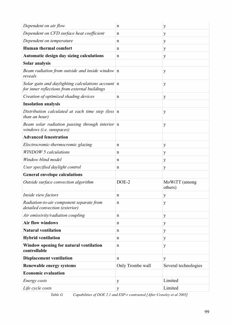
Dependent on air flow n yDependent on CFD surface heat coefficient n yDependent on temperature n yHuman thermal comfort n yAutomatic design day sizing calculations n ySolar analysis Beam radiation from outside and inside window reveals
n y
Solar gain and daylighting calculations account for inner reflections from external buildings
n y
Creation of optimized shading devices n yInsolation analysisDistribution calculated at each time step (less than an hour)
n y
Beam solar radiation passing through interior windows (i.e. sunspaces)
n y
Advanced fenestration Electrocromic-thermocromic glazing n yWINDOW 5 calculations n yWindow blind model n yUser specified daylight control n yGeneral envelope calculations Outside surface convection algorithm DOE-2 MoWiTT (among
others)Inside view factors n yRadiation-to-air component separate from detailed convection (exterior)
n y
Air emissivity/radiation coupling n yAir flow windows n yNatural ventilation n yHybrid ventilation n yWindow opening for natural ventilation controllable
n y
Displacement ventilation n yRenewable energy systems Only Trombe wall Several technologies Economic evaluation Energy costs y LimitedLife cycle costs y Limited
Table G Capabilities of DOE 2.1 and ESP-r contrasted [After Crawley et al 2005]
99