Embed Size (px)
Citation preview
111Copyright © 2005 Cisco Systems Inc
Next Generation Broadband Networks
John HarperVice President, IOS Routing
Apricot 2005
222Copyright © 2005 Cisco Systems Inc
Next Generation Broadband Networks
• The broadband opportunity, in Asia and worldwide
• Cisco R&D for the broadband opportunity• IP-Optical Integration: building broadband
networks efficiently• Early-adopter example of IP+Optical
integration

333Copyright © 2005 Cisco Systems Inc
Broadband driving factors in Asia
• Asia is world-leader in...– True broadband access (up to 100 Mbit/sec
commonplace)– Mobile communications (3G and beyond)
• Significantly ahead of other geographies• Unique situation with IPv6 adoption

444Copyright © 2005 Cisco Systems Inc
Network Growth - the need for broadband
• Only a true optical layer can accommodate such traffic growth!!!
Japan: Max/Min Traffic Volume ! 100x in 5 years
Source: http://www.jpix.ad.jp/jp/techncal/traffic.html
555Copyright © 2005 Cisco Systems Inc
Broadband in Asia – Implications for Cisco
• Need to benefit from this leadership…• …and apply to products for worldwide market• Conclusion:
Create development centre in Tokyo!
666Copyright © 2005 Cisco Systems Inc
Cisco Japan Development Center (JDC)
• Software development for worldwide markets…• …defined by Japanese requirements• Development of features for IOS and IOS-XR router
software:– Intelligent Edge– IPv6– IP Mobility
• Initially 10 engineers, based in Tokyo

777Copyright © 2005 Cisco Systems Inc
Broadband Network Core ArchitectureIP+Optical Integration

888Copyright © 2005 Cisco Systems Inc
How to support this broadband growth?
• More core bandwidth• Dense Wave Division Multiplexing• IP+Optical Integration
999Copyright © 2005 Cisco Systems Inc
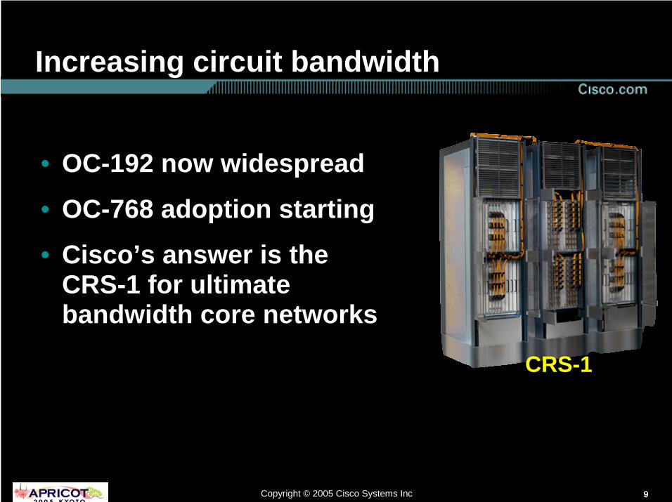
Increasing circuit bandwidth
• OC-192 now widespread• OC-768 adoption starting• Cisco’s answer is the
CRS-1 for ultimate bandwidth core networks
CRS-1CRS-1

101010Copyright © 2005 Cisco Systems Inc
Cisco’s IP+Optical Strategy:Building blocks & Technologies
CISCO INNOVATIONCISCO INNOVATION
ManagementIntegration
ManagementIntegration
Control Plane Integration
Control Plane Integration
IP/Optical Element
Integration
IP/Optical Element
Integration
101010© 2004 Cisco Systems, Inc. All rights reserved.NGN_0401
" IP/Optical Element Integration:" 10G DWDM interfaces on routers as an entry
point into the optical domain" 40G DWDM interface over 10Gbps transport" 2.5G WDM for lower end applications" Advanced LH DWDM layer w extensive
optical control loops and monitoring" Ring Optical Switching using ROADMs" Mesh Optical switching using λλλλ Routers
" Control Plane Technologies:" LMP" Peer model (GMPLS)" Overlay model (O-UNI)
" Network Management Integration
IP+Optical Integration

111111Copyright © 2005 Cisco Systems Inc
World’s First 40G IP Transmission:Power by Cisco CRS-1 and MSTP (DWDM) over MCI Infrastructure
MCI PoP – San FranciscoCisco CRS-1
Single-Shelf System
MCI PoP – San JoseCisco CRS-1
Single-Shelf System
CiscoONS 15454
MSTP
CiscoONS 15454
MSTP MCIFiber Plant (104 KM)
Computer History Museum
Cisco CRS-1
Multi-Shelf System
OC-768
OC-48
OC-768
Cisco12000
Cisco12000
Cisco CRS-1
Single-Shelf System
CiscoMDS 9216
CiscoMDS 9216
TesterTester TesterTester
OC768 Tester
OC-768
Agilent

121212Copyright © 2005 Cisco Systems Inc
IP+Optical Integration
• Packet layer convergence to IP/MPLS is starting to deliver CAPEX and OPEX savings in core networks
• 20%-40% additional CAPEX/OPEX saving can be had by converging the IP layer and the optical layer
• The building blocks exist: core routers, DWDM layer (MSTP), and converged management and control efforts
FR ATM Voice IP
CC IP / MPLS
TDM
Optical
λλλλ servicesSAN

131313Copyright © 2005 Cisco Systems Inc
IP+Optical Building blocks
• Goal: end-to-end optical layer onto which TDM, IP & λλλλ services converge
• This solution includes 4 elements:
1. Colored interfaces directly on the router
2. A Switched Converged Open Optical Layer
3. Integrated management4. Integrated control plane
Router Optical Layer
Unified Control Plane
Unified Management

141414Copyright © 2005 Cisco Systems Inc
Cisco’s IP+Optical Strategy:Base Architecture
WDM I/F
WDM I/F
Optical switching via 15454 MSTP
CRS-1, 12000, 7600
WDM PLIM/ SPA for 2.5G, 10G and
40G λλλλs
DWDM LH transmission to other sites via MSTP
• Optical bypass – without OEO conversion for lowest costRegens introduced as needed for very long connections (>1000 km)
OOB signaling over Ethernet
Innovative extensions to GMPLS to make is DWDM aware
CTM managing CRS-1 and 15454 MSTP today

151515Copyright © 2005 Cisco Systems Inc
CAPEX Issues with Current ArchitectureMany non-revenue generating costly interconnections
WDM Transport
CrossConnect
(EXC)
CrossConnect
(EXC)
IP Source/Sink Nodes Transit Nodes
WDM Transport
SR (W)
SR (W)
SR (W)
TXP (W)
SR (W)
SR (W)
TXP (W)
SR (W)
SR (W)
SR (W)
TXP (W)
SR (P)
SR (P)
TXP (P)
Issues:1. High CAPEX –
especially at 40G!2. High OPEX: power
consumption & footprint
3. Lower reliability

161616Copyright © 2005 Cisco Systems Inc
Cisco’s IP+Optical Strategy:Simplifying the Network and Reducing its Cost
Open Switched Optical Mesh
IP Source/Sink Nodes Transit Nodes
TXP (W) TXP (W) TXP (W)TXP (P)
Open Switched Optical Mesh
Issues solved:1. Racks of
transponders eliminated
2. Reduced number of O-E-O conversions increases reliability

171717Copyright © 2005 Cisco Systems Inc
Next Generation Optical Layer
Automated optical layer for end-to-end connection setup; Manual patching of client at
end-points only
Easy planning with
sophisticated tool
Simplified, graphical A-Z lightpath provisioning & trouble shooting via CTM
Planning & simulation tool
Sophisticated EMS
Auto Node Setup
ROADM
Auto Power Control
True power measurement

181818Copyright © 2005 Cisco Systems Inc
IP/MPLS
The Switched Open Optical Convergence Layer:Also for TDM Trunks and Optical Services
One optical layer for packet and TDM client, as well as future high bandwidth “λλλλ on demand”
Tunable WDM I/F
SONET/SDH
Tunable TransponderWavelength
service
XFP

191919Copyright © 2005 Cisco Systems Inc
The Switched Open Optical Convergence Layer:Advanced capabilities
• Flexible switching in the network from day 1:– Any router can connect over switched optical layer to any peer router
• Providing hooks for future advanced capabilities via software upgrade:– In case of optical layer failures, the optimal response may be
restoration in the optical domain – need fast end to end coordination
WDM I/F
WDM I/F
Router Optical Layer
RSVP setup

202020Copyright © 2005 Cisco Systems Inc
The Switched Open Optical Convergence Layer: How is it “Open”?
• The Optical Convergence Layer needs to be open in 2 ways:
1. Any client can connect to the optical layer via transponder or colored interface
2. The ITU interfaces on routers can directly connect into any optical layer
• The use-cases for both are:1. Non-Cisco clients connected
over converged optical layer (DXCs, MSPPs, WL services)
2. Cisco routers working over non-Cisco optical layer
Optical handoff
212121Copyright © 2005 Cisco Systems Inc
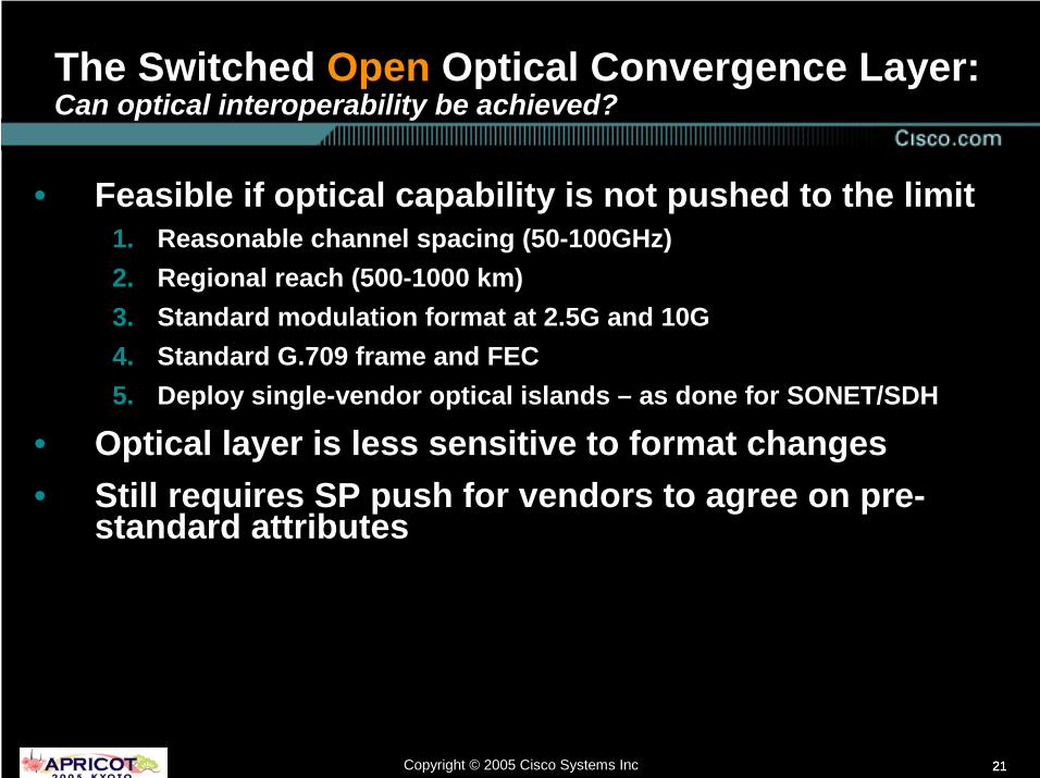
The Switched Open Optical Convergence Layer: Can optical interoperability be achieved?
• Feasible if optical capability is not pushed to the limit1. Reasonable channel spacing (50-100GHz)2. Regional reach (500-1000 km)3. Standard modulation format at 2.5G and 10G4. Standard G.709 frame and FEC5. Deploy single-vendor optical islands – as done for SONET/SDH
• Optical layer is less sensitive to format changes• Still requires SP push for vendors to agree on pre-
standard attributes

222222Copyright © 2005 Cisco Systems Inc
Lambda Networking in Practice
232323Copyright © 2005 Cisco Systems Inc
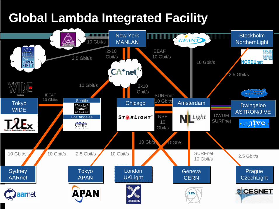
Global Lambda Integrated Facility
DWDM SURFnet
10 Gbit/s
SURFnet10 Gbit/s
SURFnet10 Gbit/s
IEEAF10 Gbit/s
DwingelooASTRON/JIVE
DwingelooASTRON/JIVE
PragueCzechLight
PragueCzechLight
2.5 Gbit/s
NSF10
Gbit/s
LondonUKLightLondonUKLight
StockholmNorthernLightStockholm
NorthernLight
2.5 Gbit/s
New YorkMANLANNew YorkMANLAN
10 Gb/s 10Gb/s
10 Gbit/s
2x10 Gbit/s
IEEAF10 Gbit/s
2x10 Gbit/s
10 Gbit/s
2.5 Gbit/s
2.5 Gbit/s
TokyoAPANTokyoAPAN
GenevaCERN
GenevaCERN
ChicagoChicago AmsterdamAmsterdam
SydneyAARnetSydneyAARnet
10 Gbit/s
10 Gbit/s 10 Gbit/s
SeattleSeattle
Los AngelesLos Angeles
TokyoWIDETokyoWIDE

242424Copyright © 2005 Cisco Systems Inc
7600 km9300 km
17 Time Zones
10 Gbps λ10 Gbps λ
World Longest 10GE connection betweenJapan and CERN, Switzerland
www.icair.org/pr/oct04/gigabit.html

252525Copyright © 2005 Cisco Systems Inc
Lambda Networking Test bed in Korea
Source: KREOnet2

262626Copyright © 2005 Cisco Systems Inc
Thank You!

![MCI (MCI) MCBI (MCI) *MCI FMild Cognitive …...MCI (MCI) MCBI (MCI) *MCI FMild Cognitive Impairment] DZ 1 Y (TTR) MCI Abeta sequester proteins as blood-based biomarkers of cognitive](https://img.dokumen.tips/doc/110x75/5edb546ead6a402d66657e90/mci-mci-mcbi-mci-mci-fmild-cognitive-mci-mci-mcbi-mci-mci-fmild-cognitive.jpg)