Embed Size (px)
Citation preview

New Video Applications on Mobile Communication Devices
Olli Silvena, Jari Hannukselaa, Miguel Bordallo-Lopeza, Markus Turtinenb, Matti Niskanenb,Jani Boutelliera, Markku Vehvilainenc and Marius Ticoc
aMachine Vision Group, University of Oulu, Oulu, FinlandbVisidon Ltd, Oulu, Finland
cNokia Research Center, Tampere, Finland
ABSTRACTThe video applications on mobile communication devices have usually been designed for content creation, access,and playback. For instance, many recent mobile devices replicate the functionalities of portable video camerasand video recorders, and digital TV receivers. These are all demanding uses, but nothing new from the consumerpoint of view. However, many of the current devices have two cameras built in, one for capturing high resolutionimages, and the other for lower, typically VGA (640x480 pixels) resolution video telephony. We employ video toenable new applications and describe four actual solutions implemented on mobile communication devices. Thefirst one is a real-time motion based user interface that can be used for browsing large images or documents suchas maps on small screens. The motion information is extracted from the image sequence captured by the camera.The second solution is a real-time panorama builder, while the third one assembles document panoramas, bothfrom individual video frames. The fourth solution is a real-time face and eye detector. It provides another typeof foundation for motion based user interfaces as knowledge of presence and motion of a human faces in the viewof the camera can be a powerful application enabler.
Keywords: User interaction, camera, motion analysis, panorama construction, face detection
1. INTRODUCTIONModern mobile communication devices are becoming attractive platforms for multimedia applications as theirdisplay and imaging capabilities are improving together with the computational resources. Many of the deviceshave two built-in cameras, one for high resolution still and video imaging, and the other for obtaining lower, e.g.VGA resolution (640x480 pixels) frames. Table 1 points out the versatility of user interfaces of handheld devicesin comparison to laptop computers.1
To illustrate the current typical designs we see two modern cellular phone designs in Fig. 1 below, bothwith two cameras. The flip phone has a high resolution camera on the cover, on the same side with a display.However, it is intended to be operated with the lid open, exposing a higher resolution display, and the user to anadditional camera. The monoblock design is similar to digital still cameras with the high resolution display andcameras on opposite sides. It is obvious that with the display side cameras the designers have aimed at handheld video telephony, while at the same time satisfying the needs for occasional photography, video capture, andplayback.
The usability of mobile communications devices in portable imaging applications is on par with laptopcomputers despite the order of magnitude disparity between the computing power budgets. The sizes andsemi-dedicated user interfaces of the hand-held devices are significant benefits over the general purpose personalcomputer technology based platforms, despite their apparent versatility. On the other hand, even the most recentmobile communication devices have not used their multimedia and computing resources in a novel manner, butare merely replicating the functionalities already provided by other portable devices, such as digital still andvideo cameras. Also the popularity of laptop PCs as portable DVD players, and as a means to access multimediacontent via public WiFi networks, have clearly influenced the hand held application designs. Consequently, mostof the hand held devices rely on keypad-and-pointer user interfaces, while their applications rely on contentprovided via the Internet or broadcast services such as DVB-H, to supplement locally stored music, movies, andmaps. Although the users can create content and stream it to the network for redistribution, and make videocalls, these uses are not very common.
Corresponding author: Olli Silven, E-mail: [email protected], Telephone: +358 8 553 2788
Please verify that (1) all pages are present, (2) all figures are acceptable, (3) all fonts and special characters are correct, and (4) all text and figures fit within themargin lines shown on this review document. Return to your MySPIE ToDo list and approve or disapprove this submission.
6821-7 V. 4 (p.1 of 14) / Color: No / Format: Letter / Date: 1/21/2008 4:55:52 AM
SPIE USE: ____ DB Check, ____ Prod Check, Notes:
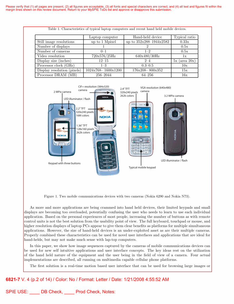
Table 1. Characteristics of typical laptop computers and recent hand held mobile devices.
Laptop computer Hand-held device Typical ratioStill image resolutions up to 1 Mpixel up to 352x288–1944x2582 0.33xNumber of displays 1 2 0.5xNumber of cameras 0–1 1–2 0.5xVideo resolution 720x576/25Hz 640x480/30Hz 1xDisplay size (inches) 12–15 2–4 5x (area 20x)Processor clock (GHz) 1–3 0.3–0.5 10xDisplay resolution (pixels) 1024x768– 1600x1200 176x208– 800x352 15xProcessor DRAM (MB) 256–2044 64–256 16x
CIF+ resolution (384x320)camera
2 MPix camera
Keypad with three buttons
1.36" TFT128x160 pixels262k colors
2.2" TFT320x240 pixels16M colors
LED illuminator / flash
2.4" TFT320x240 pixels262k colors
VGA resolution (640x480)camera
3.2 MPix camera
LED illuminator / flash
Typical mobile keypad
Figure 1. Two mobile communications devices with two cameras (Nokia 6290 and Nokia N73).
As more and more applications are being crammed into hand held devices, their limited keypads and smalldisplays are becoming too overloaded, potentially confusing the user who needs to learn to use each individualapplication. Based on the personal experiences of most people, increasing the number of buttons as with remotecontrol units is not the best solution from the usability point of view. The full keyboard, touchpad or mouse, andhigher resolution displays of laptop PCs appear to give them clear benefits as platforms for multiple simultaneousapplications. However, the size of hand-held devices is an under-exploited asset as are their multiple cameras.Properly combined these characteristics can be used for novel user interfaces and applications that are ideal forhand-helds, but may not make much sense with lap-top computers.
In this paper, we show how image sequences captured by the cameras of mobile communications devices canbe used for new self intuitive applications and user interface concepts. The key ideas rest on the utilizationof the hand held nature of the equipment and the user being in the field of view of a camera. Four actualimplementations are described, all running on multimedia capable cellular phone platforms.
The first solution is a real-time motion based user interface that can be used for browsing large images or
Please verify that (1) all pages are present, (2) all figures are acceptable, (3) all fonts and special characters are correct, and (4) all text and figures fit within themargin lines shown on this review document. Return to your MySPIE ToDo list and approve or disapprove this submission.
6821-7 V. 4 (p.2 of 14) / Color: No / Format: Letter / Date: 1/21/2008 4:55:52 AM
SPIE USE: ____ DB Check, ____ Prod Check, Notes:

documents such as maps on small screens. The motion information of the device itself, the face, or the hand of theuser is extracted from the image sequence. The second solution is a real-time panorama builder, while the thirdone assembles document panoramas; both are from individual video frames based on the motion information.The fourth solution is a real-time face and eye detector that can be used with auto-focusing and red eye reductiontechniques, essentially providing a basis for user interfaces that are aware of the presence of human faces andthe direction of the gaze. When combined, face or limb, and motion information can be powerful applicationenablers and may change the expectations on how hand held devices are supposed to be aware of the user andreact to his/her actions.
In the following, we initially describe the typical platform characteristics of the mobile communication devices,and then proceed to the video based user interface and application solutions. The limitations and the poten-tials of the realizations are analysed against the current state-of-the-art. Finally, the desirable future platformdevelopments are considered from the camera based user interface and application point of view.
2. MOBILE COMMUNICATIONS DEVICE PLATFORMS
A typical top level hardware organization of a mobile communications device with multimedia capability is shownin Fig. 2. Two main interconnects are used for transfers between system units that are partitioned to avoidbottlenecks. The Interconnect 2 provides for high transfer bandwidths between the cameras, memories, andthe video and image processing unit that in turn has high speed local buses between its internal subsystems.Interconnect 1 is the system bus that interfaces the essential units with the master application processor.
Figure 2. Organization of portable multimedia device.
We notice that the application processor has rapid access to the data produced by the camera, so the designis not a simple replacement for a camcorder. Instead, potential for software based image and video applicationshas been engineered into the system architecture. Transfer resources and energy can be conserved if the cameraimages need not to be shown. In contrast, the camcorder mode is rather transfer intensive as it requires real-time encoding and display functions. Video calls are even more complicated as they require the simultaneousoperation of a video encoder, display, and decoder together with both uplink and downlink streaming via thebaseband unit.
The power budgets of the mobile devices are designed and optimized on the basis of the worst case uses.Video applications in their various forms are among the most demanding ones as the users tend to demand long,at least 3-4 hour active use from small devices without connecting to the electrical mains network for rechargingthe battery. As the capacity of the batteries depend on the discharge current in a non-linear manner, relativelysmall cuts in power consumption can significantly extend the battery life.2 Consequently, the manufacturers aretempted to employ hardware accelerators for video due to their power efficiency. For the builders of alternativevideo based applications this can be a blessing, along with the availability of graphics processors.
Table 2 presents power breakdowns of three devices in video playback mode to illustrate the impacts of designphilosophies. The PDA device can be characterized as a scaled down personal computer. The early 3G mobilephone is mostly a communications device with an application processor, while the future device adds hardwarebased video and a GPU to achieve a 3h battery life that is often considered critical in entertainment use. In both
Please verify that (1) all pages are present, (2) all figures are acceptable, (3) all fonts and special characters are correct, and (4) all text and figures fit within themargin lines shown on this review document. Return to your MySPIE ToDo list and approve or disapprove this submission.
6821-7 V. 4 (p.3 of 14) / Color: No / Format: Letter / Date: 1/21/2008 4:55:52 AM
SPIE USE: ____ DB Check, ____ Prod Check, Notes:

cellular devices, the modem and the RF consume a major part of the power budget. Although it is temptingto expect improvements, the future air interfaces are unlikely to use less power as the increasing data ratesand multiple radio protocols are adding to their complexity. Also the miniaturization of RF-components mayactually decrease their power efficiency.
Table 2. Power consumption breakdown examples of pocket sized devices.
System component Power consumption (mW)3G phone in PDA device Expected future
video streaming in MPEG-4 playback mobile devicesmode 3 4
Application processor 600 833 100and memoriesDisplay, audio, keyboard 1000 2441 400and backlights (UI)Misc. memories 200 754 100RF and cellular modem 1200 N/A 1200Total 3000 4028 1800Battery capacity 1000mA/1h N/A 1500mA/3hmAh/usage time
So far a key to improved power efficiency has been in augmenting software solutions with hardware orApplication Specific Instruction-set Processor (ASIP) support for computing intensive tasks. On the other hand,enabling the applications to access the services of these subsystems requires system software architectures andinterfaces that hide the actual nature of the implementations, and the differences between the platforms ofproduct generations. These benefits are not achieved without overheads, but they can be optimized for thetypical expected uses such as streaming video playback. However, any novel uses of the system resources arelikely to encounter the full interface costs.
Table 3 presents the estimated power costs of using the camera for user interface purposes in a mobile device.Three options are considered: first, the only computing resource is the application processor that needs to run atfull speed, second, the system hardware resources such as the GPU and parts of the video codec can be re-usedto conserve power, while the third option is a conventional keypad and display user interface. Obviously, withproper system design the cost of a camera based user interface is reasonable.
Table 3. Estimated power requirement to different types of user interface purposes.
Software based Hardware for Conventional UIcamera UI [mW] camera UI [mW] [mW]
Application processor and memories 600 200 100Display, audio, keypad, backlights 400 400 400Camera (VGA) 50 50 0Misc. memories 100 100 100Total 1150 750 650
As the usability of a user interface critically rests on its latency. This is most obvious with computer gamesin which many perceive joystick action-to-display delays exceeding about 100-150 milliseconds disturbing,5 butthis applies even to key press-to-sound or display. If we employ a camera as a user interface component, itsintegration time will add to the latency, as well as the image analysis computing. If we sample the scene at 15frames/s rate, our base latency is 67 ms. Assuming that the integration time is 33 ms, the information in thepixels read from the camera is on an average 17 ms old. Consequently, computing and display/audio latenciesachieving a total below 100-150 ms reprensent a challenge.
Please verify that (1) all pages are present, (2) all figures are acceptable, (3) all fonts and special characters are correct, and (4) all text and figures fit within themargin lines shown on this review document. Return to your MySPIE ToDo list and approve or disapprove this submission.
6821-7 V. 4 (p.4 of 14) / Color: No / Format: Letter / Date: 1/21/2008 4:55:52 AM
SPIE USE: ____ DB Check, ____ Prod Check, Notes:

Table 4 summarizes the latency budget for two frame rates, 15 and 30 frames/s that are typical of mobiledevices. The integration time of the camera is assumed to be 33 ms at both rates. If the computing is donein a pipeline that contains more than a single processor, the image analysis may effectively be longer than thebase latency. Interestingly, at the lower frame rate less time is available, while on the other hand, the cameraoperated at a higher rate demands more power.
Table 4. Latency budgets for camera based user interfaces at two frame rates.
Component Rate (frames/s)15 30
Base latency (ms) 67 3350 % camera integration time (ms) 17Display latency (ms) 20Image analysis max (ms) 46 80Total max (ms) 150 150
An obstacle to camera based user interfaces is the turn-on time that is not only dependent on the power-updelay of the camera, but is mostly caused by software. The current multimedia frameworks intended for useon mobile platforms have substantial latencies when the resources are reconfigured for the applications. Forinstance, Rintaluoma et al6 found that the Symbian MMF (MultiMedia Framework) consumed approximately60000 processor cycles for accessing a device driver from the application layer. OpenMAX is claimed to be alighter weight interface for use in streaming multimedia hardware and software components. However, it has notso far been intended for user interface purposes. We may find some models on how to proceed from OpenGL ESthat have been designed with an eye on game applications. It is a highly optimized graphics system designed foraccelerators used on embedded and mobile devices.
In addition to the user interfaces, the applications described next provide insight into the computing needs andcharacteristics of camera based user interfaces. If cameras become standard user interface components in mobiledevices, energy efficiency requires that the bulk of the computing is carried out using hardware acceleration.These resources can cause an outgrowth of the current graphics or codec solutions, or both.
3. MOTION BASED USER INTERFACE
The motion based user interface enables a new flexible way of interacting with mobile phones. With thisinterface, the user can operate the phone through a series of hand movements whilst holding the device. Duringthese movements the motion is extracted from the image sequence captured by the camera. As an applicationexample, the solution has been implemented on Nokia Nseries mobile phones, allowing the user to browse largeimage documents on small screens as shown in Fig. 3.
In the application, only a small part of the high resolution image is visible at a time (See Fig. 3 b) andthe measured motion information is used as control input (See Fig. 3 a). For instance, the lateral movementupwards scrolls the focus towards the upper part of the display, and back and forth motion is interpreted aszooming in and out. The rotation component is utilized to change the orientation of the display. In practise, theuser can also tilt the device in order to navigate over the display, which is a more natural and convenient wayof controling the device. Compared to the use of HW accelerometers alone,7 a camera based approach allows amore convenient way of controling zooming effects and adapts better to cases where the user is moving (walkingetc.). A typical use example is illustrated in Fig. 4. The user browses the large image on the small screen of themobile device by moving the device in his hand.
We estimate the ego-motion of the device while the user operates the phone by determining the parametricmodel which approximates the dominant global motion between two images in the sequence captured by thecamera.8 Our approach utilises the feature based motion analysis where a sparse set of blocks are first selectedfrom one image and then their displacements are determined. In order to improve the accuracy of the motioninformation, an uncertainty of these features is also analysed.
Please verify that (1) all pages are present, (2) all figures are acceptable, (3) all fonts and special characters are correct, and (4) all text and figures fit within themargin lines shown on this review document. Return to your MySPIE ToDo list and approve or disapprove this submission.
6821-7 V. 4 (p.5 of 14) / Color: No / Format: Letter / Date: 1/21/2008 4:55:52 AM
SPIE USE: ____ DB Check, ____ Prod Check, Notes:
(a) (b)
Figure 3. Motion based user interface estimates the motion of the device relative to the user enabling also zoomingfunctionalities (a). It can be used, for example, to browse large image documents on the screen (b).
Zooming incommand
Scrolling command
Figure 4. A use example of a motion based user interface.
The main steps of motion estimation are presented in Fig. 5. For details, please see the paper by Hannukselaet al.8 The blocks in the top left present the selected image regions to be used, while the lines in the top rightimage illustrate the block displacement estimates, d, and ellipses show the related uncertainties. The bottom leftimage shows the trusted features that are used for parametric model fitting. In this case, the ellipses illustratethe weight that a particular displacement estimate has in the fitting. By combining the feature selection withuncertainity information, we obtain a very robust motion estimate of the sequence. This information can bedirectly used to estimate the motion of the device in the user’s hand.
We have implemented our method using only fixed-point arithmetic due to the lack of a floating-point unitin most of current devices. The use of integer operations in the inner loops guarantees high performance. Thesolution can also take advantage of the hardware acceleration used with other video processing applications.Acceleration hardware is designed to support the block-based and pixel-level processing tasks that are not effi-ciently handled by the CPU architecture. Typically such hardware contains highly optimised motion estimationinstructions on blocks from 16x16 to 4x4 pixels which are also usual sizes for the blocks in our method.
Please verify that (1) all pages are present, (2) all figures are acceptable, (3) all fonts and special characters are correct, and (4) all text and figures fit within themargin lines shown on this review document. Return to your MySPIE ToDo list and approve or disapprove this submission.
6821-7 V. 4 (p.6 of 14) / Color: No / Format: Letter / Date: 1/21/2008 4:55:52 AM
SPIE USE: ____ DB Check, ____ Prod Check, Notes:

Selected blocks
Estimated motion
Motion features
Trusted features
Figure 5. Example of global motion estimation.
4. PANORAMA BUILDER
The panorama building solution analyses the frames in the video for motion and moving objects, quantifiesthe quality of each frame, and stitches up to 360 degree panoramas from the best available images.9 We havedeveloped a method where the devices are able to stitch images in real time obtaining a result image thatgrows with the frame acquisition.10 The advantage of using on-line panorama building is related to the memoryrequirements that are smaller compared to the saving of all the frames for later usage. Also immediate feedbackand the possibility of reviewing the panorama images is very useful. Three examples are shown in Fig. 6.
Figure 6. Efficient panorama builder stiches high quality images even if there are moving objects in the scene.
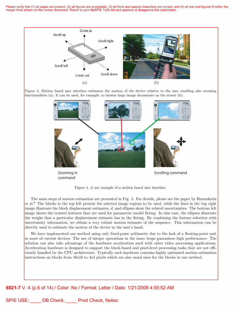
The panorama capturing procedure is illustrated in Fig. 7. In order to get a final panorama image, the userfocuses the camera on the desired starting point of the mosaic. The camera starts turning around up to 360degrees and a sequence of images starts to be captured. Each image is individually processed to estimate the
Please verify that (1) all pages are present, (2) all figures are acceptable, (3) all fonts and special characters are correct, and (4) all text and figures fit within themargin lines shown on this review document. Return to your MySPIE ToDo list and approve or disapprove this submission.
6821-7 V. 4 (p.7 of 14) / Color: No / Format: Letter / Date: 1/21/2008 4:55:52 AM
SPIE USE: ____ DB Check, ____ Prod Check, Notes:
shift and rotation. The blurriness of each picture is measured and moving objects are detected. Based on thequality of each individual frame, a selection process takes place. The idea of selection is to consider only goodquality frames for creating the best possible output. The selection process is shown in Fig. 8. Each frame iseither accepted or discarded. For every selected frame, if a moving object is present and it fits the sub-image, theimage is blended, drawing a seam that is outside the boundaries the object. If only a partial object is present,the part of the frame without the object is the one that is blended.
Figure 7. During the panorama capturing, the user first focuses the device on the desired direction and then turns aroundin order to create a panorama of the view.
Image registration relies on the method of Vandewalle at al.11 that offers shift and rotation estimationthat is robust against blur. Only a fixed square template on the central part of each frame, where the imagequality is better, is used. This square is downscaled by a factor of two, and filtered to allow faster performance,interpolating then the results of the registration estimation.
The amount of motion blur in the frame is computed with summed derivatives.12 The method estimates theimage’s sharpness by summing together the derivates of each row and each column of the overlapping part. Blurcalculation produces one single number that expresses the amount of high-frequency detail in the image. Thevalue is sensible if it is used to compare images: if a certain image Ia acquires a higher result than image Ib, itmeans that Ia has more high-frequency detail than image Ib (implying that both images depict approximatelythe same scene). Usually this means that Ia is a sharper than image Ib, but on some occasions the difference inthe image content distorts the result.
To perform motion detection, the difference between the current frame and the previous frame is computed.The result is a two-dimensional matrix that covers the overlapping area of the two frames. Then, this matrix islow-pass filtered to remove noise and is thresholded against a fixed value to produce a binary motion map. If thebinary image contains a sufficient amount of pixels that are classified as motion, the dimensions of the assumedmoving object are determined statistically. First, the centerpoint of the object is approximated by computing theaverage coordinates of all moving pixels. Second, the standard deviation of coordinates is used to approximatethe dimensions of the object.
Frame selection is performed using the score of the blur measurements and the motion detection. Amongthe set of images that present an overlap with the previous blended frame, only the best frame is selected, whilethe others are discarded. The frame blending happens with the feathering method,13 where a linear functiongradually merges one frame to the next by changing the frames’ weight.
Please verify that (1) all pages are present, (2) all figures are acceptable, (3) all fonts and special characters are correct, and (4) all text and figures fit within themargin lines shown on this review document. Return to your MySPIE ToDo list and approve or disapprove this submission.
6821-7 V. 4 (p.8 of 14) / Color: No / Format: Letter / Date: 1/21/2008 4:55:52 AM
SPIE USE: ____ DB Check, ____ Prod Check, Notes:
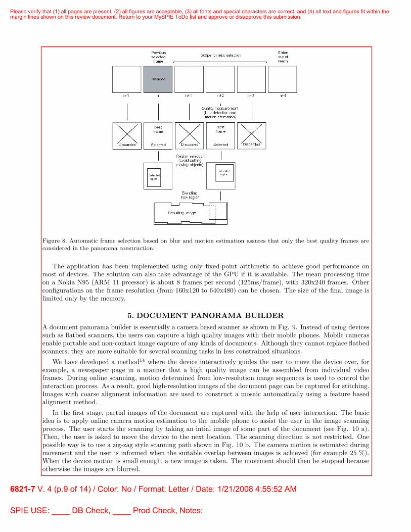
Figure 8. Automatic frame selection based on blur and motion estimation assures that only the best quality frames areconsidered in the panorama construction.
The application has been implemented using only fixed-point arithmetic to achieve good performance onmost of devices. The solution can also take advantage of the GPU if it is available. The mean processing timeon a Nokia N95 (ARM 11 prcessor) is about 8 frames per second (125ms/frame), with 320x240 frames. Otherconfigurations on the frame resolution (from 160x120 to 640x480) can be chosen. The size of the final image islimited only by the memory.
5. DOCUMENT PANORAMA BUILDER
A document panorama builder is essentially a camera based scanner as shown in Fig. 9. Instead of using devicessuch as flatbed scanners, the users can capture a high quality images with their mobile phones. Mobile camerasenable portable and non-contact image capture of any kinds of documents. Although they cannot replace flatbedscanners, they are more suitable for several scanning tasks in less constrained situations.
We have developed a method14 where the device interactively guides the user to move the device over, forexample, a newspaper page in a manner that a high quality image can be assembled from individual videoframes. During online scanning, motion determined from low-resolution image sequences is used to control theinteraction process. As a result, good high-resolution images of the document page can be captured for stitching.Images with coarse alignment information are used to construct a mosaic automatically using a feature basedalignment method.
In the first stage, partial images of the document are captured with the help of user interaction. The basicidea is to apply online camera motion estimation to the mobile phone to assist the user in the image scanningprocess. The user starts the scanning by taking an intial image of some part of the document (see Fig. 10 a).Then, the user is asked to move the device to the next location. The scanning direction is not restricted. Onepossible way is to use a zig-zag style scanning path shown in Fig. 10 b. The camera motion is estimated duringmovement and the user is informed when the suitable overlap between images is achieved (for example 25 %).When the device motion is small enough, a new image is taken. The movement should then be stopped becauseotherwise the images are blurred.
Please verify that (1) all pages are present, (2) all figures are acceptable, (3) all fonts and special characters are correct, and (4) all text and figures fit within themargin lines shown on this review document. Return to your MySPIE ToDo list and approve or disapprove this submission.
6821-7 V. 4 (p.9 of 14) / Color: No / Format: Letter / Date: 1/21/2008 4:55:52 AM
SPIE USE: ____ DB Check, ____ Prod Check, Notes:
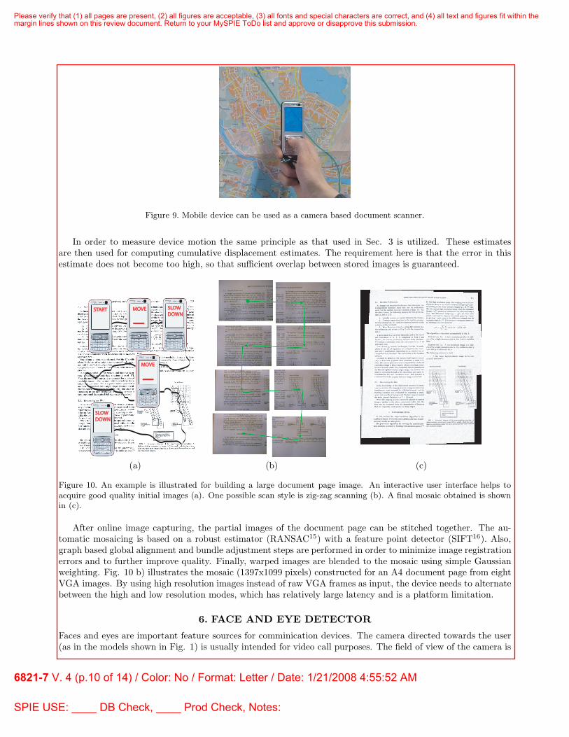
Figure 9. Mobile device can be used as a camera based document scanner.
In order to measure device motion the same principle as that used in Sec. 3 is utilized. These estimatesare then used for computing cumulative displacement estimates. The requirement here is that the error in thisestimate does not become too high, so that sufficient overlap between stored images is guaranteed.
STARTSTART MOVEMOVE SLOWSLOWDOWNDOWN
SLOWSLOWDOWNDOWN
MOVEMOVE
(a) (b) (c)
Figure 10. An example is illustrated for building a large document page image. An interactive user interface helps toacquire good quality initial images (a). One possible scan style is zig-zag scanning (b). A final mosaic obtained is shownin (c).
After online image capturing, the partial images of the document page can be stitched together. The au-tomatic mosaicing is based on a robust estimator (RANSAC15) with a feature point detector (SIFT16). Also,graph based global alignment and bundle adjustment steps are performed in order to minimize image registrationerrors and to further improve quality. Finally, warped images are blended to the mosaic using simple Gaussianweighting. Fig. 10 b) illustrates the mosaic (1397x1099 pixels) constructed for an A4 document page from eightVGA images. By using high resolution images instead of raw VGA frames as input, the device needs to alternatebetween the high and low resolution modes, which has relatively large latency and is a platform limitation.
6. FACE AND EYE DETECTOR
Faces and eyes are important feature sources for comminication devices. The camera directed towards the user(as in the models shown in Fig. 1) is usually intended for video call purposes. The field of view of the camera is
Please verify that (1) all pages are present, (2) all figures are acceptable, (3) all fonts and special characters are correct, and (4) all text and figures fit within themargin lines shown on this review document. Return to your MySPIE ToDo list and approve or disapprove this submission.
6821-7 V. 4 (p.10 of 14) / Color: No / Format: Letter / Date: 1/21/2008 4:55:52 AM
SPIE USE: ____ DB Check, ____ Prod Check, Notes:

optimized for the user’s face regions. This provides advantages for various HCI solutions. In different imagingapplications, the faces are also important. Typically, users are interested in searching for people in the imagesand good quality face regions are among the main concerns in customer imaging. There are already commercialsolutions for different auto focus and auto white balance methods that utilize the detected faces during the imagecapturing. Another examples are smile shutter or other new additional features based on face detection. Thecombined detection of the user’s face and eye has application especially in different user interface solutions wherethe relative position of the user can be obtained via the camera. For example, the knowledge of presence andmotion of a human faces in the view of the camera can be a powerful application enabler.
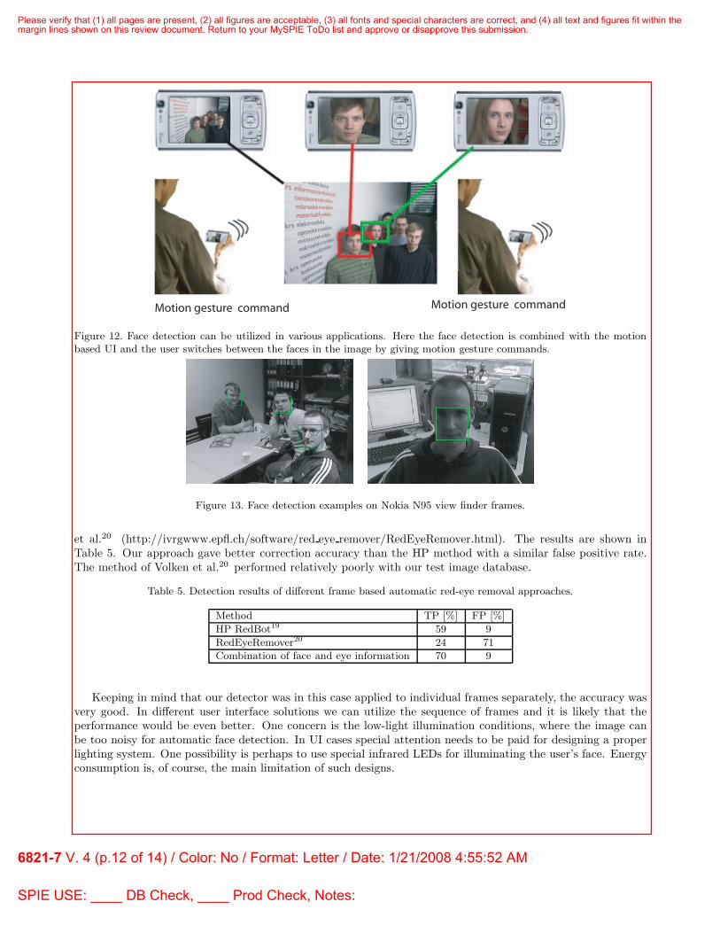
We have built a very fast object detection and tracking method based on efficient gray scale invariant texturefeatures and boosting.17, 18 Our method searches for the faces or eyes in the images or image sequences, andreturns the coordinates of the detected objects. This information can be directly used by face based approaches,such as auto focusing or color enhancement as illustrated in Fig. 11. Another example application is shownin Fig. 12 where the face detection is combined with the motion based UI. The user can give motion gesturecommands to switch the face in the screen. The frontal camera can also observe if the user is actually looking atthe device by estimating the gaze direction with respect to the device. This requires that the face and the eyesare robustly detected in the images.
(a) (b)
Figure 11. Real-time face and eye detection is very useful in various image enhancement applications such as autofocusing(a) and automatic red-eye removal (b).
The algorithm was implemented in the Symbian OS to detect and track a maximum of five objects (faces) inthe images. The demo software processes the QVGA view finder images with a high frame rate, and the detectionperformance is very good, also in demanding illumination conditions. The minimum face size was set to 20×20pixels. We run simulation experiments with the RealView Development Suite using the 180MHz ARM9 CPUand the mean processing time with various image sequences is 68ms/frame (about 15 fps). The face detectionSymbian demo running on a Nokia N95 (ARM11) runs even faster (approximately 26-30 fps). This is fast enoughfor real-time auto focusing or white balancing applications, for example. Fig. 13 shows some example detectionresults. Input QVGA frames are captured by a Nokia N95. The algorithm is robust in varying illuminationconditions and detects very efficiently faces of different sizes and poses.
To demonstrate the detection performance, we built a new kind of automatic red-eye removal solution. Theapproach is frame based where the input image is processed after it has been captured by a high-resolutioncamera. The algorithm automatically finds and corrects the red-eyes caused by the flash light from the images.Face and eye detectors are used to verify each correction to increase the performance of the algorithm. Weexperiment the approach with a set of 393 images having a total of 794 red-eyes. The image set containedtypical home album images of varying quality, having faces and eyes of different sizes and orientations as well.The set also contained specific red-eye images created for testing purpose. Overall, the image set was verydemanding from the automatic red-eye removal point of view. We compared our face and eye detector basedapproach with the dedicated red-eye removal solutions of HP19 (HP RedBot http://www.redbot.net) and Volken
Please verify that (1) all pages are present, (2) all figures are acceptable, (3) all fonts and special characters are correct, and (4) all text and figures fit within themargin lines shown on this review document. Return to your MySPIE ToDo list and approve or disapprove this submission.
6821-7 V. 4 (p.11 of 14) / Color: No / Format: Letter / Date: 1/21/2008 4:55:52 AM
SPIE USE: ____ DB Check, ____ Prod Check, Notes:
Motion gesture command Motion gesture command
Figure 12. Face detection can be utilized in various applications. Here the face detection is combined with the motionbased UI and the user switches between the faces in the image by giving motion gesture commands.
Figure 13. Face detection examples on Nokia N95 view finder frames.
et al.20 (http://ivrgwww.epfl.ch/software/red eye remover/RedEyeRemover.html). The results are shown inTable 5. Our approach gave better correction accuracy than the HP method with a similar false positive rate.The method of Volken et al.20 performed relatively poorly with our test image database.
Table 5. Detection results of different frame based automatic red-eye removal approaches.
Method TP [%] FP [%]
HP RedBot19 59 9
RedEyeRemover20 24 71
Combination of face and eye information 70 9
Keeping in mind that our detector was in this case applied to individual frames separately, the accuracy wasvery good. In different user interface solutions we can utilize the sequence of frames and it is likely that theperformance would be even better. One concern is the low-light illumination conditions, where the image canbe too noisy for automatic face detection. In UI cases special attention needs to be paid for designing a properlighting system. One possibility is perhaps to use special infrared LEDs for illuminating the user’s face. Energyconsumption is, of course, the main limitation of such designs.
Please verify that (1) all pages are present, (2) all figures are acceptable, (3) all fonts and special characters are correct, and (4) all text and figures fit within themargin lines shown on this review document. Return to your MySPIE ToDo list and approve or disapprove this submission.
6821-7 V. 4 (p.12 of 14) / Color: No / Format: Letter / Date: 1/21/2008 4:55:52 AM
SPIE USE: ____ DB Check, ____ Prod Check, Notes:

7. PLATFORM SUPPORT FOR THE NEW VIDEO APPLICATIONS
The development of the demonstration applications has contributed to the identification of features that onmobile platforms would benefit from alternative video applications and camera based user interfaces. We havealso discovered latency and computing bottlenecks tha can be removed via software and hardware developments.
First, it should be possible to use two cameras at the same time or quickly alternate between cameras as imagesources. The motivation for this capability is a practical one: sunlight, lamps, or reflections may saturate oneof the cameras, so the trivial automatic adaptation method is to switch to another image source, although thatmay be a more power consuming high resolution device. However, the current mobile devices have single camerainterfaces, and alternating between cameras requires reconfiguration that may take hundreds of milliseconds.
Second, a stand-by mode for the cameras should exist, perhaps initiated by the handling of the devicerecognized by built-in accelerometers, to reduce the start-up latency of the vision based user interfaces. In thestand-by mode, the camera could capture images, say, at the rate of a frame per second, adjusting to the ambientillumination. The miniature VGA camera modules used in mobile devices require about 1-1.5 mW/frame/s, a costthat needs to be weighted against the gained benefits. The cold start power-up latencies of the camera hardwaremodules alone are around 100ms. At least two images are needed to determine the first motion estimates even ifno gain correction is needed to bring the image information into the useful dynamic region. These plain hardwaredependent delays in total amount to 150-200ms, but would be only 50-100ms from stand-by.
Third, the data formats of the camera and GPU/display units should be compatible and for a number of imageprocessing functions, such as interpolations and warps, it is desirable to use the GPU as a hardware accelerator.The OpenGL interface is highly efficient, but the necessary format changes result in needless copying of data,resulting in reduced energy efficiency, increased computational burden, and latency.
Finally, motion estimation and face detection are potential platform level services to be offered via multimediaAPIs. They play key roles in the demonstrated applications, and are most likely to be employed in manyothers. Implementing them in the camera modules, or the camera interfaces, would reduce the power hungrydata transfers over the system interconnects. Furthermore, distributing the computational load to processingresources tightly coupled to the sensors could result in lower latency.
8. SUMMARY
In the cases presented above, the cameras of multimedia capable mobile devices are employed as motion andfeature sensors in user interface and imaging applications. Motion information coupled with image qualityinformation helps in implementing panorama capture solutions, and is a self-intuitive means of interacting witha small screen and minimal keypad. Face detection from images and image sequences is an exceptionally powerfuluser interface componen, as the user is almost invariably looking at the device. Also the big resolution disparitiesbetween the cameras and displays have generated a need to conveniently browse through the salient informationin the images, usually human faces.
The general approach, extraction of motion and features from sequential video frames, has clear usabilitypotential, and it can augment the information provided by accelerometers and touchscreens in a complementarymanner. In fact, the cameras in future mobile devices may for, the most of time, be used for sensory purposesrather than capturing images for human viewing.
Energy efficiency is a significant challenge in exploiting camera based user interface ideas, but according toour judgment a solvable one. Camera sub-systems on mobile device platforms are a rather recent add-on, anddesigned just for capturing still and video frames, considering the latter as a performance problem. At the sametime the energy efficiency features of the platform architectures, computing resources, and displays have beenoptimized for video playback. From the point of view of the demonstrated panorama applications, compatibledata formats for the camera and graphics systems would be a major improvement. For motion and face baseduser interfaces lower camera start-up latencies would improve the usability, but require careful balancing withenergy efficiency demands.
Please verify that (1) all pages are present, (2) all figures are acceptable, (3) all fonts and special characters are correct, and (4) all text and figures fit within themargin lines shown on this review document. Return to your MySPIE ToDo list and approve or disapprove this submission.
6821-7 V. 4 (p.13 of 14) / Color: No / Format: Letter / Date: 1/21/2008 4:55:52 AM
SPIE USE: ____ DB Check, ____ Prod Check, Notes:
ACKNOWLEDGMENTS
The financial support provided by TEKES, The National Technology Agency is gratefully acknowledged. Wealso want to thank Mr Gordon Roberts for the language revision.
REFERENCES[1] O. Silven and T. Rintaluoma, “Energy efficiency of video decoder implementations,” in F. Fitzek and
F. Reichert (eds.) Mobile Phone Programming and its Applications to Wireless Networking, pp. 421–439,Springer, 2007.
[2] D. Rakhmatov, S. Vrudhula, and D. Wallach, “A model for battery lifetime analysis for organizing applica-tions on a pocket computer,” Very Large Scale Integration (VLSI) Systems 11(6), pp. 1019–1030, 2003.
[3] Y. Neuvo, “Cellular phones as embedded systems,” in Solid-State Circuits Conference, 1, pp. 32–37, 2004.[4] H. Shim, System-Level Power Reduction Techniques for Color TFT Liquid Crystal Displays. PhD thesis,
School of Computer Science and Engineering, Seoul National University, Korea, 2006.[5] J. Dabrowski and E. Munson, “Is 100 milliseconds too fast?,” in Conference on Human Factors in Computing
Systems, pp. 317–318, 2001.[6] T. Rintaluoma, O. Silven, and J. Raekallio, “Interface overheads in embedded multimedia software,”
in International Conference on Embedded Computer Systems: Architectures, Modeling, and Simulation,4017/2006, pp. 5–14, 2006.
[7] P. Eslambolchilar and R. Murray-Smith, “Tilt-based automatic zooming and scaling in mobile devices astate-space implementation,” in Mobile Human-Computer Interaction MobileHCI 2004, pp. 120–131, 2004.
[8] J. Hannuksela, P. Sangi, and J. Heikkila, “Vision-based motion estimation for interaction with mobiledevices,” Computer Vision and Image Understanding: Special Issue on Vision for Human-Computer Inter-action 108(1–2), pp. 188–195, 2007.
[9] J. Boutellier, M. Bordallo-Lopez, O. Silven, M. Tico, and M. Vehvilainen, “Creating panoramas on mobilephones,” in Proceeding of SPIE Electronic Imaging 2007, 6498, (7), 2007.
[10] M. Bordallo-Lopez, J. Boutellier, and O. Silven, “Implementing mosaic stitching on mobile phones,” inFinnish Signal Processing Symposium, 2007.
[11] P. Vandewalle, S. Susstrunk, and M. Vetterli, “A frequency domain approach to registration of aliasedimages with application to super-resolution,” EURASIP Journal on Applied Signal Processing (special issueon Super-resolution) 24, pp. 1–14, 2006.
[12] J. Liang, D. DeMenthon, and D. Doermann, “Camera-based document image mosaicing,” in InternationalConference on Pattern Recognition, pp. 476–479, 2006.
[13] R. Szeliski, “Video mosaics for virtual environments,” in IEEE Computer Graphics & Applications, pp. 22–30, 1996.
[14] J. Hannuksela, P. Sangi, J. Heikkila, X. Liu, and D. Doermann, “Document image mosaicing with mobilephones,” in 14th International Conference on Image Analysis and Processing, pp. 575–580, 2007.
[15] M. A. Fischler and R. C. Bolles, “Random sample consensus: a paradigm for model fitting with applicationsto image analysis and automated cartography,” Communications ACM 24, pp. 381–395, 1981.
[16] D. Lowe, “Distinctive image feature from scale-invariant keypoints,” International Journal of ComputerVision 60(2), pp. 91–110, 2004.
[17] T. Ojala, M. Pietikainen, and T. Maenpaa, “Multiresolution gray-scale and rotation invariant texture classi-fication with local binary patterns,” IEEE Transactions on Pattern Analysis and Machine Intelligence 24(7),pp. 971–987, 2002.
[18] A. Hadid, G. Zhao, T. Ahonen, and M. Pietikainen, “Face analysis using local binary patterns,” in Handbookof Texture Analysis, M. Mirmehdi, ed., Imperial College Press, 2007.
[19] H. Luo, J. Yen, and D. Tretter, “An efficient automatic redeye detection and correction algorithm,” inProceedings of the 17th International Conference on Pattern Recognition (ICPR), 2, pp. 883–886, 2004.
[20] F. Volken, J. Terrier, and P. Vandewalle, “Automatic red-eye removal based on sclera and skin tone detec-tion,” in IS&T Third European Conference on Color in Graphics, Imaging and Vision (CGIV), 2, pp. 359–364, 2006.
Please verify that (1) all pages are present, (2) all figures are acceptable, (3) all fonts and special characters are correct, and (4) all text and figures fit within themargin lines shown on this review document. Return to your MySPIE ToDo list and approve or disapprove this submission.
6821-7 V. 4 (p.14 of 14) / Color: No / Format: Letter / Date: 1/21/2008 4:55:52 AM
SPIE USE: ____ DB Check, ____ Prod Check, Notes: