Embed Size (px)
Citation preview
New Type of Linear Switched Reluctance Generator for Wave Energy Applications
L. García-Tabarés, M. Lafoz, M. Blanco, J. Torres, D. Obradors, J. Nájera, G. Navarro,
CIEMAT
F. García, A. Sánchez
WEDGE GLOBAL
GOBIERNO
DE ESPAÑA
MINISTERIO
DE CIENCIA, INNOVACIÓN
Y UNIVERSIDADESCentro de Investigaciones
Energéticas, Medioambientales
y Tecnológicas

This project has received funding from the European Union’s Horizon 2020 research and innovation programme under grant agreement No. 764014
The World of Wave Energy Converters
UNDIGEN
Wedge Global (ES)
Point Absorber
Attenuator
This project has received funding from the European Union’s Horizon 2020 research and innovation programme under grant agreement No. 764014
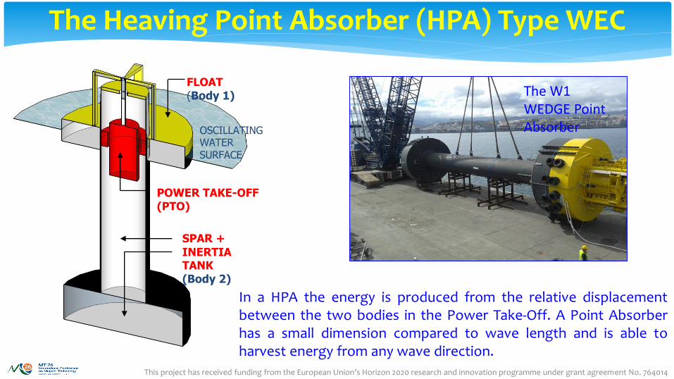
The Heaving Point Absorber (HPA) Type WEC
FLOAT(Body 1)
SPAR +
INERTIA TANK(Body 2)
POWER TAKE-OFF (PTO)
OSCILLATING WATERSURFACE
In a HPA the energy is produced from the relative displacementbetween the two bodies in the Power Take-Off. A Point Absorberhas a small dimension compared to wave length and is able toharvest energy from any wave direction.
The W1 WEDGE Point Absorber
This project has received funding from the European Union’s Horizon 2020 research and innovation programme under grant agreement No. 764014
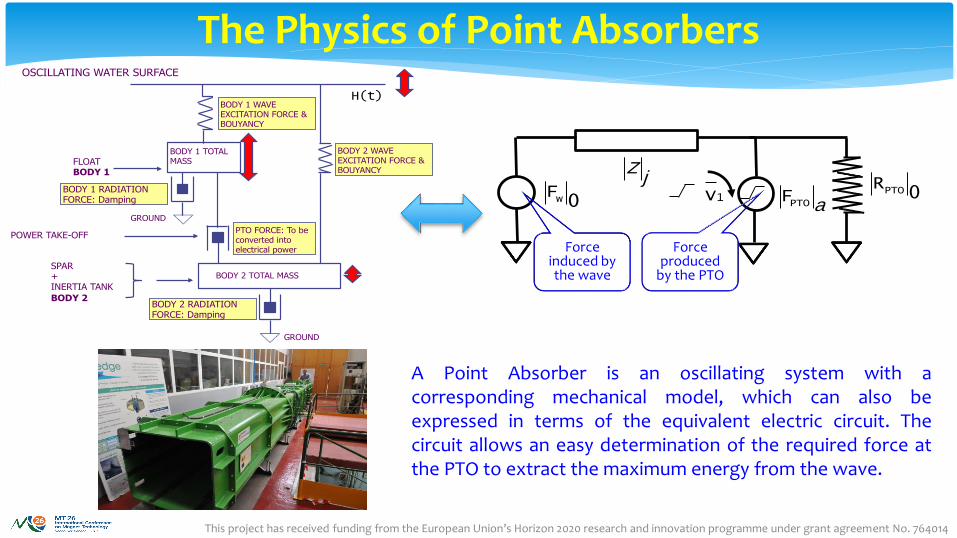
The Physics of Point Absorbers
FLOAT BODY 1
SPAR + INERTIA TANK
BODY 2
POWER TAKE-OFF
H(t)
OSCILLATING WATER SURFACE
BODY 1 WAVE EXCITATION FORCE & BOUYANCY
BODY 1 RADIATION FORCE: Damping
BODY 2 WAVE EXCITATION FORCE & BOUYANCY
BODY 2 RADIATION FORCE: Damping
PTO FORCE: To be converted into electrical power
BODY 1 TOTAL MASS
BODY 2 TOTAL MASS
GROUND
GROUND
Fw 0 FPTO a
Zj
v1RPTO 0
Force induced by the wave
Force produced
by the PTO
A Point Absorber is an oscillating system with acorresponding mechanical model, which can also beexpressed in terms of the equivalent electric circuit. Thecircuit allows an easy determination of the required force atthe PTO to extract the maximum energy from the wave.
This project has received funding from the European Union’s Horizon 2020 research and innovation programme under grant agreement No. 764014
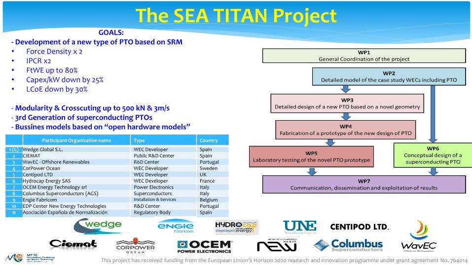
GOALS: - Development of a new type of PTO based on SRM• Force Density x 2• IPCR x2• FtWE up to 80%• Capex/kW down by 25%• LCoE down by 30%
- Modularity & Crosscuting up to 500 kN & 3m/s- 3rd Generation of superconducting PTOs- Bussines models based on “open hardware models”
Participant Organization name Type Country
1 (C) Wedge Global S.L. WEC Developer Spain2 CIEMAT Pubilc R&D Center Spain3 WavEC - Offshore Renewables R6D Center Portugal4 CorPower Ocean WEC Developer Sweden5 Centipod LTD WEC Developer UK6 Hydrocap Energy SAS WEC Developer France7 OCEM Energy Technology srl Power Electronics Italy8 Columbus Superconductors (AGS) Superconductors Italy9 Engie Fabricom Installation & Services Belgium10 EDP Center New Energy Technologies R&D Center Portugal11 Asociación Española de Normalización Regulatory Body Spain
CENTIPOD LTD.
The SEA TITAN Project
This project has received funding from the European Union’s Horizon 2020 research and innovation programme under grant agreement No. 764014
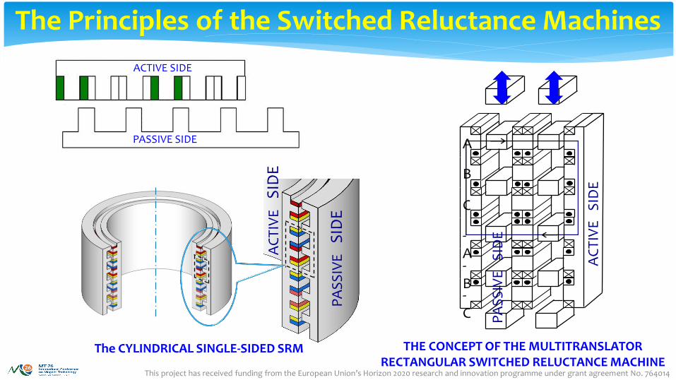
The Principles of the Switched Reluctance Machines
ACTIVE SIDE
PASSIVE SIDE
THE CONCEPT OF THE MULTITRANSLATOR RECTANGULAR SWITCHED RELUCTANCE MACHINE
AC
TIV
ES
IDE
PA
SS
IVE
SID
EThe CYLINDRICAL SINGLE-SIDED SRM
A
B
C
-A-B-C
AC
TIV
E
SID
E
PA
SS
IVE
S
IDE
This project has received funding from the European Union’s Horizon 2020 research and innovation programme under grant agreement No. 764014
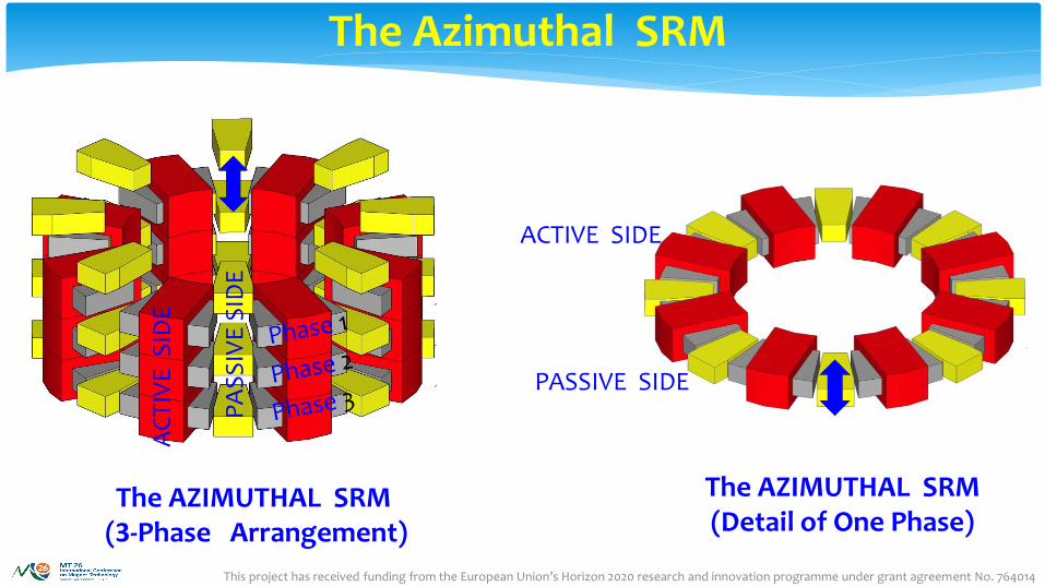
The Azimuthal SRM
PASSIVE SIDE
ACTIVE SIDE
The AZIMUTHAL SRM (Detail of One Phase)
AC
TIV
E S
IDE
PA
SS
IVE
SID
E
The AZIMUTHAL SRM(3-Phase Arrangement)
This project has received funding from the European Union’s Horizon 2020 research and innovation programme under grant agreement No. 764014
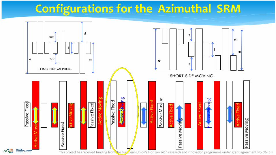
Configurations for the Azimuthal SRM
Pas
sive
Fix
ed
Act
ive
Mo
vin
g
Pas
sive
Fix
ed
Act
ive
Mo
vin
g
Act
ive
Mo
vin
g
Pas
sive
Fix
ed
Pas
sive
Fix
ed
Act
ive
Mo
vin
g
Pas
sive
Mo
vin
g
Act
ive
Fix
ed
Act
ive
Fix
ed
Pas
sive
Mo
vin
g
Pas
sive
Mo
vin
g
Act
ive
Fix
ed
Act
ive
Fix
ed
Pas
sive
Mo
vin
g
s/2
l
e
d
LONG SIDE MOVING
ms/2
s
s
l
e
d
SHORT SIDE MOVING
m
This project has received funding from the European Union’s Horizon 2020 research and innovation programme under grant agreement No. 764014
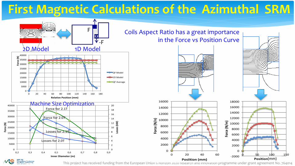
First Magnetic Calculations of the Azimuthal SRM
F
-F2D Model 1D Model
Coils Aspect Ratio has a great importance in the Force vs Position Curve
0
5000
10000
15000
20000
25000
30000
35000
40000
0 20 40 60 80 100 120 140 160 180
Force(N)
RelativePosition(mm)
QFModel
1DModel
QFAverage
0
2
4
6
8
10
12
14
16
18
20
0
5000
10000
15000
20000
25000
30000
35000
40000
0,2 0,3 0,4 0,5 0,6 0,7 0,8 0,9
Losses(k
W)
Force(N)
InnerDiameter(m)
FB2.0T
FB2.1T
PB2.0T
FP2.1T
Forcefor2.1T
Forcefor2.0T
Lossesfor2.1T
Lossesfor2.0T
Machine Size Optimization
0
2000
4000
6000
8000
10000
12000
14000
16000
0 20 40 60Force(N/n)
Posiition(mm)
1.8T
2.0T
2.1T
-2000
0
2000
4000
6000
8000
10000
12000
14000
16000
18000
0 50 100 150
Force(N/m
)
Position(m)
1.8T
2.0T
2.1T
(mm)
This project has received funding from the European Union’s Horizon 2020 research and innovation programme under grant agreement No. 764014
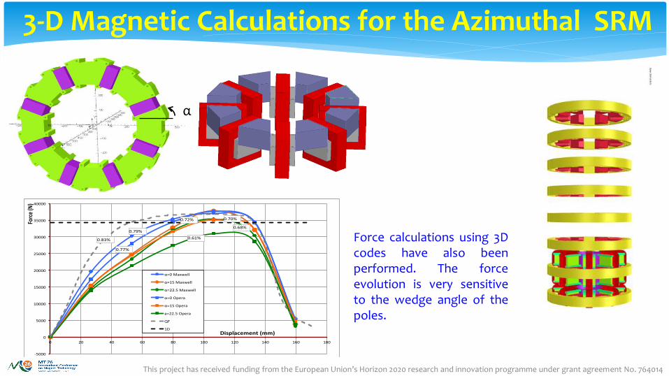
3-D Magnetic Calculations for the Azimuthal SRM
α
-5000
0
5000
10000
15000
20000
25000
30000
35000
40000
0 20 40 60 80 100 120 140 160 180
Force(N)
Displacement(mm)
α=0Maxwell
α=15Maxwell
α=22.5Maxwell
α=0Opera
α=15Opera
a=22.5Opera
QF
1D
0.79%
0.77%
0.72% 0.70%
0.68%
0.61%0.83% Force calculations using 3Dcodes have also beenperformed. The forceevolution is very sensitiveto the wedge angle of thepoles.
This project has received funding from the European Union’s Horizon 2020 research and innovation programme under grant agreement No. 764014
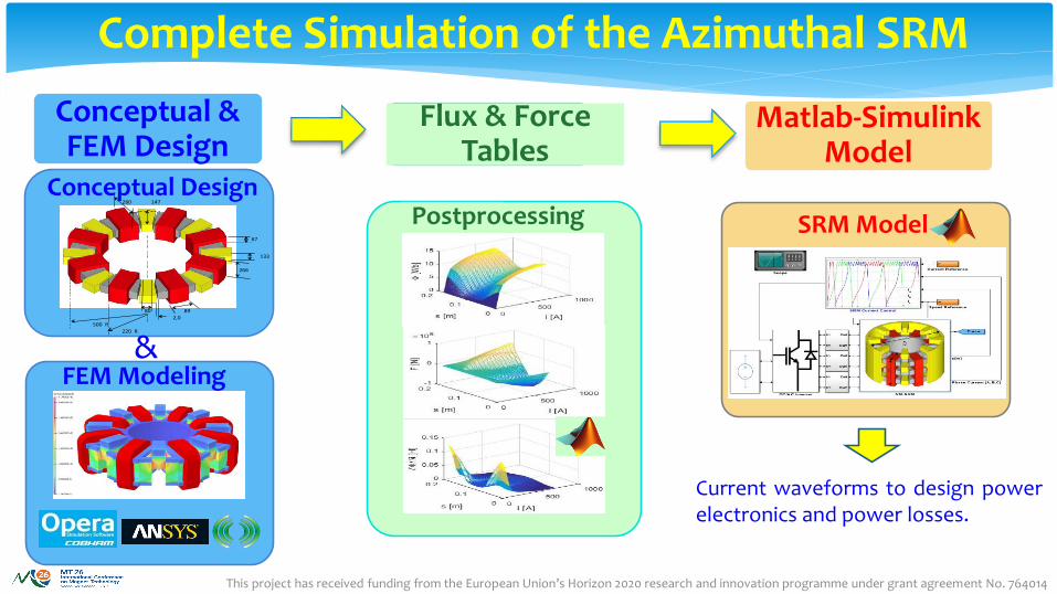
Current waveforms to design powerelectronics and power losses.
Flux & ForceTables
Postprocessing
Matlab-Simulink Model
SRM Model
Complete Simulation of the Azimuthal SRM
280 147
133
266
80 892,0
500 R220 R
67
Conceptual Design
FEM Modeling
Conceptual & FEM Design
&
This project has received funding from the European Union’s Horizon 2020 research and innovation programme under grant agreement No. 764014
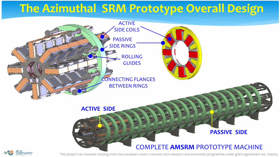
COMPLETE AMSRM PROTOTYPE MACHINE
ACTIVE SIDE
PASSIVE SIDE
The Azimuthal SRM Prototype Overall DesignACTIVE
SIDE COILS
PASSIVESIDE RINGS
CONNECTING FLANGES BETWEEN RINGS
ROLLING GUIDES
This project has received funding from the European Union’s Horizon 2020 research and innovation programme under grant agreement No. 764014
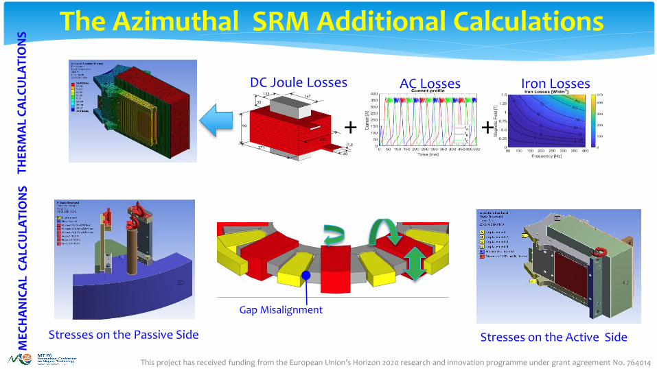
The Azimuthal SRM Additional Calculations
133 147
90
1,5
60
257
271
32
DC Joule Losses AC Losses Iron Losses
TH
ER
MA
L C
ALC
ULA
TIO
NS
++
ME
CH
AN
ICA
L C
ALC
ULA
TIO
NS
Gap Misalignment
Stresses on the Passive Side Stresses on the Active Side
This project has received funding from the European Union’s Horizon 2020 research and innovation programme under grant agreement No. 764014
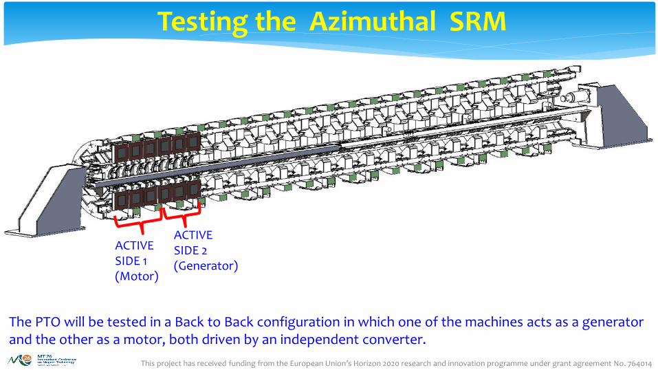
Testing the Azimuthal SRM
ACTIVESIDE 2(Generator)
ACTIVESIDE 1(Motor)
The PTO will be tested in a Back to Back configuration in which one of the machines acts as a generator and the other as a motor, both driven by an independent converter.
This project has received funding from the European Union’s Horizon 2020 research and innovation programme under grant agreement No. 764014
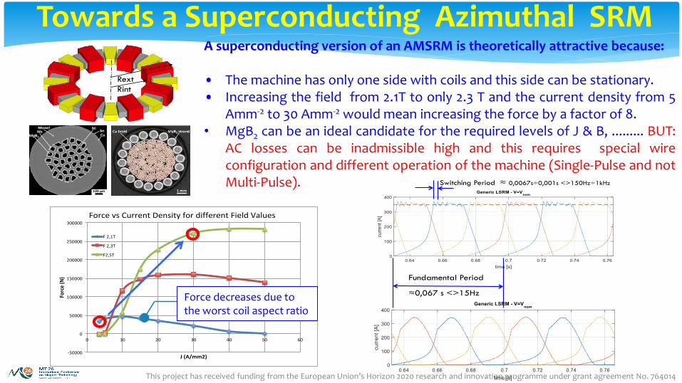
Towards a Superconducting Azimuthal SRM
Rext Rint
A superconducting version of an AMSRM is theoretically attractive because:
• The machine has only one side with coils and this side can be stationary.• Increasing the field from 2.1T to only 2.3 T and the current density from 5
Amm-2 to 30 Amm-2 would mean increasing the force by a factor of 8.• MgB2 can be an ideal candidate for the required levels of J & B, ......... BUT:
AC losses can be inadmissible high and this requires special wireconfiguration and different operation of the machine (Single-Pulse and notMulti-Pulse).
-50000
0
50000
100000
150000
200000
250000
300000
0 10 20 30 40 50 60
Force(N)
J(A/mm2)
ForcevsCurrentDensityfordifferentFieldValues
F2,1T
F2,3T
F2,5T
Force decreases due to the worst coil aspect ratio
Fundamental Period
≈0,067 s <>15Hz
Switching Period ≈ 0,0067s÷0,001s <>150Hz÷1kHz
This project has received funding from the European Union’s Horizon 2020 research and innovation programme under grant agreement No. 764014
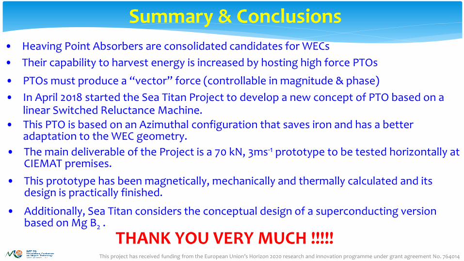
• Heaving Point Absorbers are consolidated candidates for WECs
• Their capability to harvest energy is increased by hosting high force PTOs
• PTOs must produce a “vector” force (controllable in magnitude & phase)
• In April 2018 started the Sea Titan Project to develop a new concept of PTO based on a linear Switched Reluctance Machine.
• This PTO is based on an Azimuthal configuration that saves iron and has a better adaptation to the WEC geometry.
• The main deliverable of the Project is a 70 kN, 3ms-1 prototype to be tested horizontally at CIEMAT premises.
• This prototype has been magnetically, mechanically and thermally calculated and its design is practically finished.
• Additionally, Sea Titan considers the conceptual design of a superconducting version based on Mg B2 .
Summary & Conclusions
THANK YOU VERY MUCH !!!!!