Embed Size (px)
Citation preview

Engineering
Electrical Engineering fields
Okayama University Year 1996
New trends in active filters for improving
power quality
Hirofumi AkagiOkayama University
This paper is posted at eScholarship@OUDIR : Okayama University Digital InformationRepository.
http://escholarship.lib.okayama-u.ac.jp/electrical engineering/62

New Trends in Active Filters for Improving Power Quality
harmonic pollution
Hirofumi Akagi, Senior Member, IEEE Department of Electrical Engineering
Okayama University Okayama-city, 700 Japan
air poll+5n
I c
Ab8truct- Since their basic compensation principles were proposed around 1970, active filters have been studied by many researchers and engineers aiming to put them into practical applications. Shunt active filters for harmonic compensation with or without reactive power compensation, flicker compensation or voltage regulation have been put on a commercial base in Japan, and their rating or capacity has ranged from BOkVA to BOMVA at present. In near fu- ture, the term of active filters will cover a much wider sense than that of active filters in the 1970's did. The function of active filters will be expanded from voltage flicker compen- sation or voltage regulation into power quality improvement for power distribution systems as the capacity of active fil- ters becomes larger. This paper describes present states of the ackive filters based on state-of-the-art power electron- ics technology, and their future prospects toward the 2lst century, including the personal view and expectation of the author.
I. INTRODUCTION
A number of low-power electronic-based appliances such as TV sets, personal computers, and adjustable speed heat pumps generate a large amount of harmonic current in power systems even though a single low-power electronic- based appliance, in which a single-phase diode rectifier with a dc link capacitor is used as utility interface, produces a negligible amount of harmonic current. Three-phase diode or thyristor rectifiers and cycloconverters for industry a p plications. also generate a large amount of harmonic cur- rent. Voltage distortion or harmonics resulting from cur- rent harmonics produced by power electronic equipment has become a serious problem to be solved in many coun- tries.
The guidelines for harmonic mitigation, announced on Oct. 3, 1994 in Japan, are currently applied on a voluntary basis to keep harmonic levels in check and promote be& ter practices in both power systems and equipment design. In general, individual low-power end-users and high-power consumers are responsible for limiting the current harmon- ics caused by power electronic equipment, while electric power companies are responsible for limiting voltage har- monics at the point of common coupling in power trans- mission and distribution systems.
Since the basic principles of active filters were proposed around 1970, attention has been paid to active filters [I]- [6]. The advance of power electronics technology over the last ten years, along with the theory of instantaneous ac- tive and reactive power in three-phase circuits which was presented ill 1983 [8], has made it possible to put active filters into practical applications, not only for harmonic compensation with or without reactive power compensa-
TABLE I ANALOGY BETWEEN HARMONIC POLLUTION AND AIR POLLUTION
unidentiEed
identified L e TV sets, and per-
sonal computers
adjustable speed heat pumps
0 bulk rectifiers
e cycloconverters
e arc furnaces
gasdinefueled
a diesel-powered vehicles
e chemicaiphts 0 coal and oil steam power stations
tion [7][11], but also for flicker compensation [12] and volt- age regulation of impact drop at the end terminai of a power system servicing the Shinkansen, i.e., the Japanese '*bullet" trains [33][34]. Nowadays, more than three hun- dred shunt active filters consisting of voltage-fed PWM in- verters using IGBTs or GTG thyristors are operating prop erly in Japan, the capacity or rating of which ranges from 50kVA to GOMVA. ,411 of them have bexi installed by in- dividual high-power consumers on their 0" premises near harmonic-producing loads. The shunt active filters have presented much more satisfackory filtering characteristies than conventional shunt passive filters and/or static var compensators based on thyristor-controlled reactors.
This paper deals with present states and new trends in active filters for improving power quality of industrial plants and distribution systems. First of all, the latest measured results of voltage harmonics in a power system in Japan are shown every voltage class. Then, clwificai tion of active filters is made from their objectives, system configurations, power circuits, and control strategy. Next, a couple of interesting examples of practical applications of active filters are presented with their capacity and objec- tive. Finally, their future prospects toward the 21st century are described with the focus on active filters for damping of harmonic propagation or resonance rather than for har- monic compensation, which will be dispersively installed on power distribution systems by electric power companies.
11. VOLTAGE HARMONICS IN POWER SYSTEMS
A . Harmonic-Producing Loads
Nonlinear loads drawing non-sinusoidal currents from electric utilities are classified into identified and uniden- tified loads by whether electric utility companies can iden-
- 0-7803-2795-0 417

TABLE I1 VOLTAGE HARMONICS IN A POWER SYSTEM
TABLE 111 VOLTAGE HARMONICS IN A DISTRIBUTION SYSTEM OF 6.6KV
tify the point and capacity of harmonic-producing loads on distribution systems. Large capacity diode or thyristor rec- tifiers, cycloconverters, and arc furnaces installed by high- and mediumvoltage consumers are typical identified har- monic-producing loads.
On the other hand, singlephase diode rectifiers with dc link capacitors are representative unidentified harmonic- producing loads, which have been widely used as utility interface in TV sets, personal computers, and so on. Al- though a-singlephase diode rectifier generates a negligible amount of harmonic current, the total amount of harmonic current procliiced by all the singlephase diode rectifiers has become dominant rather than non-negligible in power dis- tribution systems at present. No one has paid attention
monic-producing loads except for some and engineers in power electronics and
power engineering, so that the guidelines or regulations for harmonic mitigation would play an important role. Table 1 shows an interesting analogy in unidentified and identified sources between harmonic contamination and air pollution.
8. Voltage Harmonics
Tables 2 and 3 show maximum and minimum values of total harmonic distortion (THD) and voltage harmonics in a typical power in Japan, which were memured from April 28 to 1994 [31]. The total harmonic distortion and voltage harmonics in the high-voltage power
Power System in Japan
Shunt Active Filter
system tend to be less than those in distribution system of 6.6kV. The reas of short circuit capacity, which Fesults and interlinkage of high-voltage power systems, has made high-volatge systems more stiff. As system, the maximum value of the 5t a residential area exceeds its allowabl of the total hasmonic distortion level of 5%. Table 3 suggests that dominant harmonic-pro- ducing loads in residential areas of dist ‘(unidentified” electroniobased appli
ters have been have been proposed. Classification of active filters is made from different points of view. Active filters are divided into
many cases at present.
into two types of active filters. One is active filters which have already been installed by individual electric power

consumers on their own premisis near one or more identified harmonioproducing bads. Another is active filters which will be installed by electric power utilities on their own substations and/or distribution feeders.
The purpose of active filters installed by electric con- sumers is to compensate for current harmonics, current un- balance or negativesequence currents, and voltage flickers. On the other hand, the purpose of active filters installed by electric utilities would be to compensate for voltage har- monim at the point of common coupling in distribution systems, and to damp harmonic propagation caused by resonace between line inductors including leakage induc- tances of distribution transformers tiad shunt capacitors for improving power factw in power systems.
B. Classification from System Configurations
B.1 Shunt active filters and series active filters
Fig.1 shows a system configuration of a shunt active fil- ter standing alone, which is one of the most basic system configurations. The shunt active filter injects a compen- sating current into the supply to cancel current harmonics contained on the ac side of a general-purpose thyristor rec- tifier with a dc link inductor [15][16] or a PWM rectifier with a dc link capacitor for traction systems [30]. The shunt active filter has the capability of damping harmonic propagation between an already-existing passive filter and the supply impedance [11][27]. Fig.2 shows a system con- figuration of a series active filter standing alone. The series active filter is connected in series with the supply through a matching transformer, so that it is applicable to harmonic compensation for a large capacity diode rectifier with a dc link capacitor. Table 4 shows comparisons between the shunt and series active filters. This concludes that the se- ries active filter has a “dual” relationship in each item with the shunt active filter [23].
B.2 Hybrid active and passive filters
Figs.3, 4 and 5 show three types of hybrid active and passive filters, the major purpose of which is to reduce initial costs and to imprwe efficiency.
The shun’; passive filter consists of one OF more tuned LC filters and/or a high-pass filter. Table 5 shows comparisons among the three hybrid filters, in which the active filters are different in function from the passive filters. The com- bination of shunt active and passive filters has already been applied to harmonic compensation for large capacity cyclo- converters for steel mill drives [ll]. The combined filters, shown in Fig.4 [18] [24] [37] and in Fig.5 I201 [29] [36], will be practically applied in near future, considered prospective alternatives to shunt or series active filters standing alone. Other combined systems of active filters and passive filters or LC circuits have been proposed in [28][32].
B.3 Combination of shunt active filters and series active
Fig.6 shows the combination of a shunt active filter and a series active filter [14][38][39]. The major purpose of the
J -
filters
Thyristor Rectifier l-7-m-l
U r--t
$Shunt P y j ; h U I Filter
Shunt Active Filter
Fig. 3. Combination of shunt a i v e filter and shunt passive filter
Thyristor Rectifier
@ Filter f u n t passive
Series Active Filter Fig. 4. Combination of Series active filter and shunt passive filter
Thyristor Rectifier -
I Shunt Passive
ER+-+ U
Series Active Filter
Fig. 5. Active filter connected in series with shunt passive filter
series active filter is harmonic isolation between the s u b transmission system and ’the distribution system, and volt- age regulation as well as voltage flicker and/or imbalance compensation at the point of common coupling (PCC). The main purpose of the shunt active filter is harmonic sink, r e active power compensation and dc link voltage regulation between both active filters.
An example of a basic unified power quality conditioner having the only function of harmonic compensation is taken in the following. The series active filter, which keeps har- monic currents from flowing in and out of the distribution feeders, is controlled to present zero impedance for the fun- damental frequency and to act as a resistor with high r e sistance of G [a] for the harmonic frequencies [18]
VAF = G , ish.
The shunt active filter, which absorbs harmonic currents generated from the feeders, is controlled to present high impedance for the fundamental frequency and to act as a resistor with low resistance of 1/K [L?] for the harmonic frequencies.
~ A F = K * VSh.
( 1)
(2)
!
41 9

TABLE IY COMPARISON OF SHUNT AND SERIFS ACTIVE FIETERS STANDING ALONE
TABLE V COMPARISON OF HYBRID ACTNE AND PASSIVE PILTERS
shunt active filter plus shunt series active filter plus shunt series actbe filter connected in passive filter passive filter series with shunt passive filter
system configuration Figure 3 Figure 4 Figure 5
e voltage-fed PWM inverter e voltage-fd PWM invertet without current minor loop
e vO1taefed pwM inverter with or without current power circuit of active current loop
filter minor loop
already existing shunt pap
no harmonic current flowing
e already existing shunt pas-
e easy protection of active fil-
sive filters applicable
through active filter t er
sive filters applicable e genoral shunt active filters
reactive pawer advantages applicable
share compeasation in &e quency domain between ac- tive filter and passive filter
e difficult to protect active fil- ter againat overcu*ent
no reactive power control m no reactive power control problems or issues
present situation e commercial stage fieldtesting * coming into market
TABLE VI SHUNT ACTNE FILTERS ON COMMERCIAL BASE IN JAPAN
\
In (1) and (2>, ish and V S ~ are the harmonic current and order to achieve reactive power control, voltage flicker and voltage which are extracted from the detected supply cur- imbalance compensation, and so on. rent is and bus voltage vs by calcdation in the time- The combination of the series and shunt =tive filters is domain, and G and K axe the feedback gains of the series the power conditisnerll in this pa- and shunt active flters, rapectiv&'. Other feedback Or per, associatd with the unifid power flow controller which feedfC"I control loops would be added to (1) and (2) in 11% beep p r o p a d by Gyugyi [22]. However, the unified
420

6.6kV
Series Active Shurit Active I Filter Filter ! J
Unified Porsr Quality Conditioner Fig. 6. Combination of Fries active filter and shunt active filter
power quality conditioner for distribution systems is quite different in operation, purpose, and control strategy from the unified power flow controller for transmi&ion systems. I
C. Classification fiom Power Cit.cuats
There are two types of power circuits in active filters; a voltage-fed PWM inverter and a current-fed PWM in- verter. These are the same in the power circuits as those for ac n;otor drives. They are, however, different in their behavior because active filtws act as non-sinusoidal cur- rent or voltage sources. The author prefers the voltagefed PWM inverter to the currenefed PWM inverter because the voltagefed PWM inverter is higher in efficiency and lower in initial costs tha9 the current-fed PWM inverter [26]. In fact, almost all active filters, which have been put into practical applications, have adopted the voltage-fed PWM inverter as the power circuit.
D. Classijhtion from Control Strategy
Control strategy of the active filters which decides the command of compensating current or voltage produces a great effect not only on the compensation objective and required kVA rating of the active filters, but also on the fil- tering characteristics in transient state as well as in steady state [IO].
D.l F’requency-domain and timedomain
There are mainly two kinds of control strategies for ex- tracting current or voltage harmonics from the correspond- ing distorted current or voltage; one is based on the Fourier analysis in the frequency-domain [17][21] and another is based on the instantaneous active and reactive power the- ory, or the secalled “ p q theory” in the timedomain [8][9]. The control strategy based on or branching from the p q theory has been applied to almost all the active filters in- stdled by individual high-power consumers over the last five years in Japan.
l5QkVAx 2
mF%) Adjustable Speed Drives
(75kW-15QkWX 8) 1 Fig. 7. Application to harmonic compensation
D.2 Harmonic detectioc methods
Three kinds of harmonic detection methods in the time- domain have been proposed for shunt active filters:
load current detection: supply current detection:
i ~ p = iLh ~ A F = Kr . i s h
voltage detection: ~ A F = K v * ‘uh.
The load current detection and the supply current detec- tion are suitable for the shunt active filters installed in the vicinity of one or more harmonic-producing loads by the individual high-power consumers. On the other hand, the voltage detection is suitable for shunt active filters which will be dispersively installed throughout distribution sys- tems by electric utility companies and for those used in unified power quality conditioners[39] [40].
421

16MVAx3
Fig. 9. Application to voltage regulation
category of compensation objectives. At present, voltage- fed PWM inverters using IGBTs' modules have been em- ployed as the power circuits, the rating of which ranges from 5OkVA to 1000kVA, although PWM inverters using BJTs or GTO thyristors had been employed before.
A . Harmonic compensation
(a) before compensation
Fig.7 shows a oneline diagram of office building facilities in which a shunt active filter of 3OOkVA, manufactured by Meidensha Corporation, has been installed to compensate for harmonic currents generated by eight adjustable speed drives. Fig.8 shows two waveforms of the supply current drawn from 6.6kV bus before and after compensation, and their current distortion factor is 38.4% and 7.4% respec- tively. The most dominant harmonic component contained in Fig.8 is the 5th harmonic current, which is reduced from 33.4% to 5.3%. Voltage distortion factor at 6.6kV,bus is reduced from 2.5% to Ll%, while that at 440V bus is from 7.3% to 2.7%7ib " n p l e , a shunt active filter of 440V 200kVA and a shunt active filter of 210V 75kVA, designed and developed by Toyo Electric- Manufacturing Company, have been instdled for harmonic compensation at water supply facilities in Takatsuki-city, Japan. The shunt active filters have exhibited excellent filtering char- acteristics which would not be achieved by conventional shunt passive filters, although the active filters are more expensive than the passive filters still now.
(b) after compensation
Fig. 8. Supply current drawn from 6.6kV bus
IV. PRESENT STATES OF ACTIVE FILTERS
Since 1981, more than hundred shunt active filters have been put into pr lications mainly for har- inonic compensation wi out reactive power com- pensation. There is becoming a good market for shunt active filters as the price is gradually decreasing. In fact,
nstalled shunt active filters is in- apan. Table 6 shows ratings and
shunt active filters with the first

1420 1425 1430 1436
c
(a) before compensation
(b) after compensation
Fig. 10. Compensation for voltage drop and imbalance
B. Voltage regulation of impact drop and variataon
Three shunt active filters using GTO thyristors-based inverters, each of which is rated at lGMVA, have been in- stalled at Shintakatsuki substation in the Tokaido Sinkan- sen by Central Japan railway Company, as shown in Fig.9 [34]. The purpose of the large capacity shunt active filter manufactured by Toshiba Corporation is to compensate for impact drop and variation of voltage at the terminals of a power system of 154kV. The impact drop and variation of voltage, which may produce a bad effect on other con- sumers connected i~ the same power system, is caused by a large amount of negativesequence current and a variation of reactive power which result from unbalanced train loads connected to the Scott-transformer. Fig. 10 shows voltage waveforms at 154kV bus and voltage imbalance factor b e fore and after compensation. This was actually measured at 14:20.14:30 on July 27, 1994. The shunt active filter has the capability of compensating €or the impact drop and variation of voltage and reducing the voltage imbalance factor from 3.6% to 1%.
V. SHUNT ACTIVE FILTERS INSTALLED BY ELECTRIC POWER COMPANIES OR UTILITIES
One of new trends in active filters is that the unified power quality conditioner shown in Fig.6 will be concen- tratedly installed on primary distribution substains. An- other is that shunt active filters for damping of harmonic propagation or resonance will be dispersively installed throughout on feeders in distribution systems. These shunt active filters will be installed by electric utility companies in near future as voltage distortion and harmonics in distri- bution systems tend to approach or exceed their allowable levels, as shown in Tables 2 and 3.
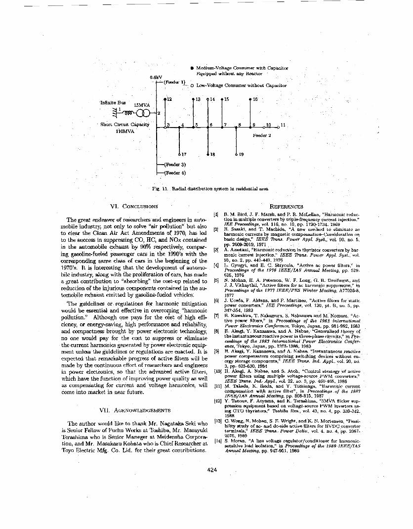
Fig.11 shows a radial distribution system in a residen- tial area. The rated bus voltage is 6.6kV(lineto-line), and the rated frequency is 50Hz. The equivalent inductive re- actanceupstream of bus 2, including the leakage reactance of a primary distribution transformer of 15MVA, is to be estimated from the short circuit capacity of 1lOMVA. The transformer supplies four distribution feeders consisting of feeders 1-4. For the sake of simplicity, only feeder 2 is con- sidered under the mumption that feeders 1, 3 and 4 are disconnected from the transformer. Overhead distribution lines, which are classified into a primary line and branch lines in feeder 2, are assumed to be LR circuits because it is reasonable to neglect the effect of stray capacitors of the distribution lines on the 5th and 7th harmonic voltage and current. Feeder 2 services electric power to eleven medium- voltage consumers of 200-24OkW, which install shunt ca- pacitors without any reactor, and to six low-voltage con- sumers of 50-130kW, which have no shunt capacitor. The total capacity of the loads is 2.99MW, and that of the shunt capacitors for power factor improvement is 0.99Mvar. Har- monic propagation occurs in feeder 2.around the 7t P har- monic frequency (350Hz); the 7th harmonic voltage is am- plified by four times at the rated load of 2.99MW and by eight times at no load. This results from series and/or par- allel resonance between inductive reactances of the distri- bution lines, along with the equivalent inductive reactance upstream of bus 2, and capacitive reactances of the shunt capacitors on feeder 2.
Each of the following items is the moat basic concept of the control strategy and site selection of a shunt active filter which is intended to be installed on the primary line of feeder 2 in Fig.11.
Voltage detection in the timedomain is stable irrespec- tive of installation point.
0 The shunt active filter adopting the voltage detection, which is installed in the vicinity of a harmonic-pre ducing load, is effective in the mitigation of voltage harmonics at the point of installation. The shunt active filter adopting the voltage detec- tion, which aims at damping harmonic propagation throughout feeder 2, should be installed at the end of the primary line of feeder 2, that is, bus 9. Har- monic mitigation is a welcome “by-product” of the shunt active filter, which comes from damping of har- monic propagation 1401.
423
b Medium-Voltage Conrnimer with Cawxitor m u i p p d without any a t o r
6.6kV (Feeder 1) - 0 Law-Voltage Consumer without Capacitor
nfinite Bus 15MVA I r2 -2 ‘ - 4 1: i:‘ 1: -8 1: -10 0 1 1
I 1
Feeder 2
Short Circuit Capacity 1 lOMVA
Feeder 4)
Fig. 11. Radial ddribution
VI. CONCLUSIONS
The great endeavor of researchers and engineers in auk+ mobile industry, not only to solve “air pollution” but also to c l w the Clean Air Act Amendments of 1970, has led to the success in suppressing CO, HC, and NOx contained in the automobile exhaust by 90% respectively, compar- ing gasdinefueled passenger cars in the 1990’s with the corresponding same class of cars in the beginning of the lWO’s. It is interesting that the development of automo- bile industry, along with the proliferation of cars, has made a great contribution to “absorbing” the cosbup related to reduction of the injurious cemponents contained in the au- tomobile exhaust emitted by gasolin&fueled vehicles.
The guidelines or regulations for harmonic mitigation would be essential and effective in overcolring “harmonic pollution.” Although one pays fox the cost of high effi- ciency, or energy-saving, high perforrnance and reliability] and compactness brought by power electronic technology, no one would pay for the cast to suppress or eliminate the current harmonics generated by power electronic equip ment unless the guidelines or regulations are enacted. It is expected that remarkable progrw ef active filters will be a i d e by the continuous effort of researchers and engineers in power eiectronics, so that the advanbed active filters, which have the function of improving power quality as well as compensating for current and ’voltage harmonics] will come into market in near future.
VI I. ACKNOWLEDGEMENTS
system in residential area
REFERENCES (11 B. M. Bird, J. F. Marsh, and P. R. Mcbllan, “Harmonic reduc-
tion in multiple converters by trfpbfreqiaency current injection,” IEE ProceedmgJ, vol. 116, no. 10, pp. 1730-1734, 1969 H. Sasaki, and T. Machida, “A new meiLod to eliminate ac harmonic currents by magnetic Cnmpensation-Conside~t~on on basic design,” IEEE %na. Appl. Sysk, vol. 90, no. 5, pp. 20042019, 1971
(31 A. Ametani, “Harmonic redu thyristor converters by har- monk current injection,” IEEE %M. Power Appl. Syst , vol. 95, no. 2, pp. 441-449, 1976 L. Gyugyi, and E. C. Strycula, “Active ac power filters,” in P r o d i n g s of the 1976 IEEE/IAS Annual Meeting, pp 529- 535, 1976 N. Mohan, H. A. Peterson, W. F. Long, G. R. Dreifuerst, and J. J. Vithaythil, “Active filters for ac harmonic suppression,” in Proceedings of the 1977 IEEE/PES Wznter Meeting, A77026-8, 1977 J. Uceda, F. Aldana, and P. Martinez, “Active filters for static power converters,” IEE Proceedings, vol. 130, pt. B, no. 5, pp. 347-354, 1983 H. Kawahira, T. Nakamura, S. Nskazawa and M. Nomum, “Ac- tive power filters,” in Procetdmgs of the 1983 Internatimal Power Electmniw Conference, Tokyo, Japan, pp. 981-992, 1983 H. Akagi, Y. Kanazawa, and A Nabae, “Generalized theory of the instantaneous reactive power in three-phase circuits,” in Fro- ceedings of the 1983 International Power Electmniw Confer- ence, Tokyo, Japan, pp. 1375-1386, 1983 H. Akagi, Y. Kanazawa, and A. Nabae, “Instantaneous reactive power compensators comprising switching devices without en- e r a storage components,” IEEE ”a. Ind. Appl., vol. 20, no. 3, pp. 625-630, 1984
(101 H. Akagi, A. Nabae, and S . Atoh, “Control strategy of active power filters using multiple voltag+source PWM converters,” IEEE %na. Ind. Appl., vol. 22, no. 3, pp. 460-465, 1986
Ill] M. Takeda, K. Ikeda, and Y. Tominaga, “Harmonic current compensation with active filtsr”, in Proceadings of the 1987 IEEE/IAS Annual Meebng, pp. 808815, 1987
(121 Y. ”.moue, F. Aoyama, and K. Terashima, “5MVA flicker sup- pression equipment based on voltage-source PWM inverters us- ing GTO thyristors,” Toshiba Rev., vol. 43, no. 4, pp. 339-342, 1988
121
[4]
15;
(61
(71
[8]
191
The author would like to thank Mr. Nagat& Seki who [I31 c* WO%, N. Mohan, s E. Wright, and K. N. Mortensen, “Fe&- bility study of ac- and dc-side active filters for HVDC converter terminals,” IEEE m ~ . power Deliv., VOI. 4, no. 4, pp. 21x7- 20751 *989
(141 S . Moran, “A line voltage regulator/conditioner for harmonic- asnsitive load isolation,” in Pmceedings of the 1989 IEEE/IAS Annual Meeting, pp. 947-951, 1989
is Senior Fellow of Fuchu Works at Toshiba, Mr. Masayuki Terashima who is Senior Maneger at Meidensha Corpor& tion, and Mr. at Toyo Electric Mfg. Co. Lid. for their great contribkions.
Kohata who is chief
424
(151 H. Akagi, Y. Tsukamoto, and A. Nabae, “Analysis and design of an active power filter using quad-series voltagesource PWM converters,” IEEE Zhns Ind Appl., vol 26, no. 1, pp. 93-98, 1990
[E] F. Z. Peng, H. Akagi, and A. Nabae, “A study of active power filters using quad-series voltage-source PWM converters for har- monic compensation,” IEEE ’Runs. Power Electronics, vol. 5 , no. 1, pp. 9-15, 1990
1171 W. M. Grady, M. J. Samotyj, and A. H. Noyola, “Survey of active power line conditioning methodologies,” IEEE %m. Power Deliv., vol. 5, no. 3, pp 15361542, 1990
1181 F. 2. Peng, H. Akagi, and A. Nabae, “A new approach to har- monic compensation in power systems-A combined system of shunt passive and series active filters,” IEEE %ns. Ind. Appl., vol. 26, no. 6, pp. 983-990, 1990
(191 E. H. Watanabe, “Series active filter for the dc side of HVDC transmission systems,” in Proceedrngs of the 1990 International Power Electronics Conference, Tokyo, Japan, pp. 1024-1030, 1990
1201 H. Fujita, and H Akagi, “A practical approach to harmonic compensation in power systems-Series connection of passive and active filters,” IEEE ”8. Ind. Appl., vol. 27, no. 6, pp. 1020- 1025, 1991
1211 W. M. Grady, M. J. Samotyj, and A. H. Noyola, “The applica- tion of network objective functions for actively minimizing the impact of voltage harmonics in power systems,” IEEE %ns. Power Deliu., vol. 7 , no. 3, pp. 13741386, 1992
(221 L. Gyupyf, “A unified power flow control concept for flexible ac transmission systems,” IEE Proceedings, vol. 139, pt. C, no. 4, pp. 323331, 1992
1231 F. Z. Peng, M. Kohata, and H. Akagi, “Compensation charac- teristics of shunt and series active filters.” in Proceedings of the 1992 Chanese-Japaneae Power Electronics Conference, Beijin, China, pp. 381-387, 1992
(241 F. Z. Peng, H. Akagi, and A. Nabae, “Compensation character- istics of the combined system of shunt passive and series active filters,” IEEE %ns. Ind. Appl., vol. 29, no. 1, pp. 144-152, 1993
1251 W. Zhang, G. Asplund, A. Aberg, U. Jousson, and 0. E f . “Active dc filter for HVDC system-A test installation in the Konti-Skan at Lindome converter station,” IEEE f i n s . Power Deliv., vol. 8, no. 3, pp. 15941605, 1993
[26] H. Akagi, “Trends in active power line conditioners,” IEEE rrCln.9. Rower Electrontcs, vol. 9, no. 3, pp. 263-268, 1994
[27] T-N. I&, M. Pereira, K. Rem, and G. Vaupel, “Active damping of resonances iu power systems,” IEEE Itnrw. Power Deliv., vol. 9, no. 2, pp. 1001-1008, 1994
[28] N. Tokuda, Y. Ogihara, M. Oshima, and T. Miyata, “AC- tive filter with series L-C circuit,” in Proceedings of the I994 IEEE/PES International Conferace on Hannonics in Power System, pp. 242-249, 1994
[29] N. Balbo, R. Penzo, D. Sella, L. Malesani, P. Mattavelli, and A. Zuccato, “Simplified hybrid active filters for harmonic compen- sation in low voltage industrial applications,” iu Proceedings of the 1994 IEEE/PES International Conference on Hannoniw in Power Systems, pp. 263-269, 1994
1301 J. 0. Krah, and J. Holtz, “Total compensation of line-side switching harmonics in converter-fed ac locomotives,” in Pro- ceedings of the 1994 IEEE/IAS Annual Meeting, pp. 913-920, 1994
B
International Power Electronics Conference, Yokohama, Japan,
[36] A. van Zyl, J. H. R. Enslin, W. H. Steyn, and R. SpBe, “A new unified approach t o power quality management,” in Proceedings of the 1995 IEEE/PELS Power Electronics Specialist Confer- ace, pp. 183-188, 1995
[37j S. Bhattacharya, and D. Divan, “Design and implementation of a hybrid series active filter system,” in Proceedings of the 1995 IEEE/PELS Power Electronics Specialist Conference, pp. 189- 195, 1995
1381 F. Kamran, and T. G. Habetler, “Combined deadbeat control of a seriercparallel converter combination used as a universal power filter,” in Proceedings of the 1995 IEEE/PELS Power Electronics Specialiat Conference, pp. 196-201, 1995
[39] H. Akagi, and H. Fujita, “A new power line conditioner for har- monic compensation in power systems,” IEEE Zhns. Powev De- b., vol. 10, no. 3, pp. 1570-1575, 1995
[40] H. Akagi, “Control strategy and site selection of a shunt active filter for damping of harmonic propagation in power distribu- tion systems,” t o be presented at the 1996 IEEE/PES Wznter Meeting, Jan. 21-25, 1996
pp. 1639-1644, 1995
Hirofumi Akagi(M’87, SM’94) was born in Okayama-city, Japan, on August 19, 1951. He received the B.S degrcs from Nagoya Institute of Technology in 1974 and the M.S. and Ph.D. degrees from Tokyo Institute of Technology in 1976 and 1979, respectively, all in electrical en- gineering. In 1979, he joined Nagaoka Univer- sity of Technology as assistant and then asso- ciate Professor in the deDartment of electrical
-
engineering. In 1987, he was visiting scientist at the Massachusetts Institute of Technology
for ten months. Since 1991, he has been professor in the department of electrical
engineering at Okayama University. His research interests are utility applications of power electronics such as active filters and FACTS equipment, ac motor drives, and high frequency inverters and their applications. He has received five IEEE/IAS Society and Committee Prize Paper Awards including the First Prize Paper Award in the IEEE Transactions on Industry Applications for 1991.
1311 E. Ooba, “Present states of voltage distortion and harmonic interference in power systems.” OHM, pp. 31-36, 1994 (in Japanses)
[32] J. HSfner, M. Aredes, and K Heumann, “A combined system of a passive filter and a shunt active power filter to reduce line current harmonics,“ in Proceedings of the 1995 Internatronal Power Electronics Conference, Yokohama, Japan, pp. 388-393, 1995
1331 M. Takeda, S. Murakami, et al., “Development of an SVG series for voltage control Over three-phase unbalance caused by railway load,” in h c e a f i n g s of the 1995 International Power Electron- ics Conference, Yokohama, Japan, pp. 603-608, 1995
Kishida, et al., “Self-Commutated Static Var Gen- eratorti at g i n t a h t s u k i Substation,” in Proceedmngs of the 1995 Intefnatimal Pow@ Electronics Conference. Yokohama, Japan, pp. 609-614, 1995
1351 W. Ofosu-Amah, S. Tanaka, K. Miura, and S. Tadakuma, “A dc active filter for traction systems,” in Proceedings of the 1995
1341 A. Iiuka,
425