Embed Size (px)
Citation preview

CC-936A
Rotary clamp cylinder double acting spatter adherence prevention typeNew Products
RCC2-G4 Series
Features
A fiber aggregate (lube keeping structure) impregnated with spatter adherence prevention agent is used to prevent spatter from sticking and solidifying onto the piston rod during arc welding.
A metal scraper (coil scraper) helps remove spatter adhering to the piston rod.
The spatter adherence prevention agent is supplied steadily for a long time, improving durability over general cylinders used in spatter environments.
Refer to safety precautions on “Pneumatic Cylinders I” catalog (No. CB-029SA).
New product
Long life even in environments containing spatter
Overview
Spatter adherence prevention has been incorporated in the RCC2 Series configured of the square space-saving cylinder with the built-in rotary clamp mechanism.
Spatter adherence prevention agent supply/absorptionA cap i l l a ry tube e f fec t app l ies the spa t te r adherence prevention agent evenly and regularly to the sliding surface and also absorbs any excess.
Dust wiper functionFine spatter is collected into the fiber aggregate to reduce contamination on the sliding section and prevent entry into the cylinder body.
Coil scraper
Lube keeping structure
Features of lube keeping structure Lube keeping structure cross section (× 180)
�
RCC2-G4 Series
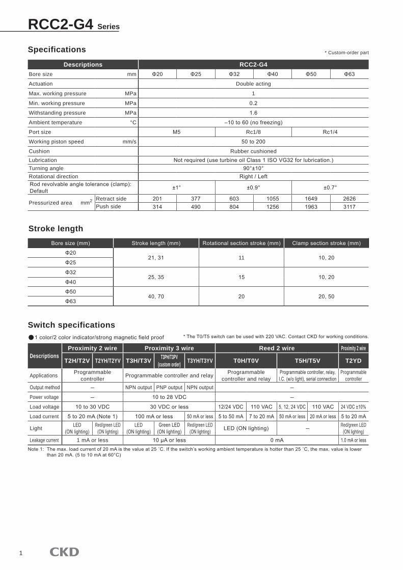
Specifications
Descriptions RCC2-G4Bore size mm Φ20 Φ25 Φ32 Φ40 Φ50 Φ63
Actuation Double acting
Max. working pressure MPa �
Min. working pressure MPa 0.2
Withstanding pressure MPa 1.6
Ambient temperature °C –10 to 60 (no freezing)
Port size M5 Rc�/8 Rc1/4
Working piston speed mm/s 50 to 200
Cushion Rubber cushionedLubrication Not required (use turbine oil Class 1 ISO VG32 for lubrication.)Turning angle 90°±10°Rotational direction Right / LeftRod revolvable angle tolerance (clamp): Default ±1° ±0.9° ±0.7°
Pressurized area mm2 Retract side 201 377 603 1055 1649 2626Push side 314 490 804 1256 1963 3117
Bore size (mm) Stroke length (mm) Rotational section stroke (mm) Clamp section stroke (mm)
Φ2021, 31 �� 10, 20
Φ25
Φ3225, 35 15 10, 20
Φ40
Φ5040, 70 20 20, 50
Φ63
Switch specifications
DescriptionsProximity 2 wire Proximity 3 wire Reed 2 wire Proximity 2 wire
T2H/T2V T2YH/T2YV T3H/T3V T3PH/T3PV (custom order) T3YH/T3YV T0H/T0V T5H/T5V T2YD
Applications Programmable controller Programmable controller and relay Programmable
controller and relayProgrammable controller, relay, I.C. (w/o light), serial connection
Programmable controller
Output method ― NPN output PNP output NPN output ―
Power voltage ― 10 to 28 VDC ―
Load voltage 10 to 30 VDC 30 VDC or less 12/24 VDC 110 VAC 5, 12, 24 VDC 110 VAC 24 VDC ±10%
Load current 5 to 20 mA (Note 1) 100 mA or less 50 mA or less 5 to 50 mA 7 to 20 mA 50 mA or less 20 mA or less 5 to 20 mA
Light LED (ON lighting)
Red/green LED (ON lighting)
LED (ON lighting)
Green LED (ON lighting)
Red/green LED (ON lighting) LED (ON lighting) ― Red/green LED
(ON lighting)Leakage current � mA or less 10 μA or less 0 mA 1.0 mA or less
1 color/2 color indicator/strong magnetic field proof
Stroke length
Note 1: The max. load current of 20 mA is the value at 25 ˚C. If the switch’s working ambient temperature is hotter than 25 ˚C, the max. value is lower than 20 mA. (5 to 10 mA at 60°C)
* The T0/T5 switch can be used with 220 VAC. Contact CKD for working conditions.
* Custom-order part
2
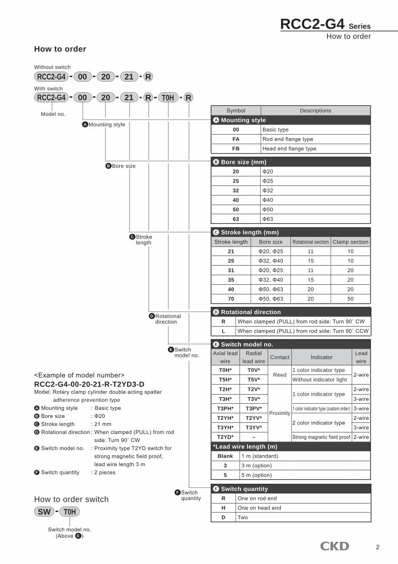
How to orderRCC2-G4 Series
How to order
Symbol Descriptions
A Mounting style00 Basic type
FA Rod end flange type
FB Head end flange type
B Bore size (mm)20 Φ20
25 Φ25
32 Φ32
40 Φ40
50 Φ50
63 Φ63
E Switch model no.
B Bore size
Model no.
C Stroke length (mm)Stroke length Bore size Rotational section Clamp section
21 Φ20, Φ25 �� 10
25 Φ32, Φ40 15 10
31 Φ20, Φ25 �� 20
35 Φ32, Φ40 15 20
40 Φ50, Φ63 20 20
70 Φ50, Φ63 20 50
00 20 21RCC2-G4 R RT0H
00 20 21RCC2-G4 R
F Switch quantity
<Example of model number>RCC2-G4-00-20-21-R-T2YD3-DModel: Rotary clamp cylinder double acting spatter
adherence prevention typeA Mounting style : Basic typeB Bore size : Φ20C Stroke length : 21 mmD Rotational direction : When clamped (PULL) from rod
side: Turn 90˚ CWE Switch model no. : Proximity type T2YD switch for
strong magnetic field proof, lead wire length 3 mF Switch quantity : 2 pieces
How to order switch
Without switch
With switch
SW T0H
F Switch quantityR One on rod end
H One on head end
D Two
Switch model no.(Above E )
A Mounting style
D Rotational directionR When clamped (PULL) from rod side: Turn 90˚ CW
L When clamped (PULL) from rod side: Turn 90˚ CCW
D Rotational direction
C Stroke length
E Switch model no.Axial lead
wireRadial
lead wireContact Indicator
Lead wire
T0H* T0V*Reed
� color indicator type2-wire
T5H* T5V* Without indicator light
T2H* T2V*
Proximity
� color indicator type2-wire
T3H* T3V* 3-wire
T3PH* T3PV* 1 color indicator type (custom order) 3-wire
T2YH* T2YV*2 color indicator type
2-wire
T3YH* T3YV* 3-wire
T2YD* – Strong magnetic field proof 2-wire
*Lead wire length (m)Blank 1 m (standard)
3 3 m (option)
5 5 m (option)
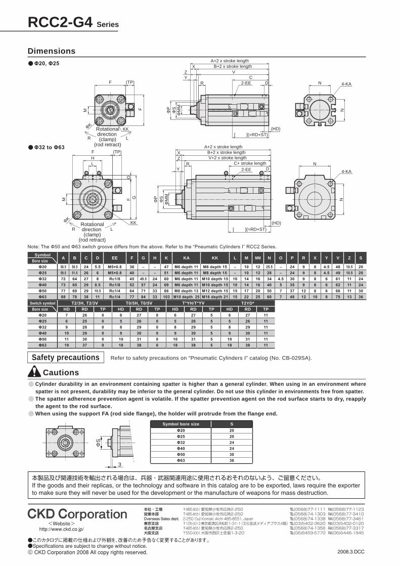
RCC2-G4 Series
Dimensions
CautionsCylinder durability in an environment containing spatter is higher than a general cylinder. When using in an environment where spatter is not present, durability may be inferior to the general cylinder. Do not use this cylinder in environments free from spatter.The spatter adherence prevention agent is volatile. If the spatter prevention agent on the rod surface starts to dry, reapply the agent to the rod surface.When using the support FA (rod side flange), the holder will protrude from the flange end.
Symbol bore size S
Φ20 20Φ25 20Φ32 24Φ40 24Φ50 30Φ63 36
Symbol A B C D EE F G H K KA KK L M MM N O P R X Y V Z S
Bore sizeΦ20 58.5 50.5 24 5.5 M5×0.8 36 – – 47 M6 depth 11 M8 depth 15 – 10 12 25.5 – 24 9 8 4.5 48 10.5 20Φ25 59.5 51.5 26 6 M5×0.8 40 – – 51 M6 depth 11 M8 depth 15 – 10 12 28 – 24 9 8 4.5 49 10.5 20Φ32 72 64 27 8 Rc1/8 45 49.5 24 60 M6 depth 11 M10 depth 15 10 14 16 34 4.5 30 9 8 6 61 11 24Φ40 73 65 29 8.5 Rc1/8 52 57 24 69 M6 depth 11 M10 depth 15 10 14 16 40 5 35 9 8 6 62 11 24Φ50 77 69 29 10.5 Rc1/4 64 71 33 86 M8 depth 13 M12 depth 15 15 17 20 50 7 37 12 8 6 66 11 30Φ63 88 78 38 11 Rc1/4 77 84 33 103 M10 depth 25 M16 depth 21 15 22 25 60 7 48 12 10 8 75 13 36
Switch symbol T2/3H, T2/3V T0/5H, T0/5V T*YH/T*YV T2YD*Bore size HD RD TP HD RD TP HD RD TP HD RD TP
Φ20 7 26 0 6 27 0 6 27 5 6 27 11Φ25 6 25 0 5 26 0 5 26 5 5 26 11Φ32 9 28 0 8 29 0 8 29 5 8 29 11Φ40 10 29 0 9 30 0 9 30 5 9 30 11Φ50 11 30 0 10 31 0 10 31 5 10 31 11Φ63 19 37 0 18 38 0 18 38 5 18 38 11
R L
KK
KK
F
M
M
(TP)
F (TP)
F
FO
G
N
[ ](=RD+ST)
L
ZX
Y
ZX
YR
D N 4-KA
N
N
4-KA
(HD)
[ ](=RD+ST)(HD)
2-EE
2-EE
C
DC+ stroke length
V+2 x stroke lengthB+2 x stroke length
A+2 x stroke length
VB+2 x stroke length
A+2 x stroke length
H
ab a b
R L
ΦP
ΦS
ΦM
M
ΦP
ΦK
ΦK
ΦS
ΦM
M
Rotationaldirection (clamp)
(rod retract)
Rotationaldirection (clamp)
(rod retract)
R
3
ΦS
Refer to safety precautions on “Pneumatic Cylinders I” catalog (No. CB-029SA).Safety precautions
Note: The Φ50 and Φ63 switch groove differs from the above. Refer to the “Pneumatic Cylinders I” RCC2 Series.
Φ32 to Φ63
Φ20, Φ25

![ML3 Series Offset Y [mm] - Steven Engineeringstevenengineering.com/pdf/32PHOTO_ML3_CONVERGENT.pdfPhotoelectric ML3 Series Ultraminiature Convergent Beam Mode (+) ( – ) NPN Output](https://img.dokumen.tips/doc/110x75/5ac5a9a47f8b9a57528dc46c/ml3-series-offset-y-mm-steven-engineer-ml3-series-ultraminiature-convergent.jpg)


![Compact Safety Beam Sensor [Type 4] ST4 SERIES · 2020. 7. 10. · Controller ST4-C11 Dual PNP transistor open-collector output × 1 system or Dual NPN transistor open-collector output](https://img.dokumen.tips/doc/110x75/60c3979285e5263407168379/compact-safety-beam-sensor-type-4-st4-series-2020-7-10-controller-st4-c11.jpg)