Embed Size (px)
Citation preview

New Innovative Anchor Solution for
Deepwater Mooring – Gravity Intalled
Anchors Reduce Time and Costs of
Marine Operations
Jon Tore Lieng – CTO Wokshop on Deepwater Subsea Tie-Back
Damai Puri Resort & Spa, Kuching, Sarawak, Malaysia
24th-26th January 2011

• Technology developer and provider of
innovative anchor solutions for floating
structures
• Expertise in marine soil mechanics
• Located in Trondheim, Norway

Available Anchor Types

DENNLA – Bruce
Anchors
STEVMANTA – Vryhof
Anchor Types drag embedment -
VLA

Suction
anchor
Anchor Types cont.
17
16
15
14
13
12
11
10
9
8
7
6
5
4
3
2
1
SEPLA
Suction
Embedded
Plate
Anchor
Pump
skid
D = 5-6.5m
L = 20-30m
Wdry = 120 – 250tons
20-30m
Soft
sediments
24
22
20
18
16
14
12
10
8
6
4
2

Seabed Installation of Suction Anchors
1
2 • Positioning
• Monitoring of
- verticality
- heading
- clearance
Pump
skid
Monitoring of
- verticality
- diff. pressure
- penetration
Evacuation of
entrapped water
Recovery of
pump skid
lifting wire
Total time at seabed:
3–9 hours depending on
anchor dimensions and
sediments.
3
-
-
-
-
-
-
-
-
-
-
-
-
-
-
-
-
-
-
-
-
-
-
-
-
-
-
-
-
-
-
-
-
-

Hydraulic
Pile hammer
D = 2-3m
L = 40-60m
Wdry= 100-200tons
Long Piles
Soft
sediments
56
52
48
44
40
36
32
28
24
20
16
12
8
4

Criteria for Needed Deep Water Anchor as defined by Deep-water Technology program – Norwegian Research Council 1995
Anchor installation must be simple and cost effective
The anchor must not be complicated or too expensive to
fabricate
Allow for taut leg mooring

Deep Penetrating Anchor – DPA™
Theoretical design
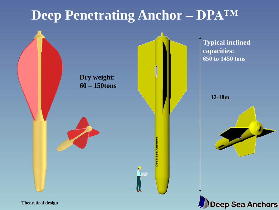
Deep Penetrating Anchor – DPA™
12-18m
Typical inclined
capacities:
650 to 1450 tons
Dry weight:
60 – 150tons
Theoretical design

A Real Torpedo
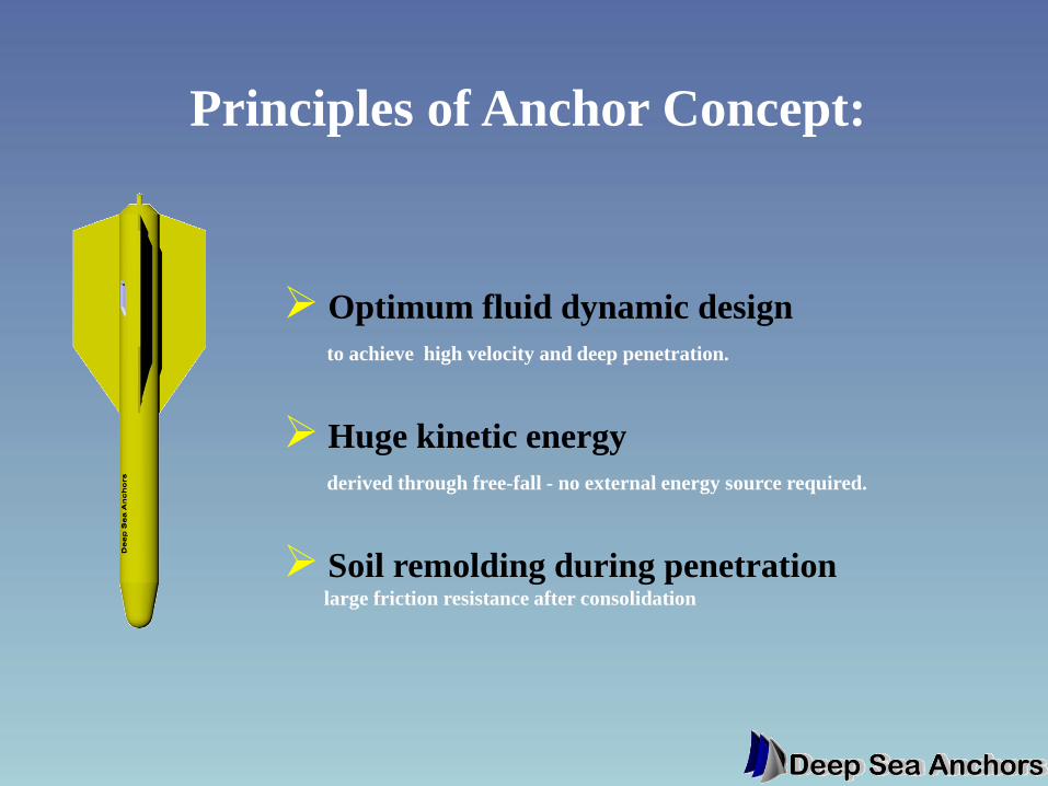
Optimum fluid dynamic design
to achieve high velocity and deep penetration.
Huge kinetic energy
derived through free-fall - no external energy source required.
Soil remolding during penetration
large friction resistance after consolidation
Principles of Anchor Concept:

Installation
may be installed
with one vessel

• Deep Penetrating Anchors for floating structures: – FPSOs/FPSs
– SPARs
– Riser Buoys
– MODUs
– Offshore Energy Power Units
• Geographical areas of use: – All areas where soft sea bed conditions are found
– No depth limitations

Keynote paper OTC (2004):
”Torpedo/DPA anchors appear to be the most
promising option for improvement in cost
reduction and simplifying installation.”
Technology Assessment of Deepwater Anchors Clarence J. Ehlers, et al.
Sr. Facilities Engineer ChevronTexaco/Exploration & Production Technology Co.
DPS/Floating Systems Unit/Anchors, Moorings & Risers Team

Suitable Geographical Areas

Technological Development
• Extensive theoretical research – CFD & geotechnical
• Economical evaluation – cost comparison with other solutions
• Small (1:25) lab and large (1:3) scale testing - Troll Field
• Full-scale pilot at the Gjøa Field leading to a qualified anchor in Q4 2009

Anchor velocity vs travelled distance
Anchor Velocity vs Drop Height - 75ton DPA
0
5
10
15
20
25
30
35
40
45
50
0 25 50 75 100 125 150 175 200 225 250
Drop height, (m):
An
ch
or
velo
cit
y, (m
/sec):
No drag resistance Viscos drag on anchor & chain
Assumed velocity 25m/sec at seabed
(70% of terminal velocity)
Drop height: minimum 50m
Terminal velocity: 37m/sec

Hydrodynamic Stability - monitored test
0
5
10
15
20
25
30
35
0.0 2.0 4.0
Dro
p d
ista
nc
e, (m
):
Anchor Tilt, (dgr):
sensor disturba
Final tilt ~ 1 dgr.

GJØA Full Scale Pilot
& Qualification

Installation of two
80t DPA™s at the
Gjøa Field in the
North Sea

Fabrication

Fabrication - Nose

DPA™s Ready for Transport to the
North Sea

Flukes 4m x 6m
steel plates
1.2m diam.
shank
Massive tip
13m
80t DPA™ as
installed at the
Gjøa Field
Characteristic
capacity
~ 800t

Gjøa Semi
NW
NE
SW
SE
Satellite F
Template E
Template D
Template C
Template B
All Templates
at 1850
orientation
NB! Not to scale.
Riser area
location
Gjøa field layout
N
Anchor
clusters
Typical Mooring Scheme

DPA Locations at Gjøa
Template E
Template
BCD
DPA 1
DPA 2
DPAs to be used for
both Template sites
DPAs
1.5kM
apart
Stiffer
soil
Softer
soil

±5o
Limited loading direction Omni-directional loading
Loading Direction

Installation Vessel –
Island Vanguard

Two DPA™s on Deck

DPAs on Deck of Island Vanguard

Container for instrumentation

Markings on Chain and Retrieval
Wire for Instrumentation

Anchor Drop
Configuration
Drop
height
50-75m
Loop
height
Installed anchor
Instrumentation
Permanent
mooring line
To stern roller Release
point
Trailing
chain
length
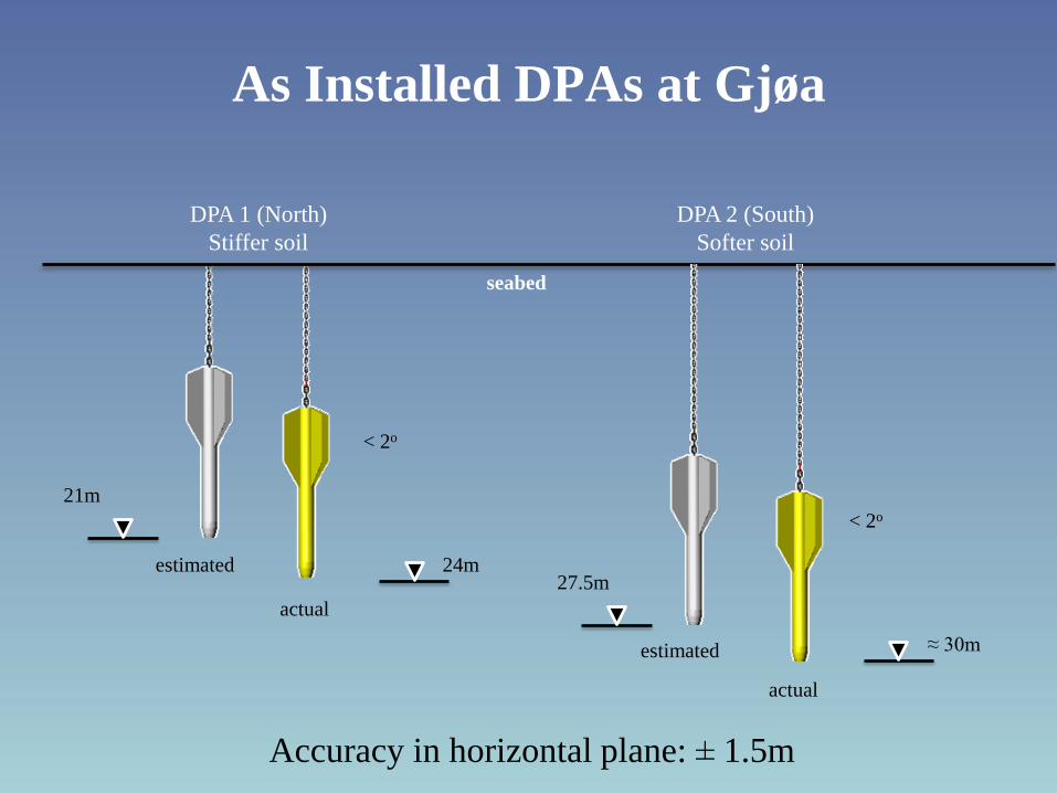
As Installed DPAs at Gjøa
estimated
actual
estimated
actual
seabed
DPA 1 (North)
Stiffer soil
DPA 2 (South)
Softer soil
< 2o
< 2o
24m
≈ 30m
21m
27.5m
Accuracy in horizontal plane: ± 1.5m

Qualified Technolgy
within Statoil

Available AHTS for Efficient Installation

Why DPA?
• Installation time and costs
• Standard Anchor Handling Vessel (AHTS)
• No external energy source required
• Precise horizontal positioning

Why DPA? Cont.
• Independent of water depth
• No proof loading required
• High utilization of deck storage area
• More cost effective