Embed Size (px)
Citation preview

1 FESAC-SP Whyte
New HTS superconductors + integrated high-B physics enable an innovative strategic vision for ���
US leadership in accelerated fusion energy development
G-2 Integrated steady-state & boundary in burning plasma
G-4 Control at high Qp
G-5 Predict & avoid damaging��� off-normal events
G-7 RF launchers & coupling
G-9 Tame PMI & heat exhaust
G-10-15 Integrated fusion materials & components
High-B physics: - High gain at small size - Margin to operational
limits & disruptions - Effective RF CD &
innovative launchers for steady-state
- High pressure boundary & PMI control
Demountable HTS coils & Modular replacement
G-8 High-B magnets Gaps HTS high Bpeak> 20 T
Superconductor coils
Steady-state Compact
FNSF/Pilot
Next 10 years HTS magnet R&D
HTS joints & Blanket R&D

2 FESAC-SP Whyte
A strategic plan should accelerate fusion development by considering critical knowledge gained in past decade
1. Large size à risks in cost and schedule���ITER successful fusion gain > 20 years away��� “At some point delay is equivalent to failure” ���FESAC 2007 Gaps report5 ���
2. Superconductors evolved (G-8) ���HTS1 tapes allow ~ double B field ���à Steady-state, high gain small devices ���
3. Boundary physics evolved (G-9) a) ELMs disallowed in ITER à ���
Transients disallowed in FNSF/Pilot/DEMO b) Power exhaust could threaten fusion viability���
& does not favor large size. c) Quiescent high-field SOL à locate RF launchers
Small + ���High-B +���Superconductor = ���Margin to disruptions + Steady-state + Reduced cost & schedule
Evolved���Strategy
Strategic Input
Key Observations

3 FESAC-SP Whyte
Size has risk: Lesson from fission & ITER���Minimize volume of first nuclear devices to assure
timely development of physics and technology
• JET ~ 100 m3 took < 5 years to construct
• FIRE B~10T burned at right size, but pulsed due to copper coils
Design'parameter'Shippingport2*“Pilot”*Fission*Plant*ca.*1954*
ITER3*“Pilot”*Fusion*Plant*ca.*2006*
Scale*factor*ITER/Shippingport!
Pthermal'(MW)' 236!! 500!! x*2.5!Core'volume'(m3)' 60!! ~1600!
(shield!+!TF)! x*27*
Cost'(2012'US'B$)' 0.6! ~!30! x*50*Cost'/'Core'volume'(M$/m3)' 10* ~*18* ~*2*Construction'time'to'“burn”'(years)' 3.3* ~*28*** x*8*!
VFIREVITER
~ 130
Cost &���schedule G-8 G10-15
4 FESAC-SP Whyte
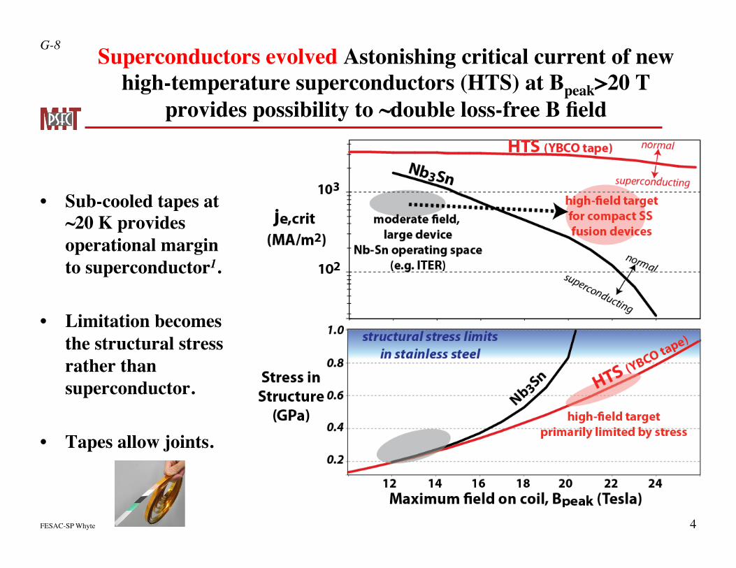
Superconductors evolved Astonishing critical current of new high-temperature superconductors (HTS) at Bpeak>20 T
provides possibility to ~double loss-free B field
• Sub-cooled tapes at���~20 K provides operational margin to superconductor1.
• Limitation becomes the structural stress rather than superconductor.
• Tapes allow joints.
G-8

5 FESAC-SP Whyte
Known physics scaling + Superconductor Bpeak > 20 T à High-gain burning plasma compact size & Steady state!
nT τ E
βNHq*2 R1.3B3
PfusionSwall
βN
22
q*2 RB4
ARC /w HTS superconductor
Gain Power density
FIRE12 ARC10,14
R (m) 2.14 3.2
Bo (T) 10 9.2
Qp >10 >10
Steady- state No Yes
Tritium breeding No Yes
Qelectric 0 ~ 4
FIRE /w ���copper coils
To scale
Cost &���schedule G-2 G-4
$∝ R3

6 FESAC-SP Whyte
B0~10 T, compact SC HTS tokamak enables more realistic ���high-Qp steady-state option by providing margin ���to intrinsic disruption, control & operation limits
Steady- state���
tokamak
B0���(T)
R (m)
Pelec (MW) Qp
Pn S
MW m2
ARIES-AT6���
SC-NbSn 5.8 5.2 +1000 44 3.3 2.5
ARC14���
SC-HTS 9.2 3.3 + 230 14 2.2 1.2
FNSF-AT4,7
Copper 5.5 2.7 - 600 2.6 1.6 1
Nuclear mission
Capital & Operating Costs / Economics
Cost & Schedule���G-2 G-4 G-5 G-8
Disruption damage���relative to ITER
Pn
Wth / SWth / S( )ITER
nT τ E
βNHq*2 R1.3B3
Operational limit diagram
Electrical cost13 ���~ 250-500 M$/FPY

7 FESAC-SP Whyte
Heat exhaust critical to the viability of all FNSF/Pilot designs ��� New edge physics favors small size + high gain à high B
Pheat ~ Pneutron1+ 5 /Qp( )
4~ R2
q// ~PheatBR
λq ~1Bp
ADX
Innovative solutions at
reactor-matched
B, q//
G-9
LaBombard
Evolved ���edge ���physics
q// ~ R B 1+ 5 /Qp( )
Neutron mission
US Leadership opportunity
Near-term Edge physics
FNSF design challenge
nT τ E
βNHq952 R1.3B3
Ref. 9

8 FESAC-SP Whyte
Efficient RF current drive is synergistic with high-B &���critical to developing robust steady-state in tokamaks
• Compels near-term research in high-field & inside launch RF.
Higher LHCD efficiency at high field
Quiescent PMI ���high-field-side RF ���
launchers
n=2x10²⁰
Control current profile ���at small R, T~12 keV ���for optimized AT13,14
ICD/I ~ 37% & Qp ~ 15
ARC
ARC η20 (A/W/m2)
G-2 G-7
R. Parker
US Leadership opportunity
ω ce
ω pe

9 FESAC-SP Whyte
FNSF mission favors demountable coils for modular replacement��� Finite resistance HTS joints à minimal Pcoil à Pilot option ���
US Leadership opportunity in configuration & maintainability
Copper FNSF-ST8���Pcoil~400 MW
Copper FNSF-AT7 ���Coil Pcoil~600 MW
ARC: Resistive joints /w HTS superconductors11���
Coil Pcoil~ 1 MW
Conceptual FNSF designs R/a=3.5 R/a=1.7 R/a=3
G-8 G-10 G-13 G-15

10 FESAC-SP Whyte
High-B physics: - High gain at small size - Margin to operational
limits & disruptions - Effective RF CD &
innovative launchers for steady-state
- High pressure boundary & PMI control
New HTS superconductors + integrated high-B physics enable an innovative strategic vision for ���
US leadership in accelerated fusion energy development
G-2 Integrated steady-state & boundary in burning plasma
G-4 Control at high Qp
G-5 Predict & avoid damaging��� off-normal events
G-7 RF launchers & coupling
G-9 Tame PMI & heat exhaust
G-10-15 Integrated fusion materials & components
Demountable HTS coils & Modular replacement
G-8 High-B magnets Gaps HTS high Bpeak> 20 T
Superconductor coils
Steady-state Compact
FNSF/Pilot
Next 10 years HTS magnet R&D
HTS joints & Blanket R&D
Minervini: HTS magnets
LaBombard PMI & heat exhaust
Parker RF current drive
ADX

11 FESAC-SP Whyte
Backup materials

12 FESAC-SP Whyte
References 1. "Engineering critical current vs. applied magnetic field," P.J. LEE Florida State University, National High Magnetic Field Laboratory ���
http://fs.magnet.fsu.edu/~lee/plot/plot.htm 2. "Shippingport Atomic Power Station" Historic American Engineering Record, Dep. Interior, Philadelphia PA 19106 Report HAER No. PA-81 3. "ITER funding profile" http://fire.pppl.gov/#NewsSection, September 2012 US cost estimate of 3.1 B$ as 9% partner. ���
ITER cost ~ 3.1 B$ / 9% ~ 30 B$ 4. V. Chan, et al. "A fusion development facility on the critical path to fusion energy," Nucl. Fusion 51 083019 (2011). 5. "Priorities, Gaps and Opportunities: Towards a long-range strategic plan for magnetic fusion energy," FESAC report, M. Greenwald chair, Oct. 2007 6. F. Najmabadi, et al. "The ARIES-AT advanced tokamak, Advanced technology fusion power plant," Fus. Eng. Des. 80 3 (2006). 7. A.M. Garofalo, et al. "A fast-track path to DEMO enabled by ITER and FNSF-AT," IAEA Fusion Energy Conference, FTP/P7-35 San Diego, CA
(2012) (Note: FNSF-AT version shown is with ECCD only) 8. J. Menard, et al. "Studies of ST-FNSF mission and performance dependence on device size," 1st IAEA DEMO Programme Workshop, UCLA, Los
Angeles CA Oct. 2012 9. T. Eich et al Nucl. Fusion 53 09031 (2013) 10. B. Sorbom, et al. " ARC: A compact, high-field disassemblable fusion nuclear science facility and demonstration power plant," being submitted to
Fusion Engineering & Design (2014). 11. Z. S. Hartwig, et al., "An initial study of demountable high-temperature superconducting toroidal field magnets for the Vulcan tokamak conceptual
design," Fusion Eng Design 87 (3), 201-214, 2012. 12. D. Meade, " Fusion, FIRE and and the Future," NRL seminar, December 2002 http://fire.pppl.gov/nrl_fire_120202.pdf 13. Electricity rate range: 50-100 $/MW-hr x 8760 hr / Full-power Year x 600 MW = 262-525 M$/FPY 14. D. Whyte, “Smaller & Sooner: Exploiting new superconductors for compact robustly steady-state tokamak reactor designs.” JET/CCFE seminar,
April 2014 http://fesac_2014.psfc.mit.edu/index.php/Main_Page#High-Field_Approach

13 FESAC-SP Whyte
Foundations Year 1-3 Year 4-7 Year 8-10 FNSF options
Transport H98 OK, no X-point MARFE Disruptivity vs. performance���assessment Stability ELM-free
stationary ped.
Wave-particle Design HFS launch: LHCD & ICRF
Install, assess PMI & coupling
High ηCD, j profile control
Valid RF model & launchers
PMI Design divertors PMI diagnostics
Install divertors, q// vs. B physics
Integrated q// PMI solution @
high pressure
Heat exhaust/PMI solutions Solid vs liquid
Long Pulse
Plasma sustainment CD efficiency f(B) on HFS
Disruption rates away from limits
Current control toolkit
B-field sustainment Prototype HTS conductor & joints
Wound coils /w joints, HEP
B>20 T jointed coil demo
Cu vs. HTS Pilot?
Materials Erosion resistance high-Z PFC
Study: modular replacement
High-T, high-Z, low Eion divertor
Modular replacement
National ADX and HTS magnet and ADX initiatives are aligned and timely to the OFES ���
Burning Plasma Science mission
~17 M$/y ~4 M$/y + demo coil

14 FESAC-SP Whyte
ADX provides a critically needed ���near-term, small-scale step into the ITER/FNSF ���
heat exhaust & PMI parameter range
q// ~ PheatB / Rqθ ~ PheatBθ / R
pthermal (MPa)
// physics Projected heat flux
Atomic &���PMI
physics

15 FESAC-SP Whyte
Heat exhaust critical to the viability of all FNSF/Pilot designs ��� New edge physics favors small size + high gain à high field
Pheat ~ Pneutron1+ 5 /Qp( )
4~ R2
q// ~PheatBR
λq ~1Bp
ADX
Innovative solutions at
reactor-matched
B, q//
G-9
LaBombard
Evolved ���edge ���physics
q// ~ R B 1+ 5 /Qp( )
Neutron mission
US Leadership opportunity
Near-term Edge physics
FNSF design challenge
nT τ E
βNHq952 R1.3B3
Ref. 9
q// ~1+ 5 /Qp( )B1.3

16 FESAC-SP Whyte
ARC: 9 Tesla “JET”, 250 MW net electricity���Steady-state tokamak far from disruptive limits
Nuclear Fusion Power 525 MW
Blanket & Depth Liquid FLiBe > 0.8 m ηthermal / Tblanket ~ 0.5 / ~ 900 K
Tritium breeding ratio 1.11 Plasma core
R / a / 𝜅 3.3 m / 1.1 m / 1.8 B0 9.2 T
q95 / qmin 7.2 / ~ 3 𝛽N / H89 2.59 / 2.7
G89 : 𝛽N H98 / q952 ~ 0.15
Greenwald fraction ~0.6 RF current sustainment
CD Efficiency > 0.4 1020 A/W/m2 Bootstrap fraction 63%
Margin to limits! Scenario already achieved In present tokamaks

17 FESAC-SP Whyte
ARC exploits two features of new SC:��� Bcoil,max~23 T + Tapes used for joints
1. Support ring, 2. Top TF leg ���4. Mechanical joint 6. Epoxy enforcement 7. Electrical joint
Peak stress ~ 0.75 GPa ~30% margin for 316SS LN

18 FESAC-SP Whyte
ARC exploits two features of new SC:��� Bcoil,max~23 T + Tapes used for joints
1. Support ring, 2. Top TF leg ���4. Mechanical joint 6. Epoxy enforcement 7. Electrical joint
“Comb-style” TF resistive joints are expected to lead ���to ~ 1 MWelectric dissipation
19 FESAC-SP Whyte
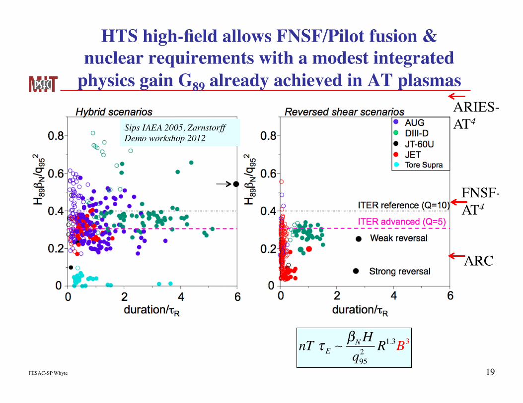
HTS high-field allows FNSF/Pilot fusion & nuclear requirements with a modest integrated
physics gain G89 already achieved in AT plasmas
Sips IAEA 2005, Zarnstorff Demo workshop 2012
FNSF-���AT4
ARIES- AT4
ARC
nT τ E
βNHq952 R1.3B3

20 FESAC-SP Whyte
B~10 T, SC compact tokamak provides realistic ���high-gain steady-state option far from ���
intrinsic operating and disruptive limits Nuclear & Electricity
Power���exhaust
Steady-state &��� Disruptions
Capital & Operating Costs
Violation or within 10% ���of intrinsic limits:���
fbs=1, 𝜅 < 5.4/A, no-wall βN, ���kink q*~2, density limit fGr =1
Qp < 5 à excess relative���heat loading per neutron
Electrical cost ���~ 500 M$/FPY
Cost & Schedule���G-2 G-4 G-5 G-8
Steady- state���
tokamak
B���(T)
R (m)
Pelec (MW)
Pf (MW)
Pn / S ���(MWm-2) Qp
Pheat / 4Pn
fBS 𝜅 βN q* fGr
ARC ���SC-HTS 9.2 3.3 230 525 2.2 14 1.3 0.63 1.8 2.6 4.8 0.65
ARIES-AT���
SC-NbSn 5.8 5.2 1000 1760 3.3 44 1.1 0.92 2.2 5.4 2.1 0.95
FNSF-AT
Copper 5.5 2.7 -600 230 1.6 2.6 2.9 0.74 2.3 3.7 2.8 0.63

21 FESAC-SP Whyte
ACCOME has optimized large advantages of HFS-LHCD + poloidal launch location near X-point
n// accessible

22 FESAC-SP Whyte
Optimized CD efficiency leads to substantial control of AT current profile below no-wall βN limit

23 FESAC-SP Whyte
HFS-LHCD+ high B: Excellent penetration at Lawson criterion minimum <T>~12 keV, ���
~ doubled CD efficiency to standard scenarios
pth~ 0.8 MPa
0.4
0.6
0.8
1.0
0.2
0.4
0.6
0.8
1.0
10 15 20Maximum B on coil, Bcoil, max (T)
10 15 20 10 15 20 10 15 20
0.2
r/a
!
20 a
t min
. r/a
(a) "=0.33 〈T〉=12 keV
HFS launch
LFS launch
(b) "=0.33 〈T〉=18 keV (c) "=0.25 〈T〉=12 keV (d) "=0.45 〈T〉=12 keV
LHCD windows: LFS launch
HFS launch
B0 (T) 5 10 5 10 5 10 5 2.5

24 FESAC-SP Whyte
Small scale + demounting has surprising synergistic benefits:���
Reduced volume à ���reduce cool/heat time to ~2-3 days ���
of structure��� à Modular maintenance
A single, module is only replaced unit ���(vacuum vessel + PFCs + Built-in test stations integrated off-site)

25 FESAC-SP Whyte
Small scale à Modular VV à ���Low-risk immersion liquid blanket ���
(FLiBe) for FNSF
FLiBe
Tritium Breeding Ratio: 1.14������Eliminate blanket solid waste No “blanket” DPA limit

26 FESAC-SP Whyte
FLiBe provides outstanding heat removal capabilities at high T à thermal efficiency

27 FESAC-SP Whyte
Lessons from ARC.. • Is NOT that ARC is the ultimate, best fusion reactor design..
• Or that every detail of ARC is settled and easily done…
• ARC and it innovations was the result of ~dozen MIT students working for a semester+ , showing that it was feasible to produce high gain, SS reactor at JET size
• The real lesson of ARC is that when you change the most fundamental aspects of your MAGNETIC fusion device, i.e. scale, B strength and coil configuration, you also fundamentally change the design options and solutions open to you…