Embed Size (px)
Citation preview
BARC NEWSLETTERTechnology Development Article
March-April 2015 | 19
Abstract
The New Hot-Cells Facility (NHF) of Post Irradiation Examination Division (PIED) at RLG, BARC is designed for
the Post Irradiation Examination (PIE) of irradiated nuclear fuels and structural components from research and
power reactors. The NHF consists of two hot cells made of heavy density concrete and a number of lead cells.
The hot cells are designed to handle b-g radioactivity. The lead cells in the facility are equipped with testing
machines for evaluation of mechanical properties of irradiated materials. In addition, the facility will be also
used for failure analysis of nuclear reactor components. This article describes the salient features of the hot cells
and the PIE capabilities of the NHF.
New Hot Cell Facility for Post Irradiation ExaminationAnil Bhandekar, K.M. Pandit, M.P. Dhotre, P. Nagaraju*, B.N. Rath, Prerna Mishra,
Sunil Kumar, J.S. Dubey, G.K. Mallik, J.L. SinghPost Irradiation Examination Division
*Hot Lab Utilities & Egineering Services Section
Introduction
Reliable performance of nuclear fuels and critical
core components have a large bearing on the
economics of nuclear power and radiation safety
of the plant operating personnel. In view of
this, PIE is periodically carried out on fuels and
components to generate feedback information
which is used by the designers, fabricators and
the reactor operators to bring about suitable
changes for improved performance of the fuel and
components. Examination
of the fuel bundles has
to be carried out inside
hot cells due to the high
radioactivity associated
with them. In the last four
decades, post irradiation
examination of different
types of experimental as
well as power reactor
fuels and structural
components used in the
core of the reactor has
been carried out in the old
hot cells facility of the Post
Irradiation Examination
Division of BARC. The new
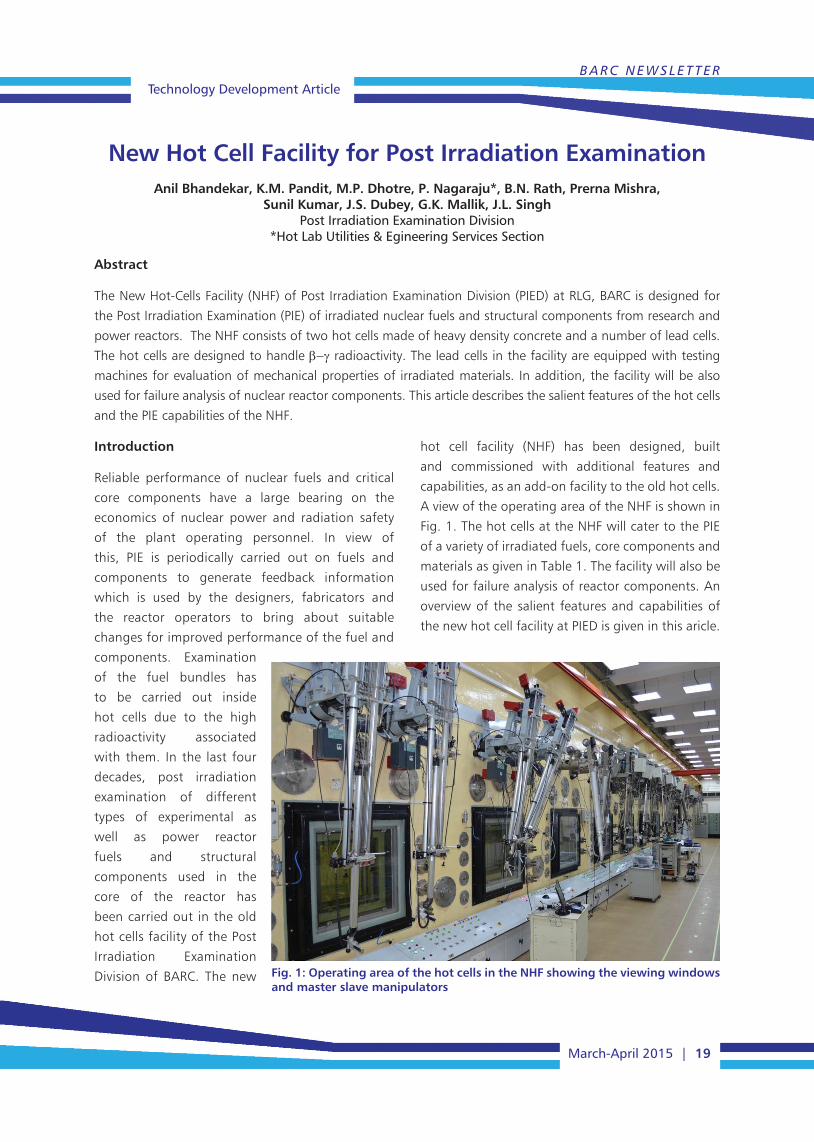
hot cell facility (NHF) has been designed, built
and commissioned with additional features and
capabilities, as an add-on facility to the old hot cells.
A view of the operating area of the NHF is shown in
Fig. 1. The hot cells at the NHF will cater to the PIE
of a variety of irradiated fuels, core components and
materials as given in Table 1. The facility will also be
used for failure analysis of reactor components. An
overview of the salient features and capabilities of
the new hot cell facility at PIED is given in this aricle.
Fig. 1: Operating area of the hot cells in the NHF showing the viewing windows and master slave manipulators

Technology Development ArticleBARC NEWSLETTER
20 | March-April 2015
New Hot Cell Facility (NHF)
The new hot cell facility has two areas for handling
radioactive materials. They are:
• Hotcellsforhandlinghighlyradioactiveirradiated
fuels and structural materials
a. NU fuel bundles and MOX fuel bundles from
the PHWRs
b. MOX fuel bundles and LEU bundles from the
BWRs
c. Experimental MOX fuels irradiated in research
reactors
d. MOX/LEU fuel bundles from future PWRs
e. Fuels of research reactors & future reactors
such as AHWR, CHTR, etc.
f. Pressure tubes, Calandria tubes and End
fittings of the PHWRs
g. Control blades of BWRs and Control elements
of the PHWRs
h. Shut off rods of the PHWRs
i. Other core internals which are to be assessed
j. Surveillance specimens from BWRs
k. Material irradiated for materials development
programme
Table 1: List of fuels and components which can be examined in NHF
• Leadcellsandlowactivelaboratoriesforhandling
of specimens with a lower radiation field.
Comparison of New and Old Hot Cells
Fuel transfer port size
The old hot cells were designed for the PIE of
fuel from CIRUS reactor. The cell has a 150 mm
cylindrical port for introducing irradiated fuel/
structural component into the hot cell. This poses
a limitation on the size of the fuel/component that
can be introduced into the old hot cell. The new
hot cells have a transfer port with the maximum
opening of 500 mm x 500 mm section which will
facilitate loading of larger components like LWR fuel
assembly, control blade assembly, etc. into the cells
for PIE. Fig. 2 shows the (a) cold side and (b) hot side
of the fuel transfer port in the new hot cell.
Cell dimensions
The length of the hot cell in the NHF is 16.9 m as
compared to 4.8 m in the old hot cell. This provides
the advantage of examining longer components
such as full length irradiated pressure tube, LWR fuel
rods, etc. In the old hot cells, application of certain
techniques such as seamless gamma scanning of
long fuel elements like those of Dhruva was difficult.
Fig. 2: (a) Cold side and (b) hot side of the transfer port in the new hot cell
(a) (b)
BARC NEWSLETTERTechnology Development Article
March-April 2015 | 21
The NHF provides the facility of continuous scanning
of longer fuel elements.
Shielding Capacity
The shielding capacity of the old hot cells is up to 105
Ci of Co60. The hot cells at the NHF are capable of
handling higher activities up to 2.5 x10⁵ Ci of Co60 or
2.6x 10⁶ Ci of fission products.
Features of the New Hot Cells
The NHF consists of two hot cells, namely Cell-1
& Cell-2 and is designed to handle b-g radiation.
The front, rear and side walls of the cells are 1.5
m thick and are made of heavy density concrete
(density=3.4 g/cc). The bigger cell (Cell–1) is 16.9
m long, 2.1 m wide and 4.7 m high and the smaller
cell (Cell–2) is 5 m long, 2.1 m wide and 4.7 m
high. All regions of Cell–1 and Cell–2 are provided
with lead glass viewing windows, master slave
manipulators (MSMs), ports for in-cell camera and
service plugs, which are essential for carrying out
PIE. Cell-1 is fitted with seven radiation shielding
windows and seven pairs of rugged duty master
slave manipulators. Cell-2 is fitted with two radiation
shielding windows and two pairs of rugged duty
master slave manipulators.
Cell–1 is provided with three personnel entry doors
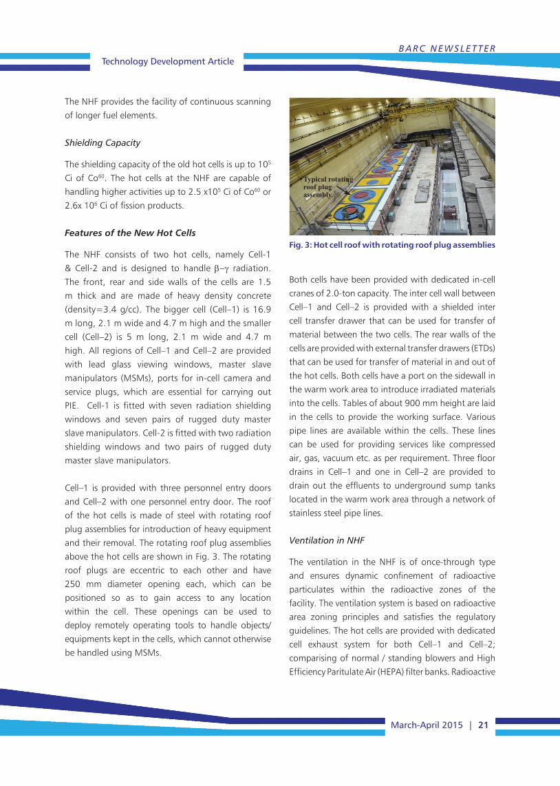
and Cell–2 with one personnel entry door. The roof
of the hot cells is made of steel with rotating roof
plug assemblies for introduction of heavy equipment
and their removal. The rotating roof plug assemblies
above the hot cells are shown in Fig. 3. The rotating
roof plugs are eccentric to each other and have
250 mm diameter opening each, which can be
positioned so as to gain access to any location
within the cell. These openings can be used to
deploy remotely operating tools to handle objects/
equipments kept in the cells, which cannot otherwise
be handled using MSMs.
Fig. 3: Hot cell roof with rotating roof plug assemblies
Typical rotating roof plug assembly
Both cells have been provided with dedicated in-cell
cranes of 2.0-ton capacity. The inter cell wall between
Cell–1 and Cell–2 is provided with a shielded inter
cell transfer drawer that can be used for transfer of
material between the two cells. The rear walls of the
cells are provided with external transfer drawers (ETDs)
that can be used for transfer of material in and out of
the hot cells. Both cells have a port on the sidewall in
the warm work area to introduce irradiated materials
into the cells. Tables of about 900 mm height are laid
in the cells to provide the working surface. Various
pipe lines are available within the cells. These lines
can be used for providing services like compressed
air, gas, vacuum etc. as per requirement. Three floor
drains in Cell–1 and one in Cell–2 are provided to
drain out the effluents to underground sump tanks
located in the warm work area through a network of
stainless steel pipe lines.
Ventilation in NHF
The ventilation in the NHF is of once-through type
and ensures dynamic confinement of radioactive
particulates within the radioactive zones of the
facility. The ventilation system is based on radioactive
area zoning principles and satisfies the regulatory
guidelines. The hot cells are provided with dedicated
cell exhaust system for both Cell–1 and Cell–2;
comparising of normal / standing blowers and High
Efficiency Paritulate Air (HEPA) filter banks. Radioactive

Technology Development ArticleBARC NEWSLETTER
22 | March-April 2015
areas are also provided with separate lab exhaust and
air supply system. Dust free cooled air is supplied in
all radioactive area except hot cells. The hot cell is
maintained at a negative pressure of 25 mm of water
column (WC) with respect to operating area. There are
20 air changes per hour in the hot cells. The elaborate
safety interlocks provided in the ventilation system
ensure radiological safety of the plant personnel and
public. Contaminated air passes through multiple
HEPA filter banks before being released through the
stack after monitoring, to ensure that the release
of radioactivity in the environment is within the
approved regulatory limits. The ventilation system
is provided with data acquisition and monitoring
system. Real time data of safety related parameters of
ventilation such as negative pressure in hot cells, air
changes per hour, pressure drop across HEPA filters
etc. is monitored and logged in the central console
located at operating area.
Areas associated with the Hot Cells
The facility is divided into four zones depending
on the probability of radioactive contamination.
The zones are coded white, green, amber and red,
with green having the lowest and the red having
the highest probability of contamination. The white
areas have a very remote chance of contamination by
radioactivity. Fig. 4 gives the plan of the NHF showing
the hot cells and associated areas.
The location of the operating area is shown in Fig. 4.
Remote operations of equipment kept inside the hot
cells are carried out from this area (see Fig. 1) using
MSM and viewing windows. Control consoles of the
in cell equipment and other measuring instruments
are at kept in this area.
The isolation area is on the rear of the hot cells and
acts as a buffer between the cells and the high bay
surrounding the cells. The isolation area is provided
with a 2T hand operated overhead travel underslung
crane. The cell exhaust filters are located in nine
separate pits below the isolation area floor.
The high bay surrounding the cells and isolation area
on three sides is called the warm work area and houses
a 40T/5T EOT crane. This area is used for receiving
shielded casks containing radioactive materials. An
airlock capable of accommodating a 30T trailer truck
Fig. 4: Plan of the NHF showing the hot cells and the associated areas depicting appropriate health physics colour coding

BARC NEWSLETTERTechnology Development Article
March-April 2015 | 23
is provided. Dollies running on rails are used to dock
the cask to the transfer port of the hot cell (Fig. 5).
Airlocks have also been provided for personnel entry
into the warm work area.
Dismantling of the Fuel Bundle
After preliminary survey of the fuel bundle for
its overall integrity, the fuel bundle is dismantled
to separate the fuel pins of the bundle for PIE
investigations. Mechanical cutting machine using
saw blade is installed in the hot-cells. Fig. 6 shows the
dismantling of a fuel bundle using the mechanical
cutting machine inside the hot cell as seen through
the cell window.
Fuel transport cask
Fuel transfer port
Fig. 5: Docking of the fuel transport cask with the fuel transfer port of the hot cell
Lead Cells and Low Active Laboratories
The low active laboratory is primarily used for carrying
out mechanical tests on irradiated test specimens.
Towards this an instrumented drop tower, servo
hydraulic & screw driven universal testing machines,
creep testing units and static load test setups have
been installed in the low active laboratory. The front
wall of the lead cells in this laboratory is made of
200 mm thick steel cased lead bricks and the rear
walls are made of 100 mm thick lead bricks. The
lead cells are fitted with articulated MSM, viewing
windows, hatches/door for personnel entry, transfer
ports and other handling facilities. The radioactivity
of the test specimens will be limited to a few mCi of
Co60 equivalent.
PIE Capabilities
The NHF has a comprehensive PIE facility in terms of
material characterization and analytical capabilities
required for PIE studies on nuclear fuels and materials.
Various non destructive and destructive techniques
are employed inside the hot cells for carrying out
post irradiation examination on irradiated fuels. The
PIE of irradiated PHWR fuel bundle is described in
the following system to highlight the unit steps and
capabilities of the hot cells.
Fig. 6: Saw blade based mechanical bundle dismantling machine installed inside the hot cells
Saw blade
Fuel bundle
Visual examination
Detailed visual examination of the fuel bundle and
the pins is carried out inside the hot cells using
a radiation resistant camera with pan tilt zoom
(PTZ) facility. Surface conditions, such as abnormal
distortion or deformation defects, damage on the
fuel pin can be examined on the visual display placed
in the operating area. Condition of the bearing pads
and other welded appendages of the pins can also
be examined.
Leak testing
Leak testing of individual fuel pins is carried out using
liquid nitrogen- alcohol leak test method. Fuel pin is
first dipped inside a bath containing liquid nitrogen
for a few minutes and then transferred to a bath
containing alcohol, which is shown in Fig. 7 (a).
In case of a fuel pin with a leak, the trapped liquid

Technology Development ArticleBARC NEWSLETTER
24 | March-April 2015
nitrogen will bubble out, indicating the location of
leak. Fig. 7 (b) shows bubbles emanating from a leak
in one of the fuel pins.
Alchohol tray
(a)
(b)
Fig. 7: (a) Liquid nitrogen- alcohol leak testing set-up inside the hot cell and (b) Bubbles emanating from the failure location in the fuel pin
Profilometry
A laser micrometer and a LVDT transducer based
profilometer are used to determine the variation of
the fuel pin diameter along its axis. Fig. 8 shows
diametral profile measurement of a fuel pin using
laser profilometer. The scanning stage used for
movement of the fuel pin during LVDT transducer
based profilometry is shown in Fig. 10.
Fig. 8: Laser profilometer inside the hot cell
Ultrasonic Testing
Ultrasonic testing of fuel pins immersed in water in
horizontal tank is carried out to detect the presence
of incipient flaws in its cladding. The end plug welds
are also inspected to detect deterioration of the
weld and the heat affected zone. Fig. 9 shows the
ultrasonic scanner fitted with probes for detection of
axial and circumferential defects in the cladding.
Fig. 9: Ultrasonic testing set up installed in the hot cells
Fuel pin
Gamma Spectroscopy and Scanning
Gamma spectroscopy and gamma scanning using
high resolution HPGe detector and multi channel
analyser (MCA) are carried out on the irradiated fuel
pins inside the hot cell. Co60 and Cs137 sources are
used for energy calibration. The fuel pin is fixed on the
scanning stage and gamma counting at various axial
locations is carried out, with the detector placed in
front of the collimator in the operating area. Relative
burnup distribution in the fuel pin is measured by
Fig. 10: Scanning stage for profilometry and gamma scanning inside the hot cells
Fuel pin
Fuel pin

BARC NEWSLETTERTechnology Development Article
March-April 2015 | 25
gamma scanning which uses Cs137 as the monitoring
isotope for gamma counting. Fig. 10 shows the fuel
pin loaded on the scanning stage inside the hot cells
for gamma scanning.
Fission Gas Release measurement
The released fission gas analysis set up is used for
estimation of the quantity and composition of
released fission gases inside the fuel pins. The setup
essentially consists of a puncture chamber fixed
inside the hot cell (Fig. 11), which is connected to
the gas collection and measuring part located in the
operating area, by means of stainless steel tubes. The
estimation of parameters such as void volume of the
fuel pin and the pressure and volume of the released
gases is carried out by connecting calibration flasks to
the system and by applying standard gas laws.
Chemical composition of the released gases is
determined using a dual column gas chromatograph,
with argon as the carrier gas. Thermal conductivity
detector is used for the detection of the individual
gases. A quadrupole mass spectrometer is used for
measuring the isotopic ratios of Xe and Kr isotopes.
Fuel pin
Preparation of Samples for Microstructural studies
The changes in fuel microstructure during irradiation
are studied by performing ceramography of the
fuel sections. Cutting of fuel pins to get samples for
metallography/ceramography may lead to falling off
of fuel pieces due to the cracks developed during
irradiation. Hence, the cut lengths of the fuel pins
are impregnated with liquid Araldite using vacuum
impregnation technique to keep the further fuel
sections intact. Fig. 12 (a) shows the slow speed cut off
machine placed inside the hot cell used for sectioning
of the impregnated fuel pin. The slices cut from the
impregnated piece of the fuel pin are mounted in
SS rings. The mounted samples are then sequentially
ground and polished on a grinder-polisher placed
inside the hot cell, as shown in Fig. 12 (b).
Fig. 11: Puncturing set up in the hot cell for measurement of the fission gas release
Fig. 12: (a) Slow speed cut off machine for cutting of metallographic samples (b) Grinder polisher inside the hot cell
(a)
(b)
Polishing head
Cutting wheel
Impregnated piece of fuel pin
Technology Development ArticleBARC NEWSLETTER
26 | March-April 2015
Waste Management in NHF
The solid and liquid radioactive wastes generated
from the PIE activities in the facility are collected
and sent to the Waste Management Division for
necessary treatment and disposal. The gaseous
waste is discharged after two stages of filtration
to the atmosphere through the 75m high stack of
Radiological Laboratories (RLG). The irradiated fuels
and cut portions of fuel after completion of PIE will
be packed in cans and sent for reprocessing.
Summary
The new hot cell facility with the necessary equipments
has been commissioned and activated for Post
Irradiation Examination of irradiated nuclear fuels
and structural components from research and power
reactors. The results of PIE will provide valuable data
on fuel performance such the dimensional changes,
fission gas release in the fuel pins, the burnup profile,
fuel centre temperature etc. Evaluation of irradiated
structural components and allied materials will provide
the essential data for efficient life management of
nuclear facilities.
Acknowledgement
The valuable contributions made by Shri S.
Anantharaman, Shri N.K. Mondal, Shri D.N. Sah and
Shri K.C. Sahoo during different stages of the design,
construction and commissioning of this facility is
gratefully acknowledged. We also thank Shri Arun
Kumar for the support and guidance given during
the crucial stages of commissioning of this facility.
We are thankful to all the staff members of PIED for
carrying out various activities during the project and
commissioning stage.