Embed Size (px)
Citation preview

New Horizons In Electric, Magnetic& Gravitational Field Theory
by W. J. HooperB.A., M.A., Ph. D.
(University of California Berkeley)President & Director of Research,
Electrodynamic Gravity, Inc.Professor of Physics Emeritus,
Principia College.

This transcription was worked out from a scan of the originalmanuscript. Three physical copies of this book can be found at Prin-cipia College’s Library with Call Number QC178 .H7 1974, last checkedon November 23th 2014.
Original Title: New Horizons In Electric, Magnetic & GravitationalField Theory
All rights reserved to the original author, W. J. Hooper. ©The images of the main book were reworked using modern software andthe appendix was extended to include other papers by Dr. Hooper.Transcription to TEX LATEX 2011-2015.

AcknowledgmentsThis book is dedicated to Mr. and Mrs. Warren W. Gibsonwho have made it possible financially to carry on the lasttwo years of fruitful experimental work. The devotion anddedication of Mrs. Gibson (Fran) to this project, serving assecretary and Research Assistant, has provided a flame whichhas kept it aglow to its present status.
i

It appears to me, -that the study of electromagnetismin all its extent has now become of the first importance
as a means of promoting the progress of science.1
1James Clerk Maxwell, Treatise on Electricity & Magnetism. Vol. I, Pref. p. vii.
iii


ContentsPreface vii
New Horizons In Field Theory (Introduction) xi
1 Fundamental Fields 1
2 The Electromagnetic Force Equation 23
3 Experimental Confirmations by Electrostatic Shielding 25
4 The Motional Magnetic Field 33
5 Gravitation 37
6 Anti-Gravity & Electrical Power 51
7 Some Confirming Experiments 53
Appendix 57
v

PrefaceNearly everyone believes that gravity is a force emanating from matter, but just how, justwhy, nobody seems to know! In the science of physics much is known about electricity andmagnetism, but of gravity, nothing really, with the exception of the inverse square law ofSir Isaac Newton, which we know gravity obeys.
This treatise presents newly discovered unique and startling properties of one of ourinduced electric fields. It gives this field a new status among our field forces. Its unusualproperties are possessed only by gravity. While it is too early to claim complete identifi-cation of this field and the gravitational field the similarities are amazingly alike.
Electricity and Magnetism were once two separate sciences. In 1820 Hans Christian Oer-sted observed that magnetic flux was always looped about a current carrying conductor.This discovery served to unite the two sciences of Electricity and Magnetism into one, thatof Electromagnetism.
During World War II the writer, working on an invention for a "drift and ground speedmeter for aircraft" arrived at a plan for utilizing the vertical component of the earth’smagnetic field. If the voltage induced between the ends of two oriented linear conductorstravelling horizontally across the vertical component could be measured within an aircraft,a self-contained meter, independent of ground instrumentalities, would be forthcoming.The plan was reviewed by the U.S. Bureau of Standards, and its workability confirmedunder a certain restriction. It was stated that the device would be inoperable within aconducting cavity such as a metal clad aircraft. Our textbooks have taught us that when alinear conductor moves with a velocity V across a magnetic flux of intensity B, an electricfield of vector intensity V ×B is induced within the wire and gives rise to a voltage at itsterminals. This electromagnetically induced electric field often called a motional electricfield, we have been taught, would be electrostatic in character, that is, identical to andindistinguishable from an electric field arising from charges of electricity. We know thatradio tubes, silvered on the inside surface, shield the interior from stray electrostatic fields.In the same way, it was explained, such a drift and ground speed meter within a metal cladaircraft would be shielded from the electric field induced in a conductor by motion acrossthe vertical component of the earth’s magnetic field. This explanation was a jolt to the
vii

Preface
writer. How could we know, without experimental evidence, that such would be the case?This presented a great challenge! Some of the foremost thinkers in physics were consulted.It was discovered that there was no experimental evidence to support the popular beliefheld by physicists that the motionally induced V × B field was electrostatic in its funda-mental character and therefore subject to shielding. It will be shown how, step by step, thewriter has been guided over a period of twenty years to experimental means which at lastreveal experimentally, beyond all doubt, the beautiful unique properties of the motionalelectric field. It is not electrostatic! Its immunity to shielding, magnetic or electrostatic,is the exciting property which it shares with the gravitational field and thereby indicatestheir kinship. By a general theorem in electric field theory we know that a non-uniformB × V field must also act attractively on matter! Thus the motional electric field hasacquired a status which makes it quite unique.
Guided by theory the inventor has built a generator of the B × V field which projectsits field into the surrounding space. The writer calls this artificially generated field Elec-trodynamic Gravity because it simulates gravity. Although utilizing principles of magneticfield superposition and electromagnetic induction, the product field, B× V , like the gravi-tational field displays no evidence that magnetism plays a part in its generation. Likewiseit is free of electrostatic characteristics. Although magnetic flux is moved by the generatorthere are no mechanically moving parts.
The guiding concept employed by the inventor was first set forth in 1957 by E. G. Cull-wick 2. His research had led him to the conviction that the magnetic flux loops discoveredby Oersted were actually in motion along the linear conductor in the direction of the elec-tron current giving rise to it, and moved with the electron drift velocity. Our motionalelectric field generator demonstrates the correctness of the foregoing prediction. Its oper-ation makes use of this movement of flux to generate (the B × V field) in space about thegenerator. This confirmation of Cullwick’s prediction is an experimental contribution tomodern electronic theory and it has all the earmarks of being the welding link which tiesgravitation to electricity and magnetism. The oersted flux, first its discovery, and now thediscovery that it moves with the electron drift velocity giving rise to it, thus holds a uniquerole in the process of welding the three sciences into one.
The new generator affords useful instrumentation for directly measuring electron driftvelocities in metals, as well as experimentally determining the number of conduction elec-trons available at various temperatures. Thus, it provides a new experimental method ofinvestigation into the realm dealt with by the Fermi-Dirac statistics. Theoretically, thisdevice holds exciting possibilities of great utility at very low temperatures. If sufficientlyintense fields can be obtained by the use of superconducting wire in our generator at low
2E. G. Cullwick, Electromagnetism & Relativity, p. 245, Longsman Green & Co.
viii

temperatures, as we have good reason to believe is possible the phenomenon of attractionand polarization of materials by this field can be studied. This would immediately bringinto the realm of possible experimental demonstration such effects as weightlessness, artifi-cial gravity, and anti-gravitational effects. This achievement, the writer believes, will be nomore difficult of attainment than that which has already been demonstrated experimentally.
Should success follow the forthcoming planned cryogenic (low temperature) experimentsand we find that very intense B × V fields can be generated and identified with the grav-itational field, the promise of utility to humanity would be beyond all description. Freeelectric power from the earth’s gravitational field would be obtainable anywhere, under thesea, on earth or neighboring space, on the moon or the planets! Gravity free laboratorieson earth, and artificial gravity in spacecraft — these are some of the possibilities! Withsuch promises on the horizon it is difficult for the writer to rest on his oars for one minute.This treatise therefore goes forth with "Great Expectations!"
Sarasota, FloridaDecember 1969
ix


New Horizons In Field Theory(Introduction)
Forty years have passed since Max Mason and Warren Weever wrote in their celebratedbook; The Electromagnetic Field:
The great scientific task of the next fifty years is the development of a new electromag-netic theory. It is impossible to forecast the form such a theory will take, so greatly arewe prejudiced by our present views. It will, however, doubtless be based on a quantitativedescription of the individual behavior of charges...3
The new physics under the leadership of such men as Einstein, Planck, Heisenberg,Schrodinger, and Bridgman, has produced a series of kaleidoscopic changes in classicalconcepts. The contributions of the first four of these five men have been well incorporatedinto our modern textbooks. It is the work of Bridgman4, his philosophy as embodied inThe Logic of Modern Physics, and paraphrased as "The Operational Viewpoint", whichhas to a large extent inspired this treatise, and provided a beacon of illuminated thinkingto guide contemporary physicists in the development of new ideas. What Bridgman hasdone is to show us how the advent of relativity theory has made it necessary to take cog-nizance of the fact that new phenomena spring into existence as the result of introducinginto an experiment nothing more than motion or a change in motion. We must be aware ofassuming that because of the fact that similarities exist between old and new phenomenathat they are necessarily equivalent. To be specific, let us again turn to Mason andWeaver5:
It cannot be urged that it has been shown experimentally that moving circuits and chang-ing currents are rigorously equivalent as regards induced electromagnetic forces... It is veryeasy to let the notation carry the burden of the argument... and to hold that the valueof curl E is related to the rate of change of B in every case in the way stated by the...equation
(∇× ~E = −∂ ~B
∂t
). It is important to point out, however, that by so doing one may
3Max Mason and Warren Weaver, The Electromagnetic Field, p. xii (Univ. of Chicago Press, 1929)4P. W. Bridgman, The Logic of Modern Physics, (Macmillan Co., 1928)5ibid., p. 257.
xi

New Horizons In Field Theory (Introduction)
be overlooking something of fundamental physical importance.
It is this "something of fundamental physical importance" which is overlooked when theso-called "principle of equivalence" is applied without rigorous examination and analysis.This is the very essence of Bridgman’s thesis.
There is no evidence that the subject matter of electromagnetism, since its earliest incep-tion, has ever been given the Bridgman treatment. If we desire to keep our future growthon solid scientific ground, we are faced with the necessity of review and revision of old andnew concepts which dominate thinking in the direction of its inevitable expansion. Weneed much to learn how "...greatly are we prejudiced by our present views". In order tomake way for the next great breakthrough in physics we must first come face to face withfacts that reveal how greatly our present concept of fields is restricting our thinking andlimiting our achievements.
An example of one of the greatest blind spots in current popular field theory will illus-trate this point. This blind spot, due to an assumed concept, has been upheld by someof our most brilliant mathematical physicists. So dogmatic and completely certain of theaccuracy of his position was one that he contributed the following jingle with which tosupport his conviction:
"There is but one God Allah, And Mohammed is his prophet! There is but one electricfield ~E, and Maxwell is its prophet!"6
That nature has provided us with but one field agency which accelerates electrons, oneelectric field, and that one electrostatic in its fundamental character, is perhaps the greatestof all our current prejudiced and erroneous views. None of Faraday’s famous experimentsshow or prove the existence of but one electric field in nature. It is Maxwell’s translationof these experiments into the language of mathematics that bear the tacit assumption ofonly one such field. But Faraday left us a word of warning:
...and considering the constant tendency of the mind to rest on an assumption, and, whenit answers every present purpose, to forget that it is an assumption, we ought to rememberthat it, in such cases, becomes a prejudice, and inevitably interferes, more or less, withclearsighted judgment. (Phil. Mag., 1844)
It will be shown with experimental and theoretical proof that this assumed and preju-diced view is incorrect. Indeed it is as obsolete as the concept of the atom as being a single
6J. Stepian, "Electrostatic or Electromagnetically Induced Electric Field?" Scientific Paper 1451, West-inghouse Research Laboratory, 7/18/49.
xii

indivisible particle, and as obsolete as the concept of a single atom for each element. Itis as unrealistic as were the arguments of the famous Professor Simon Newcomb, recipientof honorary degrees from ten European and seven American universities, who was demon-strating mathematically that man could not fly, while the Wright brothers were assemblingtheir aircraft at Kitty Hawk. Simply because it can be shown mathematically that anelectrified particle will trace identical trajectories in each of two types of fields, is no proofthat these fields, these accelerating agencies, are equivalent and identical. Penetratingproperties of fields, rendering them immune to shielding, possessed by some and not byothers, have no mathematical representation in such so-called proofs, hence the proof isnot rigorous because it does not include all the field properties.
A second modern prejudice, an assumed concept, which has gained considerable popu-larity, is one which states that "the whole concept of a magnetic field is a fiction."7
By combining two conceptual prejudices, "one electric field" (or its equivalent, electriccharges only) and "no magnetic field", Moon and Spencer8 have produced what they term"A New Electrodynamics", which appears on the surface to have revamped the whole pic-ture of electromagnetism, in which no reference is made of fields, and the formulation isin terms of charges and their motions only. It would appear upon first examination thatthe success of their endeavors would constitute a basis for establishing the verity of thetwo basic assumptions. But this is not the case, as will be shown. The Bridgman treat-ment of Maxwell’s equations clarifies the paradoxes and ambiguities previously associatedwith them and in so doing it retains the intrinsic values found in electric and magneticfield concepts9. Both the Maxwell equations and the "New Electrodynamics" formulationtake on new meanings when analyzed in the light of the Operational Viewpoint urged byBridgman. We will go into this subject in the next chapter.
While Moon and Spencer claim that the complete elimination of all reference to electricand magnetic field concepts in their formulation brings it to "a closer contact with reality",to the writer, this constitutes rather a fleeing from the reality of fields by burying one’shead in sand, like an ostrich, wherein only sand particles can be seen, and one’s bodyremains in a variety of teeming dynamic forces.
The idea that magnetism may not have physical reality because electric currents whichgive rise to certain aspects of it may be replaced in the equations by moving charges has
7P. Moon & D.E. Spencer, "Electromagnetism without Magnetism: An Historical Sketch", Amer. Jl. Phys.,Vol. 22, p. 120 (1954)
8P. Moon & D. E. Spencer, "A New Electrodynamics", Journal of Franklin Institute, Vol. 257, p. 369(1954)
9P. Moon & D.E. Spencer, "Some Electromagnetic Paradoxes", Journal of Franklin Institute, Vol, 260, p.373 (1955)
xiii

New Horizons In Field Theory (Introduction)
been given much consideration. Page and Adams in discussing elementary charge andthe force equation state, "It is often stated that no magnetic charges exist in nature, andthat therefore the terms in ρH in this equation are without physical significance. On thecontrary, we shall show that, if every elementary charged particle contains electric andmagnetic charges in the same ratio, no electromagnetic experiment can reveal the value ofα – Therefore the field equations – and the force equation – become – identical in formwith the equations – obtained on the assumption that only electric charge exists in nature.There is no experimental evidence, therefore, to justify the common assertion that onlyelectric charges and no magnetic charges are present in the world of experience. If the re-verse were true, or if electric and magnetic charges occurred combined in any fixed ratio, allelectromagnetic phenomena would take place in exactly the same way. No electromagneticexperiment would reveal the proportions in which the two types of charge might exist."10
The concept of electric and magnetic fields possessing intensities and directions, suscep-tible to direct experimental measurement and mapping, is one of the most fundamentaland elemental realities of electromagnetism. True it is that perplexing and incongruousproblems in field theory, heretofore seemingly unsolvable, have plagued it, and indeed theseproblems are largely responsible for the current trend to avoid field theory, especially mag-netic, wherever possible. It is right in this area that Bridgman’s Operational Philosophycomes to our rescue and affords a solution which is both satisfying and illuminating.
Electric and magnetic fields are manifestation of force, and force is always associatedwith energy. Our understanding of the energy nature of electric and magnetic fields up tothe present time appears clouded and uncertain. A clear adequate description has not beenfound by the writer in any contemporary text. In place thereof is found confusion worseconfounded. In order to fully comprehend the significance of this treatise we must havesome acquaintance with the present status of our knowledge of fields, both energy-wiseand otherwise. A glimpse of this state of affairs may be gained from a few quotationsfrom The Electromagnetic Field11. Speaking of the spatial density of electric and mag-netic energy and of the Poynting Vector which measures the flux of energy at any point,we read: "The authors do not pretend to understand these concepts, but discuss them asadequately as they are able". They further say that they "...are not able to ascribe anysignificance whatever to the phrase ’localized energy’". Nothwithstanding these views, theystate, "The hypothesis of a spacially distributed electrostatic energy of volume density has,however, played a large role in the development of electromagnetic theory"12. And again,"in both electrostatics and magnetostatics, energy densities in space have, to be sure, been
10Leigh Page & Norman I. Adams (Yale University), Electrodynamics, pp. 210-211. (D. Van NostrandCo., 1940)
11Mason & Weaver, op. cit., pp. 266-269.12ibid., p. 162.
xiv

calculated"13. It is an object of this treatise to completely clarify this area of electric andmagnetic field energy.
Energy, in the many forms it assumes, appears today to play a leading role in the greatdrama of physical science. Whether it is kinetic or potential, mechanical, electric, magnetic,electromagnetic, binding energy of nuclear structure, or any other of its myriad manifes-tation, it is some form of energy, pure or bottled up in particle form, which we encounterand cognize at every turn in this physical world. Everything in the material universe issome form or manifestation of energy.
In the light of fundamentals it would seem most natural that a proper scientific descrip-tion and classification of anything would include terms which reveal its energy nature, orstatus with respect to energy. In a comparison of one thing with another, one recognizes asa mere self-evident truism the fact that for any two things to be identical in nature, theymust necessarily be identical from an energy standpoint, and this truism especially appliesto force fields, both electric and magnetic.
This treatise will especially concern itself with one of the most important underlyingproperties of one of our electric fields, the "motional electric field ~B× ~V " and its immunityto shielding. It will present new theoretical and experimental knowledge which must haveconsequences of vital importance to the science and philosophy of modern physics. Thepicture presented will be based entirely upon conceptions of electromagnetic theory whichare found in complete agreement with experiment. This picture, it is believed, will revealnot only the cause of many of our difficulties, but the way out of them. It will reveal avista of new opportunities for research. It is confidently believed that as a result of theclarified picture thus attained, new horizons in field theory are in the offing. A glimpseof these new horizons, together with an electromagnetic theory of gravitation leading upto the derivation of Newton’s Inverse Square Law, will be presented with experimentalproposals for its verification. Finally the subject of antigravity will be discussed and, inthe light of this thesis, how a practical approach to this problem is clearly indicated withits thrilling possibilities.
13ibid., p. 269.
xv


1
Chapter
Fundamental FieldsWebster defines science as "knowledge classified and made available in... the search fortruth". A correct classification of knowledge thus becomes the basic foundation of a sci-ence. The word classification has been underlined by the writer, because of its greatimportance. A wrong classification of anything can result in greatly impeding the progressof the branch of science in which it exists. Thus great treasures in science can be hiddenand obscured for ages until some prospector comes along and reveals its true nature. Acritical survey of the present status of electrodynamics reveals a considerable number ofelectric and magnetic fields which are brought into being by operations which are uniqueand seemingly unrelated. So entrenched is the present tacit assumption of physicists thatnature has provide manknd with one and only one electric field and one and only onemagnetic field that no pioneer has as yet attempted to seriously penetrate this prejudiceand venture into the possibilities of classification which might bring law and order to someof our current problems.
The advent of relativity theory was instrumental in forcing physicists to re-examine andalter many of their most cherished and fundamental concepts in physics. Consider, forinstance, the concept of time. None other than the great Sir Isaac Newton has definedtime, in his Principia, in the following manner:
"Absolute, True, and Mathematical Time, of itself, and from its own nature flows equablywithout regard to anything external, and by another name is called Duration."
Bridgman points out with great clarity that if we examine the definition of absolute timein the light of experiment, we find nothing in nature with such properties. By exampleafter example he points out many of the stumbling blocks which have clogged the progressof physics, and then he does something about it. He has contributed what is called theOperational Viewpoint as a guiding beacon to enable us to avoid making these kinds ofmistakes in the future. In brief, he tells us what we should define and classify our conceptsin terms of the operations which are necessary in order to detect and measure them, andnot in terms which have no counterpart reality in nature, no direct experimental evidenceto support them. Only as we do this, he points out, can we avoid treacherous pitfalls and
1

1 Fundamental Fields
embarrassments in the future growth of our science. He states, "It is evident that if weadopt this point of view toward concepts, namely that the proper definition of a concept isnot in terms of its properties but in terms of actual operations, we need run no danger ofhaving to revise our attitude toward nature. For if experience is always described in termsof experience, there must always be correspondence between experience and descriptionof it, and we need never be embarrassed, as we were in attempting to find in nature theprototype of Newton’s absolute time"1. While stating that "operational thinking will atfirst prove to be an unsocial virtue", he nevertheless predicts that, "In this self-conscioussearch for phenomena which increase the number of operationally independent concepts,we may expect to find a powerful systematic method directing the discovery of new andessentially important physical facts"2.
The writer has classified operationally the three most prominent electric and the threemost prominent magnetic fields which we find in nature. They are as follows:
Fundamental Electric & Magnetic Fields (m.k.s. units)
. Electric Fields1. ~Ec = Q~r
4πε0~r3 The electrostatic or Coulomb field arising from the presence ofcharges.
2. ~Em = ~V × ~Bs The motional electric field which acts on charges traveling withvelocity ~V across a magnetic induction ~Bs. This field is produced by flux cuttingand should not be confused with ~Et arising from flux linking.
3. ∇ × ~Et = −∂ ~B∂t or ∇ × ~Et = −∂ ~A
∂t The electric field ~Et in this formula arisesfrom flux linking, or transformer electromagnetic induction discovered by Henryand Faraday. In this field ~B changes intrinsically with time. ~A is the magneticvector potential.
. Magnetic Fields1. ∇ × ~Hs = ~J This magnetostatic field ~Hs arising from a conduction current
density ~J within a conducting medium was first discovered by Oersted. It is atrest with respect to the current circuit source producing it.
2. ~Hm = −~V × ~Dc The motional magnetic field arising from relative velocity ~Vwith respect to electric charges producing the electric induction ~Dc.
3. ∇× ~HR = ∂ ~Dc∂t The magnetic field ~HR surrounding a changing electric induction
called a displacement current. This magnetic field plays a prominent part in the1Bridgman, op. cit., p. 62ibid., p. 224.
2

production of electromagnetic radiation. It was first theoretically predicted byClerk Maxwell.
Particularly illuminating is the analysis of Cullwick with respect to the salient opera-tional differences in the sources of the three types of electric field ~Ec, ~Em and ~Et
3. In brief,he pictures them as follows:
All electro-magnetic phenomena applied in electrical technology have, as their funda-mental basis, the mutual forces experienced by electric charges, and we have seen that thesearise in three ways:
. ~Ec Two charges experience mutual forces in virtue of their positions. This is theelectrostatic force of attraction or repulsion.
. ~Em They experience additional forces in virtue of their velocities. Thence arise theforces experienced by a conductor carrying a steady current in a constant magneticfield, the forces between current-carrying conductors, and the induction of an e.m.fin a conductor moving relatively to the source of a magnetic field.
. ~Et They also experience additional forces by virtue of their accelerations, from whicharise the induction of an e.m.f. by transformer actions, and electromagnetic radiationof energy.
The thing we are especially interested in, in this thesis, is that each of these uniqueoperations with charges brings into existence a new force field which will act upon chargesof electricity to accelerate them. The intensity of an electric field is defined at a pointas the force per unit of charge which will be exerted. The great mistake of the past hasbeen the assumption that each of the above accelerating agencies are, in their intrinsicphysical natures, in every way equivalent and identical since they each produce the sameend product, the acceleration of a charged particle. Now in my human experience I maydesire to move across a lake in a boat. As accelerating agencies, I may select several whichare one unique: (a) a set of oars, (b) a sail, (c) an outboard motor, (d) an engine-drivenair propeller.
There is no question with respect to the uniqueness of these agencies in spite of thefact that each one produces the same end result – namely, a force on the boat. Becausewe cannot cognize directly the unique accelerating agencies in electrodynamics by meansof the five physical senses, they have been assumed to be all alike in nature, in spiteof the known fact that operationally they arise from manipulations which are as uniquely
3E. Geoffrey Cullwick, The Fundamentals of Electromagnetism, p. 285. (Cambridge University Press,1949)
3

1 Fundamental Fields
different as in the case of the three accelerating agencies applied to the movement of a boat.
Had Bridgman’s Operational Theory been published at an earlier date, it is dubiousthat the present popular view of these electric and magnetic fields would be as they are.Why? Because the three electric and the three magnetic fields listed above are each oneproduced by operational means which are experimentally just about as different as theycould possibly be. This fact alone should be sufficient to challenge complacency and ini-tiate a searching investigation of the facts. Contrary to popular belief, each one of thesefields is unique in nature. It is self-evident that each of these six fields requires unique op-erations necessary to produce, detect, and measure it. Both theoretical and experimentalevidence will be presented to show that at least some of our conceptions of these fields arefundamentally misconceptions, and in these cases the misconceptions are due to the factthat these fields are unique in nature, each one possessing characteristic properties of itsown which entitle it to a distinct identity in nature. This discovery must inevitably rendera great service in clarifying the confusion existent in the present state of our knowledge,and afford new opportunities for research, new possibilities in applied physics and newhorizons for a unified field theory. An analysis of the properties of these fields will next beconsidered so that their unique properties may be apparent.
Table 1.1 has been prepared to show the outstanding differences in the properties of eachof the first three operationally different electric fields. The recognition of the uniqueness ofeach field is aided by a comparative study of these properties. The properties of the elec-trostatic field are well known and need no elaboration in this treatise. Scientific literaturedealing with this field is replete with its well-known characteristics.
4

Table1.1:
Prop
ertie
sof
theElectric
Fields
FIE
LDPROPER-
TIE
SELE
CTROST
ATIC
FIE
LDES
Et
=−dA dt
The
elec-
tric
field
indu
ced
bya
chan
ging
magne
ticvec-
torpo
tential
~ Em
=~ V×~ B
The
mo-
tion
ally
indu
ced
elec-
tric
field
1-Sp
atially
dis-
tributed
energy
KE
2
8πergs/cc
KE
2
8πergs/cc
No
spatially
distrib
uted
energy
2-∮ E•ds
=0always
6=0in
gene
ral
6=0in
gene
ral
3-∇×~ E
=0always
=−dB dt
=~ ∇×( ~v×~ B) 6=
0in
gen-
eral
4-b ∫ a
~ E•d~s
aconstant
always
Not
aconstant.D
epen
dent
onthepa
thof
integration
Ina
perfectly
unifo
rmB
thev
alue
oftheintegralb
e-tw
een2po
intsaan
dbwill
notbe
depe
ndenton
the
path,will
beinde
pend
ent
ofit,
butin
gene
ralthis
will
notbe
true
5-E
=dV dsPo
tential
Func
tion
Yes
No
May
ormay
notbe
apo
-tentialfun
ction
6-Beh
aviour
with
re-
spectto
shielding
Can
beread
ilyshielded
with
cond
uctin
gmaterial
Can
beshielded
with
suffi-
cientthickn
essof
shielding
Immun
eto
shielding
7-∇•~ E
=4πρ
=0always
=0always
8-Po
isson
’sFu
nda-
mentallaw
with
re-
spectto
theinterio
rof
cond
uctors
Obe
yed
Not
obeyed
Not
obeyed
Con
tinue
don
next
page
5

1 Fundamental FieldsTab
le1.1–continue
dfrom
previous
page
FIE
LDPROPER-
TIE
SELE
CTROST
ATIC
FIE
LDES
Et
=−dA dt
The
elec-
tric
field
indu
ced
bya
chan
ging
magne
ticvec-
torpo
tential
~ Em
=~ V×~ B
The
mo-
tion
ally
indu
ced
elec-
tric
field
9-In
cond
uctors
car-
ryingacu
rrent
Con
ductorsalwaysha
vea
surfacecharge
Can
driveacu
rrentwith
-ou
tapo
tentiald
ropalon
gthewire
Can
driveacu
rrentwith
-ou
tapo
tentiald
ropalon
gthewire
10-
Inverse
squa
relaw
Yes
No
By
specialde
sign
yes
incertainpo
rtions
offie
ld11
-Spa
tialn
atureof
field
Con
tinuo
usthroug
hout
spaceit
occu
pies
Con
tinuo
usthroug
hout
spaceit
occu
pies
Only
present
atpo
ints
whe
removingchargese
xist
12-
Relation
tochargesin
itCha
rges
with
init
prod
uce
adistortio
nof
thefie
ldCha
rges
with
init
dono
tdistortthefie
ldCha
rges
with
init
dono
tdistortthefie
ldat
all
13-
Field
Dep
en-
denc
eA
prim
ary
field
inde
pen-
dent
ofallo
ther
fields
Dep
ende
ntup
onan
othe
rfie
ldDep
ende
ntup
onan
othe
rfie
ld14
-Fu
nctio
nal
de-
pend
ence
onvelocity
Intensity
ofelectrostatic
field
inan
yref.
fram
eis
parabo
licfunc
tionof
v/c
Intensity
ofmotiona
lelec-
tric
field
inan
yref.
fram
eis
linearfunc
tionof
v/c
6

In order that the unique character of each of the electromagnetically induced fields maybe understood, considerable discussion will be required in view of the fact that so manytexts emphasize the similarity of these fields in certain instances and fail to point out thevital, outstanding differences in their fundamental properties, which make it impossible forthem to be identical in nature. Some of these differences have been revealed in scientificliterature4 but do not as yet seem to be generally incorporated in our textbooks. Cohn,in particular, has rendered an outstanding contribution in showing how the flux linkinglaw and the flux cutting law have been erroneously considered as merely different waysof expressing the same phenomena. Unfortunately, many authors endeavor to stress thesimilarity of the two types by showing that in certain simple cases both induction laws leadto the same value of induced electromotive force and this fact has been the source of muchconfusion.
Frequently what is called Faraday’s Law of Electromagnetic Induction, stated in termsof the total electromotive force induced in a circuit is set forth as the one fundamental lawapplicable to all cases. This appears on the surface as justifiable, since the two types canmathematically be obtained from the single law as follows:
E.M.F. = −dNdt
= d(BA)dt
= BdA
dt−AdB
dt(1.1)
where N is the total flux linking a single circuit and is equal to the normal magneticinduction B through the loop times de area of the loop. The first term on the right handside of the equation yields the flux cutting law since B dA
dt = Blv whereas the second termyields the flux linking law. There are other mathematical transfromations employed inpopular textbooks in an endeavor to show that the flux cutting law of electromagneticinduction is intrinsically contained within what is called Faraday’s Law, E.M.F. = −dN
dt .Nature alone gives us no tree bearing two different kinds of fruit. The flux cutting law andthe flux linking law, each yield fruit, or electric fields, which are unique in their individualbehavior and properties. The great desideratum of any text should be to clarify and notconfuse the concepts involved.
The objection to the popular endeavor to show that both laws are merely different waysof expressing one and the same fundamental phenomenon is because it is basically incor-rect. Not only are the two types of field ~Em and ~Et fundamentally different and each oneunique in nature, but an examination of the Faraday Law, E.M.F. = −d ~N
dt , reveals thatthis equation itself does not hold true in general. In other words, it has been shown that
4G. I. Cohn, Electrical Engineering 63: 441 (1949)E. Geoffrey Cullwick, The Fundamentals of Electromagnetism, pp. 84-87 (Macmillan Co., 1939)W. V. Houston, American Physics Teacher, 7:373 (1939)Page & Adams, American Physics Teacher, 3:57 (1935)
7

1 Fundamental Fields
the flux linking with a closed circuit can be either partially or completely removed fromthe circuit without inducing any electromotive force whatsoever!5
This can be accomplished by a cleverly designed switching circuit, one version of which isshown in Figure 1.1. This illustrates the fact that the flux linking with a closed circuit maybe changed by three different unique operations: (1) Flux cutting, (2) Flux linking causedby −d ~B
dt , where the source of ~B is intrinsically changed with time, and (3) A uniquelydesigned switching circuit. Only the first two sets of operations produces an emf. Thethird set of operations produces no emf and for this reason the present manner of present-ing Faraday’s Law is invalid. There are two unique operational methods of inducing anemf, and we should not endeavor to derive them from one simple mathematical expression−d ~N
dt , because this expression includes or implies operations which will not induce andemf. It is therefore obsolete! As Cohn and others have shown, there are actually twokinds of electromagnetic induction and in general case both types are involved and eachmust clearly be understood and differentiated from the other. That the flux linking law,attributed to Faraday, does not hold for his own Faraday-disk unipolar generator, whichrequires the flux cutting law for its correct descriptive behavior, is perhaps one of the mostoutstanding examples of how vitally unique and essential is the role of each law and eachof the corresponding electric fields produced by these laws.
In the Faraday generator there is no time rate of change in the magnetic induction ~B,since it originates from a permanent magnet and is constant. The circuit can even be madeso as to link with no flux whatsoever. In any case, there is no change of ~B with time. Thisvery fact that all contemporary authorities6 on this subject have found it necessary to addthe flux cutting law to the famous Maxwell equations in order to satisfactorily explain allcases of electromagnetic induction is itself indicative of the uniqueness of the electric fieldso produced.
Many of my colleagues have said that it was not difficult for them to distinguish funda-mental differences in the Coulomb field ~Ec and the magnetically induced fields ~Et and ~Em,but they were unable to see any clearly defined difference between the ~Et and the ~Em field.Let us, therefore, discuss some of the most outstanding differences between these two fields.
What is our concept of an electric field? Most physicists will reply that it is a forcewhich acts upon an electric charge and tends to accelerate it in a definite direction termedthe direction of the field. With this concept in mind, let us analyze the two electric fields~Et and ~Em.
5G. I. Cohn: Paradoxes of Electromagnetic Induction; Thesis, Illinois Inst. of Technology Library6Slater & Frank: Electromagnetism, p. 86, McGraw-Hill, 1947
8

Figure 1.1: Switching circuit.
In Figure 1.2 below is shown a cross-section of a long straight solenoid in which a grad-ually increasing current is flowing counterclockwise.
The uniformly distributed magnetic flux density ~B within this area is therefore increasingwith time and according to Faraday’s law of Electromagnetic Induction, the e.m.f. aroundany closed circuit placed wholly within the area shown in Figure 1.2 would be given by:emf = d ~N
dt =∮~Et · d~s where ~N equals the total flux linking the circuit.
Our interest centers on ~Et, the electric field within the conductor of such a circuit, givingrise to the emf. Obviously, Faraday’s Law gives us absolutely no information about thisfield ~Et other than to say that the line integral of this field around the closed circuit willgive us a value of the emf induced in it. If this closed circuit A lies in the plane of thearea, Figure 1.2, then at point P in this circuit, it is obvious that ~Et is directed towardthe bottom of the paper. If, however, we select the circuit B instead of A, then at thissame point P the electric field ~Et is directed horizontally to the right. If we select circuitC instead of B, we then find ~Et directed toward the top of the paper at P exactly the
9

1 Fundamental Fields
Figure 1.2: Cross-section of a long straight solenoid.
opposite direction from that in circuit A. And if we select circuit D then ~Et at P is directedhorizontally to the left, in exactly the opposite direction that it had in circuit B. That anelectric field ~Et exists in this area there seems to be no doubt since an emf arises withineach of these circuits. But this field ~Et is very peculiar, since it is impossible to define itat the point P unless we first select a particular circuit through P which will then enableus to determine its direction at P .
Now let us remove the conducting circuits from within the area of Figure 1.2, and placea stationary free charged particle Q at the point P . Will it move? If so, in what directionwill it move? If it remains stationary, and is free to move, then does an electric field existat this point? Certainly the magnetic flux density exists there and is changing with time,but we have no assurance whatsoever that it will act upon a stationary charge, nor is thedirection in which it will act unless it is first given an initial velocity, or unless it is confinedwithin the conducting medium of a closed circuit. No other electric field has this uniqueoperational prerequisite, which in this case appears to require that the charged particleupon which it acts must either have an initial velocity within the electric field, or that itmust exist within a conducting circuit before it will make itself manifest. A free stationarycharged particle placed within an ~Em or ~Ec field will be immediately acted upon in bothmagnitude and definite direction. About all that we can say in a descriptive manner of ~Etat a point P , such as shown in Figure 1.2, is that this transformer type field has curl atthat point, as shown by Maxwell’s formula. For a clarifying conception of just what curlmeans one will find it helpful to study Skilling’s treatment of it where he defines it as thelimiting value of circulation per unit area7. This means simply, as applied to Figure 1.2,that if a small conducting disk of ink, say a dot made with India ink, were placed at pointP , negative electrons would circulate in this dot in a counterclockwise direction. The dot
7H. H. Skilling: Fundamentals of Electric Waves, 2nd Ed., p. 41; (John Wiley & Sons, Inc, 1948)
10

of ink would be everywhere at the same potential, and therefore uncharged. Curl is oneof the most outstanding characteristics of the ~Et field which may or may not be possessedby the ~Em field, but never by ~Ec. Now place this same dot of India ink in a uniform ~Emfield and it will become an electric dipole. The action of a uniform ~Et field on this dot istherefore very much different from that of an ~Em uniform field.
With the exception of mason and Weaver’s text, little literature appears to exist whichdirects attention to the ambiguous nature of the concept of the spatial distribution of en-ergy as concerns the two electromagnetically induced electric fields. That the electric fieldinduced by a magnetic flux intensity which is changing with time has a spatial distributionof energy, whereas the motionally induce electric field does not have any such identical dis-tribution of electric field in space is one of the most crucial of the fundamental differencesin their properties. Since the establishment of this fact that these two fields differ radicallyin their relation to field energy is all-important to the objectives of this treatise, let us nowtake up a digression at this point.
Insofar as this writer is informed, no one questions the actuality of the special distribu-tion of energy in the case of the electrostatic field or the ~Et field, due to a magnetic vectorpotential intensity8 varying with time. Calculations involving field energy in the electro-static case have long been made without difficulty, and the transfer of energy between theprimary and secondary coils of a transformer without any movement of its component partsgive direct evidence that electric energy is distributed in the space occupied by the ~Et field.The very nature of this electric field requires the concept of the spatial distribution of fieldenergy.
An analysis of the nature of the motional electric field will reveal, on the other hand,that this concept of spatially distributed electric field energy, is not only not required for asatisfying understanding of phenomena where this field is involved, but it actually inducesbasic ambiguities and impossible conceptions.
Let us now examine the origin and basic nature of the motional electric field with itsunusual property.
~Em = ~V × ~B. This vector field equation was derived by Lorentz from the empiricalforce formula of Biot and Savart. This is the electric field which is present in the movingwires constituting the armature coils of an electric generator. It causes an e.m.f. to existin a conductor by virtue of motion across magnetic flux. Such induction is called a mo-
8The transformer law is usually stated in terms of the negative time ration of change of magnetic fluxlinking with the circuit and this gives the total induced emf. The electric field produced by this type ofinduction is most conveniently designated by the time rate of change of the magnetic vector potential.
11

1 Fundamental Fields
tionally induced e.m.f. or flux cutting e.m.f. As we shall see, this field has some of themost unusual and interesting properties conceivable. Page and Adams have emphasizedone of these unique properties. They point out in the case of the generator with a rotatingarmature coil that this field, "exists only in the moving conductor" – where moving electriccharges are present – "since no electric field is present in the observer’s reference frame"9.Let us examine this aspect of the field more closely, for neither the electrostatic field northe ~Et field possesses this property, for these fields can exist in an observer’s referenceframe, whether a conducting circuit, or conductor, or charge is at hand or not.
Three essential operational ingredients are necessary to bring this ~Em field into existence:(1) A constant magnetic induction ~B, (2) an electrically charged particle e10, (3) a relativevelocity ~v between the particle and the reference frame of the magnetic source producing ~B.A deflecting force will act upon the particle wherever it moves across magnetic flux lines.As viewed from the reference frame of the particle, this force
(~vx ~B
)has many aspects of
a real electric field and in fact it is termed a motionally induced electric field having anintensity
(~vx ~B
)per unit charge. In the reference frame of the magnetic source giving rise
to ~B only a magnetic field is present. One observes that the moving charge is acted uponby a force which to all appearances is wholly magnetic in nature. Whether we think of itas a deflecting magnetic force or an electric field, it is obvious that it exists only at thepoints in space where moving charges, either free or in matter, are present, for stationaryelectric charges are unaffected. In a vacuum, or in space between moving electric charges,no ~Em field or deflecting magnetic force exists. Hence it must necessarily have a spotty, ordiscontinuous nature. How can this be possible?
Let us proceed as Mason and Weaver have suggested by considering "a quantitative de-scription of the individual behavior of charges". Let a positively charged particle withmass m and charge e be projected into a vacuum chamber with uniform velocity ~vo at rightangles to the direction of uniform magnetic flux ~B. The particle has initial kinetic energyT = 1
2mv2o. By Ampere’s Law, the moving particle (or current element) is surrounded by
a concentric distribution of magnetic flux.
It will be acted upon by a mechanical deflecting force ~f = e~vo × ~B.
It will also be readily seen that this force on the charged particle exists only when thereis a magnetic field about the particle. The force is actually the force of lateral repulsionbetween two magnetic fields. Without the presence of both magnetic fields, no such forceexists, hence the existence of ~f requires the simultaneous presence of all three of its es-sential components, e, ~v and ~B. The actual action on the charged particle is magnetic in
9Page & Adams, op. cit., p. 1610The charged particle may be an electron in a piece of matter, or free as in a gas
12

Figure 1.3: Mechanical deflecting force ~f .
character, rather than electrical.
Let us next observe that the force ~f always acts at right angles to both ~v and ~B. Sincethe displacement of the particle is always in a direction at right angles to the force, thisforce can do no work on the charged particle upon which it acts, and no energy is extractedfrom ~B. This force, arising from the magnetic repulsion between two magnetic fields, onedue to the moving particle, and the other due to the applied ~B, acts like a circular deflectingconstraint or baffle, which only changes the direction but not the magnitude of the velocityof the particle. The speed of the particle and hence its kinetic energy remain unchanged.It is well known that such force will cause the particle to travel in a circular path, theradius of which is readily obtained by equating the force Bevo to the centrifugal force mv2
or
and solving for r, r = mvoeB . The particle is thus trapped by the magnetic field, which willhold it to a circular path until its original kinetic energy is dissipated by collisions withneighboring particles, or by radiation.
It is of particular importance to this discussion and is again repeated, that since thedeflecting force is always at right angles to the relative velocity ~vo of the particle and also
13

1 Fundamental Fields
to ~B, no work is done on the particle by the deflecting force.
Whether the particle is confined within the boundaries of a wire or not,(~v × ~B
)will
always be at right angles to ~v and ~B. For clarification let us suppose the particle is enclosedwithin a frictionless tube the axis of which is at right angles to ~vo and to ~B. Few furtherimpose the condition the velocity ~vo of the tube be kept constant in magnitude and direc-tion. Let us examine the behavior of the particle within it. As the tube moves forward,the particle is prevented from moving in a circular path by the walls of the tube, but itcan and will begin to move along the axis of the tube under the deflecting action of themagnetic field. To maintain the original forward component of its velocity ~vo constant, theexternal agency moving the tube will have to supply the particle with additional kineticforce in this direction.
As the particle acquires a velocity component vt along the axis of the tube, the resultantforce ~v× ~B acquires two components, one along the tube, which will be constant
(~vo × ~B
),
and one at right angles to the tube(~vt × ~B
), opposing to the forward motion (Lenz’s
Law). We thus see the that the additional kinetic energy imparted to the charged particlemoving down the tube is transmitted to the particle directly by the external force movingthe tube. This kinetic energy is continuously channeled along the tube by the deflectingaction of the magnetic induction ~B interacting with the magnetic field formed around themoving charged particle and the constraint of the tube itself.
The modus operandi of ~v × ~B is thus seen to be wholly magnetic in character. Theconception of this force, when viewed from the standpoint of an observer at rest in thereference frame which is traveling with velocity ~vo, as being an electric field similar in char-acter to that of an electrostatic field is therefore an artificial figment of the imaginationwhich instead of clarifying the understanding of motional electromagnetic induction, oftenbefogs it. The concept of ~v× ~B as an electric field is a convenient mathematical construct,however, for computing induced emf’s, but the actual nature of the phenomenon withwhich one is dealing must be kept clearly in mind to avoid mistakes. The electromotiveforce induced between the terminals of a short straight linear conductor of length ~l movingwith relative velocity ~v across a magnetic induction ~B is given by the formula:
~E = ~v × ~B · d~l (1.2)
whereas that induced in a closed circuit is given by:
~E =∮~v × ~B · d~l (1.3)
14

and is often difficult to evaluate. In these formulae the term ~vx ~B represents the direc-tion and magnitude of the fictitious electric field intensity em. The energy associated withthis field is directly imparted to the charged particles by a mechanical prime mover whichproduces the relative velocity instead of by an actual electric field.
An important point in the foregoing analysis is that it serves to illustrate the fact thatsince the ~Em field is by its intrinsic nature only the repulsive force between two magneticsources, that of ~B and that of the moving charge, it cannot exist except a those pointswhere electric charges with magnetic fields about them exist. The ~Em field is only atthose points where a magnetic field exists that can interact repulsively with the magneticinduction ~B.
Therefore, it is evident that there can be no continuous spatial distribution of ~Em electricfield energy as there is in the case of the ~Ec or ~Et fields. Since no electric ~Em field exists ina space without charges, there is no ~Em field energy in a vacuum or in free space such ascan exist with an electrostatic field. We need to remember this fact when we think of the~Em field phenomenon from the viewpoint of a moving magnetic flux acting on a stationaryelectric charge. A single phenomenon when viewed from two different reference frames canappear to be fundamentally different, but such relative viewing does not alter the funda-mental basic cause giving rise to it. Since the real basic nature of the ~v × ~B phenomenonhas not hitherto been exposed in detail and hence is to a large extent currently taught andbelieved to be of an electrostatic nature by theoretical physicists, it will be worth our whileto go into some of the subtle aspects it presents when it is so conceived.
Let us consider the popular view of this phenomenon as presented by most interpretersof relativity theory. The Special Theory of Relativity as applied to electrodynamics statesthat if we have a uniform electric field of intensity ~E, due to charges, and a uniform mag-netic induction ~B, due to magnets, both at rest in a reference frame S, then in frame S′moving with uniform velocity ~v with respect to S an observer will find an electric intensity~E′, and a magnetic induction ~B′ given in vector notation in absolute gaussian (c.g.s.) unitsby:
~E′ = γ
(~E − 1
c~v × ~B
)(1.4)
~B′ = γ
(~B − 1
c~v × ~E
)(1.5)
where γ = 1√1−( v
c )2and c = 3× 1010 cm
seg .
15

1 Fundamental Fields
The current confusion among physicists is that many interpret relativity theory as show-ing that γ~v× ~B
c is an electric field, identical in nature to an electrostatic field. The readerwill note that ~E′ is the vector sum of two electric intensities, γE , which is an electrostaticfield, and γ~v × ~B
c . Added in this manner, many physicists have tacitly assumed that ~E′
and γ~v× ~Bc must likewise be interpreted as electrostatic in nature. Jeans, however, points
out that nothing in the postulates of the Special Theory require such an interpretation. Hestates, "the... equations...may be taken merely as an expressing relations between quanti-ties as measured by one observer S and another S′ moving at velocity ~v relative to S”11.Cullwick states, "It is an attribute of the relativity equations, that they do not claim toinclude any physical interpretation of the phenomena."12 Smythe states that the forcesrepresented by the added terms "...differ from electrostatic forces. One might call theseadditional forces electrokinetic forces, but as we shall see, they are identical with those wehave already called magnetic forces"13.
Winch in his excellent treatise states, "Notice that(~v × ~B
)is not an electrostatic field
intensity for it is not due to a distribution of charges. We have shown that the line inte-gral of electrostatic field intensity around any closed path is always zero and there is noexception in this case, i.e., the electrostatic field intensity set up by the displaced chargesintegrates to zero around any closed path.
(~v × ~B
)is due to the motion of the conductor
in the magnetic field, and an external agency is feeding energy into the system, and a netamount of work is done by a charge in moving completely around the circuit. Notice alsothe
(~v × ~B
)does not exist in the absence of moving charges, –because it is the magnetic
force on the charges moving with the wire which sets up the electric field intensity"14.
Notwithstanding such pronouncements, the writer has discussed the subject with manyexponents of relativity theory who are quite insistent that all the terms in Equation (1.4)must be considered identical to, and indistinguishable from, an electrostatic field. A per-sonal letter from a colleague at our National Bureau of Standards also takes this position,as well a several Nobel Laureates with whom he has consulted. And this stand is takenadmittedly by these physicists without a single iota of direct experimental evidence withwhich to support it!
During the early stages of the work on this project, I called on several Nobel Laureatesto discuss the worthwhileness of this endeavor, one of whom was the distinguished physicistand authority in the field of electrodynamics, Enrico Fermi, who had delivered a lecture at11J. H. Jeans: The Mathematical theory of Electricity & Magnetism, p. 606 (Cambridge Univ. Press,
1923)12Cullwick, op cit., p. 11913William R. Smythe: Static & Dynamic Electricity, p. 488 (McGraw Hill Book Co., 1939)14Ralph P. Winch: Electricity & Magnetism, p. 536 (Prentice & Hall, Inc., 1955)
16

the 1944 Public Affairs Conference at Principia College. Among the questions asked, twowill be of interest to the reader. (1) "If it were ever discovered that the motional electricfield ~v × ~B
c was unique and not identical to, and indistinguishable from, an electrostaticfield, would this discovery be of any great value to our scientific knowledge?" His answerin substance was: It would indeed be of very great significance and consequence. (2) "Toyour knowledge, do you know of the existence of any direct experimental evidence whichconfirms the belief that the motional electric field and the electrostatic field are identicalin nature?" After considerable thought, his reply was, "Come to think of it, I can recall ofno such existent evidence."
It will now be shown that the relativity equations themselves provide a means for obtain-ing a fuller understanding of the physical nature of the terms they contain. It is importantto observe mathematically that in the general case every term of both of these equations(1.4) and (1.5) is a function of ~B where ~B = ~v
c . By a binomial expansion it can be readilyshown that:
γ =[1 + 1
2B2 + 3
8B4 + . . .
](1.6)
Substitution in the two right hand terms of Equation (1.4) yields
~E′c = γ ~E =[1 + 1
2B2]~E (1.7)
~E′m = γ~v × ~B
c=[1 + 1
2B2]~v × ~B
c= β ~Bm (1.8)
where ~v and ~B are taken at right angles to each other and ~n is a unit vector at rightangles to both ~v and ~B and terms of higher degrees that β2 have been dropped.
Equations (1.7) and (1.8) represent respectively the electrostatic, and the motional elec-tric, field components of the resultant electric intensity ~E′ in the reference frame S′ movingwith uniform velocity ~v with respect to S. If now ~E and ~B in reference frame S are adjustedso that they are both perpendicular to ~v and to each other and their intensities fixed atconstant values such that:
~E′c − ~E′m = 0
then these two electric field intensities will be equal in magnitude and opposite in direc-tion.15
15Two large, similar, rectangular, parallel, and vertical plates separated by a distance d could be oppositely
17

1 Fundamental Fields
A stationary electron in S′ will therefore experience no force acting upon it because theresultant electric intensity in this frame is zero. Most relativists claim that under thissituation there will be complete cancellation of electric fields. It will be observed that ~E′cand ~E′m are parabolic and linear functions of β respectively. It will at once be evidentthat although ~E′c and ~E′m can be made equal to each other in magnitude and opposite indirection for any one reference frame S′, moving with an assigned value of ~v and a fixedproper adjustment of ~E and ~B in frame S, such that ~v = c
~E~B, nevertheless such equality of
~E′c and ~E′m would be possible for only two frames at the most, for a straight line can cuta parabola in not more than two points. It is thus self-evident that in the general case itwould not be possible to make these two oppositely directed fields continuously equal inmore than two possible reference frames at the most, by assigning fixed values to ~E and ~Bin S. This is a clear-cut case of the simple superposition of two distinct types of fields. Ifthe ~E′m term represented an electric field which is identical to and indistinguishable from anelectrostatic field, then it would have to behave like one, which would require that it varyparabolically with β instead of linearly. How could there be complete cancellation of fieldsin a particular frame if there is a real difference in their intensities manifest in the referenceframes having both greater and lesser velocities than this particular frame? Surely such asituation calls for fields which are distinct and unique, balanced against each other with azero resultant in one (or possibly two) particular frames, but not in neighboring frames ofreference.
The ~v× ~Bc term most clearly simulates the characteristics of an electrostatic field when it
is isolated by itself, without the presence of a resultant magnetic induction! It is this casewhich has been mostly responsible for the popular belief that the two fields are identical innature. To simplify the picture, let us first assume a vertical uniform magnetic induction~B in frame S and no electrostatic field present. In the reference frame S′, moving withuniform horizontal velocity ~v, with respect to S, an observer will discover a horizontalelectrical field, ~v× ~Bc and a vertical magnetic induction ~B′ = ~B (assuming velocities smallwith respect to c), the path of a free electrified particle in frame S′ under the action of thetwo fields which are at right angles to each other will be that of a cycloid traced on a hor-izontal plane. The path of the particle as seen in frame S would be circular, as previouslyshown. This motion projected on frame S′ moving with velocity ~v, is that of a point on thecircumference of a circle rolling in a horizontal plane along a line in the direction of −~v. Ifwe now superimpose a uniform magnetic induction ~B” equal in magnitude and opposite indirection to ~B′, in frame S′, then in this frame we will have only the isolated electric field
charged and electrically isolated in S. Above and below the air space between the condenser platestwo large circular horizontal Helmholtz coils could next be fastened so that when connected in seriesa constant current through them would produce a uniform vertical magnetic induction ~B in the spacebetween the condenser plates. Let S′ be a frame of reference moving horizontally through this spacewith velocity ~v at right angles to both ~E and ~B.
18

~v× ~Bc , with the resultant vertical magnetic induction of zero intensity. Now this electric
field very greatly simulates that of an electrostatic field, and it is readily understandablethat many physicists have so interpreted it. The path of the particle in this field is nowrectilinearly in the direction of ~v× ~Bc in S′, and parabolic as seen from S. Furthermore, sincethe curl and divergence of ~v× ~B
c in S′ are both zero, as they are in the case of a uniformelectrostatic field, mathematicians can call upon what is known as the identity theoremas a proof that the ~Em field is identical to an indistinguishable from an electrostatic field.This proof amounts to nothing more than saying that the dynamic behavior of a chargedparticle will be the same in both fields. In the following chapters we will show experimen-tally that this is not always true. Also analysis shows that a prime mover is required formoving the source of ~B” and supplies energy to the particle continuously.
Let us again analyze this case carefully because of its great importance. Kinetic energyis imparted to a free charged particle and gives it a velocity ~vo with respect to frame S. Atthe commencement of its motion the particle is at rest in frame S′, which is moving withthe same velocity. It appears to an observer in this frame that the particle starts fromrest and begins to move in the direction of ~vo× ~B
c . If the magnetic induction is S′ is onlythat due to ~B, then its motion ~v′ with respect to S′ will produce a new deflecting intensity~v′× ~B′
c in frame S′ in the direction of −~vo. If, however, the equal and opposite magneticinduction ~B” is introduced in this frame, the effect would be to produce another deflectingintensity ~v′× ~B′
c which would be equal and opposite in direction to the intensity ~v′× ~B′′
c . Atthis point one needs to think carefully. The deflecting intensity ~v× ~B′
c in S′ directed againstthe forward motion of the particle arises by virtue of Lenz’s Law. The force on the particledue to this intensity will act continuously as long as the particle moves at right angles to~vo. To enable the particle to maintain constantly it original forward velocity ~vo, the kineticenergy which is being channeled at right angles to ~vo must be continuously replaced. Todo this, work must be done continuously upon the magnet giving rise to ~B” in S′, becausethe action of ~B” on the particle is to assist its forward motion with respect to S in exactlythe same amount that ~v× ~B′
c depresses it. Two magnets are involved in this action. (1) Themagnet giving rise to ~B′ in S′ and which is at rest in S. (2) The magnet giving rise to ~B”in S′ and which must be continuously supplied with energy from a prime mover.
The particle can thus be made to travel rectilinearly in S′, in the direction of ~vo× ~Bc
provided energy is continuously given to it via the role played by ~B”. This is the situationwhich appears on first inspection to be exactly like an electrostatic field. A free electronoriginally at rest in S′ will be accelerated rectilinearly in S′ at right angles to ~vo. Theelectron is seemingly without contact with any material body, hence the electric field ~vo× ~B
cappears to be the only source of its steadily accumulating kinetic energy. The energy wouldappear to have come from a spatial distribution also as in the electrostatic case, since ~vo× ~B
c
19

1 Fundamental Fields
is the only electric field present in S′, and the resultant magnetic induction is zero. Thisappearance is exceedingly deceptive and is the basis of this current false assumption withrespect to the motional electric field. No prime mover is required in the electrostatic case!The energy in this case comes from the field itself.
In the first place, we must remember that an electric field of the type ~v× ~Bc cannot of
itself impart energy to the electron because its line of action is always normal to the ve-locity of the electron with respect to S, and to the direction of ~B. We will remember inone of our previous discussions, that this deflecting intensity was shown to channel thekinetic energy of the particle down a tube without itself imparting energy. The functionof the tube actuated by a prime mover was to continuously supply to the particle theenergy to so channel and prevent the particle from taking up a circular path in S or acycloidal path in S′. We now discover that the superposition of a magnetic induction ~B”in S′ accomplishes the same thing that the tube did. But this accomplishment can onlybe achieved by feeding energy to the particle continuously in the forward direction as thetube did and this is done by a prime mover acting on the magnet giving rise to ~B”.Thismagnetic induction ~B” interacts with the magnetic field around the charged particle so asto continuously push the particle in the forward direction ~vo, thus replacing continuouslythe kinetic energy channeled at right angles by ~vo× ~B
c and thus keeping the velocity of theparticle in this forward direction constant, thereby making its path in S′ one that is whollyat right angles to ~vo. A prime mover gives kinetic energy to a magnet, and its magneticfield pushes on the magnetic field around the particle, and thus does work continuously,which in frame S′ appears as increasing kinetic energy of the rectilinear motion of thecharged particle. No magnetic field energy is used up in this transfer of energy to theparticle. The magnetic field of the magnet is a physical part of the magnet which pushesagainst the magnetic particle with exactly the same force that the tube did in our earlierdescription. It performs the same function as that of the tube. There is no real electricfield involved in this picture except that around the charged particle, which when moving(by Ampere’s Law) gives rise to the magnetic field around it. Thus the whole action ofan isolated ~v× ~B
c field on a charged particle, instead of being electrostatic has a descriptionwhich is essentially the direct transfer of mechanical kinetic energy from prime movers tothe particle. No spatially distributed motional electric field energy enters the picture of thisfield. The uniform and relative motion of two magnets with equal and oppositely directedfields and the presence of an electric charge released with kinetic energy from its positionof rest in the reference frame of one of the magnets produces a combination of pushingand deflecting magnetic forces which causes the particle to behave as though it were inan electrostatic field. This should not surprise us. What should surprise is that physicistsshould have assumed, without direct experimental evidence, that these combined magneticforces could be identical to and indistinguishable from an electrostatic field. A monkey anda man are two distinctly different agencies (we hope)! They can, however, exert identical
20

forces on one and the same object, and if oppositely directed hold the object in equilib-rium. But surely no one will use such an argument as evidence that a monkey is a man, orthat a man is a monkey! Such, however, appears to be the nature of some arguments that~v× ~Bc is intrinsically electrostatic. Cajori states: "The unscientific physical speculations of
Aristotle held the world bound within their grasp for two thousand years; the unfortunatecorpuscular theory of Newton controlled scientific thought for over a century."16.
It has taken over a century to pierce the fog created by the assumption of one, and onlyone, electric field by Maxwell. This assumption having served him well in formulating hisbeautiful electromagnetic equations, nevertheless became a prejudice, and interfered, moreor less, with clearsighted judgment.
16Florian Cajori: A History of Physics, p. 101 (Macmillan Co., 1922)
21


2
Chapter
The Electromagnetic ForceEquation
Three outstanding electric field intensities when added together vectorially, constitute whathas been termed the electromagnetic force equations (in kms unts)1:
~E = ~Ec + ~Em + ~Et = Q~r
4πεo~r3 + ( ~B ×~V )− ∂ ~A
∂t(2.1)
In their A New Electrodynamics, Moon and Spencer derive a new formulation for thisequation based entirely on the force between two charged particle Q1 and Q2
2. Theseauthors show that all possible electric intensities can be exerted by charge Q1 and Q2 dueto (a) constant Q1, no relative motion, (b) constant Q1, uniform relative velocity, and (c)constant Q1, accelerated motion, when added become respectively:
~E = ~Ec+ ~Em+ ~Et = F
Q2= Q1~r
4πεo~r3 + ~DrQ1
4πεo~r2
(v
c
)2 [1− 3
2Cos2θ
]−~aa
Q14πεo~rc2
dv
dt(2.2)
Note that the Coulomb intensity ~Ec is the same in (2.1) and (2.2). The motional inten-sity ~Em and the transformer intensity ~Et differ in form but represent in each of the twoequations the same identical accelerating agencies.
The outstanding difference between the two equations is that with (2.2), one can calcu-late electric intensities without having to entertain any field concepts, electric or magnetic!The authors claim considerable advantages for their formulation (2.2) over that of (2.1),and show five examples, each of which involves difficulties and incorrect answers if theclassical Maxwell equations are employed indiscriminately, but which find correct answers
1Cullwick, op. cit., p. 2872Moon & Spencer, op. cit., p. 369
23

2 The Electromagnetic Force Equation
in every instance with their formulation (2)3. What they do not point out is that when theterms of (2.1) are applied in the same discriminating manner with respect to the opera-tional aspects of the problems, as was (2.2), the ambiguities disappear and correct answersare forthcoming.
The Principle of Superposition as applied to fields, states that when several fields aresuperimposed on one another, each will act as though the others were absent. The simpleaddition of the separate terms in both (2.1) and (2.2), tacitly implies that this principleholds true in all cases. This tacit assumption in turn stems from the assumption thatthere is but one electric field, and each of the three terms being of this one nature, can besuperimposed and added vectorially. If there was but one electric field in nature, then onewould have to admit that the simple addition of these terms is scientifically correct. If,however, we have several unique electric fields in nature, each with its own unique physicalproperties, then the Principle of Superposition as applied to these fields is open to ques-tion. To illustrate this point, let us consider a case where we have only the two uniform ~Ecand ~Em fields present, superimposed so as to be equal in intensity, parallel, and oppositelydirected. Equations (2.1) and (2.2) then reduce to:
~E = ~Ec − ~Em = 0 (2.3)
It becomes obvious at once that if there is but one electric field in nature, then theresultant field is zero. If, however, each of these fields is unique, and a physical experimentcan be so arranged as to permit only one to act, while the action of the other is restricted(due to their unique properties) then, in this case, the resultant field will not be zero asrequired by equation (2.3). If then we can arrange such a unique experiment which willpit these two agencies ~Ec and ~Em against each other equally, we will have a critical meanswhereby experiment alone, not assumption nor dogma, will give us a clear cut answer tothe question of fields, and the application of the Principle of Superposition. It becomesobvious that nature alone can give us the answer to the questions we have raised. If insuch an experiment the equation (2.3) is unambiguously not zero, i.e., if one field can bemade to act alone, in the presence of the other, then this experiment will prove experi-mentally the spatial existence of unique electric fields, one of which is unique by virtue ofelectromagnetic properties not possessed by the other.
In the next chapter we will describe in detail experiments which answer the questionswe have raised.
3P. Moon & D. E. Spencer: "On Electromagnetic Induction", Journal of Franklin Institute, vol. 260, p.213 (1955)
24

3
Chapter
Experimental Confirmations byElectrostatic Shielding
In the first part of this chapter we will deal theoretically with the subject of shielding inorder that the full significance of the experimental work to be described in the latter partmay be transparent to the reader.
Among the properties of electric fields, there is no single one which more clearly char-acterizes the uniqueness of the electrostatic field, in contrast to the electromagneticallyinduced fields, than the singular behavior of this field with respect to shielding. In orderthat this phenomenon may be thoroughly understood, let us first review the electrostaticbehavior and then contrast this with that of the other two electric fields. This behaviorhas been termed the fundamental law of electrostatics first stated by Poisson:
"The equilibrium distribution of the charges on conductors must be such that the force onany particle of electricity in the interior of a conductor, whether solid or hollow, is zero,since in a conductor electricity can move freely and the existence of a force on the particlewill cause a flow of electricity. Thus, the equilibrium condition requires that all chargeresides on the outside surfaces and that no charge or electric field whatsoever exist in theinterior."
Physicists are well acquainted with the fact that the ~Et field, present in transformer coils,caused by a varying magnetic induction with time, does not obey this law at low frequen-cies, and only at high frequencies and with heavy shielding can this field even approachbeing effectively screened out. Since Poisson’s law is a fundamental law, which applies toall electrostatic fields, it becomes evident at once that the ~Et electric field cannot and doesnot qualify as being electrostatic in character. This means that the ~Et electric field mustbe unique in nature. Although most physicists are willing to admit that this field, whicharises from the growth or decay of a magnetic flux with time, is not electrostatic, never-theless they cling tenaciously to the belief that there is only one electric field in nature1.
1Sleplan, op. cit.
25

3 Experimental Confirmations by Electrostatic Shielding
Believing that the isolated motional electric field ~v× ~Bc has been shown mathematically to
be electrostatic in character because teachers of relativity theory have taught this, it is notdifficult to stretch the imagination a little further to include the ~Et field. We will, how-ever, proceed to present direct experimental evidence which confirms the claim presentedin this thesis that the isolated motional electric field is not and cannot be electrostatic incharacter. As we have seen, nevertheless, this field had deceptive aspects which cause it toresemble in many ways the electrostatic field.
In order that the case may be transparently understood, let us consider a very simplecase of relative motion. Let us assume that we have an inertial system S which has only auniform downward magnetostatic induction ~B, and no electrostatic field is present. In theinertial system S′, which is moving with uniform horizontal velocity ~v with respect to S,the transformation equations (1.4) and (1.5) yield:
~E′ = γ(~v × ~B)
c(3.1)
~B′ = γ ~B (3.2)
For convenience, let us think of the system S′ as a completely closed rectangularly shapedcoach, made of aluminum, traveling due North with velocity ~v. Let us think of ~B as themagnetic induction due to the earth’s magnetic field (presumed vertical). The transfor-mation equations (3.1) and (3.2) inform us that an observer riding in his car would finda vertical magnetostatic induction ~B′, both inside and outside the car, which for ordinaryspeeds would be identical to ~B. This induction would be reduced to zero by buildingaround and attached to the car a large Helmholtz coil which would produce within andthroughout the car an equal but oppositely directed induction ~B”. By doing so we isolatethe electric field ~E′ within the car. An observer would find outside the car a uniformelectric field ~E′, directed from East to West, given by (3.1). Within the car, however, weknow from experience that an ordinary electric field intensity probe would register zero, orno resultant electric field intensity. According to most interpreters of the Special Theory ofRelativity, this is exactly what should be expected, since they claim γ (~v× ~B)
c is identical to,and indistinguishable from, an electrostatic field, and it must, therefore, behave similarlywith respect to shielding. Hence, according to this view, the aluminum coach, being a goodconductor, has produced within it in accordance with the fundamental law of electrostat-ics a surface redistribution of charge which brings about the complete cancellation of allelectric field within the car so that no charge or electric field whatsoever exists inside theexterior bounding surface of the car.
An entirely logical and different conclusion may now be arrived at by reasoning based
26

upon our known laws of electromagnetism. The car is moving across a magnetic induction~B directed vertically downward. Therefore every free electron within the aluminum shieldwill experience a force due to the electromagnetically induced field γ (~v× ~B)
c urging it towardthe right hand side of the car. Under the influence of this field a redistribution of chargethus takes place until an electrostatic field ~Es directed horizontally across the inside of thecar from the West wall to the East wall, equal in intensity and oppositely directed to theinducing field is established. When equilibrium is thus established, there will be withinthe car two oppositely directed coterminous electric fields, of types ~Ec and ~Em, in balancesuch as to produce a zero resultant electric intensity.
The question before us now is, which picture is correct? Can it be that ~Ec and ~Em areactually identical in nature and complete cancellation within the car takes place? Exper-imental evidence must answer this question, and it does, clearly and decisively. Beforepresenting this answer, however, it will be of interest to note some of the comments madeby physicists with respect to this question and the dense fog which has surrounded it. Acolleague at the National Bureau of Standards, giving a view in harmony with most inter-preters of relativity theory, has, in a letter, written with respect to the inside of the shield:
"If it is assumed that magnetic induction has a certain property not in conflict with any-thing observed experimentally, it follows that there are two electric fields which at everypoint are equal and opposite in direction. One of these fields results from electromagneticinduction and the other from electric charges."
"If it is assumed that magnetic induction has another property, not in conflict with any-thing observed experimentally, it follows that at no point is there an electric field and onno element of surface is there an electric charge. Therefore, any prediction not in accordwith both of these assumptions should be considered as lacking an experimental basis."
Smythe, in commenting upon the problem of measuring ground speed in an aircraft bymeasuring the e.m.f. induced in a device by translation across the vertical component ofthe earth’s magnetic field, states:
"The question arises as to whether the effect disappears if the apparatus is electricallyshielded in the airplane. We know that the magnetic field will penetrate nonmagnetic metal-lic conductors, but we also know that the induced electromotive forces in the shields will setup electric fields tending to counteract the fields induced inside."2
Thus, S′ finds his airplane in a transverse electric field, (~v× ~B)c . He cannot therefore use
any metallic shields about his apparatus.2William R. Smythe, Static & Dynamic Electricity, p. 500, (McGraw-Hill, 1939)
27

3 Experimental Confirmations by Electrostatic Shielding
Here again we have the uncertain popular view among physicists as to whether ~Es and~Em are in this case identically equivalent concepts which completely cancel each other. Wewill now show that this does not occur.
The Ironing Board Experiment3
This crucial experiment was so named because the apparatus resembled somewhat an iron-ing board on wheels. The object of the experiment was to detect and measure the voltageinduced in a test coil by the motional electric field ~Em while it was in a balanced anduncancelled state with an equal and oppositely directed electrostatic field ~Ec:
Figure 3.1: The Ironing Board Experiment.
Three electrical circuits were employed, all lying in horizontal planes, parallel to a largelaboratory lecture table. The test circuit consisted of a coil of 100 turns of # 27 B& Sgauge insulated copper wire wound in a groove on the 3/4" edge of a plywood form in theapproximate shape of an ironing board 1′× 7′4”, as shown in the scale diagram Figure 3.1.The terminals of this coil were connected to a Leeds & Northrup Microvoltmeter whichwas mounted on the plywood form, which in turn was equipped with rubber-tire wheelsso that it could be pulled at a uniform North-South velocity along the lecture table by anelectric motor coupled to a reduction gear. The precise velocity was calculated with theuse of a meter stick and an electric timer. Surrounding the forward end of the test coil,a second circuit was wound on a plywood extension consisting of a single strand of # 16B& S copper wire held at a constant two-inch distance from the test circuit, and carried auniform direct current so adjusted that the magnetic flux ~B” surrounding it would exactlycancel out the vertical component ~B of the earth’s magnetic field at the location of the test
3Egbert Jones & W. J. Hooper: Physics 401 Project, March 26, 1954, Principia College Library
28

circuit. The third circuit was a largely accurately constructed Helmholtz coil so mountedin the laboratory and adjusted that the trailing end of the test circuit moved horizontallyin the central region (between the two coils) in which the vertical component of the earth’sfield was completely cancelled. The entire test circuit including the microvoltmeter waselectrostatically shielded. A very heavy coat of aquadag was applied over the test coiland the top and bottom of the supporting plywood frame. In addition, aluminum foil waswrapped around the forward semicircular part of the test coil, and finally put over theentire front portion of the apparatus. When moved uniformly along the table, the shieldedwires of the test coil along the two sides of the frame move horizontally in the earth’s mag-netic meridian and therefore cannot cut any flux. The trailing edge of the test coil in thecentral region of the Helmholtz coil likewise can cut no flux. The forward end of the testcoil alone cuts the vertical component of the earth’s field, and is not at rest with respectto the canceling flux ~B” of the secondary circuit. The shield, with the exception of theportion within the Helmholtz coil, likewise cuts the vertical component of the earth’s mag-netic field. We now have a perfect set-up with which to test experimentally whether or notthe uniform isolated motional electric field is equivalent and identical to the electrostaticfield. The walls of the shield have induced in them an emf which drives electrons to thewest side and leaves a positive charge on the east side of the shield. We know that thesecharges will build up until the electrostatic field caused by this separation of charge will beeverywhere within the shield equal and opposite to the intensity of the motional electricfield giving rise to it. If they are equivalent and identical in nature, they will completelycancel each other out and the leading wires of the test coil will be in a field-free space. Ifa voltage is induced in the test coil, it will be because these two fields do not cancel eachother, because they are unique and different in their fundamental physical natures. Table3.1 gives the results of nineteen different velocities which were carefully measured.
The experimental average value of induced voltage is lower than the calculated theoret-ical average value by only 1.11% and is well within the possible experimental error.
The argument has been advanced that this experiment proves nothing since by Faraday’slaw an e.m.f. is induced where there is a time rate of change in total flux linking the circuit,and this experiment involved such a time rate of change and, therefore, the results shouldhave been expected, for it is known that shielding is not effective in transformer cases inwhich this law is applicable. This argument is not valid for the following reason. We haveshown in Chapter 1 that the flux linking a closed circuit can be changed in only three pos-sible ways: (1) flux cutting, (2) the growth and death of flux as in transformer phenomena,(3) special switching arrangements. Items (2) and (3) were obviously not involved in thisexperiment. Therefore there can be no appeal to transformer phenomena. The flux density~B is constant throughout the experiment and therefore Maxwell’s equation ∇× ~E = ∂ ~B
∂t ,which is his interpretation of Faraday’s Law, cannot be invoked. The experiment is so
29

3 Experimental Confirmations by Electrostatic Shielding
Table 3.1: Results of 19 different velocities measured.
Trial Distance Time Velocity MicroV MicroVcm sec cm
sec (observed) (theory)01 28.9 46.1 0.626 10.5 10.302 20.0 28.2 0.708 11.5 11.703 20.0 28.6 0.699 11.5 11.504 20.0 31.3 0.639 10.2 10.505 20.0 28.4 0.704 11.2 11.606 20.0 30.1 0.665 10.5 11.607 20.0 29.4 0.680 11.0 10.908 20.0 29.0 0.590 11.2 11.409 20.0 28.8 0.698 11.3 11.510 20.0 31.1 0.644 10.5 10.611 20.0 30.8 0.651 10.5 10.712 20.0 30.7 0.651 10.7 10.713 20.0 31.7 0.632 10.7 10.414 20.0 32.1 0.623 10.0 10.315 20.0 32.5 0.615 10.2 10.216 20.0 32.5 0.616 10.0 10.317 20.0 32.2 0.623 10.1 10.318 20.0 32.0 0.625 10.5 10.319 20.0 32.4 0.618 10.0 10.2
202.1 204.5Average Values: 10.64 10.76
Note: v = nvBl (volts; n = 100; B = .55× 10−4Webersm2 ; l = .30meters.
designed that the only possible seat of induced emf would have to be in the aluminumshielded leading wires of the test coil. The motional electric field alone is involved.
A brief account of two other shielding experiments carried out in the writer’s laboratoryto provide interesting qualitative demonstration equipment will now be described.
The Trapeze Experiment
The trapeze bar was made of six one meter length pieces of soft iron pipe telescoped withinthe other. A single strand of insulated and electrostatically shielded wire was threaded
30

through the innermost pipe of the bar and fastened at two places in the ceiling of thelaboratory in such a manner as to permit the trapeze to swing horizontally in a North-South direction while the supporting wires on each side moved in the magnetic meridianand therefore could cut no magnetic flux. The shielded wire was connected to a sensitivewall galvanometer which was also shielded. Here again we have only the isolated motionalelectric field involved, for it is well known that the iron pipe would completely screen outthe earth’s magnetic field from the interior. With this simple apparatus, it can be readilydemonstrated that any small horizontal movement of the bar causes a deflection of thegalvanometer directly proportional to its velocity. No measurable magnetic flux existswithin the innermost pipe, but the electric field ~V × ~B is present without diminution,and uncancelled by the equal and oppositely directed electrostatic field set up by theseparation of charge in the shield. The wire in the pipe cut the vertical component ofthe earth’s magnetic field, but was at rest with respect to the bar. The deflections ofthe wall galvanometer for a given speed were identical with or without the iron pipe andelectrostatic shielding around the wire in the trapeze bar.
The Aluminum Box Experiment
In this experiment the entire apparatus was contained in a closed aluminum box which wasmoved horizontally in a North-South direction on a laboratory table. The test coil wasrectangular in shape, made up of many turns of fine, flexible, insulated copper wire. TheNorth and South sides of the rectangular coil were rigidized and supported in the samehorizontal plane within the box. The South side was fastened to the inside South wallof the aluminum box and the terminals of the coil were connected to a sensitive portablegalvanometer also mounted on this wall so that the pointer could be read through anopening in the box. The North side of the coil was supported in a fixed position by twoplastic rods which were clamped to fixed vertical support rods on the table, and extendedhorizontally through holes in the aluminum box. The flexible East and West sides of thetest coil hung in the magnetic meridian of the earth’s field. Any movement North or Southof the box thus caused these wires to either sag or become taut respectively. The presenceof the uncancelled motional electric field can be demonstrated to be existent in the testcoil when the box is completely closed and moved with various speed, North or South,across the earth’s vertical magnetic field component. The deflections of the galvanometerwith various speeds of the box are identical with those obtained when the shielded box iseliminated from the experiment and just the south side of the coils and the galvanometerwere moved as before.
31

3 Experimental Confirmations by Electrostatic Shielding
SummaryLet us make a brief summary of what we have thus far presented with respect to themotional electric field. Mathematical, operational, theoretical and experimental evidenceconvincingly confirm the concept of the motional electric field as physically real and dis-tinctly unique. Its magnitude varies with reference frames in a manner unlike the elec-trostatic field. The crux of the theoretical argument involving this field amounted to thefact that the direct transfer of kinetic energy from a prime mover to a charged particle canbe logically traced in detail and in accordance with known laws, and fully accounts for allenergy transfer, whereas the conception of motional electric field energy existing at all andbeing distributed spatially, in addition to being capable of transfer, is next to impossible.The crucial evidence of uniqueness is experimental and it has been shown that this fielddoes not obey Poisson’s Fundamental Law of Electrostatics with respect to shielding. Ifthe magnetic field has no physical reality, then when the motional electric field was bal-anced against an equal and opposite electrostatic field, the magnitude of the two terms inEquation (1.5) of the "New Electrodynamics" would have been identically equal and oppo-site and their algebraic sum equal to zero. The foregoing experimental evidence requiresa concept of something real to account for the real difference experimentally measured.The magnetic field and the motional electric field concepts constitute that "something offundamental physical significance" which was intentionally but ill-advisedly omitted in thenew formulation in terms of particle electrodynamics.
Upon the foregoing evidence we rest our case that this motional field is unequivocallya unique electric field possessing its own nature, behavior and properties. We have askednature a question and the reply is clear and unequivocal. Quantitative and qualitativeexperimental evidence such as has been carefully obtained in this case always has the lastword. It closes the door on controversy and opens it wide toward the dawn of new horizons.Nature herself has given the answer which, in the words of Enrico Fermi, should "indeed beof great significance and consequence" to our scientific knowledge. The implications andconsequences of this discovery will be discussed more fully later. They do, however, leadus immediately to the necessity for making inquiry into the basic nature of the analogousmotional ~V× ~E
c magnetic field. This we will do in the next chapter.
32

4
Chapter
The Motional Magnetic FieldThe classical belief that nature has provide us with one and only one magnetic field hasso befuddled reason that physicists have sought to eliminate the magnetic field conceptentirely. To illustrate the ambiguity, the magnetic field arising from two operationally dif-ferent sources will be described. The impossibility of these two fields beings identically thesame becomes apparent upon comparison:
1. The magnetic flux arising from the steady flow of electricity in a solenoid can bemeasured in intensity and in spatial energy content at any point in the surroundingspace by an observer, either at rest or in motion with respect to the solenoid.
2. The second source can best be described by a quotation from Sir Arthur Eddington:"Consider an electrically charged body at rest on the earth. Since it is at rest, itgives an electric field, but no magnetic field. But for the nebular physicist it is acharged body moving at 1000 miles a second. A moving charge constitutes an electriccurrent which in accordance with the laws of electrodynamics gives rise to a magneticfield. How can the same body both give and not give rise to a magnetic field? On theclassical theory we would have to explain one of these results as an illusion. On therelativity theory, both results are accepted, magnetic fields are relative."1
The magnetic field arising from the solenoid is obviously born by the cooperative rela-tive motion between unlike electric charges, such as the flow of negative electrons past thepositively charged atoms in a copper wire. This type of magnetostatic field intensity isgiven the symbol ~Hs and is identified in Maxwell’s equations by ∇ × ~Hs = ~J where ~J isthe current density. ~B = µ ~Hs. µ is the permeability (mks units).
The second type identify by the symbol Hm and arises wholly from relative motion ~vwith respect to electric charges. This intensity ~Hm = ~V × ~Dc = ε~V × ~Ec (mks units) whereε is the permitivity, and ~Dc = ε ~Ec.
1A.S. Eddington: The Nature of the Physical World, p. 22, Macmillan Co., 1929
33

4 The Motional Magnetic Field
That the two magnetic fields ~Hs and ~Hm cannot possibly be identical in nature is provedmathematically as in the case of the ~Ec and the ~Em electric fields. The general mathemat-ical expression for these two fields are obtained from the Einstein transformation equation(1.5) in free space where ~B = ~H in absolute gaussian (cgs) units as follows:
~H ′s = ~B′s = γ ~Hs (4.1)
~H ′m = ~B′m = γ~V × ~Ec (4.2)
where γ =√
1−(vc
)2 and c = 3× 10¹⁰ cmsec .
Inspection shows that if the two magnetic fields ~H ′s = γ ~Hs and ~H ′m = γ~V × ~Ec wereparallel and balanced against each other, for constant values of ~Es and ~Ec, there is oneand only one possible value of ~V for which these two fields would have the same numericalvalue. In other words, if they were balanced against each other in one reference frame,they would immediately be out of balance and could not possibly cancel each other in anyother frame of reference. Hence they cannot possibly be the same kinds of magnetic field,because they behave differently with change in reference frames.
Because ~Hm = ~V × ~Ec is a magnetic vector directed at right angles both to ~V and ~Ec,the electric field ~Ec can do no work, since any displacement of a magnetic particle will be adeflection at right angles to this field. The ~Hs magnetic field, however, can impart energydirectly to a magnetic particle from its field energy.
The two types of magnetic fields described above have such obvious dissimilarities thatthe only possibility of a consistent satisfying picture of them is obtained by the applicationof Bridgman’s Operational Viewpoint. When this is done we see these fields as unique.The first type ~Hs is analogous to the Coulomb electrical field ~Ec in that it has physicalreality, and has a spatial distribution of magnetic energy µH2
8πergscm3 . The motional magnetic
field ~Hm is analogous to the ~Em field in that it too disappears when there is no relativevelocity.
The intimate relationship and unity between electricity and magnetism is seen in thesetwo fields. The motional electric field can be described as a magnetic deflection phe-nomenon produced on moving charges, and the motional magnetic field can be viewed asan electric field deflection which will act on moving magnetic poles.
One of the thrills of this research project was predicted by Bridgman when he wrote,"In this self-conscious search for phenomena which increase the number of operationally
34

independent concepts, we may expect to find a powerful systematic method directing thediscovery of new and essentially important physical facts."2
It is worth our while to note that we have six such unique field concepts shown on page2 instead of the classical two, or the modern particle dynamics with none! These new fieldconcepts when understood in connection with the equations of modern electrodynamicscompletely eliminate the paradoxes and ambiguities which have plagued this subject foryears and explain electromagnetic induction which particle electrodynamics cannot handle.Most of all, they open up new horizons for the unification of the three great fields ofelectricity, magnetism and gravitation.
2ibid., p.224
35


5
Chapter
Gravitation"In the limited nature of the mathematically existent simple fields and the simple equationspossible between them, lies the theorists’ hope of grasping the real in all its depths."1
"It may well be that the approach of a new theory cannot begin until the mathematicalnature of the old ones is clearly understood."2
In the previous chapter we have shown how Bridgman’s Operational Viewpoint appliedto our "...existent simple fields and the simple equations possible between them..." hasenabled us to gain an understanding of "...the mathematical nature of the old" classicalequations of electrodynamics which were beset with limitations, ambiguities, and para-doxes.
In order to obtain correct answers to our problems, it has been taught us that they mustbe analyzed operationally3 to determine the particular types of fields that are involved, andthe particular formulae among the six field types available must be selected and employedfor the solution. The properties of each field type must be taken into consideration inworking out problems. This clarified, straightforward procedure, working with unique fieldtypes, affords present possibilities that were not available to Einstein, due to mental doorswhich were closed.
It was without question Professor Einstein’s life ambition to find the link between thegravitational field and the phenomena of electricity and magnetism. The reason for hisfailure appears now to be transparent in the light of this thesis. Most interpreters of hisspecial theory, including Einstein himself, recognize the existence of but one electric field,in spite of the fact that Sir James Jeans has pointed out that such an interpretation of theterms in the transformation equation of his theory is not required by the postulates of thetheory itself.4
1Albert Einstein: Essays in Science, p. 110; Philosophical Library, NY, 19342Freeman J. Dyson: Scientific American, September 19583This becomes self-evident to anyone who will review the publications already cited, referring to Cohn,and to Moon and Spencer
4J. H. Jeans: The Mathematical Theory of Electricity & Magnetism, p. 606, Cambridge Univ. Press,
37

5 Gravitation
In the English translation of his volume, "Mein Weltbild", Einstein makes several verypertinent remarks which bear upon this thesis:
"It would of course be a great step forward if we succeeded in combining the gravitationalfield and the electromagnetic field into a single structure. Only so could the era in theoreti-cal physics inaugurated by Faraday and Clerk Maxwell be brought to a satisfactory close."5
In this chapter we deal with one of the "simple fields" which has been known for yearsand universally employed in the generators of our electrical power plants, the unique natureof which has been unrecognized and its usefulness only partly exploited.
The greatest hurdle to be overcome in attempting to link gravitational force with anyof the other known field forces of nature, is that property of gravity which enables it toact without apparent diminution in and throughout all kinds and combinations of matter.Insofar as we are aware there is no kind of matter which acts as an effective reflector orabsorber of this force.
Let us now review the results of the experiments described in Chapter 3, the IroningBoard Experiment, the Trapeze Experiment, and the Aluminum Box Experiment. In allof these experiments the motional ~V × ~B suffered no diminution by virtue of the kindsof electrostatic shielding employed (i.e., iron, aluminum, brass, aquadag). We knew withcertainty where the seat of action of the induced motional electric field was localized inthese experiments. The behavior of this field in these experiments, therefore, has aspectswhich are exactly similar to gravity. Even when the resultant ~B itself is reduced to zero,~V × ~B exists unaltered! No other force exists, to our knowledge, with such an unalterableand penetrating nature except that of gravity!
With the experimental evidence of the fact that the ~V × ~B field can in no instance beshielded from a region of space by a conducting shell and that it does not possess theproperties of an electrostatic field, as has been tacitly assumed by theoretical physicistswithout experimental evidence to support it, we are brought face to face with the fact thatthis ~V × ~B field is really something entirely different than it has been hitherto thought tobe, in spite of the fact that it is the generating field so active in our electrical power plants.Indeed it will be shown that this field should behave in a manner that is identical to gravity.
Let us remember that this ~V × ~B field is an electric field, that is, it will exert a forceon, and will cause the acceleration of electric charges. In this respect it is similar to an
19235Albert Einstein: Essays in Science, p. 19; Philosophical Library, NY, 1934
38

electrostatic field. But an electrically neutral conductor places in a ~V × ~B field is actedupon differently than when it is places in an electrostatic field. In the latter field onlyan outside surface redistribution of charge and field take place whereas in a ~V × ~B fieldthe neutral conductor experiences an internal redistribution of charge throughout its entireinterior with two types of electric fields existent within the interior, balanced against eachother in the equilibrium state. This state of affairs has been experimentally verified in thewriter’s laboratory and this evidence is the crucial blow which overthrows the popular viewthat the ~V × ~B field is electrostatic in nature. In the electrostatic case the field is entirelyon the outside of the conductor, whereas in the ~V × ~B case, this field exists both withinand without the conductor.
Within a conducting enclosure which is placed in an electrostatic field, this field is wellknown to be self-cancelled, whereas when placed in a motional electric field, this field givesrise to what has been thought to be a canceling electrostatic field equal in magnitude andoppositely directed, but contrary to popular belief this motional electric field is uncancelledby this induced electrostatic field and remains undiminished in intensity and in balancewith it. This immunity to cancellation by shielding is the property which it has in commonwith gravity.
It is the penetrating property of the ~B × ~V field which qualifies it to play the role ofa gravitational field6. This field can reach to every part of atomic structure and in andthroughout the nucleus. Magnetic shielding cannot prevent it because ~B× ~V exists, regard-less of the presence of a resultant ~B, which may or may not be zero. It seems incrediblethat this penetrating nature was discovered even in the days of Faraday and yet so littleattention has been given to it.
In describing the work of Faraday on electromagnetic induction, Maxwell stated that theintensity of the induced electric field "is entirely independent of the nature of the substanceof the conductor in which it acts"7. This was also later found to be true for dielectric sub-stances as well as conductors.
Matter, as we know it, consists of electrons, protons and neutrons. The actual natureof the neutron is not known with certainty. This we do know, that a neutron does emit abeta particle, an electron. We also know that a proton can by electron capture turn intoa neutron. While the present tendency is against the belief that the neutron consists ofa proton and an electron in close bond, this thesis assumes that it does have an internalstructure composed of opposite electrical charges. We so know that it has a magnetic
6The term ~B × ~V is use when one refers to a source which causes a magnetic flux ~B to move with a velocity~V as would be the case when the field originates in atoms of matter. Mathematically, ~V × ~B = − ~B × ~V
7Clerk Maxwell: Electricity & Magnetism, vol. 11, p. 181
39

5 Gravitation
moment. If magnetism is due to charges in motion, then we cannot be far wrong in thisassumption. Electrons and protons also have magnetic moments. In other words, each ofthe elementary particles which make up ordinary matter has associated with it a magneticmoment, electric charge, or charges. In the experiments of Stern and Gerlach, magneticmoments were measured by causing a beam of particles to pass through a wedge-shapedmagnetic field which deflected them.
Let us consider a solid cylindrical bar magnet of circular cross section rapidly rotatedabout its longitudinal axis. While it is well known that in this case the magnetic fielddoes not rotate with the magnet, let us assume for convenience that it does rotate withthe magnet. If the axis of this magnet is vertical with the North pole uppermost, then inthe equatorial plane midway between the poles of the magnet we will have a magnetic fieldeverywhere directed vertically downward, and the motion of this field will be toward theobserver on one side and away from the observer on the other side of the magnet. In thisequatorial plane there will also be a radial horizontal ~B × ~V electric field. This field willbe convergent or divergent depending on the direction of rotation of the magnet.
Let us consider what would happen if an atom of any kind of matter is placed in aconvergent or divergent ~B × ~V electric field. The planetary electrons will all experiencea force which will shift their orbits slightly, say away from the axis, whereas the nucleuswould be pulled toward it. There will be a very small differential in the magnitude ofthese two forces due to the slight shift in the position of the center of mass of the electronswith respect to the position of the nucleus. In this case, the push on the electrons will beless than the pull on the nucleus. The net effect of this will be a small attractive forcewhich will tend to move the atom toward the axis of the magnet. Even a single neutronplaced in a convergent ~B × ~V electric field might experience this attractive force if itsconstituents are oppositely charged attractive particles. Such a field might be employedto investigate the composition of the neutron! The crux of this paper is that it proposesthat gravitational force is none other than the difference between the pull and the push ofa convergent or divergent ~B × ~V electric field acting on the electrical constituents of atoms.
The consequences of this proposal would mean that the phenomenon of mass is inde-pendent of weight. An electron alone in such a field might be repelled while a protonwould be attracted. This is a staggering thought, but we know of a certainty that anelectron or a proton by itself actually has weight? Might not the negative charge whichthe earth is known to possess be due to a radical convergent ~B × ~V field emanating fromthe atoms composing the earth? If all neutral matter consists of equal numbers of op-positely charged electrical particles then the total mass of a body would be proportionalto the total charge of one sign contained within it. It is here proposed that the earth’sgravitational field might well be a convergent ~B × ~V field. We know that such a radial field
40

is uniquely qualified to penetrate all space occupied by matter and produce a differentialattractive force toward the earth’s center of gravity by separating elementary charges ofopposite sign only a trifle from their normal mean positions and thus making the pullingforce on the positive charges slightly greater than the pushing force on the negative charges.
Each of the elementary particles of which all matter is composed is also an elementarymagnet. The atom of today is a dynamic model. Each of these magnets has motionof some kind – orbital, vibrational, precessional. In addition to possessing a magneticmoment due to spin, planetary electrons orbiting nuclei generate magnetic fields. Thesemotions of the elementary magnets produce ~B × ~V fields which extend into space outsidethe atom. Nowhere in modern theory is an account given of these super-imposed ~B × ~Vfields emanating from all matter. On might think that in ordinary nonmagnetic matterthey would all cancel out since this is what happens with the magnetic fields in such mat-ter. The electrons are paired in the various energy shells (of most atoms) in such a way asto effect this cancellation of magnetic fields outside the atom. Theory shows that if twosuch paired planetary electrons revolve in opposite directions, one clockwise and the othercounter-clockwise, their magnetic fields due to spin at a point outside the atom can canceleach other out and that their ~B × ~V fields can constructively reinforce each other. Thecapital theoretical discovery, however, comes from a study of the magnetic field generatedby the orbital motion of the planetary electrons. The negative electron, revolving about apositive nucleus, clockwise or counter-clockwise, gives rise to a ~B × ~V field which is, in ei-ther case, always directed radially inward toward the nucleus from points outside of atoms.The magnetic fields of two such oppositely revolving electrons will cancel, but the ~B × ~Vfields reinforce each other. That these fields are directed radially inward makes it possiblefor them to account for the known drift of positive ions in the atmosphere down towardthe earth and the opposite movement of negative ions upward. Because of its promisingpotentialities let us now take up an analysis of the magnetic field and motional electricfield arising from orbiting planetary electrons.
Let us take for our model the simplest possible example, the Bohr Hydrogen Atom. Con-sider the nuclear proton at rest and the negative electron as revolving in a circular orbitof radius ro about it with angular velocity ~v. The Ampere-Biot-Savart expression for themagnetic field ~B generated about a charge q moving with velocity ~v is in mks units:
~B = q~V × ~r
~r3 (5.1)
where ~r is the radius vector from q to a point P where ~B is measured. If the electroniccharge −q is moving through free space without association with neighboring charges thenwe know that ~B appears as a motional magnetic field due to relative velocity of the electricfield of the charge with respect to the observer at P . In this case, if the observer moves
41

5 Gravitation
with the same velocity ~v as the charge, then the magnetic field at P disappears. On theother hand, if −q is moving in a linear conductor with relative velocity ~v, then an observerat the point P will observe a magnetic energy field ~B, whether or not he is stationary ormoving. The actual value of ~B will of course be altered if the observer takes on relativisticvelocities. But ~B will be observed in any frame of reference moving through, or stationaryat, the point P . We now inquire with regard to the status of ~B at a point P when theplanetary electron is revolving about the proton in a Bohr atom. Since we know this fieldis generated by cooperative action with the positive nucleus and that planetary electrons inmagnets contribute components of orbital magnetic moment, we know that ~B must be anenergy type magnetic field. The Ampere-Biot-Savant formula requires that at any instantthe maximum values of ~B will be found at points along a rotating radius vector drawnfrom the proton through −q to the point. This means that the magnetic field energy of ~Bis moving in a concentric orbit with the electron, with a tangential velocity ~V = (~ro + ~r)ωat any point a distance ~r from −q. If the magnetic field which the electron carries aboutit as it revolves in its orbit were of the motional magnetic field type ~Es × ~V generatedsolely by the relative motion of a single electric charge and an observer, then one couldhardly impute motion to it. However, in this case we know the magnetic energy is itselfa physical reality by virtue of its known type. This toroidal-like band of energy obviouslyholds a fixed relative position with respect to the orbiting electron, and hence moves with it.
This moving magnetic field, we know, will in turn give rise to a motional electric field~B × ~V . This is illustrated in the accompanying Figure 5.1.
When the electron has a counter-clockwise motion in its orbit, it will give rise to a ~B atpoint P which will be directed up out of the page. ~V will have the same direction as ~v, and~B × ~V will be directed radially inward toward the proton. We will call this a convergentmotional electric field. Let us now calculate the value of this field at any point P on theradius vector from the nucleus through −q when the electron is the upper part of its orbit.
~Em = ~B × ~V = −q(~v × ~r)×~V
~r3
And when ~r >> ~ro, ~v = ~rω and ~v = ~roω
~Em = −q~roω2
~rapproximately. (5.2)
We note that as the electron swings through the upper half of its orbit a motional electricpulse directed toward the nuclear proton with a maximum intensity varying inversely as thedistance from the electron should be present at point P . As it continues to swing throughthe lower part of its orbit it is at this time not clear just what effect will be present at P .
42

Figure 5.1: Generated motional electric field ~B × ~V .
Our knowledge of the structure of the fundamental particles is so small that we cannot saywhether or not the electric field about the proton itself will rotate about it as the electronrevolves in its orbit. The electron is the particle in motion and there appears to be goodreason to believe that the magnetic flux generated around it will be confined, on one sidemostly between the electron and the proton, and on the other side of the electron out intospace with its maximum intensity lying in the electron’s equatorial plane at right anglesto its orbital velocity. This is clearly not the equivalent of the effect due to a continuouscurrent flowing in a conducting circular loop. In this latter case one would have a magneticdipole at any instant in time, whereas in the case of a single electron we are dealing ateach instant in time with circular loops of flux, without poles, with the electron locatedeccentrically within the circles.
Let us digreas at this point and consider another phenomenon to which we should givesome attention. An electron has spin, and is itself a small magnetic flux emanating fromit. Out experimental knowledge regarding the behavior of magnetic fields with respectto rotation about axes of magnetic symmetry is such that we can state with consider-
43

5 Gravitation
able certainty that the magnetic field of the spinning electron should undergo a motion oftranslation only, as its axis revolves in the electron orbit. This means that at the pointP in Figure 5.2, the magnetic flux due to the electron will partake simultaneously of twosuperimposed linear simple harmonic motions, one toward and away from the atomic nu-cleus and the other at right angles to this direction. As the magnetic flux moves across thepoint with these two motions, two component motional electric fields will be induced there.The motion of flux toward and away from the proton will induce an alternating electricfield which will always be at right angles to the line d. The motion of flux at right anglesto this line will likewise induce an alternating electric field which will always be directedalong this line but will have a greater intensity in one direction than the other. The vectorresultant of the motional electric field ~E at the point P will be a variable vector, rotatingcounter-clockwise with angular velocity ~v and it will trace out a pear-shaped figure withthe major axis directed along the line d. The point P is near the top of the figure farthestremoved from the atom.
Figure 5.2: Magnetic flux due to the electron in the atom.
Considering;~E = ~B × ~V
44

W = dωdt = angular velocity of ~B × ~V field in volts
m .~E = Electric intensity of ~B × ~V field in volts
m .~B = ~M
D3 Magnetic flux density due to M (in Wm2 ) at P . It is directed down into the paper.
N = Proton nucleus.M = Electron magnetic moment directed up out of the paper.~V = rω = Tangential velocity in m
sec .
It can be readily shown that the motional electric field intensity at P will be given by:
~E = ~B × ~V = ~B~V ~m =~M
D3 rω~m (5.3)
where ~m is a unit vector parallel to ~r but oppositely directed.
Since D =√r2Sin2θ + (d− rCosθ)2;
~E = Mrω~m[r2Sin2θ + (d− rCosθ)2
] 32
Since Sin2θ + Cos2θ = 1;
~E = Mrω~m
[r2 + d2 − 2rdCosθ]32
and when;
θ = 0o E = Mrω(d−r)3 toward the atom.
θ = 180o E = Mrω(d+r)3 away from the atom.
θ = 90oor270o E = Mrω
(d2+r2)32
——
Graphed as a function of time, ~Ey along d would appear somewhat as shown below:
Whereas ~Ex would resemble a sine curve with equal positive and negative amplitudes.
Our analysis thus far has led us to two quite dissimilar motional electric field whichshould be found emanating from all matter. The first one we found arises from the rotarymovement of the magnetic flux which forms around the planetary electrons in their orbitaltravel. The second arose by virtue of the translational motion of the magnetic flux of the
45

5 Gravitation
Figure 5.3: ~Ey graphed as a function of time.
spinning electrons as they revolve in their orbits. The first effect generates a radial electricintensity which varies inversely as the distance from the planetary electron. The secondeffect varies inversely as the cube of the distance. We shall now show that the first effectcould very well be the agency giving rise to gravitational attraction, whereas the secondeffect would produce a very short range attractive field varying inversely as the fourthpower of the distance, which obviously disqualifies it for the role of gravity, although itmay prove to have some utility otherwise, as we shall see.
As stated earlier in this text, any material object placed in a convergent motional elec-tric field should experience a force tending to move it into a more intense region of thefield. When placed in the field, the body becomes electrically polarized and a very smallseparation of charge distribution should take place in every atom of the body. The chargenearest to the more intense region of the field will experience a pull which will be slightlygreater than the push on the charge which is more remote, hence the resultant attractiveforce. Let us calculate this force in the case of the motional electric field generated by theelectron as it orbits around the nucleus of an atom.
Returning to Figure 5.1, let us imagine that another hydrogen atom is placed at pointP . Every time the electron swings around in its orbit at a frequency of 6.8× 10¹⁵ rev
sec , theatom at P finds itself momentarily enveloped in a convergent ~B × ~V field. The positivenucleus will experience a pull toward the attracting atom while the electron will experiencea push away from it. The field ~Em at the point P is given by equation (5.2). A charge Qplaced in an electric field ~Em experiences a force ~F given by:
~F = Q~Em
Differentiating this equation with respect to ~r in order to obtain the difference betweenthe pull and the push, we have:
46

d~F
d~r= Q
d~Emd~r
(5.4)
Hence, if the difference d~F causes a small separation dr of change in the mean distancebetween the proton and electron in the attracted atom, we have:
d~F = Q
(d ~Emd~r
)d~r
Differentiating (5.2) with respect to ~r, to obtain d ~Emd~r and inserting this in (5.4) and
solving for ∆~F , which is the difference between the pull and the push, we have:
∆~F = Qqr0ω2∆r
r2 (5.5)
It is important to understand just what equation (5.5) represents. The motional elec-tric field intensity Em given by equation (5.2) represents a radially convergent field. Theintensity of the field decreases inversely as the distance r. When an H atom is placed inthis field the positive proton is attracted toward the source of the field while the electron isrepelled. If a separation of the center of charges takes place (polarization), i.e., if the pro-ton moves slightly toward the source and the center of the deformed, somewhat elliptical,electron orbit shifts slightly away from the proton, so that these two centers are separatedby a distance ∆r, equation (5.5) expresses how much greater the pull on the proton willbe than the effective push on the electron in its new orbit. This we call the gravitationalforce since it is an attractive force which pulls the H atom toward the source if it is free tomove. We assume that it is not completely free to move but is restrained by elastic forces,somewhat equivalent to that of a spring. When the attracted atomic system is moved adistance delta ∆r′ by ∆F , work is done. If we assume that ∆r′ is directly proportional to∆r, we then have for the work:
∆W = ∆F ·∆r′ = kQqr0ω2∆r2
r2 (5.6)
Since there are approximately 1015 simultaneous pulls and pushes ∆P each second whichas a function of time would be approximately sinusoidal it should give rise to a high fre-quency vibratory motion which should be approximately simple harmonic in character.The polarization displacement ∆r produced by the field ~Em should be directly propor-tional to its intensity. Let us assume that upon release from the pull of a single pulsethe H atom would be pulled back to its original position with an elastic force negativelyproportional to the displacement ∆r′. We have therefore laid the foundation for a simple
47

5 Gravitation
harmonic vibratory motion of the atom:
−∆r′ = k∆r = Fqr0ω2
r(5.7)
and
∆r2 = K ′q2r2
0ω4
r2 (5.8)
where the k values are all constants. Equation (5.8) in (5.6) gives:
∆W = K ′′Qq3r3
0ω6
r4 (5.9)
and since Q = q in the H atom:
∆W = K ′′Q4r3
0ω6
r4 (5.10)
For this type of motion we know that the maximum amplitude would be proportionalto the square root of the total energy (5.10). If the maximum amplitude is proportional tothe maximum value of ∆~F then we have:
∆~Fm = K ′′Q2r
320 ω
3
r2 (5.11)
Since the phenomenon is sinusoidal, its effective value would be ∆Fe = ∆Fm√2 . If we now
let Q2 = k0M1N2, the product of the two atomic masses, and G = K”′ korow3√
2 , we haveupon replacing ∆Fe by simply P :
F = GM1N2r2 (5.12)
which is Newton’s Universal Law of Gravitation.
The foregoing derivation is obviously a very elementary and non-rigorous attempt bythe author to indicate how two hydrogen atoms could conceivably attract each other bymeans of their motional electric fields giving rise to Newton’s Universal Law of Gravity.We teach that two such atoms do attract each other according to this law. It seems rea-sonable therefore to expect that such a derivation as is here suggested cannot be too far
48

from representing the electromagnetic basis behind the phenomenon.
A motional electric field is an electric field because it acts with force on electric charges.The essential ingredients of this field consist of a magnetic field, a charge of electricityand relative motion between them. It is preeminently an electromagnetic field. We havetheoretically seen just how this field could very well be the vital agency which producesthe attractive force we call gravity. We have also presented experimental evidence thatthis field possesses in common with gravity its chief property of being immune to shielding.Whether or not this field will ultimately be identified with gravity remains to be shownexperimentally. We have made a closely reasoned approach to what may ultimately proveto be the missing link in a unified theory between the three great forces of nature, electric-ity and magnetism on the one hand and gravity on the other.
We have shown theoretically that two electromagnetic fields should emanate from allatoms, the intensity of one varying inversely with the distance and the other inverselyas the cube of the distance. While these fields radiate or extend into space surroundingmaterial atoms, there is no experimental evidence extent that these fields transmit energyby means of quanta or ions. These fields, therefore, cannot properly be defined as radiantenergy any more than one can think of the motional electric field in an alternating currentgenerator as a form of radiant energy. The modus operandi of these two fields is one ofelectromagnetic induction even as it is in our electric generators and motors. Persuasiveand excellent reasons exist to predict that these two fields, emanating from the earth,might prove to be the source of free electric power, in a measure exceeding our presentcomprehension. A properly designed ultra-high frequency receiving circuit incorporating atransistor valve should by electromagnetic energy of induction not only detect but trans-form and convert to usable form the kinetic energy of planetary electrons in the atomscomprising the earth. This would be atomic energy in its most usable and nonpoisonousform. Through the medium of the motional electric field emanating from atoms, both grav-itational dominion and free electrical power would seem to be within the possible grasp ofour age.
High-sounding and speculative as the previous paragraph may sound, we have consider-able evidence in support of it. In 1933 at the age of 77, Nikola Tesla predicted essentiallywhat has just been stated:
"Ere many generations pass, our machinery will be driven by power obtainable at anypoint in the universe. Is this energy static or kinetic? If static, our hopes are in vain; ifkinetic, and we know this for certain, then it is a mere question of time when man willsucceed in attaching his machinery to the very Wheel-Work of nature."
At this point in our thesis, a recent statement by a contemporary scientist seems most
49

5 Gravitation
timely and fitting:
"When the great innovation appears, it will almost certainly be in a muddled, incomplete,and confusing form. To the discoverer himself, it will be only half-understood; to everybodyelse, it will be a mystery. For any speculation which does not at first glance look crazy,there is no hope."8.
For many years the writer has known of the somewhat obscure research activities ofMr. T. Henry Moray. His claims, which appear to have been well documented, of havinginvented a device which would capture cosmic radiant energy continuously, to the extent of50 kw, sounded almost crazy upon first reading. His research work on this device extendsback into the period around 1926. An account of his work has been written up in severalpamphlets9. The work of Mr. Moray is of vital interest to this thesis, especially in view ofthe comments made by Dr. Carl Eyring (in 1925, then head of the Department of Physicsof Brigham Young University) who, after examining and studying the device in operation,could come to no other conclusion but that the electrical energy was obtained (at least inpart) from field energy generated "...in the earth itself"10. While not then understood, thisconclusion of Dr. Eyring made so many years ago is now of capital interest.
Not understanding the nature of the source and form of the energy his device absorbed,and his consequent inability to explain in understandable its operation in patent applica-tions, and his fear of losing patent rights and a fortune, have cost this man much disap-pointment and frustration resulting in virtually isolating him and his device from contactwith those who could have been of great help. It would appear on the surface of thingsthat Moray may well have tapped, without knowing it, either one or both of the energysources which have been described and mathematically predicted as originating from theatoms composing the earth.
8Freeman Dyson: Scientific American, September 19589T. H. Moray: The Sea of Energy in which the Earth Floats; see also: "A Revolutionary Invention",published by himself, SLC, UT
10ibid., p. 144-145
50

6
Chapter
Anti-Gravity & Electrical PowerThe thrilling thing about this research project is the potential possibilities it presents, forovercoming that which keeps us down, and for providing us with free electrical power!These two possibilities, levitation and electric power appear to be practical when the ex-perimental and engineering work of making an electronic generator of, and a receiver for,the ultra-high frequency direct pulsating motional electric fields such as are emanatingfrom the atoms in the earth. Every piece of matter on the earth is of course such a veryweak generator and receiver. What is needed in this project is something somewhat anal-ogous to what lasers have provided for radiant energy in the form of an intense beam ofconcentrated coherent light. Such a generator of artificially produced gravitational wavescould make anti-gravity possible. Fastened to, and directly above a space platform, such agenerator with its B×V field acting in the opposite direction to the earth’s B×V gravityfield on the already polarized atoms in the platform would proceed to depolarize them andrelease them from the earth’s gravitational pull. A space vehicle en route to the moonpasses through such a depolarized state as the gravitational attraction of the moon on itgradually becomes equal to and oppositely directed to the earth’s gravity field. If suffi-ciently intense, the B × V field form a generator might conceivably completely depolarizea space platform and make it weightless. Further intense action by the generator mightconceivable repolarize it in a reverse direction. This would cause the earth’s field to thenact antigravitationally upward on the platform, and with controlled speed, carry it upwardwith not only the generator itself and operators, but with a payload!
The possibilities of obtaining free electrical power from the earth’s B × V fields appearequally exciting. Not only from stationary land installed power plant receivers, but fromreceivers installed on aircraft and space vehicles. The research and experimentation neededto reduce to practice this exploitation of the earth’s B×V fields appears to have relativelyfew hurdles before it. The development of ultra-high frequency rectifiers appears to be itsfirst requirement, and there are no roadblocks on the horizon to this accomplishment! Whatthe consummation of this project could mean for the economic development of remote,mountainous, inaccessible regions of the earth is beyond all imagination at this time. Inthe light of this thesis, the new horizons in field theory herald that the heritage of mankindis dominion over all the earth!
51


7
Chapter
Some Confirming ExperimentsDuring the past two years the writer has devoted his full time to the task of producingexperimental sources of ~B× ~V fields which speak for themselves. Nature has the last wordin any controversy in physics and when she speaks her words are final!
A generator of a motional electric field, all electric and with no mechanical motions in-volved, has been built and experimentally demonstrated. This device projects its field intothe space surrounding the generator. Being immune to shielding, the ~B × ~V field readilypasses through the stainless steel walls of a grounded housing chamber. Surrounding thegenerator is mounted a cylindrical parallel plate capacitor. The outer plate is connectedto a very sensitive vibrating capacitor electrometer (Keithley 640). The inner plate isconnected to the other terminal of the electrometer, one terminal of which is grounded.Voltages are induces in these wires. The net result of these induced voltages is that the po-tential difference induced in that portion of the wire between the capacitor plates, chargesthese plates, and in doing so is measured by the electrometer. The generator, capacitor andelectrometer are completely surrounded by a grounded electrostatic field. Housing them ina stainless steel box with a door has served this purpose very well.
Two papers describing the construction of the all-electric generator and the experimentsperformed with it have been presented to meetings of the American Physical Society. Theabstracts and papers will be found in the appendix.
A simple lecture table demonstration of the pure ~B× ~V field is illustrated in Figure 7.1.Two short similar bars magnets are spaced apart as shown. Midway between them a long,straight insulated wire (surrounded by a grounded conducting shield), perpendicular to thepaper is fixed with its terminals connected to a sensitive galvanometer placed outside theimmediate vicinity of the magnets, say overhead. The resultant magnetic flux density ~Bfrom the two magnets, at the wire, is zero by the principle of superposition. If the magneton the left be given a slow uniform velocity ~V and the one on the right a velocity ~V ′ equaland opposite to ~V , then one will note a deflection of the galvanometer needle due to thepure induced ~B × ~V field acting in the wire. Note that in this simple experiment we havetwo sources of ~B× ~V . Both the ~B and the ~V of each source are identical in magnitude but
53

7 Some Confirming Experiments
Figure 7.1: Pure ~B × ~V field.
opposite in direction; therefore, since ~B× ~V = (− ~B)×(−~V ), the products are both positiveand additive. The movement of one magnet alone will be found to yield a galvanometerdeflection of half that obtained when both magnets are moved simultaneously. Note alsothat the wire is always in a region where ~B = 0, but where ~B × ~V is present and active.
One of the most fascinating aspects of our discoveries is that by the use of the phe-nomenon of superposition of fields, electromagnetic induction can seemingly be separatedfrom magnetic flux energy. In other words, our all-electric motional electric field generatoroperates without the presence of detectable magnetic flux energy as such. It is a non-inductive device. The magnetic flux intensity has been reduced to zero by the principleof superposition, and the virtual undestroyed field associated with uncancelled flux is stillactive and present; hence, the name "virtual" is used to describe it. It is this virtual fieldwhich produces the pure motional electric field in the space surrounding the generator.This newly discovered pure ~B × ~V field is the most unique phenomenon known to elec-tromagnetism because it is devoid of the electrostatic and magnetic field characteristicswe have hitherto known. It is a ~B × ~V field with the resultant ~B = 0. Its immunity toshielding gives it a stature and a character of its own, beautifully unique and isolated fromall hitherto known special fields! Our generator produces nothing but this pure previouslyunknown field!
Perhaps the closest approach to the ~V phenomenon inherent in our motional electric fieldgenerator, is the toroidal transformer. In this device we are dealing with a transformertype of induced electric field caused by the growth and death of flux. It is of great interest,however, to note that the wires of the secondary windings where the field is induced may beentirely existent in a region devoid of measurable magnetic flux, since ~B = 0 there. This
54

phenomenon is always of interest to students, because the induction in the wires takesplace in a region of space where, by superposition of fields the resultant magnetic fluxintensity is reduced to zero without in any way impairing the electromagnetic induction ofthe virtual flux which is operative. It is of interest to note that our research simply extendsthis phenomenon to include flux cutting as well as transformer types of induction where ~Bhas been reduced to zero.
It is not surprising that many physical scientists listen to this thesis with incredulity.This is not disturbing to the author. It is but the natural path of all new discovery.Nature herself bears the burden of proof and she has spoken out clearly in behalf of theuniqueness of the motional electric field. What the role of this new electric force field willbe in the future development of electromagnetism is at present an open question. Ourcritics point to the very small values of the induced voltages we have measured in thefield of our generator. The field intensity close to our generator is at present, at roomtemperature, approximately of the order of ∼ 10−2 volts
meter , with a current of 30amperes. Atcryogenic temperatures, i.e., around 4.7oK, we could expect to increase the ~B factor in a~B × ~V superconducting generator, consisting of 12, 000 linear conductors, approximately100 times. Our hope in achieving an intense ~B × ~V field rests, therefore, on how much wecan increase the ~V factor in the vector product ~B × ~V . This we know could be greatlyenhanced in an electronic design of our generator. We have experimentally shown thatoperating our present model at the temperature of dry ice, i.e., −50oC, at high currentdensities, approximately doubles the value of ~V , the electron drift velocity. Our generatoris itself a unique and novel instrument for directly measuring ~V with considerable precision.The experimental fact that this quantity does not increase with decreasing temperatureencourages us in our anticipation that in the superconducting state where all resistance toelectron motion disappears that ~V will be very great. The author endorses the statementof Wehr and Richards1, "At absolute zero the atom would have no significant cross-sectionand electrons could streak through a conductor without encountering any resistance at all".Should very high values of ~V be realized in our cryogenic experiments, it is the writer’sbelief that a new era in gravitational dominion will be at hand.
1Introductory Atomic Physics, p. 218, Addison & Wesley, 1962
55


AppendixSummary of Experimental Work Done by Dr. Hooper:
1 Hooper, William J.; Similarities of the Motional Electric & Gravitational Fields
2 Hooper, William J.; Apparatus for Generating Motional Electric Field, US Patent #3,656,013, 1972
3 Hooper, William J.; All-Electric Motional Electric Field Generator, US Patent # 3,610,971
4 Gibson, Frances G.; The All-Electric Motional Field & its Potential, 1983
57


Similarities of the MotionalElectric & Gravitational Fields
William J. HooperProfessor Emeritus, Principia College
President & Director of Research, Electrodynamic Gravity, Inc.P.O. Box 1976, Sarasota, FL
That the magnetic flux surrounding a current-carrying linear conductor moveswith the electron drift velocity is demonstrated in a motional field out into thesurrounding space. This field is not electrostatic. It is immune to shielding.Magnetic flux has been eliminated. The presence of this unique, special electricfield is detectable and its intensity is measurable with an electrometer. Fromsuch measurements, electron drift velocities can be directly determined. Theunique properties of this field strongly suggest its equivalence to the gravita-tional field. If equivalence proves to be a fact, then direct absorption of grav-itational field energy becomes possible for electric power without pollution. Ifgeneration in great intensity becomes possible, theory indicates that the con-cepts of artificial gravity is space vehicles, weightlessness in limited earthly lab-oratories, and even anti-gravity, or lift instead of pull from the earth’s gravity,have possibilities of attainment.
Introduction
How can a force like gravity originate and emanate from atoms of matter made up primar-ily of three elementary particles — electrons, protons and neutrons? Einstein wrote, "Itwould be a great step forward if we succeeded in combining the gravitational field and theelectromagnetic field into a single structure" (1). A very considerable step in this directionmay have been made by the advent of the recently invented motional electric field generatorand the newly revealed properties of this field. (2)
When magnetic flux is moved perpendicularly across a conductor, we say that an emf
59

Appendix
is electromagnetically induced within the conductor. This phenomenon has been littlethought of as involving the production of a spacially distributed electric field. It arisesfrom the operation called flux-cutting; wherein the electric field is motionally inducedwithin the space occupied by the moving magnetic flux, and is present therein, whether aconductor is present in this space or not. Correctly defined, we can say that when mag-netic flux of vector intensity B is moved across a region of space with vector velocity V , anelectromagnetically induced electric field of vector intensity B × V makes its appearancein this space, at right angles to both B and V . For short, this induced field is called amotional electric field. A study of its properties is exciting.
Clerk Maxwell wrote in his description of the work of Michael Faraday that the inten-sity of the induced electric field "is entirely independent of the nature of the substancein which it acts" (3). The origin of this field, being electromagnetic induction, and non-electrostatic in nature, gives this field its penetrating nature which enables it to be presentwithin either magnetic or non-magnetic conductors or insulators, entirely independent ofthe nature of the substance. The writer’s extended experiments (4) involving shieldingconfirms Maxwell’s description of this field.
The Motional Electric Field Generator
The motional electric field generator was designed and built to provide a device which wouldproject a pure motionally induced electric field into the space surrounding it, devoid of elec-trostatic and magnetic accompaniments. It involves a newly discovered, non-mechanicalmethod for moving magnetic flux, combined with one of the most basic and orthodox lawsof physics, "the principle of superposition of fields". This principle states that in orderto find the resultant intensity of the superimposed fields, each field should be treated asthough the other is absent. The resultant is obtained by the vector addition of each fieldconsidered singly.
In 1820, Hans Christian Oersted discovered that a current-carrying conductor has mag-netic flux looped about it. This discovery served to unify the then separate sciences ofelectricity and magnetism. In 1957, B.G. Cullwick (5), in a careful, thought-provokinganalysis of moving charges, set forth three documented experimental fats to support theidea that the Oersted flux around a moving conduction electron should move with it. Thewriter had independently been led to the same conclusion. A plan for experimentally inves-tigating this phenomenon was evolved. The design of the motional electric field generatorwas the result, and its production required the skill of an expert maker of generators andmotors. This generator demonstrates and confirms that the Oersted flux actually doesmove with the electron drift velocity of the current giving rise to it. This discovery is a
60

basic and fundamental contribution to electromagnetism. It also shows how this motionmay possibly serve to explain the origin of gravitation from atoms of matter. The designof the generator itself will aid in seeing this possibility.
Momentarily, consider yourself in the place of a Maxwell demon, one who can see, fromwithout, the planetary electrons of an atom orbiting about the nucleus. On the average,we may assume that there are as many going in one direction as in the opposite direction,in an approximate orbital plane. If these charges carry their Oersted magnetic fluxes withthem, in the space surrounding an atom of matter, these moving fluxes will project aninduced motional electric field, radially directed toward the nucleus.
The design of the motional electric field generator was such as to imitate in an elemen-tary way the planetary electrons in an atom. The device involves no mechanically movingparts. It is wholly electrical.
The generator consists of 4020 insulated parallel linear conductors, ]11, formvar insulatedcopper wire, nine inches in length, all connected in series and packed orderly side-by-sideand tightly sealed together with epoxy into the shape of a solid, right circular cylinder.The series connections were accomplished by turning the wired through 180 degree angleswithout breaking the insulation. The two terminals connected to this composite of linearconductors are brought together at the axis of the cylinder and connected to a shieldedand grounded two-wire cable. When energized by a direct current, 2010 conductors are atany instant carrying current and magnetic flux vertically downward, and the same num-ber of conductors are doing the same thing vertically upward. This composite cylinderis thus non-inductive with no measurable magnetic flux surrounding it. The principle ofsuper-position of fields shows that each of the two sets of linear conductors contributes amotional electric field directed radially inward toward the axis of the cylinder. The super-imposed magnetic flux from these two sets of conductors consists of horizontal circular fluxloops, half directed clockwise and the other half counter-clockwise, half moving upwardand half moving downward. Thus, we have a unique condition in the space surroundingthe cylinder: the resultant magnetic flux, due to superposition of fields, is zero; and theresultant motional electric field intensity is ~E = ~B1 × ~V1 + (− ~B1 × −~V2) = 2 ~B1 × ~V1, ordouble the intensity attributable to one set of conductors alone, where ~B1 is the magneticflux intensity due to 2010 linear conductors and ~V1, the electron drift velocity in, say, thepositive upward direction. Although the magnetic flux energy in this device is reduced tozero, the electromagnetic induction giving rise to what we term the motional electric fieldhas by no means been cancelled nor reduced.
The motional electric field is projected into the space surrounding our generator when theDC current therein is 30amperes, equivalent to that which would be associated with the un-cancelled magnetic flux around a single conductor carrying a current of over 120, 000amperes
61

Appendix
(4020× 30 = 120, 600ampereturns).
Experimental MeasurementsThe motional electric field intensity is studied an measured by the use of a highly insu-lated, stainless steel cylindrical capacitor, placed around the generator, the inner cylinderof which is grounded and the outer cylinder is connected to the input head of a Keithley640 Vibrating Capacitor Electrometer. A diagram of the circuitry employed in operatingour generator is shown in Figure 1. The generator with its cylindrical capacitor about it isplaced within a large grounded stainless steel cabinet. The vibrating capacitor electrometerhead is also placed in the cabinet, close to the cylindrical capacitor, and connections aremade to each plate. All connecting wires between the electrometer head and the galvanome-ter are electrostatically protected by grounded shielding. The electrometer galvanometer isoutside the cabinet and has a grounding terminal for the whole electrometer system. Thevibrating capacitor in the electrometer is energized by a small storage battery built intothe electrometer galvanometer case. The inner capacitor cylinder, made of 1
8” stainlesssteel, is insulated from the generator conductors by epoxy, and forms a partial housing.The epoxy covering the two ends of the generator is covered with a heavy coat of sprayedsilver and this, with the inner capacitor cylinder, forms a completely grounded electrostaticshield around it. The motional electric field, caused by the up and down movement of theslowly moving (virtual) magnetic flux loops, induces an emf in the surrounding space andin the wire connected to the electrometer head and its ground connection. The capacitorplates are thus charged, the potential difference of which is registered by the electrometergalvanometer.
The potential difference is obtained by integrating the line integral of the electric fieldintensity ~E between the capacitor plates. It is given in mks units by:
P.D. =∫ r2
r1
~Edr =∫ r2
r1
~B × ~V dr =∫ r2
r1
µ0nIV
2πr dr (1)
where B = µ0nI2πr
webersmeter2 and r1 and r2 are the distances respectively from the axis of
the generator to the outer surface of the inner capacitor plate, and the inner surface ofthe outside capacitor plate. Thus, we have a typical example of how we can obtain thedrift velocity ~V , when r1 = 0.1meter, r2 = 0.1035meter, µ0 = 4π × 10−7, n = 4020, I =10amps, P.D. = 5× 10⁻⁶volts. Integrating (1), we have:
P.D. = µ0nIV
2π
∫ r2
r1
dr
r= µ0nIV
2π (ln(r2)− ln(r1)) (2)
62

Figure 1: Diagram of Circuitry employed for generating & measuring the motional electricfield.
Solving for the drift velocity ~V , we have:
V = 2πP.D.µ0nI
(ln(r2)− ln(r1))metersec
(3)
V = 1.78× 10⁻²meters
sec= 1.78 cm
sec
The classical derivation of the electron drift velocity is given by ~V = ~jne where ~j is the
current density (j = 100.04172
ampcm2 ), and n is the number of conduction electrons per cubic
centimeter, and e is the charge on the electron (1.6021 × 10⁻¹⁹coul.). Using Avogadro’snumber, N = 6.02252× 10²³ for calculating, n = dN
M , where d is the density, 9.96 gmcm3 , and
M is the atomic weight, 63.546 gmmole , for copper, we have:
V = 239.698.96× 1022 · 1.6021× 10−19 = 1.762× 10⁻² cm
sec
63

Appendix
Figure 2: Capacitor Poten-tial Differences measured asa function of DC current tothe generator.
Figure 3: Capacitor poten-tial differences measured as afunction of AC current to thegenerator.
A decrease of 100-fold in n, as indicated by Fermi-Dirac statistics would bring the ex-perimental value of the same order of magnitude as the theoretical.
Measurements of electrometer potential differences P.D. versus direct current values I,when taken quickly so as to prevent appreciable change in the temperature of the generator,due to electrical heat loss, yields a most interesting curve. Typical of most of the curvesis the one shown in Figure 2. The magnitude of the motional electric field intensity willbe seen to be directly proportional to the virtual value of the flux ~B involved, and henceto the current. The value of the electron drift velocity will also be directly proportional tothe current. Thus the potential difference measured versus current values yield a parabola.
It is interesting to note that when alternating current values were plotted against elec-trometer deflections that a straight line was obtained instead of a parabola. This is illus-trated in Figure 3.
64

New Research Instrumentation
When improved and perfected, this motional electric field generator, together with a ca-pacitor and an electrometer, appear to offer unique instrumentation for directly measuringthe electron drift velocity in metals. Experimental values obtained with our generator arein good agreement with accepted values. Making measurements at various temperatureswill afford a method of directly determining the quantity n, the number of free conductionelectrons available per unit volume, thus affording an experimental check on the Fermi-Dirac statistics method for obtaining this quantity.
Crucial Experimental Evidence
It was, of course, necessary to run down every conceivable possible source of error. Thequestion has been raised as to whether or not the potential difference electrometer mea-surements that we have observed as a function of input current to our device might arisefrom the thermoelectric effects instead of from the assumed ~B × ~V field. It is true thatat 30amperes input, approximately 3300watts of electrical power is being poured into ourdevice, and it heats up at this rate, perceptibly to the hand, in a time interval of four to fiveminutes. It has been suggested that the juncture between the copper wire and the innercylinder of the capacitor might be raised in temperature more rapidly than the juncture onthe outer cylinder and thus give rise to an observed emf. To examine such a possibility, wehave made a series of measurements requiring only a few seconds for each reading. Startingwith a 30ampere input, we have gone down to 25, and then to 20, 15 and 10, then back upthe scale in 5ampere steps to 30 and again back down to 10amperes. The observed valuesof potential difference at each value of current were substantially identical. It does not seemreasonable to think that the innermost juncture could jump up and down in temperaturevalues in a matter of seconds, permitting the electrometer galvanometer needle to returnto its zero position immediately after each input value of current. When the device reallywarms up, each of the observed potential differences becomes enhanced and the plottedcurves retain a nearly parabolic shape. We have, therefore, ruled out thermoelectric effectsas giving rise to our observed measurements.
It has been suggested that possible non-cancelled magnetic fringing from the linear con-ductors acting on the innermost stainless steel cylinder might change the Fermi level of themetal and alter the contact differences of potential between the inner and outer cylindersof the capacitor. To eliminate this as a possible cause, a much larger diameter cylindricalcapacitor was placed around the original one. The two plates of the first capacitor weregrounded and measurements were made from the outermost capacitor alone.
65

Appendix
The possibility that stray magnetic flux from the composite linear conductors, linkingwith the electrometer circuit, might give rise to the observed measurements was consid-ered. A sensitive gaussmeter probe was employed to test for the existence of such flux.The maximum value found for such flux was of the order of half a gauss, found in one spot.To dispel all doubt, however, as to stray magnetic flux, a fairly large circuit, consistingof five wires was formed so that one side of the circuit came in radially from a distanceof one foot to the central equatorial surface of the device, where it was held by tape andbrought along parallel to the axis for several feet. This circuit loop was connected to avery sensitive microvoltmeter which was observed while various values of input current upto 30amperes was sent into the linear conductors. No indication of an induced emf couldbe observed.
It is evident that the charging of the capacitor plates might possibly be due to chargescarried by the current in the two wires leading onto the generator. If these wires are eachat different potential differences with regard to the round, they carry an electric chargeinto the interior of the conducting housing enclosure of the generator and thus cause acharge of similar amount to appear on the outside of it and to produce a potential dif-ference between the capacitor plates. This was experimentally confirmed by the inventor.When the generator housing was this raised to a positive potential difference with respectto ground, the electrometer deflections were to the right of center. When the housing wasraised to a negative potential with respect to the ground, the electrometer deflections wereto the left of center. These tests were made in two ways: (1) with no current flowing tothe generator and (2) with current flowing, but one lead wire at a higher, or lower, poten-tial with respect to ground than the other. Thus, it became evident that the two wiresleading to the generator, with the grounded shielding, can be prevented from carrying acharge into the interior of the generator of the two wires are each constantly maintained atexactly the same value of potential difference above and below ground potential. A specialpower supply was built to provide this requirement. The voltage of each wire enteringthe generator was tested for various values of current and the potential differences werefound to be accurately identical, above and below ground. Now, the deflections of theelectrometer for various values of current were always to the right of center, indicating aelectric field directed toward the generator was charging the plates. This field could nothave come from a charge on the grounded generator housing with no net charge enteringthe generator, since such a possibility was carefully eliminated. Thus, the electric fieldmust be due to the predicted ~B × ~V field. It is always directed toward the generator.This is a distinguishing characteristic of the ~B × ~V when it is due to the movement ofelectrons. If the current were due to the movement of positrons or protons, then the ~B× ~Vfield produced would be directed away from these currents instead of towards them! Alter-nating current thus produces electrometer deflections to the right of zero center the sameas direct current, and this can be explained only in terms of the ~B × ~V . Had the elec-trometer deflections been due to electrostatic charging, the electrometer needle would have
66

remained under the alternating impulses, 60 times each second, when AC current was used.
The argument has been advanced that the movement of the magnetic field with the freeas well as the orbital electrons in a piece of metal would result in a considerably inwardlydirected motional electric field in the space all around this metal piece, contrary to experi-ence. Our reply to this argument is that the motional electric field, thus undoubtedly builtup in the space around the metal, is in fact the weak gravitational field emanating from it.True, it has never been detected as an electric field, and we claim that this probably is dueto its very high composite frequency nature. We know from gravitational experiments thatthere exists just such an inwardly directed force around the metal. We know that it cannotbe electrostatic nor magnetic. Yet, it does emanate from an aggregate of electromagneticsources. We have good reason to believe that in view of the immunity of the motionalelectric field to shielding that this field could provide the field agency for gravitation.
Electromagnetic Induction With Zero B Is Not New
Our generator somewhat resembles a properly wound toroidal coil in that, in the samespace outside such a coil, carrying current, we know that ~B is zero due to the principle ofsuperposition of fields. We know that when alternating current is surging back and forth inits coils that a non-electrostatic, electromagnetically induced electric field is present con-tinuously in this space around it, where the magnetic field intensity is continuously zero.The resultant magnetic flux energy in our generator is reduced to zero while the electro-magnetic induction due to the movement of virtual Oersted flux, in each of the two verticaldirections, gives rise to what we call the motional electric field in the space surroundingthe generator.
A simple experiment can be performed to convince one that electromagnetic inductiontakes place in a space where the resultant magnetic intensity has been reduced to zeroby superposition of fields. With soft iron sheet, form a cylindrical magnetic shield abouta meter in length and a few centimeters in diameter. A stiff wire should be held cen-trally within the cylindrical tube, and both tube and wire moved horizontally in a Northand South direction across the vertical component of the earth’s magnetic field, while thetwo ends of the stiff wire are connected to a sensitive galvanometer. A deflection of thegalvanometer needle will readily measure the induced emf produced within the shieldedwire, where the magnetic field intensity has been reduced to zero. The wire was not inmotion with respect to the shielding magnetic flux induced in the shield, but it was inmotion across the earth’s vertical magnetic component. Now, hold the stiff horizontal wirestationary and move the cylindrical shielding horizontally at right angles to its length apermissible distance, approximately that of its inside diameter. Again a deflection of the
67

Appendix
galvanometer will measure the induced emf within the stiff wire which was stationary withrespect to the earth’s field, but was cut by the magnetic field within the shield, whichreduced the resultant field therein to zero. If accurately measured, the emf induced inthe shielded wire will be found identical for the same movement when no shield at all isemployed. In one case, ~B = 0; in the other case, it is a real measurable value.
Mechanical Generation & Confirmation
The special distribution of motional electric field directed radially about the equatorialregion of the generator was explored by means of a squirrel cage-like rotor, made up ofparallel electromagnets all similarly directed so that, in some respects, it simulated therotation of a unipolar magnet about its magnetic axis of symmetry. This apparatus is byno means such a magnet because its design is such to preclude a symmetrically uniformdistribution of magnetic flux about its rotational axis. The rotation of this system of elec-tromagnets affords an interesting experiment because here we have loops of magnetic fluxof constant intensity completely filling the space about the rotor, all similarly directed fromone end of the system to the other, and all in rotation about the same axis with the sameangular velocity, and having a definite and constant flux pattern in space, not symmetricalnor uniform in the sense of a unipolar magnet though in a sense simulating one. That thismagnetic field system rotates was readily demonstrated by means of a rectangular pickupcoil placed close to the rotor and parallel to the array of electromagnets. When rotating ata speed of 10, 000rpm an AC voltage of 15volts was obtained due to the humps of similarlydirected magnetic flux which entered and left the coil. With a very sensitive zero-centeredvoltmeter, one could rotate the rotor by hand and demonstrate the rotation of the fluxvery visibly. A semi-cylindrical capacitor was next placed over the top of the rotor, withtwo wires centrally and radially directed (from the rotor axis) to an electrometer. In thisexperiment, the wires from the capacitor plates to the electrometer are cut by the unidi-rectionlly rotating magnetic flux which induces the motionally induced emf in this space,and is detected and measured by the DC voltage to which the capacitor plates are raised.With this apparatus one can demonstrate that rotation of the rotor in one direction yieldsa radial inwardly directed motional electric field, while rotation of the rotor in the oppo-site direction reverses the direction of the motional electric field, thus demonstrating thevector nature of the field by changing the sign of ~V in the vector product ~E = ~B × ~V ,and − ~E = ~B × (−~V ). By keeping a constant rotation and reversing the direction of thecurrent to the electromagnets, the direction of ~B can be changed while ~V is held constant.In this manner the direction of the motionally induced electric field can also be reversedin the surrounding space and can be made either radially inward or radially outward asevidenced by the zero-centered galvanometer needle of the Keithley 640 vibrating capacitorelectrometer which was used to make the DC voltage measurements. The demonstration
68

that a spacially distributed motional electric field exists around either our mechanical orour all-electric generator appears to us to be amply demonstrated. To be more certain,however, we obtained the services of a disinterested expert in electronics measurements tocome in and check our work with a sensitive Tectronic electron oscillograph, which con-firmed our observations with the Keithley Electrometer.
Relation To Relativity
The question arises as to how this new field fits into the Relativity theories? It definitelyprovides an interesting clarification of a hitherto speculative deduction which many rela-tivitists have ventured to make with respect to the ~V × ~B motional electric term whichenters into the transformation equations of the Special Theory as applied to electrodynam-ics. It has been claimed that this ~V × ~B term is electrostatic in its fundamental nature.This conclusion is now definitely shown to be incorrect by the advent of the new motionalelectric field generator, the field of which emanates from a grounded conducting metal-lic container and passes readily through any shield. The non-electrostatic nature of the~V × ~B has also been pointed out by Winch: "Notice that the ~E of ( ~E = ~V × ~B) is notan electrostatic field intensity for it is not due to a distribution of charges" (6). Naturehas definitely not limited us to one type of electric field. The motional electric field is dif-ferent in origin and fundamental properties from the electrostatic field arising from charges.
The writer embraces the position taken by Sir James H. Jeans in his explanation of theSpecial Theory of Relativity and its bearing upon the two electric fields in the transfor-mation equations. He points out that there is nothing in the postulates of the SpecialTheory that requires a physical interpretation of the two electric field terms ~E and ~V× ~B
c
in the transformation equation ~E′ =[~E − l
c~V × ~B
]. He states: "The equations may be
taken merely as expressing relations between quantities as measured by the observer S andanother S′ moving with a velocity ~V relative to S” (7). Thus we see that there is no conflictwith the Special Theory of Relativity. The philosophy of the Nobelist, P. W. Bridgman,whose "Operational Viewpoint" as set forth in his text, The Logic of Modern Physics (8),has guided the inventor in his work on this project. As Bridgman predicted, it has led tonew and fundamentally basic knowledge.
That the gravitational field may possibly be identified as a motional electric field is atleast very strongly suggested by the experimental work described herein. The claim of theGeneral Theory of Relativity that the Gravitational field is equivalent to that of centrifugalforce would appear to be a concept far removed form that of presenting it as a motionalelectric field. The experimental fact remains, however, that a pure motional electric fieldprojected into space does simulate, in some respects, the gravitational field.
69

Appendix
When the current flowing into this generator is constant, the motional electric field sur-rounding it is also constant and static, but not electrostatic, because it does not originateor terminate on charges. It readily passes through two 1
8” thick sheets, or 14” of stainless
steel, constituting the cylindrical capacitor plates. The exciting thing about this generatoris that it throws this ~B × ~V electric field out into the space around it. It is not electro-static, not magnetic, and is immune to shielding. These properties make it a unique forcein nature with possibly great utility to mankind.
Polarization & Absorption
Objects placed in this field are electrically polarized, and in making measurements of itsintensity, the electrostatic fields arising from such polarization have to be reckoned with.From a well-known general theorem (9) we know that an intense convergent motional elec-tric field would be attractive on any material object placed within it, due to this internalpolarization. The recent experimental work of L. Brauner on the electric polarization dueto gravity, is most interesting, as reported in the January 1969 issue of Endeavor magazine(10). His experiments convincingly show that the shoots and roots of plants when lying ina horizontal plane become electrically polarized. When turned into a vertical plane, thispolarization soon disappears. Brauner presents excellent evidence in support of the con-clusion that this phenomenon is due to the electrical nature of the earth’s gravitational field.
This indicates in a limited way direct absorption of gravitational field energy. Of course,our hydro-electric plants are utilizing this energy in large quantities where advantageoussites for such plants can be found. The greatest potential inherent in the research describedherein, the writer believes, will ultimately be in the direct absorption and conversion intouseful electric power the vast reservoir of gravitational field energy which as yet has hardlybeen tapped. The insight into what we believe to be the mechanism within atoms whichgives rise to the phenomenon of gravity, encourages us in the conviction that we can di-rectly absorb and convert it to the service of mankind. Our research in this direction hascommenced and is very encouraging.
Spacewise, this project has some speculative possibility, if and when this generated fieldcan be made sufficiently intense. We have very considerable reason to believe that by theuse of superconducting wire and liquid helium temperatures, this can be accomplished. Towhat extent is speculation at present, but theory would indicate that if intense fields areever possible of generation, then the phenomenon of changing the weight of objects, andof even producing weightlessness and anti-gravity (that is, lift instead of downward pull onobjects) would be possible.
70

Domestic and foreign patent applications covering the various generators and deviesemployed in our work have been field and some have been granted.
References1 Albert Einstein: Essays in Science, p. 10, Philosophical Library, NY,1934.
2 W. J. Hooper: "Equivalence of the Gravitational Field and a Motional Electric Field";Proceedings of the Boulder Conference on High Energy Physics, Division of the AmericanPhysical Soc., Aug. 18-22, 1969, p. 483; "The Motional Electric Field Generator"; Bull.of the American Physical Soc., February 1970, p. 207.
3 Clerk Maxwell, Electricity & Magnetism, p. 181, vol. II.
4 W. J. Hooper: New Horizons in Electric, Magnetic & Gravitational Field Theory, Prin-cipia College Library, Elsah, IL.
5 E. G. Cullwick: Electromagnetism & Relativity, p. 245; Longsman, Green & Co., 1957.
6 Ralph P. Winch: Electricity & Magnetism, 2nd Edition, p. 399, Prentice Hall, Inc., 1963.
7 J. H. Evans: Mathematical Theory of Electricity & Magnetism, p. 606; Cambridge Univ.press, 4th Edition, 1923.
8 P.W. Bridgman: The Logic of Modern Physics; Macmillan Co., 1928.
9 Jeans, op. cit., p. 125; illustrated by a block of dielectric material being sucked inbetween two charged capacitor plates.
10 L. Brauner: "The Effect of Gravity on the Development of Electric Potential in PlantTisues"; Endeavor, Jan. 1969.
71


Apparatus for GeneratingMotional Electric Field
by William J. HooperUS Patent # 3,656,013
US Cl. 310/10 Intl. Cl. H02k 1/00April 11, 1972
An apparatus for producing and demonstrating properties of motional electricfields by means of rotating magnetic flux produced by a plurality of magnetsextending parallel with the axis of rotation, said flux of these magnets beingput into rotation about a common axis by mechanical or by electromagneticmeans.
Description
This invention relates to the generation of motionally induced electrical fields as distinctfrom electrostatic fields, and as distinct from the electric field (illustrated by transformeraction) which is induced by the time rate of change of magnetic field induction. Hence,all reference herein to a motional electric field means the electric field that is generated bythe movement of magnetic flux.
The motional electric field generated by rotational motion of magnetic flux is non-uniformin both direction and radial intensity. Particles (large or small) of matter (solid, liquid orgaseous) which are within the ambit if this motional electric field are acted upon with aforce which tends to accelerate them. It is well known that a particle carrying a charge Q(coulombs) in an electric field of intensity ~E Newton
coulomb will be acted upon by a force ~F (Newton)given by the equation ~F = ~EQ. The electric intensity of ~E of a motional electric field isgiven by the vector equation ~E = ~B× ~V , where ~B is the magnetic flux density at a point inspace, expressed in webers per square meter, and ~V is the velocity of the moving magneticflux at that point in space, expressed in meters per second. What is not so well known,however, is the fact that a non-uniform electric field exerts a force upon electrically neutral
73

Appendix
matter. In his celebrated text, "The Mathematical Theory of Electricity and Magnetism",Sir James H. Jeans describes, in the case of a non-uniform electrostatic field, how a "slabof dielectric will be sucked in between the plates of the condensor", thus demonstratingthe mechanical force produced by such a field. He states (p. 125), "This, as will be seenlater, is a particular case of a general theorem that any piece of dielectric is acted on byforces which tend to drag it from the weaker to the stronger parts of an electric field offorce." According to Clerk Maxwell in "electricity and magnetism" (Vol. II, p. 181), faradaydiscovered that the electric field due to electromagnetic induction penetrated within andthroughout all materials. The motional electric field is just such a field. Apparatus fordemonstrating the "general theorem", stated by Jeans, has, in the case of the non-uniformmotional electric field, not heretofore been provided.
Accordingly, it is one of the objects of the present invention to provide a device for gen-erating a non-uniform motional electric field whose force is of magnitude such that it canbe sensed.
Since the motional electric field acts within and throughout all matter, such a non-uniform field will exert a physical force on any kind of electrically neutral matter, in amanner quite analogous to that of the electrostatic field with respect to dielectric material.
Another object of the invention is to provide apparatus for obtaining useful work froma non-uniform motional electric field.
The several objectives of the invention may be accomplished by rotating an elongatemagnetic field about an axis which is concentric with the field and parallel with the field’selongation. For example, an array of magnets may be mounted on a rotor so that all mag-nets are parallel with the axis of the rotor, and all have the same polar orientation relativeto the rotor. A solenoidal electromagnet, or another array of magnets, with magnetic axisconcentric with the rotational axis may also be employed to enhance the flux density ofthe array of magnets by flux linking with them. When such an array of magnets is ro-tated about the axis of the rotor, the magnetic field of each is rotated with it. As anotherexample, an elongate magnetic field can be rotated about its axis, without mechanicalmovement, by provision of stationary solenoidal electromagnets arrayed like the staves ofa barrel and connected to a source of multi-phase alternating current (half-wave rectifiedto prevent reversal of sign) in a manner comparable to the stator winding of a three-phasemotor to produce "revolving field". While the composite magnetic field is thus in rotarymotion, every charged, or uncharged particle of matter (solid, liquid or gaseous) withinthe non-uniform motional electric field thus generated in the neighborhood of the rotor,will be acted upon by a force due to the electric intensity ~E. Positively charged particleswill be forced in the direction of the vector ~E, negatively charged particles will be forcedin the opposite direction, and electrically neutral matter will be pulled from the weaker
74

regions of field intensity to the stronger regions. This latter mechanical force is called adifferential force due to the action of the field on the internal electrical polarization of theneutral matter.
The three vectors ~E, ~B, and ~V are always (with a possible exception) mutually at rightangles to each other. If the thumb of the right hand is pointed in the direction of the mag-netic flux density vector ~B, and then rotated like a right-handed screw so that it points inthe direction of the velocity ~V of the moving magnetic flux, then the forefinger of the righthand will point in the direction of the electric vector ~E. The rotation of the compositemagnetic flux about its axis produces a motional electric field which will, except at theaxial ends of the magnetic field, be quite generally directed radially with respect to theaxis of rotation. The possible exception is in the case of a magnet having a homogenouselectrically conductive core of perfectly circular cross-section, in which case the force of theelectric field may be somewhat off radial.
With a given polar orientation of magnets relative to the axis of rotation, rotationof the magnetic field in a clockwise direction will generate a motionally induced electricfield of sign (positive or negative) opposite that which is generated when the rotation iscounterclockwise. For any given sense of rotation, reversing the polar orientation of themagnets relative to the axis of rotation likewise reverses the sign (positive or negative)of the motionally induced electric field. Reversing both the direction of rotation and thepolar orientation of the magnets (a situation exemplified by viewing the apparatus firstfrom one axial end, and secondly from the opposite axial end) produces no change in sign(positive or negative) of the motionally induced electric field.
In the accompanying drawings, three embodiments of the invention are exemplified.Also, there are two model schematics to illustrate in its simplest form the principle of theinvention, in which a plurality of commonplace permanent magnets are mounted upon arotor.
The first embodiment is one in which an array of electromagnets is mounted on a rotorhaving a hollow center, through which particles of matter can be moved and their responseto the motional electric field perceptibly demonstrated.
Second, there is an embodiment in which a pair of oppositely rotating rotors, nested onewithin the other, are each provided, on its circumference, with an array of electromagnetsoriented as aforesaid on each rotor, but oppositely oriented on the respective rotors, andwherein the effect of the motionally induced electric fields can be perceptibly demonstratedby the behavior of particles of matter externally to the rotor.
In the accompanying drawings:
75

Appendix
Figure 1 is a diagrammatic view illustrating the effect of rotating an array of spacedpermanent magnets about an axis which is parallel with each of the magnets when allmagnets have corresponding polar orientation.
Figure 2 is a diagrammatic view representing a side elevation of the arrangement shownin Figure 1, and illustrating the external magnetic flux paths of the several permanentmagnets;
76

Figure 3 is a perspective view of a rotor for generating a radially directed motional elec-tric field in accordance with one embodiment of the invention, wherein electromagnets arearrayed within a hollow rotor with axes parallel to that of the rotor;
Figure 4 is a sectional view taken along a diametric plane of the rotor shown in Figure3, together with it cooperating parts;
77

Appendix
Figure 5 is a sectional view along line 5-5 of Figure 4, and showing, in addition, drivingmeans of the rotor;
Figure 6 is a sectional view taken along a diametric plane of a stationary form of appa-ratus similar to that shown in Figures 3,4, and 5, but wherein the magnetic flux field isrotated electromagnetically by phase displacement;
78
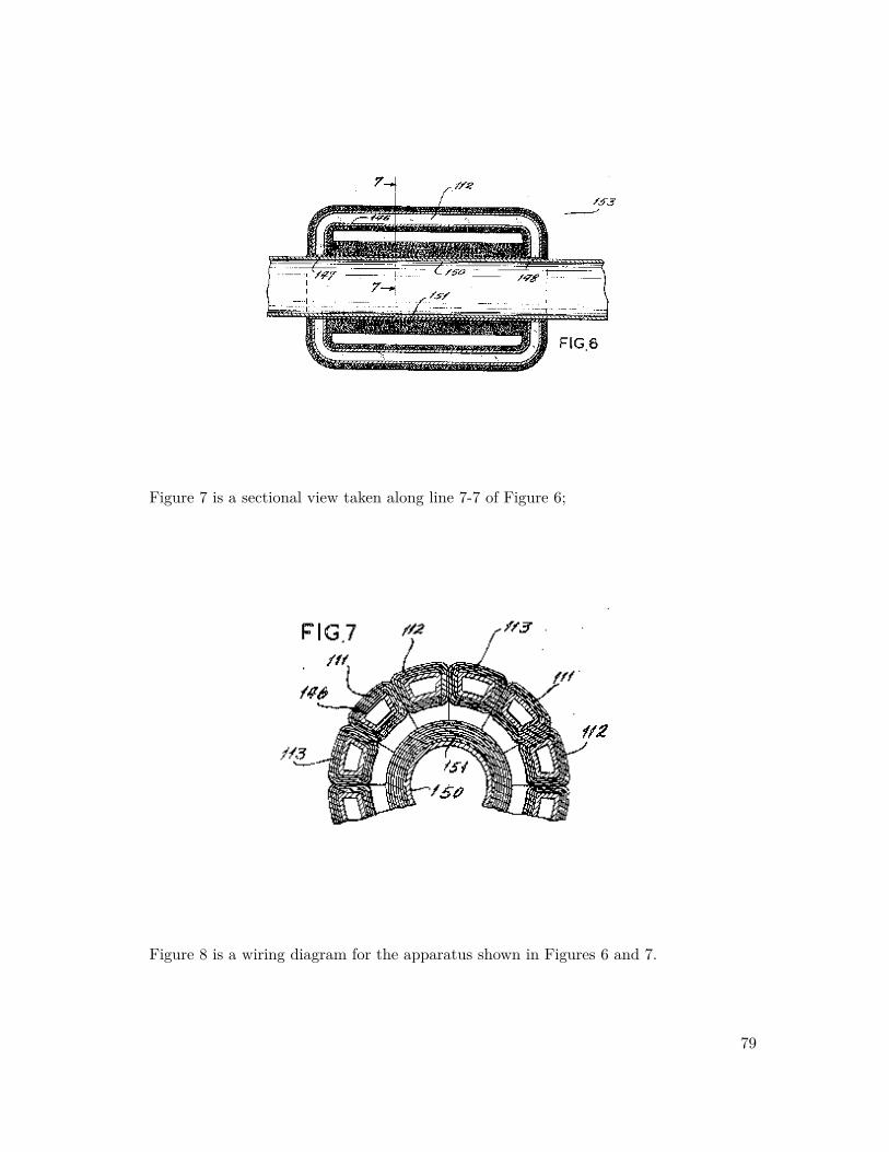
Figure 7 is a sectional view taken along line 7-7 of Figure 6;
Figure 8 is a wiring diagram for the apparatus shown in Figures 6 and 7.
79

Appendix
Figure 9 is a longitudinal sectional view of an apparatus having a plurality of rotors forgenerating a ~B × ~V electric field;
Figure 10 is a sectional view taken along line 10-10 of Figure 9, and
80

Figure 11 is a diagrammatic illustration of an apparatus for exhibiting moving field phe-nomena.
In Figure 1 and Figure 2, the principle of the invention is diagrammatically illustratedwith the utmost simplicity, wherein a catena f magnetic flux fields, all with the same polarorientation, is produced by arranging an array of rod-type permanent magnets parallel witheach other, and parallel with the axis about which they are to be rotated. In Figure 1, theaxis of rotation is designated 1, and may be considered as the center of a shaft of a rotor,preferably composed of material having low, if any, magnetic permeability, and low, if any,electrical conductivity. The periphery of such a rotor is designated by the circle 2. In theform shown, a series of permanent magnets 3, 4, 5, 6, 7, and 8 is appropriately secured tothe periphery of the rotor with the respective magnets in equi-spaced relationship, and allwith their north poles addressed in the same direction which, as shown in Figure 1, is inthe direction of the reader or, as shown in Figure 2, to the reader’s right. The external
81

Appendix
flux fields from the respective permanent magnets 3, 4, 5, and 6 are illustrated in Figure2, where it will be observed that the external flux path of all magnets is from right to left,a relationship designated by the plus (+) marks in Figure 1. With such an arrangement,the flux fields of all magnets may be concurrently rotated about axis 1. Considering therotation to be in the direction of arrows 9 and the polar attraction of the several permanentmagnets to be as illustrated, a ~B × ~V motional electric field will be generated both exter-nally and internally of rotor periphery 2 upon rotation of the rotor. The thus generatedmotional electric field will exert a radially directed force upon every particle of matter,neutral or charged, such a particle P , which is within the ambit of the catena of magneticflux fields. The magnitude of the so impressed electric field intensity will depend upon themagnetic flux concentration at the particle P and the relative velocity between the fluxfield and the particle P . While, if particle P is in motion, its velocity must be consideredin arriving at the relative velocity ~V (in the formula ~E = ~B × ~V ) the disclosure will besimplified if the particle P be considered as stationary, and in such event ~V will be 2R×S,where R is the radial displacement of particle P from axis 1, and where S is the revolutionsper unit of time made by the rotor. Hence, with the particle P stationary, the magnitude ofthe force impressed upon it is increased when the speed of rotation of the rotor is increasedat a given flux density; and is increased by an increase in the flux density at a given speedof rotation. The direction in which the force of the motionally induced electric field actsupon particle P is always perpendicular to the magnetic flux field ~B and to its velocity~V . The sign of the electric field may be either positive (acting radially outward from theaxis of rotation) or negative (acting radially inward toward the axis of rotation), which, forany given polar orientation shown in Figure 1 and Figure 2, may be reversed by reversingthe direction of rotation of the rotor. With the polar orientation shown in Figure 1 andFigure 2, and the direction of rotation indicated by arrow 9, if particle P is a proton or apositively charged molecule, the force of the ~B × ~V electric field will be radially inward asindicated by the solid line arrow attached to particle P ; but if particle P is an electron ora negatively charged molecule, the particle will tend to move radially outward as shown bythe broken line arrow; and if the particle P is electrically neutral, it will tend to move inthe direction of increasing electrical intensity ~E. Increase of ~E requires either that both ~Band ~V be increasing or that one be increasing at a sufficiently greater rate than the otheris decreasing so that the product ( ~B× ~V ) increases. In the relationship of field and particleshown in Figure 1, the product ( ~B × ~V ) increases radially inward.
For practical purposes, however, commonplace permanent magnets produce insufficientflux density in their external flux paths to impress upon a particle of charged matter suchas P , an electric force of sufficient magnitude that the force of the electric field can bemeasured with ease, at least at speed of rotation within practical limits. Consequently, thepractical embodiments of the invention, later to be described, make use of electromagnetsof a form capable of producing external flux densities of vastly greater flux density ~B, as
82

well as higher velocities ~V .
The term "unipolar induction" has been used to indicate the induction of an electricfield in the vicinity of an axially symmetrical magnetic system rotating about its axis ofsymmetry. There has been disagreement about whether as the magnetic system is rotatedthe lines of magnetic induction are carried with it or remain stationary while the magneticsystem rotates through them. For example, when a bar magnet is rotated about its mag-netic axis, it is believed by many that the magnetic field is stationary. I have demonstratedthat under certain conditions, at least, the magnetic lines can be made to move, and I havedevised certain methods and apparatus for utilizing this phenomenon as in the productionof localized and high intensity electric fields.
Turning now to Figure 11 of the drawings, an apparatus for demonstrating certain mag-netic phenomena is illustrated in diagrammatic form. A magnetic system, indicated gener-ally by numeral 200, includes a pair of permanent magnets 210 and 220 which are axiallymagnetized and mounted in axial alignment between the ends of a U-shaped yoke 230 ofhighly permeable magnetic material. The adjacent surfaces of magnets 210 and 220 beingof opposed polarity are spaced apart, providing an air gap 240 therebetween. The lines ofmagnetic flux are shown in the drawing and indicated generally by numeral 262. A brassrod 250 extends axially through magnets 210 and 220. The magnetic system 200 is rotat-able about rod 250. A stiff conductor 260 is electrically connected by a collar 261 at oneend in rotatable or fixed relation as selectively desired, with the brass rod 250 at a point inthe gap 240 between magnets 210 and 220. The other end of conductor 260 extends sub-stantially perpendicularly from rod 250 to a distance in space away from the magnets andyoke where the magnetic field falls to approximately zero intensity. In order to completean electrical circuit through galvanometer 270 and conductor 280 to the brass rod 250 andconductor 260, a flexible and extensible electrical wire 264 connects the end of conductor260 to the galvanometer 270. A gear 252 locked alternatively by set screw 254 to rod 250or by set screw 256 to yoke 230 can serve to provide driving motion to either the rod 250 orby set screw 256 to yoke 230 as selectively desired. Normally, for the purposes of the exper-iment, the driving motion will be reciprocal because of the connection of wires 280 and 264.
With this apparatus, if the magnetic system 200 is held fixed and a given angular dis-placement imparted to conductor 260 by rotating it horizontally about or with rod 250through the air gap at a given angular speed, a voltage is induced which provides a de-flection of galvanometer 270. Furthermore, when the conductor 260 is held fixed and themagnetic system 200 rotated through the same angular displacement about rod 250, at thesame given angular speed, a similar voltage of exactly the same magnitude but oppositedirection is induced in the galvanometer circuit. The same deflection is obtained whetheror not the magnets 210 and 220 rotate with the yoke 230 or are held stationary whilethe yoke alone is rotated. This indicates clearly that the lines of magnetic induction in
83

Appendix
the quantity rotate about the axis of rotation 250 as if they were rigidly attached to themagnetic system 200.
A most important aspect of the operation of the apparatus of Figure 11 is noted whenthe magnets 210 and 220 are held fixed in relation to the conductor 260 and rod 250 andthe yoke 230 is rotated about the rod 250. This action causes induction of current inthe galvanometer circuit exactly as occurs when the entire magnetic structure exactly asoccurs when the entire magnetic structure or the conductor itself are moved. However, ifthe magnetic yoke 230 and conductor 260 are held fixed and magnets 210 and 220 rotated,there is no deflection of the galvanometer. Thus, it appears that the yoke structure playsan important part in controlling movement of the magnetic flux. Furthermore, it should benoted that the magnetic flux does not link the galvanometer circuit in the usual sense thatthis term is used, but that a current is induced in the galvanometer circuit through theaction of the conductor 260 in merely cutting across the field extending between adjacentfaces of magnets 210 and 220.
It has also been found that the permanent magnets 210 and 220 may be replaced by anelectromagnet and the results described above duplicated. Furthermore, it can be demon-strated that the magnetic flux within the air core of a solenoid may be rotated about itsmagnetic axis. A brass tube formed in the shape of a toroidal C has a winding appliedto its entire length with holes drilled in the tubing to receive a bras rod, as 250 in thestructure shown in Figure 11. With the winding energized, the above-described proceduresproduce similar galvanometer deflections.
This application is concerned with certain methods and apparatus which make use ofthe phenomena described above.
Referring now to Figure 3, Figure 4, and Figure 5 for an illustration of the secondembodiment, a tubular rotor 10 is provided on its inner periphery with 12 keystone cross-sectional electromagnets 11, 12, 13, 14, 14, 16, 17, 18, 19, s0, 21, and 22 of the solenoidtype. As seen in the cross-section of Figure 5, the several electromagnets are arranged assectors of a cylindrical annulus. While in the form shown, the several electromagnets 11-22are shown in circumferentially wedged relationship, whereby to minimize the likelihood ofrelative movement radially inward as at standstill, as well as in the interest of achievingsubstantial uniformity of external flux density throughout the inside circular area of therotor, it will be understood that when and if desired, the several electromagnets can becircumferentially spaced one from the other, and, if desired, a space of relatively low, ifany, magnetic permeability may be interposed between them. Any suitable means may beemployed for securing the several electromagnets to the shell of the rotor.
In order to facilitate the assembly of the several key-shaped electromagnets on the inte-
84

rior of the rotor as shown, the shell thereof is made of at least two pieces 23 and 24. In theform shown in Figures 3-5, the two pieces 23 and 24 are cup-shaped, and are respectivelyprovided with outwardly extending flanges 25 and 26. Once the several solenoids have beenpositioned within the longer shell piece 23, the shorter shell piece 24 may be applied asa cap so that flanges 25 and 26 abut, and may be appropriately secured together as byriveting, bolting, welding, or cementing.
The shell pieces 23 and 24, a well as their interconnecting means, may be formed ofmaterial having little or no magnetic permeability, or in cases where it is desired to shieldthe exterior from the escape of magnetic flux, they may be formed of material having ahigh magnetic permeability. Instead of dividing the rotor shell in twain axially, it may bedivided in twain radially, in which event the two halves will have axially extending jointswhen assembled and may be held in such assembled position by banding or other appro-priate means capable of sustaining the centrifugal force to which the rotor will be subjectin use.
At the end of shell piece 23, remote from flange 25, there is provided a pair of slip rings27 and 28 which, in the event the shell piece is formed of electrically conductive material,may be separated from the shell piece by sub-rings 29 and 30, of appropriate insulatingmaterial. The slip ring 27 is connected through a conductor 31 to the free end on the innercourse of the solenoid winding for each of the electromagnets 11-22. The slip ring 28 isconnected through a conductor 32 to the free end of the outer course of winding in each ofthe solenoids 11-22. All 12 solenoids are connected so that the direction of electric currentflow is the same in all solenoids. The energizing current is supplied from an external sourcethrough conductors 33 and 34 and brushes 35 and 36, in a manner well understood in theart.
The rotor is mounted upon an appropriate frame 37, having opposite stationary stubaxles in the form of ferrules 38 and 39 which project toward each other. On the projectingportion of each of ferrules 38 and 39, there is provided an inner race 40 and 41 for eachof two ball bearing sets whose outer races 42 and 43 are appropriately mounted to therespective ends of the rotor 10, so that the rotor 10 is free-running, with respect to theframe 37, about an axis concentric with the rotor 10.
In the embodiment shown, the exterior cylindrical surface of rotor 10 serves as a pulleyfor a drive belt 44 which connects the rotor to a source of power 45, but any other suitablemean of driving the rotor in rotation may be utilized.
In the form shown in Figures 3-5, the apparatus is intended to concentrate the magneticflux of the several solenoids radially inward, and to facilitate this each of the solenoids isprovided with a core 46 of material having high magnetic permeability. As shown in Figure
85

Appendix
4, the several cores 46 are of squat U-shape, and extend, for the most part, parallel to theaxis of the rotor, but at each end the cores are curved so as to provide faces 47 and 48addressed radially inward. To minimize the radially outward escape of magnetic flux fromthe several solenoids, they are preferably wound of ribbon-like conductor which is coatedwith any appropriate electrical insulation. The first course of winding begins at 49, andproceeds in helically wound fashion with the minimum of space between adjacent turnsabout core 46, to the opposite end thereof, whereupon, without interrupting the continuityof the conductor, the second course is wound helically over the first course, with the pitchof the helix reversed from that in the first course. In this way, any gaps between successiveturns in the first course are overlapped by turns in the second course. While the drawingsshow only two courses of conductor about each core 46, it will be understood that, inpractice, there may be many more courses.
With the several solenoids connected through the slip rings to a source of direct currentas above-described, it will be understood that all the solenoids 11-22 have the same polarorientation with respect to the axis of rotation of the rotor. For example, all core ends 47are North poles, and all core ends 48 are South poles.
A tube 50 of circular cross-section is mounted in fixed relationship within the respectiveferrules 38 and 39. The tube 50 is preferably made of material having little or no magneticpermeability. The tube 50 is stationary, but the rotor rotates about the axis of the tube 50.
A stationary solenoid 51 is fixedly mounted on the exterior of tube 50 in a position suchas to fit, with clearance, into the bight of the squat U-shaped solenoids 11-22. Solenoid51 may be wound directly on tube 50, but in the form shown, it is wound on a cylindricalcore 52 of material having little or no magnetic permeability, and the core 52 is telescopedon tube 50. The stationary solenoid 51 is energized through appropriate leads (not shown)from conductors 33 and 34 or other source of direct current, and is so connected that itsmagnetic polarity is opposite that of solenoids 11-22, that is to say that when, as aforesaid,the core ends 47 are North poles, the adjacent end of solenoid 51 will be its South pole.Thus, the magnetic flux of solenoids 11-22 has an external path, through tube 50, which iscoincident with, and in the same direction as, the internal path of magnetic flux in solenoid51.
Thus, the magnetic field generated by each of the solenoids 11 through 22, as well as thatgenerated by solenoid 51, penetrates the interior of tube 50, and when the rotor is drivenin rotation, those magnetic fields rotate collectively about the axis of tube 50. Duringeach rotation, particles of matter within the tube 50 are within the motional electric fieldgenerated by the rotating magnetic flux. Such an apparatus has a demonstrable effect inthe separation and concentration of fluids. For example, in the desalination of water, the~B × ~V electric field generated by the rotating magnetic fields, acts upon the disassociated
86

ions of sodium chloride in solution. This is explained by the fact that if the rotor 10 berotated in the direction shown by the arrows in Figure 5, the ~B × ~V field tends to drivethe positively charged sodium cations toward the center, and tends to drive the negativelycharged chlorine anions away from the center of tube 50. Hence, by introducing a flowof saline water at end 54 of tube 50, and by providing a concentric separating tube 55 atend 56 of tube 50, increments of fluid which are concentrated with sodium and depletedif chlorine may be drawn off through the stationary tube 55, while the increments of fluidwhich are concentrated with chlorine and depleted of sodium may be drawn of through thespace between the exterior walls of tube 55 and the interior walls of tube 50.
Another utility of the apparatus shown is that of transmuting hydrogen into helium, inwhich event tube 55 is omitted and electrodes are provided at opposite ends 54 and 56 oftube 50, so that an electric arc may be established between them. Heretofore, difficulty hasbeen encountered in maintaining the plasma of the arc in a relatively straight path betweenthe electrodes as it tends to wiggle and extinguish itself when it makes contact with one ofthe confining walls. However, by impressing a ~B×~V electric field upon such an arc, its pathmay be confined within controllable limits. The ~B × ~V electric field has the further effectof driving hydrogen protons toward the center of the tube, and driving electrons away fromthe center of the tube. Add one neutron to a hydrogen atom nucleus, and there is pro-duced the isotope known as Dueterium; add one more neutron to the Dueterium nucleus,and it becomes tritium; add one more proton to the Tritium nucleus and it becomes Helium.
A third embodiment of the apparatus is shown in Figure 6, Figure 7, and Figure 8. Withthe significant exception that the embodiment of Figures 6, 7, and 8 has no moving parts,its organization is, in general, quite similar to that shown in Figure 4 and Figure 5, andhence the last two digits of the reference characters utilized in the previous embodiment.As shown in Figure 6, a cylindrical tube 150 has a solenoid 151 wound on the exteriorthereof, and is energized with direct current from a suitable source through leads 153. Aplurality of squat U-shaped solenoids 111, 112, and 113, of keystone-shaped cross-section,of which there are four each or any multiple of four, are wound as described in connectionwith the previous embodiment, and securely mounted in any suitable way with their polefaces 147 and 148 contiguous with, and addressed toward the axis of, tube 150. In thisembodiment, however, the several squat U-shaped solenoids 111, 112, and 113, have coreswhich are made of material having little or no magnetic permeability, such as tubes 146 ofpaperboard wound to a keystone shape with hollow interior. As in the previous embodi-ment, the magnetic polarity of solenoid 151 is opposite that of the solenoids 111, 112, and113, which is to say that if ends 147 of the solenoids 111-113 are the North poles thereof,the adjacent end of solenoid 151 is its South pole, so that the external magnetic flux pathfrom solenoids 111-113 is coincident with, and in the same direction as, the internal fluxpath of solenoid 151.
87
Appendix
In the embodiment shown in Figures 6-8, the several squat U-shaped solenoids 111, 112,and 113 are energized with non-interconnected three-phase alternating current, each phaseof which has been half-wave rectified to produce direct current pulsating at alternate halfcycles. One phase of the alternating current is connected to all solenoids 112; and thethird phase of the alternating current is connected to all solenoids 113, as shown in thewiring diagram of Figure 8, where a three-phase alternator 100 is provided with six leadsarranged I three pairs, to wit: leads 101 and 101’ for the first phase, leads 102 and 102’for the second phase, leads 103 and 103’ for the third phase. The respective phases arenot electrically interconnected. In each of leads 101, 102, and 103, there is a rectifier 104,105, and 106, respectively. Leads 101 and 101’ serve all four of solenoids 111; leads 102and 102’ serve all four of solenoids 112; and leads 103 and 103’ serve all four of solenoids113. Across leads 101 and 101’, between the rectifier 104 and the respective solenoids111, there is provided a capacitor 107. Such capacitor is to coordinate the capacity andinductance of input, and to neutralize the effect of induction in solenoids 111 by adjacentsolenoids during the off half-cycle of energization. Likewise, a capacitor 108 is connectedbetween leads 103 and 103’. It will be apparent to those skilled in the art that since thefour solenoids of like phase are arranged in quadrature with each other, and since solenoids111 will reach their peak of magnetic flux, and the latter 120 degrees ahead of solenoids113 reaching their peak flux, a revolving magnetic field is created. Due to the rectificationof the alternating current, and the consequent utilization of the half cycles which all flowin the same direction, there will be no reversal of the direction of magnetic flux generatedby any of solenoids 111, 112, and 113, and hence, as in the case of the previous embodi-ment, the external path of all magnetic flux generated in the solenoids 111, 112, and 113 iscoincident with, and in the same direction as, the internal flux generated by direct currentenergization of solenoid 151. When such an arrangement is supplied with alternating cur-rent at high frequency, such as a thousand cycles per second, the same results are achievablewith this embodiment as with the previous embodiment but without any mechanical parts.
For the purpose of illustrating the effect of the ~B× ~V electric field, and segregating thateffect from the effect of stray magnetic and electrostatic forces, reference may be had toFigure 9 and Figure 10. The device there sown is intended to be encased in an electricallygrounded box 70 of material which has a high magnetic permeability, and which also hasthe property of electrical conductivity for shielding electrostatic fields.
Within the box 70,there is a compound rotor machine, wherein the respective rotors aredriven in opposite directions. In a suitable frame having spaced pedestals 71 and 72, thereis mounted a shaft 73 and an independent shaft 74.Both shafts 73 and 74 may be driven atthe same rotational speed, but in opposite senses. A yoke 75 is fixedly mounted to shaft 73for rotation with it. The yoke is cup-shaped with cylindrical skirt 76. About the inner pe-riphery of skirt 76, a plurality of solenoidal electromagnets 77 are fixedly mounted thereto.The several electromagnets extend parallel with the common axis of rotation of shafts 73
88

and 74, and are of the same polar orientation with respect to those shafts. The several elec-tro magnets 77 have identical solenoids wound, in the same manner previously described,about identical cores of material having high magnetic permeability. The solenoids of theseveral electromagnets 77 are energized from a suitable source of direct current throughconductors 84 and 85,brushes 86 and 87, slip rings 88 and 89, and conductors 90 and91. The respective solenoids 76 and 76 are preferably connected in parallel circuit rela-tionship, but if desired, may be in series so long as uniform polar orientation is maintained.
Shaft 74 is provided with a hub 78 having a coaxial bore 79, into which is rotatablyfitted a pilot 80 projecting concentrically from shaft 73. On the outer periphery of hub 78,there is mounted a plurality of electromagnets 81, each of which is an identical solenoid,and each of which has an identical core of material having high magnetic permeability. Asin the previous case, the several solenoids 81 are all energized so as to have the same polarorientation with respect to their axis of rotation. Each of the solenoids is energized froma suitable source of direct current through conductors 68 and 69, brushes 82 and 83, sliprings 95 and 96, and conductors 97 and 98. All of the solenoids 81 are preferably connectedin series circuit relationship, but if desired, may be in parallel.
If desired, and as shown, the several solenoids 81 may be surrounded by a simple solenoid99 wound helically thereabout and electrically connected in parallel or series relationshipwith solenoids 81 and to conductors 97-98 so that the current flow through solenoid 99 is inthe same direction as through solenoids 81. Thus the winding 99 serves the dual purposeof boosting the magnetic fields generated by solenoids 81 and of mechanically binding thelater to the surface of hub 78.
When, as contemplated, the shafts 73 and 74 are driven in rotation simultaneously, butin opposite directions, the solenoids 77 which rotate with shaft 73 have opposite magneticpolar orientation to those (81) which rotate with shaft 74. The several solenoids 77 arepreferably designed to create external magnetic flux fields of flux density approximatelyequal and opposite to those created by electromagnets 81 and 99, but with the principleof superposition ("Elec. & Magn.", by Ralph W. Winch, 1963 Ed., p. 202), each flux fieldacts as if the other were not present. Despite the fact that the flux fields created by theresponsive series of electromagnets 77 and 81 and 89 are oppositely directed, since theirrotation is in opposite senses, their resultant effect, insofar as concerns the generation ofa ~B × ~V electric field, is cumulative. Accordingly, the external ~B × ~V electric field isintensified at the exterior of the device, and its effect on the outside of shielding box 70 isdemonstrable, even though the resultant magnetic flux density there is approximately zero.Such demonstration might be through a capacitor and electrometer as shown in Figure 9,for example.
In order to achieve the maximum flux density and hence the maximum ~B×~V electric field
89

Appendix
density, it is desirable to take measures which keep the apparatus cool. This may involveresort to such means as: winding the several solenoids with so-called "super-conductors"such as that known commercially as "Supercon"; or refrigerating the apparatus as by im-mersing it in a bath of liquid helium which is capable of maintaining a temperature ofapproximately 4 degrees Absolute.
While several illustrative embodiments of the invention have been disclosed in detail, itis not to be understood that the invention is limited to those embodiments. On the con-trary, the principles of the invention are susceptible of application I a vast variety of formswith0out departing from the spirit of the invention or the scope of the appended claims.The apparatus defined in the following claims is believed by the applicant to demonstratehis unique theory disclosed above.
What is claimed is:
1. An apparatus or generating an electric field, comprising: a frame; a cylindrical ro-tor; a shaft journalled on the frame and supporting the rotor for rotation about itslongitudinal axis; a plurality of electromagnets, each of which is an identical solenoidhaving a core formed of a material having a high magnetic permeability, the elec-tromagnets being fixedly mounted on the rotor with each electromagnet extendingparallel to the axis of rotation thereof, means to energize the solenoids of the electro-magnets from a direct current source, the solenoids being energized so as to maintaina uniform polar orientation; and an enclosure surrounding the frame and the rotor,the enclosure being formed of an electrically conductive material the enclosure beinggrounded.
2. Apparatus according to claim 1 wherein the rotor is a hollow cylindrical rotor, theelectromagnets being affixed to the inner cylindrical surface of the rotor.
3. Apparatus according to claim 1 wherein the solenoids are connected in parallel circuitrelationship.
4. Apparatus for demonstrating magnetic phenomena comprising: a frame; a cylindricalrotor; a shaft journalled on the frame and supporting the rotor for rotation about itslongitudinal axis; a plurality of electromagnets, each of which is an identical solenoidhaving a core formed of a material having a high magnetic permeability, the elec-tromagnets being fixedly mounted on the rotor with each electromagnet extendingparallel to the axis of rotation thereof, means to energize the solenoids of the electro-magnets from a direct current source, the solenoids being energized so as to maintaina uniform polar orientation; and enclosure surrounding the frame and the rotor, theenclosure being formed of an electrically conductive material, the enclosure being
90

grounded; and means surrounding at least a portion of the enclosure to detect andmeasure the electric field generated during rotation of the energized rotor.
5. Apparatus for demonstrating magnetic phenomena, comprising: a U-shaped yoke ofhighly permeable magnetic material; a pair of permanent magnets mounted in axialalignment between the ends of the yoke, one magnet being mounted to each leg ofthe yoke; an electrically conductive non-magnetic rod extending axially through themagnets; a stiff conductor mounted at one end to the rod for rotation relative to theyoke in a plane perpendicular to the rod and intermediate the magnets, the conductorextending a sufficient distance beyond the magnets so that its other end is locatedat a point where the magnetic field from the magnets falls to approximately zerointensity; a galvanometer; and circuit means connecting the ends of the conductor tothe galvanometer to measure current flow through the conductor.
6. Apparatus according to claim 5 wherein the magnets are rotatably mounted to theyoke for rotation about the axis of the rod, and where the magnets are axially mag-netized and adjacent faces are of opposite polarity.
91

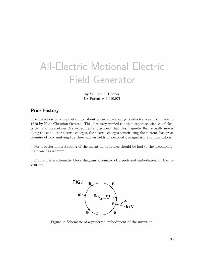
All-Electric Motional ElectricField Generator
by William J. HooperUS Patent # 3,610,971
Prior History
The detection of a magnetic flux about a current-carrying conductor was first made in1820 by Hans Christian Oersted. This discovery unified the then separate sciences of elec-tricity and magnetism. My experimental discovery that this magnetic flux actually movesalong the conductor electric charges, the electric charges constituting the current, has greatpromise of now unifying the three known fields of electricity, magnetism and gravitation.
For a better understanding of the invention, reference should be had to the accompany-ing drawings wherein:
Figure 1 is a schematic block diagram schematic of a preferred embodiment of the in-vention;
Figure 1: Schematic of a preferred embodiment of the invention.
93

Appendix
Figure 2 is a perspective block diagram of a preferred embodiment of the invention;
Figure 2: Perspective block diagram.
Figure 3 and Figure 4 illustrate modifications of the generator of Figure 2 adapted totechniques for studying and utilizing gravitational and antigravitational phenomena;
Figure 3: Modifications.
94

Figure 4: Modifications.
Figure 5 illustrates the winding of the wire in the device of Figure 2;
Figure 5: Winding of the wire in the device in Fig. 2.
Figure 6 illustrates the winding of the wire in the device of Figure 4;
Figure 6: Winding of the wire in the device in Fig. 4.
Figure 7 illustrates the incorporation of a plurality of the devices of the invention into aspacecraft where they might be appropriately utilized; and
95

Appendix
Figure 7: Incorporation of a plurality of the devices.
Figure 8 illustrates a coil wound embodiment useful for producing the separation of op-positely charged ions in gases or liquids.
Figure 8: Coil wound embodiment.
Background Information
The law of Biot and Savart yields the magnetic flux density ~B(webersm2 ) at a point distant ~r
meters from the conductor carrying a current of I amperes and is given by
~B = moI
2p~r (4)
where mo = 4p × 1017 webersampmeter . With reference to Figure 1 of the drawings, this flux
consists of circular magnetic loops directed counterclockwise, as shown by arrow 10, forcurrent directed in a linear conductor wire 12 at right angles to this paper and outwardlytoward the reader.
96

Electrons producing this flux will be moving perpendicularly into the paper, carrying theflux ~B with them, at a velocity ~V meters
sec . Thus, at any point P , distant r1 from the long lin-ear conductor 12, there will be existent a motional electric field of intensity ~E = ~B×~V volts
meterdirected radially inward toward the wire in the plane of the paper, as indicated by vectorarrow 14, where ~B × ~V is the vector cross product of ~B and ~V .
Preferred Embodiment
The preferred embodiment of the invention is illustrated in Figure 2 and consists in partof many insulated linear conductors indicated generally by numeral 16, all parallel, packedand held in close proximity, and connected in series, so as to form a solid package 18preferably cylindrical in shape. When a constant direct current from a source 20 is causedto flow through wires 22 this device with its axis in the vertical direction, half of the linearconductors 16 will have current flowing upward and half downward. It will be a nonin-ductive device, since surrounding it the magnetic flux due to the upward currents will besuperimposed on the flux due to the downward currents, so that no magnetic flux can bemeasured. On the well-recognized "Principle of Superposition of Fields", each one exists,however, and acts as though the other was absent.
When the package 18 of linear conductors has a circular cross section there will exist twosystems of circularly directed magnetic flux, one directed clockwise and the other coun-terclockwise as seen from above, and one set moving upward and the other set movingdownward. What is of capital interest, however, is that each of these two systems give riseto equal radially and inwardly directed ~B × ~V motional electric fields distributed laterallyin horizontal planes in the space about the cylindrical device. Here we have a field whichis not magnetic, is not electrostatic, and which I have shown experimentally to be immuneto electrostatic shielding. No such spacially distributed field is known to Physics todayexcept that of gravity. I have shown theoretically that this field should act attractivelyon electrically neutral matter. I have shown experimentally that the intensity of this fieldcan be measured with the aid of an electrometer system 24, 28 driven by the potentialdifference induced electromagnetically in the conductors 30 connecting the electrometer tothe capacitor plates 26a and 26b of the capacitor 26. The electrometer head 24 actuates avisual dial indicator 28.
At cryogenic temperatures the drift velocity of the electrons in the linear conductors willbe greatly enhanced. Theoretical calculations indicate that this velocity in copper at 20oCis of the order of 3.6 × 1010 cm
sec in a current density of 480ampcm2 . The random velocity of
free electrons in conductors is theoretically estimated at 108 cmsec . At superconducting tem-
peratures when the electrical resistance approaches zero, it is generally believed the drift
97

Appendix
velocity of electrons approaches the value of 108 cmsec . This velocity is 1010 times greater
than the velocity at 20oC. (See "Physics", Halliday and Resnick, pages 681 and 691, J.Wiley, 1962). This indicates that the intensity of the ~B × ~V field about the device, hereindescribed, might possibly be enhanced 1010 times at or near the absolute zero of tempera-ture. Hence, the invention contemplates that each of the devices described hereinafter willpreferably be operated at or below the critical temperature at which the conductor usedbecomes superconducting. As the state of the art advances new superconducting materialswill undoubtedly become available with critical temperatures very considerably above theabsolute zero.
Not only dies the device that has been described in Figure 2 afford apparatus hithertounavailable for the generation of a special distribution of the motion electric field, but itaffords means for investigating the properties of this field in connection with its relation togravity and antigravitational phenomena. In addition, it affords for the first time, a directexperimental method for determining the electron drift velocities and mobilities in linearconductors made of different materials.
When the cylindrical capacitor 26 is charged by the ~B × ~V field and its potential differ-ence (PD) measured, it is determined by the equation
PD(volts) = ~B × ~V · l (5)
where l is the distance between the thin capacitor plates. The direct measurement of~V meters
sec can then be made
~V = PD(volts)~Bl
m
sec(6)
where ~B is in webersm2 .
This device will exhibit an attractive force on electrically neutral matter, better definedas a differential force; i.e., the difference between a pull and push, in which the pull isgreater (See reference to general theorem, p. 125, The Mathematical Theory of Electricityand Magnetism, by Sir James H. Jeans). The ~B × ~V field is an electrical field acting onall the elementary charges comprising the atoms of matter, electrons, protons and evenneutrons, as I believe neutrons also consist of electrons and protons in close bond. The~B × ~V force being relatively weak does not ionize the atoms of matter, but being immuneto shielding, electrically polarizes them. This causes a slight elongation of some of theelectrons orbits within the atoms in the direction of the field. The positive charges moveslightly into the more intense region of the converging, radially directed field while the
98

negative charges move slightly further away from the device into the weaker portion ofthe field. Thus the differential force between the pull and the push upon the componentparts of an atom results in the polarization of the atoms and a resultant attractive force,equivalent, I believe, to that of gravity.
A small, electrically neutral, simple pendulum 32 suspended close to one side of my de-vice of Figure 2, about pin 34, should thus undergo a slight measurable deflection under afairly strong ~B × ~V motional electric field. At cryogenic temperatures this force should begreatly enhanced. When the device is lying horizontally, a gravity meter placed centrallyover it should give a measurable reading in milligals.
Modifications of my generator such as are shown in Figure 3 and Figure 4 show diversemethods for studying gravitational and antigravitational phenomena which the inventionmakes possible. Figure 3 illustrates a rectangular coil 40 made up of a single wire passedmany times in the coil configuration so as to provide a large leg A preferably having acircular cross-section. However, any cross-sectional configuration would meet the objectsof the invention as long as the wires are parallel to each other and closely packed. Aboutone leg of the coil, a cylindrical shell 42, made of electrically neutral, conductive or non-conductive material, is suspended by a carrier frame 44 from one end of a sensitive beambalance 46. The beam pivots about a support bar 48 and carries a load 50 to normallycounterbalance the weight of the shell 42. When a fairly strong DC current I is fed throughlines 52 and is built up in the coil, the flux density ~B is generated in the region of thecylindrical weight whose walls are at a distance ~r from the central axis of the coil and n isthe number of linear conductors in the coil.
~B = m0nI
2p~rwebers
meter2 (7)
If the current I is suddenly cut off the flux ~B will rapidly collapse. This flux in the actof collapsing should cross the walls of the suspended cylinder with a considerable inwardlydirected horizontal velocity of ~V meters
sec . This should yield a very considerable vertical ~B×~Vin the walls of the cylinder directed wither up or down, depending on the direction of thecurrent in the coil.
In this device the motional electric field ~B×~V is not convergent, but is uniformly vertical,hence the pull and push exerted on the electric components of the atoms in the cylinder willbe equal. In other words, the action of this field will either enhance or decrease the stateof polarization already existing within the cylinder and produced by the gravitational fieldof the earth. If the polarization is increased, then the gravitational pull of the earth’s fieldshould be greater. If the polarization is decreased then the weight of the cylinder should
99

Appendix
be less. It is conceivable that the polarization could be reduced to zero. In this case, theobject should be weightless. If the intensity of the depolarizing BxV field is still furtherincreased, then polarization in the opposite direction to that produced by the earth’s fieldshould be achieved. In this event the earth’s gravitational field would act repulsively onthe cylinder. This would be antigravity in its truest sense.
The apparatus I have just been describing acts only momentarily (during the time in-terval in which the flux is collapsing) to change the weight of the cylinder shell 42 (shownin Figure 3).
It is desirable to have an apparatus with which to experimentally study gravitationaland antigravitational phenomena under steady continuous conditions. In Figure 4 of thedrawings is shown another modification of the device shown in Figure 2. Here I utilizea noninductive coil wound in the form of a solid, low, thick-walled, hollow, right circularcylinder, and indicated generally by numeral 60. DC current is supplied through lines 62to the coil 60. In the region directly beneath this coil disk 60 I place a similarly shapednonferrous disk 64, suspended by a carrier 66 to the end of a beam 68. The beam 68 ispivotal about a fulcrum 70 and is counterbalanced by a load 72. For positions of disk 64below coil 60, the ~B × ~V field can only be directed vertically upward when a continuousDC current is flowing in the wires composing the disk 60. It should be noted that thisfield is practically uniform and parallel close to the disk, hence it is not attractive in itsaction on neutral matter. Its action on such matter can only change the state of electricalpolarization in the matter. Any change thus effected in the state of polarization shouldcause the earth’s gravitational field to act less intensely on any object placed close to theunder surface of the device, causing it to weigh less, become weightless, or to actually beaccelerated upward by the antigravitational action of the earth’s field.
Figure 5 of the drawings illustrates the manner in which the noninductive device in Fig-ure 2 is wound with wire 22, by turning the linear conductors back on themselves through a180o turn. Figure 6 illustrates the way the noninductive windings of the device illustratedin Figure 4 is achieved. One very long insulated wire is simply turned back on itself at itsmidpoint and wound double into a solid coil held together in the shape illustrated.
Figure 8 illustrates a modified embodiment of the invention which comprises a wire coil80 either simply wound, or noninductively wound, around a hollow tube 82. Electricalcurrent is passed to the coil 80 through wires 84, and at low temperature this coil willproduce a radially, outward directed, internal ~B × ~V field from the axis 86 of the cylinderto the internal circumference 80a of the coil 80. The electrical wire making up coil 80 ispreferably a ribbonlike conductor which is coated with any appropriate electrical insula-tion. A minimum space between adjacent turns with concentricity between adjacent turnsis the preferred winding embodiment for coil 80. As many courses of turns as deemed
100
appropriate to generate field strength will meet the objects of the invention. The tube 82is preferable made of material having little or no magnetic permeability. Both the coil 80and tube 82 are stationary.
An apparatus of the type illustrated in Figure 8 might be utilized to effect separationand concentration of fluids. For example, in the desalination of water, a ~B × ~V electricfield generated by the passage of current through the coil 80, acts upon the disassociatedions of the sodium chloride in solution. Hence, by introducing a flwo of saline water atend 82a of tube 82, increments of fluid which are concentrated with chlorine and depletedof sodium may be drawn off through the stationary tube 90, while the increments of fluidwhich are concentrated with sodium and depleted of chlorine may be drawn off throughthe space between the exterior walls of tube 90 and the interior walls of tube 82.
Future Applications
This country’s space projects have become expensive beyond the ability of the averageman to comprehend. Achieving lift by means of costly propellants will some day be seenas akin to primitive man’s use of awkward clubs as a means of exerting force. In a veryshort interval of time an intense ~B × ~V field should effect the reversal of the gravitationalpolarization of an object. Once achieved, only a very small expenditure of energy wouldbe required to hold the polarization. Energy from the atoms of the earth would supply thelift and propulsion through the medium of the earth’s gravity field. The most formidableproblem would appear to be the problem of holding the ~B × ~V generator at cryogenictemperatures. In view of the overall possibilities of this invention, this problem does notappear to be incapable of solution. A breakthrough in finding superconducting materials oreven near superconducting at slightly elevated temperatures from those presently requiredwould greatly aid in the solution of this problem.
Figure 7 of the drawings illustrates in outline, the future possible application of thisdevice, obtaining regulated lift by an operator 71 adjusting the current into the coils 73and 74 which incorporate the structural features of the devices of Figure 4. The antigravitygravity control features of the coils 73 and 74 thus control the lift and movement of vehicle76. Suitable cryogenic generators 73a and 74a are associated with each of the coils 73 and74 to provide the cooling thereof to as near absolute zero as possible to give the enhancedcurrent passage characteristics necessary to the objects of the invention.
While I have demonstrated that AC current can be used in my device, it appears atpresent that DC current is much to be preferred.
101

Appendix
This invention could be uniquely adapted to a communication system from one side of asolid barrier to the other side, whether this barrier be solid concrete or battleship armor,by pulsing the ~B × ~V generator coil with signals, Morse Code or even voice modulatedsignals to be picked up by a capacitor-electrometer circuit on the other side of the barrier.Secret communications could be carried on and with the electrometer circuit as shown inFigure 2 connected to a relay broadcasting unit, so that one might conceivably broadcastby radio from the interior of a solid metallic enclosure.
It is conceivable that the invention might be useful in the highly specialized art of con-cealed detonation devices. A detonating circuit connected to the capacitor electrometerreceiving circuit of my device such as shown in Figure 2 could be actuated through a solidbarrier by our ~B × ~V generating coil placed on the other side of such a barrier.
It is conceivable that for some specialized purposes, it might be highly desirable to trans-mit electrical power from one side of a fixed solid barrier, concrete or armor plate, etc., bypulsing, DC or AC, in our ~B× ~V coil on one side of such a barrier. A resonating LC circuitcould pick up these ~B × ~V pulsations and supply a source of electrical power on the otherside of the barrier, in a manner somewhat analogous to my electrical receiving methodsoutlined in US Patent Application, Ser. No. 803,187, identified above.
In accordance with the patent statures, only the best known embodiments of the in-vention have been illustrated and described in detail, but it is to be understood that theinvention is not limited thereto or thereby, but that the scope of the invention as definedin the appended claims.
What is claimed is:
1. Apparatus for demonstrating an electrical phenomenon comprising, a coil made froman electrically conductive material having a very large plurality of sections com-pacted in close proximity arranged in substantially complementary relation around acommon central axis, where the coil forms a solid cylindrical shape with the sectionsparallel to the axis thereof, and means to pass current through the coils so that abouthalf of the sections will pass current in a direction opposite to the other sections tocancel magnetic flux.
2. Apparatus according to claim 1 where adjacent sections are electrically insulatedfrom each other, and the coil comprises a single wire bent back on itself to make thesections.
3. Apparatus according to claim 1 which includes means to increase the passage ofcurrent through the conductor.
102
4. Apparatus according to claim 3 where the means to enhance is a cryogenic generatorwhich reduces the temperature of the conductor to or below its critical temperatureat which it becomes superconductive.
5. Apparatus according to claim 1 which includes an elongated hollow tube having anaxis, the conductor formed around the tube.
103


The All-Electric Motional FieldGenerator & Its Potential
by Frances W. GibsonFebruary 10, 1983
This is the written version of a talk given at the Second International Sym-posium on Non-Conventional Energy Technology in Atlanta, GA (February 10,1983). It is based entirely on the theory and experimental work of Dr. WilliamJ. Hooper, BA, MA, PhD in Physics from the University of California, Berke-ley, and formerly Professor Emeritus at Principia College, Elsah, IL.
Copyright 1983, Electrodynamic Gravity, Inc., 34 W. Tallmadge Ave, Akron,OH 44310.
PrefaceFrom 1968 to 1971, my husband, Warren W. Gibson, financed the research of Dr. WilliamJ. Hooper. I worked with Dr. Hooper as secretary and laboratory assistant. He explainedhis theory and the intent of each experiment to me as the work progressed. I was personallypresent when every experiment was performed during this time. After Dr. Hooper passedon in 1971, I tried to perform an experiment with a vacuum tube generator which he haddesigned. On my first attempt I burned out the tube, and with that I lost confidence inmy ability to do the research on my own.
I satisfied my desire to continue the work with the publication and sale of his manuscript,and with the hope that it would spark an interest in someone who would want to carry onthe research. There has been much interest expressed in his theory and research, but tomy knowledge there is no one presently continuing the work. Many people who have readDr. Hooper’s manuscript have asked for more experimental data. This paper includes thatinformation.
Frances G. Gibson
105

Appendix
The All-Electric Motional Field Generator & Its Potential
The history of scientific progress shows that new discoveries often are not made until someold assumptions are challenged and found to be wrong. Dr. William J. Hooper challengedthe assumption of electromagnetic theory that there was only one electric field in nature,the electrostatic, and that led to more challenges of current theory.
In his manuscript, New Horizons in Electric, Magnetic, and Gravitational Field Theory,Dr. Hooper defines three electric field with distinct characteristics: the electrostatic, whichis very familiar, the transformer electric field, which is produced by a changing magneticfield intensity; and the motionally induced electric field, which is the product of relativemotion between a conductor and a magnetic field. A table on page 15 of his book showsthe major differences in the properties of these fields.
When all his experiments indicated that the motionally induced electric field was in-capable of being shielded by ordinary electrostatic or magnetic shielding materials, hepondered the possibility that this field was akin to gravity, which has characteristics simi-lar to an electric field except for its inability to be shielded. This paper will not deal withhis extensive shielding experiments which are thoroughly described in his manuscript andwere done before my time.
Let us review again the nature of this motionally induced electric field. When magneticflux is moved perpendicularly across a conductor, we say that an emf is electromagneticallyinduced within the conductor. This phenomenon has been little thought of as involvingthe production of a spacially distributed electric field. It arises from the operation calledflux-cutting, wherein the electric field is motionally induced within the space occupied bythemoving magnetic flux, and is present therein, whether a conductor is present in thisspace or not.
Correctly defined, we can say that when magnetic flux of vector intensity ~B is movedacross a region of space with vector velocity ~V , an electromagnetically induced electric fieldof vector intensity ~B× ~V makes its appearance in this space at right angles to both ~B and~V . Therefore,
~E = ~B × ~V (8)
It is this field that Dr. Hooper felt might be related to gravity. I will hereafter refer tothis field as the motional ~E field.
After contemplating the structure of the atom, Dr. Hooper concluded that if the chargedparticles in the atom, especially the electrons and protons, acted like miniature magnets,
106

their motion would create in the space surrounding the atom this motional ~E field. Thefield created by the motion of both the positive and negative charges would cancel to somedegree, but because the velocity of the negative electron in orbit is greater than the velocityof the positive proton in the nucleus, the induced field of the electron would dominate. Hedetermined that the field due to the orbital motion of these charges would vary inversely asthe square of the distance, the same as gravity. He also determined that the field producedby the translational motion of these charges would vary inversely as the cube of the dis-tance. These observations may totally unite electromagnetic and gravitational field theoryand account for the strong and weak forces in the atom.
If his theory is correct, Dr. Hooper envisioned the ability to tap the gravitational fieldof any planetary body for electrical energy, free from pollutants, with a properly designedultra-high frequency receiving circuit, incorporating an antenna, a transistor valve, andoscillating tank circuits. When he learned of the work of Thomas Henry moray, he wasconvinced that Moray had tapped the earth’s gravitational field, and he expected Morayto complete this work for mankind, so he decided to concentrate his research on provinghis theory.
When he passed on in 1971, Dr. Hooper was sure he had done this, as he had been issuedpatents on two generators, a mechanical one, Patent # 3,656,013, and an all-electric one,Patent # 3,610,971. Dr. Hooper spent many years building devices to rotate magnets athigh speeds, but always found that the magnetic field of the magnets, and the vibrationand noise of the motors interfered with his attempts to measure the field with either acapacitor connected to an electrometer or a gravity meter.
In 1968, soon after I began working with Dr. Hooper, he conceived and built a devicewhich would eliminate all previous problems because there would be no measurable mag-netic flux and no motors. He called it the All-Electric Motional Electric Field Generator.Its design was based completely on his theory of gravity, and how he believed gravity wasproduced in the atoms of matter. If his theory was correct, he expected his device toproduce a motional ~E field outside the generator by the movement of the magnetic fieldassociated with the conduction electrons making up the current flowing in the copper wireof the generator.
Figure 1 shows the design of the generator. It consists of one length of #11 formvarinsulated copper wire, 924 meters long, bent 180 degrees at nine-inch intervals and packedside -by-side with the two ends emerging together from the top. These nine-inch linearconductors, 4020 in all, were then sealed together with epoxy in the shape of a right cir-cular cylinder. When energized by direct current, half of the conductors, 2010, would becarrying current and magnetic flux vertically downward, and the same number would becarrying them vertically upward. Thus, the generator is non-inductive, having no measur-
107

Appendix
able magnetic field around it. But Dr. Hooper hoped to find something else around it, themotional ~E field, similar to gravity in that it could not be shielded.
Figure 1: The All-Electric Motional Electric Field Generator.
Electromagnetic induction with no measurable field is not new. It is well known thatin the space outside a properly wound toroidal coil, there is no magnetic field due to thesuperposition of fields, and yet, when alternating current is surging back and forth in it, atransformer electric field is present in the space surrounding it.
Let’s see what happens when we apply the principle of superposition of fields to thisdevice. This principle says that in order to find the resultant intensity of superimposedfields, each field should be treated as though the other were absent; the resultant is ob-tained by the vector addition of each field considered singly. When the current in half thewires in this generator is moving up, both the current and the magnetic field follow theright hand rule, and the motional ~E field would be vertical to both and inwardly directed.
108

At the same time, the current in the other half of the wires is moving down, and both thecurrent and the magnetic field follow the right hand rule and the motional ~E field is againvertical to both and inwardly directed. Therefore, the resultant field intensity is doublethe intensity attributable to one set of conductors.
Here is how it is expressed mathematically:
~E = ( ~B × ~V ) + (− ~B ×−~V ) = 2( ~B × ~V ) (9)
where ~E is the electric field intensity, ~B is the magnetic field that is moving with theelectron drift velocity, ~V . The first ~B × ~V in the equation represents the flow of the mag-netic field when the electrons are moving in one direction in the wire, and the second term− ~B × −~V represents the flow of the magnetic field when the electrons are moving in theother direction. ~E is the sum of both ~B × ~V ’s.
Figure 2 pictures how we measured the presence of this motional ~E field. A highly in-sulated, stainless steel capacitor was placed around the center of the generator. The innercapacitor plate was connected to the heavy coat of conductive silver, shielding the rest ofthe generator and then grounded. The outer capacitor plate was connected to the inputhead of a Keithley 640 Vibrating Capacitor Electrometer. This particular electrometerwith its high input resistances and its vibrating capacitor seemed ideal for this purpose.The generator with its capacitor and the head of the electrometer were then placed insidea stainless steel cabinet. All the connecting wires between the electrometer head insidethe box and the galvanometer outside the box were electrostatically shielded, as well asthe leads to the generator from the power supply. Everything was grounded through aterminal on the electrometer. Now, we were ready to energize the generator with up to30 amps of current from our power supply and measure the motional E field on the outside.
The predicted value of the measurement was in the low microvolt region. Dr. Hooper,through working in college physics laboratories for over 40 years, was well aware of themany problems associated with taking measurements in the microvolt region, and we hadto test for and guard against them all. Our greatest problems came because we were un-aware of the tendency for an electrostatic field to be generated equally and oppositely tothis motional ~E field, and how frequently this phenomenon occurs. One time when we usedone thick capacitor plate and one thin one, we discovered that the motional ~E field set upan electrostatic distribution within the thick capacitor plate, and reversed the charge onthe outer plate. When capacitor plates of equal thickness were used the motional ~E fieldmeasurement was always positive.
Another problem we had involved the unbalance of our power supplies. We used two
109
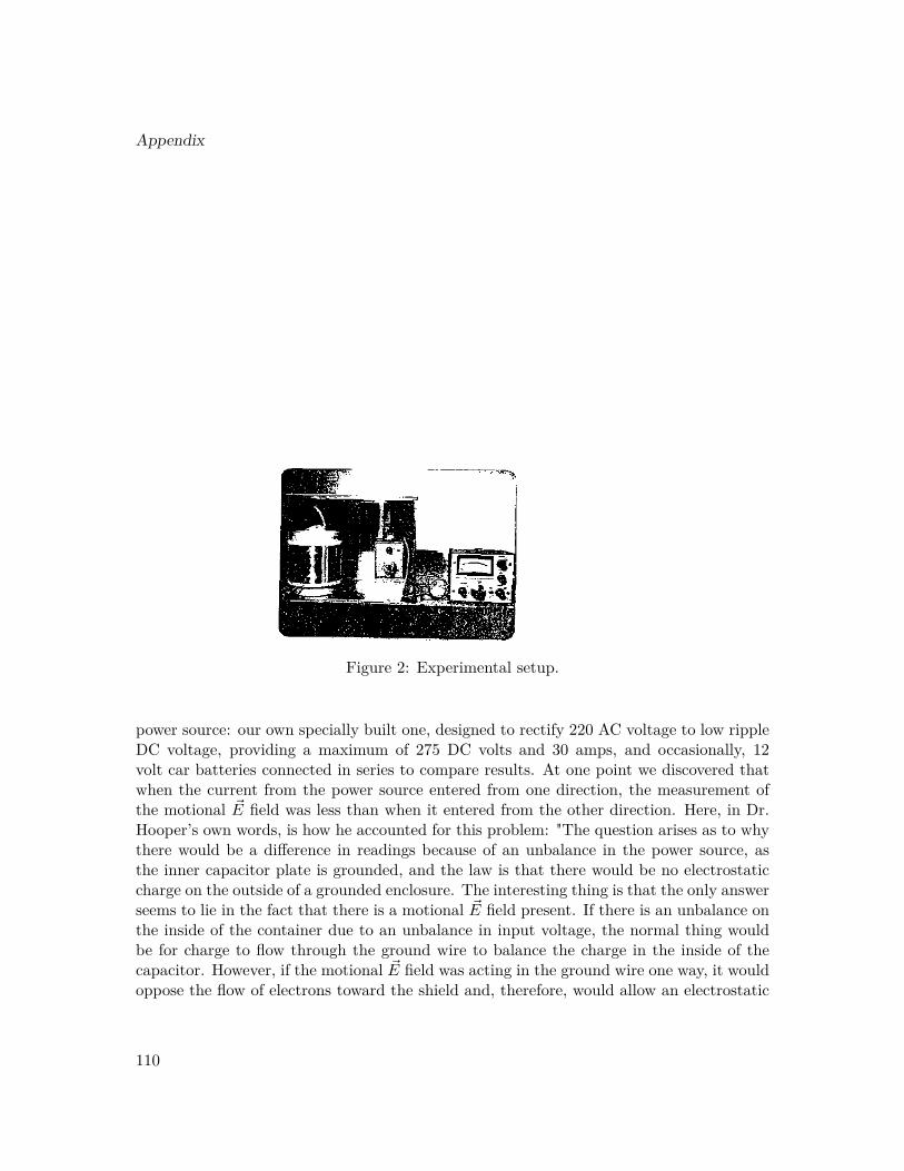
Appendix
Figure 2: Experimental setup.
power source: our own specially built one, designed to rectify 220 AC voltage to low rippleDC voltage, providing a maximum of 275 DC volts and 30 amps, and occasionally, 12volt car batteries connected in series to compare results. At one point we discovered thatwhen the current from the power source entered from one direction, the measurement ofthe motional ~E field was less than when it entered from the other direction. Here, in Dr.Hooper’s own words, is how he accounted for this problem: "The question arises as to whythere would be a difference in readings because of an unbalance in the power source, asthe inner capacitor plate is grounded, and the law is that there would be no electrostaticcharge on the outside of a grounded enclosure. The interesting thing is that the only answerseems to lie in the fact that there is a motional ~E field present. If there is an unbalance onthe inside of the container due to an unbalance in input voltage, the normal thing wouldbe for charge to flow through the ground wire to balance the charge in the inside of thecapacitor. However, if the motional ~E field was acting in the ground wire one way, it wouldoppose the flow of electrons toward the shield and, therefore, would allow an electrostatic
110

charge to remain on the inner capacitor plate and affect the readings." We had to realizethe significance of the fact that this field permeates everything.
Dr. Hooper’s explanation seemed to be confirmed by close observation of the needleon the electrometer in an experiment done immediately following this discovery. In thatexperiment, 100 V was applied to the generator; 26 amps was the resulting current. Whenthe direction of the current was one way, it was recorded that the electrometer needle firstwent negative to 11 microvolts, and then positive to 17 microvolts. When the current wasreversed, the electrometer needle only went positive to 28 microvolts. The difference be-tween the two final readings was 11 microvolts, the same as the negative deflection. Whenthe input voltage was balanced between positive and ground and between negative andground, the measurements of the motional ~E field were the same when the current wasflowing in either direction.
The above figures are not comparable to the measurements that will be referred to laterbecause different size capacitor plates were on the generator. The measurements I will beusing were taken before this discovery, but we did not redo them because we saw that theunbalance was always a negative factor, causing our readings to be less, never more. Dr.Hooper did not feel that it changed the conclusions reached, even though the exactness ofthe measurements might be questioned.
Between February 4 and July 19, 1969, when the generator was in the condition shown inFigure 2, we varied temperature, resistance, types of current, and types of power supplies.Measurements were taken by hand at 5 amp intervals, up to 30 amps. We did not have thesophisticated equipment that is available in many laboratories today. Voltage often wasnot taken because it was felt that if we took our measurements only when the generatorwas cool, the voltage would remain the same, and we wanted to move up the scale quicklybefore the generator could heat up. Also, Dr. Hooper felt that the amperage was the mostimportant factor because theory predicted that the field intensity would be directly pro-portional to the square of the amperage, because it is proportional to the virtual value ofthe magnetic field, which is proportional to the current, and to the electron drift velocity,which theory says is proportional to the current.
The following table provides some typical measurements of the potential difference mea-sured across the capacitor plates by the electrometer at room temperature. The PD readingin the third column will be the significant figure to watch from here on. This is what weconsidered to be the measurement of the intensity of the motional ~E field produced bythis generator. This measurement was never just a swing of the electrometer needle andthen back. These measurements were steady on the electrometer as long as the amperagereading was held the same, showing that the field was being produced continuously. Now,I don’t mean to say that on such a sensitive electrometer the needle was completely stable,
111

Appendix
but when the amperage was turned up the needle went up also and the instability wasalways in the area of the measurement; when we turned the amperage up more, the needlecontinued up the scale. If we had jerks of the needle in one direction or the other, we knewwe had something spurious affecting our readings, and we worked until we found out whatit was, or until it was no longer there.
The PD readings on the electrometer were always very close to a parabola, as Dr. Hooperpredicted. However, the magnitude varied from day to day. We determined that there wereat least two possible causes of this. One, there was some evidence that 8 to 10 degrees vari-ation in room temperature caused variations in the readings: the higher the temperature,the higher the readings. The reason for this may become clearer later. Two, the unbalanceof the power supply, already discussed. You will note that the fourth column of figures onthis chart shows what the predicted values of PD would be for the other amperages, basedon the experimental figure at 30 amps. The predicted parabola was always close to theactual readings.
On July 19, we went up and down the scale several times because it had been suggestedthat our readings might be due to thermoelectric effects between the two capacitor plates.This proved they were not. If our readings had been due to heat, they would not go upand down the scale with the current. These readings also show that the reading were notdue to an emf induced by changing flux. You will note, however, that after a few times upand down the scale, the generator did not begin to warm up, and the readings on the elec-trometer began to increase. We had noted this many times and had assumed that it wasdue to thermoelectric effects, and immediately stopped experimenting until the generatorcooled down. However, on June 4, we decided to see just what the effect of heating was onthe measurements.
For comparison purposes, the first set of measurements in Table 2 were taken when thegenerator was at room temperature. The second measurements were taken the same daywhen the generator was hot to the touch. When the generator was hot, the PD at all levelsincreased, and you will see the curve was no longer a parabola. However, the differencewas not totally due to thermoelectric effects, because there was a substantial jump back at25 amps. Several measurements were taken with the hot generator that day with almostidentical results. We were sorry that the voltage measurements were not taken becausethey could have given us an idea of how hot the generator was.
Because heat resistance in the generator seemed to increase the PD measurements, itwas decided to try other forms of resistance in the circuit with the generator. The firstset of numbers in Table 3 was obtained when we put a carbon pile rheostat in the line.The normal resistance of our generator was 3.7Ω. The rheostat increased the resistance inthe circuit to 5.3Ω. We discovered that these first measurements were very similar to the
112

ones where heat was the added resistance, in Table 2. We then increased the resistanceto 7.5Ω, and as you can see, there was another substantial increase in the PD readings at20 amps. Then we added photoflood at 1500 watts to the circuit, increasing its resistanceto 12.3Ω. In order not to burn them up, we only put 13 amps in the line, but if you willcompare that 13 amps with the 15 amps above, you will find a substantial increase. Formore comparison, we then returned to the rheostat and adjusted it to 12.3Ω and at 13amps we got exactly the same PD reading. Then when all resistance was removed, thereading was substantially less.
These experiments showed that our PD measurements, believed to be the measurementof the motional ~E field, increased with the addition of resistance in the circuit, and thatthe form of that resistance, whether heat, carbon pile rheostat, or photofloods, didn’t makeany difference.
Since Dr. Hooper anticipated that the best way to intensify this field would be throughthe use of superconductivity, he wanted to see the effect that cooling would have on ourgenerator. On February 28, we packed the generator, capacitors and all, with dry ice forfive hours. Then we took the first set of measurements, shown in Table 4. Unfortunately,there is no record of voltage, which would have indicated how cold the generator had got-ten. At first the results were very puzzling to us; certainly not what Dr. Hooper hadexpected. The curve was not at all parabolic. When you look at the PD at 30 amps, it isnot much different than at room temperature.
We soon discovered, however, that the results almost exactly fit the curve having a for-mula of PD = KI4, where K is the proportional constant and I is the current, whereasthe formula for a parabola is PD = KI2. Then we became excited, for it could mean thata radical change had taken place in the drift velocity of the electrons in the copper wire,somewhere between room temperature and dry ice temperatures. If this as so, it couldhelp explain the phenomenon of superconductivity. Whether it was a gradual change orwhether there was a critical temperature, we could not tell from these experiments.
That night we packed the generator in dry ice overnight, 17 hours. The readings thatwere taken the next day all fit the formula, PD = KI4. Fortunately, the first two sets ofreadings included voltage measurements from which we determined that the resistance haddropped from 3.7Ω to 2.3Ω, over one-third. You will note that sometimes we missed theproper 5 amp interval; it was because we were taking the measurements rapidly before thegenerator could heat up. I am sure that is also why we skipped the voltage measurementson that last run, and afterwards we were sorry we had.
Have you ever tried to visualize what happens to the electrons in a wire when AC voltageis applied? We decided to try to find out. On several occasions we put AC voltage into
113
Appendix
our generator from the 220 line coming into our laboratory and through our power supply.Table 5 is typical of the results. You will note that the PD readings were no longer aparabola, but almost a straight line, having its beginning at less than zero. The bottomfigures are the result of adding resistance to the circuit with AC current. Here again, youwill note that the PD increases with the addition of resistance to the circuit.
At one point we began to ask ourselves if this is the measurement of the motional ~Efield, what is happening in those wires. Fortunately, there are formulas available to giveus a clue. First of all, we determined that there was no reason to believe that the intensityof the virtual magnetic field around the generator changed with temperature when thecurrent was the same, so therefore it must be the drift velocity of the electrons that waschanging.
To get a close approximation of vd, the drift velocity of the electrons, we used the equa-tion:
PD = ~B × ~V • l (10)
where PD is the measurement of the field’s intensity across the capacitor plates, l is thedistance between the plates, ~B is the virtual magnetic field density, and ~V is the measure-ment of the drift of ~B, which is identical to the electron drift velocity, vd. From the formula,
I = Aenvd (11)
where I is the current, A is the cross-sectional area of the wire, e is the charge on theelectrons, and n is the number of conduction electrons, we see that if vd changes, n, thenumber of conduction electrons, must also change, for in this particular generator A ande are constants. Therefore, if the drift velocity changes with temperature, so must thenumber of conduction electrons. If one goes up, the other goes down.
Using equation 3, and using the calculus to integrate the line integral of the electric fieldintensity, PD, between the capacitor plates, a more exact figure for vd can be obtained.Doing it this way, suing the PD reading at 10 amps from one of the early experiments, Dr.Hooper determined the drift velocity to be 1.78 cmsec . Using the classical derivation of thedrift velocity, with Avogadro’s number, and then decreasing it by 100 as indicated by theFermi-Dirac statistics, he arrived at almost the same figure as the experimental, 1.762 cmsec .
These experiments show that the number of conduction electrons remains fairly con-stant at room temperatures and that the drift velocity increases linearly with the current.When resistance in the form of heat, carbon pile rheostat, or photo floods was added to
114

the circuit, the number of conduction electrons decreased from that of room temperatureand normal resistance while the drift velocity increased. At dry ice temperature and at lowcurrent, there were almost ten times as many conduction electrons moving, but movingvery slowly, like cars on a crowded highway. As the amperage increased, the number ofconduction electrons decreased rapidly, causing a greatly accelerated increase in the elec-tron drift velocity. When AC current was put in the generator, it appeared that 3 to 4times as many electrons were moving at low amperage as move under DC current at roomtemperature, but as with dry ice, when more electrons were moving, they were movingvery slowly. By the time the amperage increased to 20 amps the number of electrons haddecreased to almost the same number as with DC current at room temperature. From 20to 30 amps the number of electrons remained fairly constant. The electron drift velocityincreased rapidly at low amperages and continued to increase but at a decreasing rate athigher amperages.
These observations regarding electron drift velocity and number of conduction electronswould appear to be more consistent with current theory regarding gases, semiconductors,and semi-metals, than with the current theory for metals. If these findings are true, theywould seem to indicate that the conductivity of a metal is related to the number of elec-trons in motion and their velocity, both of which change with temperature and resistance.
In his book, Electromagnetism and Relativity, published in 1957, E.G. Cullwick pre-dicted, based on experimental evidence, that the magnetic field of the electron could movewith the electron drift velocity. He also said, "Measurements of the normal Hall effect inmetals are often assumed to confirm the conventional view that all the available conductionelectrons participate continuously in a conduction current." He then shows that this neednot be so.
The question is usually asked about how this motional ~E field fits into the relativitytheories. Dr. Hooper has a section in his manuscript where he says that he feels there isno conflict with the Special Theory of Relativity, only with how it is currently being inter-preted by some relativists. It does appear to conflict with the General Theory of Relativity.
In the beginning I said that Dr. Hooper began by challenging the assumption of elec-tromagnetic theory that there is only one electric field, the electrostatic, and that this ledhim to make more challenges of field theory. In formulating his theory of gravity, he hadto challenge the belief that the magnetic field, known to be present when an electron is inmotion, does not move with the electron. However, if his theory is correct, we have a solidbasis for a unified field theory, based on the motional ~E fields created when the chargesin the atoms are in motion. When he built a generator to test his theory, the resultschallenged the belief in current theory that the electron drift velocity in metals does notchange with temperature, an aspect of current theory which makes metals different from
115

Appendix
all other substances, gases, semiconductors, and semi-metals.
Dr. Hooper not only visualized that if his theory were correct that we could tap thegravitational field for energy, "atomic" energy in its most usable form; he also saw the pos-sibilities, if this motional ~E field could be intensified enough, of gravity-free areas on earth,artificial gravity in space, space vehicles, and even off-the-road vehicles on earth. He feltthat this field could be used for communication through previously impenetrable barriers,and to separate ions, such as in the desalination of water and the control of thermonuclearplasma.
Now, let’s go back to Equation 1, ~E = ~B × ~V , where ~E represents the intensity of thefield we were producing. That intensity represents the strength of the field. It must besubstantially increased before the field can be made useful. The ~V in the equation repre-sents the electron drift velocity in the material making up the generator. An increase inthe drift velocity would increase the field’s intensity. This research indicates that it can bedone at both higher and lower temperatures, and with increased resistance in the circuit.Hence, it provides a direction for more research.
To begin, most would want to duplicate the experiments here outlined. All the originalequipment is still available. That might lead to building generators like this from a varietyof materials, which would give a great deal of information about the conductivity of solids,heretofore unknown, which could indicate a pattern of activity for electrons in variousmaterials, making possible predictions about what happens to electron drift velocity atboth higher and lower temperatures, amperages, and with varying amounts of resistance.There would probably be some materials that would be best used at high temperatures,others that would be best at low temperatures, and still others that might do well at roomtemperature.
The possibilities are great that this experimentation begun in 1969 will transform theworld.
116

Table 1: Measurements taken when the generator was at room temperature.
February 4
Voltage Amperage PD microV Parabola at 30 amps35 10 7 6.752 15 15 1573 20 25 26.791 25 40 41.7110 30 60 60.0
February 11
Voltage Amperage PD microV Parabola at 30 amps– 10 10 10.0– 15 25 10.0– 20 41 40.0– 25 60 62.5– 30 90 90.0
July 19
Voltage Amperage PD microV Parabola at 30 amps– 10 15 13.9– 15 30 31.2– 20 55 55.6– 25 85 86.6– 30 125 125.0– 25 85 –– 20 50 –– 15 27 –– 10 10 –– 15 26 –– 20 50 –– 15 27 –– 10 10 –– 15 26 –– 20 55 –– 25 87 –– 30 140 –– 25 90 –
117

Appendix
Table 2: Measurements with Hot & Cold Generator.
Amps PD microV Parabola at 30 ampsCold Generator
10 11 12.815 27 28.825 50 51.025 80 79.9
Hot Generator10 13 25.015 40 56.320 75 100.025 123 156.330 220 220.0– 25 30.0
Table 3: Measurements with added resistance.
Voltage Amps PD microV Parabola 30 ampsRheostat (5.3Ω)
50 10 11 22.280 15 30 50.0107 20 70 88.9133 25 80-100 138.9160 30 200 200.0
Rheostat (7.5Ω)225 30 360 –
Photofloods (12.3Ω)160 13 100 –
Rheostat (12.3Ω)160 13 100 –
Nothing added (3.7Ω)48 13 15 –
118

Table 4: Dry ice measurements.
Voltage Amps PD microV Parabola 30 ampsDry ice (5 hours)
– 10 1.5 1.2– 15 6 5.9– 20 17 18.8– 25 45 45.8– 30 95 95.0
Dry ice (17 hours)20 10 1.5 0.532 15 2.5 2.343 20 6 7.355 25 14.5 17.868 30 37 37.021 10 – 0.633 15 2 2.845 20.5 6 8.957 25 18 21.770 30 45 45.0– 11 1 1.3– 16 5 6.0– 20 14.5 14.7– 25 40 36.0– 31 85 85.0
Table 5: AC voltage in the generator at room temperature.
Voltage Resistance Amperage PD microV– – 10 -4.5– – 15 25– – 20 70– – 25 115– – 30 150
With added resistance120 4Ω 30 20061 4Ω 15 55120 18Ω 6.7 160275 18Ω 15 220
119