Embed Size (px)
Citation preview

ca
New Fertilizer Industry Gas Cleaning Technology Achieves Lower Required Emission Levels
(Final Edit, SEPT 2008)
Air Emissions at Fertilizer Plants
All fertilizer plants produce dust and gases, such as ammonia (NH3) and acid fumes, which must be removed at very high efficiencies before venting to atmosphere. Familiar examples are granulation and prilling of nitrogenous products such as Urea which is the most widely used fertilizer in the world
(1). Phosphatic fertilizer production
produces dust and Fluorine compounds. Typical air treatment unit operations at fertilizer plants are cooling, followed possibly by a venturi scrubber, then either wet or dry ESP and finally packed bed wet scrubbing before stack discharge of the treated gas. It is common for customers to specify the maximum allowable amount of dust and trace gases that can be present in the stack emission as mg/Nm
3 of urea dust and ammonia. Consider the
examples presented in a paper last year at the 20th AFA
(2):
Project Stack Emission (mg/Nm3):
Urea – Limit / Reported Ammonia – Limit / Reported
QAFCO 4: 50 / 38 120 / 69 SAFCO 4: 30 / 24.5 140 / 79
New projects in 2008 are now requiring a maximum 20 mg/Nm
3 urea dust in the
stack emission. In addition to this move towards ever-lower allowable emission levels, there is also discussion in the trade of “clear stack” or “zero opacity” stack emission
(3).
Reduction of stack emissions is very important as dust, in the form of particulate matter, causes both unsightly haze and is also a health threat. Particulate matter of 10-μm size (PM10) can reach the alveoli of the lungs. Particulate matter of 2.5-μm size (PM2.5) is considered even more hazardous and suspended PM2.5 is typically found in mineral dusts, smoke and acid mists
(4). As seen in Figure 1, fine particulate matter does significantly impact environmental
quality.
This paper discusses wet scrubbing technology in a single cross flow vessel which can readily achieve the <20 mg/Nm
3 emission requirement. Also the implications – both practical as well as theoretical – of possible
future requirements to achieve “clear stack” emission will be explored.
Kimre’s SXFTM
Wet Scrubbing Technology
Kimre‟s SXFTM
semi-cross flow wet scrubber technology using KON-TANE® tower packing media in several
scrubbing stages followed by B-GON® mist capture media in one stage – all in a single vessel – has achieved
urea dust stack emission as low as 3 mg/Nm3 at an NPK plant in Korea
(5). In addition to being able to achieve
whatever efficiency has been demanded, SXFTM
scrubbers have a number of advantages vs. vertical – counter current flow towers. For instance, a single SXF
TM system is more effective than a traditional ESP / packed bed
wet scrubber combination.
PHASE SEPARATION TECHNOLOGY
21st Arab Fertilizer Association International Technical Conference & Exhibition
10 – 12 November 2008 Jeddah - Saudi Arabia
Figure 1-- Identical views of Frenchman’s Bay in Acadia National Park, Bar Harbor, Maine.
Left view: A clear day with visual range 199 miles (320 km) and PM2.5 of 1.4 μg/m3.
Right: A day with southwest winds that blow polluted air from New York and Boston into Eastern
Maine, visual range 30 miles (48 km) with PM2.5 of 9.6 μg/m3. Source www.hazecam.net

It has been estimated that of the 105 million tonnes of prilled and granulated urea is produced worldwide, while 3% to 5% of this amount is lost to waste as dust, fines and caking
(1). Kimre SXF
TM
wet scrubbers not only remove the urea from the air being scrubbed at extremely high efficiency, the urea so scrubbed is typically concentrated at ~40% by weight solution in the scrubber sump, and sent back to the process to be reclaimed.
KIMRE SXFTM Semi-Cross-Flow Scrubber Design Using KON-TANE® Scrubber and Tower Packing
Kimre, Inc. of Miami, Florida has been designing the uniquely configured SXF
TM Semi-Cross-Flow Scrubbers for over 35 years.
(See the sketch in Figure 2) These scrubbers are installed and are operating at high efficiencies, removing fine particulate, dust, and other contaminants such as NH3, SOX, HF, H2Cr2O7, for a wide variety of industries. Kimre
TM Technology excels in very demanding service conditions, such as in NPK fertilizer
facilities, sulfuric acid plants, steel pickling lines, RTOs, incinerators, hard chrome plating facilities and other applications too numerous to list. Refer to Table 1 for additional examples. Removal efficiency of 99.9% and higher is routinely achieved in these scrubbers.
The Kimre SXFTM
semi-cross-flow scrubber employs concurrent conditioning sprays in comparison to standard cross-flow designs. This provides the impetus for improved efficiency, by lowering the solids level of the gas stream being treated, in addition to cooling and saturating the gas flow. Then concurrent spray of the
scrubbing liquor onto the face of the KON-TANE®
stage
(or stages) follows. In some instances, a conditioning spray is also introduced on the downstream side. The scrubbing liquor flows down through the KON-TANE
®
media, crossing the horizontal gas flow, discharging into the bottom sump(s) of the scrubber.
Flow in the sump is counter-current to the gas flow, with blowdown of concentrated solution coming out of the first stage sump. Any carry-over mist is captured in the
final B-GON® stage. This proven design is shown in Figure
3.
Cross Flow – Design Advantages
Although not well documented, there are several studies of cross flow vs. traditional counter current flow scrubbers that indicate that one need not sacrifice efficiency when choosing the cross flow option. Fthenakis
(6) studied random
packings in both counter and cross flow scrubbers, finding that some commercially available packings offer equivalent mass transfer efficiency in cross and vertical flow towers, given the same other conditions. This result is supported by results reported by the University of South Queensland
(7)
paper. A common problem with random dump packing is that such packed beds tend to settle over time. That settlement usually allows gas bypass which causes an efficiency loss in such cross flow scrubbers. Note that Kimre KON-TANE
® is a
structured media, impervious to settlement, and provides a low pressure drop, typically 25 to 50 mm W.C. per stage. When mounted in a cassette, that ∆P is more than sufficient to seat and seal the media inside the scrubber vessel. This doubly assures that no gas bypass of media can occur.
Figure 2: Typical SXFTM
Scrubber Design
Initial Saturation Conditioning Sprays;
Followed by Two KON-TANE® dust
capture stages;
B-GON®
Mist Elimination Final Stage.
Table 1: Some SXFTM
Phosphate Processing
Scrubber Applications
Figure 3: SXF
TM Semi-Cross Flow Scrubber
Multiple KON-TANE® Stages provides step-wise
capture of (large to small size) particles; with final B-GON
® mist capture stage.

There are several advantages of the Kimre SXFTM
cross flow scrubber in addition to improved operational efficiencies. Among these advantages are:
Much lower height vs. vertical, counter flow scrubbers.
Easy mounting of pumps, valves, controls, etc. at ground level.
Easy access to the vessel media and accessories for normal operation and maintenance.
Much wider range of L/G ratios vs. vertical, counter-current towers, including extremely low L/G ratios.
Very easy to accommodate multiple stages; including multiple chemistries, in a single vessel.
Multiple Stages – Urea and Ammonia Scrubbing
Most Urea plants require both dust and ammonia scrubbing after the Granulator. Typically, urea dust is specified as kg/hr, with a predicted particle size distribution. Note data from a recent project at Kimre:
Air (dry) to be treated: 700,000 kg/hr Moisture Content: 25,000 kg/hr Air Temperature: 105 ºC Ammonia: 250 mg/Nm
3
Urea Dust: 6000 kg/hr 0.25% wt <0.5-μm 0.43% wt 0.5 – 1.0-μm 1.75% wt 1.0 – 3.0-μm 97.57% wt >3.0-μm
For a scrubber specified to achieve less than 20 mg dust/Nm3
the calculated required removal efficiency would be: 99.98+%. Thus a significant amount of the dust particles of <0.5-μm size must be removed for any scrubber to achieve satisfactory operation.
Three basic mechanisms come into play when collecting aerosol particles, as seen in Figure 4. A Kimre SXF
TM
scrubber using several stages of KON-TANE® media,
each stage designed to capture successively smaller Urea dust particles, can uniquely, conveniently, and economically accomplish this within a single vessel.
The basic design strategy is also seen in the design of a B-GON
® mist capture pad as noted in Figure 5.
First large particles are captured, then smaller particles, lastly the finer sized particles. A final layer of coarse material allows for a final „polish‟ as well as serves to provide structural support to the pad. Both KON-TANE
® and B-GON
® media utilize a
unique, interwoven monofilament structure, unique only to Kimre. As seen in Figure 6, this structure assures that 93% of the filaments are perpendicular to airflow direction. High particulate collection efficiency is achieved with minimal pressure drop.
Figure 5 indicates a particle size capture of 2-μm. Conventional collection of smaller particles, primarily by Brownian motion, is both difficult and inherently inefficient. Kimre™ Technology provides means to collect or treat smaller sized particles than 2-μm.
Figure 5: B-GON® mist capture pad, efficient for
2 μm and larger droplet size capture.
Figure 6: Unique Interwoven Design for
KON-TANE® and B-GON
® media
Inertial impaction is the primary mechanism of collection of relatively large particles, ~10 μm and larger.
Interception of particles becomes the important mechanism as particle size decreases. Typically, this mechanism is operative for particles of >1, to under 5-μm size.
Brownian diffusion is most important for small particle size, <1-μm, collection. It is also the most inefficient mechanism of particle capture.
Figure 4: Basic Mechanisms; Particulate Capture on Fibers
Figure 7: AEROSEP® Growth;
Submicron Particles to Micron Size.

The mass of each smaller particle significantly decreases. By definition a 2-μm water droplet has 8 times the mass of a 1-μm water droplet and 64 times the mass of a 0.5-μm droplet. Note that when an atmospheric aerosol is comprised of very small particles, such particles are extremely efficient in scattering light as seen in Figure 1. This will be discussed later in relation to proposed “clear stack” emission standards. Importantly when a significant amount of dust is present as submicron sized particles, the Kimre SXF
TM semi-cross flow scrubber is
easily adaptable to abate this problem.
AEROSEP® - Multi Stage Aerosol Separation System
The SXFTM
semi-cross flow scrubber body is easily adapted to allow for addition of an AEROSEP
® particle growth stage. The
principle of growing submicron sized particles to a 1-μm, or larger size – a size which can then be easily collected and removed, is shown schematically in Figure 7. In this example a fine aerosol of a salt, Ammonium Chloride (NH4Cl) provides a common example of a salt which typically forms a very small aerosol size (0.1 to 0.4-μm size). Small, dry particles such as this will grow in size when presented with a small amount of supersaturated water droplets. This phenomenon is known as “nucleated” condensation. When small, dry salt particles are presented with water droplets that are substantially larger in size, a micro-condensation takes place as shown in Figure 7 above. Temperatures will drop slightly as water volume increases. This will cause the salt particles to agglomerate and hence grow in size. The result is that the salt particles grow sufficiently enough large to allow their capture in the standard KON-TANE
® media.
The same mechanism occurs with acid aerosols of small droplet size, typically <1-μm. When an acid such as HCl or H2SO4 forms an aerosol, the droplets so formed are by definition composed of pure acid. The concentrated acid will have a lower vapor pressure vs. pure water. Thus even if the acid aerosol is initially very fine (Note, the CRC Handbook defines sulfuric acid aerosols as being 0.3 to 4-μm size) and as the acid droplets pass through the 100% humidity environment in the AEROSEP
® stage, the small droplets will tend to attract
water, hence grow in size.
The Kimre SXFTM
scrubber can easily be modified to include an AEROSEP
® particle growth stage as seen in Figure 8. In this
vessel, the strategy of particle removal is to first capture everything >3-μm size in Stages 1 and 2. The AEROSEP
® stage
#3 submicron sized particles are grown to 1-μm size (and larger) allowing for capture and scrubbing in Stage 4 KON-TANE
®
media. Final B-GON® mist capture is accomplished in Stage 5.
An actual AEROSEP® vessel is seen in Figure 9.
Case Study: Namhae Chemical Company NPK Plant, Yeosu, Korea
Granulator SXFTM Semi-Cross Flow Scrubber
Scrubber Performing Well, with Two-Stage Dust Removal
In 1997 the Namhae plant needed to upgrade its emissions controls to remain in compliance with updated Korean air pollution control standards. After discussions with Kimre and Kimre‟s local agent, Globetech
(8), Namhae selected a Kimre
SXFTM
Semi-Cross Flow Scrubber design to meet the requirements, which used only two stages of KON-TANE
®
followed by one stage of B-GON® media. Kimre provided the
Figure 8: AEROSEP
® Particle Growth;
3 Stage SXFTM
Scrubber & Final B-GON® Stage.
Figure 9: AEROSEP® vessel in transit to customer
Figure 10: Process Diagram
Namhae Granulator Dust Scrubber
Table 2: Granulator Scrubber Operating Data
Gas Flow: = 300,000 Am3/hr
Gas Temperature: = 39 ºC Recirculation Rates: = 437 m
3/hr (each stage)
Pressure Drop: = <70 mm H2O KON-TANE
® & B-GON
®
Dimensions: = 1830 mm by 7000 mm Superficial Gas Velocity: = 2.2 mps
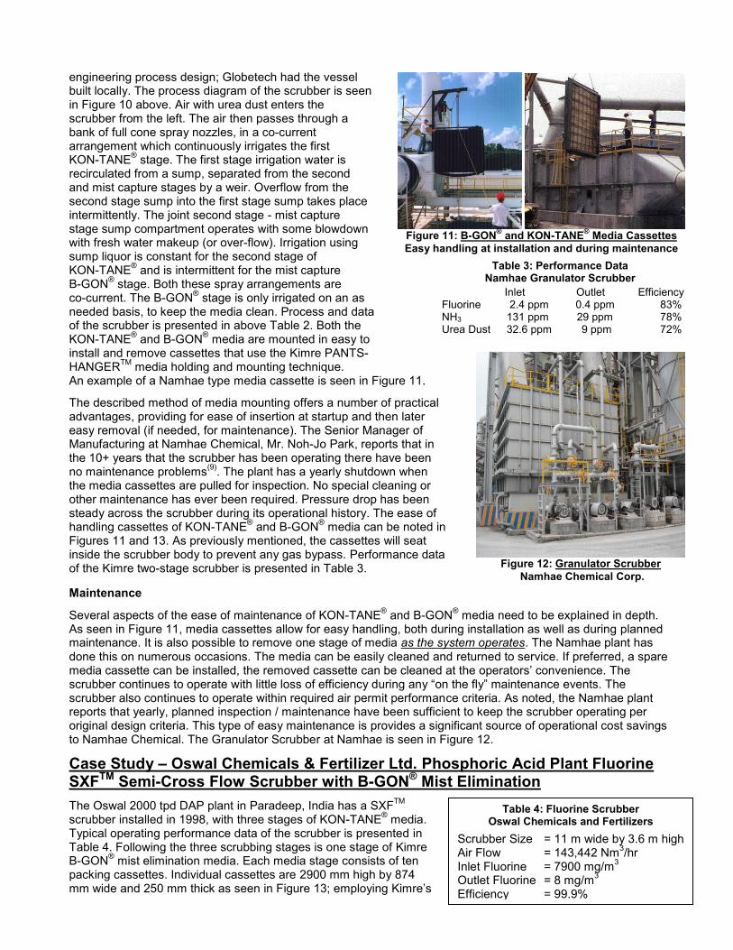
engineering process design; Globetech had the vessel built locally. The process diagram of the scrubber is seen in Figure 10 above. Air with urea dust enters the scrubber from the left. The air then passes through a bank of full cone spray nozzles, in a co-current arrangement which continuously irrigates the first KON-TANE
® stage. The first stage irrigation water is
recirculated from a sump, separated from the second and mist capture stages by a weir. Overflow from the second stage sump into the first stage sump takes place intermittently. The joint second stage - mist capture stage sump compartment operates with some blowdown with fresh water makeup (or over-flow). Irrigation using sump liquor is constant for the second stage of KON-TANE
® and is intermittent for the mist capture
B-GON® stage. Both these spray arrangements are
co-current. The B-GON® stage is only irrigated on an as
needed basis, to keep the media clean. Process and data of the scrubber is presented in above Table 2. Both the KON-TANE
® and B-GON
® media are mounted in easy to
install and remove cassettes that use the Kimre PANTS-HANGER
TM media holding and mounting technique.
An example of a Namhae type media cassette is seen in Figure 11.
The described method of media mounting offers a number of practical advantages, providing for ease of insertion at startup and then later easy removal (if needed, for maintenance). The Senior Manager of Manufacturing at Namhae Chemical, Mr. Noh-Jo Park, reports that in the 10+ years that the scrubber has been operating there have been no maintenance problems
(9). The plant has a yearly shutdown when
the media cassettes are pulled for inspection. No special cleaning or other maintenance has ever been required. Pressure drop has been steady across the scrubber during its operational history. The ease of handling cassettes of KON-TANE
® and B-GON
® media can be noted in
Figures 11 and 13. As previously mentioned, the cassettes will seat inside the scrubber body to prevent any gas bypass. Performance data of the Kimre two-stage scrubber is presented in Table 3.
Maintenance
Several aspects of the ease of maintenance of KON-TANE® and B-GON
® media need to be explained in depth.
As seen in Figure 11, media cassettes allow for easy handling, both during installation as well as during planned maintenance. It is also possible to remove one stage of media as the system operates. The Namhae plant has done this on numerous occasions. The media can be easily cleaned and returned to service. If preferred, a spare media cassette can be installed, the removed cassette can be cleaned at the operators‟ convenience. The scrubber continues to operate with little loss of efficiency during any “on the fly” maintenance events. The scrubber also continues to operate within required air permit performance criteria. As noted, the Namhae plant reports that yearly, planned inspection / maintenance have been sufficient to keep the scrubber operating per original design criteria. This type of easy maintenance is provides a significant source of operational cost savings to Namhae Chemical. The Granulator Scrubber at Namhae is seen in Figure 12.
Case Study – Oswal Chemicals & Fertilizer Ltd. Phosphoric Acid Plant Fluorine SXFTM Semi-Cross Flow Scrubber with B-GON® Mist Elimination
The Oswal 2000 tpd DAP plant in Paradeep, India has a SXFTM
scrubber installed in 1998, with three stages of KON-TANE
® media.
Typical operating performance data of the scrubber is presented in Table 4. Following the three scrubbing stages is one stage of Kimre B-GON
® mist elimination media. Each media stage consists of ten
packing cassettes. Individual cassettes are 2900 mm high by 874 mm wide and 250 mm thick as seen in Figure 13; employing Kimre‟s
Figure 11: B-GON
® and KON-TANE
® Media Cassettes
Easy handling at installation and during maintenance
Table 3: Performance Data Namhae Granulator Scrubber
Inlet Outlet Efficiency Fluorine 2.4 ppm 0.4 ppm 83% NH3 131 ppm 29 ppm 78% Urea Dust 32.6 ppm 9 ppm 72%
Figure 12: Granulator Scrubber
Namhae Chemical Corp.
Table 4: Fluorine Scrubber Oswal Chemicals and Fertilizers
Scrubber Size = 11 m wide by 3.6 m high Air Flow = 143,442 Nm
3/hr
Inlet Fluorine = 7900 mg/m3
Outlet Fluorine = 8 mg/m3
Efficiency = 99.9%

unique Pants HangerTM
media cassette mounting. The Pants HangerTM
cassettes provide for easy installation and removal as needed. Media access for normally scheduled maintenance cleaning is thus easily accomplished.
Also of interest at Oswal is the phosphoric acid plant. Fluorine is a trace element found in all phosphate rock, typically 2% to 4% of the ore processed at a phosphatic fertilizer plant
(10). Oswal has six fluorine scrubbers, each
with a 6400 mm ID. Each fluorine scrubber treats 468,000 Am
3/hr of air at 45 ºC, which contains water vapor with
4.5% fluorine. When initially designed, Kimre was asked to meet unique requirements for the mist capture needs of these scrubbers. Required performance was 99%+ capture of 10 μm and larger droplets, with minimal resistance to pluggage (caused by possible silica scale) and high liquid handling capacity; all easily accomplished with a B-GON
® pad designed with 37/97 Kimre media.
There was an additional unique requirement as the scrubbers had been designed as rubber lined vessels. Assurance had to be provided to preclude excessive pressure drop from occurring in normal operation. The concern was for excessive ΔP increases; such an increase would raise both pressure and temperature within the scrubber vessel(s) and possibly compromise the rubber lining or even support spontaneous combustion of the lining. To satisfy this design requirement, Kimre supplied the mist eliminators as seen in Figure 14 with support grids which included pressure relief doors. The doors were placed strategically across the pad‟s cross-section. The doors were designed of a specific mass to allow opening only when the pressure drop across the pad exceeded 50 mm WC. In such an event, the open doors allowing hot gas bypass, avoiding possible catastrophic temperature increases within the scrubber vessel. The entire construction of each B-GON
® pad, support
frame, and doors was of high temperature polypropylene (HTPP).
Clear Stack - Implications
Certainly improved emissions are possible. One Kimre SXF®
scrubber noted previously and as indicated in Table 3, reduced dust emissions to less than 10 ppmv while employing only two stages of media. Even lower emission levels are certainly possible, that just requires one or more additional stages added to the scrubber. A model of a SXF
TM
scrubber with five KON-TAN® stages is shown in Figure 15.
Of course additional stages, some possibly containing finer grades of KON-TANE
®, will yield higher capital costs due to
increased vessel size. Additional stages may increase power costs due to inevitably higher-pressure drop, and, water usage may also increase. Operational expense of the scrubber will be modestly higher compared to past practice.
Society needs additional fertilizer capacity for world food production to keep pace with growing population. People also wish to live healthy lives in a clean environment. However, at some point, it may be realized that industry is doing all that is practical to clean plant emissions. As seen in Figure 16 (below), certainly low-level smog caused by fine particulate matter is a serious problem. In addition to human activity, air quality problems are also due to natural factors such as volcanoes
(11), dust storms, also other seasonal factors affecting atmospheric opacity
(12,13).
The term “clear stack” is also not well defined. “Opacity” as defined by the US EPA indicates the amount of light obscured by particulate pollution in the air – a clear glass window has zero opacity and a brick wall is 100% opaque
(14). However, visibility is also dependent upon individual interpretation
(15). So if the move towards “clear
stack emissions” is driven, in part, by a desire to prevent public complaints it is likely not to succeed. Someone somewhere, will still perceive a problem in local atmospheric quality – and in conjunction with a nearby fertilizer
Figure 15: SXFTM
Cross Flow Scrubber Model.
5 KON-TANE® Stages and Final B-GON
® Stage
Figure 13: Oswal KON-TANE
® Media
Utilizing KIMRETM
Cassette mounting
Figure 14: B-GON® Fluorine Scrubber

plant location, the next “logical” conclusion (or perception) may be that the local plant must be the source of the problem.
Although small droplets carry very little mass, when present the small aerosol particles efficiently diffract sunlight. The smallest sized droplets normally comprise an equally small percentage of the overall distribution of an acid gas plume – the smallest sized droplets disproportionately contribute to the opacity of the plume exiting the scrubber stack. For example, a typical HCl acid gas scrubber abating fumes from a metal pickling line is typically designed to achieve 99+% overall scrubber removal efficiency for 2-μm (and larger) acid droplets. This particulate efficiency minimizes the opacity of the scrubber plume rather than promise a “clear stack” – a promise which is never given by an experienced scrubber supplier for such an application. The fertilizer industry needs to consider the removal efficiency for scrubber performance, when challenged with “clear stack” emissions as a practical performance goal. Author, Presenter
George C. (Chris) Pedersen, P.E., Chief Technical Officer, Kimre Inc., [email protected]
Coauthor, Co-presenter
James E. Eldridge, Senior Applications Engineer, [email protected]
Coauthors
Frederick Mueller (Editor) Manager, Sales & Marketing [email protected] Dr. Diana Marmorstein, Applications Engineer, [email protected] Jose Valesquez, Applications Engineer, [email protected] Marilia Da Silva, Application Engineer, [email protected] Nadav Ben-Chanoch, Applications Engineer, [email protected]
References
(1) Avdhesh, M., Urea Quality Improvement, 19th AFA 2006.
(2) Potthof, M., Mega Urea Granulation Plants Up and Running – Potentials for Future Development, 20th AFA,
2007. (3) Recent Experiences at Kimre, Inc., 2008. (4) Kjellstrom, T., Lodh, M., McMichael, T., Ranmuthugala, R., Shrestha, R. and Kingsland, S., Air and Water Pollution: Burden and Strategies for Control, World Bank Group, 2008. (5) Shin, K., Private Communication, Globetech Inc., Gyunggi Do, Korea, [email protected] (6) Fthenakis, V.M., Cross-Flow versus Counter Flow Packed Bed Scrubbers: A Mathematical Analysis, AIChE Spring National Meeting, New Orleans, LA, 1996. (7) Jiuan, Y.L., Evaluation of Wet Scrubber Systems, University of Southern Queensland, Brisbane, Australia, www.usq.edu.au , Oct. 2005. (8) Shin, K., ibid. (9) Shin, K., ibid. (10) Environmental, Health and Safety Guidelines: Phosphate Fertilizer Plants Manufacturing, World Bank Group, 2007. (11) McAvoy, A., VOG Cast Haze over Hawaii, The Associated Press, May 5, 2008. (12) Chamberlain, R.A. and Martin, C.L., Atmospheric Opacity from a Submillimeter FTS at the Geographic South Pole, Caltech, 2003. (13) Matsuo, H., Sakamoto, A. and Matshushita, S., FTS Measurements of Submillimeter Wave Atmospheric Opacity at Pampa la Bola Chile, Astronomical Society of Japan 50, 359 – 366, 1998. (14) http://www.epa.gov/OCEPAtems/oterms.html (15) Visibility / Haze Metric, http://vista.circa.colostate.edu/improve/Tools/Vis_Haze_Metrics.htm
Figure 16. Low-level Smog caused by airborne fine particulate matter covers much of
China (as seen in 2002 NASA photo).

Kimre, Inc. Product Line
B-GON® Mist Eliminators
Typically used in separating soluble and condensable mists and particulates from gas streams in a scrubber or absorber. Using Kimre media, droplets of sizes ranging from just under 1 micron in diameter to over 100 microns in diameter can be efficiently removed. B-GON
® Mist Eliminators are used in a host of industries, including fertilizer plants, acid production, metal
reefing, chemical industries, machining operations and polymer processing facilities, and collection of oil mist and lubricants. Typically, the face velocities of the gas streams range from 400 to 700 fpm (2.0 to 3.6 mps).
KON-TANE® Tower Packing
Tower Packing consists of pads of structured packing, made of the same materials as the B-GON® Mist Eliminators, and
LIQUI-NOMIX® Separators. KON-TANE
®, in the Kimre SXF
TM Semi-Cross-Flow scrubber, provides high contact areas and
typically achieves over three (3) plus mass transfer units per 7” (~180 mm) thick stage. It is robust and can be designed for easy removal and cleaning when used in dirty service.
SXFTM
Semi-Cross Flow Scrubber
As discussed in this paper, the SXFTM
Semi-Cross-Flow Scrubber, horizontal design, and, uniquely adaptable to multiple types and multiple stages of scrubbing and particulate abatement. The SXF™ provides for very simple, uncomplicated system maintenance (on-line cleaning in situ) with overall low operational pressure drop, at high operating efficiencies.
AEROSEP® Multi-Stage Aerosol Separation
As discussed in this paper this is a multi stage separation system. The AEROSEP® system can be used to remove very fine,
submicron hygroscopic aerosols in a gas stream. In addition, AEROSEP® systems can very efficiently treat fine salt fumes,
acid aerosols and incinerator emissions.
DRIFTOR® (Cooling Tower) Drift Eliminator
Drift Eliminators are typically made of just one or a few layers of the coarser structured mesh pads. DRIFTOR® provides high removal efficiency and low pressure drops for the large droplets carried through cooling towers. Unlike chevron-style drift eliminators, Kimre‟s DRIFTOR
® Drift Eliminators are flexible and easily configured to fit into any cooling tower configuration.
LIQUI-NOMIX® Liquid / Liquid Separation Media
Polishing filters in gravity settlers for separating oil droplets from water streams (or any two immiscible liquids of different densities). Using LIQUI-NOMIX
® it is possible to remove contaminant oil droplets down to a contaminant level less than 10
ppmv. LIQUI-NOMIX® can be used for liquid streams in which the dispersed liquids can be separated over time with gravity.
Sunset over Miami from Miami Beach Florida, USA
KIMRE, INC. P.O. Box 571240 Miami FL 33257-1240 USA
Tel: (305) 233-4249 Fax: (305) 233-8687 Email: [email protected]
Internet: http://www.kimre.com
KIMRE EUROPE, NV Koolmijnlaan 201 B-3582 Beringen Belgium Tel: +32 (0) 11 450- 758 +32 (0) 11 450 759
Email: [email protected]