Embed Size (px)
Citation preview

AUTODESK® INFERNO® 2007 Extension 1
AUTODESK® FLAME® 2007 Extension 1
AUTODESK® FLINT® 2007 Extension 1A Discreet® Systems product
Autodesk Inferno, Autodesk Flame, and Autodesk Flint 2007 Extension 1 New FeaturesGuide
New Features Guide

© 2007 Autodesk Canada Co./Autodesk, Inc. All Rights Reserved.
This publication, or parts thereof, may not be reproduced in any form, by any method, for any purpose.
AUTODESK CANADA CO./AUTODESK, INC., MAKES NO WARRANTY, EITHER EXPRESS OR IMPLIED, INCLUDING BUT NOTLIMITED TO ANY IMPLIED WARRANTIES OF MERCHANTABILITY OR FITNESS FOR A PARTICULAR PURPOSE REGARDINGTHESE MATERIALS, AND MAKES SUCH MATERIALS AVAILABLE SOLELY ON AN "AS-IS" BASIS. IN NO EVENT SHALL AUTODESKCANADA CO./AUTODESK, INC., BE LIABLE TO ANYONE FOR SPECIAL, COLLATERAL, INCIDENTAL, OR CONSEQUENTIALDAMAGES IN CONNECTION WITH OR ARISING OUT OF ACQUISITION OR USE OF THESE MATERIALS. THE SOLE ANDEXCLUSIVE LIABILITY TO AUTODESK CANADA CO./AUTODESK, INC., REGARDLESS OF THE FORM OF ACTION, SHALL NOTEXCEED THE PURCHASE PRICE, IF ANY, OF THE MATERIALS DESCRIBED HEREIN.
Autodesk Canada Co./Autodesk, Inc., reserves the right to revise and improve its products as it sees fit. This publication describes the state of thisproduct at the time of its publication, and may not reflect the product at all times in the future.
The following are registered trademarks or trademarks of Autodesk, Inc., in the USA and other countries: 3DEC (design/logo), 3December,3December.com, 3ds Max, ActiveShapes, Actrix, ADI, Alias, Alias (swirl design/logo), AliasStudio, Alias|Wavefront (design/logo), ATC, AUGI,AutoCAD, AutoCAD Learning Assistance, AutoCAD LT, AutoCAD Simulator, AutoCAD SQL Extension, AutoCAD SQL Interface, Autodesk,Autodesk Envision, Autodesk Insight, Autodesk Intent, Autodesk Inventor, Autodesk Map, Autodesk MapGuide, Autodesk Streamline, AutoLISP,AutoSnap, AutoSketch, AutoTrack, Backdraft, Built with ObjectARX (logo), Burn, Buzzsaw, CAiCE, Can You Imagine, Character Studio,Cinestream, Civil 3D, Cleaner, Cleaner Central, ClearScale, Colour Warper, Combustion, Communication Specification, Constructware, ContentExplorer, Create>what’s>Next> (design/logo), Dancing Baby (image), DesignCenter, Design Doctor, Designer's Toolkit, DesignKids, DesignProf,DesignServer, DesignStudio, Design|Studio (design/logo), Design Your World, Design Your World (design/logo), DWF, DWG, DWG (logo),DWG TrueConvert, DWG TrueView, DXF, EditDV, Education by Design, Extending the Design Team, FBX, Filmbox, FMDesktop, GDX Driver,Gmax, Heads-up Design, Heidi, HOOPS, HumanIK, i-drop, iMOUT, Incinerator, IntroDV, Kaydara, Kaydara (design/logo), LocationLogic,Lustre, Maya, Mechanical Desktop, MotionBuilder, ObjectARX, ObjectDBX, Open Reality, PolarSnap, PortfolioWall, Powered with AutodeskTechnology, Productstream, ProjectPoint, Reactor, RealDWG, Real-time Roto, Render Queue, Revit, Showcase, SketchBook, StudioTools,Topobase, Toxik, Visual, Visual Bridge, Visual Construction, Visual Drainage, Visual Hydro, Visual Landscape, Visual Roads, Visual Survey, VisualSyllabus, Visual Toolbox, Visual Tugboat, Visual LISP, Voice Reality, Volo, and Wiretap.
The following are registered trademarks or trademarks of Autodesk Canada Co. in the USA and/or Canada and other countries: Backburner,Discreet, Fire, Flame, Flint, Frost, Inferno, Multi-Master Editing, River, Smoke, Sparks, Stone, Wire.
All other brand names, product names, or trademarks belong to their respective holders.
Third-Party Software Credits and Attributions
Portions of this software are copyright the FreeType Project (www.freetype.org). All rights reserved.
Apache License 2.0 – Perpetual, worldwide, non-exclusive, no-charge, royalty-free, irrevocable: (i) copyright license to reproduce, preparederivative works of, publicly perform, publicly display, sublicense and distribute the Work and any Derivative Works in source or object form; (ii)patent license to make, have made, use, offer to sell, sell import and otherwise transfer the Work.
Powered by Automatic Duck. © 2006 Automatic Duck, Inc. All rights reserved.
Portions copyright 1991-2006 Compuware Corporation.
Portions of this product Copyright 2006 Glyph & Cog, LLC.
DIRAC Time Stretch/Pitch Shift technology licensed from The DSP Dimension, http://www.dspdimension.com Developed and (c) 2005 StephanM. Bernsee.
This software uses the ffmpeg library, licensed under the LGPL license. See the file THIRD_PARTIES_LICENSES.txt (distributed with thissoftware) for more details about ffmpeg licensing terms or visit: http://ffmpeg.org/
This software uses the libquicktime library, licensed under the LGPL license. See the file THIRD_PARTIES_LICENSES.txt (distributed with thissoftware) for more details about libquicktime licensing terms or visit: http://libquicktime.sourceforge.net/
GOVERNMENT USE
Use, duplication, or disclosure by the U.S. Government is subject to restrictions as set forth in FAR 12.212 (Commercial Computer Software-Restricted Rights) and DFAR 227.7202 (Rights in Technical Data and Computer Software), as applicable.
Published By: Autodesk Canada Co./Autodesk, Inc. 111 Mclnnis Parkway San Rafael, CA 94903, USA
Title: Autodesk Inferno, Autodesk Flame, and Autodesk Flint 2007 Extension 1 New Features GuideDocument Version: 2
Date: March 23, 2007

contents
iii
Contents
1 Introduction 1Summary . . . . . . . . . . . . . . . . . . . . . . . . . . . . . . . . . . . . . . . . . . . . . . . . . . . . . . . . . . . . . . . 1Welcome to Autodesk Effects 2007 Extension 1 . . . . . . . . . . . . . . . . . . . . . . . . . . . . . . 1Compatibility. . . . . . . . . . . . . . . . . . . . . . . . . . . . . . . . . . . . . . . . . . . . . . . . . . . . . . . . . . . . 1Using This Guide . . . . . . . . . . . . . . . . . . . . . . . . . . . . . . . . . . . . . . . . . . . . . . . . . . . . . . . . 2Notation Conventions . . . . . . . . . . . . . . . . . . . . . . . . . . . . . . . . . . . . . . . . . . . . . . . . . . . . 2Related Documentation. . . . . . . . . . . . . . . . . . . . . . . . . . . . . . . . . . . . . . . . . . . . . . . . . . . 2Contacting Customer Support . . . . . . . . . . . . . . . . . . . . . . . . . . . . . . . . . . . . . . . . . . . . . 3
2 What’s New 5Summary . . . . . . . . . . . . . . . . . . . . . . . . . . . . . . . . . . . . . . . . . . . . . . . . . . . . . . . . . . . . . . . 5Action . . . . . . . . . . . . . . . . . . . . . . . . . . . . . . . . . . . . . . . . . . . . . . . . . . . . . . . . . . . . . . . . . . 5Adding Notes to Clips . . . . . . . . . . . . . . . . . . . . . . . . . . . . . . . . . . . . . . . . . . . . . . . . . . . . 6Batch . . . . . . . . . . . . . . . . . . . . . . . . . . . . . . . . . . . . . . . . . . . . . . . . . . . . . . . . . . . . . . . . . . . 8Burn Support in Modules . . . . . . . . . . . . . . . . . . . . . . . . . . . . . . . . . . . . . . . . . . . . . . . . . 9Clip Libraries: Transferring Clips Using Autodesk Wire . . . . . . . . . . . . . . . . . . . . . . . 11Clip Library Tools: Unlinking Media from Clips . . . . . . . . . . . . . . . . . . . . . . . . . . . . . 12Generating Proxies in the Background . . . . . . . . . . . . . . . . . . . . . . . . . . . . . . . . . . . . . . 15Hot Keys . . . . . . . . . . . . . . . . . . . . . . . . . . . . . . . . . . . . . . . . . . . . . . . . . . . . . . . . . . . . . . . 15Importing DPX Sequences for Data Conform . . . . . . . . . . . . . . . . . . . . . . . . . . . . . . . . 16Layer-Based Paint (Linux only) . . . . . . . . . . . . . . . . . . . . . . . . . . . . . . . . . . . . . . . . . . . . 20Lustre Color Management. . . . . . . . . . . . . . . . . . . . . . . . . . . . . . . . . . . . . . . . . . . . . . . . . 21QuickTime Support for Linux . . . . . . . . . . . . . . . . . . . . . . . . . . . . . . . . . . . . . . . . . . . . . 21Searching for Mixed Resolution Sources . . . . . . . . . . . . . . . . . . . . . . . . . . . . . . . . . . . . 24Setting Desktop Preferences . . . . . . . . . . . . . . . . . . . . . . . . . . . . . . . . . . . . . . . . . . . . . . . 26Batch Timeline Editing . . . . . . . . . . . . . . . . . . . . . . . . . . . . . . . . . . . . . . . . . . . . . . . . . . . 27

tentsCon
iv
Zooming in Viewports . . . . . . . . . . . . . . . . . . . . . . . . . . . . . . . . . . . . . . . . . . . . . . . . . . . . 30
3 3D Camera Tracking (Inferno and Flame) 33Summary . . . . . . . . . . . . . . . . . . . . . . . . . . . . . . . . . . . . . . . . . . . . . . . . . . . . . . . . . . . . . . . 33About 3D Camera Tracking . . . . . . . . . . . . . . . . . . . . . . . . . . . . . . . . . . . . . . . . . . . . . . . 33Accessing the 3D Tracker . . . . . . . . . . . . . . . . . . . . . . . . . . . . . . . . . . . . . . . . . . . . . . . . . 33Preparing to Track . . . . . . . . . . . . . . . . . . . . . . . . . . . . . . . . . . . . . . . . . . . . . . . . . . . . . . . 34Auto 3D Tracking . . . . . . . . . . . . . . . . . . . . . . . . . . . . . . . . . . . . . . . . . . . . . . . . . . . . . . . . 35Manual 3D Tracking. . . . . . . . . . . . . . . . . . . . . . . . . . . . . . . . . . . . . . . . . . . . . . . . . . . . . . 41
4 Lens Distortion 59Summary . . . . . . . . . . . . . . . . . . . . . . . . . . . . . . . . . . . . . . . . . . . . . . . . . . . . . . . . . . . . . . . 59About Lens Distortion . . . . . . . . . . . . . . . . . . . . . . . . . . . . . . . . . . . . . . . . . . . . . . . . . . . . 59Accessing the Lens Distort Batch Node. . . . . . . . . . . . . . . . . . . . . . . . . . . . . . . . . . . . . . 59Performing a Perspective Rectification (or Distortion) . . . . . . . . . . . . . . . . . . . . . . . . 61Rectifying an Image with Spline Analysis . . . . . . . . . . . . . . . . . . . . . . . . . . . . . . . . . . . . 63

1
Introduction
SummaryWelcome to Autodesk Effects 2007 Extension 1 . . . . . . . . . . . . . . . . . . . . . . . . . . . . . 1
Compatibility . . . . . . . . . . . . . . . . . . . . . . . . . . . . . . . . . . . . . . . . . . . . . . . . . . . . . . . . . . . . . 1
Using This Guide . . . . . . . . . . . . . . . . . . . . . . . . . . . . . . . . . . . . . . . . . . . . . . . . . . . . . . . . . . 2
Notation Conventions . . . . . . . . . . . . . . . . . . . . . . . . . . . . . . . . . . . . . . . . . . . . . . . . . . . . 2
Related Documentation . . . . . . . . . . . . . . . . . . . . . . . . . . . . . . . . . . . . . . . . . . . . . . . . . . . 2
Contacting Customer Support . . . . . . . . . . . . . . . . . . . . . . . . . . . . . . . . . . . . . . . . . . . . . 3
Welcome to Autodesk Effects 2007 Extension 1Autodesk® Effects 2007 Extension 1 includes innovative tools that will enhance your creativity and productivity with Autodesk Inferno® 2007, Autodesk Flame® 2007, and Autodesk Flint® 2007.
Extension features are available only to subscription customers. For more information on the Subscription Program, see the Media and Entertainment Subscription Program Web site.
CompatibilityAutodesk makes every effort to ensure that media and resources are completely forward and backward compatible between the initial release of your Autodesk Effects 2007 product and the Extension 1 release.
This means that you can open Extension 1 projects, clip libraries, archives, users, and setups on a system with the main release of the Effects 2007 product. In addition, you can open Effects 2007 projects, clip libraries, users, and setups on a system with Extension 1.
If you have a version of an Autodesk Effects application that pre-dates the 2007 release, there are other compatibility issues to consider. See the “Compatibility” chapter of your application’s User’s Guide.

Introduction1
2
Using This GuideThis guide describes the new features included in the release of Inferno 2007, Flame 2007, and Flint 2007 Extension 1. An overview of each feature can be found in the “What’s New” chapter. More detailed information on the feature (if available) can be found in its respective chapter.
Notation ConventionsA number of style conventions are used throughout this guide. These conventions and examples of their use are shown as follows.
Related DocumentationThe following tables list the documentation associated with the current release. For details on each of these documents, as well as for help obtaining them, refer to the Autodesk Inferno, Flint and Flame 2007 SP3 and Extension 1 Release Notes.
Convention Example
Text that you enter in a command line or shell appears in Courier bold. You must press the Enter key after each command.
install rpm -qa
Variable names appear in Courier, enclosed in angle brackets.
<filename>
Feedback from the command line or shell appears in Courier.
limit coredumpsize
Directory names, filenames, URLs, and command line utilities appear in italics.
/usr/discreet
User and Reference Guides Description
Autodesk Inferno, Autodesk Flame, Autodesk Flint 2007 Extension 1 New Features Guide
Detailed instructions on using the new features available in Extension 1 of the Effects products
Autodesk Fire, Autodesk Smoke, and Autodesk Backdraft Conform 2007 Extension 1 New Features Guide
Detailed instructions on using the new features available in Extension 1 of the Editing products
User’s Guide Detailed instructions on using the software
What’s New A complete list of the new features for the main 2007 release
Online Help All of the information in the User’s Guide along with powerful search functionality
Hot Keys Reference Guide A complete list of hot keys for commonly used functions
Hot Keys Card A list of the most frequently used hot keys

Contacting Customer Support
3
yww
Consult the Autodesk Web site at www.autodesk.com/discreet-documentation for the latest version of all documents.
Contacting Customer SupportYou can contact Autodesk Media and Entertainment Customer Support at www.autodesk.com/support or in one of the following ways.
Release Notes A complete list of documentation and information on late-breaking features
Fixed and Known Bugs A complete list of fixed and known bugs for this release
Installation and Configuration Guides Description
Hardware Setup Guide(for your workstation)
Information on how to set up your workstation’s video I/O components and other peripherals
Installation and Configuration Guide(for your operating system)
Information on how to install and configure the Linux® or IRIX® operating system on your workstation should you require to do so
Stone and Wire Filesystem and Networking Guide(for this release)
Procedures for configuring your Autodesk Stone® filesystem, Autodesk Wire® networking, and Autodesk Wiretap™ services
Stone Direct Configuration Guide (for this release)
Detailed connectivity diagrams and configuration procedures for your Stone storage arrays
Software Installation Guide(for Linux or IRIX workstations)
Information about installing and licensing yourAutodesk Editing or Effects software and installing and configuring Autodesk Cleaner® XL
Configuration File Reference Guide(for Linux or IRIX workstations)
Information on how to modify the initialization and project configuration files associated with your Autodesk application
Other Product Reference Guides Description
Autodesk Cleaner XL User's Guide Information on how to use Cleaner XL
Autodesk Cleaner XL Troubleshooting Guide
Troubleshooting information for Cleaner XL
Autodesk Burn Installation and User’s Guide
Information on how to install, set up, and use Autodesk Burn™
Autodesk Backburner Installation and User’s Guide
Information on how to install, set up, and use Autodesk Backburner™
Autodesk Wiretap Web Installation and User’s Guide
Information on how to install, set up, and use Autodesk Wiretap™ Web
User and Reference Guides Description

Introduction1
4
Customer support is also available through your Autodesk reseller. To find a reseller near you, consult the reseller look-up database on the Autodesk Web site at www.autodesk.com/resellers.
Location: Contact Information:
Within the Americas: Hotline (North America): 1-800-925-6442 Direct dial: 415-507-5256 (Country code = 1)8 AM to 8 PM EST Monday to Friday, excluding [email protected]
Within Europe, Middle-East and Africa:
Hotline (from London, UK): +44-207-851-8080 9 AM to 5:30 PM (local time)Monday to Friday, excluding [email protected]
Within Asia Pacific:(Excluding India, China, Australia, New Zealand and Japan)
Hotline (from Singapore): +65-6555-0399 9 AM to 6 PM (local time)Monday to Friday, excluding [email protected]
Within India: Hotline (from Mumbai): +91-22-6695-2244 9:30 AM to 6:30 PM (local time) Monday to Friday, excluding [email protected]
Within Japan: Hotline (from Tokyo): 0120-107-290Direct dial: +81-3-6221-181010 AM to 6 PM (local time) Monday to Friday, excluding [email protected]
Within China: Direct dial: +86-10-6505-68489 AM to 6 PM (local time) Monday to Friday, excluding [email protected]
Within Australia and New Zealand: Hotline (within Australia to Melbourne): +1-300.36.8355Hotline (within New Zealand to Melbourne): 0800 555 301Direct dial: +61.3.9876.89358 AM to 6 PM AESTMonday to Friday, excluding certain [email protected]

5
What’s New
SummaryAction . . . . . . . . . . . . . . . . . . . . . . . . . . . . . . . . . . . . . . . . . . . . . . . . . . . . . . . . . . . . . . . . . . . . 5
Adding Notes to Clips . . . . . . . . . . . . . . . . . . . . . . . . . . . . . . . . . . . . . . . . . . . . . . . . . . . . . 6
Batch . . . . . . . . . . . . . . . . . . . . . . . . . . . . . . . . . . . . . . . . . . . . . . . . . . . . . . . . . . . . . . . . . . . . . 8
Burn Support in Modules . . . . . . . . . . . . . . . . . . . . . . . . . . . . . . . . . . . . . . . . . . . . . . . . . . 9
Clip Libraries: Transferring Clips Using Autodesk Wire . . . . . . . . . . . . . . . . . . . . . . 11
Clip Library Tools: Unlinking Media from Clips . . . . . . . . . . . . . . . . . . . . . . . . . . . . . 12
Generating Proxies in the Background . . . . . . . . . . . . . . . . . . . . . . . . . . . . . . . . . . . . 15
Hot Keys . . . . . . . . . . . . . . . . . . . . . . . . . . . . . . . . . . . . . . . . . . . . . . . . . . . . . . . . . . . . . . . . . 15
Importing DPX Sequences for Data Conform . . . . . . . . . . . . . . . . . . . . . . . . . . . . . . 16
Layer-Based Paint (Linux only) . . . . . . . . . . . . . . . . . . . . . . . . . . . . . . . . . . . . . . . . . . . . 20
Lustre Color Management . . . . . . . . . . . . . . . . . . . . . . . . . . . . . . . . . . . . . . . . . . . . . . . . 21
QuickTime Support for Linux . . . . . . . . . . . . . . . . . . . . . . . . . . . . . . . . . . . . . . . . . . . . . 21
Searching for Mixed Resolution Sources . . . . . . . . . . . . . . . . . . . . . . . . . . . . . . . . . . . 24
Setting Desktop Preferences . . . . . . . . . . . . . . . . . . . . . . . . . . . . . . . . . . . . . . . . . . . . . . 26
Batch Timeline Editing . . . . . . . . . . . . . . . . . . . . . . . . . . . . . . . . . . . . . . . . . . . . . . . . . . . 27
Zooming in Viewports . . . . . . . . . . . . . . . . . . . . . . . . . . . . . . . . . . . . . . . . . . . . . . . . . . . . 30
ActionThe following features are now supported in the Action module.
New 3D Tracker (Inferno and Flame only)The 3D tracker has been redesigned to offer a faster and more effective analysis to extract camera motion information from a live action shot. See “3D Camera Tracking (Inferno and Flame)” on page 33.
What’s New2
6
Muting Action LayersYou can now mute Keyer and Colour Corrector layers in the Action Layers menu. Muting a layer can be helpful to see what your Action setup looks like without the Keyer or Colour Corrector settings, but not lose any of the settings of the muted layer.
To mute a layer, press ALT and click the K (or MK) or CC layer. The check mark in the field turns black to signify the layer is muted. To unmute the layer, press ALT and click the field again.
Adding Notes to ClipsYou can add notes to clips on the desktop using the built-in notepad, which is a simple text editor. Each entry is annotated with the creation date and time of the note and the user who entered it, so you can use the clip notepad as an informal discussion area for clips in progress.
Notes are saved as part of the clip’s metadata so the information is preserved if you transfer the clip to another workstation using Wire. When you copy a clip on the desktop that contains notes, the notes are copied too. When you archive a clip, its notes are saved with the archived clip.
To add notes to a clip’s notepad:
1. Put the cursor over a clip on the desktop and press V.
2. Enter your notes in the notepad that appears.
a) Muted layer
a

Adding Notes to Clips
7
yww
3. Click anywhere outside the notepad to close it.
An icon with the letter “N” appears on the clip, indicating that it has a note.
To edit a clip’s notepad:
1. Put the cursor over a clip on the desktop that has a note and press V.
The notepad appears with an annotation that tracks the creation date and time and the user who added each note.
2. Place the cursor after the last line and then enter your notes.
HINT: When you enter a note, the annotation is always added as the last line. To ensure an
easily trackable sequence of notes, add new notes at the end.
3. Click anywhere outside the notepad to close it.
To delete a clip’s notepad:
1. Put the cursor over a clip on the desktop that has a note and press V.
2. Select all text in the notepad and then delete it.
a) Note icon
a) Annotation
a
a

What’s New2
8
3. Click anywhere outside the notepad to close it.
The “N” icon disappears, indicating the note has been deleted.
To resize a notepad:
Click the lower-right corner of the notepad and drag.
A red outline of the notepad appears as you drag.
BatchThe following features are now supported in Batch.
Lens Distort Batch NodeThe new Lens Distort Batch node allows you to simulate or rectify lens distortion in your clips. See “Lens Distortion” on page 59.
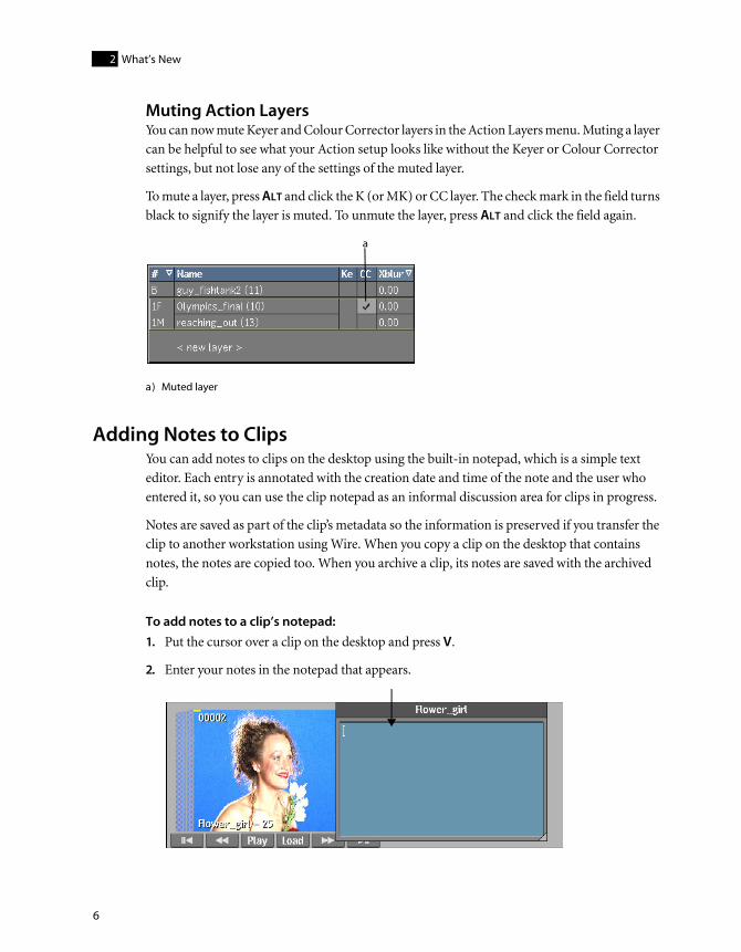
Activating or Deactivating Processing of All Output and Export NodesThere is a new Enable All/Disable All button in the Queue Manager in Batch. The Enable All/Disable All button activates or deactivates processing on all Output and Export nodes in the process tree.
To open the Queue Manager, click an Output or Export node in Batch.
For more information on Batch, see the “Batch Processing” chapter in the User’s Guide.
a) Enable All/Disable All button
a
Burn Support in Modules
9
yww
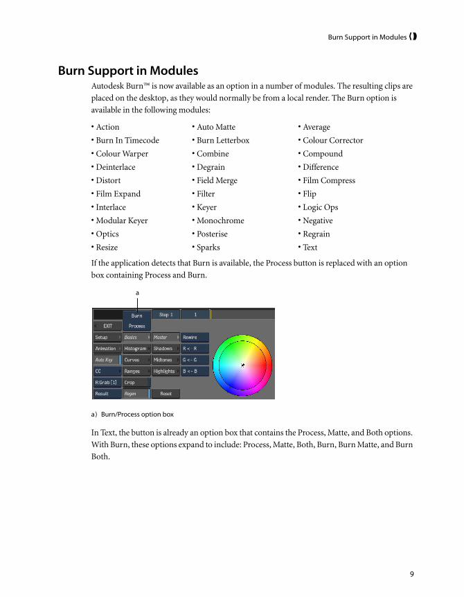
Burn Support in ModulesAutodesk Burn™ is now available as an option in a number of modules. The resulting clips are placed on the desktop, as they would normally be from a local render. The Burn option is available in the following modules:
If the application detects that Burn is available, the Process button is replaced with an option box containing Process and Burn.
In Text, the button is already an option box that contains the Process, Matte, and Both options. With Burn, these options expand to include: Process, Matte, Both, Burn, Burn Matte, and Burn Both.
• Action • Auto Matte • Average
• Burn In Timecode • Burn Letterbox • Colour Corrector
• Colour Warper • Combine • Compound
• Deinterlace • Degrain • Difference
• Distort • Field Merge • Film Compress
• Film Expand • Filter • Flip
• Interlace • Keyer • Logic Ops
• Modular Keyer • Monochrome • Negative
• Optics • Posterise • Regrain
• Resize • Sparks • Text
a) Burn/Process option box
a

What’s New2
10
Currently, when you process a clip you can enter the Player and see the result. After you click the Burn button to process a clip, the Play button appears in the module.
Click Play to access the module Player.
Two new options are now available when you enter the module Player after burning a clip:
• The Clip List option box
• The Background Tasks button
With the introduction of Burn, multiple clips can now be rendered from the same module. In order to monitor all these clips, the Player keeps a clip list for the module session. When you enter a module, a clip is added to the Player list for all setups that are going to be rendered.
a) New Burn options
a) Play button
a
a

Clip Libraries: Transferring Clips Using Autodesk Wire
11
yww
Each entry in the list is preceded with a "Clip #" to distinguish between clips with the same name. A clip is displayed in the Player when it is selected in the list. The clip list gets flushed when you exit the module.
Clip Libraries: Transferring Clips Using Autodesk WireNow, when you use Wire® to transfer clips between systems, proxies are also transferred if both the source and the destination projects have the same proxy settings. This relieves the destination system of having to generate proxies. In most cases, transferring proxies using Wire is significantly faster than generating them.
Proxies are transferred by default when you transfer clips using Wire, but you can disable the option in the clip library.
To transfer proxies or generate proxies when using Wire:
1. Open the clip library in Dual Library View.
2. In one view, navigate to the remote framestore and display the footage that you want to wire.
a) Clip List option box b) Background Tasks button
b
a

What’s New2
12
The Include Proxy on Wire button appears.
3. Do one of the following:
• To transfer proxies using Wire, enable Include Proxy on Wire.
• To generate proxies on the destination system, disable Include Proxy on Wire.
4. Wire your footage from one framestore to the other. The application does the following:
• If you enabled Include Proxy on Wire, the source system transfers the proxies if both the source and destination projects have the same proxy settings.
• If you disabled Include Proxy on Wire, the destination system generates the proxies.
For more information on transferring frames from projects on remote systems, see the “Clip Library” chapter in the User’s Guide.
Clip Library Tools: Unlinking Media from ClipsYou can now unlink media from clips while maintaining the associated metadata. Use this feature along with relink, reformat, and recapture features. For details on these features, see the “Clip Library Tools” chapter in the User’s Guide.
You can break the link between the media and the metadata of a clip using the Unlink tool. You can unlink the video media, the audio media, or both. When you unlink a clip’s media from the metadata, all the metadata is retained. When a clip is unlinked, its media is deleted if there is no other clip referencing the media.
All clips in Inferno, Flint, and Flame except virtual sources can be unlinked. After unlinking, you can, for some types of clips, recapture the media associated with the unlinked clip, and relink it to the clip.
You can relink the media from clips captured from a VTR and from clips imported into your application from image and audio files. When you unlink imported clips, the original path to the image files is retained in the clip metadata, making it easier to reload the associated media.
a) Include Proxy on Wire button
a

Clip Library Tools: Unlinking Media from Clips
13
yww
When you unlink captured video-based media, the reel name and in and out timecodes are retained in the clip metadata, allowing you to easily recapture the material associated with the metadata, and relink the material to it.
The media of clips processed in modules cannot be relinked to the clips; the same applies to hard-committed clips. In these cases, the media is flagged as un-reloadable. When unlinking from the Tools menu, you can unlink only the material that can be recaptured or you can unlink all media (including the clips processed in Effects modules).
Unlinked clips can be archived and transferred using Wire, and they can be used when exporting to an EDL.
To unlink media:
1. Open the clip library containing the clips you want to unlink from the media.
2. In the Clip Library menu, click Tools.
3. From the Tools menu, choose Unlink/Relink.
4. If necessary, enable Unlink.
The Unlink Media controls appear.
5. Select the clips you want to unlink.
6. From the Unlink Media box, select one of the following options.
a) Unlink Media box c) Limit Unlink box
b) Media Type box d) Limit Resolution box
Select: To:
Unlink Unlink the media from the metadata.
Unlink High Res Unlink the media from the metadata but retain the proxies. Proxies must be generated prior to unlinking with this option.
d
b
a
c
What’s New2
14
7. From the Media Type box, select the type of media you want to unlink from the clip.
NOTE: If you select Video Only or Audio Only on a clip containing both types of media, you can
perform the unlink operation on the remaining media in the unlinked clip at a later time.
8. From the Limit Unlink box, select an option.
9. From the Limit Resolution box, select either All Resolutions or Specified Res.
If you select Specified Res, you can then specify a framerate and a resolution. Only clips that match the selected criteria are unlinked.
10. Click the Unlink Media box, and then confirm the operation.
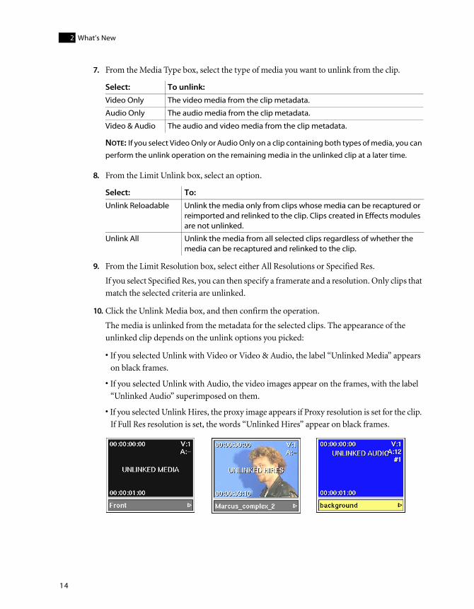
The media is unlinked from the metadata for the selected clips. The appearance of the unlinked clip depends on the unlink options you picked:
• If you selected Unlink with Video or Video & Audio, the label “Unlinked Media” appears on black frames.
• If you selected Unlink with Audio, the video images appear on the frames, with the label “Unlinked Audio” superimposed on them.
• If you selected Unlink Hires, the proxy image appears if Proxy resolution is set for the clip. If Full Res resolution is set, the words “Unlinked Hires” appear on black frames.
Select: To unlink:
Video Only The video media from the clip metadata.
Audio Only The audio media from the clip metadata.
Video & Audio The audio and video media from the clip metadata.
Select: To:
Unlink Reloadable Unlink the media only from clips whose media can be recaptured or reimported and relinked to the clip. Clips created in Effects modules are not unlinked.
Unlink All Unlink the media from all selected clips regardless of whether the media can be recaptured and relinked to the clip.

Generating Proxies in the Background
15
yww
Generating Proxies in the BackgroundWhen soft-importing your DPX files you can use Autodesk Backburner™ and Autodesk Burn™ to generate proxies in the background, allowing you to address other tasks in the application while the proxies are generated.
To generate proxies in the background:
Generating proxies in the background can be triggered from the Import Image and Recapture menus. Do one of the following:
• In the Import Image menu, enable Bg Proxies.
• In the Recapture menu, enable Background Proxies.
Hot Keys The following table lists hot keys introduced in this release.

What’s New2
16
These hot keys are not compatible with the previous release. To use these hot keys, you must create a new user.
Importing DPX Sequences for Data ConformThere is a new workflow designed specifically to accommodate importing or soft-importing DPX sequences generated from a film scanner. You can now use the new Recursive Scan option in conjunction with the new Tape Name options to import DPX sequences originating from different film reels in a single step. Used together, these features efficiently batch-capture file-based media in preparation for data conform from an EDL. The imported clips all have the correct source keycode, timecode, and tape name, making it easy to load your EDL and assemble the timeline for conforming and finishing.
To import DPX file sequences for data conform:
1. Open the Import Image menu.
2. Browse to the top-level directory that contains all the subdirectories and image sequences that you want to display.
Typically, all DPX sequences generated by a film scanner reside in a top-level <project> directory, sorted into subdirectories corresponding to tape name, resolution, and sometimes clip name, as follows: ./<project>/<tape>/<resolution>/*.######.dpx
3. From the Format box, select the DPX image type.
You can select any single, supported image type. The default type for image files is DPX because this is a DI standard that embeds source metadata in the file header. The Auto option is not supported with the Recursive Scan operation.
4. Optionally, enable Filter and enter the appropriate criteria to focus your search.
Operation Hot Key
Add note to clip on desktop V
Pan in Text module CTRL+SHIFT+SPACEBAR and drag
Swap segments on timeline S
Zoom in viewports CTRL+SPACEBAR and drag
NOTE: In a module’s animation view, the new zoom hot key replaces the ALT hot key.
Mute or unmute Action layers in the Layers List
ALT and click
Rotate Canvas in Layer Based Paint
ALT+SPACEBAR
Switch between straight and Hermite lines in Clip History
SHIFT+CTRL and click

Importing DPX Sequences for Data Conform
17
yww
The criteria is checked against the entire path. For example, if you enter *2048*, the filter will list only those sequences that reside under a directory path containing the string “2048”. In this case only 2K sequences are displayed while everything else, such as 1K proxies or thumbnails, is filtered out.
5. Enable Recursive Scan.
The directory scan begins. This may take some time to complete, depending on the size and quantity of subdirectories and files.

What’s New2
18
When the scan is complete, the Files list displays all detected files with the directory path relative to the top-level directory. The list is sorted alpha-numerically by path and file name.
HINT: For long file names that may be clipped in the browser, hold down the ALT key while
hovering over the file name. This displays the full file name in a floating window.
The results of the scan remain until you browse upwards to another directory, in which case the Recursive Scan option gets disabled.
6. From the File Timecode box, select DPX TC.
This will set the source timecode of the imported clip based on the timecode information in the DPX image file header.
7. From the Keycode box, select DPX KC.
a) Subdirectories in the scanned directory b) All nested subdirectories with full path
a) File Time Code box b) Keycode box c) Film Gauge box
a b
a b c

Importing DPX Sequences for Data Conform
19
yww
This allows DPX files that contain keycode data to be imported with their keycode data intact.
8. From the Film Gauge box, select the gauge corresponding to the source film from which the images originated.
This value is necessary because keycode values are assigned to each frame of the sequence differently depending on the film gauge.
9. Set the tape name for the imported clips.
You can either infer the tape name from a directory name or read the tape name from a DPX file header. Do one of the following:
• To infer the tape name from a directory name, from the Tape Name Option box, select Dir Tape, then use the Level field to configure the relative file path to the directory from which the tape name can be inferred.
This is designed to work with the directory structures that are output by film scanners. For example: ./<tape>/<resolution>/clip.######.dpx. In this case, selecting Up 2 Levels in the Level field would correctly identify the directory that corresponds to the tape name.
• To read the tape name from the DPX file header, from the Tape Name Option box, select DPX Tape.
The tape name is read from the Input Device Name field (field 38) in the header of the DPX file and is displayed in the Tape Name field.
Tape Name option box Level field
Tape Name option box Tape Name field
a b
a b

What’s New2
20
Note that there is currently no industry standard for embedding the tape name in the DPX header. Some film scanners, such as the ARRISCAN, write the tape name associated with a film frame into field 38 of the DPX header. Other scanners, for example, Imagica or Filmlight, allow field 38 to be user-definable although the default value is not the tape name.
NOTE: Before using the DPX Tape name feature, consult with your film scanner operator to
ensure compatibility.
10. Import or soft-import the sequences.
If you soft-import clips you can generate proxies in the background. This gives you the ability to assemble the timeline while proxy generation is taking place.
11. Once you have imported or soft-imported all the sequences, you can import the corresponding EDLs to assemble a clip with unlinked media, then relink the clip to the DPX files in the reel.
Layer-Based Paint (Linux only)The following features are now supported in layer-based Paint.
Rotation field — You can now rotate the canvas, making it easier to paint on any part of your image. Use the Rotation field to enter a value or press ALT+SPACEBAR and drag in your image to rotate the canvas.
Both button — When using custom brushes, you now have the option of painting on both the front and matte layers simultaneously. When the Both button is enabled, custom brush strokes applied to the front layer are also applied to the matte layer, and vice-versa.
a) Rotation field b) Both button
a b

Lustre Color Management
21
yww
Lustre Color ManagementYou can now use the Lustre Color Management package for monitor calibration, high-integrity display, and accurate colour space conversions. The package consists of a monitor calibration utility, and a range of generic display and conversion lookup tables (LUTs). The generic nature of the LUTs implies that results may not match a specific lab process. However, they will deliver accurate print film rendition.
The monitor calibration utility allows you to calibrate computer CRT and LCD monitors either locally or remotely. The remote feature makes it possible to calibrate monitors for Linux and IRIX machines without the use of a USB extender.
The LUTs allow you to simulate the colour space of a specific film stock relative to a display device. Display LUTs allow you to view the effect without rendering, whereas conversion LUTs create a new clip for use in a subsequent step of the production chain.
Lustre Color Management is not supported on the following products:
• Smoke HD
• Flint
See the Lustre Color Management User’s Guide available on the Autodesk Web site at www.autodesk.com/discreet-documentation.
QuickTime Support for LinuxYou can now directly import and export QuickTime® files from Autodesk Editing or Effects applications running on Linux® systems.
During import, the codec flag and other detected metadata for a supported movie appears in the source metadata fields in the Import Image menu. Otherwise, a message appears indicating that the movie cannot be imported.
Importing QuickTime FilesIn the Import Image menu, you can now select QuickTime to import a variety of QuickTime file types into the application. Quicktime files can be encoded with any of a number of different CODECs. The following are the QuickTime CODECs that are now supported on import.
Broadcast CODEC CODEC Flag Comment
10-bit Packed YUV 4:4:4 v410
10-bit Packed YUV 4:2:2 v210 Blackmagic 10-bit compatible
8-bit Planar YUV 4:4:4 v308
8-bit Planar YUV 4:4:4:4 v408

What’s New2
22
8-bit Packed YUV 4:2:2 yuv2 Blackmagic 8-bit compatible
8-bit Packed YUV 4:2:2 2vuy
DV 25 NTSC dvc
DV 25 PAL dvcp, dvpp
DVCPRO 50 NTSC dv5n Panasonic® standard
DVCPRO 50 PAL dv5p Panasonic standard
File CODEC CODEC Flag Comment
PhotoJPEG RTJ0 Blackmagic RT PhotoJPEG compatible
MJPEG MJPG, mjpg, JPEG, jpeg, dmb1, AVDJ
Blackmagic JPEG compatible
PNG png Portable Network Graphic sequence (no alpha support)
PNGA pngalpha Portable Network Graphic sequence (with alpha support)
RGB Uncompressed raw No alpha support
RGBA Uncompressed rawalpha With alpha support
Web CODEC CODEC Flag Comment
MPEG-1 mpg1, MPG1, pim1, PIM1
MPEG-4 mp4v; divx; DIV1; div1; MP4S;M4S2; m4s2; xvid; XVID; XviD; DX50; dx50; DIVX; MP4V
MSMpeg 4v3 (DivX) DIV1, div1, MPG4, mpg4, DIV2, div2, MP42, mp42, DIV3, div3, DIV4, div4, DIV5, div5, DIV6, div6, MPG3, mpg3, MP43, mp43, AP41, ap41, MJPG
Quicktime Planar RGB 8BPS
Apple Video rpza
Apple Graphics smc
RLE rle
Cinepak cvid
Audio CODEC CODEC Flag Comment
IAM4 ima4
Raw 8-bit audio rawaudio
Broadcast CODEC CODEC Flag Comment

QuickTime Support for Linux
23
yww
NOTE: A clip that is imported using an unsupported frame rate will be converted to the frame rate
specified for the current project. This will cause the clip to appear out of sync with its audio. A
comment specifying the original frame rate is added to the clip "notes", providing the ratio needed
if you choose to re-time the video.
Exporting QuickTime FilesIn the Export Image menu, you can now select QuickTime, and then select a supported QuickTime file type, when exporting an image file. Audio is always exported using the Twos audio codec; this is an uncompressed audio codec developed for the Linux operating system. The following are the QuickTime CODECs that are supported on export.
Twos twos
Ulaw ulaw
Sowt sowt
Alaw alaw
16-bit PCM in16
Linear PCM (QT 7) lpcm
Ogg Vorbis (qt4l compatible)
vorbis
Ogg Vorbis (qt components compatible)
vorbis_qt
Mpeg Layer 2 Audio mp2
QDM2 Audio qdm2
Apple lossless alac
McRowsoft ADPCM adpcm (ms)
ADPCM ima WAV ima adpcm (wav)
Broadcast CODEC CODEC Flag Comment
10-bit Packed YUV 4:4:4 v410
10-bit Packed YUV 4:2:2 v210 Blackmagic 10-bit compatible
8-bit Planar YUV 4:4:4 v308
8-bit Packed YUV 4:2:2 yuv2 Blackmagic 8-bit compatible
8-bit Packed YUV 4:2:2 2vuy Blackmagic 8-bit compatible
DV 25 NTSC dvc
DV 25 PAL dvcp, dvpp
DVCPRO 50 NTSC dv5n Panasonic standard
DVCPRO 50 PAL dv5p Panasonic standard
Audio CODEC CODEC Flag Comment

What’s New2
24
Searching for Mixed Resolution SourcesYou can now search for clips that contain mixed resolution sources and mixed resolution history sources.
Searching for mixed resolution sources can be helpful when trying to identify sources that prevent a clip from being archived.
You can search the desktop or clip library.
To search the desktop for clips with mixed resolution sources:
1. From the desktop, click Search.
File CODEC CODEC Flag Comment
MPEG-4 mp4v
MSMpeg 4v3 DIV3 DivX 3 MPEG-4 compatible
PhotoJPEG rtjpeg Blackmagic RT PhotoJPEG compatible
MJPEG MJPG Blackmagic JPEG compatible
PNG png Portable Network Graphic sequence (no alpha support)
PNGA pngalpha Portable Network Graphic sequence (with alpha support)
RGB Uncompressed raw No alpha support
RGBA Uncompressed rawalpha With alpha support
Audio CODEC CODEC Flag Comment
Twos twos Audio is always exported using Twos, which is an uncompressed audio codec developed for the Linux operating system.

Searching for Mixed Resolution Sources
25
yww
The Search menu appears.
2. Select the following search options.
3. From the Search Area box, select to search either the desktop or all libraries belonging to the project, and then click Search.
NOTE: If you want to search only the current library, perform the search from the library itself.
If a match is found, the number of matches appears in the message bar and the cursor changes to a white arrow.
4. Click the reel where you want the mixed resolution clips to appear.
To search the clip library for clips with mixed resolution sources:
1. From the clip library, click Search.
a) Search Mode box b) Search Criteria box c) Argument option box d) Search Area box
Select: From:
Clip The Search Mode box.
Mixed Res The Search Criteria box.
Contains Argument box.
d
a b c

What’s New2
26
The Search menu appears.
2. Select Mixed Res from the Search Criteria box and then select Contains from the Argument option box
3. Click Search.
If a match is found, the number of matches appears in the message bar and the clips are selected.
For information on other search options, refer to “Searching the Desktop” in the “Desktop” chapter and “Searching for Clips” in the “Clip Library” chapter.
Setting Desktop PreferencesYou can now use an automatic timestamp to rename untitled clips to make it easier to distinguish multiple <Untitled> clips. You can set how you want to name untitled clips by selecting an option from the Untitled Clip Name box in the System menu.
After you set this preference, any new untitled clips are renamed according to your selection.
a) Search Criteria box b) Argument option box
a) Untitled Clip Name box
Select: To name your clip:
Keep Untitled <Untitled>
Use Date & Time yyyy/mm/dd hh:mm
Use Date yyyy/mm/dd
Use Time hh:mm
a b
a

Batch Timeline Editing
27
yww
NOTE: When exporting a clip with a timestamp name, all unsupported characters (/, :, and spaces)
are replaced by underscores.
Batch Timeline EditingThe following features are now supported when editing on the Batch timeline.
Swapping Batch Timeline ElementsYou can now quickly swap elements on the Batch timeline using hot keys instead of moving them gesturally. If segments contain segment effects, they are swapped as well.
The following elements can be swapped:
• Video segments
• Audio segments
• Contiguous sequences of elements
• Video transitions (unless they start or end a contiguous sequence of elements)
• Audio transitions
Elements must be compatible to be swapped. Compatible elements are:
• Video segments
• Audio segments
• Video transitions
• Audio transitions
The following elements cannot be swapped:
• Gaps (unless they are between elements in a contiguous sequence)
• Cuts
• Cue marks
• Individual soft effects

What’s New2
28
To swap Batch timeline elements:
1. Select two elements belonging to the same family.
A contiguous sequence of elements is treated as a single element as long as the transition between the elements is selected. A gap can be part of a contiguous element as long as it is not at the beginning or end of the sequence.
2. Press S.
The elements are swapped according to the ripple setting. If the segments contain any soft effects, they are swapped as well.
If Ripple is disabled, the segments are timewarped using a Constant Fit-to-Fill timewarp to fill each other’s location. If there is already a timewarp on the segment, the timewarp is replaced by the Constant Fit-to-Fill timewarp.
Contiguous sequences ripple regardless of Ripple status because they cannot be timewarped.
Transitions keep their alignment but their duration changes based on the head and tail frames of the destination segments.
a) Segments selected to be swapped
a) Selected segments are swapped according to Ripple setting
b) Ripple setting
a
a
b

Batch Timeline Editing
29
yww
Snapping to Batch Timeline ElementsWhen you insert edits on the Batch timeline gesturally, you now have more control of where your edits will go. New Snap options allow you to snap to in or out points or to the closest element.
To snap to a Batch timeline element:
1. In the Batch Timeline, select a Snap option (or press ALT+M to cycle through the Snap options).
2. Select a source clip in the schematic or a segment on the timeline.
3. Do one of the following:
• Press ALT+SHIFT and drag the source clip from the schematic to the timeline so that the cursor is close to where you want to make an insertion,
• Drag the segment so that the cursor is close to where you want to make an insertion on the timeline,
Note that the location of the cursor on the timeline determines whether the segment’s head or tail snaps to the element.
Select: To snap the segment:
Snap Mark To the closest in or out point on the timeline.
Snap Close To the closest of the following: transition, positioner, in point, out point. The cursor must be within a given range of these elements on the timeline for this option to work.
a) In point b) Out point c) Cyan segment selected
a b c

What’s New2
30
The cursor changes to a four-headed green arrow and the timecode and track where the segment will go appear below the arrow.
4. Release the cursor when you are satisfied with the location of the segment.
The timeline is updated with the new segment.
For information on the other Snap options, see “Inserting and Overwriting Entire Clips” in the “Batch Timeline” chapter of the User’s Guide.
Zooming in ViewportsAn updated hot key combination now allows you to zoom in and out of a viewport more quickly. You can zoom in any of the following viewports:
• A module’s image window (you can zoom in any view, for example, Result or Front)
• A module’s schematic view
• A module’s animation view
• The Player
a) Snap Mark option b) Cyan segment will snap to closest in or out point
a) Head of Cyan segment snapped to in point of Red segment
a b
a

Zooming in Viewports
31
yww
To zoom in a viewport:
Press CTRL+SPACEBAR and drag right to zoom in or left to zoom out.
NOTE: In the Text module, this new zoom hot key replaces the pan hot key. The new hot key for
panning in Text is CTRL+SHIFT+SPACEBAR. In a module’s animation view, the new zoom hot key
replaces the ALT hot key.

What’s New2
32

33
3D Camera Tracking (Inferno and Flame)
SummaryAbout 3D Camera Tracking . . . . . . . . . . . . . . . . . . . . . . . . . . . . . . . . . . . . . . . . . . . . . . . 33
Accessing the 3D Tracker . . . . . . . . . . . . . . . . . . . . . . . . . . . . . . . . . . . . . . . . . . . . . . . . . 33
Preparing to Track . . . . . . . . . . . . . . . . . . . . . . . . . . . . . . . . . . . . . . . . . . . . . . . . . . . . . . . 34
Auto 3D Tracking . . . . . . . . . . . . . . . . . . . . . . . . . . . . . . . . . . . . . . . . . . . . . . . . . . . . . . . . 35
Manual 3D Tracking . . . . . . . . . . . . . . . . . . . . . . . . . . . . . . . . . . . . . . . . . . . . . . . . . . . . . 41
About 3D Camera TrackingUse Action’s 3D tracker to compute the path of live-action camera motion in 3D space. Using the calculated position and motion of the virtual camera, you can match image sequences perfectly, placing any element in the scene. The perspective of the element you place in the scene changes with the perspective of the background as the camera moves. The virtual camera motion is intended to be identical to the motion of the actual camera that shot the scene.
Accessing the 3D TrackerThe 3D tracker is accessed though Action’s Camera menu.
To access the 3D tracker:
1. In Action, click Camera.
2. In the Camera menu, enable 3D Track.

3D Camera Tracking (Inferno and Flame)3
34
The 3D tracking controls appear.
3. From the 3D Tracker Option box, select the Auto or Manual tracker.
Preparing to TrackA good 3D tracking result is often footage dependant, therefore you may decide to use the auto or manual 3D tracker. In most cases, the auto 3D tracker gives good results. In some instances, such as when the motion is confined to the axes, and there is little or no perspective rotation, the manual tracker may be a better choice.
Here are some things to keep in mind that can improve your 3D track:
• The 3D tracker works best when tracking an image sequence that has a moving camera or environment. Objects or actors that are moving in an image sequence can cause bad results. You should mask these objects so that they are ignored in the tracking process. You should also mask any logos or watermarks in your image sequence.
• The 3D tracker analyses based on point-like and corner-like image features. Balls, spheres, lines, and smooth surfaces are not considered.
• You should crop out any black areas around your image (such as letterbox areas). When cropping, it is very important to keep the optical centre of the image in the centre, that is, the crop should be symmetrical in both dimensions.
• To be able to convert the tracking results correctly, the resolution and aspect ratio of the image being analysed must match the resolution and aspect ratio set in the Action Setup menu. To see these options, click Setup, then swipe down to see the Render Options menu.
• 3D tracking analyses each frame extensively and with high resolution clips, the process can be lengthy. Unlike 2D tracking, however, you are not required to analyse full-resolution clips. In
a) 3D Tracker Option box
a

Auto 3D Tracking
35
yww
many cases, analysing proxies will produce acceptable 3D tracking results, in a fraction of the time that would be required for the full-resolution clips.
Auto 3D TrackingThe first step in 3D auto tracking is to perform your initial tracking. Depending on the result, you may or may not need to fine-tune the track.
To create a 3D auto track:
1. From the 3D Tracker option box, select Auto.
2. In the Track Layer field, specify the layer number of the clip you want to track. A value of 0 indicates that the Back clip will be tracked.
3. Enable Use Matte and specify the Matte Layer if you want to use a matte to delimit the tracking results. For example, in an image sequence of a busy street, you can create a matte of moving elements (such as cars and people) to isolate this area from the analysis.
White areas of the matte will be considered for calculating the solution; black areas will be ignored (unless you selected Matte Invert from the Matte Clip box).
NOTE: You must use a matte made from real frames. Keyer or Gmask outputs will not work as
a matte for 3D tracking.

3D Camera Tracking (Inferno and Flame)3
36
4. If needed, select Analysis options.
5. If needed, adjust the scale of the trackers.
Smaller trackers can speed up the calculation, while larger trackers make the analysis more robust with regard to image noise and variations. A general rule is to increase the scale of the trackers when tracking high-resolution footage (2K or larger) that contains more noise or less sharpness.
6. From the Icons section, select tracker display options:
You can also adjust the transparency of the trackers and points in your image.
7. Click Track. Tracking occurs in the background, allowing you to continue working while tracking.
You can see a progress indicator beside the Track button. You can interrupt the analysis and resume it by clicking Track again. After tracking has completed and been confirmed, the Track button changes to Calibrate, and you can see the 2D tracks (the blue squares in the following example) and 3D points (green crosses) in your image, provided that you chose to
Enable: To:
Zoom Calculate the zoom value of the reconstructed camera for each frame (assuming the camera that shot the tracked clip has a variable zoom value). By default, Zoom isn’t enabled (that is, the track is analysed with a fixed zoom).
Backward Track the image sequence backward after the forward tracking has completed. This option takes longer, but you may get better results.
Enable: To display:
Trackers 2D tracks in your image. Use the colour pot to select the colour of the tracks.
Points 3D points in your image. Use the colour pot to select the colour of the points.

Auto 3D Tracking
37
yww
display them, and that the Camera menu is active and you are in Result, Front, or Back view mode.
8. If you are satisfied with the results of the tracking analysis, proceed to “Defining the Auto Track Ground Plane” on page 40 and “Converting the 3D Auto Tracking Results” on page 41. If you need to fine-tune your track, see the next section.
Fine-Tuning the 3D Auto TrackIf the initial auto tracking does not give desired results, you can use some or all of the Selection options to calibrate and refine your track analysis. These procedures are not necessarily required, but depending on your image and the initial tracking, may give better tracking results.
Image courtesy of Behavior Communications Inc.

3D Camera Tracking (Inferno and Flame)3
38
To fine-tune the 3D auto track:
1. Use the Quality slider to adjust the number of good trackers that are kept. The higher the quality setting, trackers that are likely to be less reliable are selected, such as trackers that drift off their initial reference point. Click Delete to delete the selected trackers.
Trackers of lower quality may hinder the accuracy of the camera tracking.
NOTE: After you have made a change that requires the 3D tracking analysis to be refined or
calibrated, notice that the LED next to the Refine and Calibrate buttons turns yellow. This
signifies that a Refine or Calibrate is required, but you do not have to perform it until you have
completed your tracker selections.
2. Adjust the Short slider to select short duration trackers, that is, trackers that only track a feature for a few frames. Click Delete to delete the selected trackers, leaving the longer duration trackers intact.
3. You can manually select and delete trackers from the image that you feel are not tracking properly. Do one of the following:
• To select an individual tracker, click the tracker, and then click Delete.
• To select multiple trackers in the same area, CTRL-drag a selection box over a series of trackers, and then click Delete.
• To add another tracker to a multiple selection, SHIFT-click the tracker, and the click Delete.
• With Delete mode selected in the Edit Mode box, select trackers in the image.

Auto 3D Tracking
39
yww
4. If you want to manually add a tracker at certain area that you want to track, enable Add and click on your chosen area of the image to automatically track from this area.
A tracker may or may not be added, depending on the ability of the track analysis algorithm to find an appropriate feature to track in this area.
5. If the analysis creates different trackers that refer to the same feature in the image, you can link these trackers. Press SHIFT and select two or more trackers from the image, and then click Link.
For example, an element leaving the scene at frame 28 and returning at frame 50 may result in two different trackers attached to the same element in the image. In this case, select the trackers and click Link to teach the algorithm that these trackers are the same.
To refine or calibrate the 3D track:
Depending on the changes you have made, you can choose to refine or calibrate the 3D track. Do one or both of the following:
• Click Refine.
The track analysis uses the current results as a starting point, and refines from this point.
a) Refine button b) Pixel Error value
a b

3D Camera Tracking (Inferno and Flame)3
40
Click Refine again to stop the process once an acceptable pixel error value is reached. The pixel error value is a representation of the distance of the 2D tracks from the repositioned 3D points.
HINT: The refine process is footage-dependant, so your acceptable pixel error value may
change depending on what you are tracking. Since the refine process continues until you stop
it, as a general rule, if the pixel error value doesn’t change for a length of time (for example, 30
seconds), you can stop the refine process. The lower the pixel error value, the more accurate
the reconstructed track is.
• Click Calibrate.
NOTE: The calibrate operation deletes all previous points and starts over based on the new
information. Depending on your footage, and how many trackers you added, deleted, or
linked, multiple calibrations may yield different results.
Defining the Auto Track Ground PlaneAlthough it is not mandatory to define a ground plane in your image, it helps orient the reconstruction of the cameras.
To define the auto track ground plane:
1. Enable Define.

Manual 3D Tracking
41
yww
2. Select a minimum of three points in the image that represent the plane of the X/Z axes, such as the ground, a table, or any flat surface.
The selected points appear as red squares with white crosses.
HINT: You may want to temporarily disable the tracker and point display options (or raise the
transparency level) to help you find and select the plane points. You can also change the plane
display size from the Icons section.
3. Use the Position and Rotation controls to define the orientation of the ground plane.
4. Use the Scale slider to specify the scale of the scene.
5. Disable Define.
The plane is displayed as a red grid.
Converting the 3D Auto Tracking ResultsWhen you are satisfied with the results of the 3D auto tracking analysis, you can convert the selected reconstructed points to actual axes in the Action schematic to use in your scene.
To covert the 3D tracking results:
1. Select the desired points in the image (according to how you want to use them) and click Convert. Selected points are displayed as green squares with red crosses.
Selected points are converted to axes and the analysed camera motion is applied to a new camera.
NOTE: If no points are selected when you click Convert, a ground plane axis is created, and the
camera motion is applied to a new camera.
2. Exit the 3DTrack menu. You can then make the new camera active, and use the created axes to view the reconstructed camera motion.
Remember that it is the camera that is moving and not the points in the clip. You can attach objects such as surfaces, 3D text, and 3D models to the new axes to help position them in 3D space.
Manual 3D TrackingBefore you start manual 3D tracking, you should examine the clip closely to determine the points you want to track. The quality of the 2D track has a direct impact on the 3D tracking result, so it is important that you have a strategy for positioning the trackers in the clip sequence. Use the Stabilizer to track and stabilize the clip as accurately as possible. See the “Tracking and Stabilizing” chapter in your User’s Guide for more information.

3D Camera Tracking (Inferno and Flame)3
42
For optimum results, each frame in the clip you are tracking must contain at least six track points. In the Stabilizer, this means six trackers are enabled. Also, at least two frames in the clip sequence must have a minimum of eight trackers, and these two reference frames should show the widest camera movement.
When tracking, the more track points you have in each frame, the smoother and more accurate the tracking result will be. As you place the trackers on the image, consider the following guidelines:
• Scatter the trackers by placing them on markings, corners, and shadows over the widest area possible, while concentrating on arranging the trackers so that they represent 3D space. For example, avoid placing all trackers on the floor; place them on walls and other objects in the scene, as well as on the floor.
• Create a sense of depth by positioning trackers on points that lie in different planes, as well as on points located in the foreground and the background of the sequence.
• Avoid tracking points such as highlights or a point where the foreground and a background object meet, as they do not represent physical 3D points.
• Balance the number of trackers within each frame of the sequence so that as you move through the clip, some points leave the frame and other points appear in the frame. However, maintain a balance so that too many points do not leave or enter the frame at the same time.
• Avoid positioning the trackers in uniform areas or on linear edges where the track points may slide along the edge.
To set up trackers:
1. In Action, click Camera.
2. In the Camera menu, enable 3D Track.
The 3D tracking controls appear.
3. From the 3D Tracker option box, select Manual.
4. In the 3D tracking controls, click Stabilizer.
The Stabilizer menu appears.
5. Add trackers to the scene by clicking Add Tracker.
NOTE: You can track points only on the back clip that you load in Action.
6. Drag each tracker to a position on the image following the guidelines described in “Basic Manual 3D Tracking” on page 43.
You should have at least six trackers active at any one time, and at least two frames should have eight active trackers.

Manual 3D Tracking
43
yww
7. In the Stabilizer menu, click Analyse to process the 2D tracking path and check your result.
If the tracking is not correct, try standard tracking techniques as described in the “Tracking and Stabilizing” chapter of your User’s Guide.
8. Click Return to return to the 3D tracking controls in Action’s Camera menu.
When you track a pattern that appears to drift or stray, you should set more intermediate trackers in the frames of the sequence, and ensure both the first and the last reference frames are set properly.
Basic Manual 3D TrackingManual 3D tracking is computed by generating an orientation based on the trackers you defined. This orientation is defined by keyframes. The manual 3D tracker creates keyframes with the 3D track points. If the focal length is unknown, at least eight 3D points are needed. These points should not all lie on the same plane.
Once keyframes and 3D points are computed, the intermediate frames are computed by first interpolating between the keyframes, and then refining the camera properties using the estimated 3D point information.
You do not need to specify a coordinate system to create manual 3D tracking.
To compute basic manual tracking:
1. Define markers as described in “Manual 3D Tracking” on page 41.
NOTE: If the focal length is unknown, at least eight 3D points are needed. These points should
not all lie on the same plane.
2. Click Camera to open the Camera menu.
3. In Action’s Camera menu, enable 3D Track.
4. Click Frames to open the Frames menu.
5. From the 3D Tracker option box, select Manual.

3D Camera Tracking (Inferno and Flame)3
44
6. Click Initialise Frames.
Initialise Frames verifies that there are enough trackers in the scene and checks that there is enough spacing between the defined trackers. If you have not placed sufficient trackers in your scene, you will get an error message.
If you have enough trackers, the scene will be tracked and keyframes will be created for the camera. These keyframes can also be adjusted manually.
7. Click Analysis to open the Analysis menu.
8. Click Track Camera to track points and process the 3D tracking result.
Tracking the camera computes the 3D coordinates of the points that you tracked earlier. The manual 3D tracking analysis also calculates the tracking coordinates of the two references frames, the keyframes, and all the frames in the clip.
In general, you should let the manual 3D tracker choose the keyframes when you click the Initialise Frames button. In cases where the camera motion is jittery, you can position the keyframes manually. Ideally, adjust your 2D tracks in the Stabilizer to ensure the camera motion is as smooth as possible.
You can change the number of keyframes and you can specify your own keyframes. If you specify your own keyframes:
• There should be enough keyframes to “cover” all the tracks. However, too many keyframes may slow the tracking process. Very few keyframes are needed, especially when the camera movement is very smooth.
• Keyframes should cover the movement in the sequence.
• There should be a keyframe each time a track “leaves” or “enters” an image.
NOTE: A good 2D tracking result provides an excellent 3D track with keyframes set at every 5
frames or so.
Manual 3D Tracking
45
yww
Once the manual 3D tracking is computed, you can specify a coordinate system and apply it without resolving the tracking again. The camera and resulting axes are re-oriented without recomputing the tracking.
Advanced Manual 3D TrackingIf the basic manual tracking procedure is not as desired, or you want to tweak your results, you can perform several procedures to make your manual 3D tracking more accurate. These procedures include the establishing of an origin, and setting references and relations between trackers.
You must establish an origin and a set of reference coordinates (x,y,z) to track the distance an object moves in space—similar to the Cartesian coordinate system where the origin is (0, 0, 0). All other track points are relative to the origin throughout the manual 3D tracking process.
NOTE: Remember that it is the camera that is moving and not the points in the clip.
In Action, the distance between two objects helps define the scaling of the coordinate system. The change in distance between track points for each frame in a live-action clip determines how the 3D tracker will track an object.
When changing tracking coordinate settings, you do not need to retrack the camera.
After the manual 3D tracking is computed, you can specify a coordinate system and apply it without resolving the tracking again. The camera and resulting axes are re-oriented without recomputing the tracking.
Defining CoordinatesYou specify the manual 3D tracking coordinate system and point of origin in the Coordinates menu.

3D Camera Tracking (Inferno and Flame)3
46
The Coordinates controls are described as follows.
Origin box — Specifies the track point that sets the origin of the coordinate system. This should be a point that is easy to reference in the scene such as a point in the centre of the floor or the centre of a wall.
The Origin box lists the track points you added in the Stabilizer. If you added 12 track points to the scene, track points 1 through 12 are available in the list.
Distance boxes and Is field — Selects the track points to use for establishing the 3D tracking scale in the coordinate system. In the Is field, type a value that best represents the actual distance between the two track points selected in the Distance boxes.
Enable button — Allows you to access the Coordinates menu. The Set button is only visible once a successful tracking has been done.
Set button — Applies the newly entered values in the Coordinate menu.
To set the origin and distance:
1. In Action’s Camera menu, enable 3D Track.
The 3D tracking controls appear.
2. From the 3D Tracker option box, select Manual.
3. In the manual 3D tracking controls, click Coordinates.
The Coordinates menu is displayed.
4. Click Enable to gain access to the Coordinates menu.
5. In the Origin box, select the track point that sets the origin of the coordinate system.
a) Origin box c) Is field e) Set button
b) Distance boxes d) Enable button
a
cb d e

Manual 3D Tracking
47
yww
6. In the From box and To box of the Distance area, select the track points to use for measuring the distance and setting the 3D tracking scale for the coordinate system.
7. In the Is field, type a value for the distance between the From and To track points.
Because the camera distance and the field of view are directly related to the distance, consider the placement of the From and To track points with respect to the footage. Are the track points far in the back of the footage, such as on a building across a river? In this case, the value would be larger than, say, if the points were closer to the camera.
At first, you may have to try an approximate value and then experiment based on the results.
Defining AxesYou define a coordinate system to make it easier and more intuitive for inserting a virtual object or a 3D model in the scene. For example, if you want to place a 3D model on a flat surface such as a table, you should specify two coordinate directions such as coordinate X and Z, which represent the plane of that surface. The 3D tracker determines the third axis to complete the 3D coordinate system.
When specifying the two coordinate directions, such as the X-axis and Z-axis, use one common track point for both axes to establish a true coordinate system.
NOTE: Beware of negative and positive directions when specifying track points for the X, Y, or Z-
axis. For example, if you specify points for the Y-axis, pick the track point whose Y-coordinate value
is less than the second track point.
To define the axis:
1. Click Camera.
2. In the Axes area of the Coordinates menu, set up a coordinate system by selecting one axis from the Axis1 box and another axis from the Axis2 box.
a) Axis 1 box b) Axis 2 box c) Traversal Point boxes
c
a b

3D Camera Tracking (Inferno and Flame)3
48
3. From the Traversal Point boxes, for each axis, identify two points through which the selected axis passes.
Defining Relations between Track Points for Manual TrackingTo help the manual 3D tracker calculate relations between points, you can provide it with hints about the position and relationship of track points over several frames in a clip sequence. You establish track point relations by selecting the axes that track points have in common. Some track points can share the same Y-axis while a different set of track points can share the same X-axis value.
Define track point relations only after you obtain a result by setting up the 2D trackers and establishing a coordinate system. At that time you can experiment with a few relations and different camera properties until you are satisfied with your result.
For each track point in the scene whose coordinates you do know, you can create a point relation and specify its precision. For example, you may know the distance between these track points based on manual measurements or from a map. Create a point relation for each track point using a set of coordinates and set their Precision to variable or fixed, depending on the accuracy of the survey data. For example, two candlesticks on a table are at the same height above the table and a point relation would indicate that track points 3 and 4 share the Y-axis.
Select: To:
Through 2 Points Specify the two track points through which Axis 1 or Axis 2 traverses.
From Origin To Specify the track point through which Axis 1 or Axis 2 traverses including the origin track point.
Normal To 3 Points Specify the three points in a plane that define the normal. The three points define the plane to which the normal is perpendicular. Use the right-hand method to determine the order. Consider the following example. Track points 3, 6, and 2 are counterclockwise and the Z-axis is normal to these points.

Manual 3D Tracking
49
yww
Avoid defining a point relation that has only one point and whose shared axis is Unknown as this provides little information to the 3D tracker.
You define track point relations in the Relations menu. The 3D tracker uses the enabled point relations.
To define track point relations:
1. In Action’s Camera menu, enable 3D Track.
2. From the 3D Tracker option box, select Manual.
Z
X
Y -Z
Track point 4(0, 20, 0)
Track point 3(10, 20, -20)
Track point 2(10, 0, -20)
Track point 1(0, 0, 0)

3D Camera Tracking (Inferno and Flame)3
50
3. In the 3D tracking manual controls that appear, click Relations.
4. Click Create New to add a relation to the list of relations in the Relations box.
The first new relation you create appears in the Relation box and is enabled by default.
As you add new point relations, select the relation in the Relation box and click Enable to define or modify the relation. Try using different track points than the ones you used when defining the coordinates.
5. In the Track Points column, select a track point and click to add it to the Related Points column.
The number of track points that appear in this column corresponds to the trackers that are enabled in the Stabilizer.
6. In the Shared Axis box, select the axis shared by the related track points: Share X, Share Y, or Share Z.
For the selected relation, the track points listed in the Related Points column share a common axis.
7. In the Precision box and Value field, select the value of the track point relation using one of the following precision types.
a) Create New button c) Shared Axis box e) Related Points column
b) Relations box d) Track Points column f ) Precision box
Select: To:
Fixed Keep the X or Y value that you specify in the Value field throughout the tracking. The 3D tracker does not modify this value. For example, when you select Share X, the Y value remains constant for the related points. This is the default.
b c
f
a
d e

Manual 3D Tracking
51
yww
8. Click Enable.
A track point can belong to several point relations: Share X, Share Y, or Share Z, but only one relation can be enabled at a time. If you try to enable a point relation that contains a track point already existing in another point relation, a message appears indicating the first point relation is disabled. For example, Relation 1 is defined by track 1 and track 2 that have a Share X relation. If you try to create another relation, Relation 2 for track 1 and track 2, you are prompted that Relation 1 will be disabled.
NOTE: If you already tracked the camera and later changed the trackers relations, you need to
retrack the camera. See “Analysing Manual 3D Tracks” on page 56 for more information.
Setting Camera Properties for Manual TrackingBefore analysing the manual 3D motion and tracking, you may want to define your camera. The camera represents the device used to acquire the sequence of images you are tracking. Typically, when you load a clip, the camera position, field of view (FOV), and point of interest (POI) are assigned to each frame in the clip by default. For the purposes of 3D tracking, a camera is characterized by its internal properties: the principle point, the pixel aspect ratio, the focal length, and the non-linear distortion.
The manual 3D tracker handles most camera motions including zoom, even when only a small change in position or direction of an object is caused by a change in the point of observation. For each camera parameter, you can choose to let the 3D tracker calculate the value automatically or you can specify the value yourself.
NOTE: If you changed the camera properties after tracking the camera, you need to retrack the
camera. See “Analysing Manual 3D Tracks” on page 56.
To set the camera properties, you use the manual 3D tracking Camera menus, which are part of the 3D tracking controls.
Initialised Estimate the value of the track point starting with the initial value that you specify in the Value field.
Unknown Compute the value of the track points automatically with the3D tracker without specifying a value.
Select: To:

3D Camera Tracking (Inferno and Flame)3
52
In the General Camera, Focal Length, and Distortion menus, you can define sets of values by selecting one of the following solving options from the Pixel Aspect Ratio box.
NOTE: The Camera Distortion menu excludes the Variable Initialised and Variable Unknown
options.
Defining the General CameraIf you already have information about the camera, you can specify this information before using the manual 3D tracker. When you provide information about the camera, the calculation and rendering is much faster than when the tracker has to calculate the properties itself.
To define the camera:
1. In the Camera menu, enable 3D Track.
2. From the 3D Tracker option box, select Manual.
3. In the manual 3D tracking manual controls, click Camera and then click General.
a) 3D tracking Camera menus b) Pixel Aspect Ratio box
Select: To:
Constant Initialised Let the 3D tracker estimate the value, starting from an approximate value that you specify. The value remains constant for all the frames in the sequence.
Constant Unknown Let the 3D tracker compute the value and keep the value constant for all the frames in the sequence.
Variable Initialised Let the 3D tracker estimate the value, starting from an approximate value that you provide. The value can change across the frames.
Variable Unknown Let the 3D tracker compute the value with no input from you. The value can change across the frames.
Fixed Use the value you provide with no modifications made by the 3D tracker.
a b

Manual 3D Tracking
53
yww
The General Camera menu appears.
4. In the General Camera menu, specify the camera film back.
The image resolution values change according to the Film Back settings.
5. Select an Aspect Ratio. You can define a fixed value, or use one of the solving options described in “Setting Camera Properties for Manual Tracking” on page 51.
Setting the Focal LengthSetting focal length constraints tells the manual 3D tracker that the focal length is constant throughout the clip sequence. If you know the film back and the camera, you can allow the 3D tracker to calculate the focal length automatically by setting it to Constant Initialised.
The film back sets the field of view and might change the focal length and distance of the camera from the scene; however, it should not affect the quality of the shot.
Viewing the scene from the Side view lets you see the frustum more clearly. In this way you can view the camera and the scene.
a) Film Back box c) Units box
b) Aspect Ratio box d) Width field
Use: To:
Film Back box Specify the image resolution.
Width field Specify the width of the film back.
Units box Identify the unit of measure: inches or millimeters.
ba
c d

3D Camera Tracking (Inferno and Flame)3
54
To set the focal length:
1. In the Camera menu, click Focal Length.
2. From the Focal Length box, select the focal length.
NOTE: Use the Variable options for camera zoom; if you do not know the camera, use Constant
Initialised.
3. In the Length field, enter the focal length and then select millimeters or inches in the Units box.
Setting Camera DistortionThe manual 3D tracker uses lens distortion so that tracking points that are positioned far from the principle point—or the centre of the image—are taken into account. The distortion is a radial value measured from the centre of the principle point.
If the footage you are tracking contains a lot of lens distortion—perhaps due to a very wide angle lens—set the distortion with respect to the principle point so that track points in distorted areas are tracked accurately by the manual 3D tracker.
a) Film Back b) Focal Length c) Camera
a) Focal Length box b) Units box
q θ is the angle that represents the field of view (FOV)
b
c
a
b
a

Manual 3D Tracking
55
yww
To set camera distortion:
1. In the Camera menu, click Distortion.
2. From the Principle Point box, select one of the following.
3. In the Principle Point X and Y fields, enter the X and Y coordinates in pixels of the principle point.
A value of 0,0 corresponds to the lower-left corner of the image.
4. From the Distortion box, select the lens distortion as follows.
5. In the Distortion field, enter a value for the distortion.
NOTE: The distortion is 0 at the location of the principle point.
a) Principle point b) Distortion point
Select: To:
Fixed Specify a principle point whose position does not change. Select this when you know the position.
Constant Initialised Specify an estimated value for the principle point whose position does not change. Select this if you do not know where the principle point is, for instance, if the image is cropped.
Constant Unknown Let the 3D tracker determine the principle point. Select this only after you analyse the 3D track using Constant Initialised and you are not satisfied with the result. If you are still not satisfied with the result after using Constant Unknown, try setting a few track point relations and use Constant Initialised again.
Select: To:
Fixed Specify a distortion whose value does not change.
Constant Initialised Specify an estimated value for the distortion that does not change.
Constant Unknown Let the manual 3D tracker determine the distortion.
a b

3D Camera Tracking (Inferno and Flame)3
56
Analysing Manual 3D TracksThe manual 3D tracking process computes the camera properties and reconstructs the 3D coordinates of the 2D points that are tracked in the Stabilizer. The manual 3D tracking analysis also calculates the tracking coordinates of the two references frames, the keyframes, and all the frames in the clip.
Most errors result from a poorly tracked clip in the Stabilizer or when coordinates are set incorrectly.
Use the Analysis menu to finalize the manual 3D tracking process by fine-tuning the trackers. To access the Analysis menu, click Analysis.
The Analysis controls are described as follows.
Track Camera button — Tracks the 3D track points and processes the 3D tracking result.
Residual column — Determines the difference in pixels between the 2D track and the calculated 3D track for each tracker in the clip sequence.
The value shown in the Residual column represents the difference in precision between the 2D track and the 3D track at the current frame.
Average column — Shows the average residual of the tracker over all frames in the clip.
CurResidual field — Shows the average residual of the selected tracker at the current frame.
Tracker column — Represents each tracker in the Stabilizer and each track point in the 3D tracking scene.
Enabled button — Activates or deactivates the tracker in the scene.
Threshold field — Sets a threshold value so that a red indicator appears in the timebar at frames where the average residual exceeds this value.
Reconstruct button — Creates an axis in 3D space for the selected tracker.
a) Track Camera button
a

Manual 3D Tracking
57
yww
To track the 3D camera and analyse the 3D tracking results:
1. In the manual 3D tracking manual controls, click Analysis.
2. In the Analysis menu, click Track Camera.
3. For each tracker, peruse the residual and average residual values.
Look at the 3D axes of your track points and determine if their appearance is viable for the 3D track. The coordinates of each track point axis should point in the directions you expect.
4. If the average residual value for a particular tracker exceeds the threshold, disable Enabled for the tracker. You can repeat this step for more than one tracker.
5. If you want to reanalyse the manual 3D track, in the schematic, delete all track Axis nodes.
6. If necessary, go to the Stabilizer and revise a few 2D trackers.
7. Go to the Coordinates menu and verify the coordinate system.
8. Return to the Frames menu, click Initialise Frames.
9. In the Analysis menu, click Track Camera.

3D Camera Tracking (Inferno and Flame)3
58

59
Lens Distortion
SummaryAbout Lens Distortion . . . . . . . . . . . . . . . . . . . . . . . . . . . . . . . . . . . . . . . . . . . . . . . . . . . . 59
Accessing the Lens Distort Batch Node . . . . . . . . . . . . . . . . . . . . . . . . . . . . . . . . . . . . 59
Performing a Perspective Rectification (or Distortion) . . . . . . . . . . . . . . . . . . . . . . 61
Rectifying an Image with Spline Analysis . . . . . . . . . . . . . . . . . . . . . . . . . . . . . . . . . . 63
About Lens DistortionLens distortion can be caused by differences in camera lenses or perspective irregularities that result in skewed angles. You can use the Lens Distort Batch node to rectify or simulate these types of distortions in your images.
Accessing the Lens Distort Batch NodeThe Lens Distort Batch Node is accessed through the Batch module.
To access the Lens Distort Batch node:
1. In the Main menu, click Processing.
2. In the Processing menu, click Batch.
3. Swipe the bar at the left of the Batch menu to display the node bars.
4. Scroll the Processing nodes bar with a click and drag until you see the Lens Distort node.
5. Drag the Lens Distort node to the Batch schematic.
6. Double-click the Lens Distort node.
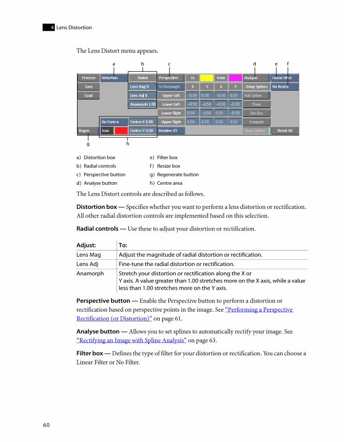
Lens Distortion4
60
The Lens Distort menu appears.
The Lens Distort controls are described as follows.
Distortion box — Specifies whether you want to perform a lens distortion or rectification. All other radial distortion controls are implemented based on this selection.
Radial controls — Use these to adjust your distortion or rectification.
Perspective button — Enable the Perspective button to perform a distortion or rectification based on perspective points in the image. See “Performing a Perspective Rectification (or Distortion)” on page 61.
Analyse button — Allows you to set splines to automatically rectify your image. See “Rectifying an Image with Spline Analysis” on page 63.
Filter box — Defines the type of filter for your distortion or rectification. You can choose a Linear Filter or No Filter.
a) Distortion box e) Filter box
b) Radial controls f ) Resize box
c) Perspective button g) Regenerate button
d) Analyse button h) Centre area
Adjust: To:
Lens Mag Adjust the magnitude of radial distortion or rectification.
Lens Adj Fine-tune the radial distortion or rectification.
Anamorph Stretch your distortion or rectification along the X or Y axis. A value greater than 1.00 stretches more on the X axis, while a value less than 1.00 stretches more on the Y axis.
a
h
b c d e f
g

Performing a Perspective Rectification (or Distortion)
61
yww
Resize box — Assigns the resize option you choose to apply to your image (if any distortion or rectification is present).
Regen button — Indicates whether the image is refreshed while fields are updated.
Centre area — Assigns the size of the centre box in your image. You can also change the colour of the center box by using the colour pot beside the Icon button.
After you make a selection in the Centre box, you can use the Centre X and Centre Y fields to move the centre of your image.
Performing a Perspective Rectification (or Distortion)You can rectify an image based on its perspective. You set four-corner source anchor points to features in the image that are distorted by the lens perspective, and map these points to a rectangle or a free-form four-corner destination shape. For example, you can correct a distorted wall by anchoring the points to the wall corners and automatically rectify it to be a rectangle.
NOTE: Although you can also perform a perspective distortion, best results usually occur when
performing a perspective rectification.
Select: To:
No Resize Keep the resolution of the image as is.
Best Fit Fit all of your distorted image (in the resolution of the front clip) without showing any black outside of the image.
Fit all Fit all of your distorted image (in the resolution of the front clip).
Resize Output Fit your distorted image in a different-sized output without losing any part of the image. If this option is selected, you can choose Optimal Resize, or you can set your preferred Width and Height.

Lens Distortion4
62
To perform a perspective rectification (or distortion):
1. Select Rectification (or Distortion) from the Distortion box.
2. Enable Perspective.
3. Select a Perspective type.
4. Set the Range type.
5. Set the X and Y values for your perspective type. You can also drag the anchor points directly in the image to set the various X and Y values.
Use the To and From colour pots to change the colours of the anchor points and guide lines, if needed.
HINT: You may find it easier to use two viewports in the image window for this procedure
(press ALT+2). Use Front view (F1) while working with any source shape (yellow anchor points
and guidelines), and use Result view (F4) while working with a Free Form destination shape
(pink anchor points and guidelines).
Select: To rectify (or distort) by:
To Rectangle Four-corner source anchor points mapped to a rectangle (you don’t have control of the destination rectangle).
Horizontal Preserving the horizontal edges of the original image and rectifying the vertical lines of the four-corner source shape to be vertical.
Vertical Preserving the vertical edges of the original image and rectifying the horizontal lines of the four-corner source shape to be horizontal.
Free Form The four-corner source anchor points mapped to a free-form four-corner destination shape.
Select: To set the X and Y range to:
Relative XY -0.5 to 0.5.
Absolute XY Half of the image size.

Rectifying an Image with Spline Analysis
63
yww
Rectifying an Image with Spline AnalysisYou can perform an automatic rectification of features in the image that should be straightened by computing a new alignment based on splines that you add.
To rectify an image with spline analysis:
1. Enable Analyse.
2. Click Add Spline.
Draw a spline in your image along a feature that should be straightened.
HINT: Splines are visible in the image if Show Splines is enabled.
3. Repeat Step 2 to add as many splines as needed. Click Clear to remove all selected splines.
4. Click Compute to analyse the image based on the splines you added.
5. Click Set Key to set a keyframe based on the result of the analysis.
6. Disable Analyse.
HINT: You can fine-tune your analysis with the Radial controls.

Lens Distortion4
64