Embed Size (px)
Citation preview
1734
09/10/18
THPPARTNERSHIPAUL
The Paul Davis Partnership, LLP286 Eldorado StreetMonterey, CA 93940
(831) 373-2784 FAX (831) 373-7459EMAIL: [email protected]
NEW EMPLOYEE BREAKROOM
SALINAS TRANSIT
110 SALINAS ST.SALINAS, CA 93901
CADD
09/10/18 REVISION 11
60 Garden Court Suite 210 Monterey, CA 93940T.831.646.3330 F.831.646.3336 www.acemb.com
Project No.
ONTEREY
NGINEERS
ONSULTING
EM
URUMA C
AY, INC.B
18028.00
E0.1
SYMBOLS,ABBREVIATIONS,LIGHT FIXTURESCHEDULE, CODES,STANDARDS, NOTES& SHEET INDEX
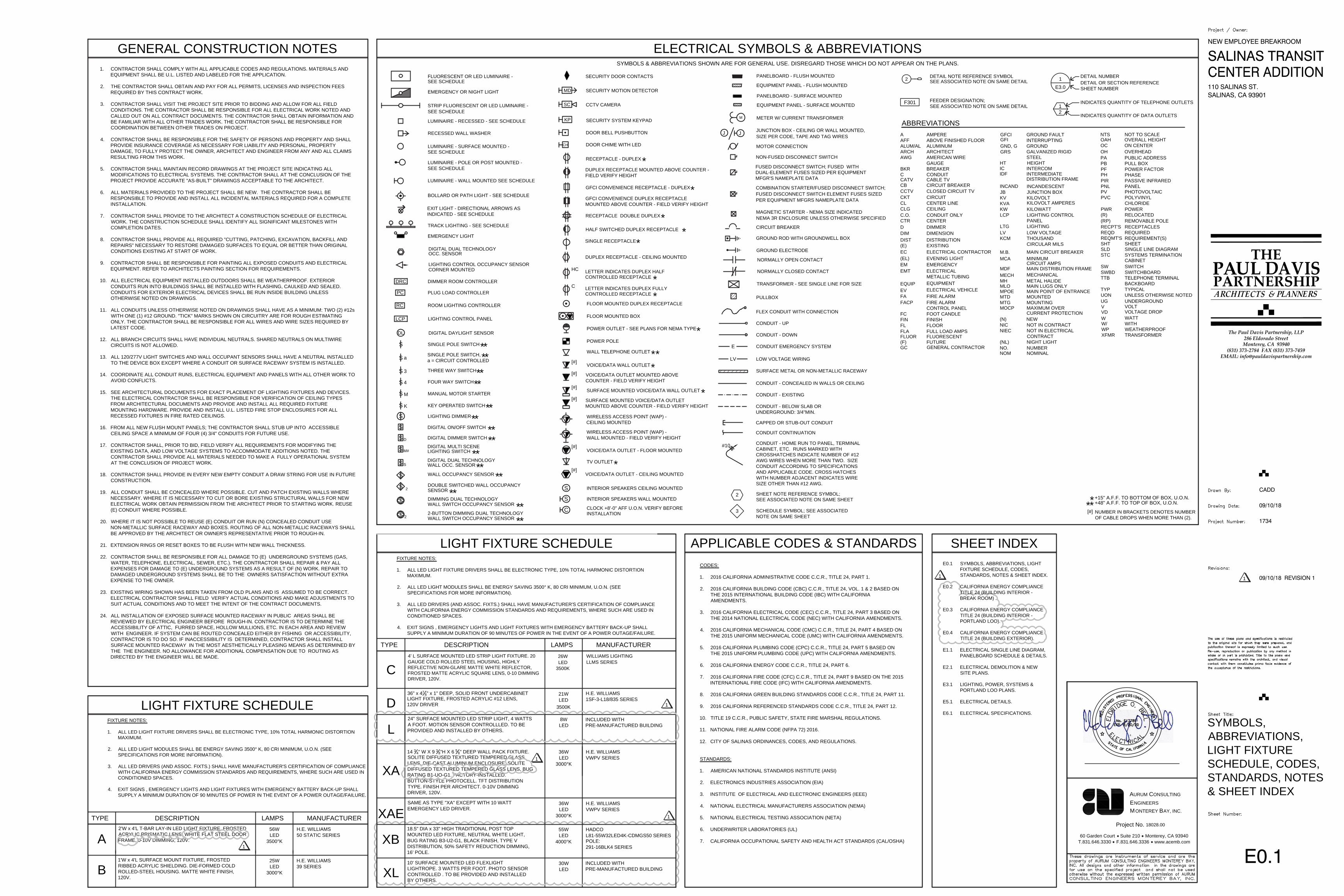
GENERAL CONSTRUCTION NOTES1. CONTRACTOR SHALL COMPLY WITH ALL APPLICABLE CODES AND REGULATIONS. MATERIALS AND
EQUIPMENT SHALL BE U.L. LISTED AND LABELED FOR THE APPLICATION.
2. THE CONTRACTOR SHALL OBTAIN AND PAY FOR ALL PERMITS, LICENSES AND INSPECTION FEESREQUIRED BY THIS CONTRACT WORK.
3. CONTRACTOR SHALL VISIT THE PROJECT SITE PRIOR TO BIDDING AND ALLOW FOR ALL FIELDCONDITIONS. THE CONTRACTOR SHALL BE RESPONSIBLE FOR ALL ELECTRICAL WORK NOTED ANDCALLED OUT ON ALL CONTRACT DOCUMENTS. THE CONTRACTOR SHALL OBTAIN INFORMATION ANDBE FAMILIAR WITH ALL OTHER TRADES WORK. THE CONTRACTOR SHALL BE RESPONSIBLE FORCOORDINATION BETWEEN OTHER TRADES ON PROJECT.
4. CONTRACTOR SHALL BE RESPONSIBLE FOR THE SAFETY OF PERSONS AND PROPERTY AND SHALLPROVIDE INSURANCE COVERAGE AS NECESSARY FOR LIABILITY AND PERSONAL, PROPERTYDAMAGE, TO FULLY PROTECT THE OWNER, ARCHITECT AND ENGINEER FROM ANY AND ALL CLAIMSRESULTING FROM THIS WORK.
5. CONTRACTOR SHALL MAINTAIN RECORD DRAWINGS AT THE PROJECT SITE INDICATING ALLMODIFICATIONS TO ELECTRICAL SYSTEMS. THE CONTRACTOR SHALL AT THE CONCLUSION OF THEPROJECT PROVIDE ACCURATE "AS-BUILT" DRAWINGS ACCEPTABLE TO THE ARCHITECT.
6. ALL MATERIALS PROVIDED TO THE PROJECT SHALL BE NEW. THE CONTRACTOR SHALL BERESPONSIBLE TO PROVIDE AND INSTALL ALL INCIDENTAL MATERIALS REQUIRED FOR A COMPLETEINSTALLATION.
7. CONTRACTOR SHALL PROVIDE TO THE ARCHITECT A CONSTRUCTION SCHEDULE OF ELECTRICALWORK. THE CONSTRUCTION SCHEDULE SHALL IDENTIFY ALL SIGNIFICANT MILESTONES WITHCOMPLETION DATES.
8. CONTRACTOR SHALL PROVIDE ALL REQUIRED "CUTTING, PATCHING, EXCAVATION, BACKFILL ANDREPAIRS" NECESSARY TO RESTORE DAMAGED SURFACES TO EQUAL OR BETTER THAN ORIGINALCONDITIONS EXISTING AT START OF WORK.
9. CONTRACTOR SHALL BE RESPONSIBLE FOR PAINTING ALL EXPOSED CONDUITS AND ELECTRICALEQUIPMENT. REFER TO ARCHITECTS PAINTING SECTION FOR REQUIREMENTS.
10. ALL ELECTRICAL EQUIPMENT INSTALLED OUTDOORS SHALL BE WEATHERPROOF. EXTERIORCONDUITS RUN INTO BUILDINGS SHALL BE INSTALLED WITH FLASHING, CAULKED AND SEALED.CONDUITS FOR EXTERIOR ELECTRICAL DEVICES SHALL BE RUN INSIDE BUILDING UNLESSOTHERWISE NOTED ON DRAWINGS.
11. ALL CONDUITS UNLESS OTHERWISE NOTED ON DRAWINGS SHALL HAVE AS A MINIMUM: TWO (2) #12sWITH ONE (1) #12 GROUND. "TICK" MARKS SHOWN ON CIRCUITRY ARE FOR ROUGH ESTIMATINGONLY. THE CONTRACTOR SHALL BE RESPONSIBLE FOR ALL WIRES AND WIRE SIZES REQUIRED BYLATEST CODE.
12. ALL BRANCH CIRCUITS SHALL HAVE INDIVIDUAL NEUTRALS. SHARED NEUTRALS ON MULTIWIRECIRCUITS IS NOT ALLOWED.
13. ALL 120/277V LIGHT SWITCHES AND WALL OCCUPANT SENSORS SHALL HAVE A NEUTRAL INSTALLEDTO THE DEVICE BOX EXCEPT WHERE A CONDUIT OR SURFACE RACEWAY SYSTEM IS INSTALLED.
14. COORDINATE ALL CONDUIT RUNS, ELECTRICAL EQUIPMENT AND PANELS WITH ALL OTHER WORK TOAVOID CONFLICTS.
15. SEE ARCHITECTURAL DOCUMENTS FOR EXACT PLACEMENT OF LIGHTING FIXTURES AND DEVICES.THE ELECTRICAL CONTRACTOR SHALL BE RESPONSIBLE FOR VERIFICATION OF CEILING TYPESFROM ARCHITECTURAL DOCUMENTS AND PROVIDE AND INSTALL ALL REQUIRED FIXTUREMOUNTING HARDWARE. PROVIDE AND INSTALL U.L. LISTED FIRE STOP ENCLOSURES FOR ALLRECESSED FIXTURES IN FIRE RATED CEILINGS.
16. FROM ALL NEW FLUSH MOUNT PANELS; THE CONTRACTOR SHALL STUB UP INTO ACCESSIBLECEILING SPACE A MINIMUM OF FOUR (4) 3/4" CONDUITS FOR FUTURE USE.
17. CONTRACTOR SHALL, PRIOR TO BID, FIELD VERIFY ALL REQUIREMENTS FOR MODIFYING THEEXISTING DATA, AND LOW VOLTAGE SYSTEMS TO ACCOMMODATE ADDITIONS NOTED. THECONTRACTOR SHALL PROVIDE ALL MATERIALS NEEDED TO MAKE A FULLY OPERATIONAL SYSTEMAT THE CONCLUSION OF PROJECT WORK.
18. CONTRACTOR SHALL PROVIDE IN EVERY NEW EMPTY CONDUIT A DRAW STRING FOR USE IN FUTURECONSTRUCTION.
19. ALL CONDUIT SHALL BE CONCEALED WHERE POSSIBLE. CUT AND PATCH EXISTING WALLS WHERENECESSARY. WHERE IT IS NECESSARY TO CUT OR BORE EXISTING STRUCTURAL WALLS FOR NEWELECTRICAL WORK OBTAIN PERMISSION FROM THE ARCHITECT PRIOR TO STARTING WORK. REUSE(E) CONDUIT WHERE POSSIBLE.
20. WHERE IT IS NOT POSSIBLE TO REUSE (E) CONDUIT OR RUN (N) CONCEALED CONDUIT USENON-METALLIC SURFACE RACEWAY AND BOXES. ROUTING OF ALL NON-METALLIC RACEWAYS SHALLBE APPROVED BY THE ARCHITECT OR OWNER'S REPRESENTATIVE PRIOR TO ROUGH-IN.
21. EXTENSION RINGS OR RESET BOXES TO BE FLUSH WITH NEW WALL THICKNESS.
22. CONTRACTOR SHALL BE RESPONSIBLE FOR ALL DAMAGE TO (E) UNDERGROUND SYSTEMS (GAS,WATER, TELEPHONE, ELECTRICAL, SEWER, ETC.). THE CONTRACTOR SHALL REPAIR & PAY ALLEXPENSES FOR DAMAGE TO (E) UNDERGROUND SYSTEMS AS A RESULT OF (N) WORK. REPAIR TODAMAGED UNDERGROUND SYSTEMS SHALL BE TO THE OWNERS SATISFACTION WITHOUT EXTRAEXPENSE TO THE OWNER.
23. EXISTING WIRING SHOWN HAS BEEN TAKEN FROM OLD PLANS AND IS ASSUMED TO BE CORRECT.ELECTRICAL CONTRACTOR SHALL FIELD VERIFY ACTUAL CONDITIONS AND MAKE ADJUSTMENTS TOSUIT ACTUAL CONDITIONS AND TO MEET THE INTENT OF THE CONTRACT DOCUMENTS.
24. ALL INSTALLATION OF EXPOSED SURFACE MOUNTED RACEWAY IN PUBLIC AREAS SHALL BEREVIEWED BY ELECTRICAL ENGINEER BEFORE ROUGH-IN. CONTRACTOR IS TO DETERMINE THEACCESSIBILITY OF ATTIC, FURRED SPACE, HOLLOW MULLIONS, ETC. IN EACH AREA AND REVIEWWITH ENGINEER. IF SYSTEM CAN BE ROUTED CONCEALED EITHER BY FISHING OR ACCESSIBILITY,CONTRACTOR IS TO DO SO. IF INACCESSIBILITY IS DETERMINED, CONTRACTOR SHALL INSTALLSURFACE MOUNTED RACEWAY IN THE MOST AESTHETICALLY PLEASING MEANS AS DETERMINED BYTHE THE ENGINEER. NO ALLOWANCE FOR ADDITIONAL COMPENSATION DUE TO ROUTING ASDIRECTED BY THE ENGINEER WILL BE MADE.
SHEET INDEXE0.1 SYMBOLS, ABBREVIATIONS, LIGHT
FIXTURE SCHEDULE, CODES,STANDARDS, NOTES & SHEET INDEX.
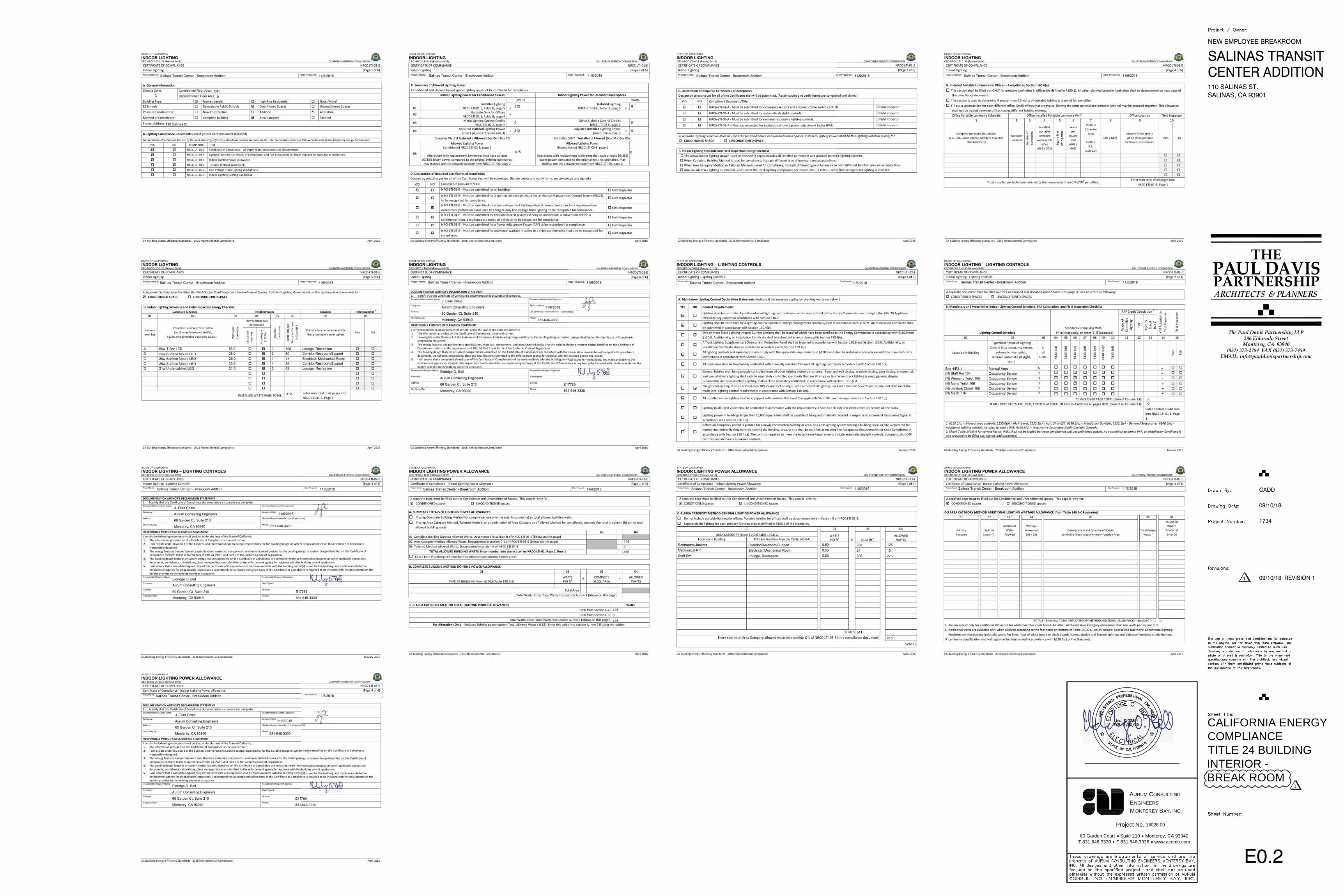
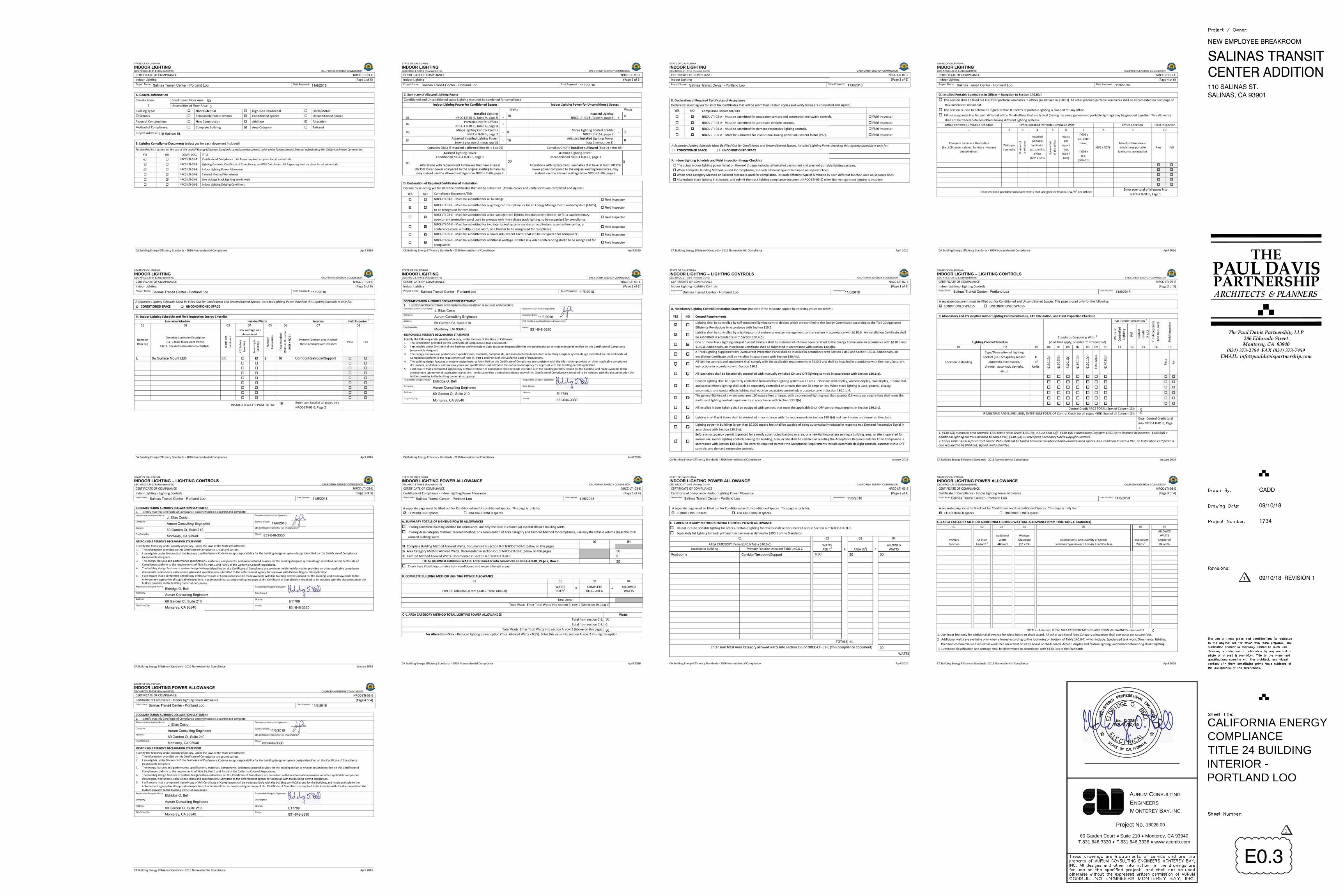
E0.2 CALIFORNIA ENERGY COMPLIANCETITLE 24 (BUILDING INTERIOR -BREAK ROOM) .
E0.3 CALIFORNIA ENERGY COMPLIANCETITLE 24 (BUILDING INTERIOR -PORTLAND LOO).
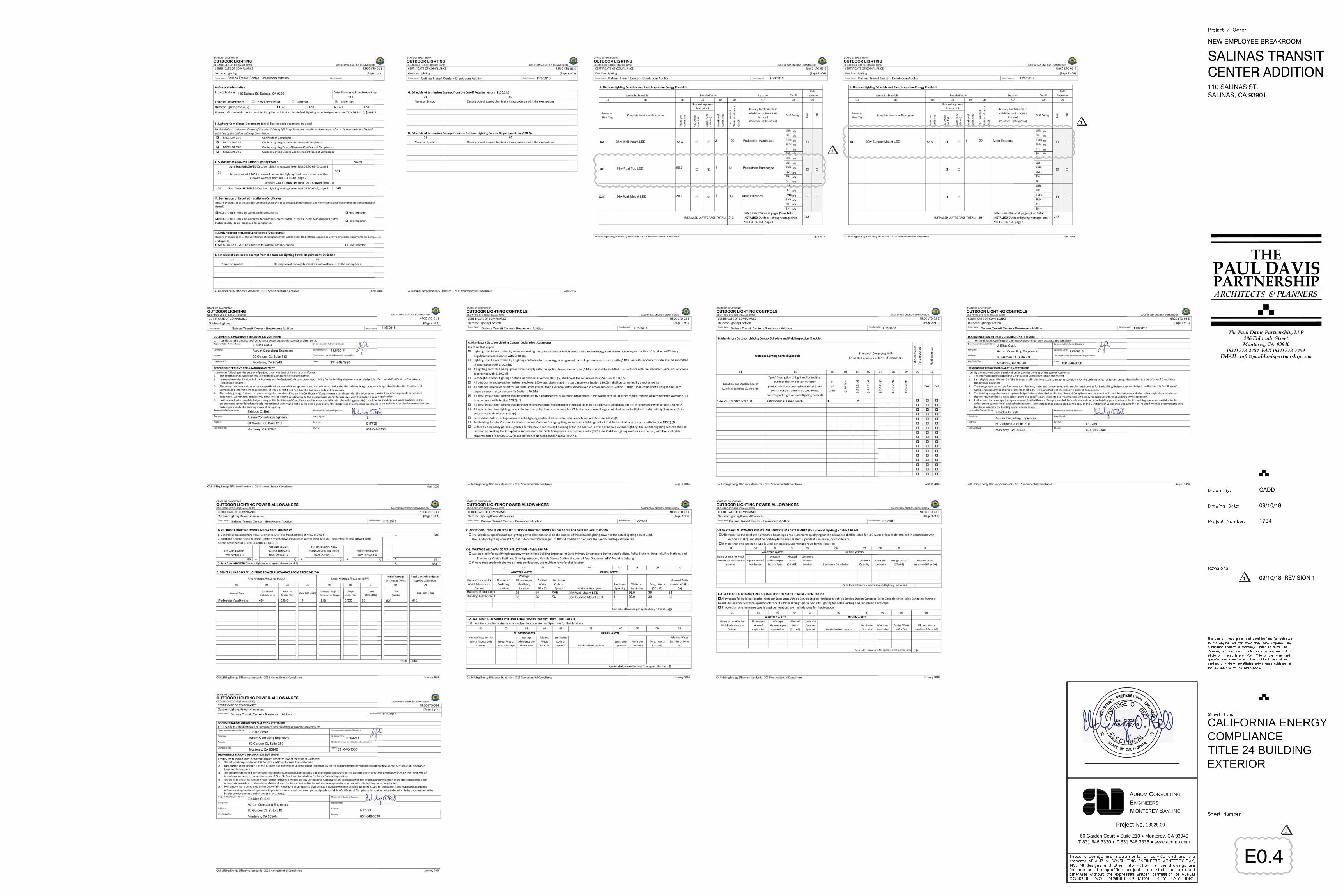
E0.4 CALIFORNIA ENERGY COMPLIANCETITLE 24 (BUILDING EXTERIOR).
E1.1 ELECTRICAL SINGLE LINE DIAGRAM,PANELBOARD SCHEDULE & DETAILS.
E2.1 ELECTRICAL DEMOLITION & NEWSITE PLANS.
E3.1 LIGHTING, POWER, SYSTEMS &PORTLAND LOO PLANS.
E5.1 ELECTRICAL DETAILS.
E6.1 ELECTRICAL SPECIFICATIONS.
APPLICABLE CODES & STANDARDSCODES:
1. 2016 CALIFORNIA ADMINISTRATIVE CODE C.C.R., TITLE 24, PART 1.
2. 2016 CALIFORNIA BUILDING CODE (CBC) C.C.R., TITLE 24, VOL. 1 & 2 BASED ONTHE 2015 INTERNATIONAL BUILDING CODE (IBC) WITH CALIFORNIAAMENDMENTS.
3. 2016 CALIFORNIA ELECTRICAL CODE (CEC) C.C.R., TITLE 24, PART 3 BASED ONTHE 2014 NATIONAL ELECTRICAL CODE (NEC) WITH CALIFORNIA AMENDMENTS.
4. 2016 CALIFORNIA MECHANICAL CODE (CMC) C.C.R., TITLE 24, PART 4 BASED ONTHE 2015 UNIFORM MECHANICAL CODE (UMC) WITH CALIFORNIA AMENDMENTS.
5. 2016 CALIFORNIA PLUMBING CODE (CPC) C.C.R., TITLE 24, PART 5 BASED ONTHE 2015 UNIFORM PLUMBING CODE (UPC) WITH CALIFORNIA AMENDMENTS.
6. 2016 CALIFORNIA ENERGY CODE C.C.R., TITLE 24, PART 6.
7. 2016 CALIFORNIA FIRE CODE (CFC) C.C.R., TITLE 24, PART 9 BASED ON THE 2015INTERNATIONAL FIRE CODE (IFC) WITH CALIFORNIA AMENDMENTS.
8. 2016 CALIFORNIA GREEN BUILDING STANDARDS CODE C.C.R., TITLE 24, PART 11.
9. 2016 CALIFORNIA REFERENCED STANDARDS CODE C.C.R., TITLE 24, PART 12.
10. TITLE 19 C.C.R., PUBLIC SAFETY, STATE FIRE MARSHAL REGULATIONS.
11. NATIONAL FIRE ALARM CODE (NFPA 72) 2016.
12. CITY OF SALINAS ORDINANCES, CODES, AND REGULATIONS.
STANDARDS:
1. AMERICAN NATIONAL STANDARDS INSTITUTE (ANSI)
2. ELECTRONICS INDUSTRIES ASSOCIATION (EIA)
3. INSTITUTE OF ELECTRICAL AND ELECTRONIC ENGINEERS (IEEE)
4. NATIONAL ELECTRICAL MANUFACTURERS ASSOCIATION (NEMA)
5. NATIONAL ELECTRICAL TESTING ASSOCIATION (NETA)
6. UNDERWRITER LABORATORIES (UL)
7. CALIFORNIA OCCUPATIONAL SAFETY AND HEALTH ACT STANDARDS (CAL/OSHA)
HALF SWITCHED DUPLEX RECEPTACLE
INSTALLATION
RECEPTACLE - DUPLEX
#10
E
2
3
FLOOR MOUNTED DUPLEX RECEPTACLE
J
PANELBOARD - FLUSH MOUNTED
SIZE PER CODE, TAPE AND TAG WIRES
PANELBOARD - SURFACE MOUNTED
EQUIPMENT PANEL - SURFACE MOUNTED
EQUIPMENT PANEL - FLUSH MOUNTED
METER W/ CURRENT TRANSFORMER
INTERIOR SPEAKERS CEILING MOUNTED
TV OUTLET
VOICE/DATA OUTLET - FLOOR MOUNTED
JUNCTION BOX - CEILING OR WALL MOUNTED,
GFCI CONVENIENCE RECEPTACLE - DUPLEX
DUPLEX RECEPTACLE MOUNTED ABOVE COUNTER -FIELD VERIFY HEIGHT
POWER OUTLET - SEE PLANS FOR NEMA TYPE
RECEPTACLE DOUBLE DUPLEX
VOICE/DATA WALL OUTLET
WALL TELEPHONE OUTLET
CLOCK +8'-0" AFF U.O.N. VERIFY BEFORE
PER EQUIPMENT MFGRS NAMEPLATE DATAFUSED DISCONNECT SWITCH ELEMENT FUSES SIZED
CONDUIT - UP
CONDUIT - DOWN
CONDUIT EMERGENCY SYSTEM
FLEX CONDUIT WITH CONNECTION
SURFACE METAL OR NON-METALLIC RACEWAY
CONDUIT - CONCEALED IN WALLS OR CEILING
CONDUIT - EXISTING
CONDUIT - BELOW SLAB OR UNDERGROUND: 3/4"MIN.
GROUND ELECTRODE
NEMA 3R ENCLOSURE UNLESS OTHERWISE SPECIFIEDMAGNETIC STARTER - NEMA SIZE INDICATED
NON-FUSED DISCONNECT SWITCH
GROUND ROD WITH GROUNDWELL BOX
CIRCUIT BREAKER
NORMALLY CLOSED CONTACT
NORMALLY OPEN CONTACT
TRANSFORMER - SEE SINGLE LINE FOR SIZE
MOTOR CONNECTION
COMBINATION STARTER/FUSED DISCONNECT SWITCH;
CONDUIT CONTINUATION
DETAIL OR SECTION REFERENCESECURITY DOOR CONTACTS
CAPPED OR STUB-OUT CONDUIT
PULLBOX
SYMBOLS & ABBREVIATIONS SHOWN ARE FOR GENERAL USE. DISREGARD THOSE WHICH DO NOT APPEAR ON THE PLANS.
DETAIL NOTE REFERENCE SYMBOLSEE ASSOCIATED NOTE ON SAME DETAIL2 1
E3.0
INTERIOR SPEAKERS WALL MOUNTED
M
LOW VOLTAGE WIRINGLV
INDICATES QUANTITY OF DATA OUTLETS
INDICATES QUANTITY OF TELEPHONE OUTLETS12
F301 FEEDER DESIGNATION;SEE ASSOCIATED NOTE ON SAME DETAIL
SHEET NOTE REFERENCE SYMBOL;SEE ASSOCIATED NOTE ON SAME SHEET
SCHEDULE SYMBOL; SEE ASSOCIATEDNOTE ON SAME SHEET
SINGLE RECEPTACLE
DUPLEX RECEPTACLE - CEILING MOUNTED
HEIGHTHTINTERCOM
PANELLIGHTING
KILOWATT
KILOVOLTJUNCTION BOX
LIGHTING CONTROL
KVA
LCP
LTG
JB
KW
KVKILOVOLT AMPERES
POWER POLE
FUSED DISCONNECT SWITCH; FUSED WITHDUAL-ELEMENT FUSES SIZED PER EQUIPMENTMFGR'S NAMEPLATE DATA
CCTV CAMERA
SECURITY MOTION DETECTOR
IC
INCANDESCENTINCAND
INTERMEDIATEIDF
FLOOR MOUNTED BOX
DETAIL NUMBER
SHEET NUMBER
DISTRIBUTION FRAME
ELECTRICAL SYMBOLS & ABBREVIATIONS
*
*
**
*
*
*
*
** +48" A.F.F. TO TOP OF BOX, U.O.N.+15" A.F.F. TO BOTTOM OF BOX, U.O.N.*
SECURITY SYSTEM KEYPAD
S
S
C
KP
SC
MD
GFCI CONVENIENCE DUPLEX RECEPTACLEMOUNTED ABOVE COUNTER - FIELD VERIFY HEIGHT
J
PULL BOXPBPA PUBLIC ADDRESS
CHLORIDEPOLYVINYL
REQUIRED
SHEET
SWITCH
PHASE
PANEL
PVC
PNL
REQD
SWBD
SHT
(R)
SW
PF
WITHWATT
VOLT
UON
XFMR
W/W
WP
V
TYP TYPICALMOUNTED
METAL HALIDE
THOUSANDLOW VOLTAGE
CIRCULAR MILS
MAIN LUGS ONLY
NEWNOT IN CONTRACT
ON CENTER
CONTRACTNOT IN ELECTRICAL
MOUNTING
POWER FACTOR
SWITCHBOARD
UNLESS OTHERWISE NOTED
REQUIREMENT(S)
RELOCATED
TRANSFORMERWEATHERPROOF
MTD
KCMLV
MHMLO
OC
NIECNIC(N)
MTG
OVERHEADOH
REQMT'S
MECHANICALMECH
RECPT'S RECEPTACLES(RP) REMOVABLE POLE
PWR POWER
UG UNDERGROUND
SINGLE LINE DIAGRAMSLD
OAH OVERALL HEIGHT
PASSIVE INFRAREDPIRPH
PHOTOVOLTAICPV
TTB TELEPHONE TERMINALBACKBOARD
MAIN DISTRIBUTION FRAMEMDF
MAIN POINT OF ENTRANCEMPOE
SYSTEMS TERMINATIONCABINET
STC
FUTURE
GROUND FAULT
GROUNDINTERRUPTING
GFCI
(F)
AFFA
ABOVE FINISHED FLOORAMPERE
GND, G
AWGARCH
BKR
CB
C.O.CLG
CTR
CKT
DIMDIST
CL
(E)
C
EQUIP
FIN
FACPFA
FL
EMT
FLOOR
METALLIC TUBING
CONTROL PANEL
EQUIPMENT
FIRE ALARM
FINISH
FIRE ALARM
AMERICAN WIRE
CIRCUIT BREAKER
BREAKERGAUGE
DISTRIBUTION
CIRCUITCENTER LINECEILINGCONDUIT ONLYCENTER
DIMENSION
EXISTING
ELECTRICAL
CONDUIT
ARCHITECT GALVANIZED RIGIDGRSSTEEL
EM EMERGENCY
ALUM/AL ALUMINUM
FLUOR FLUORESCENT
GENERAL CONTRACTORGC
CATV CABLE TV
CCTV CLOSED CIRCUIT TV
EC ELECTRICAL CONTRACTOR
GFI
(EL) EVENING LIGHT
NUMBER
NOT TO SCALENTS
NO.(NL) NIGHT LIGHT
NOMINALNOM
ABBREVIATIONS
D DIMMER
LETTER INDICATES DUPLEX HALFCONTROLLED RECEPTACLE
HC
*LETTER INDICATES DUPLEX FULLYCONTROLLED RECEPTACLE
C
*
SINGLE POLE SWITCH
FOUR WAY SWITCH
THREE WAY SWITCH
LIGHTING DIMMER
KEY OPERATED SWITCH
SINGLE POLE SWITCH,a = CIRCUIT CONTROLLED
MANUAL MOTOR STARTER
3
a
4
K
M
S WALL OCCUPANCY SENSOR
LIGHTING CONTROL OCCUPANCY SENSOR CORNER MOUNTED
DOUBLE SWITCHED WALL OCCUPANCYS 2 SENSOR **
**
****
**
**
****
S
S
S
S
S
S
S
DIMMER ROOM CONTROLLERDRC
DIGITAL DUAL TECHNOLOGYWALL OCC. SENSORS S
DIGITAL MULTI SCENELIGHTING SWITCHS
DIGITAL ON/OFF SWITCHS
S D DIGITAL DIMMER SWITCH
M#
PLUG LOAD CONTROLLER
ROOM LIGHTING CONTROLLER
LCP LIGHTING CONTROL PANEL
DIGITAL DAYLIGHT SENSORDL
DIGITAL DUAL TECHNOLOGYOCC. SENSOR
**
**
SEE SCHEDULE
SEE SCHEDULE
SEE SCHEDULE
EMERGENCY LIGHT
TRACK LIGHTING - SEE SCHEDULE
LUMINAIRE - RECESSED - SEE SCHEDULE
EXIT LIGHT - DIRECTIONAL ARROWS ASINDICATED - SEE SCHEDULE
LUMINAIRE - POLE OR POST MOUNTED -
BOLLARD OR PATH LIGHT - SEE SCHEDULE
STRIP FLUORESCENT OR LED LUMINAIRE -
LUMINAIRE - SURFACE MOUNTED -
LUMINAIRE - WALL MOUNTED SEE SCHEDULE
FLUORESCENT OR LED LUMINAIRE -
EMERGENCY OR NIGHT LIGHT
RECESSED WALL WASHER
SEE SCHEDULE
****
DIMMING DUAL TECHNOLOGY
**S
S 2
WALL SWITCH OCCUPANCY SENSOR
2-BUTTON DIMMING DUAL TECHNOLOGY WALL SWITCH OCCUPANCY SENSOR **
CH
DOOR BELL PUSHBUTTON
DOOR CHIME WITH LED
FC FOOT CANDLE
FLA FULL LOAD AMPS
MINIMUMMCACIRCUIT AMPS
MAXIMUM OVERMOCPCURRENT PROTECTION
RC
PC
**
WIRELESS ACCESS POINT (WAP) -CEILING MOUNTED
WIRELESS ACCESS POINT (WAP) -WALL MOUNTED - FIELD VERIFY HEIGHT
VOICE/DATA OUTLET MOUNTED ABOVECOUNTER - FIELD VERIFY HEIGHT
[#]
[#]
[#]CONDUIT - HOME RUN TO PANEL, TERMINALCABINET, ETC. RUNS MARKED WITHCROSSHATCHES INDICATE NUMBER OF #12AWG WIRES WHEN MORE THAN TWO. SIZECONDUIT ACCORDING TO SPECIFICATIONSAND APPLICABLE CODE. CROSS HATCHESWITH NUMBER ADJACENT INDICATES WIRESIZE OTHER THAN #12 AWG.
NUMBER IN BRACKETS DENOTES NUMBEROF CABLE DROPS WHEN MORE THAN (2).
[#]
SURFACE MOUNTED VOICE/DATA WALL OUTLET *SURFACE MOUNTED VOICE/DATA OUTLETMOUNTED ABOVE COUNTER - FIELD VERIFY HEIGHT
[#]
[#]
VOICE/DATA OUTLET - CEILING MOUNTED[#]
VOLTAGE DROPVD
EV ELECTRICAL VEHICLE
MAIN CIRCUIT BREAKER M.B.
TYPE DESCRIPTION MANUFACTURERLAMPS
LIGHT FIXTURE SCHEDULEFIXTURE NOTES:
1. ALL LED LIGHT FIXTURE DRIVERS SHALL BE ELECTRONIC TYPE, 10% TOTAL HARMONIC DISTORTIONMAXIMUM.
2. ALL LED LIGHT MODULES SHALL BE ENERGY SAVING 3500° K, 80 CRI MINIMUM, U.O.N. (SEESPECIFICATIONS FOR MORE INFORMATION).
3. ALL LED DRIVERS (AND ASSOC. FIXTS.) SHALL HAVE MANUFACTURER'S CERTIFICATION OF COMPLIANCEWITH CALIFORNIA ENERGY COMMISSION STANDARDS AND REQUIREMENTS, WHERE SUCH ARE USED INCONDITIONED SPACES.
4. EXIT SIGNS , EMERGENCY LIGHTS AND LIGHT FIXTURES WITH EMERGENCY BATTERY BACK-UP SHALLSUPPLY A MINIMUM DURATION OF 90 MINUTES OF POWER IN THE EVENT OF A POWER OUTAGE/FAILURE.
A 50 STATIC SERIES H.E. WILLIAMS
LED56W2'W x 4'L T-BAR LAY-IN LED LIGHT FIXTURE. FROSTED
ACRYLIC PRISMATIC LENS, WHITE FLAT STEEL DOORFRAME, 0-10V DIMMING, 120V. 3500°K
B 39 SERIESH.E. WILLIAMS
LED25W1'W x 4'L SURFACE MOUNT FIXTURE, FROSTED
RIBBED ACRYLIC SHIELDING. DIE-FORMED COLDROLLED-STEEL HOUSING. MATTE WHITE FINISH,120V.
3000°K
1
L LED8W24" SURFACE MOUNTED LED STRIP LIGHT, 4 WATTS
A FOOT. MOTION SENSOR CONTROLLLED. TO BEPROVIDED AND INSTALLED BY OTHERS.
XL LED30W10' SURFACE MOUNTED LED FLEXLIGHT
LIGHTROPE. 3 WATTS PER FOOT. PHOTO SENSORCONTROLLED . TO BE PROVIDED AND INSTALLEDBY OTHERS.
1
TYPE DESCRIPTION MANUFACTURERLAMPS
LIGHT FIXTURE SCHEDULEFIXTURE NOTES:
1. ALL LED LIGHT FIXTURE DRIVERS SHALL BE ELECTRONIC TYPE, 10% TOTAL HARMONIC DISTORTIONMAXIMUM.
2. ALL LED LIGHT MODULES SHALL BE ENERGY SAVING 3500° K, 80 CRI MINIMUM, U.O.N. (SEESPECIFICATIONS FOR MORE INFORMATION).
3. ALL LED DRIVERS (AND ASSOC. FIXTS.) SHALL HAVE MANUFACTURER'S CERTIFICATION OF COMPLIANCEWITH CALIFORNIA ENERGY COMMISSION STANDARDS AND REQUIREMENTS, WHERE SUCH ARE USED INCONDITIONED SPACES.
4. EXIT SIGNS , EMERGENCY LIGHTS AND LIGHT FIXTURES WITH EMERGENCY BATTERY BACK-UP SHALLSUPPLY A MINIMUM DURATION OF 90 MINUTES OF POWER IN THE EVENT OF A POWER OUTAGE/FAILURE.
C
XAVWPV SERIESH.E. WILLIAMS
LED36W14 3
4" W X 9 3 8"H X 6 5 8" DEEP WALL PACK FIXTURE.SOLITE DIFFUSED TEXTURED TEMPERED GLASSLENS. DIE-CAST ALUMINUM ENCLOSURE. SOLITEDIFFUSED TEXTURED TEMPERED GLASS LENS, BUGRATING B1-UO-G1. FACTORY-INSTALLED.BUTTON-STYLE PHOTOCELL. TFT DISTRIBUTIONTYPE. FINISH PER ARCHITECT. 0-10V DIMMINGDRIVER, 120V.
3000°K
XAE VWPV SERIESH.E. WILLIAMS
LED36WSAME AS TYPE "XA" EXCEPT WITH 10 WATT
EMERGENCY LED DRIVER.3000°K
D
LLMS SERIESWILLIAMS LIGHTING26W4' L SURFACE MOUNTED LED STRIP LIGHT FIXTURE. 20
GAUGE COLD ROLLED STEEL HOUSING, HIGHLYREFLECTIVE NON-GLARE MATTE WHITE REFLECTOR,FROSTED MATTE ACRYLIC SQUARE LENS, 0-10 DIMMINGDRIVER, 120V.
LED3500K
1SF-3-L18/835 SERIESH.E. WILLIAMS36" x 47
8" x 1" DEEP, SOLID FRONT UNDERCABINETLIGHT FIXTURE, FROSTED ACRYLIC #12 LENS,120V DRIVER
21WLED
3500K
XB L81-55W32LED4K-CDMGS50 SERIESHADCO
LED55W18.5" DIA x 33" HIGH TRADITIONAL POST TOP
MOUNTED LED FIXTURE, NEUTRAL WHITE LIGHT,BUG RATING B3-U2-G1, BLACK FINISH, TYPE VDISTRIBUTION, 50% SAFETY REDUCTION DIMMING,16' POLE.
4000°K291-16BLK4 SERIESPOLE:
1
1
INCLUDED WITHPRE-MANUFACTURED BUILDING
INCLUDED WITHPRE-MANUFACTURED BUILDING
1
1734
09/10/18
THPPARTNERSHIPAUL
The Paul Davis Partnership, LLP286 Eldorado StreetMonterey, CA 93940
(831) 373-2784 FAX (831) 373-7459EMAIL: [email protected]
NEW EMPLOYEE BREAKROOM
SALINAS TRANSIT
110 SALINAS ST.SALINAS, CA 93901
CADD
09/10/18 REVISION 11
60 Garden Court Suite 210 Monterey, CA 93940T.831.646.3330 F.831.646.3336 www.acemb.com
Project No.
ONTEREY
NGINEERS
ONSULTING
EM
URUMA C
AY, INC.B
18028.00
E0.2
CALIFORNIA ENERGYCOMPLIANCETITLE 24 BUILDINGINTERIOR -BREAK ROOM
1
1734
09/10/18
THPPARTNERSHIPAUL
The Paul Davis Partnership, LLP286 Eldorado StreetMonterey, CA 93940
(831) 373-2784 FAX (831) 373-7459EMAIL: [email protected]
NEW EMPLOYEE BREAKROOM
SALINAS TRANSIT
110 SALINAS ST.SALINAS, CA 93901
CADD
09/10/18 REVISION 11
60 Garden Court Suite 210 Monterey, CA 93940T.831.646.3330 F.831.646.3336 www.acemb.com
Project No.
ONTEREY
NGINEERS
ONSULTING
EM
URUMA C
AY, INC.B
18028.00
E0.3
CALIFORNIA ENERGYCOMPLIANCETITLE 24 BUILDINGINTERIOR -PORTLAND LOO
1
1734
09/10/18
THPPARTNERSHIPAUL
The Paul Davis Partnership, LLP286 Eldorado StreetMonterey, CA 93940
(831) 373-2784 FAX (831) 373-7459EMAIL: [email protected]
NEW EMPLOYEE BREAKROOM
SALINAS TRANSIT
110 SALINAS ST.SALINAS, CA 93901
CADD
09/10/18 REVISION 11
60 Garden Court Suite 210 Monterey, CA 93940T.831.646.3330 F.831.646.3336 www.acemb.com
Project No.
ONTEREY
NGINEERS
ONSULTING
EM
URUMA C
AY, INC.B
18028.00
E0.4
CALIFORNIA ENERGYCOMPLIANCETITLE 24 BUILDINGEXTERIOR
1
1
1

1734
09/10/18
THPPARTNERSHIPAUL
The Paul Davis Partnership, LLP286 Eldorado StreetMonterey, CA 93940
(831) 373-2784 FAX (831) 373-7459EMAIL: [email protected]
NEW EMPLOYEE BREAKROOM
SALINAS TRANSIT
110 SALINAS ST.SALINAS, CA 93901
CADD
09/10/18 REVISION 11
60 Garden Court Suite 210 Monterey, CA 93940T.831.646.3330 F.831.646.3336 www.acemb.com
Project No.
ONTEREY
NGINEERS
ONSULTING
EM
URUMA C
AY, INC.B
18028.00
E1.1
ELECTRICAL SINGLELINE DIAGRAM,PANELBOARDSCHEDULE & DETAILS
NO SCALE1 SINGLE LINE DIAGRAM
(DEMOLISH)
(EXISTING)
(NEW)
1. SEE 1/E3.1 FOR REQUIREMENTS.
2. REPLACE EXISTING 70A/2 POLE BREAKERWITH NEW BREAKER SHOWN. NEW BREAKERSHALL MATCH EXISTING IN TYPE AND AICRATING.
3. SEE 2/E2.1 AND 1/E3.1 FOR PULL BOX SIZEAND REQUIREMENTS.
DETAIL NOTES:
PANELBOARD SCHEDULE
M
200/2 M.B.
100/2
1 14" C., 3 #4 & 1 #8 GND
PANEL "B" BATHROOMPANEL
PANEL "A"
PORTLAND LOO
TO PG&E TRANSFORMER
FUTUREPORTLAND LOO
Voltage: 120/240V,1ø Bussing: 100AWire: 3W 1 2 PANEL B Feed: TOPType: NEMA 1 Mounting: FLUSHMains: M.L.O. A.I.C. 10,000
Load A B Bkr Ck ab Ck Bkr A B LoadRECEPTS - BREAK ROOM 900 20/1 1 2
30/22016 HP -1
GFCI RECEPT - WOMENS RESTROOM 180 20/1 3 4 2016 HP -1GFCI RECEPT - MENS RESTROOM 180 20/1 5 6 15/1 528 EF -1RECEPTS - REFRIGERATOR 900 20/1 7 8 20/1 180 ROOF MAINTENANCE RECEPTGFCI RECEPT - KITCHENETTE 1500 20/1 9 10
30/21500 WH - 1
GFCI RECEPT - KITCHENETTE 1500 20/1 11 12 1500 WH - 1(N) PORTLAND LOO 1400 20/1 13 14 15/1 48 RECEPT - CIRCULATION PUMPFUTURE PORTLAND LOO 1400 20/1 15 16 20/1 312 LIGHTS - INTERIORRECEPTS - JANITOR CLOSET 180 20/1 17 18 20/1 213 LIGHTS - EXTERIORSPARE 20/1 19 20 20/1 100 TIME CLOCKSPARE 20/1 21 22 20/1 SPARESPARE 20/1 23 24 20/1 SPARESPARE 20/1 25 26 20/1 SPARESPACE ONLY - 27 28 - SPACE ONLYSPACE ONLY - 29 30 - SPACE ONLY
4160 3980 4305 4108
1 SUBMITTAL SHALL MATCH EXACT BREAKER LOCATIONS SHOWN.
2 LABEL PANEL FOR SHORT CIRCUIT AMPS AVAILABLE PER CEC 110-24.
KVA Phase A 8.5 Total Load KVA 16.6KVA Phase B 8.1 Total Load Amperes 69
TYPICAL TRENCH SECTION2
NO SCALE
AC PAVING OR CONC.WHEN OCCURS
MIN. 95% COMPACT EARTH FILL, SEE SPECS
WARNING MARKER TAPECONTINUOUS LENGTH OFTRENCH
30"
12"
NOTES:
1. SAW CUT, TRENCH & BACKFILL FOR (N) CONDUITS. PATCH WALKWAY TO MATCH (E) SURROUNDING SURFACES. CARESHALL BE TAKEN TO PROTECT EXISTING TREES. RESEED OR RESOD (E) DISTURBED PLANTED AREAS TO ARCHITECT'SSATISFACTION.
2. EXISTING A.C. SHALL BE CUT AND REMOVED IN SUCH A MANNER SO AS NOT TO TEAR BULGE OR DISPLACE ADJACENTPAVEMENT. EDGES SHALL BE CLEAN AND VERTICAL. ALL CUTS SHALL BE PARALLEL OR PERPENDICULAR TO STREETCENTERLINE, WHEN PRACTICAL.
3. BASE MATERIAL TO BE REPLACED TO THE DEPTH OF EXISTING BASE AND COMPACTED TO A MIN. 95% RELATIVECOMPACTION. A.C. MAY BE SUBSTITUTED FOR BASE MATERIAL. WHEN USED AS BACKFILL, CLASS 100-E-100 P.C.C. MAYBE SUBSTITUTED FOR BASE MATERIAL.
4. A TACK COAT OF ASPHALTIC EMULSION OR PAVING ASPHALT SHALL BE APPLIED TO EXISTING A.C. AT ALL CONTACTSURFACES, PRIOR TO RESURFACING.
5. ASPHALTIC CONCRETE RESURFACING;A) MINIMUM TOTAL THICKNESS SHALL BE ONE INCH GREATER THAN EXISTING A.C.B) A.C. SHALL BE HOT PLANT MIX.
6. ALL A.C. RESURFACING SHALL BE SEAL COATED WITH AN EMULSIFIED ASPHALT AND COVERED WITH CLEAN SAND.
SAND BACKFILL[NATIVE SOIL]
CONDUIT, SEE PLANS FOR QUANTITY,SIZE AND USAGE
UNPAVED AREAS
6"
PAVED AREAS
6" CLASS 2 AGGREGATEBASE, 95% COMPACTION
3" THICK AC PAVINGWHEN OCCURS
SAW CUT (E) AC PAVINGWHEN OCCURS
GRADEFINISHED
NO SCALE
TYPICAL PULLBOX DETAIL3
30" MIN. U.O.N.
REINFORCED CONC. LID LABELED AS NOTED ON FINISHED GRADE
GROUT FILL (TYPICAL)
CONDUIT BELL ENDS
12"
6"
DRAWINGS
PULL BOX
PROVIDE EXTENSIONS ASREQUIRED
1 12" MIN. DIA.
DRAIN ROCK
8" MIN. ALL SIDES
NO SCALE
LINE
GROUND
WHITE
LOAD LOAD
NEUTRAL
120V/277V GROUND (SEEINSTALLATIONINSTRUCTIONS)
WATT STOPPER #DW-311 WITH#ASP-121 WALL PLATE
U.O.N. USE THE FOLLOWING SETTINGSTIME DELAY - 20 MINUTESLIGHT LEVEL HIGH-SENSITIVITY HIGH-MODE AUTOMATIC ON-----
FOR TECHNICAL SUPPORT CALL1-800-879-8585
OVERRIDE - NORMAL
4(WATT STOPPER #W1-200 WITH #ASP-121 WALL PLATE)
S D
LANDING LUGS
PG&E METER
TEST BYPASS
3
1
1
1
3
1
1
1
1
1
1
1
1
2
1
1 1
1
GROUND ROD BOX DETAIL
96" MIN.
18" MIN.
5
GENERAL NOTE:WHERE METAL CONDUIT USED INLIEU OF PVC, PROVIDE GROUNDBUSHINGS & BONDS PER CODE
NO SCALE
1. FINISHED GRADE
2. GROUND CONDUCTOR
3. SEAL CONDUIT WATERTIGHT
4. GROUT BOTTOM MINIMUM 3"
5. 34" x 10'-0" COPPER CLAD GROUND
ROD
6. LID LABELED "GROUND ROD"
7. CHRISTY "F8" GROUND ROD BOX
8. UNDISTURBED EARTH
9. GROUND CLAMP
10. COAT ALL INSIDE SURFACESW/SEALANT
DETAIL NOTES:
3
4
5
2
1 6
7
10
9
8
1
1734
09/10/18
THPPARTNERSHIPAUL
The Paul Davis Partnership, LLP286 Eldorado StreetMonterey, CA 93940
(831) 373-2784 FAX (831) 373-7459EMAIL: [email protected]
NEW EMPLOYEE BREAKROOM
SALINAS TRANSIT
110 SALINAS ST.SALINAS, CA 93901
CADD
09/10/18 REVISION 11
60 Garden Court Suite 210 Monterey, CA 93940T.831.646.3330 F.831.646.3336 www.acemb.com
Project No.
ONTEREY
NGINEERS
ONSULTING
EM
URUMA C
AY, INC.B
18028.00
E2.1
ELECTRICALDEMOLITION & NEWSITE PLANS
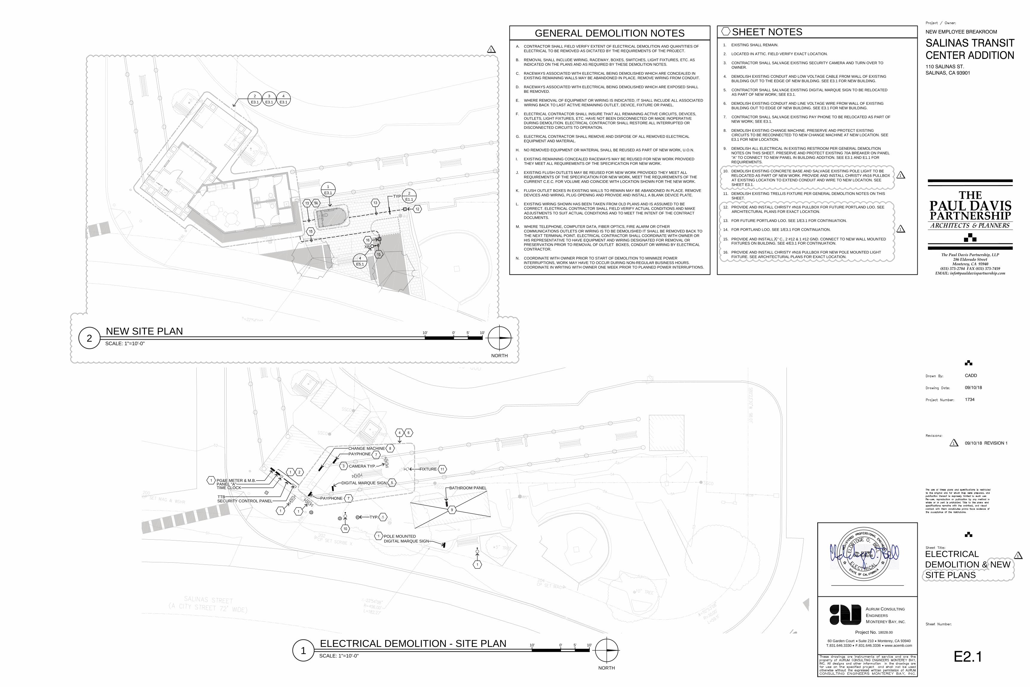
SHEET NOTES1. EXISTING SHALL REMAIN.
2. LOCATED IN ATTIC. FIELD VERIFY EXACT LOCATION.
3. CONTRACTOR SHALL SALVAGE EXISTING SECURITY CAMERA AND TURN OVER TOOWNER.
4. DEMOLISH EXISTING CONDUIT AND LOW VOLTAGE CABLE FROM WALL OF EXISTINGBUILDING OUT TO THE EDGE OF NEW BUILDING. SEE E3.1 FOR NEW BUILDING.
5. CONTRACTOR SHALL SALVAGE EXISTING DIGITAL MARQUE SIGN TO BE RELOCATEDAS PART OF NEW WORK; SEE E3.1.
6. DEMOLISH EXISTING CONDUIT AND LINE VOLTAGE WIRE FROM WALL OF EXISTINGBUILDING OUT TO EDGE OF NEW BUILDING. SEE E3.1 FOR NEW BUILDING.
7. CONTRACTOR SHALL SALVAGE EXISTING PAY PHONE TO BE RELOCATED AS PART OFNEW WORK; SEE E3.1.
8. DEMOLISH EXISTING CHANGE MACHINE. PRESERVE AND PROTECT EXISTINGCIRCUITS TO BE RECONNECTED TO NEW CHANGE MACHINE AT NEW LOCATION. SEEE3.1 FOR NEW LOCATION.
9. DEMOLISH ALL ELECTRICAL IN EXISTING RESTROOM PER GENERAL DEMOLITIONNOTES ON THIS SHEET. PRESERVE AND PROTECT EXISTING 70A BREAKER ON PANEL"A" TO CONNECT TO NEW PANEL IN BUILDING ADDITION. SEE E3.1 AND E1.1 FORREQUIREMENTS.
10. DEMOLISH EXISTING CONCRETE BASE AND SALVAGE EXISTING POLE LIGHT TO BERELOCATED AS PART OF NEW WORK. PROVIDE AND INSTALL CHRISTY #N16 PULLBOXAT EXISTING LOCATION TO EXTEND CONDUIT AND WIRE TO NEW LOCATION. SEESHEET E3.1.
11. DEMOLISH EXISTING TRELLIS FIXTURE PER GENERAL DEMOLITION NOTES ON THISSHEET.
12. PROVIDE AND INSTALL CHRISTY #N16 PULLBOX FOR FUTURE PORTLAND LOO. SEEARCHITECTURAL PLANS FOR EXACT LOCATION.
13. FOR FUTURE PORTLAND LOO. SEE 1/E3.1 FOR CONTINUATION.
14. FOR PORTLAND LOO. SEE 1/E3.1 FOR CONTINUATION.
15. PROVIDE AND INSTALL 12" C., 2 #12 & 1 #12 GND. CONNECT TO NEW WALL MOUNTEDFIXTURES ON BUILDING. SEE 4/E3.1 FOR CONTINUATION.
16. PROVIDE AND INSTALL CHRISTY #N16 PULLBOX FOR NEW POLE MOUNTED LIGHTFIXTURE. SEE ARCHITECTURAL PLANS FOR EXACT LOCATION.
GENERAL DEMOLITION NOTESA. CONTRACTOR SHALL FIELD VERIFY EXTENT OF ELECTRICAL DEMOLITION AND QUANTITIES OF
ELECTRICAL TO BE REMOVED AS DICTATED BY THE REQUIREMENTS OF THE PROJECT.
B. REMOVAL SHALL INCLUDE WIRING, RACEWAY, BOXES, SWITCHES, LIGHT FIXTURES, ETC. ASINDICATED ON THE PLANS AND AS REQUIRED BY THESE DEMOLITION NOTES.
C. RACEWAYS ASSOCIATED WITH ELECTRICAL BEING DEMOLISHED WHICH ARE CONCEALED INEXISTING REMAINING WALLS MAY BE ABANDONED IN PLACE. REMOVE WIRING FROM CONDUIT.
D. RACEWAYS ASSOCIATED WITH ELECTRICAL BEING DEMOLISHED WHICH ARE EXPOSED SHALLBE REMOVED.
E. WHERE REMOVAL OF EQUIPMENT OR WIRING IS INDICATED, IT SHALL INCLUDE ALL ASSOCIATEDWIRING BACK TO LAST ACTIVE REMAINING OUTLET, DEVICE, FIXTURE OR PANEL.
F. ELECTRICAL CONTRACTOR SHALL INSURE THAT ALL REMAINING ACTIVE CIRCUITS, DEVICES,OUTLETS, LIGHT FIXTURES, ETC. HAVE NOT BEEN DISCONNECTED OR MADE INOPERATIVEDURING DEMOLITION. ELECTRICAL CONTRACTOR SHALL RESTORE ALL INTERRUPTED ORDISCONNECTED CIRCUITS TO OPERATION.
G. ELECTRICAL CONTRACTOR SHALL REMOVE AND DISPOSE OF ALL REMOVED ELECTRICALEQUIPMENT AND MATERIAL.
H. NO REMOVED EQUIPMENT OR MATERIAL SHALL BE REUSED AS PART OF NEW WORK, U.O.N.
I. EXISTING REMAINING CONCEALED RACEWAYS MAY BE REUSED FOR NEW WORK PROVIDEDTHEY MEET ALL REQUIREMENTS OF THE SPECIFICATION FOR NEW WORK.
J. EXISTING FLUSH OUTLETS MAY BE REUSED FOR NEW WORK PROVIDED THEY MEET ALLREQUIREMENTS OF THE SPECIFICATION FOR NEW WORK, MEET THE REQUIREMENTS OF THECURRENT C.E.C. FOR VOLUME AND COINCIDE WITH LOCATION SHOWN FOR THE NEW WORK.
K. FLUSH OUTLET BOXES IN EXISTING WALLS TO REMAIN MAY BE ABANDONED IN PLACE. REMOVEDEVICES AND WIRING, PLUG OPENING AND PROVIDE AND INSTALL A BLANK DEVICE PLATE.
L. EXISTING WIRING SHOWN HAS BEEN TAKEN FROM OLD PLANS AND IS ASSUMED TO BECORRECT. ELECTRICAL CONTRACTOR SHALL FIELD VERIFY ACTUAL CONDITIONS AND MAKEADJUSTMENTS TO SUIT ACTUAL CONDITIONS AND TO MEET THE INTENT OF THE CONTRACTDOCUMENTS.
M. WHERE TELEPHONE, COMPUTER DATA, FIBER OPTICS, FIRE ALARM OR OTHERCOMMUNICATIONS OUTLETS OR WIRING IS TO BE DEMOLISHED IT SHALL BE REMOVED BACK TOTHE NEXT TERMINAL POINT. ELECTRICAL CONTRACTOR SHALL COORDINATE WITH OWNER ORHIS REPRESENTATIVE TO HAVE EQUIPMENT AND WIRING DESIGNATED FOR REMOVAL ORPRESERVATION PRIOR TO REMOVAL OF OUTLET BOXES, CONDUIT OR WIRING BY ELECTRICALCONTRACTOR.
N. COORDINATE WITH OWNER PRIOR TO START OF DEMOLITION TO MINIMIZE POWERINTERRUPTIONS, WORK MAY HAVE TO OCCUR DURING NON-REGULAR BUSINESS HOURS.COORDINATE IN WRITING WITH OWNER ONE WEEK PRIOR TO PLANNED POWER INTERRUPTIONS.
1ELECTRICAL DEMOLITION - SITE PLANSCALE: 1"=10'-0"
NORTH
10' 5'0' 10'
2NEW SITE PLANSCALE: 1"=10'-0"
NORTH
10' 5'0' 10'
1
1
1
1
CHANGE MACHINE
PG&E METER & M.B.
PAYPHONE
PAYPHONE
SC
CAMERA TYP.
SC
POLE MOUNTEDDIGITAL MARQUE SIGN
BATHROOM PANEL
FIXTURE
PANEL "A"TIME CLOCK
TTBSECURITY CONTROL PANEL
DIGITAL MARQUE SIGN
TYP.
2E3.1
3E3.1
4E3.1
1E3.1
XB
TYP2
E1.1
4E5.1
1734
09/10/18
THPPARTNERSHIPAUL
The Paul Davis Partnership, LLP286 Eldorado StreetMonterey, CA 93940
(831) 373-2784 FAX (831) 373-7459EMAIL: [email protected]
NEW EMPLOYEE BREAKROOM
SALINAS TRANSIT
110 SALINAS ST.SALINAS, CA 93901
CADD
09/10/18 REVISION 11
60 Garden Court Suite 210 Monterey, CA 93940T.831.646.3330 F.831.646.3336 www.acemb.com
Project No.
ONTEREY
NGINEERS
ONSULTING
EM
URUMA C
AY, INC.B
18028.00
E3.1
LIGHTING,POWER,SYSTEMS &PORTLAND LOO PLAN
SCALE: 1/2"=1'-0"
2' 1'0' 2'
NORTH
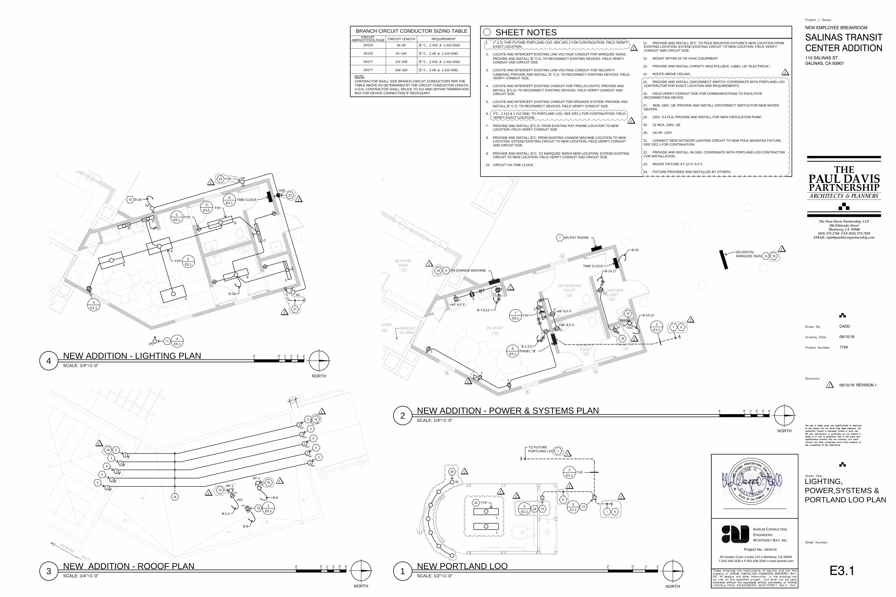
SHEET NOTES1. 2" C.O. FOR FUTURE PORTLAND LOO, SEE 2/E2.1 FOR CONTINUATION. FIELD VERIFY
EXACT LOCATION.
2. LOCATE AND INTERCEPT EXISTING LINE VOLTAGE CONDUIT FOR MARQUEE SIGNS.PROVIDE AND INSTALL 3 4" C.O. TO RECONNECT EXISTING DEVICES. FIELD VERIFYCONDUIT AND CIRCUIT SIZE.
3. LOCATE AND INTERCEPT EXISTING LOW VOLTAGE CONDUIT FOR SECURITYCAMERAS. PROVIDE AND INSTALL 3 4" C.O. TO RECONNECT EXISTING DEVICES. FIELDVERIFY CONDUIT SIZE.
4. LOCATE AND INTERCEPT EXISTING CONDUIT FOR TRELLIS LIGHTS. PROVIDE ANDINSTALL 1
2"C.O. TO RECONNECT EXISTING DEVICES. FIELD VERIFY CONDUIT ANDCIRCUIT SIZE.
5. LOCATE AND INTERCEPT EXISTING CONDUIT FOR SPEAKER SYSTEM. PROVIDE ANDINSTALL 1
2" C.O. TO RECONNECT DEVICES. FIELD VERIFY CONDUIT SIZE.
6. 2"C., 2 #12 & 1 #12 GND. TO PORTLAND LOO. SEE 2/E2.1 FOR CONTINUATION. FIELDVERIFY EXACT LOCATION.
7. PROVIDE AND INSTALL 12"C.O. FROM EXISTING PAY PHONE LOCATION TO NEWLOCATION. FIELD VERIFY CONDUIT SIZE.
8. PROVIDE AND INSTALL 12"C. FROM EXISTING CHANGE MACHINE LOCATION TO NEWLOCATION. EXTEND EXISTING CIRCUIT TO NEW LOCATION. FIELD VERIFY CONDUITAND CIRCUIT SIZE.
9. PROVIDE AND INSTALL 3 4"C. TO MARQUEE SIGN'S NEW LOCATION. EXTEND EXISTINGCIRCUIT TO NEW LOCATION. FIELD VERIFY CONDUIT AND CIRCUIT SIZE.
10. CIRCUIT VIA TIME CLOCK.
11. PROVIDE AND INSTALL 3 4"C. TO POLE MOUNTED FIXTURE'S NEW LOCATION FROMEXISTING LOCATION. EXTEND EXISTING CIRCUIT TO NEW LOCATION. FIELD VERIFYCONDUIT AND CIRCUIT SIZE.
12. MOUNT WITHIN 25' OF HVAC EQUIPMENT.
13. PROVIDE AND INSTALL CHRISTY #N16 PULLBOX. LABEL LID "ELECTRICAL".
14. ROUTE ABOVE CEILING.
15. PROVIDE AND INSTALL DISCONNECT SWITCH. COORDINATE WITH PORTLAND LOOCONTRACTOR FOR EXACT LOCATION AND REQUIREMENTS.
16. FIELD VERIFY CONDUIT SIZE FOR COMMUNICATIONS TO FACILITATERECONNECTING DEVICE.
17. 3KW, 240V, 1Ø, PROVIDE AND INSTALL DISCONNECT SWITCH FOR NEW WATERHEATER.
18. 120V, 0.4 FLA; PROVIDE AND INSTALL FOR NEW CIRCULATION PUMP.
19. 21 MCA, 240V, 1Ø.
20. 1/6 HP, 120V.
21. CONNECT NEW OUTDOOR LIGHTING CIRCUIT TO NEW POLE MOUNTED FIXTURE.SEE 2/E2.1 FOR CONTINUATION.
22. PROVIDE AND INSTALL #6 GND. COORDINATE WITH PORTLAND LOO CONTRACTORFOR INSTALLATION.
23. MOUNT FIXTURE AT 12'-0" A.F.F.
24. FIXTURE PROVIDED AND INSTALLED BY OTHERS.
1 NEW PORTLAND LOO
SCALE: 1/4"=1'-0"
NORTH
2 NEW ADDITION - POWER & SYSTEMS PLAN 4' 0' 1' 2' 3' 4'
SCALE: 1/4"=1'-0"
NORTH
4 NEW ADDITION - LIGHTING PLAN 4' 0' 1' 2' 3' 4'
SCALE: 1/4"=1'-0"
NORTH
3 NEW ADDITION - ROOOF PLAN 4' 0' 1' 2' 3' 4'
CIRCUIT LENGTH
20/120
BRANCH CIRCUIT CONDUCTOR SIZING TABLECIRCUIT
56'-90'
20/120 91'-140'
20/277 131'-205'
20/277 206'-330'
REQUIREMENT
NOTE:CONTRACTOR SHALL SIZE BRANCH CIRCUIT CONDUCTORS PER THETABLE ABOVE AS DETERMINED BY THE CIRCUIT CONDUCTOR LENGTH,U.O.N. CONTRACTOR SHALL SPLICE TO #12 AWG WITHIN TERMINATIONBOX FOR DEVICE CONNECTION IF NECESSARY.
AMPACITY/VOLTAGE1
2" C., 2 #10 & 1 #10 GND.
12" C., 2 #8 & 1 #10 GND.
12" C., 2 #10 & 1 #10 GND.
12" C., 2 #8 & 1 #10 GND.
1
1
1
(N) STAFFSTAFF
(N) MEN'STOILET
(N) WOMEN'STOILET (N) JANITOR'S
CLOSET
(N) MECH
(E) WORKAREA
REMOVE(E) SINK
A
A
A
A
102
103104
105
106
108
107
+44" A.F.F.
+48" A.F.F.
+48" A.F.F.B-7,9,11
(R) CHANGE MACHINE
(R) PAY PHONE
(R) DIGITALMARQUEE SIGN
7 911
1
1
1
1
B-1,3,5
1 3
5
PANEL "B"6
E5.1
7E5.1
TIME CLOCK
B-20
B-14,17
17
142
E1.1
TYP.
1
1
1
1
1
1
#10
B-10,12WH-1
3E1.1
TO FUTUREPORTLAND LOO
TYP.2
E1.1
1
1 1
5E1.1
1XL
L
L
TYP.
1
1
XA
XA
XAE
XA
S
S
S
S
A
A
A
B
B
C
C
S
D
D
B-18
B-16
(R)
TYP.2
E5.1
3E5.1
TYP. 5E5.1
4E5.1
9E5.1
TYP.
TIME CLOCK
S
4E1.1
1
TYP.
1
1
(N) BL
(E) BLDG
12"
MIN
WP
WP
HP-1 WP
EF-1
J
J
J
J
J
J
J
J
J
J
B-2,4
B-8
B-6
1E5.1
WP
WP
WP
WP
WP
#10
1
1
1
1
1734
09/10/18
THPPARTNERSHIPAUL
The Paul Davis Partnership, LLP286 Eldorado StreetMonterey, CA 93940
(831) 373-2784 FAX (831) 373-7459EMAIL: [email protected]
NEW EMPLOYEE BREAKROOM
SALINAS TRANSIT
110 SALINAS ST.SALINAS, CA 93901
CADD
09/10/18 REVISION 11
60 Garden Court Suite 210 Monterey, CA 93940T.831.646.3330 F.831.646.3336 www.acemb.com
Project No.
ONTEREY
NGINEERS
ONSULTING
EM
URUMA C
AY, INC.B
18028.00
E5.1
ELECTRICAL DETAILS
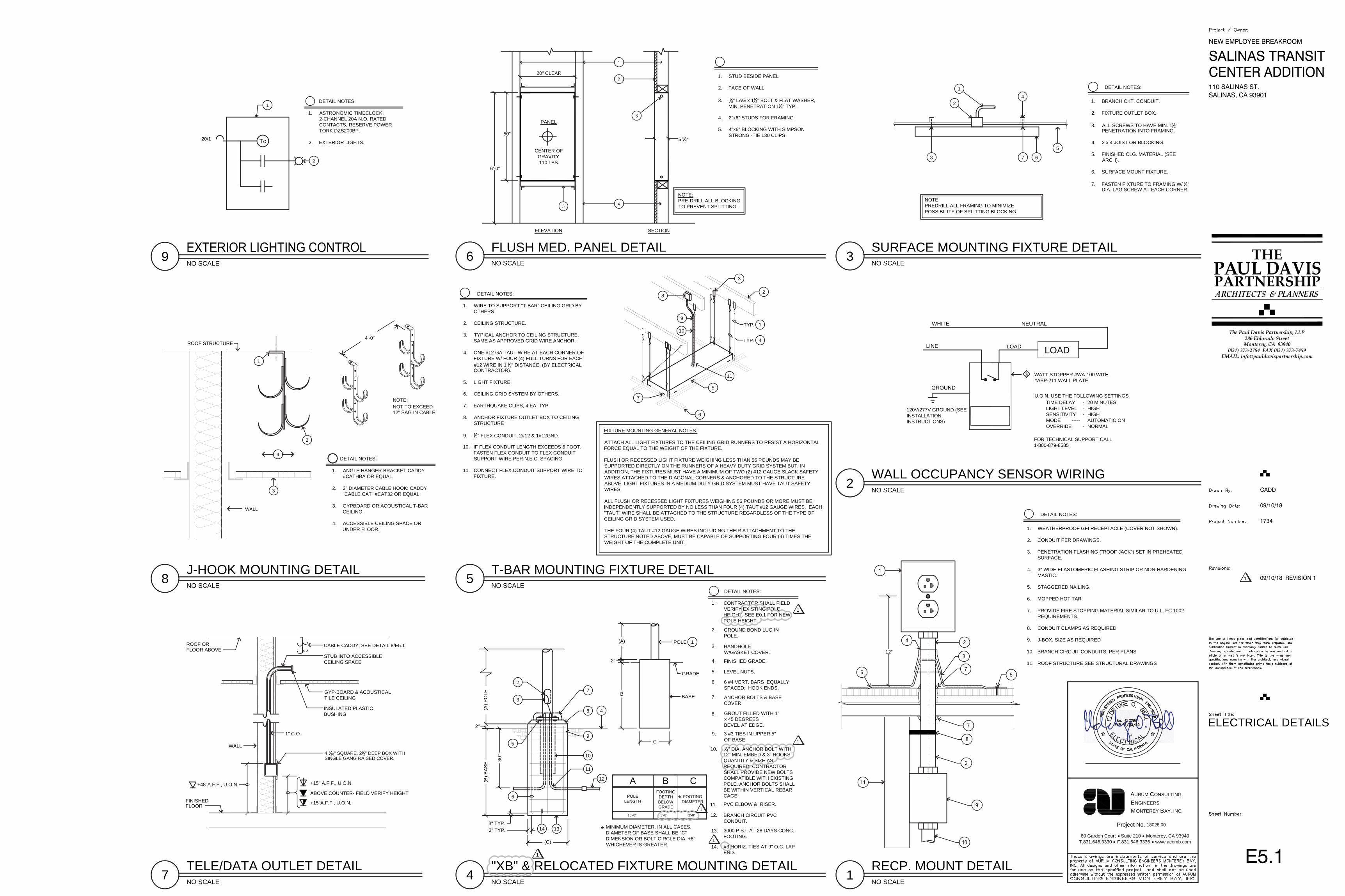
RECP. MOUNT DETAILNO SCALE
1
1. WEATHERPROOF GFI RECEPTACLE (COVER NOT SHOWN).
2. CONDUIT PER DRAWINGS.
3. PENETRATION FLASHING ("ROOF JACK") SET IN PREHEATEDSURFACE.
4. 3" WIDE ELASTOMERIC FLASHING STRIP OR NON-HARDENINGMASTIC.
5. STAGGERED NAILING.
6. MOPPED HOT TAR.
7. PROVIDE FIRE STOPPING MATERIAL SIMILAR TO U.L. FC 1002REQUIREMENTS.
8. CONDUIT CLAMPS AS REQUIRED
9. J-BOX, SIZE AS REQUIRED
10. BRANCH CIRCUIT CONDUITS, PER PLANS
11. ROOF STRUCTURE SEE STRUCTURAL DRAWINGS
DETAIL NOTES:
12"
WALL OCCUPANCY SENSOR WIRINGNO SCALE
2
SURFACE MOUNTING FIXTURE DETAILNO SCALE
3
T-BAR MOUNTING FIXTURE DETAILNO SCALE
5
FLUSH MED. PANEL DETAILNO SCALE
6
LINE
GROUND
WHITE
LOAD LOAD
NEUTRAL
120V/277V GROUND (SEEINSTALLATIONINSTRUCTIONS)
WATT STOPPER #WA-100 WITH#ASP-211 WALL PLATE
U.O.N. USE THE FOLLOWING SETTINGSTIME DELAY - 20 MINUTESLIGHT LEVEL HIGH-SENSITIVITY HIGH-MODE AUTOMATIC ON-----
FOR TECHNICAL SUPPORT CALL1-800-879-8585
OVERRIDE - NORMAL
S
NOTE:PREDRILL ALL FRAMING TO MINIMIZEPOSSIBILITY OF SPLITTING BLOCKING
1. BRANCH CKT. CONDUIT.
2. FIXTURE OUTLET BOX.
3. ALL SCREWS TO HAVE MIN. 112"
PENETRATION INTO FRAMING.
4. 2 x 4 JOIST OR BLOCKING.
5. FINISHED CLG. MATERIAL (SEEARCH).
6. SURFACE MOUNT FIXTURE.
7. FASTEN FIXTURE TO FRAMING W/ 14"DIA. LAG SCREW AT EACH CORNER.
DETAIL NOTES:
41
2
5
673
6
10
7
9
8
5
11
4
TYP.
2
1
3
DETAIL NOTES:
1. WIRE TO SUPPORT "T-BAR" CEILING GRID BYOTHERS.
2. CEILING STRUCTURE.
3. TYPICAL ANCHOR TO CEILING STRUCTURE,SAME AS APPROVED GRID WIRE ANCHOR.
4. ONE #12 GA TAUT WIRE AT EACH CORNER OFFIXTURE W/ FOUR (4) FULL TURNS FOR EACH#12 WIRE IN 1 12" DISTANCE. (BY ELECTRICALCONTRACTOR).
5. LIGHT FIXTURE.
6. CEILING GRID SYSTEM BY OTHERS.
7. EARTHQUAKE CLIPS, 4 EA. TYP.
8. ANCHOR FIXTURE OUTLET BOX TO CEILINGSTRUCTURE
9. 12" FLEX CONDUIT, 2#12 & 1#12GND.
10. IF FLEX CONDUIT LENGTH EXCEEDS 6 FOOT,FASTEN FLEX CONDUIT TO FLEX CONDUITSUPPORT WIRE PER N.E.C. SPACING.
11. CONNECT FLEX CONDUIT SUPPORT WIRE TOFIXTURE.
FIXTURE MOUNTING GENERAL NOTES:
ATTACH ALL LIGHT FIXTURES TO THE CEILING GRID RUNNERS TO RESIST A HORIZONTALFORCE EQUAL TO THE WEIGHT OF THE FIXTURE.
FLUSH OR RECESSED LIGHT FIXTURE WEIGHING LESS THAN 56 POUNDS MAY BESUPPORTED DIRECTLY ON THE RUNNERS OF A HEAVY DUTY GRID SYSTEM BUT, INADDITION, THE FIXTURES MUST HAVE A MINIMUM OF TWO (2) #12 GAUGE SLACK SAFETYWIRES ATTACHED TO THE DIAGONAL CORNERS & ANCHORED TO THE STRUCTUREABOVE. LIGHT FIXTURES IN A MEDIUM DUTY GRID SYSTEM MUST HAVE TAUT SAFETYWIRES.
ALL FLUSH OR RECESSED LIGHT FIXTURES WEIGHING 56 POUNDS OR MORE MUST BEINDEPENDENTLY SUPPORTED BY NO LESS THAN FOUR (4) TAUT #12 GAUGE WIRES. EACH"TAUT" WIRE SHALL BE ATTACHED TO THE STRUCTURE REGARDLESS OF THE TYPE OFCEILING GRID SYSTEM USED.
THE FOUR (4) TAUT #12 GAUGE WIRES INCLUDING THEIR ATTACHMENT TO THESTRUCTURE NOTED ABOVE, MUST BE CAPABLE OF SUPPORTING FOUR (4) TIMES THEWEIGHT OF THE COMPLETE UNIT.
TYP.
1. STUD BESIDE PANEL
2. FACE OF WALL
3. 38" LAG x 11
2" BOLT & FLAT WASHER,MIN. PENETRATION 11
4" TYP.
4. 2"x6" STUDS FOR FRAMING
5. 4"x6" BLOCKING WITH SIMPSONSTRONG -TIE L30 CLIPS
6'-0"
50"
20" CLEAR
5 34"
PANEL
CENTER OF GRAVITY 110 LBS.
A B CFOOTING
DEPTHBELOWGRADE
FOOTINGDIAMETER
POLELENGTH
15'-0" 3'-6" 2'-0"
B
(A)
C
MINIMUM DIAMETER. IN ALL CASES,DIAMETER OF BASE SHALL BE "C"DIMENSION OR BOLT CIRCLE DIA. +8"WHICHEVER IS GREATER.
*
*
POLE
BASE
GRADE
2"
GROUND BOND LUG INPOLE.
HANDHOLEW/GASKET COVER.
FINISHED GRADE.
LEVEL NUTS.
6 #4 VERT. BARS EQUALLYSPACED; HOOK ENDS.
ANCHOR BOLTS & BASECOVER.
GROUT FILLED WITH 1"x 45 DEGREESBEVEL AT EDGE.
3 #3 TIES IN UPPER 5"OF BASE.3
4" DIA. ANCHOR BOLT WITH12" MIN. EMBED & 3" HOOKS;QUANTITY & SIZE ASREQUIRED. CONTRACTORSHALL PROVIDE NEW BOLTSCOMPATIBLE WITH EXISTINGPOLE. ANCHOR BOLTS SHALLBE WITHIN VERTICAL REBARCAGE.
PVC ELBOW & RISER.
BRANCH CIRCUIT PVCCONDUIT.
3000 P.S.I. AT 28 DAYS CONC.FOOTING.
12.
11.
10.
9.
8.
7.
6.
5.
4.
3.
2.
1.
14.
13.3" TYP.3" TYP.
(C)#3 HORIZ. TIES AT 9" O.C. LAPEND.
(B) B
AS
E 30"
2"
(A) P
OLE
1314
12
11
10
9
8
7
6
5
4
3
2
DETAIL NOTES:
1
CONTRACTOR SHALL FIELDVERIFY EXISTING POLEHEIGHT. SEE E0.1 FOR NEWPOLE HEIGHT.
"XB" & RELOCATED FIXTURE MOUNTING DETAILNO SCALE
4
NOTE:PRE-DRILL ALL BLOCKINGTO PREVENT SPLITTING.
ELEVATION SECTION
12" SAG IN CABLE.NOT TO EXCEEDNOTE:
4'-0"
J-HOOK MOUNTING DETAILNO SCALE
8
WALL
1. ANGLE HANGER BRACKET CADDY#CATHBA OR EQUAL.
2. 2" DIAMETER CABLE HOOK: CADDY"CABLE CAT" #CAT32 OR EQUAL.
3. GYPBOARD OR ACOUSTICAL T-BARCEILING.
4. ACCESSIBLE CEILING SPACE ORUNDER FLOOR.
1
2
3
4DETAIL NOTES:
TELE/DATA OUTLET DETAILNO SCALE
7
+15"A.F.F., U.O.N.
CABLE CADDY; SEE DETAIL 8/E5.1FLOOR ABOVE
FINISHED
ROOF OR
1" C.O.
GYP-BOARD & ACOUSTICALTILE CEILING
STUB INTO ACCESSIBLECEILING SPACE
INSULATED PLASTICBUSHING
WALL
FLOOR
41116" SQUARE, 21
2" DEEP BOX WITHSINGLE GANG RAISED COVER.
+48"A.F.F., U.O.N.
ABOVE COUNTER- FIELD VERIFY HEIGHT
NO SCALE9
20/1 Tc
1
2
DETAIL NOTES:
1. ASTRONOMIC TIMECLOCK,2-CHANNEL 20A N.O. RATEDCONTACTS, RESERVE POWERTORK DZS200BP.
2. EXTERIOR LIGHTS.
+15" A.F.F., U.O.N.
1
1
1
1
1
ROOF STRUCTURE

1734
09/10/18
THPPARTNERSHIPAUL
The Paul Davis Partnership, LLP286 Eldorado StreetMonterey, CA 93940
(831) 373-2784 FAX (831) 373-7459EMAIL: [email protected]
NEW EMPLOYEE BREAKROOM
SALINAS TRANSIT
110 SALINAS ST.SALINAS, CA 93901
CADD
09/10/18 REVISION 11
60 Garden Court Suite 210 Monterey, CA 93940T.831.646.3330 F.831.646.3336 www.acemb.com
Project No.
ONTEREY
NGINEERS
ONSULTING
EM
URUMA C
AY, INC.B
18028.00
E6.1
ELECTRICALSPECIFICATIONS
SECTION 26 05 00
GENERAL ELECTRICAL REQUIREMENTS
PART 1 - GENERAL
1.01 Description of Work:A. Furnish and install all required in-place equipment, conduits, conductors, cables and any
miscellaneous materials for the satisfactory interconnection and operation of all associated electricalsystems.
1.02 Submittals:A. As specified in Division 1. Submit to the Architect shop drawings, manufacturer's data and
certificates for equipment, materials and finish, and pertinent details for each system specified.Information to be submitted includes manufacturer's descriptive literature of cataloged products,equipment, drawings, diagrams, performance and characteristic curves as applicable, test data andcatalog cuts. Obtain written approval before procurement, fabrication, or delivery of the items tothe job site.
B. Proposed substitutions of products will not be reviewed or approved prior to awarding of theContract.
C. Substitutions shall be proven to the Architect or Engineer to be equal or superior to the specifiedproduct. Architect's decision is final. The Contractor shall pay all costs incurred by the Architectand Engineer in reviewing and processing any proposed substitutions whether or not a proposedsubstitution is accepted.
D. If a proposed substitution is rejected, the contractor shall furnish the specified product at noincrease in contract price.
E. If a proposed substitution is accepted, the contractor shall be completely responsible for alldimensional changes, electrical changes, or changes to other work which are a result of thesubstitution. The accepted substitution shall be made at no additional cost to the owner or designconsultants.
1.03 Quality Assurance:A. Codes: All electrical equipment and materials, including installation and testing, shall conform to
the latest editions of the following applicable codes:1. California Electrical Code (CEC).2. Occupational Safety and Health Act (OSHA) standards.3. All applicable local codes, rules and regulations.4. Electrical Contractor shall posses a C-10 license and all other licenses as may be required.
Licenses shall be in effect at start of this contract and be maintained throughout the duration ofthis contract.
B. Variances: In instances where two or more codes are at variance, the most restrictive requirementshall apply.
C. Standards: Equipment shall conform to applicable standards of American National StandardsInstitute (ANSI), Electronics Industries Association (EIA), Institute of Electrical and ElectronicsEngineers (IEEE), and National Electrical Manufacturers Association (NEMA).
D. Underwriter Laboratories (UL) listing is required for all equipment and materials where such listingis offered by the Underwriters Laboratories. Provide service entrance labels for all equipmentrequired by the NEC to have such labels.
E. The electrical contractor shall guarantee all work and materials installed under this contract for aperiod of one (1) year from date of acceptance by owner.
F. All work and materials covered by this specification shall be subject to inspection at any and alltimes by representatives of the owner. Work shall not be closed in or covered before inspection andapproval by the owner or his representative. Any material found not conforming with thesespecifications shall, within 3 days after being notified by the owner, be removed from premises; ifsaid material has been installed, entire expense of removing and replacing same, including anycutting and patching that may be necessary, shall be borne by the contractor.
1.04 Contract Documents: A. Drawings: The Electrical Drawings shall govern the general layout of the completed construction.
1. Locations of equipment, panels, pullboxes, conduits, stub-ups, ground connections areapproximate unless dimensioned; verify locations with the Architect prior to installation.
2. The general arrangement and location of existing conduits, piping, apparatus, etc., is approximate.The drawings and specifications are for the assistance and guidance of the contractor, exactlocations, distances and elevations are governed by actual field conditions. Accuracy of datagiven herein and on the drawings is not guaranteed. Minor changes may be necessary toaccommodate work. The contractor is responsible for verifying existing conditions. Should it benecessary to deviate from the design due to interference with existing conditions or work inprogress, claims for additional compensation shall be limited to those for work required byunforeseen conditions as determined by the Architect.
3. All drawings and divisions of these specifications shall be considered as whole. The contractorshall report any apparent discrepancies to the Architect prior to submitting bids.
4. The contractor shall be held responsible to have examined the site and compared it with thespecifications and plans and to have satisfied himself as to the conditions under which the work isto be performed. He shall be held responsible for knowledge of all existing conditions whether ornot accurately described. No subsequent allowance shall be made for any extra expense due tofailure to make such examination.
1.05 Closeout Submittals:A. Manuals: Furnish manuals for equipment where manuals are specified in the equipment
specifications or are specified in Division 1.
1.06 Coordination:A. Coordinate the electrical work with the other trades, code authorities, utilities and the Architect.B. Contractor shall pay all inspection and other applicable fees and procure all permits necessary for
the completion of this work.C. Where connections must be made to existing installations, properly schedule all the required work,
including the power shutdown periods.D. When two trades join together in an area, make certain that no electrical work is omitted.
1.07 Job Conditions:A. Operations: Perform all work in compliance with Division 1
1. Keep the number and duration of power shutdown periods to a minimum.2. Show all proposed shutdowns and their expected duration on the construction schedule. Schedule
and carry out shutdowns so as to cause the least disruption to operation of the Owner's facilities.3. Carry out shutdown only after the schedule has been approved, in writing, by the owner. Submit
power interruption schedule 15 days prior to date of interruption.B. Construction Power: Unless otherwise noted in Division 1 of these specifications, contractor shall
make all arrangements and provide all necessary facilities for temporary construction power fromthe owner's on site source. Energy costs shall be paid for by the Owner.
1.08 Safety and Indemnity:A. The Contractor is solely and completely responsible for conditions of the job site including safety
of all persons and property during performance of the work. This requirement will applycontinually and not be limited to normal working hours. The contractor shall provide and maintainthroughout the work site proper safeguards including, but not limited to, enclosures, barriers,warning signs, lights, etc. to prevent accidental injury to people or damage to property.
B. The Contractor performing work under this Division of the Specifications shall hold harmless,indemnify, and defend the Owner, the Engineer, their consultants, and each of their officers, agentsand employees from any and all liability claims, losses, or damage arising out of or alleged to arisefrom bodily injury, sickness, or death of a person or persons and for all damages arising out ofinjury to or destruction of property arising directly or indirectly out of or in connection with theperformance of the work under this Division of the Specifications, and from the Contractor'snegligence in the performance of the work described in the construction contract documents, butnot including liability that may be due to the sole negligence of the Owner, the Engineer, theirConsultants or their officers, agents and employees.
C. If a work area is encountered that contains hazardous materials, the contractor is advised tocoordinate with the owner and it's abatement consultant for abatement of hazardous material by theOwner's Representative. "Hazardous materials" means any toxic substance regulated or controlledby OSHA, EPA, State of California or local rules, regulations and laws. Nothing herein shall beconstrued to create a liability for Aurum Consulting Engineers regarding hazardous materialsabatement measures, or discovery of hazardous materials.
1.09 Access Doors:A. The contractor shall install access panels as required where floors, walls or ceilings must be
penetrated for access to electrical, control, fire alarm or other specified electrical devices. Theminimum size panel shall be 14" x 14" in usable opening. Where access by a service person isrequired, minimum usable opening shall be 18" x 24".
1.10 Arc Flash:A. The contractor shall install a clearly visible arc flash warning to the inside door of all panelboards
and industrial control panels, as well as to the front of all switchboards and motor control centersthat are a part of this project.
B. The warning shall have the following wording: line 1 "WARNING" (in large letters), line 2"Potential Arc Flash Hazard" (in medium letters), line 3 & 4 "Appropriate Personal ProtectiveEquipment and Tools required when working on this equipment".
1.11 All boxes and enclosures for emergency circuits shall be permanently marked with a readily visiblered spray painted mark.
PART 2 - PRODUCTS
2.01 Nameplates:A. Identify each piece of equipment and related controls with a rigid laminated engraved plastic
nameplate. Unless otherwise noted, nameplates shall be melamine plastic 0.125 inch thick, whitewith black center core. Surface shall be matte finish. Corners shall be square. Accurately alignlettering and engrave into the core. Minimum size of nameplates shall be 0.5 by 2.5 inches unlessotherwise noted. Where not otherwise specified, lettering shall be a minimum of 0.25 inch highnormal block style. Engrave nameplates with the inscriptions indicated on the Drawings and, if notso indicated, with the equipment name. Securely fasten nameplates in place using two stainlesssteel or brass screws.
2.02 Finish requirements:A. Equipment: Refer to each electrical equipment section of these Specifications for painting
requirements of equipment enclosures. Repair any final paint finish which has been damaged or isotherwise unsatisfactory, to the satisfaction of the Architect.
B. Wiring System: In finished areas, paint all exposed conduits, boxes and fittings to match the colorof the surface to which they are affixed.
PART 3 - EXECUTION
3.01 Workmanship:A. All electrical equipment and materials shall be installed in a neat and workmanship manner in
accordance with the "NECA-1 Standard Practices For Good Workmanship in ElectricalContracting". Workmanship of the entire job shall be first class in every respect.
3.02 Equipment Installations:A. Provide the required inserts, bolts and anchors, and securely attach all equipment and materials to
their supports.B. Do all the cutting and patching necessary for the proper installation work and repair any damage
done.C. Earthquake restraints: all electrical equipment, including conduits over 2 inches in diameter, shall
be braced or anchored to resist a horizontal force acting in any direction as per Title 24, part 2, table16a-o, part 3.
D. Structural work: All core drilling, bolt anchor insertion, or cutting of existing structural concreteshall be approved by a California registered structural consulting engineer prior to the execution ofany construction. At all floor slabs and structural concrete walls to be drilled, cut or bolt anchorsinserted, the contractor shall find and mark all reinforcing in both faces located by means of x-ray,pach-ometer, or prof-ometer. Submit sketch showing location of rebar and proposed cuts, cores, orbolt anchor locations for approval.
3.03 Field Test:A. Perform equipment field tests and adjustments. Properly calibrate, adjust and operationally check
all circuits and components, and demonstrate as ready for service.B. Operational Tests: Operationally test all circuits to demonstrate that the circuits and equipment
have been properly installed and adjusted and are ready for full-time service. Demonstrate theproper functioning of circuits in all modes of operation, including alarm conditions.
3.04 Records:A. Maintain one copy of the contract Drawing Sheets on the site of the work for recording the "as
built" condition. After completion of the work, the Contractor shall carefully mark the work asactually constructed, revising, deleting and adding to the Drawing Sheets as required. As builtDrawings shall be delivered to the Architect within ten (10) days of completion of construction.
3.05 Clean Up:A. Upon completion of electrical work, remove all surplus materials, rubbish, and debris that
accumulated during the construction work. Leave the entire area neat, clean, and acceptable to theArchitect.
3.06 Mechanical and Plumbing Electrical Work:A. The requirements for electrical power and/or devices for all mechanical and plumbing equipment
supplied and/or installed under this Contract shall be coordinated and verified with the following:1. Mechanical and Plumbing Drawings.2. Mechanical and Plumbing sections of these Specifications.3. Manufacturers of the Mechanical and Plumbing equipment supplied.
B. The coordination and verification shall include the voltage, ampacity, phase, location and type ofdisconnect, control, and connection required. Any changes that are required as a result of thiscoordination and verification shall be a part of this Contract.
C. The Electrical Contractor shall furnish and install the following for all mechanical and plumbingequipment:
1. Line voltage conduit and wiring.2. Disconnect switches.3. Manual line motor starters.
D. Automatic line voltage controls and magnetic starters shall be furnished by the Mechanical and/orPlumbing Contractor and installed and connected by the Electrical Contractor. When subcontractedfor by the Mechanical and/or Plumbing Contractor, all line voltage control wiring installed by theElectrical Contractor shall be done per directions from the Mechanical and/or Plumbing Contractor.
E. All low voltage control wiring for Mechanical and Plumbing equipment shall be installed inconduit. Furnishing, installation and connection of all low voltage conduit, boxes, wiring andcontrols shall be by the Mechanical and/or Plumbing Contractor.
F. Manual motor starters, where required, shall have toggle type operators with pilot light and meltingalloy type overload relays, SQUARE D COMPANY, Class 2510, Type FG-1P (surface) or TypeFS-1P (flush) or ITE, WESTINGHOUSE or GENERAL ELECTRIC equal.
SECTION 26 05 26
GROUNDING
PART 1 - EXECUTION
1.1 Grounding and Bonding:A. Grounding and bonding shall be as required by codes and local authorities.B. All electrical equipment shall be grounded, including, but not limited to, panel boards, terminal
cabinets and outlet boxes.C. The ground pole of receptacles shall be connected to their outlet boxes by means of a copper ground
wire connecting to a screw in the back of the box.D. A green insulated copper ground wire, sized to comply with codes, shall be installed in all conduit
runs.E. All metal parts of pull boxes shall be grounded per code requirements.F. All ground conductors shall be green insulated copper.
SECTION 26 05 42
CONDUITS, RACEWAYS AND FITTINGS
PART 1 - EXECUTION
1.01 Conduit, Raceway and Fitting Installation:A. For conduit runs exposed to weather provide rigid metal (GRS).B. For conduit run underground, in concrete or masonry block wall and under concrete slabs, install
minimum ¾" size nonmetallic (PVC) with PVC elbows. Where conduits transition fromunderground or under slab to above grade install wrapped rigid metal (GRS) elbows and risers.
C. For conduit runs concealed in steel or wood framed walls or in ceiling spaces or exposed in interiorspaces above six feet over the finished floor, install EMT.
D. Flexible metal conduit shall be used only for the connection of recessed lighting fixtures and motorconnections unless otherwise noted on the Drawings. Liquid-tight steel flexible conduit shall beused for motor connections.
E. The minimum size raceway shall be 1/2-inch unless indicted otherwise on the Drawings.F. Installation shall comply with the CEC.G. From pull point to pull point, the sum of the angles of all of the bends and offset shall not exceed
360 degrees.H. Conduit Supports: Properly support all conduits as required by the NEC. Run all conduits
concealed except where otherwise shown on the drawings.1. Exposed Conduits: Support exposed conduits within three feet of any equipment or device and at
intervals not exceeding NEC requirements; wherever possible, group conduits together andsupport on common supports. Support exposed conduits fastened to the surface of the concretestructure by one-hole clamps, or with channels. Use conduit spacers with one-hole clamps.
a. Conduits attached to walls or columns shall be as unobtrusive as possible and shall avoid windows.Run all exposed conduits parallel or at right angles to building lines.b. Group exposed conduits together. Arrange such conduits uniformly and neatly.
2. Support all conduits within three feet of any junction box, coupling, bend or fixture.3. Support conduit risers in shafts with Unistrut Superstrut, or approved equal, channels and straps.
I. Moisture Seals: Provide in accordance with NEC paragraphs 230-8 and 300-5(g).J. Where PVC conduit transitions from underground to above grade, provide rigid steel 90's with
risers. Rigid steel shall be half-lap wrapped with 20 mil tape and extend minimum 12" above grade.K. Provide a nylon pull cord in each empty raceway.L. Provide galvanized rigid steel factory fittings for galvanized rigid steel conduit.M. Slope all underground raceways to provide drainage; for example, slope conduit from equipment
located inside a building to the pull box or manhole located outside the building.N. Conduits shall be blown out and swabbed prior to pulling wires.
SECTION 26 05 19
LINE VOLTAGE WIRE AND CABLE
PART 1 - PRODUCTS
1.01 Conductors:A. Conductors shall be copper, type THHN/THWN/MTW oil and gasoline resistant, 600 volt rated
insulation.B. Conductors shall be stranded copper.C. Minimum power and control wire size shall be No. 12 AWG unless otherwise noted.D. All conductors used on this Project shall be of the same type and conductor material.
1.02 Terminations:A. Manufacturer - Terminals as manufactured by T&B, Burndy or equal.B. Wire Terminations - Stranded conductors shall be terminated in clamping type terminations which
serve to contain all the strands of the conductor. Curling of a stranded conductor around a screwtype terminal is not allowed. For screw type terminations, use a fork type stake-on termination onthe stranded conductor. Use only a stake-on tool approved for the fork terminals selected.
C. End Seals - Heat shrink plastic caps of proper size for the wire on which used.
1.03 Tape:A. Tape used for terminations and cable marking shall be compatible with the insulation and jacket of
the cable and shall be of plastic material.
PART 2 - EXECUTION
2.01 Cable Installation:A. Clean Raceways - Clean all raceways prior to installation of cables as specified in Section 26 05 42
- Conduits Raceway and Fittings.B. All wiring including low voltage wiring shall be installed in conduit, U.O.N.C. All feeder conductors shall be continuous from equipment to equipment. Splices in feeders are not
permitted unless specifically noted or approved by the Electrical Engineer.D. All branch circuit wiring shall be run concealed in ceiling spaces, walls, below floors or in crawl
spaces unless noted otherwise.
2.02 Cable Terminations and Splices:A. Splices - UL Listed wirenuts.B. Terminations - Shall comply with the following:
1. Make up and form cable and orient terminals to minimize cable strain and stress on device beingterminated on.
2. Burnish oxide from conductor prior to inserting in oxide breaking compound filled terminal.
2.03 Circuit and Conductor Identification:A. Color Coding - Provide color coding for all circuit conductors. Insulation color shall be white for
neutrals and green for grounding conductors. Conductor colors shall be as follows:VOLTAGE 240/120VPhase A BlackPhase B RedNeutral WhiteGround Green
B. Color coding shall be in the conductor insulation for all conductors #10 AWG and smaller; forlarger conductors, color shall be either in the insulation or in colored plastic tape applied at everylocation where the conductor is readily accessible.
C. Circuit Identification - All underground distribution and service circuits shall be provided withplastic identification tags in each secondary box and at each termination. Tags shall identify thesource transformer of the circuit and the building number(s) serviced by the circuit.
2.04 Field Tests:A. All systems shall test free from short circuits and grounds, shall be free from mechanical and
electrical defects, and shall show an insulation resistance between phase conductors and ground ofnot less than the requirements of the CEC. All circuits shall be tested for proper neutral connections.
SECTION 26 05 33
OUTLET, JUNCTION AND PULL BOXES
PART 1 - PRODUCTS
1.01 Outlet boxes, Junction and Pull boxesA. Standard Outlet Boxes: Galvanized, steel, knock-out type of size and configuration best suited to
the application indicated on the Drawings. Minimum box size shall be 4 inches square (octagon formost light fixtures) by 1-1/2 inches deep with mud rings as required. Boxes used with conduit 1" orlarger shall be minimum 2" deep.
B. Switch boxes: Minimum box size shall be 4 inches square by 1-1/2 inches deep with mud rings asrequired. Install multiple switches in standard gang boxes with raised device covers suitable for theapplication indicated.
C. Conduit bodies: Cadmium plated, cast iron alloy. Conduit bodies with threaded conduit hubs andneoprene gasketed, cast iron covers. Bodies shall be used to facilitate pulling of conductors or tomake changes in conduit direction only. Splices are not permitted in conduit bodies. Crouse-HindsForm 8 Condulets, Appleton Form 35 Unilets or equal.
D. Sheet Metal Boxes: Use standard outlet or concrete ring boxes wherever possible; otherwise use aminimum 16 gauge galvanized sheet metal, NEMA I box sized to Code requirements with coverssecured by cadmium plated machine screws located six inches on centers. Circle AW Products,Hoffman Engineering Company or equal.
E. Flush Mounted Pull boxes and Junction boxes: Provide overlapping covers with flush head coverretaining screws, prime coated.
PART 2 - EXECUTION
2.01 Outlet BoxesA. General:
1. All outlet boxes shall finish flush with building walls, ceilings and floors except in mechanicaland electrical rooms above accessible ceiling or where exposed work is called for on theDrawings.
2. Install raised device covers (plaster rings) on all switch and receptacle outlet boxes installed inmasonry or stud walls or in furred, suspended or exposed concrete ceilings. Covers shall be of adepth to suit the wall or ceiling finish.
3. Leave no unused openings in any box. Install close-up plugs as required to seal openings.B. Box Layout:
1. Outlet boxes shall be installed at the locations and elevations shown on the drawings or specifiedherein. Make adjustments to locations as required by structural conditions and to suitcoordination requirements of other trades.
2. Locate switch outlet boxes on the latch side of doorways.3. Outlet boxes shall not be installed back to back nor shall through-wall boxes be permitted. Outlet
boxes on opposite sides of a common wall shall be separated horizontally by at least one stud orvertical structural member.
4. For outlets mounted above counters, benches or backsplashes, coordinate location and mountingheights with built-in units. Adjust mounting height to agree with required location for equipmentserved.
5. On fire rated walls, the total face area of the outlet boxes shall not exceed 100 square inches per100 square feet of wall area.
C. Supports:1. Outlet Boxes installed in metal stud walls shall be equipped with brackets designed for attaching
directly to the studs or shall be mounted on specified box supports.2. Fixture outlet boxes installed in suspended ceiling of gypsum board or lath and plaster
construction shall be mounted to 16 gauge metal channel bars attached to main ceiling runners.3. Fixture outlet boxes installed in suspended ceilings supporting acoustical tiles or panels shall be
supported directly from the structure above where pendant mounted lighting fixture are to beinstalled on the box.
4. Fixture Boxes above tile ceilings having exposed suspension systems shall be supported directlyfrom the structure above.
5. Outlet and / or junction boxes shall not be supported by grid or fixture hanger wires at anylocations.
2.02 Junction And Pull BoxesA. General:
1. Install junction or pull boxes where required to limit bends in conduit runs to not more than 360degrees or where pulling tension achieved would exceed the maximum allowable for the cable tobe installed. Note that these boxes are not shown on the Drawings.
2. Locate pull boxes and junction boxes in concealed locations above accessible ceilings or exposedin electrical rooms, utility rooms or storage areas.
3. Install raised covers (plaster rings) on boxes in stud walls or in furred, suspended or exposedconcrete ceilings. Covers shall be of a depth to suit the wall or ceiling finish.
4. Leave no unused openings in any box. Install close-up plugs as required to seal openings.5. Identify circuit numbers and panel on cover of junction box with black marker pen.
B. Box Layouts:1. Boxes above hung ceilings having concealed suspension systems shall be located adjacent to
openings for removable recessed lighting fixtures.C. Supports:
1. Boxes installed in metal stud walls shall be equipped with brackets designed for attaching directlyto the studs or shall be mounted on specified box supports.
2. Boxes installed in suspended ceilings of gypsum board or lath and plaster construction shall bemounted to 16 gauge metal channel bars attached to main ceiling runners.
3. Boxes installed in suspended ceilings supporting acoustical tiles or panels shall be supporteddirectly from the structure above.
4. Boxes mounted above suspended acoustical tile ceilings having exposed suspension systems shallbe supported directly from the structure above.
SECTION 26 27 26
DEVICES WIRING
PART 1 - PRODUCTS
1.01 Receptacles:A. General - Receptacles shall be heavy duty, high abuse, grounding type.B. Duplex Receptacles:
1. Receptacles shall be specification grade, rated 20 ampere, two-pole, 3-wire, 120 volt, NEMA 5-20configuration, self-grounding with screw terminals. Color shall be as selected by the Architect.
2. Devices shall have a nylon face, back and side wired.3. Manufacturer: Hubbell #DR20 Series, Leviton #5825 Series.
C. GFCI Receptacles:1. Device shall be rated 20 ampere, 2-pole, 3-wire, 120 volt, conforming to NEMA 5-20
configuration. Face shall be nylon composition. Unit shall have an LED type red indicator light,test and reset push buttons. Color shall be as selected by the Architect.
2. GFCI component shall meet UL 943 Class A standards with a tripping time of 1/40 second at 5milliamperes current unbalance. Operating range shall extend from -31°F to 158°F. Unit shallhave transient voltage protection and shall be ceramic encapsulated for protection againstmoisture.
3. Manufacturer: Hubbell #GF20_ _LA Series, Leviton #7899 Series.
1.02 Switches:A. Switches shall be rated 20 amperes to 120/277 volts ac. Units shall be flush mounted,
self-grounding, quiet operating toggle devices. Handle color shall be as selected by the Architect.5. Manufacturer: Hubbell #HBL1221 Series, Leviton #1221 Series
B. Timed switches: Shall be as designed by Paragon Electric Company # ET2000f or Watt StopperTS-200 rated for the voltage specified on drawings. Time out shall be adjustable from 5 minutes upto 12 hours. Unit shall be provided with warning alarm.
1.03 Plates:A. General - Plates shall be of the style and color to match the wiring devices, and of the required
number of gangs. Plates shall conform with NEMA WD 1 , UL 514 and FS W-P-455A. Plates onfinished walls shall be non-metallic or stainless steel. Plates on unfinished walls and on fittingsshall be of zinc plated steel or case metal and shall have rounded corners and beveled edges.
B. Non-Metallic: Plates shall be plain with beveled edges and shall be nylon or reinforced fiberglass.C. Stainless Steel: Plates shall be .040 inches thick with beveled edges and shall be manufactured
from No. 430 alloy having a brushed or satin finish.D. Cast Metal: Plates shall be cast or malleable iron covers with gaskets so as to be moisture resistant
or weatherproof.E. Blank Plates: Cover plates for future telephone outlets shall match adjacent device wall plates in
appearance and construction.
PART 2 - EXECUTION
2.01 Installation of Wiring Devices:A. Interior Locations: In finished walls, install each device in a flush mounted box with washers as
required to bring the device mounting strap level with the surface of the finished wall. Onunfinished walls, surface mount boxes level and plumb.
B. Mounting Heights: Adjust boxes so that the front edge of the box shall not be farther back from thefinished wall plane than 1/4-inch. Adjust boxes so that they do not project beyond the finishedwall. Height of device shall be as follows:
1. Receptacles 15 Inches from finished floor to bottom of box unless otherwise noted on thedrawings.
2. Toggle Switches 48 Inches from finished floor to top of boxC. Receptacles:
1. Ground each receptacle using a grounding conductor, not a yoke or screw contact.2. Install receptacles with connections spliced to the branch circuit wiring in such a way that
removal of the receptacle will not disrupt neutral continuity and branch circuit power will not belost to other receptacles in the same circuit.
2.02 Installation of Wall Plates:A. General - Plates shall match the style of the device and shall be plumb within 1/16-inch of the
vertical or horizontal.B. Interior Locations, Finished Walls: Install non-metallic plates so that all four edges are in
continuous contact with the finished wall surfaces. Plaster filling will not be permitted. Do not useoversized plates or sectional plates.
C. Interior Locations, Unfinished Walls: Install stainless steel or cast metal cover plates.D. Exterior Locations: Install cast metal plates with gaskets on wiring devices in such a manner as to
provide a rain tight weatherproof installation. Cover type shall match box type. Cover shall be[Lockable] outdoor "in-use" type.
E. Future Locations: Install blank cover plates on all unused outlets.F. Labeling: All switch and receptacle plates shall be labeled on the top portion of the plate with the
panelboard and circuit number serving that device. Lettering shall be 116" minimum high, blackcolor, on clear Mylar tape.
2.03 Tests:A. Receptacles:
1. After installation of receptacles, energize circuits and test each receptacle to detect lack of groundcontinuity, reversed polarity, and open neutral condition.
SECTION 26 24 16
PANELBOARDS
PART 1 - PRODUCTS
1.01 Panelboards:A. General: Lighting and Receptacle Panelboards shall be the automatic circuit breaker type. The
number and arrangement of circuits, trip ratings, spares and blank spaces for future circuit breakersshall be as shown on the Drawings or, if not shown, 42 circuits. All circuit breakers shall bequick-make, quick-break, thermal-magnetic, bolt-on type (unless otherwise noted on drawings ),with 1, 2 or 3 poles as shown, each with a single operating handle. Tandem or piggy-back breakersshall not be used.
B. Nameplates:1. Each panelboard shall have a field mounted identifying, rigid, plastic nameplate giving the panel
identification as shown on the Drawings.2. Each panelboard shall have a manufacturer's nameplate showing the voltage, bus rating, number
of phases, frequency and number of wires.C. Construction:
1. Door and trim shall be finished to match finish type and color of surrounding wall. Box shall behot-dip galvanized, field finished to match the front.
2. Panelboards and enclosures shall conform to requirements of all relevant codes. Panelboards shallbe suitable for use as service equipment.
3. Panelboards shall be furnished with hinged trim fronts with key latch and a typed directory cardand holder. Panelboard circuits shall be arranged with odd numbers on the left and even numberson the right. Provide weatherproof, NEMA type 3R enclosures for outdoor installation.
D. Busbars: Panelboard busbars shall be phase sequence type suitable for bolt-on circuit breakers. Allbusbars shall be copper.
E. Circuit Breakers: Circuit breakers shall be the molded case type with trip and interrupting ratings asshown on the Drawings.
F. Manufacturer:1. Panelboard manufacturer shall be be Square D, Siemens or I.E.M., No other panelboard
manufacturers are acceptable. Panelboards shall be of the same manufacturer as the switchboard.
PART 2 - EXECUTION
2.01 Mounting:A. Panelboards shall be mounted with the top of the box 6'-6" above the floor. Panelboards shall be
plumb within 1/8-inch. The highest breaker operating handle shall not be higher than 72 inchesabove the floor.
SECTION 26 28 16
CIRCUIT BREAKERS
PART 1 - PRODUCTS
1.01 Circuit Breaker: Each circuit breaker shall consist of the following:A. A molded case breaker with an over center toggle-type mechanism, providing quick-make,
quick-break action. Each circuit breaker shall have a permanent trip unit containing individualthermal and magnetic trip elements in each pole. Multipole circuit breakers shall have variablemagnetic trip elements which are set by a single adjustment to assure uniform trippingcharacteristics in each pole. Circuit breakers shall be of the bolt-on type unless otherwise noted.
B. Breaker shall be calibrated for operation in an ambient temperature of 40°C.C. Each circuit breaker shall have trip indication by handle position and shall be trip-free.D. Three pole breakers shall be common trip.E. The circuit breakers shall be constructed to accommodate the supply connection at either end of the
circuit breaker. Circuit breaker shall be suitable for mounting and operation in any position.F. Breakers shall be rated as shown on Drawings.G. Circuit breaker and/or Fuse/circuit breaker combinations for series connected interrupting ratings
shall be listed by UL as recognized component combinations for use in the end use equipment inwhich it is installed. Any series rated combination used shall be marked on the end use equipmentper CEC section 110-22.
H. Breakers shall be UL listed. Circuit breakers shall have removable lugs.I. Lugs shall be UL listed for copper and aluminum conductors.J. Breakers shall be UL listed for installation of mechanical screw type lugs.K. Circuit breakers serving HACR rated loads shall be HACR type. Circuit breakers serving other
motor loads shall be motor rated.L. Breakers indicated as "current limiting " (CL), shall be of the non-fused type; Square D I-Limiter,
Westinghouse Limit-R, or ITE Sentron only.
SECTION 26 51 00
LIGHTING
PART 1 - PRODUCTS
1.01 FixturesA. Fixtures shall be of the types, wattage's and voltages shown on the Drawings and be UL classified
and labeled for the intended use.B. Substitutions will not be considered unless the photometric distribution curve indicates the
proposed fixture is equal to or exceeds the specified luminaire.C. Luminaire wire, and the current carrying capacity thereof shall be in accordance with the CEC.D. Luminaires and lighting equipment shall be delivered to the project site complete, with suspension
accessories, aircraft cable, stems, canopies, hickeys, castings, sockets, holders, ballasts, diffusers,frames, and related items, including support and braces.
1.02 Ballasts:A. Ballasts shall be of the types shown on the drawings. Ballasts shall be CBM certified and bear the
UL label. Magnetic ballasts shall be the high power factor type. Electronic ballasts shall be suitablefor lamps specified by Advance, Magnetek/Universal, Motorola or approved equal. Electronicballast shall be CBM certified and have a 10% maximum total harmonic distortion.
B. All ballasts for fixtures installed outdoors shall provide reliable starting of lamps at 0°F at 90% ofthe nominal line voltage.
C. Ballasts producing excessive noise (above 36 dB) or vibration will be rejected and shall be replacedat no expense to the Owner.
1.03 Lamps:A. Lamps shall be new at the time of acceptance and shall be General Electric, Osram /Sylvania,
Phillips, or approved equal.B. Unless otherwise noted on the drawings, lamps shall be third generation T8, 3500°K, and 85 CRI
minimum.1. Third Generation: Also known as High-Performance, Higher Lumen, or Super, the third
generation of 32 Watt T8 lamps offers 3,100 lumens and a long-life rating of 24,000 hours.Efficacy is high, with lumens per watt in the range of 94 to 100. CRI is 82 to 86.
PART 2 - EXECUTION
2.01 Installation:A. General:
1. All fixtures and luminaires shall be clean and lamps shall be operable at the time of acceptance.2. Install luminaires in accordance with manufacturer's instructions, complete with lamps, ready for
operation as indicated.3. Align, mount, and level the luminaires uniformly.4. Avoid interference with and provide clearance for equipment. Where an indicated position
conflicts with equipment locations, change the location of the luminaire by the minimum distancenecessary.
B. Mounting and Supports:1. Mounting heights shall be as shown on the Drawings. Unless otherwise shown, mounting height
shall be measured to the centerline of the outlet box for wall mounted fixtures and to the bottomof the fixture for suspended fixtures and to the bottom of the fixture for all other types.
2. Luminaire supports shall be anchored to structural members.3. Pendant stem mounted luminaires shall be provided with ball aligners to assure a plumb
installation and shall have a minimum 45 degree clean swing from horizontal in all directions.Sway bracing shall be installed as required to limit the movement of the fixture. Fixtures shall beallowed to sway a maximum of 45º without striking any object.
4. Fixture supports shall be designed to resist earthquake forces of UBC Seismic Zone 4.
SECTION 26 51 10
CONTROLS
PART 1 - PRODUCTS
1.01 Control DevicesA. See details on sheets E1.1 & E5.1.
PART 2 - EXECUTION
2.01 Support Services:A. System Start Up and Commissioning
1. Manufacturer shall provide a factory authorized technician to confirm proper installation andoperation of the lighting control sensors, controllers, switches, and occupancy sensors.
2. The technician shall provide training for the owner or their representative on the lighting controlfeatures of the system.
2.02 Optional Acceptance Testing Support Services:A. A certified lighting controls acceptance test technician (CLCATT) must verify the installation of the
lighting control system. Manufacturer should include an extra day of factory technician's time toassist the CLCATT review the functionality and settings of the lighting control hardware per therequirements in the California State forms. It will be the CLCATT's responsibility to create andcomplete any forms required for the commissioning process, although the manufacturer orcontractor may offer spreadsheets and/or printouts to assist the CLCATT with this task.
2.03 Lighting Control Installation Certificate Requirements:A. When certification is required by Title 24, Part 1, Section 10-103-A, the acceptance testing
specified by Section 130.4 shall be performed by a Certified Lighting Controls Acceptance TestTechnician (CLCATT) employed or hired by the electrical contractor. If the CLCATT is operatingas an employee, the CLCATT shall be employed by a Certified Lighting Controls AcceptanceEmployer. The CLCATT shall disclose on the Certificate of Acceptance a valid CLCATTcertification identification number issued by an approved Acceptance Test Technician Provider.The CLCATT shall complete all Certificate of Acceptance documentation in accordance with theapplicable requirements in Section 10-103(a)4.
B. Lighting Control Installation Certificate Requirements. To be recognized for compliance with Part 6an Installation Certificate shall be submitted in accordance with Section 10-103(a) for any lightingcontrol system, Energy Management Control System, track lighting integral current limiter, tracklighting supplementary overcurrent protection panel, interlocked lighting system, lighting PowerAdjustment Factor, or additional wattage available for videoconference studio, in accordance withthe following requirements, as applicable:
1. Certification that when a lighting control system is installed to comply with lighting controlrequirements in Part 6 it complies with the applicable requirements of Section 110.9; andcomplies with Reference Nonresidential Appendix NA7.7.1.
2. Certification that when an Energy Management Control System is installed to function as alighting control required by Part 6 it functionally meets all applicable requirements for eachapplication for which it is installed, in accordance with Sections 110.9, 130.0 through 130.5, 140.6through 150.0, and 150.2; and complies with Reference Nonresidential Appendix NA7.7.2.
3. Certification that line-voltage track lighting current limiters comply with the applicablerequirements of Section 110.9 and installed wattage has been determined in accordance withSection 130.0(c); and comply with Reference Nonresidential Appendix NA7.7.3.
4. Certification that line-voltage track lighting supplemental overcurrent protection panels complywith the applicable requirements of Section 110.9 and installed wattage has been determined inaccordance with Section 130.(c); and comply with Reference Nonresidential Appendix NA7.7.4.
5. Certification that interlocked lighting systems used to serve an approved area comply with Section140.6(a)1; and comply with Reference Nonresidential Appendix NA7.7.5.
6. Certification that lighting controls installed to earn a lighting Power Adjustment Factor (PAF)comply with Section 140.6(a)2; and comply with Reference Nonresidential Appendix NA7.7.6.
7. Certification that additional lighting wattage installed for a videoconference studio complies withSection 140.6(c)Gvii; and complies with Reference Nonresidential Appendix NA 7.7.7.