Embed Size (px)
Citation preview

Weidmann Weidmann -- ACTI Inc.ACTI Inc.ConferenceConference
New Diagnostics Concepts forNew Diagnostics Concepts forBetter Assessment ManagementBetter Assessment Management
OnOn--Line Insulation Condition Assessment forLine Insulation Condition Assessment for
Large Power TransformersLarge Power Transformers

When Does Equipment Fail?When Does Equipment Fail?
bb 77% 77% -- 93% of Failures are Random93% of Failures are Randombb 7% 7% -- 23% are Age Related23% are Age Related
This means that 80% of the failures This means that 80% of the failures have not been predicted with our have not been predicted with our current maintenance practices.current maintenance practices.

Causes of Power Transformer FailuresCauses of Power Transformer Failures
Defect Element % of Failure CauseBushings 35LTC 16Major Insulation 9Winding (turn/coil) aging 16Winding Distortion 12Core 7Leads 5
Doble Clients > 100 MVA
1996-1997

Additional ObservationsAdditional Observations
bbCauses of Decrease of Dielectric StrengthCauses of Decrease of Dielectric Strength•• Moisture in CelluloseMoisture in Cellulose•• Oil contamination with water, particles and oil Oil contamination with water, particles and oil
deterioration productsdeterioration products•• Surface contamination of celluloseSurface contamination of cellulose•• PD in weakened insulation and PD in weakened insulation and •• Creeping discharges on barriersCreeping discharges on barriers

Additional ObservationsAdditional Observations
bb80% of the defects can be predicted and 80% of the defects can be predicted and prevented is effective diagnostics systems prevented is effective diagnostics systems are used.are used.
bb52% of all Bushing Failures are violent52% of all Bushing Failures are violent•• SafetySafety•• Environmental ContaminationEnvironmental Contamination

Results of Bushing FailureResults of Bushing Failure

Why Bushings Taken Out of ServiceWhy Bushings Taken Out of Service
Increase in C1 Power Factor 53.6%Change in C1 Capacitance 1.8%Partial Discharge 1.3%Cap Tap Problems 3.8%Moisture Ingress 2.9%Increase in C2 Power Factor 7.9%Other 28.5%
Method of Detection - Off Line Tests

Deficiencies of Periodic MeasurementsDeficiencies of Periodic Measurements
bb Periodic testsPeriodic tests•• Time between tests (Months to Years)Time between tests (Months to Years)
–– Many problems manifest themselves in shorter periods Many problems manifest themselves in shorter periods of timeof time
–– If caught early on, remedial action can usually be taken If caught early on, remedial action can usually be taken to mitigate the causeto mitigate the cause
Deficiencies of Periodic MeasurementsDeficiencies of Periodic Measurements
bb If a Problem is Found, One starts to ask these If a Problem is Found, One starts to ask these questionsquestions•• When did it start?When did it start?•• How fast is it changing?How fast is it changing?•• How fast will it continue to degrade?How fast will it continue to degrade?
Deficiencies of Periodic MeasurementsDeficiencies of Periodic Measurements
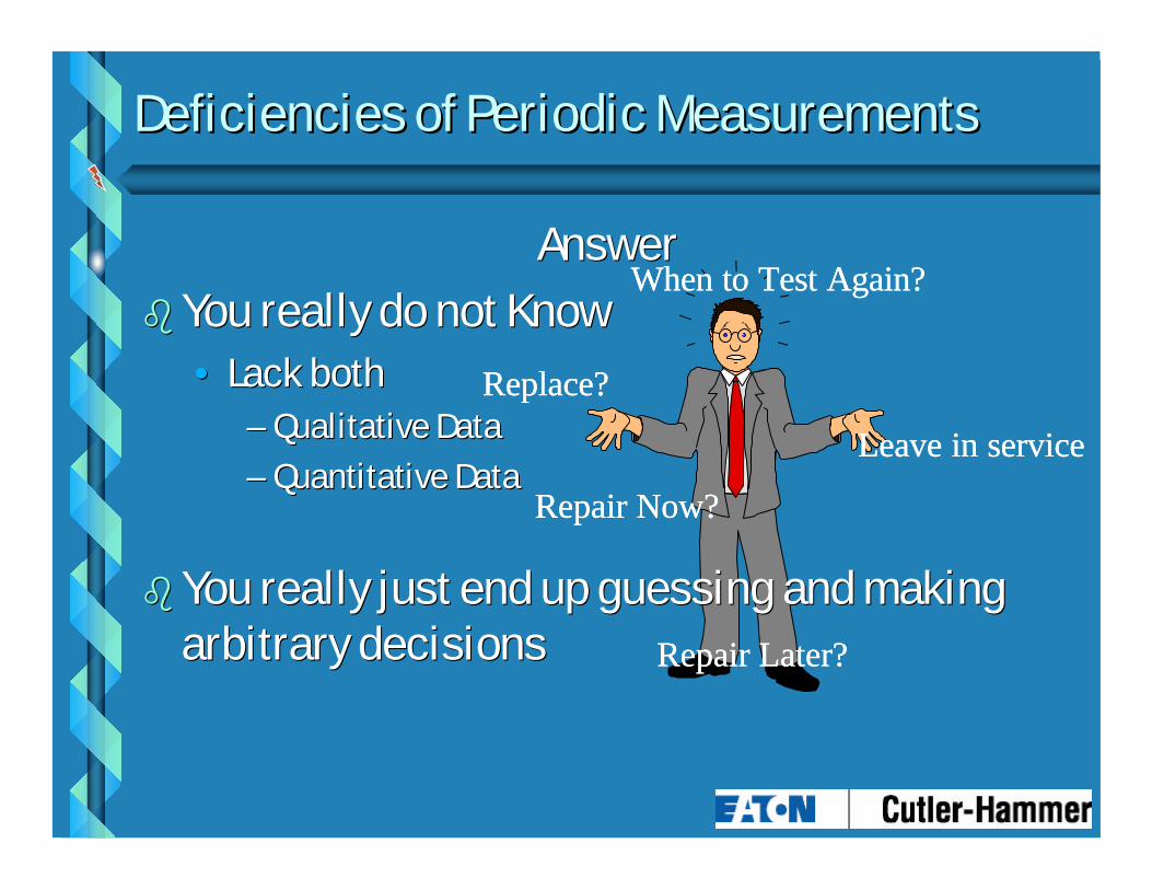
AnswerAnswerbb You really do not KnowYou really do not Know
•• Lack bothLack both–– Qualitative DataQualitative Data–– Quantitative DataQuantitative Data
bb You really just end up guessing and making You really just end up guessing and making arbitrary decisionsarbitrary decisions
When to Test Again?
Repair Now?
Repair Later?
Leave in service
Replace?
When to Test Again?
Repair Now?
Repair Later?
Leave in service
Replace?
Deficiencies of Periodic MeasurementsDeficiencies of Periodic Measurements
bb Time consumingTime consuming•• Labor intensiveLabor intensive•• Usually requires an expertUsually requires an expert
bbOrganizations are being driven to do more with Organizations are being driven to do more with lessless•• Need to take the “work” out of it = LaborNeed to take the “work” out of it = Labor•• Essence of condition based maintenanceEssence of condition based maintenance

Continuous Monitoring Will Save $Continuous Monitoring Will Save $
bb Finding a problem is not left to chance.Finding a problem is not left to chance.•• Find a problem early in the development stageFind a problem early in the development stage•• Make better decisions since you have recent dataMake better decisions since you have recent data•• Repairs are less expensiveRepairs are less expensive
bb Provide info as to type of defect and locationProvide info as to type of defect and location

Continuous Monitoring Will Save $Continuous Monitoring Will Save $
bbNo labor required to perform the testNo labor required to perform the testbbUnnecessary maintenance is reducedUnnecessary maintenance is reducedbb Accurate data since tests are done under Accurate data since tests are done under
actual operating conditionsactual operating conditionsbbNo outage to perform testsNo outage to perform testsbbNo introduction of infant mortality failure No introduction of infant mortality failure
patterns (common to preventive type of patterns (common to preventive type of inspection and testing)inspection and testing)

Continuous Monitoring Will Save $Continuous Monitoring Will Save $
bbNo surprises, reduction in forced outages, No surprises, reduction in forced outages, increased safety to personnelincreased safety to personnel
bbMonitoring of dynamics and correlation of PD Monitoring of dynamics and correlation of PD activity to these dynamicsactivity to these dynamics
bb Provides opportunity for remote diagnosticsProvides opportunity for remote diagnostics•• No need for expert to be in the field on a consistent No need for expert to be in the field on a consistent
basisbasis

Continuous Monitoring Will Save $Continuous Monitoring Will Save $
bbBase evaluation on the equipment’s own Base evaluation on the equipment’s own history and not a comparison to other history and not a comparison to other equipmentequipment•• Makes detecting subtle problems easierMakes detecting subtle problems easier
bbMonitor worsening conditionsMonitor worsening conditions•• Defer RepairsDefer Repairs•• Plan an outagePlan an outage

bb Universal Bushing Sensor is Connected to Universal Bushing Sensor is Connected to Capacitance Tap of a BushingCapacitance Tap of a Bushing
Bushing MonitoringBushing MonitoringChange in Power
Factor & Capacitance
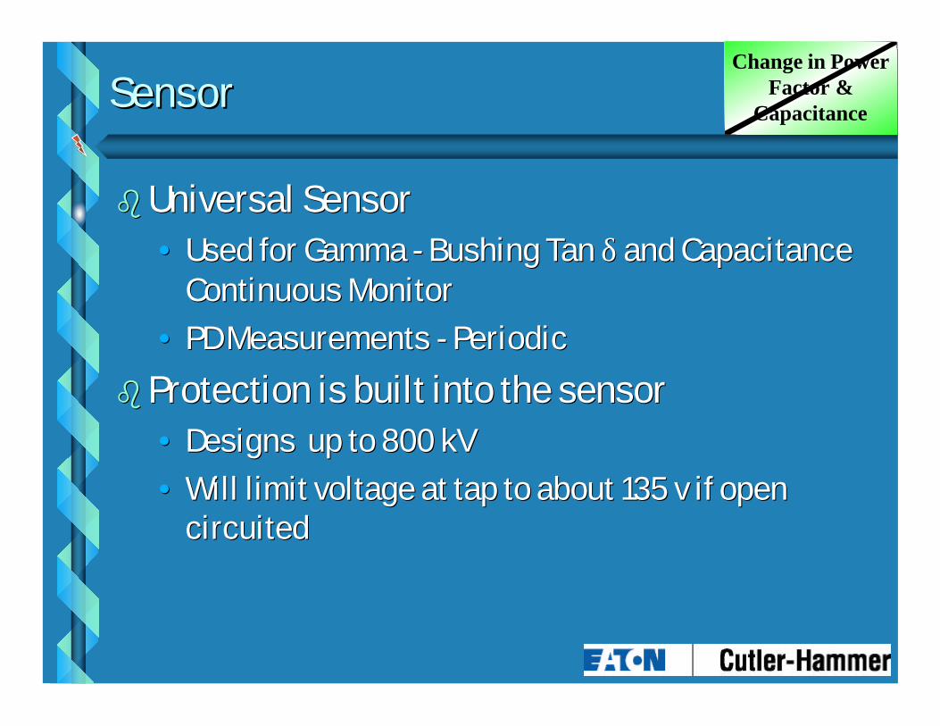
SensorSensor
bbUniversal SensorUniversal Sensor•• Used for Gamma Used for Gamma -- Bushing Tan Bushing Tan δδ and Capacitance and Capacitance
Continuous MonitorContinuous Monitor•• PD Measurements PD Measurements -- PeriodicPeriodic
bb Protection is built into the sensorProtection is built into the sensor•• Designs up to 800 kVDesigns up to 800 kV•• Will limit voltage at tap to about 135 v if open Will limit voltage at tap to about 135 v if open
circuitedcircuited
Change in Power Factor &
Capacitance

Bushing MonitoringBushing MonitoringChange in Power
Factor & Capacitance
( ) ( )γ δ= = +∆
∆ ∆II
CCo o
tan 22
• Thus the current flowing through the Tap is directly proportional to capacitance C1, and a change in that capacitance results in a proportional change in the current.
• Another failure mode is the increase in the dielectric losses of the bushing. Changes in the dielectric losses will also cause a proportional change in the current.

KK ΣΣ
UUCC
UUBB
UUAA
CC1A1A CC1c1cCC1B1B
IIAA IIBB IICC
∆ ∆ II
K - Current Balancing UnitK - Current Balancing Unit ΣΣ - Current Summer - Current Summer
PD Sensors
Block Diagram of On-Line Monitor
Bushing MonitoringBushing MonitoringChange in Power
Factor & Capacitance

InsulGard InsulGard -- G2G2
bb Microprocessor basedMicroprocessor basedbb Gamma & PhaseGamma & Phasebb 1 1 -- Dry Contact AlarmDry Contact Alarmbb 4 4 -- 20 ma Isolated 20 ma Isolated bb 0 0 -- 5vdc non5vdc non--isolatedisolatedbb RS232RS232bb RS485 optionRS485 optionbb Temperature InputTemperature Inputbb On Board MemoryOn Board Memory
Change in Power Factor &
Capacitance

InsulGard InsulGard -- G2G2
bb Self TestSelf Testbb Self CalibrationSelf Calibrationbb Time of Day or IntervalTime of Day or Intervalbb Continuous Watch Continuous Watch
FeatureFeaturebb Auto Auto -- Learn of Temp. Learn of Temp.
DependenciesDependenciesbb Auto TrendingAuto Trending
Change in Power Factor &
Capacitance

Gamma VariationsGamma Variations
bb Temperature can be an important diagnostics Temperature can be an important diagnostics factorfactor
Defective Bushing
Good Bushing
Temperature
Gamma
1%
0.1%
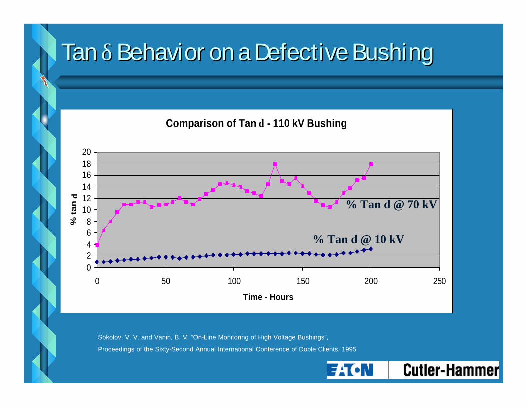
Tan Tan δδ Behavior on a Defective BushingBehavior on a Defective Bushing
Comparison of Tan δ - 110 kV Bushing
02468
101214161820
0 50 100 150 200 250
Time - Hours
% t
an
δ
% Tan δ @ 10 kV
% Tan δ @ 70 kV
Sokolov, V. V. and Vanin, B. V. “On-Line Monitoring of High Voltage Bushings”,
Proceedings of the Sixty-Second Annual International Conference of Doble Clients, 1995

Developing Defect in a 500 kV, 1600 amp Developing Defect in a 500 kV, 1600 amp BushingBushing
Change in Imbalance Current - 500 kV bushing
0
2
4
6
8
0 20 40 60
Time - Days
% Im
bal
ance
Cu
rren
t
Failure
Failure in 57 days
Sokolov, V. V. and Vanin, B. V. “On-Line Monitoring of High Voltage Bushings”,
Proceedings of the Sixty-Second Annual International Conference of Doble Clients, 1995
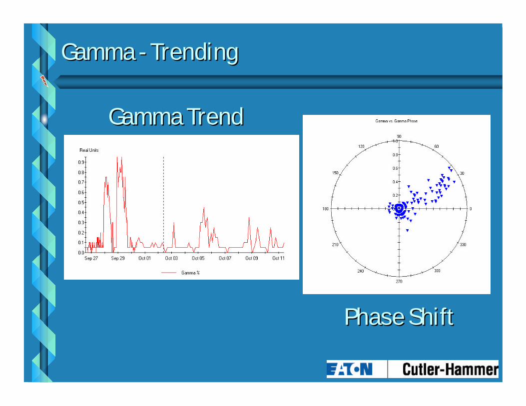
Gamma Gamma -- TrendingTrending
Gamma TrendGamma Trend
Phase ShiftPhase Shift

•• PD is a localized electrical discharge in an PD is a localized electrical discharge in an insulation system that does not completely insulation system that does not completely bridge the electrodesbridge the electrodes
What is Partial Discharge?
Arc or Spark
Phase to Phase or
Phase to Ground

Equivalent Circuit of a PD SiteEquivalent Circuit of a PD SiteAC High Voltage
VOID
AC High Voltage
Ct
Ca
Cv
What is Partial Discharge?

•• Phenomena that only occurs at higher AC Phenomena that only occurs at higher AC voltages (> 2,000 V). Prefer 4 kV and higher.voltages (> 2,000 V). Prefer 4 kV and higher.
•• The higher the voltage the more destructive the The higher the voltage the more destructive the activity.activity.
bb PD is a leading indicator of insulation PD is a leading indicator of insulation breakdown.breakdown.
What is Partial Discharge?

PD Measurement Matrix
15 Degree Windows
Pu
lse
Mag
nit
ud
e
-11-10
-9-8-7-6-5-4-3-2-10123456789
1011
0 15 30 45 60 75 90 105
120
135
150
165
180
195
210
225
240
255
270
285
300
315
330
345
360
Partial Discharge Pulses
Negative Polarity
- PositivePolarity
+
Cycle 1
Cycle 2
To N samples
PD Stops a 90 degrees PD Stops at 270 degrees
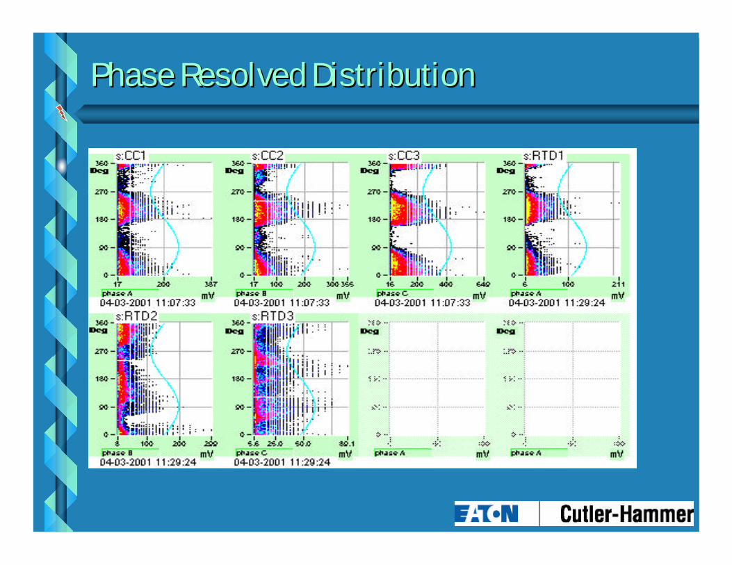
Phase Resolved DistributionPhase Resolved Distribution

PD PD -- TransformersTransformers
bb Periodic Only at this timePeriodic Only at this timebbMain issue is noiseMain issue is noise
•• Severe Corona exists at these higher voltagesSevere Corona exists at these higher voltages•• Specialized Analyzer is requiredSpecialized Analyzer is required•• The UPDA is the only known Analyzer that exists The UPDA is the only known Analyzer that exists
that can perform the necessary noise rejectionthat can perform the necessary noise rejection
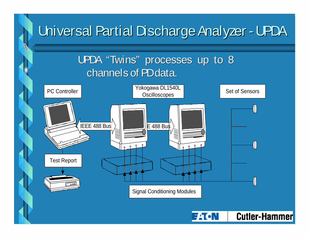
UPDA “Twins” processes up to 8 UPDA “Twins” processes up to 8 channels of PD data.channels of PD data.
Universal Partial Discharge Analyzer Universal Partial Discharge Analyzer -- UPDAUPDA
IEEE 488 Bus
Yokogawa DL1540LOscilloscopes
Signal Conditioning Modules
Set of SensorsPC Controller
Test Report
IEEE 488 Bus

UPDA “Twins” processes up to 8 UPDA “Twins” processes up to 8 channels of PD data channels of PD data -- SimultaneouslySimultaneously
UPDAUPDA

bbMain sources of noise: Main sources of noise: •• Thyristor’s firing Thyristor’s firing •• Digital noise from control electronicsDigital noise from control electronics•• Radio station operation Radio station operation •• Arcing or sparking originating at the facility Arcing or sparking originating at the facility
Signal Processing: Signal Processing: Noise Cancellation TechniquesNoise Cancellation Techniques
An analyzer must detect PD signal in presence of external pulse noises with 10 times greater amplitude

Problems SolutionsLow LevelBackground Noise
• Noise identification and cancellation based on statisticaldigital waveform analysis.
Synchronous Noise • Detection of thyristor firing power frequency phaseintervals using superposition of series of acquisitions.
PulseCrosscouplingNoise
• Comparison of pulse magnitudes occurring simultaneouslyin different channels to determine signal origination.
Special Situations • Any of the channels can be designated as a “noise” sourceto discard simultaneous pulses in other channels.
• Full control of pulse parameters to filter out all noisepulses.
Signal Processing: Signal Processing: Noise Cancellation TechniquesNoise Cancellation Techniques

UPDA As an Effective ToolUPDA As an Effective Tool
bb After effective noise elimination techniques were After effective noise elimination techniques were confirmed. The residual noise level did not exceed 50pC.confirmed. The residual noise level did not exceed 50pC.
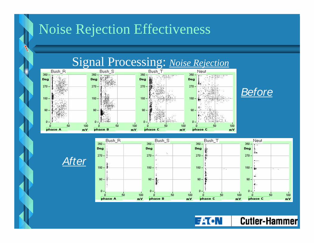
Signal Processing: Noise Rejection
Noise Rejection Effectiveness
Before
After

750 kV 750 kV -- Location of FaultLocation of Fault
C r e e p i n gd i scharge
B u s h i n g
W i n d i n g
Bar r i e r
Par t ia lDi scharges
Shield
Discharges caused by Water leaking in due to a bad gasket

750 kV Auto Transformer750 kV Auto Transformer
Creeping Discharge within Pressboard Barrier
Discharge in excess of
10,000 pC

Case StudyCase Study
bb ArgentinaArgentina•• Tested 21 Transformers Tested 21 Transformers -- GSUGSU
–– 13.8 kV generator side13.8 kV generator side–– 500 kV connected directly to SF6 Bus500 kV connected directly to SF6 Bus

Test SetupTest Setup
U V WSensor
Bush_RSensorBush_S
SensorBush_T
SensorNeut
SensorGen
500 kV Winding 13.8 kV Winding

Noise From GeneratorNoise From Generator
1 >
2 >
3 >
4 >
1) Bush_R: 40 mVolt 500 ns 2) Bush_S: 40 mVolt 500 ns 3) Bush_T: 40 mVolt 500 ns 4) Gen_R: 200 mVolt 500 ns
1 >
2 >
3 >
4 >
1) Bush_R: 50 mVolt 2 ms 2) Bush_S: 50 mVolt 2 ms 3) Bush_T: 50 mVolt 2 ms 4) Gen_T: 2 Volt 2 ms
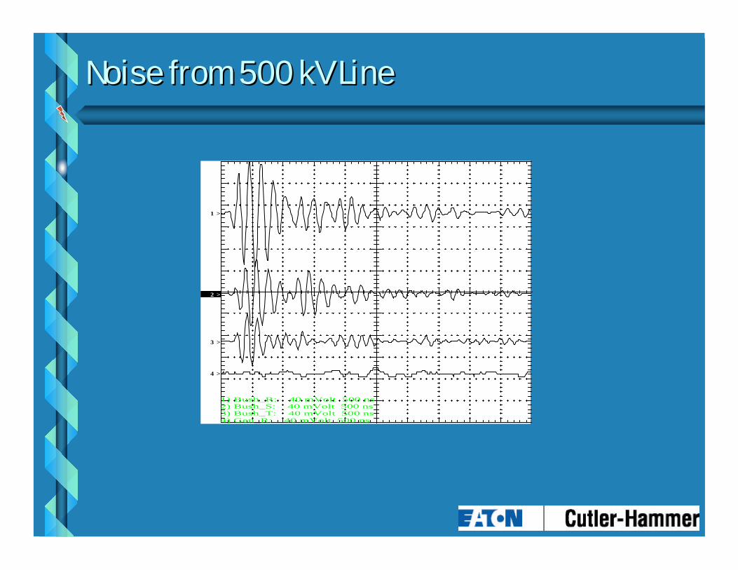
Noise from 500 kV LineNoise from 500 kV Line
1 >
2 >
3 >
4 >
1) Bush_R: 40 mVolt 500 ns 2) Bush_S: 40 mVolt 500 ns 3) Bush_T: 40 mVolt 500 ns 4) Gen_R: 40 mVolt 500 ns

Transformer 18 Transformer 18 -- Neutral SensorNeutral Sensor
1 >
2 >
3 >
4 >
1) Bush_R: 100 mVolt 2 ms 2) Bush_S: 100 mVolt 2 ms 3) Bush_T: 100 mVolt 2 ms 4) Neut: 100 mVolt 2 ms
4 >
5 >
6 >
4) Neut: 40 mVolt 200 ns 5) Neut: 20 mVolt 200 ns 6) Neut: 20 mVolt 200 ns
Problems with No-load Tap Changer
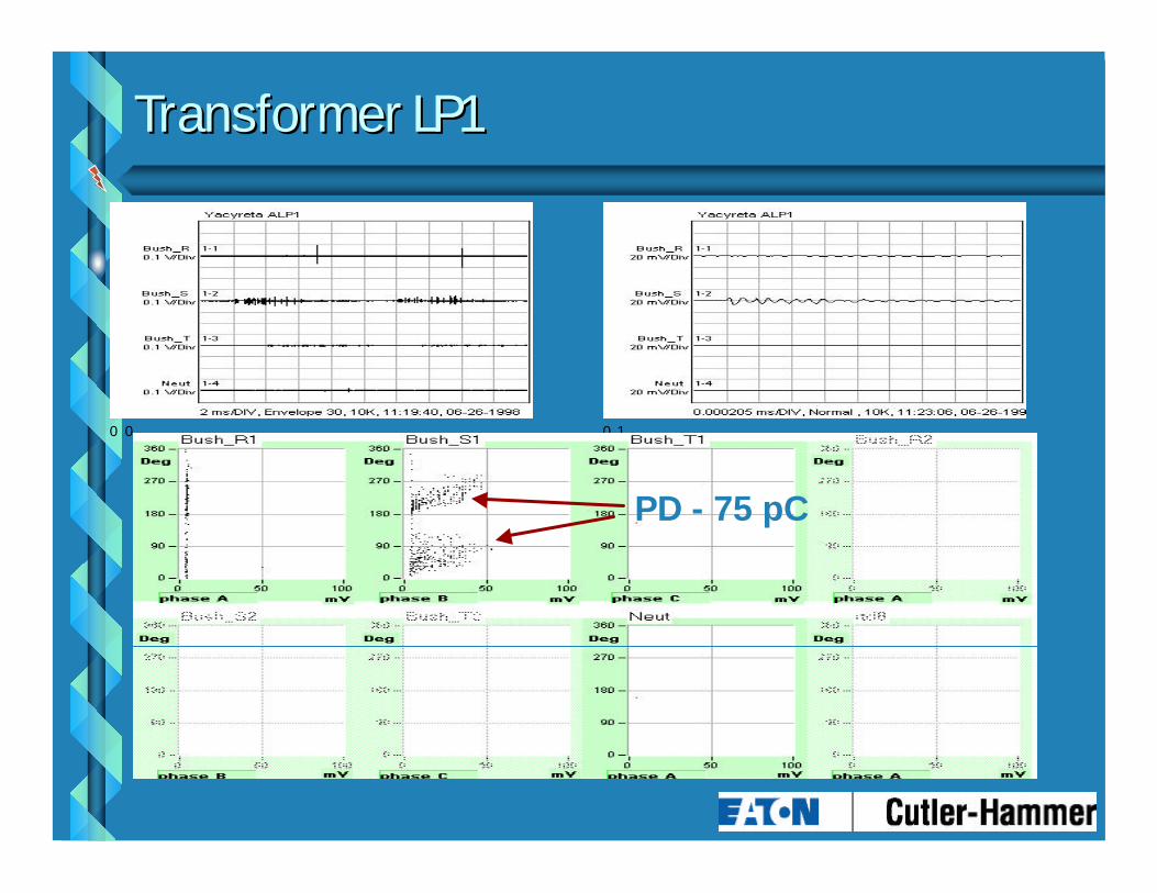
Transformer LP1Transformer LP1
0 0 0 1
PD - 75 pC

PD LevelsPD Levels
bb 300 300 pC pC maximum maximum •• No permanent damage to paperNo permanent damage to paper
bb > 1,000 > 1,000 pC pC •• Permanent Damage to paper occursPermanent Damage to paper occurs
PD Measurements PD Measurements -- Other EquipmentOther Equipment
bbContinuous Monitoring 4 kV Continuous Monitoring 4 kV -- 38 kV38 kV•• MotorsMotors•• GeneratorsGenerators•• SwitchgearSwitchgear•• Bus DuctBus Duct
Case StudiesCase Studies
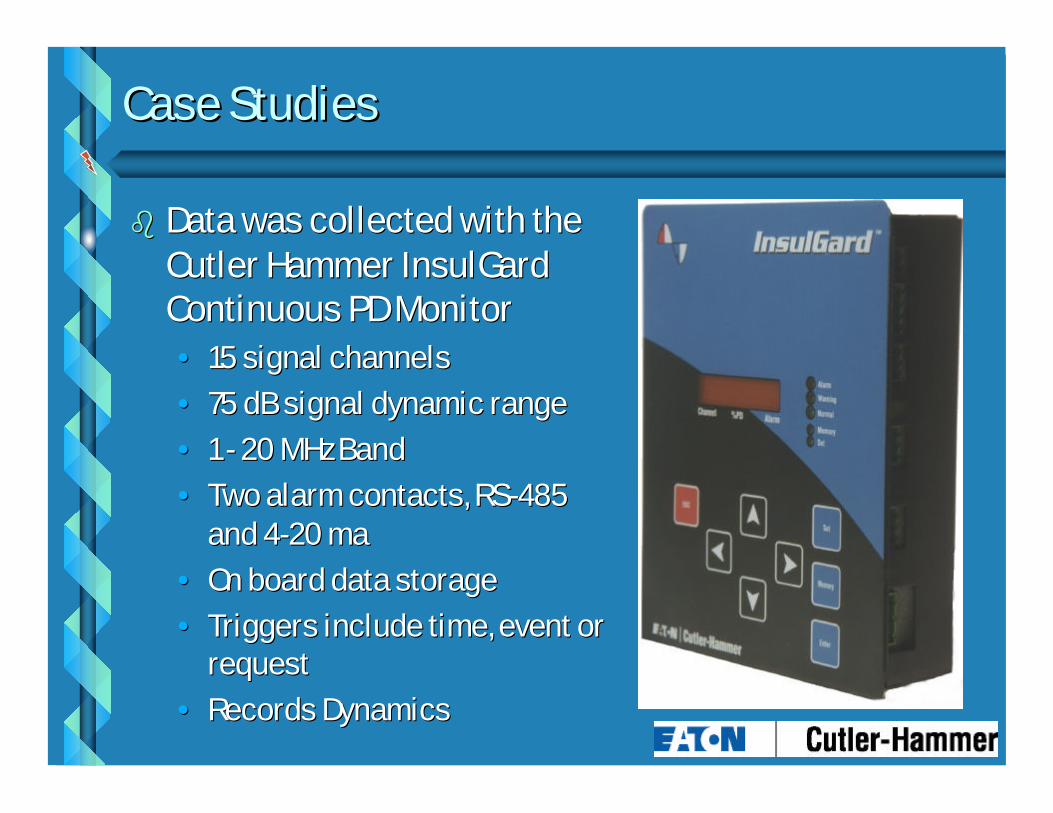
bb Data was collected with the Data was collected with the Cutler Hammer InsulGard Cutler Hammer InsulGard Continuous PD MonitorContinuous PD Monitor
•• 15 signal channels15 signal channels•• 75 dB signal dynamic range75 dB signal dynamic range•• 1 1 -- 20 MHz Band20 MHz Band•• Two alarm contacts, RSTwo alarm contacts, RS--485 485
and 4and 4--20 ma20 ma•• On board data storageOn board data storage•• Triggers include time, event or Triggers include time, event or
requestrequest•• Records DynamicsRecords Dynamics
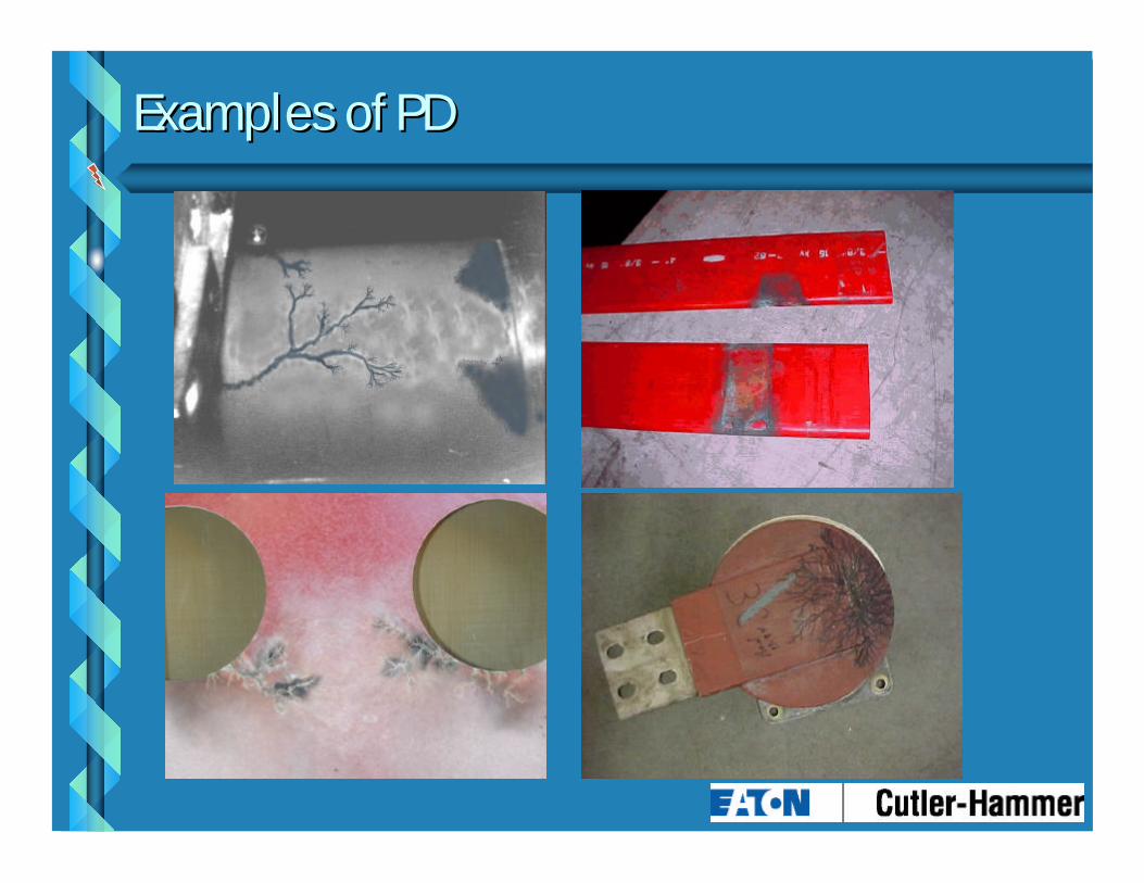
Examples of PDExamples of PD

Examples of PDExamples of PD

What Is PreventWhat Is Prevent
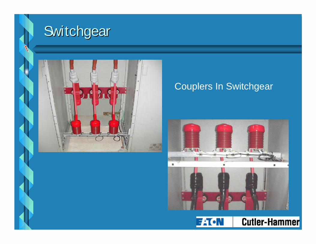
Couplers In Switchgear
SwitchgearSwitchgear

Where to Install CouplersWhere to Install Couplers
Zone of Protection
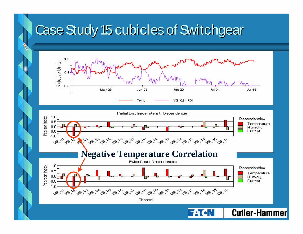
Case Study 15 cubicles of SwitchgearCase Study 15 cubicles of Switchgear
Negative Temperature Correlation

Correlation of PDI and HumidityCorrelation of PDI and Humidity
Something Happened
PT - removed ultrasonic
Positive Humidity Correlation
Something Started Here
SummarySummary
bbOnOn--Line Monitoring and Testing for large Power Line Monitoring and Testing for large Power Transformers is HereTransformers is Here•• Periodic PDPeriodic PD•• Continuous Monitoring of changes in bushing Continuous Monitoring of changes in bushing
capacitance and power factorcapacitance and power factor
bbContinuous monitoring for PD is available on Continuous monitoring for PD is available on other equipment rated less than 38 kVother equipment rated less than 38 kV

SummarySummary
bbContinuous Monitoring Can Save MoneyContinuous Monitoring Can Save Money•• No labor is required to conduct testsNo labor is required to conduct tests•• Labor is freed up for other important tasksLabor is freed up for other important tasks•• More accurate data is availableMore accurate data is available•• Finding a problem is not left to chanceFinding a problem is not left to chance•• Reduction of unnecessary maintenanceReduction of unnecessary maintenance•• Prioritize EquipmentPrioritize Equipment