Embed Size (px)
Citation preview

Thonstad, Bao, Weigand, Main, Lew 2018 PCI/NBC
NEW CONNECTIONS FOR ENHANCING ROBUSTNESS OF PRECAST CONCRETE FRAME STRUCTURES
Travis Thonstad, Yihai Bao, Jonathan M. Weigand, Joseph A. Main, and H.S. Lew
National Institute of Standards and Technology, Gaithersburg, MD
ABSTRACT
A recent experimental and computational study of two full-scale precast concrete moment-frame assemblies under a column removal scenario revealed vulnerabilities in the moment connections arising from (a) local bending of reinforcing bars due to eccentricity in the tensile load path between components and (b) reduction in the ductility of reinforcing bars due to welding. To overcome these issues with the tested prototype connections, three new alternative connections, which incorporate welded link plates, threaded bars, and grouted bars, respectively, are proposed to enhance the robustness of precast concrete frame structures. Computational analyses of the experimental column removal scenario were conducted for one of the tested assemblies and for geometrically identical assemblies that incorporated the alternative connection details. The robustness index, a normalized measure of the dynamic load carrying capacity of a system under sudden column removal, was used to quantify and compare the performance of the alternative connections based on the analysis results. The assemblies with the welded link plate, threaded bar, and grouted bar connections had robustness indices 50 %, 130 %, and 220 % greater, respectively, than that of the assembly with prototype connections. This paper describes the three proposed connection concepts, presents results from numerical modeling and outlines plans for component and full-scale connection testing.
Keywords: Disproportionate Collapse, Precast Concrete Buildings, Structural Robustness, Finite Element Analysis, Moment Resisting Connections.
Thonstad, Bao, Weigand, Main, Lew 2018 PCI/NBC
1
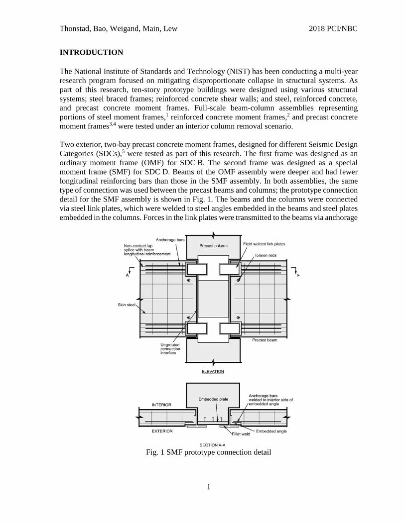
INTRODUCTION The National Institute of Standards and Technology (NIST) has been conducting a multi-year research program focused on mitigating disproportionate collapse in structural systems. As part of this research, ten-story prototype buildings were designed using various structural systems; steel braced frames; reinforced concrete shear walls; and steel, reinforced concrete, and precast concrete moment frames. Full-scale beam-column assemblies representing portions of steel moment frames,1 reinforced concrete moment frames,2 and precast concrete moment frames3,4 were tested under an interior column removal scenario. Two exterior, two-bay precast concrete moment frames, designed for different Seismic Design Categories (SDCs),5 were tested as part of this research. The first frame was designed as an ordinary moment frame (OMF) for SDC B. The second frame was designed as a special moment frame (SMF) for SDC D. Beams of the OMF assembly were deeper and had fewer longitudinal reinforcing bars than those in the SMF assembly. In both assemblies, the same type of connection was used between the precast beams and columns; the prototype connection detail for the SMF assembly is shown in Fig. 1. The beams and the columns were connected via steel link plates, which were welded to steel angles embedded in the beams and steel plates embedded in the columns. Forces in the link plates were transmitted to the beams via anchorage
Fig. 1 SMF prototype connection detail

Thonstad, Bao, Weigand, Main, Lew 2018 PCI/NBC
2
bars, which were welded to the interior faces of steel angles. The SMF connections incorporated three no. 11 (36M) anchorage bars, while the OMF connections incorporated two no. 10 (32M) anchorage bars. The test setup for the SMF precast concrete frame assembly is shown in Fig. 2; the test setup for the OMF assembly was identical. Because of space limitations, the spans in the tested assemblies were reduced to 300 in. (7620 mm) from the prototype building span of 360 in. (9144 mm). Longitudinal bracing was provided between the tops of the exterior columns to restrain in-plate movement. Lateral bracing was provided at midspan of the beams and at the center column. Similar to the cast-in-place concrete moment frame assemblies tested previously,2 failure of the precast concrete frame assemblies involved fracture of reinforcing bars at the bottom of the beams near the center column. However, fracture of the reinforcing bars occurred at much smaller vertical displacements of the center column for the precast concrete frame assemblies: 2.49 in. (63.2 mm) for the SMF assembly and 5.66 in. (144 mm) for the OMF assembly.3,4 For comparison, the cast-in-place concrete SMF assembly, which had shorter span lengths and beams with higher span-to-depth ratios, was able to withstand vertical displacements in excess of 44.5 in. (1130 mm) prior to failure.2
Fig. 2 Experimental configuration for the SMF specimen (adapted from Main et al.3).
The large displacement capacity of the cast-in-place concrete SMF assembly allowed it to develop significant catenary action prior to failure. This led to an increase in load carrying capacity after the vertical resistance due to flexural and arching action was depleted at smaller vertical displacements. The potential for development of catenary action in the precast concrete frames is limited by the low span-to-depth ratios of the beams (3.1 and 4.8 for the precast OMF and SMF assemblies, respectively, compared with 9.2 for the cast-in-place SMF assembly). Experimental data from a large set of reinforced concrete assemblies showed that significant catenary action was only developed in those assemblies with beams that had span-to-depth ratios exceeding 6.0.6 Although the potential for development of catenary action in the precast concrete frames is limited, improvements in the connection design leading to larger vertical

Thonstad, Bao, Weigand, Main, Lew 2018 PCI/NBC
3
displacements at the center column could be expected to increase the load carrying capacity by further mobilizing the development of flexural and arching action . In the precast concrete frame assemblies, fracture of the anchorage bars occurred at the end of the flare-bevel-groove welds between the anchorage bars and the embedded angles. Fracture was attributed to flexure of the bars, due to the eccentricity of the tensile force transfer path, in combination with reduced ductility of the bars in the heat-affected zone caused by welding.3,4 To determine the reduction in ductility of the bars that contributed to this failure, uniaxial tension testing under concentric loading was performed on a welded bar extracted from a prototype connection,3 as shown in Fig. 3. The effect of welding was shown to result in a decrease in the strain at fracture. In combination with flexure due to connection eccentricities, this reduction in ductility caused the anchorage bars to fracture significantly below their nominal tensile capacity.3,4
Fig. 3 Reduced ductility of welded no. 11 anchorage bar (adapted from Main et al.3)
The robustness of the precast frames under sudden column loss was estimated from the static push-down tests and the applicable gravity loading on the prototype structure using an energy-based approach;3 the procedure is shown schematically in Fig. 4. This estimation assumes that the gravity loads are insufficient to cause collapse and that the frame deforms in a single, predominant mode. In such a system, the kinetic energy is zero at the point of maximum displacement, and the work done by external loads can be equated to the internal energy of the system at a given deformation. Using this energy-based approach, a robustness index R can be defined as a measure of the robustness of a structural system under sudden column loss:7 𝑅𝑅 = 1
𝑃𝑃𝐺𝐺Δu∫ 𝑃𝑃(Δ)Δu0 𝑑𝑑Δ , (1)
where 𝑃𝑃(Δ) is the force-displacement response of the system obtained from static pushdown loading at the location of the removed column, Δ is the vertical displacement at the removed column, Δu is the displacement at the ultimate static load, and PG is the force in the column to

Thonstad, Bao, Weigand, Main, Lew 2018 PCI/NBC
4
be removed under service-level gravity loading G, which is commonly taken as G = 1.2D + 0.5L, where D is dead load and L is live load.7
Fig. 4 Energy-based estimation of capacity under sudden column loss
Robustness indices of 1.11 and 1.02 were obtained for the OMF and SMF precast assemblies, respectively,3,8 which means that the estimated ultimate capacities exceeded the service-level gravity loading by 11 % and 2 %. These robustness indices correspond to the prototype span length of 30 ft (9144 mm) and were obtained using computational models, since the experimental assemblies had reduced span lengths of 25 ft (7620 mm). Given the uncertainty in the computational models and the sensitivity to certain material and geometric parameters, as discussed subsequently, the ultimate capacity of these frames may be insufficient to resist collapse under a sudden column removal for the applicable service gravity loads. To increase the robustness of precast concrete frames under column removal scenarios, three potential strategies were identified for enhancing the performance of the connections:
1. Enhance the force and deformation capacity of the welded link plate connection by a. Reducing the eccentricity in the tensile force transfer path, and b. Promoting yielding and plastic deformation of the link plates.
2. Replace the welded link plate connection with a threaded rod connection. 3. Replace the welded link plate connection with a grouted bar connection.
These modifications were meant to increase both the ultimate load and the corresponding deformation that can be sustained by the connections, thus enabling flexural and arching action to be more fully mobilized in resisting column loss. ENHANCED CONNECTIONS The first connection type (Type A) uses a modified link plate detail to attach the precast beams to the precast columns; the second connection type (Type B) employs high-strength threaded steel rods; and the third connection type (Type C) uses large-diameter, grouted reinforcing bars.

Thonstad, Bao, Weigand, Main, Lew 2018 PCI/NBC
5
WELDED LINK PLATE (TYPE A) The revised welded link plate connection is shown in Fig. 5. The Type A connection incorporates the minimal modifications to the prototype configuration necessary to reduce the eccentricity of the tensile force transfer path and improve connection ductility. The construction sequence and beam reinforcement are otherwise identical. In a Type A connection, anchorage bars are welded to the exterior faces of an embedded WT section in the beam, rather than to the interior faces of an angle, as was done in the prototype configuration. This aligns the forces in the link plate and the anchorage bars, thus reducing flexural stresses due to eccentricities. The flexural stiffness of the WT section also reduces flexural stresses in the anchorage bars by limiting the curvature that can develop between the link plate and the anchorage bars. The link plates are reduced in width compared with the prototype connection, so that the expected tensile strength of the link plate is roughly equal to that of the three anchorage bars. A free length is added between the welds, to promote plastic deformation of the link plates by spreading the yielding over an increased length. By reducing the distance between the welds on the embedded column plate, adequate weld length parallel to the beam centerline can be maintained.
Fig. 5 Type A connection detail

Thonstad, Bao, Weigand, Main, Lew 2018 PCI/NBC
6
THREADED ROD (TYPE B) The threaded rod connection is shown in Fig. 6. The Type B connection eliminates welding of critical connection components in the field. The beams and columns are connected via threaded rods, which were designed to have a tensile capacity approximately equal to that of the three anchorage bars in the prototype design. The threaded rods run through ducts within the beam, are anchored by a nut that bears against an embedded rectangular steel hollow structural section (HSS) in the beam, and terminate at a standard steel coupler embedded in the column. The threaded rods are tightened to wrench-tight.
Fig. 6 Type B connection detail
Axial forces in the threaded rods are transferred to the beams through bearing of the rectangular HSS section on the beam concrete and through flexural bars connected to the rectangular HSS section opposite the threaded rod. These flexural bars could be connected to the HSS section using threaded ends with nuts, or by welding. The HSS section is shown flush with the front face of the beam in Fig. 6, to allow continuous longitudinal reinforcement to pass on the opposite side. This is a consequence of the prototype geometry, and for other beam geometries, the HSS section could be embedded at mid-width in the beam. This arrangement would allow reinforcement to pass by on either side and would result in a symmetric beam section.

Thonstad, Bao, Weigand, Main, Lew 2018 PCI/NBC
7
GROUTED BAR (TYPE C) The grouted bar connection is shown schematically in Fig. 7. The Type C connection avoids the use of welded link plates, in favor of grouted reinforcing bars in ducts. The beams and column are connected using large diameter reinforcing bars, designed to have a tensile capacity approximately equal to that of the three anchorage bars in the prototype design. These bars run continuously through the ducts in both the beams and columns. These ducts, as well as the beam-column interface, are then grouted to complete the connection. To slide the bars through the column and into the adjacent beam, troughs are cast into the beam extending a short distance into the span. The corrugated steel ducts are located at the center of the beam cross-section, to further reduce eccentricities of tensile force transfer path.
Fig. 7 Type C connection detail
Tension forces from the anchorage bars are transferred to the beam through bond. Previous bond tests of large-diameter bars grouted in ducts have shown that a bonded length of roughly 10 bar diameters is sufficient to reach the ultimate capacity of the bar under monotonic loads4. To increase their elongation at the connection, the bars are locally debonded through the column and in the beam, near the grouted beam-to-column interface.

Thonstad, Bao, Weigand, Main, Lew 2018 PCI/NBC
8
NUMERICAL MODELING The performance of each modified connection type was evaluated through high-fidelity finite element modeling of the connections. Each connection type was evaluated under two loading scenarios: (1) direct tension applied to a single connection and (2) increasing vertical displacements applied at the center column of a two-span frame assembly. The modeling approach used in this proof-of-concept study followed that of Main et al.;3 this approach was experimentally validated against the precast concrete OMF and SMF assembly tests. A summary is given here for context; detailed information about the modeling approach is provided by Main et al.3 The concrete components were modeled using 8-node constant stress solid elements, the embedded steel components were modelled using 8-node fully integrated solid elements, and the reinforcement was modeled using beam elements. The mesh size of the concrete elements was roughly 2 in. (51 mm), with a maximum aspect ratio of approximately 2.5. Stirrups and discontinuous bars were modeled assuming perfect bond; grouted bars in the Type C connection were assumed to have degrading bond stiffness, calibrated using experimental data from bar pull-out tests.9 A segment-based contact model prevented interpenetration and enabled bearing of the components within the assembly. A coefficient of friction of 0.3 was assumed. Based on previous comparisons of computational models with experimental measurements from the tested assemblies,3 the estimated uncertainty in the ultimate capacities obtained from the computational models is ±8 %. This uncertainty corresponds to test specimens for which measured material properties were available. Sensitivity studies were also performed to investigate the influence of factors that would vary in construction practice, and the ultimate capacities were found to be particularly sensitive to the ductility of the anchorage bars, as influenced by welding, and the initial air gap between the beams and columns, which affects the development of arching action.3 Realistic variations in these factors were found to alter the ultimate capacities of the assemblies by as much as 35 %.3 By reducing the influence of welds on connection failure and by eliminating air gaps through grouting of connection interfaces, the enhanced connections proposed in this study are expected to have reduced sensitivity to such construction-related factors, thus reducing the uncertainty in the performance of the enhanced connections. This aspect of the connection performance will be investigated in future sensitivity studies. Because the focus of this proof-of-concept study is on the relative performance of alternative connection types, material and geometric properties are assumed in all models to be consistent with those of the tested prototype specimen. The only factor that is varied between models is the type of connection, to focus on the potential performance improvements of the alternative connection concepts. MATERIAL PROPERTIES The material properties for the components were identical for all the analyzed models where applicable. A continuous surface cap model10 and an isotropic elastic-plastic material11 were used to capture the nonlinear behavior of the concrete and steel materials, respectively. The

Thonstad, Bao, Weigand, Main, Lew 2018 PCI/NBC
9
compressive strength of the concrete was taken as 5785 psi (39.9 MPa), and the material model parameters were taken as the recommended values for this compressive strength from FHWA-HRT-058-063.10 The material properties used for the steel components are summarized in Table 1. In all the steel materials, the elastic modulus was taken as 29 000 ksi (200 GPa).
Table 1 Steel material model parameters
Component Yield Stress ksi (MPa)
Ultimate Stress ksi (MPa)
Plastic Strain at Ultimate Stress
Plate 42.0 (290) 84.2 (581) 0.4300 Embedded Steel Sections 42.0 (290) 84.2 (581) 0.4300 No. 4 bars 74.2 (491) 95.8 (661) 0.0826 No. 9 bars 66.6 (459) 97.6 (673) 0.0924 No. 11 bars 68.0 (469) 95.0 (655) 0.0833 No. 14 bars 67.5 (465) 95.3 (657) 0.0969 Threaded rod 105.0 (724) 125.0 (862) 0.0457
CONNECTION UNDER DIRECT TENSION The fracture of the reinforcing bars observed in the tests of the prototype specimen was primarily due to the tensile forces transferred via the link plates. Therefore, it is expected that increasing the tensile capacity of the connections and the corresponding tensile deformation at fracture should lead to improved structural performance, relative to the tested assembly, under a column removal scenario. The performance of the alternative connection details was evaluated by considering a single connection with the end of the beam subjected to increasing horizontal displacement, as shown in the insert of Fig 8. The tops of the column segments were prevented from moving by two lines of rigid contact elements, and the bases of the column segments were held fixed. The tension-load-displacement curves of the prototype and alternative connections are shown in Fig. 8. The peak loads of the assemblies with the alternative connections were comparable to each other and were roughly 40 % larger than the peak load obtained for the prototype connection. This was expected, because the tensile capacity of the threaded rod and large diameter bars were selected to be comparable to the total capacity of the three anchorage bars in the Type A and prototype connections, and the prototype connection sustained premature fracture of the anchorage bars 3,4. The displacements corresponding to the peak loads were significantly larger for the assemblies with the alternative connections: roughly 200 %, 1000 %, and 700 % larger than that of the prototype connection for the Type A, Type B, and Type C connections, respectively.

Thonstad, Bao, Weigand, Main, Lew 2018 PCI/NBC
10
Fig. 8 Numerical analyses of connections under uniaxial tension.
TWO-SPAN FRAME ASSEMBLY To further evaluate the performance of the alternative connection details, frames with the same geometry as the tested prototype SMF specimen, but with three alternative connections concepts, were analyzed under an interior column removal scenario. The model of the prototype SMF specimen had been previously validated against experimental data,3 and was used as a starting point for the subsequent models. Fig. 9 shows the load-displacement responses of the frame assemblies with the alternative connection types.
Fig. 9 Numerical analysis of frame assemblies under column removal.

Thonstad, Bao, Weigand, Main, Lew 2018 PCI/NBC
11
The assembly with Type A connections had a similar initial stiffness and similar failure mode to the prototype assembly; the anchorage bars at the bottom of the beams fractured near the center column stub. However, the peak load was about 80 % greater than that of the assembly with prototype connections. The peak load of the assembly with Type B connections exceeded the capacity of the assembly with Type A connections by roughly 20 % and exceeded the capacity of the assembly with prototype connections by roughly 120 %. The larger stiffness for the Type B connection resulted largely from grouting the interface between the precast beams and columns, which was not done in the frames with the prototype or Type A connections. Grouting the beam-to-column interface in the Type A connection would be expected to result in similar increases in stiffness, associated with an earlier onset of arching action. The failure mode of the assembly with Type B connections differed from the failure mode observed in the other two assemblies. Following the peak vertical load, the resistance of the connection gradually decreased due to distributed concrete damage within the span of the beam between the connections. The peak load of the assembly with the Type C connections exceeded the vertical load carrying capacity of the assemblies with the prototype, Type A, and Type B connections by roughly 190 %, 60 %, and 30 %, respectively. This increase in load carrying capacity was largely attributed to additional arching action. However, it should be noted that developing significant arching action in the modeled assembly relies on the behavior of the column segments under large shear forces, which was not specifically validated in the previous precast frame studies,3,8 since failure of the connections occurred prior to the development of significant arching action. The eventual failure of the assembly with Type C connections was governed by fracture of the grouted bars running through the center column segment. Table 2 quantifies the improvement to the robustness of the precast frames under a sudden column loss using the robustness index, given in Equation 1. The robustness indices of the alternative connection concepts were normalized to the prototype connection for direct comparison.
Table 2 Normalized robustness indices of modeled precast frames. Connection type Normalized robustness index
Prototype 1.0 Type A 1.5 Type B 2.3 Type C 3.2
The assembly with the Type A connection, representing the minimal modifications necessary to address the shortcomings of the prototype connection identified by Main et al.,3,8 had a 50 % increase in robustness under a sudden column loss. The models of the assemblies with Type B and Type C connections, which both eliminated the link plates and included grouted beam-to-column interfaces, had 130 % and 220 % larger robustness indices than the prototype frame, respectively. These analyses show that the proposed alternative connection designs have the potential to enhance the robustness of a precast concrete frame under an interior column removal scenario. Experimental validation is needed to verify these increases in performance.

Thonstad, Bao, Weigand, Main, Lew 2018 PCI/NBC
12
PLANNED EXPERIMENTAL TESTING Experimental testing is currently underway to verify the performance of the new alternative connection details and to further validate key aspects of the high-fidelity finite element models, including bond and bearing of the steel components within the beam. These tests will also be used to further refine the connection concepts, as appropriate; and develop reduced-order modeling approaches that can be implemented in system-level numerical simulations. Uniaxial tension tests on components of the precast frame assemblies are underway. These tests will focus on the tensile force transfer path from the beam to the column, which plays a critical role in the connection performance. First, full-scale components of both the prototype and the Type A connection detail will be tested, to validate the behavior of the improved welded link plate detail. Second, scaled partial-depth assemblies will be tested to estimate the relative performance of the new connection details in terms of the ultimate strengths and deformation capacities of the connections in tension. Testing of full-scale, cantilever, beam-to-column assemblies that utilize the new connection concepts is planned. The setup for these tests is shown schematically in Fig. 10. These assemblies will incorporate the enhanced connections, and will include any improvements that are identified through the component testing.
Fig. 10 Full-scale connection test setup.

Thonstad, Bao, Weigand, Main, Lew 2018 PCI/NBC
13
Axial and rotation demands will be applied quasi-statically to the cross section at the end of the cantilever beams in the connection assembly; a similar approach has been used previously to test steel gravity connections.12 Two actuators will be aligned with the beam axis and one (or two) will be oriented transversely. The applied displacements and rotations will be determined by assuming an antisymmetric response for the hypothetical connection at the other end of the beam, which requires zero axial displacement and zero bending moment at mid-span. The actuators oriented axially along the beam centerline will apply the forces due to compressive arching action (at small rotations) and catenary action (at large rotations). The benefit of this arrangement is that an arbitrary degree of longitudinal restraint can be applied to the connection, to assess the influence of both flexural and arching action on frame performance under a column loss scenario. SUMMARY AND DISCUSSION Connections between precast concrete components must facilitate rapid on-site assembly and may be required to provide sufficient structural robustness to prevent disproportionate collapse under a column removal scenario. A recent experimental study on two precast concrete frame assemblies under a column removal scenario revealed vulnerabilities in the precast concrete moment frame connections arising from the eccentricity of the tensile force transfer path between components and a reduction in the ductility of reinforcing bars in the heat-affected zone due to the welding.3,4,8 Three new alternative connections were proposed to enhance the robustness of precast concrete frame structures. One connection (Type A) represented the minimal modifications to the original connection required to reduce the eccentricities in the tensile force transfer path. The other connections, one with a threaded rod connection (Type B) and one with a grouted bar connection (Type C), were designed to both eliminate the eccentricity of the force transfer path and avoid the requirement of welding critical connection components on-site. Numerical models of the previously tested SMF assembly,3,4 with connections replaced by the proposed connection types, were used to evaluate the robustness of the proposed connection designs. The performance of each of the frames was compared to an experimentally validated model on the SMF assembly with the prototype connections. The robustness index, a measure of the dynamic load carrying capacity of a system in comparison with service gravity loads, was used to quantify increases in structural robustness of the assemblies with the alternative connections. The assemblies with the Type A, Type B, and Type C connections had robustness indices 50 %, 130 %, and 220 % larger than that of the assembly with prototype connections. The proposed connection types show potential for enhancing the robustness of precast concrete frame structures. Full-scale experimental investigation of these new connection types is planned.

Thonstad, Bao, Weigand, Main, Lew 2018 PCI/NBC
14
ACKNOWLEDGEMENTS Financial support for this work from the Precast/Prestressed Concrete Institute (PCI) is gratefully acknowledged. An Advisory Group organized and chaired by Roger Becker of PCI provided valuable input in the development of the new connections presented in this paper, including key suggestions for improving constructability. The following precast concrete experts served as members of the Advisory Group: Craig Barrett (LEAP Associates International, Inc.), Ned Cleland (Blue Ridge Design, Inc.), Harry Gleich (Metromont Corp.), S.K. Ghosh (S.K. Ghosh and Associates, Inc.), Sam Kakish (Enterprise Properties, Inc.), Walter Korkosz (The Consulting Engineers Group, Inc.), Alex Mihaylov (Vector Structures), Clay Naito (Lehigh University), Spencer Quiel (Lehigh University), Perry Schram (Pennoni Associates, Inc.), Kim Seeber (Seaboard Services of Virginia, Inc.), and Aaron Vnuk (Precast Services, Inc.). DISCLAIMER Official contribution of the National Institute of Standards and Technology; not subject to copyright in the United States. REFERENCES
1. Sadek F., Main J.A., Lew H.S., Robert S.D., Chiarito V.P., and El-Tawil S. “An experimental and computational study of steel moment connections under a column removal scenario.” NIST Technical Note 1669, National Institute of Standards and Technology, 2010.
2. Lew H.S., Bao Y., Sadek F., Main J.A., Pujol S., and Sozen M.A. “An experimental and computational study of reinforced concrete assemblies under a column removal scenario.” NIST Technical Note 1720, National Institute of Standards and Technology, 2011.
3. Main J.A., Bao Y., Lew H.S., Sadek F., Chiarito V.P., Robert S.D., and Torres J.O. “An experimental and computational study of precast concrete moment frames under a column removal scenario.” NIST Technical Note 1886, National Institute of Standards and Technology, 2015.
4. Lew H.S., Main J.A., Bao Y., Sadek F., Chiarito V.P., Robert S.D., and Torres J.O. “Performance of precast concrete moment frames subject to column removal: I. Experimental study.” PCI Journal, 2017 (in press).
5. American Society of Civil Engineers (ASCE). “Minimum Design Loads for Buildings and Other Structures” SEI/ASCE 7-10, 2010.
6. Weigand J.M, Bao Y., and Main J.A., “Acceptance criteria for nonlinear alternative load path analysis of steel and reinforced concrete frame structures.” Proc., Structures Congress 2017, 2017.

Thonstad, Bao, Weigand, Main, Lew 2018 PCI/NBC
15
7. Bao Y., Main J.A., Noh S. “Evaluation of Structural Robustness against Column Loss: Methodology and Application to RC Frame Buildings.” Journal of Structural Engineering, 2017.
8. Bao Y., Main J.A., Lew H.S., and Sadek, F. “Performance of precast concrete moment frames subject to column removal: II. Computational analysis.” PCI Journal, 2017 (in press).
9. Steuck, K.P., Eberhard, M.O., Stanton J.F. “Anchorage of Large-Diameter Reinforcing Bars in Ducts,” ACI Structural Journal, V. 106 No. 4, 2009, pp. 506-513.
10. Federal Highway Administration. “Evaluation of LS-DYNA concrete material model 159” Publication No. FHWA-HRT-058-063, 2007
11. Hallquist J. “LS-DYNA keyword user’s manual” Livermore Software Technology Corporation, 2007.
12. Weigand J.M. and Berman J.W. “Integrity of Steel Single Plate Shear Connections Subjected to Simulated Column Removal." Journal of Structural Engineering, V. 140, No. 5, 2014.


![Enhancing Robustness in Reinforcement LearningSeilerControl/Papers/Slides/2018/Nov16_Enhancing... · [5]Bittanti&Colaneri,PeriodicSystems.Springer,2009. Comments •Time-varying matrix](https://img.dokumen.tips/doc/110x75/5c687ba209d3f2e4258b5e84/enhancing-robustness-in-reinforcement-seilercontrolpapersslides2018nov16enhancing.jpg)