Embed Size (px)
Citation preview
WE DO BIG THINGS
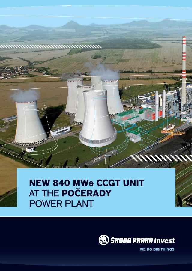
NEW 840 MWe CCGT UNITAT THE POČERADYPOWER PLANT

A WORD OF INTRODUCTION
WE DO BIG THINGS
The fact that ŠKODA PRAHA Invest is constructing the fi rst CCGT power plant in the Czech Republic in Počerady for the ČEZ Group attests to the important role of our Company as an advanced EPC contractor for power generation units and to our readiness to face these challenging projects.
The construction of this CCGT power plant is, without any doubt, an outstanding project both for us and for all participating contractors under our leadership. This new area of power engineering has a great future when con-sidering the growth in energy production from renewable sources and the increasing need to diversify production sources.
Ing. Daniel JiřičkaGeneral Director
ŠKODA PRAHA Invest
ABOUT THE LOCATION, ABOUT THE PROJECTABOUT THE LOCATION
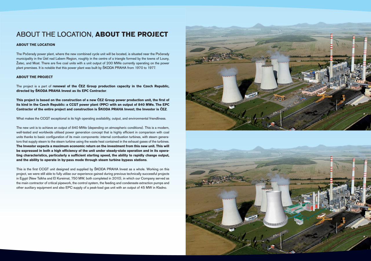
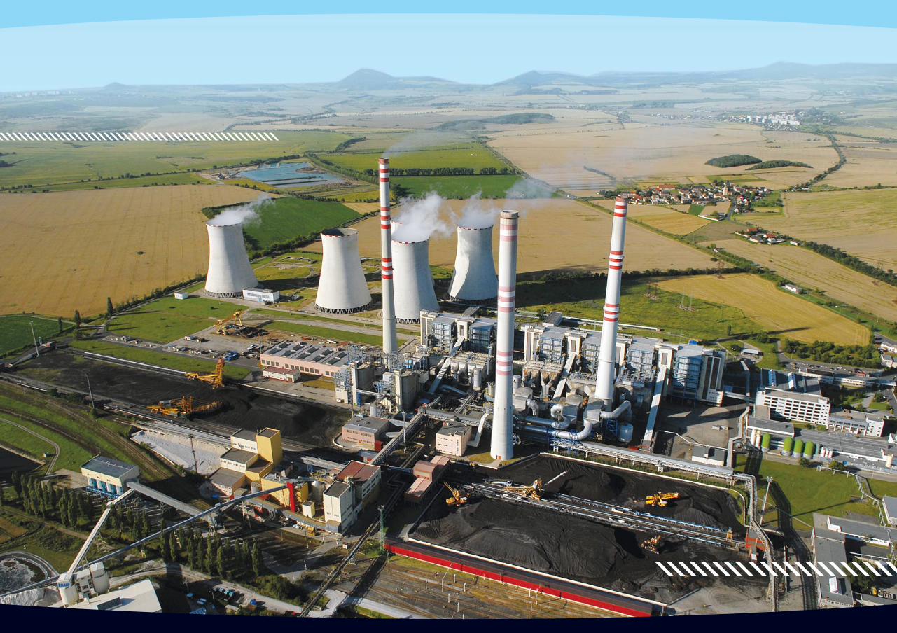
The Počerady power plant, where the new combined cycle unit will be located, is situated near the Počerady municipality in the Ústí nad Labem Region, roughly in the centre of a triangle formed by the towns of Louny, Žatec, and Most. There are fi ve coal units with a unit output of 200 MWe currently operating on the power plant premises. It is notable that this power plant was built by ŠKODA PRAHA from 1970 to 1977.
ABOUT THE PROJECT
The project is a part of renewal of the ČEZ Group production capacity in the Czech Republic, directed by ŠKODA PRAHA Invest as its EPC Contractor.
This project is based on the construction of a new ČEZ Group power production unit, the fi rst of its kind in the Czech Republic: a CCGT power plant (PPC) with an output of 840 MWe. The EPCContractor of the entire project and construction is ŠKODA PRAHA Invest; the Investor is ČEZ.
What makes the CCGT exceptional is its high operating availability, output, and environmental friendliness.
The new unit is to achieve an output of 840 MWe (depending on atmospheric conditions). This is a modern, well-tested and worldwide utilised power generation concept that is highly effi cient in comparison with coal units thanks to basic confi guration of its main components: internal combustion turbines, with steam genera-tors that supply steam to the steam turbine using the waste heat contained in the exhaust gases of the turbines. The Investor expects a maximum economic return on the investment from this new unit. This will be expressed in both a high effi ciency of the unit under steady-state operation and in its opera-ting characteristics, particularly a suffi cient starting speed, the ability to rapidly change output, and the ability to operate in by-pass mode through steam turbine bypass stations.
This is the fi rst CCGT unit designed and supplied by ŠKODA PRAHA Invest as a whole. Working on this project, we were still able to fully utilise our experience gained during previous technically successful projects in Egypt (New Talkha and El Kureimat, 750 MW, both completed in 2010), in which our Company served as the main contractor of critical pipework, the control system, the feeding and condensate extraction pumps and other auxiliary equipment and also EPC supply of a peak-load gas unit with an output of 45 MW in Kladno.
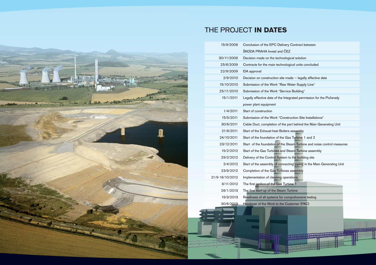
THE PROJECT IN DATES
15/9/2008 Conclusion of the EPC Delivery Contract between
ŠKODA PRAHA Invest and ČEZ
30/11/2008 Decision made on the technological solution
25/6/2009 Contracts for the main technological units concluded
22/9/2009 EIA approval
2/9/2010 Decision on construction site made — legally effective date
15/10/2010 Submission of the Work “Raw Water Supply Line“
25/11/2010 Submission of the Work “Service Building“
15/1/2011 Legally effective date of the Integrated permission for the Počerady
power plant equipment
1/4/2011 Start of construction
15/5/2011 Submission of the Work “Construction Site Installations“
30/6/2011 Cable Duct, completion of the part behind the Main Generating Unit
21/8/2011 Start of the Exhaust-heat Boilers assembly
24/10/2011 Start of the foundation of the Gas Turbine 1 and 2
23/12/2011 Start of the foundation of the Steam Turbine and noise control measures
15/2/2012 Start of the Gas Turbines and Steam Turbine assembly
29/2/2012 Delivery of the Control System to the building site
2/4/2012 Start of the assembly of connecting piping in the Main Generating Unit
23/8/2012 Completion of the Gas Turbines assembly
21/9-16/10/2012 Implementation of cleaning operations
8/11/2012 The fi rst ignition of the Gas Turbine 1
26/1/2013 The fi rst start-up of the Steam Turbine
19/3/2013 Readiness of all systems for comprehensive testing
30/6/2013 Handover of the Work to the Customer (PAC)
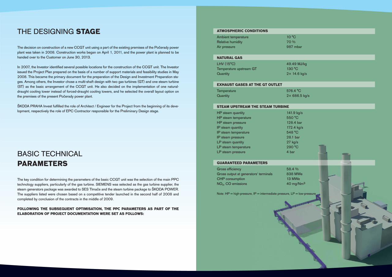
BASIC TECHNICALPARAMETERS
The key condition for determining the parameters of the basic CCGT unit was the selection of the main PPC technology suppliers, particularly of the gas turbine. SIEMENS was selected as the gas turbine supplier, the steam generators package was awarded to SES Tlmače and the steam turbine package to ŠKODA POWER. The suppliers listed were chosen based on a competitive tender launched in the second half of 2008 and completed by conclusion of the contracts in the middle of 2009.
FOLLOWING THE SUBSEQUENT OPTIMISATION, THE PPC PARAMETERS AS PART OF THE ELABORATION OF PROJECT DOCUMENTATION WERE SET AS FOLLOWS:
THE DESIGNING STAGE
The decision on construction of a new CCGT unit using a part of the existing premises of the Počerady power plant was taken in 2008. Construction works began on April 1, 2011, and the power plant is planned to be handed over to the Customer on June 30, 2013.
In 2007, the Investor identifi ed several possible locations for the construction of the CCGT unit. The Investor issued the Project Plan prepared on the basis of a number of support materials and feasibility studies in May 2008. This became the primary document for the preparation of the Design and Investment Preparation sta-ges. Among others, the Investor chose a multi-shaft design with two gas turbines (GT) and one steam turbine (ST) as the basic arrangement of the CCGT unit. He also decided on the implementation of one natural-draught cooling tower instead of forced-draught cooling towers, and he selected the overall layout option on the premises of the present Počerady power plant.
ŠKODA PRAHA Invest fulfi lled the role of Architect / Engineer for the Project from the beginning of its deve-lopment, respectively the role of EPC Contractor responsible for the Preliminary Design stage.
ATMOSPHERIC CONDITIONS
Ambient temperature 10 °C Relative humidity 70 %Air pressure 987 mbar
NATURAL GAS
LHV (15°C) 49.49 MJ/kgTemperature upstream GT 130 °C Quantity 2× 14.6 kg/s
EXHAUST GASES AT THE GT OUTLET
Temperature 576.4 °CQuantity 2× 686.5 kg/s
STEAM UPSTREAM THE STEAM TURBINE
HP steam quantity 141.9 kg/sHP steam temperature 550 °C HP steam pressure 128.4 barIP steam quantity 172.4 kg/sIP steam temperature 548 °C IP steam pressure 28.1 barLP steam quantity 27 kg/sLP steam temperature 290 °C LP steam pressure 4 bar
GUARANTEED PARAMETERS
Gross effi ciency 58.4 %Gross output at generators‘ terminals 838 MWeCHP consumption 13 MWeNOX, CO emissions 40 mg/Nm3
Note: HP = high-pressure, IP = intermediate pressure, LP = low-pressure
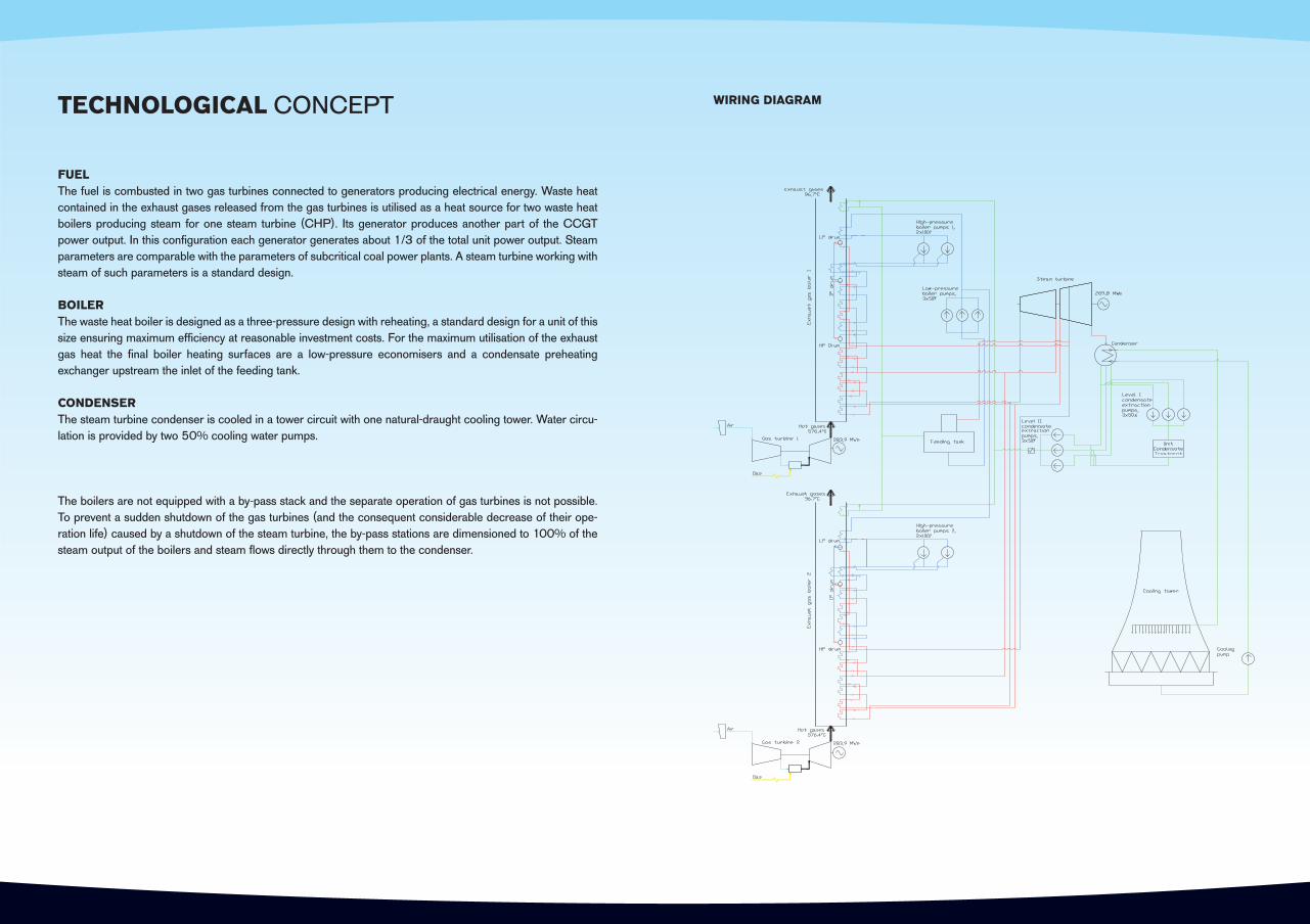
TECHNOLOGICAL CONCEPT
FUELThe fuel is combusted in two gas turbines connected to generators producing electrical energy. Waste heat contained in the exhaust gases released from the gas turbines is utilised as a heat source for two waste heat boilers producing steam for one steam turbine (CHP). Its generator produces another part of the CCGT power output. In this confi guration each generator generates about 1/3 of the total unit power output. Steam parameters are comparable with the parameters of subcritical coal power plants. A steam turbine working with steam of such parameters is a standard design.
BOILERThe waste heat boiler is designed as a three-pressure design with reheating, a standard design for a unit of this size ensuring maximum effi ciency at reasonable investment costs. For the maximum utilisation of the exhaust gas heat the fi nal boiler heating surfaces are a low-pressure economisers and a condensate preheating exchanger upstream the inlet of the feeding tank.
CONDENSERThe steam turbine condenser is cooled in a tower circuit with one natural-draught cooling tower. Water circu-lation is provided by two 50% cooling water pumps.
The boilers are not equipped with a by-pass stack and the separate operation of gas turbines is not possible. To prevent a sudden shutdown of the gas turbines (and the consequent considerable decrease of their ope-ration life) caused by a shutdown of the steam turbine, the by-pass stations are dimensioned to 100% of the steam output of the boilers and steam fl ows directly through them to the condenser.
WIRING DIAGRAM
MACHINERY PART
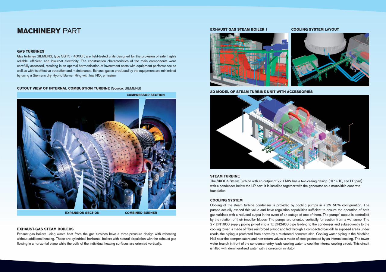
GAS TURBINESGas turbines SIEMENS, type SGT5 - 4000F, are fi eld-tested units designed for the provision of safe, highly reliable, effi cient, and low-cost electricity. The construction characteristics of the main components were carefully assessed, resulting in an optimal harmonisation of investment costs with equipment performance as well as with its effective operation and maintenance. Exhaust gases produced by the equipment are minimised by using a Siemens dry Hybrid Burner Ring with low NOx emission.
STEAM TURBINEThe ŠKODA Steam Turbine with an output of 270 MW has a two-casing design (HP + IP, and LP part) with a condenser below the LP part. It is installed together with the generator on a monolithic concrete foundation.
COOLING SYSTEMCooling of the steam turbine condenser is provided by cooling pumps in a 2× 50% confi guration. The pumps actually exceed this value and have regulation capabilities suffi cient to ensure the operation of both gas turbines with a reduced output in the event of an outage of one of them. The pumps' output is controlled by the rotation of their impeller blades. The pumps are oriented vertically for suction from a wet sump. The2× DN1800 supply piping joined into a 1x DN2400 pipe leading to the condenser and subsequently to the cooling tower is made of fi bre reinforced plastic and led through a compacted backfi ll. In exposed areas under roads, the piping is protected from above by a reinforced-concrete slab. Cooling water piping in the Machine Hall near the compensators and non-return valves is made of steel protected by an internal coating. The tower water branch in front of the condenser entry leads cooling water to cool the internal cooling circuit. This circuit is fi lled with demineralised water with a corrosion inhibitor.
EXHAUST-GAS STEAM BOILERSExhaust-gas boilers using waste heat from the gas turbines have a three-pressure design with reheating without additional heating. These are cylindrical horizontal boilers with natural circulation with the exhaust gas fl owing in a horizontal plane while the coils of the individual heating surfaces are oriented vertically.
COMPRESSOR SECTION
CUTOUT VIEW OF INTERNAL COMBUSTION TURBINE (Source: SIEMENS)
COMBINED BURNEREXPANSION SECTION
EXHAUST GAS STEAM BOILER 1 COOLING SYSTEM LAYOUT
3D MODEL OF STEAM TURBINE UNIT WITH ACCESSORIES

ELECTRICAL SYSTEMS, HOME CONSUMPTION
The system of the CCGT home consumption has operating, reserve, and emergency sources at its disposal. The transition between operating and reserve sources and the connection of emergency sources is performed automatically.
Operation of the CCGT home consumption system is provided by branch transformers powered by gas turbi-ne generator outlets. These branch transformers supply two independent sections of 6kV switchgear stations. Reserve supply of the 6kV switchgear stations is to be accomplished from the present common 6kV switch-gear for units 5 and 6 of the Počerady power plant. The emergency supply of secure power supply appli-ances, i.e. a power supply during the loss of both operating and reserve sources, is to be ensured from independent emergency sources - accumulator batteries and 0.4kV diesel-generator. The 6kV switchgears will supply the main 6kV drives and 6/0.42kV home consumption transformers for the technology and civil electrical installation. The majority of MV and LV switchgears are situated in four fl oors of a separate building designated for the control rooms and switchgears. Cable routes are led from the building cable area (-3.5 m level) around the Main Generating Unit.
The concept of cabling and cable routes complies with the PPC fi re safety solution and also includes inte-grated fi re resistant cable systems that retain their function in the event of fi re.
Note: MV = medium voltage, LV = low voltage
CONNECTION TO GRID
The electrical output of the PPC will be connected to the grid by a 400kV V468 line to the Výškov Switchgear.
The output of each PPC generator will be connected separately through the generator circuit breaker and its own output transformer into the corresponding array of the encased 400kV switchgear. The encased switch-gear utilises GIS (gas insulated switchgear) technology - SF6 gas insulation - and is located in a separate dedicated building near the line.
Connection of the generators to the output transformers is designed using encased cables including connecti-on to branch transformers and excitation transformers. Connection of the output transformers to the encased switchgear is realised by 400kV single-core cables. For these cables, a cable route is to be constructed directly adjacent the output transformer site and the encased switchgear building. The encased 400kVswitch-gear is equipped with three inlet arrays that will be fi tted with 400kV output circuit breakers which will ensure independence of the individual outlets in case of partial failure while at the same time enabling control of the CHP consumption generators. A disconnector is installed in the outlet array of the 400kV encased switchgear on the V468 line. The outside part of the 400kV switchgear includes a portal for connecting V468 line cables which constitutes the battery limit with the grid as a component of the PPC Work.
Both the outside and the encased part of the switchgear are equipped with instrument transformers for pro-tection, synchronisation, and measurement. Commercial and verifi cation measurement for invoicing is also provided there.
CONNECTION OF THE MAIN GENERATING UNIT BUILDINGSTO THE OUTPUT TRANSFORMERS
CONNECTION TO GRID
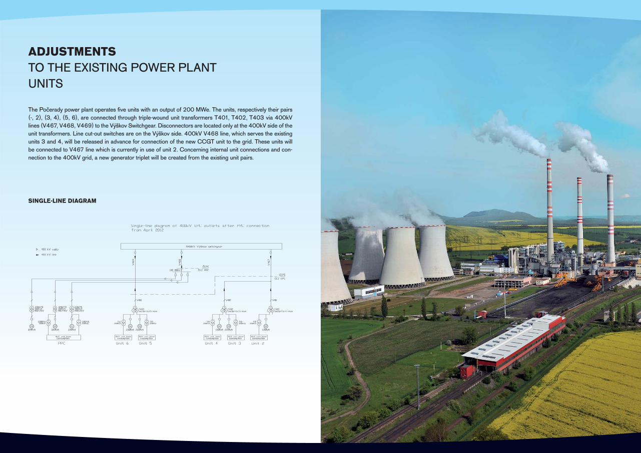
ADJUSTMENTSTO THE EXISTING POWER PLANTUNITS
The Počerady power plant operates fi ve units with an output of 200 MWe. The units, respectively their pairs (-, 2), (3, 4), (5, 6), are connected through triple-wound unit transformers T401, T402, T403 via 400kV lines (V467, V468, V469) to the Výškov Switchgear. Disconnectors are located only at the 400kV side of the unit transformers. Line cut-out switches are on the Výškov side. 400kV V468 line, which serves the existing units 3 and 4, will be released in advance for connection of the new CCGT unit to the grid. These units will be connected to V467 line which is currently in use of unit 2. Concerning internal unit connections and con-nection to the 400kV grid, a new generator triplet will be created from the existing unit pairs.
SINGLE-LINE DIAGRAM

TECHNOLOGY PROCESS CONTROL
The technology process control will be based on modern programmable equipment of a high industry stan-dard, communicating together through communication buses to ensure functionality, reliability, performance, resistance to environmental infl uences and quality assurance requirements.
The automatic technology process control system will allow the listing of the event sequence during break-downs, long-term archiving of measured technological process values, process equipment diagnostics, and other support functions.
A unifi ed distributed control system connected to autonomous control systems for gas turbines, steam turbine, and a chemical water treatment plant will be used for PPC technology control as a whole. With these linked systems, the control system is designed to constitute one integrated system able to optimally and automatically control the Main Generating Unit and other power plant technology nodes both during stable and transient operating conditions.
The individual systems will be connected at the level of automation and application buses, through HW sig-nals, and via communication connections. The critical components of the system and its power supply will be redundant to achieve high operational system reliability. Standard protection methods will be implemented to protect the control system against external attack. To ensure high operation safety, the part of the control system and protection circuits will be produced with the required security level to ensure the reliability of security functions.
deliv
ered
by
E F
PR
deliv
ered
by
E F
PR
deliv
ered
by
E F
PR
V
PN
Tun
nel
Con
nect
ion
to th
ird p
arty
sys
tem
to
be
clar
ified
App
licat
ion
Hig
hway
Oth
er S
uppl
ier
xxx
ST
Aut
omat
ion
Hig
hway
Opt
iona
l: Pe
rfor
man
ceM
onito
ring
TC
Shift
Sup
ervi
sor
TC
His
toria
n / E
ngin
eerin
g
TC
Col
or L
aser
Prin
ter
Opt
ion
:Pe
rfor
man
ce M
onito
ring
Serv
er
Cen
tral C
ontro
l Roo
m -
CC
R
Ele
ctric
al
Are
a
Wat
er
Trea
tmen
tA
rea
HR
SG
Are
a
CM
104
CM
104
CM
104
Non
Red
unda
nt S
eria
l Lin
k:M
V S
witc
hgea
r PR
OFI
BU
SS
witc
hyar
d IE
C 6
1850
Lin
kC
isco
Lin
kC
EM
S (M
OD
BU
S –
TC
P/IP
)…
Red
unda
nt S
eria
l Lin
k:PS
09
Elec
trica
lsPS
10
APC
S PS
12
Com
pres
sor s
tatio
nPS
06,
16,
18
CH
UV
PS 2
1 M
odifi
catio
ns in
the
exis
ting
bloc
ksC
entra
l Dis
patc
h, P
TIS,
DAM
ATIC
, Č
EPS
Scope by Siemens
Scope by others
BO
P / T
CS
Ope
rato
r
TC52''
Ele
ctric
al B
uild
ing
SPPA
-T30
00A
uS (r
ed)
SPPA
-T30
00A
uS (r
ed)
SPPA
-T30
00A
uS (r
ed)
RA
ID
BO
P / T
CS
Ope
rato
r
TC52''
BO
P / T
CS
Ope
rato
r
TC
SPPA
-T30
00
Dat
a lo
gger
Turb
ine
cont
rol
Turb
ine
gove
rno
Fast
I/O
mod
ule
AuS
(red
)Sp
ecia
l Sys
tem
s
I/O m
odul
es
Flam
e m
onito
rin
Spee
d m
onito
rin
Turb
ine
Trip
Sy
AuS
(red
)SP
ecia
l Mea
ssur
Wob
be
AR
GU
S
AR
GU
S
AuS
(red
)ET
200
I/O m
odul
es
I/O m
odul
es
I/O m
odul
es
I/O m
odul
es
ET20
0
I/O m
odul
es
I/O m
odul
es
I/O m
odul
es
SPPA
-T30
00
I/O
Cab
inet
SPPA
-T30
00
I/O
Cab
inet
2x2x
2x
SPPA
-T30
00
I/O
Cab
inet
G1C
JT01
SFC
G1C
JT01
SEE
SPPA
-T30
00
Dat
a lo
gger
Turb
ine
cont
rol
Turb
ine
gove
rno
Fast
I/O
mod
ule
AuS
(red
)Sp
ecia
l Sys
tem
s
I/O m
odul
es
Flam
e m
onito
rin
Spee
d m
onito
rin
Turb
ine
Trip
Sy
AuS
(red
)SP
ecia
l Mea
ssur
Wob
be
AR
GU
S
AR
GU
S
AuS
(red
)ET
200
I/O m
odul
es
I/O m
odul
es
I/O m
odul
es
I/O m
odul
es
ET20
0
I/O m
odul
es
I/O m
odul
es
I/O m
odul
es
M
Fiel
d D
evic
es
G1C
JT01
SEE
Profibus
M
Fiel
d D
evic
esG
T G
2
M
Fiel
d D
evic
esG
T G
1
xxx
ST
M
Fiel
d D
evic
esST
Gas
Tur
bine
1S
team
Tur
bine
HW
HW
HW
HW
HW
HW
ACC
S
OT
xxx
ST
CM
104
CM
104 to c
larif
y
ApS
(red
)
Pow
er C
ontro
l Cen
ter -
PC
CP
ower
Con
trol C
ente
r -P
CC
Profibus
G1U
BA0
1G
2UBA
01
Fire
wal
l
GP
SG
PS
WIN
-TS
TC
Dem
ilita
rized
Zo
ne
Terminal Server
Fire
wal
l
SIE
ME
NS
Rem
ote-
Ser
vice
Dat
a Se
rver
Firewall
Acc
ess
Serv
er
G1U
BA02
G2U
BA0
2
Gas
Tur
bine
2
Rou
ter
WIN
-TS
LAN
WIN
-TS
LAN
BW
Las
er P
rinte
rA
larm
Prin
ter
Larg
e Sc
reen
py
g
Plan
tM
anag
emen
t Sy
stem
Opt
iona
l:
Firewall
OT
ApS
OT
OT
ApS
Rou
ter
Rou
ter
CONTROL SYSTEM ARCHITECTURE

CIVIL PART
The architectural and civil layout design has been determined by technological requirements and complies with noise protection and fi re safety requirements as well as with environmental limits.
THE CRITICAL CIVIL STRUCTURES ARE:· The Main Generating Unit (Machine Halls for Steam and Internal Combustion Turbines)· The Natural-Draught Cooling Tower· The Cooling Water Pumping Station and the Fire Fighting Water Pumping Station· The Encased Switchgear Building· The Make-up Water Treatment Plant
The Boiler House, Machine Halls for Steam and Internal Combustion Turbines, Control Rooms, Switchgears, Compressor Station and piping areas objects constitute a structurally single compact Main Generating Unit.The Main Generating Unit layout is composed of individual operating parts, its main dimensions being approx. 151.1 x 82.6 m. The individual parts of the Main Generating Unit are placed at different heights. The total built-up area is 8,367 m2 (excluding stack foundations and cooling pits). Foundations, footings, underground areas and ducts will be constructed of reinforced-concrete; above-ground structures will be made of steel.There are underground cable areas below the switchgears under part of the Main Generating Unit. The space is composed of a concrete sump upon which the structure of control rooms is founded. The foundation is shal-low, composed of a foundation slab, the cable space ceiling is a slab-and-girder monolithic type in accordance with the requirements for fl oor openings and it is supported by concrete pillars.
COOLING TOWER STEAM TURBINE MACHINE HALLGAS TURBINE
MACHINE HALLS
COOLING AND FIRE FIGHTINGWATER PUMPING STATIONS ADMINISTRATION BUILDING EXHAUST-GAS BOILERS
LAYOUT GROUND PLAN
VIEW OF THE MAIN GENERATING UNIT, COOLING WATER PUMPING STATION,AND COOLING TOWER FROM THE NORTH
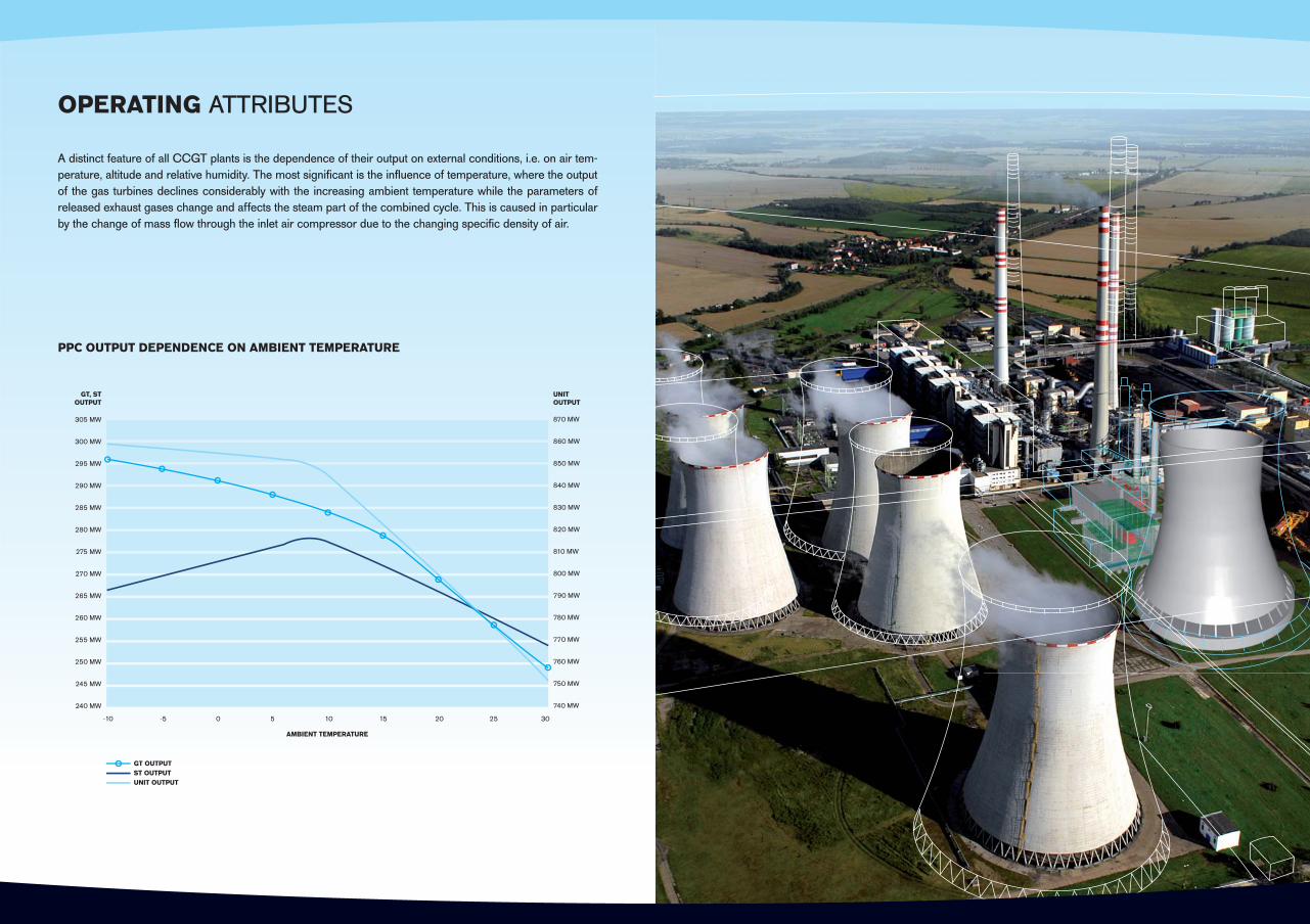
OPERATING ATTRIBUTES
A distinct feature of all CCGT plants is the dependence of their output on external conditions, i.e. on air tem-perature, altitude and relative humidity. The most signifi cant is the infl uence of temperature, where the output of the gas turbines declines considerably with the increasing ambient temperature while the parameters of released exhaust gases change and affects the steam part of the combined cycle. This is caused in particular by the change of mass fl ow through the inlet air compressor due to the changing specifi c density of air.
PPC OUTPUT DEPENDENCE ON AMBIENT TEMPERATURE
305 MW
300 MW
295 MW
290 MW
285 MW
280 MW
275 MW
270 MW
265 MW
260 MW
255 MW
250 MW
245 MW
240 MW
870 MW
860 MW
850 MW
840 MW
830 MW
820 MW
810 MW
800 MW
790 MW
780 MW
770 MW
760 MW
750 MW
740 MW
GT, STOUTPUT
UNITOUTPUT
AMBIENT TEMPERATURE
-10 -5 0 5 10 15 20 25 30
GT OUTPUTST OUTPUTUNIT OUTPUT

WE ARE AN EPC CONTRACTOR AND DEVELOPER OF INVESTMENT PROJECTS IN THE ENERGY SECTOR
We are the largest Czech engineering contractor able to deliver power generation projects from the design through implementation and assembly to commissioning and securing of both warranty and extended warranty service. We also supply balance of plant. We provide service tasks.
We are active primarily in conventional and nuclear power, but also in heating plants, CCGT power plants and renewable energy sectors.
We are implementing the Czech industrial project of the decade, the Renewal of the ČEZ Group productioncapacity. As part of this project we are performing the comprehensive and environmentally benefi cial renewal of the Tušimice II and Prunéřov II power plants; we are constructing a new production unit with supercritical steam parameters in the Ledvice power plant and a new CCGT plant in the Počerady power plant. We are also implementing complex delivery projects for nuclear power plants as well as output improvement projects and nuclear unit modernisation. We also operate in the fi eld of renewable energy sources.
We excel in a strong professional know-how that we have been building under the ŠKODA PRAHA trademark for 60 years. During that time, we have delivered more than one hundred power generation units with a total output of 40,000 MW to 25 countries around the world. We deliver energy generation works that stand out due to their high technological quality, effi ciency, reliability, and are environmentally friendly.
VISIONIS THE FIRST STEPTO ACTION
WE DO BIG THINGS

NEW 840 MWe CCGT UNITAT THE POČERADY POWER PLANT
APRIL 1, 2011
WE DO BIG THINGS
www.spinvest.cz