Embed Size (px)
Citation preview

Neutron irradiation effects on domain wall mobility and reversibility in lead zirconatetitanate thin filmsJoseph T. Graham, Geoff L. Brennecka, Paulo Ferreira, Leo Small, David Duquette, Christopher Apblett,
Sheldon Landsberger, and Jon F. Ihlefeld Citation: Journal of Applied Physics 113, 124104 (2013); doi: 10.1063/1.4795869 View online: http://dx.doi.org/10.1063/1.4795869 View Table of Contents: http://scitation.aip.org/content/aip/journal/jap/113/12?ver=pdfcov Published by the AIP Publishing Advertisement:
[This article is copyrighted as indicated in the abstract. Reuse of AIP content is subject to the terms at: http://scitation.aip.org/termsconditions. Downloaded to ] IP:
146.6.84.63 On: Wed, 23 Oct 2013 17:34:29

Neutron irradiation effects on domain wall mobility and reversibility in leadzirconate titanate thin films
Joseph T. Graham,1,2,a) Geoff L. Brennecka,2 Paulo Ferreira,3 Leo Small,2,4
David Duquette,4 Christopher Apblett,5 Sheldon Landsberger,1 and Jon F. Ihlefeld2,b)
1The Nuclear Engineering Teaching Laboratory, The University of Texas at Austin, Austin, Texas 78758, USA2Electronic, Optic and Nano Materials Department, Sandia National Laboratories, Albuquerque,New Mexico 87185, USA3Materials Science and Engineering Program, The University of Texas at Austin, Austin, Texas 78751, USA4Department of Materials Science and Engineering, Rensselaer Polytechnic Institute, Troy,New York 12180, USA5Advanced Power Sources R&D Department, Sandia National Laboratories, Albuquerque,New Mexico 87185, USA
(Received 29 October 2012; accepted 4 January 2013; published online 28 March 2013)
The effects of neutron-induced damage on the ferroelectric properties of thin film lead zirconate
titanate (PZT) were investigated. Two sets of PbZr0:52Ti0:48O3 films of varying initial quality were
irradiated in a research nuclear reactor up to a maximum 1 MeV equivalent neutron fluence of
(5.16 6 0.03)� 1015 cm�2. Changes in domain wall mobility and reversibility were characterized by
polarization-electric field measurements, Rayleigh analysis, and analysis of first order reversal
curves (FORC). With increasing fluence, extrinsic contributions to the small-signal permittivity
diminished. Additionally, redistribution of irreversible hysterons towards higher coercive fields was
observed accompanied by the formation of a secondary hysteron peak following exposure to high
fluence levels. The changes are attributed to the radiation-induced formation of defect dipoles and
other charged defects, which serve as effective domain wall pinning sites. Differences in damage
accumulation rates with initial film quality were observed between the film sets suggesting a
dominance of pre-irradiation microstructure on changes in macroscopic switching behavior. VC 2013American Institute of Physics. [http://dx.doi.org/10.1063/1.4795869]
I. INTRODUCTION
The role(s) of defects on ferroelectric behavior in lead
zirconate titanate (PZT) ceramics and thin films is of interest
because of their strong influence on extrinsic properties.
Neutron irradiation is a means of introducing crystallographic
defects in a material in a controlled manner. In nuclear reac-
tor environments, exposure to energetic neutrons can dramati-
cally alter the performance of a material as neutrons are
highly penetrating and capable of bringing about irreversible
microstructural changes.1 Damage accumulates when fast
neutrons undergo scattering collisions with atomic nuclei
resulting in localized displacement cascades. The subsequent
interaction of mobile and immobile defect species produced
in the cascades — such as vacancies, self-interstitial atoms
(SIAs), and point defect clusters — control the microstruc-
tural evolution.2 Interest in radiation effects in PZT thin films
also stems from memory and sensing applications in satellite
and nuclear power technology where radiation damage may
determine the total device lifetime.3
Charged defects influence ferroelectric behavior by acting
as pinning sites that impede domain wall motion.4 Point defect
complexes that form defect dipoles (DDs) are known to be an
important class of charged defects.5–7 In PZT ceramics,
mobile oxygen vacancies associate with substitutional
acceptor impurities to form DDs of the A0B � V••O and A00B � V••
O
types.5,8 These DDs are largely responsible for the hardness of
acceptor-doped PZT. In contrast, low mobility type DDs such
as V00Pb � D••Ti in soft PZT lower the oxygen vacancy concen-
tration and increase domain wall mobility. In ambient temper-
ature, radiation-free environments, the equilibrium population
of DDs reflects chemical composition and processing condi-
tions. Vacancy concentration is naturally dictated by a number
of mechanisms such as charge compensation of impurity/
dopant atoms, grain growth, crystallization temperature,
unbalanced ionic volatility, and substrate interactions to name
a few. In irradiated materials, however, there is a process inde-
pendent source of vacancies, SIAs and defect clusters. The
concentrations of such defect species primarily depend on
dose, irradiation temperature, and defect reactions. That
said, microstructure plays a critical role in damage evolution
and subsequent changes in material properties. Indeed, com-
parison of previous studies on neutron effects in PZT indicates
roughly an order of magnitude lower damage thresholds in
thin film compared to bulk.9–11 It should be noted as well that
greater defect concentrations and lower overall crystal quality
have been identified as likely candidates for the generally
observed inferior properties of thin films relative to their bulk
counterparts.12–14 It is expected that a wider variety of DDs
and other charged defects may form in irradiated PZT than
occur during typical processing, providing a broader land-
scape of domain wall pinning sites and other possible effects
a)Electronic mail: [email protected])Author to whom correspondence should be addressed. Electronic mail:
0021-8979/2013/113(12)/124104/9/$30.00 VC 2013 American Institute of Physics113, 124104-1
JOURNAL OF APPLIED PHYSICS 113, 124104 (2013)
[This article is copyrighted as indicated in the abstract. Reuse of AIP content is subject to the terms at: http://scitation.aip.org/termsconditions. Downloaded to ] IP:
146.6.84.63 On: Wed, 23 Oct 2013 17:34:29

on switching behavior. Furthermore, material irradiations are
a useful means for controlled examination of the interactions
among point defects (PDs), microstructure, and changes in
material properties.
Domain wall motion and domain switching may be inves-
tigated with first order reversal curves (FORC).15 Quantitative
analysis of FORC measurements can be framed in terms of
the Preisach model, which assumes that a ferroelectric mate-
rial can be described as an ensemble of hysterons, elementary
units of hysteresis that exhibit a perfect square polarization-
electric field (PE) loop.16 Each hysteron takes on a positive or
negative unit response and is characterized by an up-switching
field a and a down-switching field b. Under the conditions of
congruency and deletion, the hysteron density function is
referred to as the Preisach function;15 under more relaxed
assumptions, the FORC label is applied.
The utility of the FORC concept is that FORC can be eas-
ily measured. Graphical representations of their associated
hysteron density functions are valuable tools for visualizing
reversible and irreversible contributions and the influence of
defects and other properties on switching behavior. FORC has
been successfully applied to studying the effects of dopants,
film thickness, fatigue and porosity in PZT thin films.13,17–19
In the regime of low bias, domain wall restructuring is
minimal and domain wall contributions to the dielectric
permittivity are largely determined by local domain wall
motion.20 Non-linear dielectric response is a consequence of
reversible and irreversible motion across a (presumably) ran-
dom field of domain pinning sites. Under low amplitude
applied AC fields, the domain walls oscillate between pin-
ning sites in a reversible manner. At higher amplitude fields,
the domain walls may be moved across pinning sites result-
ing in irreversible domain wall motion. Reversible and irre-
versible motion contributes to non-linear dielectric behavior
as described by the Rayleigh relation.
�0 ¼ �0init þ a0E0: (1)
�0 is the real component of permittivity, �0init is the con-
tribution of intrinsic permittivity and reversible domain wall
motion, a0 is the irreversible Rayleigh parameter, and E0 is
the amplitude of the applied AC field. Note that a0 here is
different from the a switching field appearing in FORC.
Measurement of the Rayleigh parameters has been used
extensively to characterize domain wall dynamics in poly-
crystalline ceramics, single crystals, polycrystalline thin
films, and epitaxial thin film ferroelectrics.21–31
The Rayleigh relation is only valid when the effects of
domain wall-domain wall interactions and saturation are
negligible.20 This is the case for applied fields well below
the coercive field (typically less than 0.5 Ec). Above this so-
called Rayleigh regime, higher order non-linear terms begin
to influence the permittivity and FORC is a more useful tool
for examining domain switching.18,32
II. EXPERIMENTAL PROCEDURE
The samples used in this study were diced from 75 mm
diameter platinized silicon wafers coated with 320 and
350 nm thick PZT 52/48 films prepared by a chemical solu-
tion deposition (CSD) method.33,34 The 320 nm films were
prepared from a 0.4 molar Inverse Mixing Order (IMO)35
solution chemistry with 20% excess PbO and the 350 nm
films were prepared with a 0.35 molar solution with 25%
excess PbO. Each solution was spin cast in four layers onto
a 300 lm thick commercial Pt/Ti/SiO2/Si substrate (170 nm
Pt, 40 nm Ti, 400 nm SiO2, and 300 lm Si) from vendor
Silicon Quest International. The 320 nm films were pyro-
lyzed at 300 �C for 1 min after deposition of each layer while
the 350 nm films were pyrolyzed at 350 �C for 1 min. After
deposition of the fourth and final layer, both films were crys-
tallized at 700 �C for 10 min. Apart from the stoichiometry
and pyrolysis temperature, the processing conditions for
each film were nominally equivalent. The 320 and 350 nm
films will be referred to as sets A and B, respectively,
throughout this manuscript. Samples were diced prior to
irradiation. Post irradiation platinum top electrodes were
deposited by RF magnetron sputtering through a shadow
mask. The resulting electrode areas were determined via
optical microscopy and IMAGEJ image processing software.
The films were irradiated in the TRIGA mark II research
nuclear reactor at the University of Texas at Austin in an in-
core Rotary Specimen Rack (RSR). The RSR consists of a
rotating annular rack with 40 vial slots. The RSR encircles
the fuel assembly and it is encased on its outer surface by a
graphite neutron reflector.36 Samples were equally spaced in
the rack slots to minimize inhomogeneities in neutron self-
shielding. During the irradiation, the RSR was rotated at
2 rpm to ensure uniform time-averaged flux. The irradiations
were performed at a 1 MeV equivalent neutron flux of
(7.17 6 0.04)� 1011 cm�2 s�1 (950kWth reactor power) for
durations of 15, 30, and 120 minutes (set A) and 30, 60, and
120 min (set B) under ambient temperature and atmospheric
conditions. A control sample from each wafer was left un-
irradiated for comparison. All measurements were performed
post-irradiation.
Domain wall mobility in the Rayleigh regime was inves-
tigated by measuring capacitance at applied AC fields from
0.2 to 16:2 kV cm�1 (measured peak-to-peak) and frequen-
cies from 1 to 100 kHz with a Hewlett Packard 4192 A
impedance analyzer. The Rayleigh measurements were made
prior to all other electronic measurements to avoid domain
restructuring which occurs at high fields. Nested 1 kHz PE
loops were measured up to a field amplitude of 313 kV cm�1
for set A and 1113 kV cm�1 for set B using a Radiant
Precision Workstation to identify changes in polarization
reversal characteristics. For each loop, a sequence of two
delayed bipolar voltage signals was applied to the electrode.
The first bipolar signal pre-poles the PZT, placing it in a neg-
atively polarized state. The polarization measurement is
made with the second signal. Lower maximum field ampli-
tude was applied to set A because those samples were
observed to undergo dielectric breakdown at lower fields.
FORC measurements were taken using a Radiant
Precision Workstation. The films were initially pre-poled to
�283 kV cm�1. Then a sequence of 39 biased, monopolar,
triangle voltage pulses was applied and the polarization
response measured. Typical FORC data are shown in
124104-2 Graham et al. J. Appl. Phys. 113, 124104 (2013)
[This article is copyrighted as indicated in the abstract. Reuse of AIP content is subject to the terms at: http://scitation.aip.org/termsconditions. Downloaded to ] IP:
146.6.84.63 On: Wed, 23 Oct 2013 17:34:29

Figure 1. The pulse width was 10 ms, the time between
pulses was 1 s during which the films were re-poled at
�283 kV cm�1. Subsequent pulse maxima increased in
0.5 V increments corresponding to a final measurement range
of �271 to þ271 kV cm�1 in 14:3 kV cm�1 increments.
The FORC were calculated by subtracting the polarization
on each descending branch Pa!b from the polarization at the
reversal points Pa.
Fða; bÞ ¼ Pa � Pa!b: (2)
In order to avoid resolution bias, the data were binned
into 14:3 kV cm�1 width bins, the coarsest resolution of the
measurement. The hysteron density lða; bÞ is given by the
mixed partial derivative of Fða; bÞ.
lða; bÞ ¼ � @2Fða; bÞ@a@b
: (3)
The above derivative was calculated numerically using
a forward differencing scheme and a step size equal to the
data bin width.
For the capacitance and FORC measurements, between
11 and 15 electrodes were measured per neutron dose level
to account for electrode-electrode variance which might oth-
erwise be erroneously attributed to radiation effects.
Secondary electron Scanning Electron Microscope (SEM)
images of set A films revealed a high concentration of surface
fluorite, and an average perovskite grain diameter of 125
6 8 nm (Fig. 2). The surface fluorite appears as lighter, fine-
grained patches. In contrast, set B had low concentrations
of surface fluorite and an average perovskite grain diameter
of 120 6 13 nm (Fig. 3). Grain diameters were determined
via particle area measurements taken with IMAGEJ according
to ASTM-E112. Cross-sectional micrographs (not shown)
revealed high density, columnar grain morphologies in both
film sets. Grazing incidence Cu Ka X-Ray Diffraction (XRD)
measurements indicate that the films are single phase and pol-
ycrystalline with predominantly (100) and (111) oriented
grains (Fig. 4). It should be mentioned that grain size, texture
and morphology were not noticeably altered at these doses, as
we would expect.
III. RESULTS AND DISCUSSION
The set A samples exhibited a noted decrease in polar-
ization with increasing fluence with representative hysteresis
loops shown in Figure 5. Average remanent polarization, Pr,
and coercive field, Ec, values that were calculated over meas-
urements of several electrodes appear as text insets in the
figure. Each reported value represents the average of the
magnitudes of the positive and negative remanent polariza-
tion or coercive field. The positive coercive field was
inferred by linearly extrapolating a portion of the ascending
curve to zero polarization. This was done to help eliminate
the effect of the loop discontinuity; an artifact of leakage
FIG. 1. Representative FORC data for set B films irradiated at fluence: con-
trol (a), 1.3� 1015 cm�2 (b), 2.6� 1015 cm�2 (c), 5.2� 1015 cm�2 (d).
FIG. 2. SEM plan view micrographs of PZT film set A at neutron fluence:
control (a), 0.7� 1015 cm�2 (b), 1.3� 1015 cm�2 (c), 5.2� 1015 cm�2 (d).
The fine grained regions are surface fluorite.
FIG. 3. SEM plan view micrographs of PZT film set B at neutron fluence:
control (a), 1.3� 1015 cm�2 (b), 2.6� 1015 cm�2 (c), 5.2� 1015 cm�2 (d).
124104-3 Graham et al. J. Appl. Phys. 113, 124104 (2013)
[This article is copyrighted as indicated in the abstract. Reuse of AIP content is subject to the terms at: http://scitation.aip.org/termsconditions. Downloaded to ] IP:
146.6.84.63 On: Wed, 23 Oct 2013 17:34:29
after the pre-poling stage of the measurement. No statisti-
cally significant changes in the coercive field were observed.
These observations are consistent with those of other authors
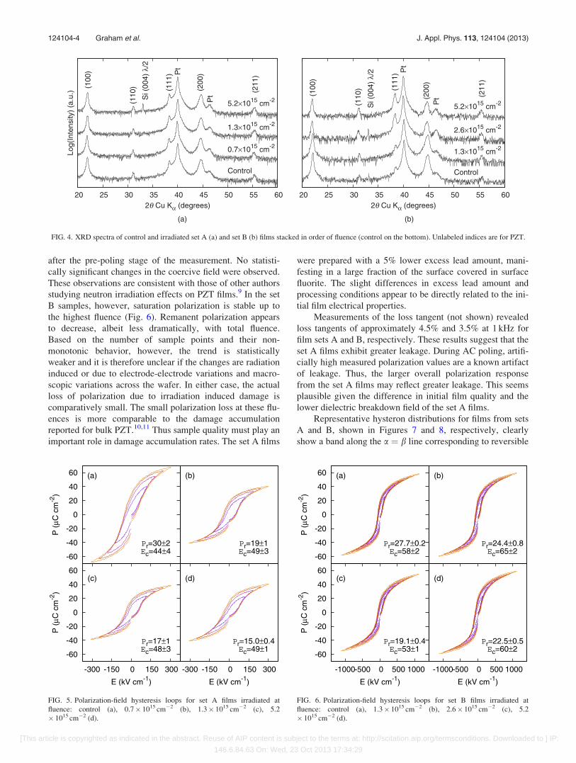
studying neutron irradiation effects on PZT films.9 In the set
B samples, however, saturation polarization is stable up to
the highest fluence (Fig. 6). Remanent polarization appears
to decrease, albeit less dramatically, with total fluence.
Based on the number of sample points and their non-
monotonic behavior, however, the trend is statistically
weaker and it is therefore unclear if the changes are radiation
induced or due to electrode-electrode variations and macro-
scopic variations across the wafer. In either case, the actual
loss of polarization due to irradiation induced damage is
comparatively small. The small polarization loss at these flu-
ences is more comparable to the damage accumulation
reported for bulk PZT.10,11 Thus sample quality must play an
important role in damage accumulation rates. The set A films
were prepared with a 5% lower excess lead amount, mani-
festing in a large fraction of the surface covered in surface
fluorite. The slight differences in excess lead amount and
processing conditions appear to be directly related to the ini-
tial film electrical properties.
Measurements of the loss tangent (not shown) revealed
loss tangents of approximately 4.5% and 3.5% at 1 kHz for
film sets A and B, respectively. These results suggest that the
set A films exhibit greater leakage. During AC poling, artifi-
cially high measured polarization values are a known artifact
of leakage. Thus, the larger overall polarization response
from the set A films may reflect greater leakage. This seems
plausible given the difference in initial film quality and the
lower dielectric breakdown field of the set A films.
Representative hysteron distributions for films from sets
A and B, shown in Figures 7 and 8, respectively, clearly
show a band along the a ¼ b line corresponding to reversible
FIG. 4. XRD spectra of control and irradiated set A (a) and set B (b) films stacked in order of fluence (control on the bottom). Unlabeled indices are for PZT.
FIG. 5. Polarization-field hysteresis loops for set A films irradiated at
fluence: control (a), 0.7� 1015 cm�2 (b), 1.3� 1015 cm�2 (c), 5.2
� 1015 cm�2 (d).
FIG. 6. Polarization-field hysteresis loops for set B films irradiated at
fluence: control (a), 1.3� 1015 cm�2 (b), 2.6� 1015 cm�2 (c), 5.2
� 1015 cm�2 (d).
124104-4 Graham et al. J. Appl. Phys. 113, 124104 (2013)
[This article is copyrighted as indicated in the abstract. Reuse of AIP content is subject to the terms at: http://scitation.aip.org/termsconditions. Downloaded to ] IP:
146.6.84.63 On: Wed, 23 Oct 2013 17:34:29

contributions as well as a strong peak associated with irre-
versible contributions in the lower right quadrant. The first
notable trend is that this peak decays and broadens with
increasing fluence. Given that the saturation polarization
does not similarly decay in set B, the total integrated vol-
umes under the hysteron distributions are approximately
equal. Thus, the number of hysterons is mostly conserved for
that film set and the observed changes in the hysteron density
can be described as redistribution. In contrast, the drop in
polarization for the set A films implies that the change in
hysteron densities can either be interpreted as hysteron
extinction or otherwise as a significant redistribution of hys-
terons to fields in excess of 313 kV cm�1 (the measurable
field range for the set A film).
Figure 9 shows the integrated reversible bands for each
set of films. This band represents the hysteron density under
the a ¼ b line as a function of the up-switching field a. The
integration was performed over 3 bin widths (3ffiffiffi
2p
bin widths
in the a ¼ �b direction). Integrating over this range was
sufficient for capturing the majority of the reversible hyster-
ons while minimizing the irreversible hysteron overlap. At
low bias, the two films exhibit different behaviors. The re-
versible contribution of film set A drops steadily with fluence
while only small changes are seen in film set B. This sug-
gests that for film set B, redistribution of hysterons in the
irreversible sector of the plane primarily occurs by the trans-
fer of hysterons to higher magnitude field values (i.e., large
absolute values of a and b) while in film set A, hysteron
extinction in the reversible sector also occurs. Importantly,
the tails of the reversible curves do not vary significantly
with fluence. At these tails, the bias field is large and most of
the mobile domain walls are driven out of the grains. Thus
the extrinsic contribution is negligible and the value reflects
intrinsic contributions only. This data indicate that the intrin-
sic permittivity values are the same for both films (as
expected for PZT films of the same composition) and that
the changes that occur at low bias fields are entirely extrinsic
in nature (i.e., due to changes in reversible domain wall
motion). The difference in peak height between sets A and B
films is significant. It could reflect either a difference in the
amount of reversible behavior and/or artifacts from the
higher leakage in set A films. As mentioned before, loss tan-
gent measurements indicate greater conductivity (and there-
fore leakage) in the set A films. Domain wall density and
pinning strength, however, also influence the low field
reversibility. Indeed, the difference in peak shape — with
the set A films being more peaked — is an indication that the
domain dynamics are different. More subtly, leakage and do-
main wall pinning are expected to be interrelated. Charged
defects may act both as pinning sites for domain walls and
traps for mobile charge carriers. The concentrations and
energy levels associated with carrier traps influence carrier
mobility (and therefore leakage). In either case, greater sig-
nificance is attached to the relative changes in hysteron den-
sities than to absolute differences in values between film sets
A and B.
Another feature apparent in the FORC analysis is the
presence of imprint. The majority of hysterons have an up-
switching field at a¼ 80 kV cm�1 and a down-switching
field of b¼�30 kV cm�1 implying that there is a negative
built-in bias field with respect to the polarity of the measure-
ment (top electrode at the high potential). At the highest flu-
ence, there is also the formation of a second peak. The peak
is faintly visible in set A and notable in set B. The two peaks
are separated by a field of 76 kV cm�1. The double peak is
characteristic of localized built-in fields such as those caused
by DDs. Over long time scales DDs can align with the spon-
taneous polarization by thermal migration whereas on the
time scales that the FORC measurements are performed,
DDs are essentially frozen in place. In an otherwise purely
intrinsic ferroelectric, the DDs oriented with the direction of
the applied field stabilize domains with spontaneous polar-
izations also in the direction of the applied field (Figure 10).
In the figure, the slab represents a region of ferroelectric ma-
terial. DDs (blue ovals) are oriented with the initial domain
structure along the directions of spontaneous polarization (of
which there are two in subfigure I). In this schematic, the
DDs are the only extrinsic feature. The corresponding points
FIG. 7. Hysteron densities for set A films irradiated at fluence: control (a),
0.7� 1015 cm�2 (b), 1.3� 1015 cm�2 (c), 5.2� 1015 cm�2 (d).
FIG. 8. Hysteron densities for set B films irradiated at fluence: control (a),
1.3� 1015 cm�2 (b), 2.6� 1015 cm�2 (c), 5.2� 1015 cm�2 (d).
124104-5 Graham et al. J. Appl. Phys. 113, 124104 (2013)
[This article is copyrighted as indicated in the abstract. Reuse of AIP content is subject to the terms at: http://scitation.aip.org/termsconditions. Downloaded to ] IP:
146.6.84.63 On: Wed, 23 Oct 2013 17:34:29

on the PE loop are shown at the bottom of the figure. The
black arrows represent the local electric field due to the com-
bined effects of the ferroelectric polarization, the DDs and
the applied electric field, while the grey walls indicate do-
main walls and the red arrows correspond to the applied elec-
tric field. As indicated, the DDs create local bias regions that
parallel the initial domain structure. In the initially unpoled
slab, the bias regions reinforce the domain structure (I). As
the external field is varied, however, the bias regions shift
the local electric field, altering the coercive field relative
to the applied field at different regions of the crystal.
Importantly, at points II and V, where the DD-free ferroelec-
tric would normally switch from one saturation state to
the other, the DDs stabilize the multi-domain structure.
Conversely, domains containing DDs anti-aligned with the
applied field are less stable. Consequently, the measured PE
loop is split instead of square. In terms of the hysteron repre-
sentation, a perfect hysteron appears as a delta function in
the ab plane (Figure 11(a)). Hysteron splitting occurs in
the plane parallel to the a ¼ b direction (Figure 11(b)).
Convolving the hysteron splitting effect with the peak in the
hysteron density predicts a double peak. Additionally, DDs
are expected to preferentially align anti-parallel to the direc-
tion of the imprint field in order to reduce the total energy of
the electric field. Indeed, based on the location of the second
peak, the localized built-in fields are predominantly oriented
in the negative direction with respect to imprint.
Rayleigh measurements of the real portion of relative
permittivity indicate a general decrease in permittivity
with fluence (Figs. 12(a) and 12(b)). Best fit values of the
Rayleigh parameters (�0 intercept and slope) from Eq. (1)
were both found to decrease with fluence (Figs. 12(c), 12(d),
FIG. 9. Reversible hysteron density as a function of the up-switching field, a, for film set A (a) and film set B (b).
FIG. 10. Illustration of the domain switching process in an intrinsic ferro-
electric slab with static defect dipoles (DDs).
FIG. 11. The representation of a single hysteron (a) and split hysteron (b) as
PE loops (top) and as a delta functions in the ab plane (bottom).
124104-6 Graham et al. J. Appl. Phys. 113, 124104 (2013)
[This article is copyrighted as indicated in the abstract. Reuse of AIP content is subject to the terms at: http://scitation.aip.org/termsconditions. Downloaded to ] IP:
146.6.84.63 On: Wed, 23 Oct 2013 17:34:29

and Table I). This implies that both the combined intrinsic/
reversible contribution and the extrinsic contribution to the
permittivity decrease after irradiation. Moreover, the set A
films exhibited a stronger decrease in both Rayleigh parame-
ters with dose, suggesting that the initial microstructure is
connected to the rate of nucleation and/or growth of domain
wall pinning sites. It is not possible to quantitatively decou-
ple the intrinsic and reversible components from these results
alone. We do note, however, that it is anticipated that revers-
ible domain wall motion dominates the low field response.37
Additional support for this can be found from the FORC
analysis where the reversible hysteron density indicates that
the intrinsic contribution does not change with fluence at
high fields as shown in Figure 9. Thus, we conclude that the
change in �0init reflects a decrease in the reversible domain
wall motion only. The physical interpretation of a decrease
in reversible motion is that local wells in the free energy
landscape associated with domain wall configuration become
narrower with fluence; possibly due to an increase in the den-
sity of pinning sites. Additionally — given the constant
intrinsic permittivity — the decrease in �0init and a point to a
loss of irreversible extrinsic domain wall motion. This is
connected to an overall increase in the average magnitude of
barriers in the random free energy landscape.
Interestingly, the Rayleigh parameters for the unirradi-
ated set A films were higher than for the unirradiated set B
films. As mentioned before, there is some ambiguity as to
the source of this difference, be it from true reversibility or
leakage. However, since the same Rayleigh parameters for
the set A films decreased to well below the values for the set
B films at the highest fluence, it is certain that the relative
change was greater for the set A films. Thus, upon irradia-
tion, the set A films saw much greater effects from domain
wall pinning sites. This evidence suggests that there are
microstructural features that do not participate (or at least do
not participate strongly) in domain wall pinning but that
do strongly influence the rate of growth and/or nucleation
of domain wall pinning sites. Such features seem to play an
important role in the rate of radiation damage accumulation
in PZT.
This behavior can be ascribed to an increase in domain
size and/or strength of pinning defects. These two mecha-
nisms are interrelated, however, as charged defects help to
stabilize the domain structure. The formation of such pinning
sites also offers an explanation as to the peak broadening
seen in the irreversible hysteron density. Hysteron coercivity
FIG. 12. Relative permittivity at 1 kHz applied field curves for film set A (a) and film set B (c) and the extracted Rayleigh parameters as a function of fluence
for film set A (b) and film set B (d).
TABLE I. Rayleigh parameters for films for sets A and set B at 1 kHz.
U1MeV ðcm�2Þ �0init a0 ðcm kV�1Þ a0=�0 init ðcm kV�1Þ
Set A
Control 1277 6 9 8.27 6 0.10 ð6:4760:09Þ � 10�3
0:65� 1015 898 6 2 4.70 6 0.05 ð5:2360:06Þ � 10�3
1:29� 1015 866 6 2 4.35 6 0.05 ð5:0260:06Þ � 10�3
5:16� 1015 763 6 4 2.38 6 0.17 ð3:360:2Þ � 10�3
Set B
Control 1121 6 1 8.0 6 0.2 ð7:160:2Þ � 10�3
1:29� 1015 1031 6 1 7.8 6 0.3 ð7:560:3Þ � 10�3
2:58� 1015 994 6 1 7.4 6 0.3 ð7:460:3Þ � 10�3
5:16� 1015 903 6 1 5.0 6 0.3 ð5:560:4Þ � 10�3
124104-7 Graham et al. J. Appl. Phys. 113, 124104 (2013)
[This article is copyrighted as indicated in the abstract. Reuse of AIP content is subject to the terms at: http://scitation.aip.org/termsconditions. Downloaded to ] IP:
146.6.84.63 On: Wed, 23 Oct 2013 17:34:29

increases with strength and density of pinning sites. In the abplane, an increase in coercivity is manifested as the redistrib-
ution of hysterons in the direction of higher a� b. Spreading
in the direction parallel to the a ¼ b reflects built-in depola-
rizing fields that alter the stable domain configuration at
constant bias field. As discussed above, some of these built-
in depolarizing fields are due to oriented DDs but other
charged defects may also contribute to the spreading seen
in the FORC data. An average increase in the coercivity of
irreversible hysterons is manifested as an increase in macro-
scopic hysteresis. Ec is stationary under symmetrical spread-
ing along the a ¼ b direction. Thus, the observation that the
macroscopic coercive field is stationary (or nearly so) upon
irradiation suggests that the majority of hysteron distribution
occurs as spreading along the a ¼ b direction.
We observed that the most prominent difference in film
quality was the presence of surface fluorite. Through con-
trolled processing, the composition, film thickness, geome-
try, and film-electrode interfaces between film sets are alike.
Therefore, we propose that the observed differences in the
rate of damage accumulation are dominated by the initial
defect density and corresponding microstructure. It is well
known that various microstructural features act as sinks for
radiation induced PDs and mobile defect clusters.2 Such fea-
tures typically preferentially capture specific defect species,
thus creating a defect concentration bias. The magnitude and
nature of the bias influence the nucleation and growth rates
of various defect complexes. The fluorite-perovskite inter-
face may be one such biased sink, enhancing the rates of
charged defect production in the perovskite. We note, how-
ever, that the presence of fluorite may be indicative of a
more generally defect rich film. The higher loss tangent in
film set A is consistent with a more defect-rich film.
Characterizing the constituents of the defect microstructure
including phase boundaries, grain boundaries, voids, poros-
ity, PDs, and dislocations and modeling their respective
interactions with radiation induced mobile defects is the
focus of ongoing research.
IV. CONCLUSIONS
PZT 52/48 films were irradiated in the neutron field of a
nuclear reactor. Changes in domain wall mobility and
switching behavior were investigated via measurements of
Rayleigh parameters and FORC analysis. Results indicate a
decrease in reversible and irreversible contributions to ex-
trinsic permittivity and a redistribution and/or extinction of
hysterons towards higher switching fields. These results are
attributed to the formation of defect dipoles (DDs) and other
charged defects that impede domain wall motion and
increase coercivity. Further evidence for the creation of
DDs was seen in the formation of a second hysteron peak at
the highest neutron fluence. Additionally, film quality was
found to be connected to the rate of radiation induced depo-
larization. Under irradiation conditions point defect (PD)
concentrations (and therefore PD reactions) are greatly
enhanced. It is proposed that the competition between
in-grain charged defect nucleation and radiation induced
growth of pre-existing defect structures controls the rate of
macroscopic damage accumulation.
ACKNOWLEDGMENTS
The authors would like to thank the staff of the Nuclear
Engineering Teaching Laboratory at UT-Austin for helping
perform the irradiations, Bonnie McKenzie for electron
microscopy characterization and Dr. Mark Rodriguez for
performing the XRD measurements. This work was sup-
ported, in part, by the National Institute of Nano Engineering
and the Laboratory Directed Research and Development
Program at Sandia National Laboratories. Sandia National
Laboratories is a multi-program laboratory managed and
operated by Sandia Corporation, a wholly owned subsidiary
of Lockheed Martin Corporation, for the U.S. Department of
Energy’s National Nuclear Security Administration under
Contract No. DE-AC04-94AL85000.
1G. H. Kinchin and R. S. Pease, Rep. Prog. Phys. 18, 1 (1955).2S. I. Golubov, A. V. Barashev, and R. E. Stoller, Comprehensive NuclearMaterials (Elsevier, Amsterdam, 2012).
3G. Rebeiz and J. Muldavin, IEEE Microw. Mag. 2, 59 (2001).4D. A. Hall, J. Mater. Sci. 36, 4575 (2001).5W. L. Warren, G. E. Pike, K. Vanheusden, D. Dimos, B. A. Tuttle, and
J. Robertson, J. Appl. Phys. 79, 9250 (1996).6R. A. Eichel, J. Am. Ceram. Soc. 91, 691 (2008).7O. S. Ovchinnikov, S. Jesse, P. Bintacchit, S. Trolier-McKinstry, and S. V.
Kalinin, Phys. Rev. Lett. 103, 157203 (2009).8X. L. Zhang, Z. X. Chen, L. E. Cross, and W. A. Schulze, J. Mater. Sci.
18, 968 (1983).9R. A. Moore, J. M. Benedetto, J. M. McGarrity, and F. B. McLean, IEEE
Trans. Nucl. Sci. 38, 1078 (1991).10C. Miclea, C. Tanasoiu, C. F. Miclea, I. Spanulescu, and M. Cioangher, J.
Phys. IV France 128, 115 (2005).11M. I. Toacsan, A. Ioachim, L. Nedelcu, and H. V. Alexandru, Prog. Solid
State Chem. 35, 531 (2007).12T. M. Shaw, S. Trolier-McKinstry, and P. C. McIntyre, Annu. Rev. Mater.
Sci. 30, 263 (2000).13I. Fujii, E. Hong, and S. Trolier-McKinstry, IEEE Trans. Ultrason.
Ferroelectr. Freq. Control 57, 1717 (2010).14S. M. Aygun, J. F. Ihlefeld, W. J. Borland, and J.-P. Maria, J. Appl. Phys.
109, 034108 (2011).15I. D. Mayergoyz, Mathematical Models of Hysteresis and Their
Applications (Elsevier, Amsterdam, 2003).16F. Preisach, Z. Phys. 94, 277 (1935).17W. Zhu, I. Fujii, and S. Trolier-McKinstry, J. Appl. Phys. 109, 064105
(2011).18A. Stancu, D. Ricinschi, L. Mitoseriu, P. Postolache, and M. Okuyama,
Appl. Phys. Lett. 83, 3767 (2003).19L. Stoleriu, A. Stancu, L. Mitoseriu, D. Piazza, and C. Galassi, Phys. Rev.
B 74, 174107 (2006).20D. Damjanovic, The Science of Hysteresis (Elsevier, Amsterdam, 2005).21D. Damjanovic and M. Demartin, J. Phys. D 29, 2057 (1996).22R. E. Eitel, T. R. Shrout, and C. A. Randall, J. Appl. Phys. 99, 124110
(2006).23Q. M. Zhang, W. Y. Pan, S. J. Jang, and L. E. Cross, J. Appl. Phys. 64,
6445 (1988).24A. Pramanick, D. Damjanovic, J. E. Daniels, J. C. Nino, and J. L. Jones,
J. Am. Ceram. Soc. 94, 293 (2011).25A. Bernal and N. Bassiri-Gharb, Appl. Phys. Lett. 95, 042902 (2009).26M. Davis, D. Damjanovic, and N. Setter, J. Appl. Phys. 95, 5679
(2004).27M. Davis, D. Damjanovic, and N. Setter, J. Appl. Phys. 100, 084103
(2006).28N. B. Gharb and S. Trolier-McKinstry, J. Appl. Phys. 97, 064106 (2005).29D. V. Taylor and D. Damjanovic, J. Appl. Phys. 82, 1973 (1997).30D. V. Taylor and D. Damjanovic, Appl. Phys. Lett. 73, 2045 (1998).
124104-8 Graham et al. J. Appl. Phys. 113, 124104 (2013)
[This article is copyrighted as indicated in the abstract. Reuse of AIP content is subject to the terms at: http://scitation.aip.org/termsconditions. Downloaded to ] IP:
146.6.84.63 On: Wed, 23 Oct 2013 17:34:29

31J. F. Ihlefeld, C. M. Folkman, S. H. Baek, G. L. Brennecka, M. C. George,
J. F. Carroll, and C. B. Eom, Appl. Phys. Lett. 97, 262904 (2010).32A. Stancu, C. Pike, L. Stoleriu, P. Postolache, and D. Cimpoesu, J. Appl.
Phys. 93, 6620 (2003).33C. T. Shelton, P. G. Kotula, G. L. Brennecka, P. G. Lam, K. E. Meyer, J. P.
Maria, B. J. Gibbons, and J. F. Ihlefeld, Adv. Funct. Mater. 22, 2295 (2012).
34G. L. Brennecka, J. F. Ihlefeld, J.-P. Maria, B. A. Tuttle, and P. G. Clem,
J. Am. Ceram. Soc. 93, 3935 (2010).35R. A. Assink and R. W. Schwartz, Chem. Mater. 5, 511 (1993).36J. Braisted, Ph.D. dissertation, The University of Texas at Austin, 2008.37Y. Bastani, T. Schmitz-Kempen, A. Roelofs, and N. Bassiri-Gharb,
J. Appl. Phys. 109, 014115 (2011).
124104-9 Graham et al. J. Appl. Phys. 113, 124104 (2013)
[This article is copyrighted as indicated in the abstract. Reuse of AIP content is subject to the terms at: http://scitation.aip.org/termsconditions. Downloaded to ] IP:
146.6.84.63 On: Wed, 23 Oct 2013 17:34:29