Embed Size (px)
Citation preview

12
Neutron Interactions with MatterP. Rinard
12.1INTRODUCTION
How neutrons interact with matter aflkcts the ways in which assays can be pdormedwith neutrqs. Neutron interactions with the assay material affkct the interpretation ofneutron measurements and limit the amount of fissile material the assay instrument cancontain safely. A neutron detector is based on some neutron interaction with thematerial in the detector. Also, neutron interactions with shielding materials arenecessary to protect radiation workeri.
This chapter provides iimdamenial information about neutron interactions that areimportant to nuclear material measurements; The that section describes the interactionson the microscopic level where individ@ neutrons, interact with other particles andnuclei. The concepts are then extended to macroscopic interactions with bulk com-pound materials. !,
12.2 MICROSCOPIC INTERACTIONS
12.2.1 The Cross-Section Concept
The probability of a particular event occurring between a neutron and a nucleus isexpressed through the concept of the cross section. If a large number of neutrons of thesame energy are directed into a thin layer of material, some may pass through with nointeraction, others may have interactions that change their directions and energies, andstill others may tbil to emerge *m the sample. There is a probability for each of theseevents. For example, the probability of a neutron not emerging from a sample (that is, ofbeing absorbed or captured) is the ratio of the number of neutrons that do not emerge tothe numtwr originally incident on the layer. The cross section for being absorbed is theprobability of neutrons being absorbt+ di~ded by the anal atom density (the number oftarget atoms P& unit area of the layer): @e cross section thus has the dimensions of-, it must be a small flaction of a sqyiye centimeter becausk of the large’number ofatoms involved. Because this type of c@# &ztion ,flescribestde probability ‘ofneutroninteraction with a single nucleusj it is &Hledthe microscopic cross section and is.giventhe symbol C.(A macroscopic cross section for use with bulk mdtter is defined in Section12.3.)
~other approach to wderstanding the concept of the microscopic cross section is toconsider the probability of a single neutron attempting to pass through a thin layer of
357
-...— —,

358 P. Rinard
material that has an area A and contains N target nuclei, each of cross-sectional areas.The sum of all the areas of the nuclei is Ns. The probability of a single neutron hittingone of these nuclei is roughly the ratio of the total target area Ns to the area of the layer A.In other word$ the probability of a single neutron having a collision with a nuckus isNs/A or (N/A)s, the areal target density timess. On the atomic level, however, crosssections for neutron interactions are not simply the geometrical cross-sectional area ofthe target. By replacing thiss by the a of the preceding paragraph, a might be thought ofas an effective cross-sectional area for the interaction. The cross section for theinteraction retains the dimensions of area thats had.
The physical cross-sectional area s of a heavy nucleus is about 2 X 10-24 cm2.Interaction cross sections for most nuclei are typically between 10-27and 10-21cm2. Toavoid the inconvenience of working with such small numbers, a different unit of area isused the barn, denoted by the symbol b. It is defined to be 10-24 cm2, so that thephysical cross-sectional area of a heavy nucleus is about 2 b. Many neutron interactioncross sections range between 0.001 and 1000 b.
Each type of event has its own probability and cross section. The probability of eachtype of event is independent of the probabilities of the othe~ so the total probability ofany event occurring is the sum of the individual probabilities. Similarly, the sum of allthe individual cross sections is the total cross section.
12.2.2 The Energy-Velocity Relationship for Neutrons
Cross-section magnitudes are strong fimctions of neutron energy, as discussed inSection 12.2.4.As a preliminary to that discussion, this section describes the relationshipbetween neutron energy and velocity. This connection is important not only forunderstanding cross sections but also for estimating the time that neutrons are present inregions such as those found in assay instruments.
The classical expression for kinetic energy, E = mv2/2, is sufficiently accuratebecause even a kinetic energy of 100 MeV is still only about one-tenth of the rest-massenergy of a neutron (939.55 MeV). For velocity v in meters per second and kineticene~ E in MeV,,,
E = 5.227 X 10-ls # (12-1)
and
v = 1.383 X 10⁷E1~. (12-2)
Figure 12.1 shows a graph of these equations for ready use. The graph show forexample, @t a.1-MeV neutron has a speed of 1.383 X 10⁷m/s and therefore will crossa 15-cm ~ple region in a typical assay instrument in about 11 ns. A thermal neutronwith an ene~ of 0.025 eV (see Section 12.2.3)has a speed of 2187 m/s and will cross thesame 15+ region in about 70 ps.
—.

NeutronInteractions with Matter 359
1on - I I I I I I I I I
107 -
~
~ 106 –>~o2 1(F –ill>
104 -
10310-6 10-7 10-1310-510-4 10-3 lo-2 101 loll 10’ 102
NEUTRON ENERGY (MeV)
12.2.3 Types of Interactions
Fig.12.1 Graphshowingtherela-tionship betweena neu-tron’sspeed and its kineticenergy.
A neutron can have many types of interactions with a nucleus. Figure 12.2 shows thetypes of interactions and their cross sections. Each category of interaction in the figureconsists of all those linked below it. The total cross section Ctexpresses the probability ofany interaction taking place.
A simple notation can be used to give a concise indication of an interaction of interest.If a neutron n impinges on a target nucleus T, forming a resultant nucleus R and therelease of an outgoing particle g, this interaction is shown as T(n,g)R. The heavy nucleiare shown outside the parentheses. To denote a type of interaction without regard for thenuclei involved, only the portion in parentheses is shown. An example of an (n,p)reaction is ‘B(n,p)5Be.
An interaction may be one of two major types scattering or absorption. When aneutron is scattered by a nucleus, its speed and direction change but the nucleus is leftwith the same number of protons and neutrons it had before the interaction. The nucleuswill have some recoil velocity and it maybe lefi in an excited state that will lead to theeventual release of radiation. When a neutron is absorbed by a nucleus, a wide range ofradiations can be emitted or fission can be induced.
Fig.12.2 Variouscategoriesofneutron interactions. The lettersseparatedby commas in theparentheses show the incoming and outgoingparticles.

360 P. Rinard
Scatteringevents can be subdivided into elastic and inelastic scattering. In elasticscattering the total kinetic energy of the neutron and nucleus is unchanged by theinteraction. During the interaction, a fkaction of the neutron’s kinetic energy is trans-ferred to the nucleus. For a neutron of kinetic energy E encountering a nucleus of atomicweight A, the average energy loss is 2EA/(A+ 1)2. This expression shows that in order toreduce the speed of neutrons (that is, to moderate them) with the fewest number ofelastic collisions target nuclei with small A should be used. By using hydrogen, withA = 1, the average energy loss has its largest value of E/2. A neutron with 2 MeV ofkinetic energy will (on the average) have 1 MeV left after one elastic collision with ahydrogen nucleus, 0.$ MeV after a second such collision, and so on. To achieve a kineticenergy of only 0.025 eV would take a total of about 27 such collisions. (A neutron ofenergy 0.025 eV is roughly in thermal equilibrium with its surrounding medium and isconsidered a “thermal neutron.” From the relation E = kT where k is Boltzmann’sconstant, an energy E of 0.025 eV corresponds to a temperature T of 2&C.) In general,after n elastic collisions, the neutron’s energy is expected to change tlom ~ to En =~(A2+l)/(A+l)2~. To reach En from EO thus requires n = log(En/~)/l~(A2+l )/(A+l )2]collisions, on the average. Table 12-1’gives examples of the numberof collisions required to “thermalize” a 2-MeV neutron in some materials.
Inelastic scattering is similar to elastic scattering except that the nucleus undergoes an,internal rearrangement into an excited state from which it eventually releases radiation.The total kinetic energy of the outgoing neutron and nucleus is less than the kineticenergy of the incoming neutron; part of the original kinetic energy is used to place thenucleus into the excited state. It is no longer easy to write an expression for the averageenergy loss because it depends on the enexgylevels within the nucleus. But the net effecton the neutron is again to reduce its speed and change its direction. If all the excitedstates of the nucleus are too high in energy to be reachixl with the energy available fmmthe incoming neutron, inelastic scattering is impossible. In particular, the hydrogennucleus does not have excited .sta~ so only elastic scattering can occur in that case. Ingeneral, scattering moderates or reduces the energy of neutrons and provides the basisfor some neutron detectors (for example, proton recoil detectors).’
Table 12-1. Avemge number of col-lisions required to reduce a neutron’sene~ from 2 MeV to 0.025 eV byelastic scattering
NumberAtomic of
Element Weight Collisions
Hydrogen 1 27Deuterium 2 31Helium 4 48Beryllium 9 92Carbon 12 119Uranium 238 2175

Neutron Interactions with Matter 361
Instead of being scattered by a nucleus, the neutron may be absorbed or captured. Avariety of emissions may follow, as shown in”Figure 12.2.The nucleus may rearrange itsinternal structure and release one or more gamma rays. Charged particles may also beemitted the more common ones are protons, deuterons, and alpha particles. Thenucleus may also rid itself of exeess neutrons. The emission of only one neutron isindistinguishable from a scattering event. If more than one neutron is emitted, thenumber of neutrons now moving through the material is larger than the number presentbefore the interaction; the number is said to have been multiplied. Finally, there maybea fission event, leading to two or more fission fragments (nuclei of intermediate atomicweight) and more neutrons (see Chapter 11).
Many safeguards instruments have neutron detectors that use an absorption reactionas the basis of the detection technique. The lack of an electric charge on the neutronmakes direct detection difflcul$ so the neutron is first absorbed by a nucleus, which thenemits a charged particle (such as a proton or deuteron). Helium-3, uranium-235 andboron- 10 are commonly used in deteetors because they have large absorption crossseetions for the production of charged particles with low-speed neutrons.
When moderation alone is desired, absorption should be avoided. For example,hydrogen is a better mqderator than deuterium (that is, it requires fewer collisions toachieve a particular low speed), but it also has a larger absorption cross section forneutrons. The net effect is that deuterium will yield more thermal neutrons thanhydrogen and may be the preferred moderating material.
The cross seetions associated with the various interactions described above can bedesignated by the following notation
cft = total cross section (OS+ Oa)OS= total scattering cross section (Oel + Oi)
Celor On,n = elastic scattering cross section~i or Cn,nt = inelastic scattering cross section
Oaor csc= absorption or capture cross section%e = nonelastic cross section, at — oel
‘n,? = radiative capture cross sectionof or on,f = fission cross section
on,p = (n,p) reaction cross section.
12.2.4 Energy Dependence of Croaa Sections
All of the cross sections described above vary with neutron energy and with the targetnucleus, sometimes in a dramatic way. This section gives some generalizations about theenergy dependence of cross seetions and shows data (Ref. 1)for a few important nuclei.
Figure 12.3is the total cross section for 239Pufor incident neutrons of O.001-eVto 10-MeV energy. Note that as a general rule the cross section decreases with increasingenergy. At low energies, below 1 MeV, the elastic cross section is nearly constant,whereas the inelastic scattering cross section and absorption cross seetions are propor-tional to the reciprocal of the neutron’s speed (that is, l/v). So at low energies the totalcross section can be nearly constant or decreasing with energy, depending on which typeof event dominates. For example, in 239Puthe inelastic cross seetion dominates and thetotal cross section decreases as l/v. Similar behavior is observed for most light and

362 P. Rinard
,~~103 10: ‘9’ 1 to’ 10 10’ 10’ 10’ 10
NEuTRON ENERGY teV)
Fig.12.3 Total neutroncrosssection of ‘%%.
intermediate weight nuclei as well. Figures 12.4 and 12.5 illustrate the low-energy totalcross-section behavior of boron and cadmium. The unusually high absorption crosssections of these two materials make them usefid as thermal-neutron poisons.
At higher energies the cross section may have large peaks superimposed on the I/vtrend These peaks are called resonances and occur at neutron energies where reactionswith nuclei are enhanced. For example, a resonance will occur if the target nucleus andthe captured neutron form a “compound” nucleus, and the energy contributed by theneutron is close to that of an excited state of the compound nucleus.
In heavy nuclei, large and narrow resonances appear for neutron energies in the eVrange. For energies in the keV region the resonances can be too close together to resolve.In the MeV region the resonances are more sparse and very broad, and the cross sectionsbecome smooth and rolling. For li@ nuclei, penances appear only in the MeV regionand are broad and relatively small. For nuclei with intermediate weights (such as
10,000 I I I I I I
5,000
If 1,000 –Z
500 -z
~
Inm
$ 100 –
o50 –
10 –
5 I I I I I I
0.010 1.0 100.0
NEUTRON ENERGY (eV)
Fig.12.4 Low-energytotal neutroncrosssectionofboron (Re$ 1).

NeutronInteractions with Matter 363
200,000I I I 1 I I
50,000 –
~ 10,000 –
$5,000 –
~
zoi=$ 1,000 –
m 500 —mWoao
50 —
10 –
5–3 I I I I I
0.0001 0.001 0.01 0.10 1.0 10.0
NEUTRON ENERGY (eV)
Fig.12.5 Low-energytotal neutroncrosssectionofcadmium (Rej 1).
cadmium, nickel, iron), resonances can be found below 1 keV. These resonances haveheights and widths between those of light and heavy nuclei.
Some exceptions to the general trends exist in ‘H and *H wheq there are noresonances at all and in nuclei with “magic” numbers of protons or neutrons where thebehavior may be similar to that of light nuclei despite the actual atomic weight. Inpractice, it@ necessary to rely on tables of cross sections for the nuclei of interest becausethere is no convenient way to calculate cross sections. Some microscopic cross sectionsare included in the second table in Section 12.3.
Some neutron-induced fission cross sections important for nondestructive assay areshown in Figure 12.6.The fissile isotopes 235Uand ‘9Pu have large cross sections (about1000b) for fission by thermal or near-thermal neutrons. For fission by fast neutrons (10keV to 10MeV), these cross sections are reduced to 1to 2 b. The fertile isotopes 23SUand2% have negligible fission cross sections for low-energy neutrons but exhibit a“threshold” near l-MeV neutron energy. Above 1 MeV the fission cross sections of thefertile isotopes are comparable to those of the fissile isotopes.
12.3 MACROSCOPIC INTERACTIONS
12.3.1 h@XWCOPiC tiOSS ~tiO12S
Although study of the interactions of a neutron with a single nucleus on themicroscopic scale provides a basis for understanding the interaction process, measure-ments are actually performed with thick samples that often contain a mixture ofelements. These additional features are described by using the macroscopic crosssections appropriate for bulk materials.
-. —-.—,-—----

364 P. Rinard
50W . I I
\\ \ \ \
g 1000—J \ \zoi=& \
\w \UY \~ ~ L’1K \v
100 —\
\
\
20 - I I
0.001 0.01 0.1 1.0
NEUTRONENERGY (eV)
10.0 -I I I
23s”--~
Ko228”
0.01I I
104 Id I@ 107 108
NEUTRON ENERGY (eV)
Fig. 12.6 Fissioncrosssectionsjbrsome importantfissile(235U, 239Pu)andj2ertile(238U,2@Pu)isotopes(Ref1).
The definition of the macroscopic cross section arises from the transmission of aparallel beam of neutrons through a thick sample. The thick sample can be considered tobe a series of atomic layerq for each layer we can apply the results found with themicroscopic cross-section concept. By integrating through enough atomic layers to reacha depth x in the sample,.lhe intensity I(x) of the uncollided neutron beam is
I(x) = ~ e-NW (12-3)

NeutronInteractions with Matter 365
where ~ is the intensity of the beam before it enters the sample, N is the atom density,and q is the total cross section. Figure 12.7 shows the uncdided intensity remaining ina ~el ~ * it IMsses thin@ a thick laYer of matter. Note that the ilactiontransmitted without collisions, I(x)/~, depends on the energy of the neutrons throughthe energy dependence of the microscopic total cross-section at.
An expression similar to Equation 12-3 is used for gamma-ray attenuation. In thatease, low~nergy gamma rays m very likely to be absorbed and thus removed not onlyfrom the parallel beam but tlom the material entirely. With neutrons at low energies,elastic scattering is the most likely event. Although Equation 12-3gives the intensity ofthe neutrons that have had no interaction up to a depth x, the actual number of neutronspresent that ean be detected may be much larger because of multiple scatteri~multiplication, or fini~ detector acceptance angle.
The total macroscopic cross section is ~ = NtJt. Zt has dimensions of cm-l (seeEquation 12-3 above) and is analogous to the linear attenuation coefficient for gammarays. If only a particular type of intemction is of interestj a macroscopic cross section forit alone can be defined using its microscopic cross section in place of the total crosssection. For quantitative calculations, the concept of macroscopic cross section is lessused than the analogous gamma-ray linear attenuation coefficient because of thecomplications of multiple scattering and other effects mentiond, in the previous~ph.
I ) I
4
l(x)
Fig.12.7 The intensity ofaparallelbeam of uncoilided neutronsdecreases exponentially as itpasses through a thick layer ofmatter.
....- . ..... ..-.... —-.—.—

366 P. Rinurd
If the sample is a compound instead of a simple element, the total macroscopic crosssection is the sum of the macroscopic cross sections of the individual elements
z =x~+x~+x~... . (12-4)
The atom density Ni of each element i is given by
Ni = pNa nJM (12-5)
where pisthe density of the compound, M is the molecular weight of the compound; Nais Avogadro’s number, 6.022 X 1&3 atoms/mole, and ni is the number of atoms ofelement i in one molecule. From Equations 12-4 and 12-5 the general form of themacroscopic cross section can be written as
I @Ja= ~(nlol + n202 -k n3c3 + ...) . (12-6)
As an illustration of these equations, the total macroscopic cross section for l-MeVneutrons in ‘tU02 (density 10g/cm3, molecular weight 270) is calculated from the datain Table 12-2.
Table 12-2.Nuclear data for‘woz
q at 1 MeVIsotope ni (b)
235u 0.007 6.8423Su 0.993 7.10160 2.~ 8.22
~ = (10)(0.6022)t 270 [(0.007)(6.84) i- (0.993)(7.10)+ 2(8.22)]= 0.525 cm-l . (12-7)
Powers of 1@4and 10–24have been cancelled in Avogadro’s number and in the cross-section values. These cross-section values were taken from Table 12-3(Ref 2), which is acompilation of microscopic and macroscopic cross sections at two neutron energies,0.025 eV (thermal) and 1 MeV.
12.3.2 Mean Free Path and Reaction Rate
A very descriptive feature of the transmission of neutrons through bulk matter is themean-fi’ee-path length, which is the mean distance a neutron travels between interac-

NeutronInteractions with Matter 367
tions. It can be calculated from Equation 12-3with Nat replaced by Zt. The mean-free-path length k is
A = Ijzt , (12-8)
the reciprocal of the macroscopic cross section. For the case of l-MeV neutrons in U02calculated above, a macroscopic cross section of 0.525 cm–l implies a mean-free-pathlength of 1.91cm.
The mean-free-path length has many qualitative applications in assay instrumentsand shielding. (a) If the mean-free-path length of neutrons emitted by a sample in apassive assay instrument is long compared to the dimensions of the sample, it is likelythat most of the neutrons will escape from the sample and enter the detection region. (b)If the number of collisions required to thermalize a neutron is known, the necessarymoderator thickness of a shield can be estimated. (c) If the thickness of a shield is manytimes the mean-free-path length of a neutron trying to penetrate the shield, then theshield fulfills its purpose. (Because the mean-free-path length is a function of theneutron’s energy, the actual calculation is not so simple.)
A closely related concept is that of the reaction rate. When traveling with a speed v, aneutron has an average time between interactions of %/v. The reaction rate is thefrequency with which interactions occur: vfk, or v~t. In uranium oxide, for example, a 1-MeV neutron will have a reaction rate of 7.26 X 10⁸per second (from Equations 12-2and 12-7). This does not mean, however, that in one second there will be that manyreaction$ with each collision the neutron’s energy decreases and the cross sectionchanges, thereby altering the instantaneous reaction rate.
The paths of neutrons in matter can be simulated with Monte Carlo calculations.Figure 12.8 shows a few paths for neutrons with 1 MeV of energy entering cylinders ofdifferent materials. The mean-free-path length depends on both the type of material andthe energy of the neutron. After each collision, the energy is decreased and the mean-free-path length is affected accordingly. Figure 12.8shows that a cylinder of polyethyleneis more effective in preventing the transmission of neutrons than a cylinder of heavymetal. A neutron loses most of its energy by colliding with the light elements inpolyethylene and then the mean-free-path length becomes small as the cross sectionsincrease. An important effect of polyethylene is that it seemingly retains a large fractionof the neutrons near a certain depth; these neutrons have had enough collisions to losenearly all their kinetic energy. If a thermal-neutron detector is placed in this region, thechance of detecting neutrons is optimized.
12.4EFFECTS OF MODEWiTION IN BULK MATTER
It is otlen a design goal to reduce or moderate the speed of neutrons in the sampleregion or the detector region or both. Recalling the general l/v trend of interaction crosssections (Figures 12.3 through 12.6), the purpose of the reduction in speeds is to increasethe probability of an interaction. In other regions, it may be desirable to hinderinteractions by choosing materials that are poor moderators or by adding low-energyneutron absorbers to remove neutrons once they become moderated.

Table12-3.Neutroncrosssectionsofcommonmatenalsa
CrossSectionsb
Atomicor E = 0.0253eV E=l MeV
Molecular Density Xa 2*Material Weight (g/cm3) (% $) (Cri%) (cm-l) ;) %) (cm-i ) (C3-’ )
Al 27B 10B 11Be 9c 12Nat Ca 40.08cd 112Nat Cl 35.45Nat Cu 63.55F 19Fe 56Nat Gd 157.25H 1H 2He 3He 4Li 6Li 7Nat Mg 24.31Mn 55N 14Na 23Ni 590 16Pb 204
2.7 1.612.3 38452.3 5.289.0 6.351.9 4.951.55 3.468.7 2470
Gas 50.28.94 12.5
Gas 3.727.9 14.077.95 49153
Gas 30.62Gas 4.25Gas 5337Gas 0.86
0.534 9380.534 1.161.74 3.477.2 14.5
Gas 12.220.971 3.928.9 23.08
Gas 3.8711.34 11.40
0.2323843
0.0050.0100.0030.433
246233.43.800.0102.56
489810.330.000
53360.000
9370.0360.063
13.21.90.5294.580.0000.18
0.097 0.014533 532
0.665 0.00063.82 0.00600.472 0.00030.081 0.101
115.5 115.2Gas Gas1.06 0.322Gas Gas1.19 0.217
1496 1491Gas GasGas GasGas GasGas Gas
50.3 50.20.053 0.00170.150 0.00271.14 1.04Gas Gas
0.100 0.01342.10 0.416Gas Gas
0.381 0.0060
2.37 0.0002.68 0.1892.13 0.0003.25 0.0032.58 0.0001.14 0.0046.50 0.0582.30 0.00053.40 0.0113.15 0.0005.19 0.0037.33 0.2234.26 0.0002.87 0.0002.87 0.8797.08 0.0001.28 0.2301.57 0.0002.66 0.0013.17 0.0032.39 0.0213.17 0.0003.66 0.00088.22 0.0004.39 0.0033
0.1430.3710.2681.960.2460.0270.304
Gas0.288
Gas0.4410.223
GasGasGasGas
0.0690.0720.1150.250
Gas0.0810.322
Gas0.147
wm00
0.0000.02620.0000.00180.0000.00010.0027
Gas0.0009
Gas0.00030.0068
GasGasGasGas
0.01230.00000.00000.0002
GasO.00000.0001
Gas !%O.0001 &
aRefl2. z&&bAzerovaluemeanszeroto the numberof figuresshown.
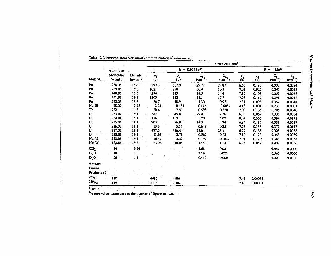
Table12-3.Neutroncrosssectionsofcommonmaterials (continued)
CrossSectionsb
Atomicor E = 0,0253eV E=l MeV
Molecular DensityMaterial Weight (g/cm3) ;) $) (c:~’ ) (cl%-l) $) $) (c%) (c% )
Pu 238.05 19.6 599.3 562.0Pu 239.05 19.6 1021 270Pu 240.05 19.6 294 293Pu 241.06 19.6 1390 362Pu 242.06 19.6 26.7 18.9Nat Si 28.09 2.42 2.24 0.161Th 232 11.3 20.4 7.50u 233.04 19.1 587 45.8u 234.04 19.1 116 103u 235.04 19.1 703 96.9u 236.05 19.1 13.3 5.16u 237.05 19.1 487.5 476.4u 238.05 19.1 11.63 2.71Nat U 238.03 19.1 16.49 3.39Nat W 183.85 19.3 23.08 18.05
t2H2 14 0.94H20 18 1.0D20 20 1.1
AverageFissionProductsof
29.7250.414.568.1
1.300.1160.598
29.05.70
34.30.648
23.60.5620.7971.459
2.682.180.410
27.8713.314.417.70.9220.00840.2202.265.074.740.251
23.10.1310.16371.141
0.0270.0220.000
6.667.017.157.987.314.437.006.788.026.847.736.727.107.016.95
0.1900.0260.1080.1170.0980.0010.1350.0690.3630.1170.3630.1350.1230.1200.057
7.43 0.00036
0,3300.3460.3520.3910.3570.2300.2050.3350.3940.3350.3770.3260.3430.3430.439
0.4490.5600.420
0.00940.00130.00530.00570.00480.00010.00400.00340.01780.00570.01770.00660.00590.00580.0036
0.00000.00000.0000
235U 117 4496 4486239ti 119 2087 2086 7.48 0.00093
aRef 2.bA zero value meanszeroto the numberof figuresshown.

370 P. Rinard
qg~~
POLYETHYLENEALUMINUM
h / I
\
< Al
LEAD
Fig.12.8 Neutronswith I MeVof kinetic energyareshownenteringcylindersof materialfrom the bottom andthenbeingscattering orabsorbed. Thepaths werecalculated usinga Monte Carlo technique.
For example, in the assay of plutonium, moderation is not a desirable effect in thesample region. High-speed neutrons are more able to penetrate the sample and they havelower fission cross sections so that multiplication is less than with low-speed neutrons.On the other hand, in the deteetor region, moderation increases the deteetion efficiencyfor detectors such as 3He proportional counters. By placing hydrogenous material (suchas polyethylene) around the deteetorsj the neutrons cm be counted with more efficiency.Also needed is a falter that will let high-speed neutrons enter the detector region wherethey ean beeome moderated but will not let the moderated neutrons return to the sampleregion where they could produce additional fissions. A layer of material with a largeabsorption cross seetion for slow neutrons (such as cadmium, Figure 12.5) placedbetween the sample region and the detector region is effketive in this regard.
A standard basis for comparing moderating abilities of difierent materials is themoderating power. If one material has a larger moderating power than another, less ofthat material is needed to achieve the same degree of moderation. Two factors *important (1) the probability of a scattering interaction and (2) the average change ‘inkinetic energy of the neutron after such an interaction. To bean effective moderator,both the probability of an interaction and the avetige energy loss in one scatter should behigh. The moderating power is defined as& where ,Z~is the macroscopic scatteringcross section and ~ is the average logarithmic energy decrement in a scatter. Thisdeerement is ln(E&fiJ – In(E&). When elastic collisions in an element with atomicweight A dominate the seattenng process, the deerement becomes

NeutronInteractions with Mauer 371
(A–1)2 ~n (A+l )g= l-—
2A (A-1) “(12-9)
For A > 2, ~ can be approximated by 2/(A+O.67) (Ref. 3). The moderating power ofacompound is given by
Q, = -# (nlcl{l + n2a2&~ + ...) , (12-IO)
where p is the density of the compound, M is its molecular weight, Na is Avogadro’snumber, ni is the number of atoms of element i in one molecule, ~i is the microscopicscattering cross section for element i, and ~i is the logarithmic energy decrement forelement i.
A material with a large moderating power might nevertheless be useless as a practicalmoderator if it has a large absorption cross section. Such a moderator would effectivelyreduqe the speeds of those neutrons that are not absorbed, but the fraction of neutronsthat survive may be too small to be used in a practical manner. A more comprehensivemeasure of moderating materials is the moderating, ratio, ~Zs/Za. A large moderatingratio is desirable; it implies not only a good moderator but also a poor, absorber. For acompound, the moderating ratio is given by Equation 12-10 with each ~i replaced byCS$Cafor element i.
Table 12-4 gives the moderating powers and ratios for some common moderatormaterials for neutrons in the l-eVto 100-keVenergy range (Ref. 4). Ordinary water has ahigher moderating power than heavy water because the atomic weight of hydrogen ishalf that of deuterium. But the hydrogen nucleus (a proton) can absorb a neutron andcreate deuterium much more readily than a deuterium nucleus can absorb a neutron andcreate tritium. This difference in absorption cross sections gives heavy water a muchmore favorable moderating ratio. However, because of its availability and low cost,ordinary water is oflen preferred. The solid niaterials given in the table have a highermoderating ratio than ordinary water and can have fabrication advantages. Polyethyleneis commonly selected as a moderator because of its high moderating power andmoderating ratio.
Table 12-4. Moderating powers and ratios of selectedmaterials (Ref. 4)
Moderating ModeratingPower Ratio
Moderator (1 eV to 100keV) (Approximate)
Water 1.28 58Heavy Water 0.18 21000Helium at STP 0.00001 45Beryllium 0.16 130Graphite 0.064 200Polyethylene (CH.J 3.26 122

372 P. Rinard
12.5 EFFECTS OF MULTIPLICATION IN BULK MATTER
When a neutron interaction yields more than one neutron as a product, a multipli-cation event has occurred. More neutrons will be present in the material after theinteraction than before. The most widely known multiplication event is fission, butother absorption interactions, such as (n,2n), can be important contributors to multipli-cation.
Of the neutrons in a given material at a given moment, some will eventually escapeand the others will be absorbed. Additional neutrons can originate in the material asproducts of the absorption. The definition of the multiplication M is the total numberof neutrons that exist in the sample divided by the number of neutrons that were started.If 1~ neutrons are started in the sample and an additional 59 are found to be createdfrom multiplication events, the multiplication is 1.59. Only a fraction of the firstgeneration of 100neutrons produces additional neutrons through multiplication event$the others escape or are absorbed by other types of interactions. The same fraction of thesecond generation produce a Jhird generation, and so on. The number of neutronsremaining in the sample steadily decreases until it is zero and the total number ofneutrons produced by all the ~ultiplication events is 59.
A related concept that is mdre commonly used is,the multiplication factor. It relatesthe numbers of neutrons in su~essive generiitions. There are two categories of multipli-cation factors that apply to different physical sizes of the material involved.
If the material is infinite in extent, the multiplication factor is written km and isdefinkd as the ratio of the number of neutrons in one generation to the number in theprevious generation. Because iof the infinite size of the material, all neutrons of ageneration become absorbed., Thus km is also the fatio of the number of neutronsprodu~ed in one generation to the number absorbed ih the preceding generation.
If the material M not infinite @ size, some neutrons in a generation may escapethrough the surface and not be absorbe~ th&e are ‘leakage” neutrons. The multipli-catio~ factor for this more practical sit~tion is called ~ff It is defined as the ratio of thenurn~r of neutrons produced ‘inone generation to tilenurnber either absorbed or leakedin the ‘precedinggeneration. The multiplication factor ~ is the more practical ratio forsafquards work because instrumefits are often ‘made small to comply with size andweight constraints.
As an example of ~mand its connection with the multiplication M, consider the casedescribed earlier. The original 100 neutrons would constitute the first generation. If theoriginal neutrons create 37 neutrons through reactions, the 37 neutrons would be thenext generation. The multiplication factor in this case is thus 0.37. With ~ less thanone, the number of neutrons in succeeding generations decreases, eventually reachingzero. As Table 12-5 indicates, it takes 7 generations to reduce the number of neutronsfrom 100 to about zero.
The number of neutrons in one generation is found by multiplying the number in theprevious generation by the multiplication factor ~, which in this example is 0.37. Thisis a statistical process, of course, and the exact number in any generation cannot beexactly,known, but for large numbers of neutrons the ratio of populations in successivegenerations is very nearly constant.
— ——.——— . —.

Neutron Interactions with Matter 373
Table 12-5.Example of neutron popula-tion decline
Average No. ofGeneration Neutrons for kefl = 0.37
1 1002 373 144 55 26 17 0
F9
The multiplication M is readily connected to the multiplication factor ~ff when keffisless than one. By adding together all the numbers of neutrons in all the generations, thegeometric sum can be found
M = 1/(1–~=), ~ff < 1 . (12-11)
With the multiplication of 1.59 in Table 12-5, the multiplication factor is 0.37, showingthat the number of neutrons is decreasing in successive generations.
As ~approaches one, the value of M becomes huger and larger, as shown in Figure12.9.When ~ff = 1, the formula shows that there is no limit to the number of neutronsthat will be produced; in practice, there is a finite number of nuclei that can produce
than one, the sample is supercritica~
10 1 I I I I I I I
9 H
neutrons, so the number of neutrons created is finite but extremely large. Criti&dity issaid to be reached when ~ = 1. If ~R is largerwith ~ less than one, the sample is subcritical.
28 -
~7 –i=6–
sia.5 -~24 -
3–
2–Fig.12.9 Themuitiplication Misshown as ajiunctionof , I
the multiplicationfactor ke Only subcritical 0 0.1 0.2 0.3 0.4 0.5 0.6 0.7 0.8 0.91,0values(k@ less than one)are includedhere. MULTIPLICATION FACTOR K

374 P. Rinard
12.6NEUTRON SHIELDING
To protect personnel from the biological effkctsof neutrons and to reduce backgroundcounts, neutron shielding is ofien necessary. The selection and arrangement of shieldingmaterials vary with the circumstanms. Some general principles can be derived from theneutron interactions with matter described earlier in this chapter.
Thermal neutrons with energies of 0.025 eV or less are absorbed with great effective-ness by thin layers of boron or cadmium, as suggested by the large cross sections shownin Figures 12.4 and 12.5. Boron is ofien used in the form of boron carbide (B4C) orboron-loaded solutions. One commonly used material is Boral, a mixture of boroncarbide and aluminum, which is available in sheets of varying thickness. Cadmium hasthe disadvantage of emitting high-energy gamma rays after neutron capture, which maynecessitate additional gamma-ray shielding. A comparison of Figures 12.4 and 12.5shows that cadmium is more effective than boron for absorbing thermal neutrons,whereas boron is more effective for absorbing epithermal neutrons (energy range 0.1 eVto 10eV).
High-speed neutrons are more difficult to shield against because absorption crosssections are much lower at higher energies. Thus it is first necessary to moderate high-speed neutrons through elastic or inelastic scattering interactions. Inelastic scattering orabsorption may again produce potentially hazardous gamma rays for example, neutroncapture in hydrogen releases a 2.224-MeV gamma ray. An effective radiation shieldconsists of a combination of materials hydrogenous or other low-A materials tomoderate neutron% theimal neutron absorbe~, and high-Z materials to absorb gammarays. Examples of hjbrid shielding materials are polyethylene and lead, concretecontaining scrap iron, and more exotic materials such as lithium hydride. :
In safeguards work viith small, samples of fissionable materials or weak neutronsources, shielding maybe restricted to several centimeters of polyethylene. The shieldingproperties of polyethylene are illustrated in Figure 12.10, which gives dose rates on thesurface of a sphere’of polyethylene with a zszcf sourm in its center. The source emitsneutrons with a high-energy fission spectrum comparable to most uranium and pluto-nium isotopes. Also produced are fission gamma rays and additional 2.224-MeV gammarays from neutron capture in polyethylene. Neutrons provide most of the dose forspheres less than 22 cm in radius beyond that, source gamma rays are the majorcontributors, followed by gamma rays from capture reactions. By increasing the radiusfrom 5 to 12cm or from 20 to 37 cm, the total dose rate can be reduced by a factor of 10.A mle of thumb for neutron dose reduction is that 10cm of polyethylene will reduce theneutron dose rate by roughly a factor ‘of10.
More effkctive shields can sometimes be obtained by adding boron, lithium, or lead topolyethylene. The addition of boron’or lithium results in a lower capture gamma-raydose than that provided by pure polyethylene lead effectively attenuates the source andthe capture gamma-ray flux beca~se it is a heavy element. However, because neutronsprovide most of the dose up to a ridius of 22 cm, the addition of these materials has littleeffkct until the ,shield beqomes subktdntially thickerthan 22 cm. Figure 12,11 shows theeffects on the total dose of adding other materials to polyethylene, these effects areimportant only for shields thicker than 30 cm. Since boron- lithium-, or lead-loaded

NeutronInteractions with Matter 375
3
Kf , .,
Id,
Id’ , .,,
L~?
❑ = TOt~lo = Neutrona = Tdd GMIIma
I , , , , , I5 10 153035303540 45
Radius of Sphere (cm)
Fig.12.10 Variousdoseratb onasphericalsurfacefirornapoint 252Cfsourceinpolyethylene. (Datasupplied by G. E. Bosler,Los Alamos.)
polyethylene is substantially more expensive than pure polyethylene, the additional costis an important consideration.
12.7 TRANSPORT CALCULATIONAL TECHNIQUES
Neutron histories are difficult to determine because of the large number of differentinteractions possible in materials. This difficulty is fiwther increased when the compo-sition of matter changes frequt$tly along the path of a neutron, as it otlen doesthroughout the volume of an assayinstmment. Techniques for calculating the behavioror transport of neutrons and ~ma rays in such circumstances are important for thedesign of assay instrument the interpretation of measurements, and the developmentof shielding configurations. Two ~echniques for calculating the transport of neutrons inmatter are described briefly in Se@ions 12.7.1 and 12.7.2.
12.7.1 Monte Carlo Techniques
The tmbability of a neutron interaction occurring is an important feature in thedescription of neutrons traveling through matter. Instead of trying to predkt what anindividual neutron may do, one can use procedures to predict what fractioti of a largenumber of neutrons will behave ~in some manner of interest. Calculational techniquesthat, in simplistic terms, predict neutron events with “rolls of dice” (actually thegeneration of random numbers in a computer) are called Monte Carlo methods. The

376 P. Rinard
3
.::,
L
.G
J 10”,.. :::,;.:aJ
&8 10-’:— LEGEND
❑ = pure Poly
G 0. kron – POIY :!::: :A = Lithium - poly ::::: :
+ = Lead – Poly
, r I , , ,5 10 15202530 s540 45
Radius of Sphere (cm)
Fig.12.11 Total dose rateon a sphericaisurjacefrom a point 252Cfsourceinvariousmaterials. (Data supplied by G.E. BosIer,Los A!amos.)
response of an assay system can ofin be calculated from the transport of manyindividual neutrons, despite the inclusion of a few improbable neutron histories thatdeviate drastically ihm the average behavior.
The Monte Carlo method can allow a detailed three-dmensional geometrical modelto be constructed mathematically to simulate a physical situation. A neutron can bestarted at a selected location with a certain energy and direction. It travels distances thatare consistent with the mean-fkee-pa$hlengths in the materials, with random variationstim the expected mean. At the end of each step in the neutron’s path, a decision maybemade to simulate a certain interaction, with the decision based on the cross section forthe interaction with that material at that neutron energy. If an interaction is selected, theresults of the interaction are simulated and its consequences followed. Eventually, apoint is reached where no further interest in the neutron exists and its history isterminated. This might occur with the escape of the neutron or its moderation to verylow energy. The neutron might be absorbed followed by the emission of a gamma ray ofno interes$ or it might undergo a multiplication event. If a multiplication event occumthe histories of the new neutrons are followed. In principle, the history of a simulatedneutron is one that might actually occur with a real neutron.
By repeating this procedure for many thousands of neutrons and by keeping tallies ofhow many entera detector region, how many cause fissions how many escape through ashieldj or whatever else is of interest, an average behavior and its uncertainty aregradually deduced. Many specialized techniques may be used to get good average valueswith the fewest number of neutrons, but there are cases where even a fist computercannot provide enough histories within the constraints of time and budget. Nonetheless,

Neutron Interactions with Matter 377
Monte Carlo techniques provide essential assistance in design work by closely modelingthe actual geometry of a problem and by having imaginary neutrons that simulate themotions and interactions of real ones. Examples of the results of Monte Carlo calcula-tions are the shielding calculations in Figures 12.10 and 12.11 and the coincidencecounter design calculations described in Chapters 14and 17.
12.7.2 Discrete Ordinates Techniques
Analytical transport equations exist that describe the exact behavior of neutrons inmatter. However, only approximate numerical solutions to these equations can beobtained for complicated systems. Procedures for obtaining these numeral solutions areclassified as discrete ordhates techniques.
Some important differences distinguish discrete ordinates techniques from MonteCarlo techniques. Only one- or two-dimensional geometries are generally practical witha dkcrete ordinates process, and the neutrons are considered to be at discrete locationsinstead of moving fkeelythrough a threedimensional geometry. In a twodimensicmaldiscrete ordinates case, for example, it is as if the surface material were covered by a wiremesh and the neutrons existed only at the intersections of the wires. Furthermore, theenergy of a neutron at any time must be selected from a finite set, in contrast to thecontinuously varying energy of a neutron in the Monte Carlo method.
Despite these disadvantages, discrete ordinates techniques can produce useful resultsin many cases. For problems involving large volumes and amounts of materials (such asreactor cores), the Monte Carlo technique can be too cumbersome and slow, a discreteordinates solution might be feasible.
1.
2.
3.
4.
D. L Garber and R. R. Kinsey, “Neutron Cross Sections, Vol. II, Curves,”Brookhaven National Laboratory report BNL 325 (1976).
Evaluated Nuclear Data File ENDF/B-V (available tlom and maintained by theNational Nuclear Data Center of Brookhaven National Laboratory).
J. R. Lamarsh, Introduction to Nuclear Reactor Theory (Addison-Wesley, Reading,Massachusetts, 1966).
S. Glasstone and A. Sesonske, Nuclear Reactor Engineering (D. Van Nostrand Co.,Inc., Princeton, New Jersey, 1967).

.