Embed Size (px)
Citation preview

The Official Electronic Publication of The Association of Technology, Management, and Applied Engineering • www.atmae.org
© 2010
Neural Network Controlled Energy Saver for Induction Motor Drive
By Ms. Jamuna Venkatesan & Dr. S. Rama Reddy
Volume 26, Number 1 - January 2010 through March 2010
Peer-RefereedApplied Papers
ElectricityElectronics
Energy
KEyworD SEarCh

2
Journal of Industrial Technology • Volume 26, Number 1 • January 2010 through March 2010 • www.atmae.org
Neural Network Controlled Energy Saver for Induction Motor DriveBy Ms. Jamuna Venkatesan & Dr. S. Rama Reddy
AbstractIn this paper, a new model for a neural-network-controlled single phase induc-tion motor is presented. The neural-network-based control scheme has been developed using a pulse width modula-tion technique. It is used to implement the energy-saving scheme of single-phase Induction motors, when they operate under no load or small duty-ratio load. The pulse width modulated AC chopper fed single phase induction motor is implemented using an Atmel 89C51microcontroller. The intention is to save energy in plants using induction motors. At no load, 58% of the energy can be saved that decreases with an increase in the load. The neural net-work is trained to estimate the required voltage at different load conditions. To provide the required data to train the neural network, a simulation program was written to obtain the duty ratio val-ues at different load conditions. From the simulation results, it is seen that the pulse width modulated (PWM) AC chopper system has lesser harmonics than the phase controlled AC chopper system, and hence it is used in the pres-ent work. The neural network based closed-loop control scheme to imple-ment the energy-saving of the single phase induction motor drive system is designed and presented. The possibility of energy saving is explored in loads like punching and drilling industries, where most of the induction motors run at no load.
IntroductionThere is a growing demand for power in the world. The generation is not able to meet the load demand. In addition, losses occur in transmission systems. Therefore, it is better to develop energy savers to conserve the energy that can minimize the load demand. Intelli-
gence-controlled energy savers are not readily available in the market. Micro-controller-based energy savers have been investigated by Xue and Cheng (2006). Microcontroller-based energy savers can be used only for linear load applications, whereas, most of the loads found in industries are non-linear. Thus, developing a neural network controlled energy saver has economic sense. This project can be used in medium and large-scale industries, as it leads to a considerable saving in energy.
In modern cities, motor drive systems can consume over half the electric-ity. Furthermore, those systems can consume over 75% of all the electricity in an industrial plant (Xue and Cheng, 2006). In industrial complexes like drilling mills, most of the induction motors run at no load. These motors are always connected to the mains ir-respective of the load conditions. Due to the rated voltage at stator terminals, rated iron losses have to be supplied constantly to the motors. These losses mean a waste of some form of energy, which is in short supply. If it is possible to reduce the voltage at the stator termi-nals during no load or small duty ratio load conditions, then iron losses can be reduced and some electrical energy might be saved (Hunyar and Veszpremi, 2001). Voltage controllers are increas-ingly applied as motor soft starters and sometimes as energy savers, reducing the flux level in the connected induc-tion motor, in accordance with the load (Kioskeredis and Margaris, 1996).
The use of a practical silicon controlled rectifier voltage controller results in considerable harmonic distortion and substantial additional losses, which reduce the net energy saving. The main problems associated with the silicon
Dr. S. Rama Reddy is professor in the Electrical and Electronics Engineering Department, Jeru-salem College of Engineering, Chennai, India. He obtained his D.E.E from the S.M.V.M. polytech-nic, Tanuku, A.P., A.M.I.E. in Electrical Engineering from the Institution of Engineers (India), M.E. in Power Systems from Anna University, Chennai and Ph.D in the area of Power Electronics from Anna University, Chennai, India. He has published over 40 technical papers in national and interna-tional conferences proceedings / journals. He has secured the A.M.I.E. institution gold medal for ob-taining the highest marks. He has won the AIMO best project award and Vijaya Ratna Award. He has 20 years of teaching experience. His research interests include the areas of resonant converters and FACTS. He is a life member of the Institution of Engineers (India), Indian Society for Technical Education, Systems Society of India, Society of Power Engineers and Institution of Electronics and Telecommunication Engineers (India). He has published text books on Power Electronics, Solid State Circuits and Electronic circuits.
Ms. Jamuna Venkatesan is Assistant Professor in the Electrical and Electronics Engineering Depart-ment, Jerusalem College of Engineering, Chennai, India. She received her B.E. degree in Electrical & Electronics Engineering from St. Peter’s Engineer-ing College, Madras University, Chennai, India in 1999, and the M.E. degree in Power Electronics and Drives from Anna University, Chennai, India in 2005. She has secured the 5th university rank in her M.E. degree. She has published 6 technical papers in national and international conferences proceedings / journals. She has 10 years of teach-ing experience. Her research interests include Induction Motor Drives and Neural Network con-troller for the drives. She is a life member of the Indian Society for Technical Education. She has published a text book on Power Electronics.
3
Journal of Industrial Technology • Volume 26, Number 1 • January 2010 through March 2010 • www.atmae.org
controlled rectifier voltage control-ler are the high harmonic contents in the supply and motor currents, very poor power factor especially at light loads, and low efficiency. The pulse width modulated AC chopper can help in modifying these parameters. With the increased availability of power MOSFETs and insulated gate bipolar transistors, a new generation of simple choppers for AC inductive loads is foreseen. Pulse width modulated AC chopper controllers can replace the AC controllers with thyristor technol-ogy, which can overcome the above drawbacks (Ahmed, Amei and Sakuri, 1999; Meco-Gutierrez, Perez-Hidalgo, Vargas-Merino and Heredia-Larrubia, 2007). The pulse width modulated AC chopper is inferior to the phase angle control scheme for an induction motor (Sundareswaran, Rajasekar and Sreede-vi, 2006; Hongxiang, Min and Yancho, 2004).
Energy conservation is significant for induction motors. Because harmonics generates additional energy consump-tion, how to eliminate harmonics is important for energy conservation in induction motors (LuGuangqiang, Guangfu, Hongxiang and Ynchao, 2004). The performance characteristics of a symmetrical pulse width modu-lated single-phase AC chopper control-ler-fed single-phase induction motor to achieve variable speed operations are evaluated. The controller employs a chopper circuit on the stator side of the motor. Speed control is achieved by varying the duty cycle of the switching function of the chopper as a suitable means for controlling the effective voltage applied to the motor terminals. (Ahmed, Amei and Sakuri, 2000). Asaii, Gosden and Sathiakumar (1996) described the application of neural networks to the sensorless control of the speed of an electric vehicle-induc-tion-machine drive. Mademlis (2005) investigated the problem of efficiency optimization in capacitor-run single-phase induction motors.
The pulse width modulated AC chopper and phase angle controlled AC chopper fed induction motor systems are simu-
lated and their performances are com-pared (Jamuna and Reddy, 2008). It is proved that the pulse width modulated AC chopper system has lesser total har-monic distortion and better power fac-tor. With reduced voltage, energy can be saved during the no load and partial load periods of a single phase induction motor drive (Jamuna and Reddy). The possibilities of applying off-line trained artificial neural networks in creating the system inverse models, that are used in designing the control algorithm for a non-linear dynamic system were described by Zilkova, Timko and Gi-rovsky (2006).
Motor drives are popularly applied in air conditioning, fans, pumps, compres-sors, chillers, escalators, elevators and industrial drives. Common motor drives include induction motor drives, DC mo-tor drives, synchronous motor drives, switched reluctance motor drives, as well as other motor drives. Among these drives, a single phase induction machine is most widely used in indus-try because of its simple construction, reliable operation and lightness. Xue and Cheng (2006) proposed a control scheme for the energy saving of three-phase induction motor drive systems operating under long-term light-loads or small duty ration loads, based on the variable voltage control.
In the reviewed literature, investiga-tions on an AC Chopper fed single
phase induction motor controlled by a neural network have not been pre-sented. In industries, an energy saving scheme has not been implemented using neural networks. In the previ-ous works and papers related to energy conservation, an induction machine is used instead of its mathematical model. Simulink available through Matrix Laboratory (MATLAB) is one of the most commonly used tool for simulat-ing power electronic systems. In the work discussed, the simulink model for induction motor is developed using the double field revolving theory. In the double field revolving theory, two rotating fields replace a rotor. M files needed for the neural network system are developed. To save energy in no load and partial load conditions, a neural-network-based closed loop sta-tor voltage control method is employed. Prototype hardware is implemented us-ing the ATMEL’s AT89C51 embedded microcontroller.
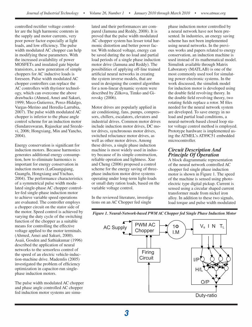
Circuit Description And Principle Of OperationA block diagrammatic representation of the neural network controlled AC chopper fed single phase induction motor is shown in Figure 1. The speed of the machine is sensed using photo-electric type digital pickup. Current is sensed using a circular shaped current transformer made from nickel iron alloy. In addition to these two signals, load torque and pulse width modulated
Figure 1. Neural-Network-based PWM AC Chopper fed Single Phase Induction Motor

4
Journal of Industrial Technology • Volume 26, Number 1 • January 2010 through March 2010 • www.atmae.org
The current through the rotor compo-nent,
(6)
The voltage across the variable resistance, (7)
The torque developed by the motor is given by the expression
(8)
The electromechanical equation is expressed as (9)
where, w = (10)
output voltages are considered to train the neural network. Based on these four parameters, the neural network gener-ates the driving pulses to the switches by considering the load conditions to save energy.
Pulse width modulated output volt-age (V
S), stator current (I), Speed (N)
and load torque (TL) are independent
variables for the neural network. Driv-ing pulses to the switches, i.e. the duty ratio, is a dependent variable. With a conventional controller, training data such as dependent and independent variables are collected. These data are used to train the model. Every time, the weights and biases at the input layer (I/P), hidden layer (H/L) and output layer (O/P) of the neural network are updated using the backpropagation algorithm (Asaii, Gosden and Sathiaku-mar, 1996).
Model Of A Single Phase Induction MotorAccording to the double field revolving theory, any alternating quantity can be resolved into two rotating components that rotate in opposite directions, each having half the maximum magnitude of the alternating quantity. The rotor of a single phase induction motor can be considered as two rotating fields. These fields have the same magnitude and revolve at a synchronous speed in opposite directions. Since the value of slip(s) is generally small, r21/2s is considerably higher than r21/[2*(2-s)]. In general, the magnitude of the output voltage (V0) is 90% to 95% of the applied voltage. Hence, to obtain the simplified model of a single phase induction motor, the effect of the back-ward field is neglected. The generalized SIMULINK model of a single phase induction motor is shown in Figure 2. The nomenclature for the various pa-rameters used for the modeling is listed in Table1.
The current flowing through the stator is expressed as
(1)
If the rotor current referred to the stator is taken as
I 2
1 then the iron-loss and magnetizing component of the no-load current can be expressed as (2)
The core loss component of current is (3)
The output voltage can be obtained from the expression
(4)
The current through the magnetizing component,
(5)
Table 1. Nomenclature for parameters s Slip (no unit)r1 Stator resistance in ohmsr2 Rotor resistance referred to stator in ohmsr0 Equivalent resistance corresponding to the iron losses in ohmsL1 Leakage inductance of stator in henry L2 Leakage inductance of rotor referred to stator in henryL0 Magnetizing inductance of the stator in henryVi Input voltage in voltsV0 Output voltage in voltsV1 Voltage across the variable rotor resistance in voltsI Current flowing through the stator in AmperesI1 Iron-loss and magnetizing component of the no-load current in AmperesI1c Core loss component of current in AmperesI1m Magnetizing component of current in AmperesI2 Rotor current referred to the stator in AmperesT Torque in Nmns Synchronous speed in rpsJ Moment of inertia in Kgm2B Viscous friction in Nms P Poles w Angular speed in rad/secθ Angular displacement in radians
I1 =(V – V0)(r1 + jx1)
I0 = I1 – I 21
I0c = I0 – I0m
V0 = I0c *
I0m =
I 21 =
T = (I 21)2 *
T = J + Bw + TL
r0
2(
(
V0
jx0
2(
(
V1(s) = R2 * I1(s)
(V0 – V1)
(
(jx21
2
2 π n s
(
(r21
2s
dwdt
dθdt

5
Journal of Industrial Technology • Volume 26, Number 1 • January 2010 through March 2010 • www.atmae.org
From the Laplace transformation of equations (1) – (10), the model of a single phase induction motor is ob-tained.
Artificial Neural Networks The neural network system to estimate the duty ratio of an AC chopper fed single phase induction motor is shown in Figure 3. It consists of an input layer, a hidden layer and an output layer, where each layer has a specific func-tion. The input accepts an input data and distributes it to all the neurons in the hidden layer.
The input layer is usually passive and does not alter the input data. The neu-rons in the hidden layer act as feature detectors. They encode in their weights a representation of the features present in the input patterns. The output layer ac-cepts a stimulus pattern from the middle layer and passes the result to a transfer function block, which constructs the output response pattern of the network (Freeman and Skapura, 2002).
The number of hidden layers and the number of neurons in each hidden layer depend on the network design consid-eration and there is no general rule for an optimal number of hidden layers or nodes. The hidden layer transfer function is log-sigmoid or tan-sigmoid and the output transfer function is usually linear. Equations 11 and 12 show the transfer functions, where X is the input vector, Y and O are the output vectors of the hidden layer and output layer respectively. V
ji, W
kj are
the weight matrices, and B1 and B
2 are
the bias vectors (Asaii, Gosden and Sathiakumar, 1996). Equations 11 and 12 show the transfer functions, where X is the input vector, Y and O are the output vectors of the hidden layer and output layer respectively. V
ji, W
kj are
the weight matrices, and B1 and B
2 are
the bias vectors (Asaii, Gosden and Sathiakumar, 1996).
(11)
(12)
The algorithm of the backpropagation of the error is the most well-known algorithm for the training of the multi-layer networks. The flowchart for the error backpropagation algorithm is given in Figure 4.
Closed Loop Stator Voltage Controlled Single Phase Induction MotorVoltage supplied to the induction motor is varied according to the load conditions. The energy saving in these four cases is tested under four condi-tions - no load with rated voltage, no load with reduced voltage, partial load
with rated voltage and partial load with reduced voltage. Energy can be saved at no load and partial load conditions with reduced voltage operations. In a no load condition, the supply voltage of the induction motor is changed in steps from 20% to 100% of the rated voltage using the pulse width modulation tech-nique. At no load, for various voltage values, the copper loss and iron loss are measured and the net electrical losses are calculated. During each step, the saving in energy is calculated by using the equation (13).
Figure 2. Simulink model of single phase induction motor
Figure 3. Nural Network system to estimate duty ratio of PWM AC Chopper fed Single Phase Induction Motor
V I1 I0 I0c V0
1sL2
1/2
1sL0/2
1Js+B
1r1+sL1
V1 and T Calculation
r0/2
TL
V0 I 2
1 I0m
V1
V0 I 2
1
I21
ω
V1
T
+ + +
+
+
PWM voltage
Stator current
Speed
Error in speed
Duty ratio
Input layer Hidden layer
Output layer
Y =
O = Wkj.Y + B2
1(1 + e –(vji.X+B1))

6
Journal of Industrial Technology • Volume 26, Number 1 • January 2010 through March 2010 • www.atmae.org
(13)
In a no load condition, the loss at full voltage (230V) is 400 watts and 20% of the voltage (46V) results in a loss of 168 watts. Hence, 20% of the rated voltage results in an energy saving of (400-168)/400 =58%. The power factor is improved from 0.31 to 0.81 with a slight reduction in speed. Similarly the % of energy saved can be calculated for 30%, 40%…. of the rated voltage. The results are shown in Figure 5.
In partial load conditions, the drive sys-tem is operated with various duty-ratio values. From the studies, it is seen that from no load to 20% of the rated load, the saving in energy is modest. For the same model, simulation was carried out for 20% of the rated load. The loss at full voltage (230V) is 470watts and 70% of the voltage (161V) results in a loss of 362watts. Hence, one can see that, 23% of the energy can be saved, when the machine is operated at 70% of the rated voltage.
From the above results, it is found that energy can be saved during no load and partial load operations. In order to achieve closed loop control using the neural network, the load torque is sensed continuously. Based on the load torque values, the trained neural network adjusts the voltage applied to the stator of an induction motor. The neural-network-based energy saving scheme for a single phase induction motor drive system used for simulation is shown in Figure 6. The SIMULINK model for the power circuit used to generate the pulse width modulated AC voltage is developed, and the same is used for simulation. The pulse width modulated AC voltage is applied to the single phase induction motor. A 1horse power, 230V Single phase induction motor with the parameters shown in Table 2 is used for simulation. Figure 6 shows the results obtained by replacing the variables used in the Figure 2 with these parameters.
To provide the required data to train the neural network, a simulation program was written to obtain the duty ratio values for different load torques. Using this program, 1 million sets of the train-ing pattern such as pulse width modu-lated output voltage, stator current, speed of the machine, load torque and duty ratio values are obtained. These patterns are used for training the neural network using the error backpropa-gation algorithm. Using the training pattern, the neural network was trained successfully and a neural network controller replaced the matlab program.
Figure 4. Flowchart for Error backpropagation algorithm
Figure 5. Performance characteristics of PWM AC Chopper fed Induction Motor at various voltage steps during no-load operation
Stop
More patterns in the training set
E < Emax
No
Yes
Adjust weights of hidden layer
Adjust weights of output layer E ← 0
Calculate error signal vector of output layer and error signal vector of hidden layer
Compute cycle error
Submit pattern and compute output layer and hidden layer responses
Initialize weights of output layer, hidden layer, error (E) and maximum error (Emax)
Begin of new training step
Yes
No
Begin of new training cycle
Speed vs Modulaation Index
0200400600800
1000120014001600
0.2 0.4 0.6 0.8 1
Modulaation Index
Spee
d in
rpm
% Energy saving vs Modulation Index
0
10
20
30
40
50
60
70
0.2 0.4 0.6 0.8 1
Modulation Index
% E
nerg
y sa
ving
Power factor vs Modulation Index
00.10.20.30.40.50.60.70.80.9
0.2 0.4 0.6 0.8 1
Modulation Index
Pow
er fa
ctor
% slip vs Modulation Index
0
5
10
15
20
25
30
0.2 0.4 0.6 0.8 1
Modulation Index
% s
lip
% Save = (Losses at full voltage – Losses at reduced voltage)
Losses at full voltage

7
Journal of Industrial Technology • Volume 26, Number 1 • January 2010 through March 2010 • www.atmae.org
Table 2.Parameters of single phase induction motor
Parameter Values
r1
2Ω
x1
5.12Ω
r2
1.01Ω
x2
0.26Ω
r0
300Ω
x0
47.12Ω
J 0. 0146Kgm2
B 0.007Nms
Turns ratio 1.99
Poles 4
Table 3. Matlab function to calculate voltage and torque
function y =vandt(in)I21 =in(1);w =in(2);s =(157-w)/157;r2 =1.01/s;y(1) = I21*r2;y(2) = I21* I21*r2/157;end
Table 4. Matlab function for PWM generation
function out =pwm(a)vs = a(1);t = a(2);k = a(3);T =.0008;t1 = mod(t,T); if t1 <=k*T
out(1)=vs;else out(1)=0;end
Table 5. Matlab function for non-linear load
function out =loadtorque(a)t = a(1); If t <2
out(1)=14; else if t <7
out(1)=3;else out(1)=0; end
The output of the neural network con-troller is used to vary the duty ratio of the pulse width modulated AC chopper. Various calculations in Figure 6 are done using the Matlab functions given in Tables 3,4, and 5.
Based on the load torque applied to the machine, the neural network controller controls the duty-ratio. Hence, energy can be saved in no load and partial load conditions. For example, the model shown in Figure 6 is operated in a full load condition for a certain period. The load is reduced and it is operated with 20% of the rated load for some time and then it is further reduced to no load for the remaining period as shown in Figure 7.
The neural network estimates the duty-ratio values in different load conditions so that the energy is saved in no load and partial load conditions as shown in Figure 8. In various load conditions, the copper loss and iron loss are measured and the net electrical losses are shown in Figure 9. From this figure it is seen that, by varying the duty-ratio, the losses during no load and partial load periods are lesser. Hence, energy can be saved in partial load and no load conditions.
Experimental VerificationFor experimental verification, a 1 horsepower, 230V induction motor was used. The hardware was implemented using the AT89C51 microcontroller. It consists of a small capacitor of 11µf, as a voltage suppressor, placed across the freewheeling path in order to avoid problems of high-voltage transients that can occur if both the switches are switched off in the presence of a reac-tive load. The experimental set up of the hardware implemented is shown in Figure 10.
The hardware circuit of the pulse width modulated AC chopper fed drive is shown in Figure 11. The main part of the control circuit is the microcon-troller. The line-interfacing unit gives the information about the AC supply to the microcontroller. An assembly language program is written in the microcontroller to generate the driving
Zero-Order
Hold1
Zero-OrderHold
1
.000815s
1
.0146s+.007
1
.15s
1
.0163s+2
Torque
Modulationindex
neuraldata
losses
Speed
Sine Wave1
p1y 1
Neural Network1
u2
u2
u2
MATLABFunction
MATLABFunction
MATLABFunction
300
4
2
300
Clock
Figure 6. Model of the Neural Network controlled Pulse Width Modulated AC Chopper fed Single Phase Induction Motor
pulses. Thus, the gating pulses required by the switches are obtained from the microcontroller. The flow chart to obtain the driving pulses for the three switches is given in Figure 12.
For various load conditions, the value of duty-ratio can be changed to adjust the input voltage for energy saving. By trial and error, the optimal values of du-ty-ratio are found using the simulation.

8
Journal of Industrial Technology • Volume 26, Number 1 • January 2010 through March 2010 • www.atmae.org
The same values of duty-ratio are used for the experimental verification. For 1 horsepower induction motor, at no load condition, duty ratio is set to 0.2 using AT89C51 and the readings are noted. For 20% of the rated load, the duty-ratio is changed to 0.7 and the readings are noted. Similarly for various load conditions, the duty ratio values can be changed to adjust the input voltage to yield the energy saving.
From the experimental set up, the read-ings are noted and tabulated as shown in Table 6. The saving in energy in a no load condition is calculated for various duty-ratio values using equation (13).
Gating pulses and the output voltage are captured using the oscilloscope and they are shown in Figure 13.
It is found that 62% of the energy can be saved in a no load condition with reduced voltage.
ConclusionA new SIMULINK model for the pulse width modulated AC chopper fed single phase Induction motor system was developed. A neural network is trained successfully using the error backpropa-gation algorithm and it is used to vary the duty ratio value depending upon the load conditions. Systematic inves-tigations on an induction motor model with respect to energy saving led to the following results and conclusions: In a no-load operation with 20% of the rated voltage applied to the stator, the energy saving is as high as 58% and the power factor improves from 0.31 to 0.81. From no load to 20% of the rated load, the saving in energy is modest. At 20% of the rated load, 23% of energy can be saved with 70% of the rated voltage applied to the stator.
In industrial units like a punching press and drilling machinery, most of the induction motors often run at no load or partial load. The rated efficiency of an induction motor is high when it runs under the full load. Therefore, even a modest improvement in the energy ef-ficiency of induction motor drives can imply huge energy-saving. Using the
0 1 2 3 4 5 6 7 8 9 100
2
4
6
8
10
12
14Load torque vs time
Load
tor
que
in N
m
Time in msec 0 1 2 3 4 6 8 9 10
0
0.2
0.4
0.6
0.8
1
Modulationindex vs Time
Mod
ulat
ioni
ndex
Time in msec
0
100
200
300
400
500
600
700
1 2 3 4 5 6 7 8 9 10
Tim e in m se c
Loss
es in
wat
ts
Figure 7. Variation in load torque
Figure 9. Loss in various load conditions
Figure 10. Experimental setup
Figure 8. Variation in Modulation Index estimated
Table 6. Experimental values in a no load and partial load condition
Load condition Voltage in Volts
Current in Amps
Power in Watts
Energy saving in %
Noload
230 4.1 228 -47 1.2 87 62%
Partial load
230 5.2 440 -161 2.3 330 25%

9
Journal of Industrial Technology • Volume 26, Number 1 • January 2010 through March 2010 • www.atmae.org
10K
6
A
T 8 9 C 2 0 5 1
10K
10µF
10
µF
+5V
1 4 5 10
20
11M
Hz
33μF
33μF
12
2
~
7812
1
3 2
2mF
1K
+12V
230/
15V
7805
1
3 2 2m
F
+5V
G
230V
50
Hz
I R 2 1 1 0
1 5 6 9
2 3 7
10
12
13
22K
22K
O/P
O/P
47μF
1μF
+5V 47
μF
100Ω
100Ω
Not
ga
te
~
7805
7905
2 1
3 3
2 1
1000
pF
1000
pF
~
1K
1K
7
2
3
4
+5V
-5V
+ - IC74
1
VS
LED
230/
6-0-
6V
230V
50
Hz
1
IM
~
S M
S F
START
PORTINITIALISATION
WAIT
A
a. Main Routine
A
START
IS INTERRUPT OCCURED?
NO
YES
INITIALISE TIMER
TURN ON MAIN SWITCH
CLEAR TIMER
INITIALISE TIMER
TURN ON FREE WHEELING SWITCH
CLEAR TIMER
STOP
b. Sub Routine
A
Figure 12. Flow Chart for the generation of Control Pulses
Figure 11. Modulated AC chopper fed drive
Figure 13. Experimental Results
50µs/div 5v/div
50µs/div 5v/div
b. Output voltage of AC chopper
a. Driving Pulses for 50% and 20% duty-ratio
50ms/div 50v/div
50µs/div 5v/div

10
Journal of Industrial Technology • Volume 26, Number 1 • January 2010 through March 2010 • www.atmae.org
proposed scheme, the voltage at the sta-tor terminals is reduced during no load or small duty ratio load conditions, and electrical energy is saved. The experi-mental results are almost similar to the simulation results.
ReferencesAhmed, N.A., Amei, K., & Sakuri,
M. (1999). A new configuration of single-phase symmetrical PWM ac chopper voltage controller - IEEE Transactions on Industrial Electron-ics, vol.46, No.5, pp 942-952.
Ahmed, N.A., Amei, K., & Sakuri, M. (2000). AC Chopper voltage controller-fed single phase induc-tion motor employing symmetrical PWM control technique – Electric Power Systems Research 55 (2000), Elsevier, pp-15-25.
Asaii, B., Gosden, D.F., & Sathiakumar, S. (1996). Neural Network Applica-tions in Control of Electric Vehicle Induction Machine Drives - IEE Transactions on Power Electronics and Variable Speed Drives, Confer-ence publication No.429, pp273-278.
Freeman, J.A., & Skapura, D.M. (2002). Neural Networks Algorithms, Appli-cations, and Programming Tech-niques, Pearson’s Education, Asia, Ed. 6.
Hongxiang, Y., Min, L., & Yancho, J. (2004). An advanced harmonic elimination PWM technique for AC choppers – 35th Annual IEEE Power Electronics specialist’s conference, pp161-165.
Hunyar, M., & Veszpremi, K. (2001). Pulse width modulated IGBT ac chopper - Periodical polytechnic SER.EL.ENG, vol. 45, pp 159-178.
Jamuna, V., & Reddy, S.R. (2008). Neural Network controlled Energy Saver for Induction Motor Drives - International conference on Power Electronic Drives and Power systems POWER COIN, pp 36 – 37.
Kioskeredis, I., & Margaris, N. (1996). Loss minimization in scalar con-trolled induction motor drives with search controllers –IEEE Trans. On Power Elec., Vol. 11, No.2, pp. 213-220.
LiGuangqiang, Guangfu, L., Hongxi-ang, Y., & Ynchao, J. (2004). Energy Conservation of A Novel Soft Starter Controlled by IGBT for Induction Motors with Minimum Current - Proceedings of IEEE international symposium on industrial electronics, Vol.2, pp 1351 – 1356.
Mademlis, C. (2005). Optimization of Single-Phase Induction Motors- Part I: Maximum Energy Efficiency Con-trol - IEEE Transactions on Energy Conversion Vol. No 20, pp187-195.
Meco-Gutierrez, M.J., Perez-Hidalgo, F., Vargas-Merino, F., & Heredia-Larrubia, J.R. (2007). Pulse Width Modulation technique with harmonic injection and frequency modulated carrier: formulation and application to an induction motor - IET Electr. Power Appl., 1(5), pp 714-726.
Sundareswaran, K., Rajasekar, N., & Sreedevi, V.T. (2006). Performance comparison of Capacitor-Run induction motors supplied from AC voltage regulator and SPWM AC Chopper – IEEE Transaction on Industrial Electronics, Vol.53, No.3, pp990-993.
Xue, X.D., & Cheng, K.W.E. (2006). An Energy-Saving Scheme of Variable Voltage Control for Three-Phase Induction Motor Drive Systems -2nd International Conference of power Electronics Systems and Applica-tions, pp241-243.
Zilkova, J., Timko, J., & Girovsky, P. (2006). Nonlinear system control using neural networks - Acta Poly-technica Hungarica, Vol.3, No.4, pp 85-94.