Embed Size (px)
Citation preview
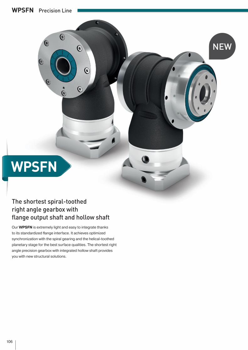
WPSFN
WPSFN Precision Line
NEW
The shortest spiral-toothed right angle gearbox with flange output shaft and hollow shaftOur WPSFN is extremely light and easy to integrate thanks to its standardized fl ange interface. It achieves optimized synchronization with the spiral gearing and the helical-toothed planetary stage for the best surface qualities. The shortest right angle precision gearbox with integrated hollow shaft provides you with new structural solutions.
106

1
2
3
WPS
FN
1
2
3
WPSFN Precision Line
Minimized backlash for maximum precision (< 3 arcmin)
For any mounting position
Individual adaptation of the input fl ange to the motor
Lifetime lubrication for maintenance-free operation
Counterdirectional rotation
Clamping systems with optimized mass moment of inertia
Greater quality due to high-class gearing
Thanks to its spiral gearing, the WPSFN achieves optimal, homogeneous synchro-nism. The two-stage right angle precision gearbox operates with extremely low vibration with the helical-toothed planetary stage. As a result, your machine produces the highest surface quality and the best prints.
Standard flange interface with hollow shaft
The WPSFN right angle precision gearbox with its EN ISO 9409-1 standard fl ange interface allows you to quickly integrate drive components such as a fl anged pinion or turntable. Discover new design solutions for fl exible line routing with the hollow shaft integrated in the single-stage WPSFN.
Space-saving thanks to minimal installation height
The WPSFN is the shortest right angle precision gearbox. Depending on the frame size, you may use up to 25% less installation space than with comparable right angle gearboxes with spiral gearing.
107

WPS
FNWPSFN Technical data
(1) Number of stages(2) The ratio-dependent values can be retrieved in Tec Data Finder – www.neugart.com(3) Sound pressure level from 1 m, measured on input running at n1=3000 rpm no load; i=5(4) Max. motor weight* in kg = 0.2 x Mb / motor length in m
* with symmetrically distributed motor weight * with horizontal and stationary mounting
(5) These values are based on an output shaft speed of n2=100 rpm(6) Based on the end of the output shaft(7) Other (sometimes higher) values following changes to T2N, Fr, Fa, cycle, and service life
of bearing. Application specific configuration with NCP – www.neugart.com
Code Gearbox characteristics WPSFN064 WPSFN090 WPSFN110 WPSFN140 z(1)
Service lifetL h
20,000Service life at T2N x 0.88 30,000
Efficiency at full load(2) η %94 193 2
Min. operating temperature Tmin °C (°F)
-25 (-13)Max. operating temperature Tmax 90 (194)Protection class IP65
S Standard lubrication OilF Food grade lubrication Oil
Installation position AnyS Standard backlash
jt arcmin< 5
R Reduced backlash < 3 2
Torsional stiffness(2) cg
Nm/arcmin (lbf.in/
arcmin)
1.9 - 2.6 (17 - 23)
4.0 - 5.5 (35 - 49)
10.1 - 13.5 (89 - 119)
26.0 - 34.5 (230 - 305) 1
5.3 - 6.9 (47 - 61)
15.3 - 20.5 (135 - 181)
33.5 - 44.0 (296 - 389)
85.0 - 111.0 (752 - 982) 2
Gearbox weight mGkg
(lbm)3.3 (7.3) 6.1 (13.5) 10.9 (24.0) 24 (52.9) 13.7 (8.2) 5.3 (11.7) 8.4 (18.5) 17.8 (39.2) 2
S Standard surface Right angle housing: Aluminum – anodized (black)Running noise(3) Qg dB(A) 66 67 68 70
Max. bending moment based on the gearbox input flange(4) Mb
Nm (lbf.in)
12 (106) 25.5 (226) 53 (469) 120 (1062) 112 (106) 12 (106) 25.5 (226) 53 (469) 2
Motor flange precision DIN 42955-R
Output shaft loads WPSFN064 WPSFN090 WPSFN110 WPSFN140 z(1)
Radial force for 20,000 h(5)(6) Fr 20.000 h
N (lbf)
2400 (540) 4400 (990) 5500 (1238) 12,000 (2700)
Axial force for 20,000 h(5)(6) Fa 20.000 h4200 (945) 7200 (1620) 9500 (2138) 8500 (1913) 14300 (968) 8200 (1845) 9500 (2138) 8500 (1913) 2
Radial force for 30,000 h(5)(6) Fr 30.000 h 2100 (473) 3900 (878) 4800 (1080) 11,000 (2475)
Axial force for 30,000 h(5)(6) Fa 30.000 h3700 (833) 6300 (1418) 8400 (1890) 7500 (1688) 13800 (855) 7200 (1620) 8400 (1890) 7500 (1688) 2
Static radial force(7)(6) Fr Stat 2400 (540) 4400 (990) 5500 (1238) 12,000 (2700)
Static axial force(7)(6) Fa Stat4200 (945) 7200 (1620) 9500 (2138) 8500 (1913) 14300 (968) 8200 (1845) 9500 (2138) 8500 (1913) 2
Tilting moment for 20,000 h(5)(7) MK 20.000 hNm
(lbf.in)
200 (1770) 484 (4283) 689 (6098) 1989 (17,603) 1147 (1301) 361 (3195) 534 (4726) 1030 (9116) 2
Tilting moment for 30,000 h(5)(7) MK 30.000 h175 (1549) 429 (3797) 601 (5319) 1823 (16,134) 1129 (1142) 320 (2832) 466 (4124) 944 (8354) 2
Moment of inertia WPSFN064 WPSFN090 WPSFN110 WPSFN140 z(1)
Mass moment of inertia(2) J kgcm² (lbf.in.s210-4)
0.500 - 0.822 (4.425 - 7.275)
1.046 - 1.591 (9.257 - 14.080)
4.857 - 6.435 (42.984 - 56.950)
15.220 - 18.825 (134.697 - 166.601) 1
0.497 - 0.642 (4.398 - 5.682)
0.497 - 0.659 (4.398 - 5.832)
1.015 - 1.452 (8.983 - 12.850)
4.810 - 6.449 (42.569 - 57.074) 2
108

WPS
FN
WPSFN Technical data
Output torques WPSFN064 WPSFN090 WPSFN110 WPSFN140 i(1) z(2)
Nominal output torque(3) T2NNm
(lbf.in)
45 (398) 90 (797) 160 (1416) 320 (2832) 4
142 (372) 75 (664) 140 (1239) 280 (2478) 527 (239) 50 (443) 90 (797) 180 (1593) 822 (195) 40 (354) 75 (664) 160 (1416) 1062 (549) 130 (1151) 310 (2744) 625 (5531) 16
2
62 (549) 130 (1151) 300 (2655) 560 (4956) 2060 (531) 120 (1062) 255 (2257) 540 (4779) 2562 (549) 108 (956) 200 (1770) 360 (3186) 3260 (531) 123 (1089) 250 (2213) 450 (3983) 4060 (531) 110 (974) 200 (1770) 375 (3319) 5037 (327) 78 (690) 175 (1549) 355 (3142) 7028 (248) 59 (522) 140 (1239) 305 (2699) 100
Max. output torque(4) T2maxNm
(lbf.in)
72 (637) 144 (1274) 256 (2266) 512 (4531) 4
167 (593) 120 (1062) 224 (1982) 448 (3965) 543 (381) 80 (708) 144 (1274) 288 (2549) 835 (310) 64 (566) 120 (1062) 256 (2266) 1099 (876) 210 (1859) 502 (4443) 1003 (8877) 16
2
99 (876) 210 (1859) 480 (4248) 896 (7930) 2096 (850) 197 (1743) 408 (3611) 864 (7646) 2599 (876) 172 (1522) 320 (2832) 576 (5098) 3296 (850) 197 (1743) 400 (3540) 720 (6372) 4096 (850) 175 (1549) 320 (2832) 600 (5310) 5059 (522) 125 (1106) 280 (2478) 568 (5027) 7045 (398) 94 (832) 224 (1982) 488 (4319) 100
(1) Ratios (i=n1/n2)(2) Number of stages(3) Application specific configuration with NCP – www.neugart.com(4) 30,000 rotations of the output shaft permitted; see page 136
109

WPS
FNWPSFN Technical data
(1) Ratios (i=n1/n2)(2) Number of stages(3) Permitted 1000 times(4) Application-specific speed configurations with NCP – www.neugart.com(5) See page 136 for the definition(6) Average thermal input speed at 50% T2N and S1
Input speeds WPSFN064 WPSFN090 WPSFN110 WPSFN140 i(1) z(2)
Average thermal input speed at T2N and S1(4)(5) n1N rpm
1850(6) 1650(6) 1100(6) 1050(6) 4
12050(6) 1900(6) 1200(6) 1150(6) 52500(6) 2400(6) 1450(6) 1350(6) 82650(6) 2550(6) 1500(6) 1400(6) 102250(6) 2250(6) 1750(6) 1400(6) 16
2
2400(6) 2500(6) 2000(6) 1600(6) 202500(6) 2800(6) 2300(6) 1650(6) 252550(6) 2900(6) 2450(6) 1900(6) 322800(6) 2950(6) 2500(6) 1900(6) 402750(6) 3100(6) 2650(6) 2000(6) 503000(6) 3700(6) 3000(6) 2200(6) 703050(6) 3850(6) 3300(6) 2400(6) 100
Max. mechanical input speed(4) n1Limit rpm16000 14000 9500 8000 116000 16000 14000 9500 2
Output torques WPSFN064 WPSFN090 WPSFN110 WPSFN140 i(1) z(2)
Emergency stop torque(3) T2StopNm
(lbf.in)
100 (885) 200 (1770) 400 (3540) 800 (7080) 4
1100 (885) 200 (1770) 400 (3540) 800 (7080) 575 (664) 150 (1328) 300 (2655) 700 (6195) 875 (664) 150 (1328) 300 (2655) 700 (6195) 10
150 (1328) 300 (2655) 650 (5753) 1600 (14160) 16
2
150 (1328) 300 (2655) 650 (5753) 1600 (14160) 20150 (1328) 300 (2655) 650 (5753) 1650 (14603) 25150 (1328) 300 (2655) 600 (5310) 1200 (10620) 32150 (1328) 300 (2655) 650 (5753) 1500 (13275) 40150 (1328) 300 (2655) 650 (5753) 1500 (13275) 50
80 (708) 175 (1549) 340 (3009) 1300 (11505) 7090 (797) 200 (1770) 480 (4248) 600 (5310) 100
110
WPS
FN
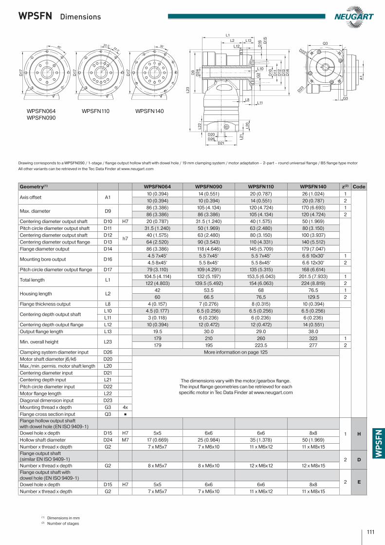
WPSFN Dimensions
Drawing corresponds to a WPSFN090 / 1-stage / flange output hollow shaft with dowel hole / 19 mm clamping system / motor adaptation – 2-part – round universal flange / B5 flange type motorAll other variants can be retrieved in the Tec Data Finder at www.neugart.com
Geometry(1) WPSFN064 WPSFN090 WPSFN110 WPSFN140 z(2) Code
Axis offset A110 (0.394) 14 (0.551) 20 (0.787) 26 (1.024) 110 (0.394) 10 (0.394) 14 (0.551) 20 (0.787) 2
Max. diameter D986 (3.386) 105 (4.134) 120 (4.724) 170 (6.693) 186 (3.386) 86 (3.386) 105 (4.134) 120 (4.724) 2
Centering diameter output shaft D10 H7 20 (0.787) 31.5 (1.240) 40 (1.575) 50 (1.969)Pitch circle diameter output shaft D11 31.5 (1.240) 50 (1.969) 63 (2.480) 80 (3.150)Centering diameter output shaft D12
h740 (1.575) 63 (2.480) 80 (3.150) 100 (3.937)
Centering diameter output flange D13 64 (2.520) 90 (3.543) 110 (4.331) 140 (5.512)Flange diameter output D14 86 (3.386) 118 (4.646) 145 (5.709) 179 (7.047)
Mounting bore output D164.5 7x45° 5.5 7x45° 5.5 7x45° 6.6 10x30° 14.5 8x45° 5.5 8x45° 5.5 8x45° 6.6 12x30° 2
Pitch circle diameter output flange D17 79 (3.110) 109 (4.291) 135 (5.315) 168 (6.614)
Total length L1104.5 (4.114) 132 (5.197) 153,5 (6.043) 201.5 (7.933) 1122 (4.803) 139.5 (5.492) 154 (6.063) 224 (8.819) 2
Housing length L242 53.5 68 76.5 160 66.5 76,5 129.5 2
Flange thickness output L8 4 (0.157) 7 (0.276) 8 (0.315) 10 (0.394)
Centering depth output shaftL10 4.5 (0.177) 6.5 (0.256) 6.5 (0.256) 6.5 (0.256)L11 3 (0.118) 6 (0.236) 6 (0.236) 6 (0.236)
Centering depth output flange L12 10 (0.394) 12 (0.472) 12 (0.472) 14 (0.551)Output flange length L13 19.5 30.0 29.0 38.0
Min. overall height L23179 210 260 323 1179 195 223.5 277 2
Clamping system diameter input D26 More information on page 125Motor shaft diameter j6/k6 D20
The dimensions vary with the motor/gearbox flange. The input flange geometries can be retrieved for each specific motor in Tec Data Finder at www.neugart.com
Max./min. permis. motor shaft length L20Centering diameter input D21Centering depth input L21Pitch circle diameter input D22Motor flange length L22Diagonal dimension input D23Mounting thread x depth G3 4xFlange cross section input Q3 ∎Flange hollow output shaftwith dowel hole (EN ISO 9409-1)
1 HDowel hole x depth D15 H7 5x5 6x6 6x6 8x8Hollow shaft diameter D24 M7 17 (0.669) 25 (0.984) 35 (1.378) 50 (1.969)Number x thread x depth G2 7 x M5x7 7 x M6x10 11 x M6x12 11 x M8x15Flange output shaft (similar EN ISO 9409-1) 2 DNumber x thread x depth G2 8 x M5x7 8 x M6x10 12 x M6x12 12 x M8x15Flange output shaft with dowel hole (EN ISO 9409-1)
2 EDowel hole x depth D15 H7 5x5 6x6 6x6 8x8Number x thread x depth G2 7 x M5x7 7 x M6x10 11 x M6x12 11 x M8x15
(1) Dimensions in mm(2) Number of stages
L1
G3
Q3
D22
L2 L13
L8
D20D26
D21
D9
D24 D10
D11
D12
D13
D14
G2
D16
L10
A1
L21
L20
L22
L23
D23
L12
L11
D17
D17
D17
45°22.5° 30°22.5°
D15
WPSFN064WPSFN090
WPSFN140WPSFN110
111