Embed Size (px)
Citation preview
Network Video Recorder - Alarm Server 3000 Series
RA Variants
Hardware Guide

THIS MANUAL WAS CREATED ON APRIL 21, 2010.
LEGAL CONSIDERATIONS LAWS THAT CAN VARY FROM COUNTRY TO COUNTRY MAY PROHIBIT CAMERA SURVEILLANCE. PLEASE ENSURE THAT THE RELEVANT LAWS ARE FULLY UNDERSTOOD FOR THE PARTICULAR COUNTRY OR REGION IN WHICH YOU WILL BE OPERATING THIS EQUIPMENT. INDIGOVISION LTD. ACCEPTS NO LIABILITY FOR IMPROPER OR ILLEGAL USE OF THIS PRODUCT.
COPYRIGHT COPYRIGHT © 2009 INDIGOVISION LIMITED. ALL RIGHTS RESERVED.
THIS MANUAL IS PROTECTED BY NATIONAL AND INTERNATIONAL COPYRIGHT AND OTHER LAWS. UNAUTHORIZED STORAGE, REPRODUCTION, TRANSMISSION AND/OR DISTRIBUTION OF THIS MANUAL, OR ANY PART OF IT, MAY RESULT IN CIVIL AND/OR CRIMINAL PROCEEDINGS.
INDIGOVISION IS A TRADEMARK OF INDIGOVISION LIMITED AND IS REGISTERED IN CERTAIN COUNTRIES. ALL OTHER PRODUCT NAMES REFERRED TO IN THIS MANUAL ARE TRADEMARKS OF THEIR RESPECTIVE OWNERS.
SAVE AS OTHERWISE AGREED WITH INDIGOVISION LIMITED AND/OR INDIGOVISION, INC., THIS MANUAL IS PROVIDED WITHOUT EXPRESS REPRESENTATION AND/OR WARRANTY OF ANY KIND. TO THE FULLEST EXTENT PERMITTED BY APPLICABLE LAWS, INDIGOVISION LIMITED AND INDIGOVISION, INC. DISCLAIM ALL IMPLIED REPRESENTATIONS, WARRANTIES, CONDITIONS AND/OR OBLIGATIONS OF EVERY KIND IN RESPECT OF THIS MANUAL. ACCORDINGLY, SAVE AS OTHERWISE AGREED WITH INDIGOVISION LIMITED AND/OR INDIGOVISION, INC., THIS MANUAL IS PROVIDED ON AN “AS IS”, “WITH ALL FAULTS” AND “AS AVAILABLE” BASIS. PLEASE CONTACT INDIGOVISION LIMITED (EITHER BY POST OR BY E-MAIL AT [email protected]) WITH ANY SUGGESTED CORRECTIONS AND/OR IMPROVEMENTS TO THIS MANUAL.
SAVE AS OTHERWISE AGREED WITH INDIGOVISION LIMITED AND/OR INDIGOVISION, INC., THE LIABILITY OF INDIGOVISION LIMITED AND INDIGOVISION, INC. FOR ANY LOSS (OTHER THAN DEATH OR PERSONAL INJURY) ARISING AS A RESULT OF ANY NEGLIGENT ACT OR OMISSION BY INDIGOVISION LIMITED AND/OR INDIGOVISION, INC. IN CONNECTION WITH THIS MANUAL AND/OR AS A RESULT OF ANY USE OF OR RELIANCE ON THIS MANUAL IS EXCLUDED TO THE FULLEST EXTENT PERMITTED BY APPLICABLE LAWS.

3
TABLE OF CONTENTS
ABOUT THIS GUIDE........................................ 5Safety Notices ........................................................... 5
1 CONFIGURATION ........................................ 7Overview ................................................................... 7Important Safeguards ................................................ 8
NVR-AS Power Up Sequence ............................. 8NVR-AS Power Off Sequence............................. 10
NVR-AS Usage ......................................................... 11Configuration ............................................................. 12
Using the Web Configuration Pages ................... 12Using the Serial Port Connection ........................ 19
Attaching the NVR-AS to the Network ...................... 21Further NVR-AS Configuration .................................. 21
2 HARDWARE DESCRIPTION .......................... 23NVR-AS Front View .................................................. 23NVR-AS Rear View ................................................... 25
Port Network Connectors .................................... 25Serial RS-232 Console Port ................................ 26Power .................................................................. 26
Rack-mounting your NVR-AS Unit ............................ 27Removable Disk Hardware ....................................... 28
3 USING THE REMOVABLE DISKS................... 29Changing Disks ......................................................... 29
Replacing a Faulty Disk ....................................... 31Protecting Recordings ............................................... 41Reformatting a RAID Array ....................................... 42

4
4 HARDWARE SPECIFICATION........................ 43Video .........................................................................43Audio .........................................................................43Storage ......................................................................43Network Connections ................................................43Performance ..............................................................44Metrics .......................................................................44Removable Disk Metrics ............................................45Environment ..............................................................45Regulatory .................................................................45
A GNU GENERAL PUBLIC LICENCE ............... 47

5
ABOUT THIS GUIDE
This guide is written for users of the Network Video Recorder - Alarm Server 3000 Series RA variants.
It provides detailed information about these devices, and a description of the hardware and specifications.
Note: “RAXXXX” denotes that the disks are arranged in a RAID array, with a disk capacity of XXXX GigaBytes.
For information on how to use the Web Configuration pages to configure the units, please see the Web Configuration Guide for the Network Video Recorder - Alarm Server 3000 Series.
Note: Where the term “NVR-AS” is used in this guide, it refers to all RA variants, unless otherwise specified.
Safety NoticesThis guide uses the following formats for safety notices:
Note: Additional information relating to the current section.
Caution: Potential hazard that could seriously impair operations.
Warning: Potential hazard that could damage the product or impair network function.

6

7
1 CONFIGURATION
OverviewThe Network Video Recorder - Alarm Server 3000 Series (NVR-AS) RA variants are rack-mountable or standalone video and audio recorders. They contain 4 disks organized as a RAID-0, RAID-1, or RAID-5 array, depending on the NVR-AS model, which allow you to store recordings and play them back at a later date. They provide a powerful and integrated recording and playback system for video and audio from cameras, transmitters, and receivers.
Each NVR-AS in a system can record from up to 64 cameras or transmitters while simultaneously playing back up to 20 recordings, all at full frame rate. Each NVR-AS is managed and configured by the Control Center application. Video can be played back to PCs, analog monitors and standard VCRs.
The NVR-AS allows you to do the following:
• Record video and audio streams from IndigoVision 8000 (MPEG4), IndigoVision 9000 (H.264), and IndigoVision 10000 (HD) units configured as transmitters; this can be on-demand, time scheduled, or event driven
• Play back video and audio streams to IndigoVision 8000 (MPEG4), IndigoVision 9000 (H.264), and IndigoVision 10000 (HD) units configured as receivers, or compatible PC software clients
• Manage recordings (deleting, scheduling, etc.)
• Log and report significant events
• Review the recordings and alarm events on the disks which are currently being recorded
• Review recordings and alarm events on an archived set of disks
• Prepare disks for recording

8
Important Safeguards• You must read all the safety and operating instructions before
using the product.
• You should adhere to all warnings on the product and in the operating instructions.
• Holes in the cabinet are provided for ventilation. These ensure reliable operation of the product and protect it from overheating. These openings must not be blocked or covered.
• This product should be operated only from the power source indicated on the label.
• Do not attempt to service this product yourself as opening or removing covers may expose you to dangerous voltages. Refer all service to qualified service personnel.
Caution: For continued protection against risk of fire, the mains fuse should only be replaced with same type and rating of fuse.
NVR-AS Power Up Sequence
Using the internal power supply1 Connect the mains input to the NVR-AS using the cable
provided. Switch on the mains power.
2 The NVR-AS now powers up and goes through its boot sequence. When the activity light (2nd from left as viewed from front) is regularly flashing the boot sequence is complete, and the NVR-AS is ready. The PS1 light should be lit to indicate the power supply is operating.

9
Using the external power supply
Note: The external power supply is not supplied with the product. You need to order it separately if required.
1 Ensure that the mains power is disconnected from the power supply.
2 Connect the circular DC power connector from the power supply to the NVR-AS ensuring that the mains power input to the power supply is still disconnected. Lock the connector in place by rotating the locking bush clockwise.
3 Connect the mains input to the power supply using the cable provided. Switch on the mains power.
4 The NVR-AS now powers up and goes through its boot sequence. When the activity light (2nd from left as viewed from front) is regularly flashing the boot sequence is complete, and the NVR-AS is ready. The PS2 light should be lit to indicate the power supply is operating.
Warning: The external power supply connector for the NVR-AS is of the same type as that for the IndigoVision 10-Channel Rack, however the voltages are different. Using the wrong power supply to power either the Rack or NVR-AS may result in damage to the unit and or power supply. Always ensure the correct power supply is used with the correct device.The power supply unit (PSU) connector for the NVR-AS has a locking screw mechanism, whereas the PSU for the Rack does not.

10
NVR-AS Power Off SequenceThe NVR-AS must be properly shut down before removing power.
To shut down the device:
1 Press the Suspend/Resume button on the front.
2 Wait until both the CPU and Alarm LEDs on the front panel change from solid on, to flashing.
3 Remove the mains power cable from the NVR-AS or power supply.
4 After removing mains power from an external power supply unit, remove the circular DC power connector from the NVR-AS. You must first unlock the locking bush — to do this, rotate it anti-clockwise.

11
NVR-AS UsageThe removable disks offer a flexible solution for recording and storing video footage. There are three main ways in which you can use the removable disks:
• Archiving disksYou can store the 4 disks as an archive. If you intend to do this, you must ensure that the disks are replaced when necessary. You should also protect all the recordings to effectively make the disks read-only before you archive them (see “Protecting Recordings” on page 41).
For information on removing and replacing disks, see “Using the Removable Disks” on page 29
• Reusing the same disksIf you do not need to store archive footage, you can record over old recordings. To do this, you should ensure that the appropriate disk space management regime is in force, for example, by setting up recording jobs to record at specific times.
Recordings are automatically reaped (deleted) when remaining disk space falls under a set threshold. In addition, you can specify that recordings should be deleted once they reach a certain age (see Chapter 3 for more information).
• Removing evidence of an incidentYou may need to remove disks containing footage of an incident for evidential purposes, and replace them to continue normal recording. Before removing the disks, you should ensure that all recordings are protected (see “Protecting Recordings” on page 41.)
For information on removing and replacing disks, see “Using the Removable Disks” on page 29
Warning: The order of the disks is important. Disks must be replaced in the same disk position from which they were removed, and must match the order of the disks on the web page (see Chapter 3 on page 29).As the four disks are combined in a RAID array, you cannot read data from a single disk in isolation.

12
ConfigurationYou can configure your NVR-AS using the Web Configuration pages or a serial connection.
Default IP PropertiesBy default, each NVR-AS is programmed with the following IP properties:
Using the Web Configuration PagesThis section takes you through the steps required to configure your NVR-AS using the Web Configuration pages. These are as follows:
1 Prepare an isolated network.
2 Prepare your PC for initial device configuration.
3 Configure your NVR-AS. This includes specifying its IP address and subnet mask.
Configuration PrerequisitesTo configure your NVR-AS using the Web Configuration pages, you require one of the following:
• A CAT5 crossover cable suitable for connection between the PC and the RJ45 connector on the NVR-AS
• An isolated hub or a switch
Table 1 Default IP Properties
Initial ConfigurationIP Address 10.5.1.10
Subnet Mask 255.0.0.0
Default Gateway 10.0.0.1

13
Step 1: Preparing an Isolated NetworkYou should connect your NVR-AS and the PC you are using to configure it on their own isolated network. To do this, use an Ethernet cross-over cable to connect the PC to either Ethernet interface on the rear of the unit (see Figure 1).
Figure 1 Connecting the NVR-AS and PC using a cross-over cable
Alternatively, you can connect the NVR-AS and PC to the same isolated hub or switch (see Figure 2):
Figure 2 Connecting the NVR-AS using an isolated hub/switch
PowerCat5 crossover
cable
PC
1 2 Console Port
NVR-AS
Isolated hubor switch
NVR-AS
Power
PC
1 2 Console Port

14
Step 2: Preparing PC for Initial Device ConfigurationAll NVR-AS units are supplied with their IP address set to 10.5.1.10 and their subnet mask set to 255.0.0.0. You cannot connect the devices to your network until you have changed these settings to suit your network.
To change the factory defaults of your NVR-AS, you must first (temporarily) modify your PC’s network settings.
Caution: Please make a note of the original value of all settings you change so that you can re-enter them when you have completed the initial device configuration.
To change your PC’s settings:
Use the Windows Network Settings configuration application to set the PC’s IP address and subnet mask.
1 In Windows Explorer, right-click My Network Places or Network Neighborhood, and select Properties.
2 Right-click Local Area Network and select Properties.
Figure 3 LAN Properties

15
3 Double-click Internet Protocol (TCP/IP).
Figure 4 IP Properties
4 Set the IP address to an address close to the factory IP address, for example, 10.5.1.2 and change the PC’s subnet mask to 255.0.0.0 (the same as the factory default).
5 Click OK, then OK again.

16
Step 3: Configuring your NVR-ASOnce you have changed your PC’s network settings, you must change the IP values of your NVR-AS from its factory defaults.
All NVR-AS units are supplied with their IP address set to 10.5.1.10 and their subnet mask set to 255.0.0.0. You cannot connect your device to the network until you have changed these settings to suit your network.
To configure a device using the Web Configuration pages:
1 Open a web browser. From the File menu, select Open, and enter 10.5.1.10 (the factory default IP address), then click OK.
2 The Web Configuration Home page appears. Figure 5 shows the home page for a RAID-5 device.
Figure 5 Web Configuration Home page (RAID-5 device)

17
3 Click Network in the menu on the left of the page.
Figure 6 Network page
4 Configure the device as required using the following fields.
• Host Name — Enter a name for the NVR-AS to identify the device.
• Location — Enter a location to identify the device.• IP Address — Enter the IP address of the unit’s Ethernet
port. • Subnet Mask — Enter the IP network subnet mask for the
Ethernet port.
Caution: Ensure that you enter the correct values. Once you change from the defaults, the device is no longer configurable by the PC with its current network settings.
• Ethernet Interface — Enter the link type used by the Ethernet port. The values are as follows:
• 100Mbps Half-Duplex
• 100Mbps Full-Duplex
• 1Gbps Full-Duplex
• Auto-negotiate

18
You may need to change the Ethernet link type default value from Auto-negotiate for some network devices. If you have problems maintaining a network link, contact your system administrator to determine the appropriate setting.
Caution: If the link type is changed from Auto-negotiate, your network switch must also be manually configured to the same network link setting.
• Gateway — Appropriate default gateway for remote network access: this is only required if the devices are to be accessed from a different subnet.
• Broadcast Address — This value is read-only, and is used by Control Center when scanning the network.
• Recording Stream — Select the stream you want to use for recording. This stream is then used for all recording jobs on this NVR-AS.
5 When you have configured the device as required, click Submit to apply the changes to the device. You are now ready to take your device off the isolated network and connect it to the main network. See “Attaching the NVR-AS to the Network” on page 21.
6 If you need to configure another device, disconnect the cable from the device. Leave the cable connected to the PC.
Note: You may want to make a note of the device’s new IP address and subnet mask, or label the device with its new details.
7 Connect the crossover cable to the next device you want to configure.
Note: Before you can access the next unit for configuration, you must type the following command from a Command Window:C:> arp -d 10.5.1.10
8 Repeat these steps for each device, using different IP addresses for each device.
Note: Ensure that no two devices share the same IP address (or that of the PC).

19
Using the Serial Port ConnectionTo configure your NVR-AS using its serial port, you require an RS232 serial cable.
1 Connect the serial cable between the NVR-AS and the PC.
Figure 7 Serial port connection
2 On the PC, use a Terminal Emulation program, e.g. Windows HyperTerminal, and set the serial port parameters as follows:
• 115200 baud• 8 bits• No parity• 1 stop bit• Flow Control: None
3 Connect to the unit and press <Enter>. You should see the following prompt:
NVR-AS 3000 RA2000 Version 3-12-0
Host Name : standaloneNVR
Location : unknown
Network : [ 10.5.1.10/255.0.0.0/10.0.0.1 ]
standaloneNVR login:
4 Log in to the unit using the username config and password config. The unit prompts you to enter the new configuration values. At each prompt, press <Enter> to accept the current value.
• IP Address — Enter the IP address of the unit’s Ethernet port.
Power
Serialcable PC
1 2 Console Port
NVR-AS

20
• Subnet Mask — Enter the IP network subnet mask of the Ethernet port.
• Gateway — Enter the appropriate default gateway for remote network access: this is only required if the devices are to be accessed from a different subnet.
• Link Type — Enter a link type for the Ethernet port. The values are as follows:
• 100Mbps Half-Duplex
• 100Mbps Full-Duplex
• 1Gbps Full-Duplex
• Auto-negotiate
You may need to change the Ethernet link type default value from Auto-negotiate for some network devices. If you have problems maintaining a network link, contact your system administrator to determine the appropriate setting.
Caution: If the link type is changed from Auto-negotiate, your network switch must also be manually configured to the same network link setting.
• Host name — Enter a name to describe the unit.
• Location — Enter a name to describe the location of the unit.
• Reset network security to factory defaults — To reset all network security values to their defaults, select yes. This includes any restrictions you have set up using the Network Security web page, such as the web password.
You are now ready to attach the NVR-AS to the network.

21
Attaching the NVR-AS to the NetworkAfter configuring the IP settings, you can connect it to the Ethernet network using a standard CAT5 Ethernet cable. Connect either port 1 or port 2 on the rear of the device to an Ethernet switch.
The NVR-AS has redundant Ethernet capability. If you connect both Ethernet ports to the network, and a link is not detected on one port, the NVR-AS automatically switches over to use the other port. To use this feature connect both ports to (preferably) different network switches (see Figure 8).
Figure 8 Connecting an NVR-AS to the network
Once you have connected your NVR-AS to the network, you can carry out further configuration.
Further NVR-AS ConfigurationYou can carry out further configuration of the NVR-AS using the Web Configuration pages. For more information, see the Web Configuration Guide.
Used forredundancy
NVR-AS
Power
PCNetwork
1 2 Console Port

22

23
2 HARDWARE DESCRIPTION
This chapter describes the hardware for the NVR-AS unit and the removable disks. It also provides information on rack-mounting the unit.
Warning: Do not attempt to service this product yourself as opening or removing covers may expose you to dangerous voltages. Refer all service to qualified service personnel.This apparatus must be earthed.To disconnect the device, ensure you follow the procedure on page 10.
NVR-AS Front ViewFigure 9 shows the front of the NVR-AS.
Figure 9 NVR-AS — front view
NVR-AS 3000
Suspend/Resume CPU
1 2
PS1 PS2
Disk 0 Disk 1
Disk 3 Disk 2
24
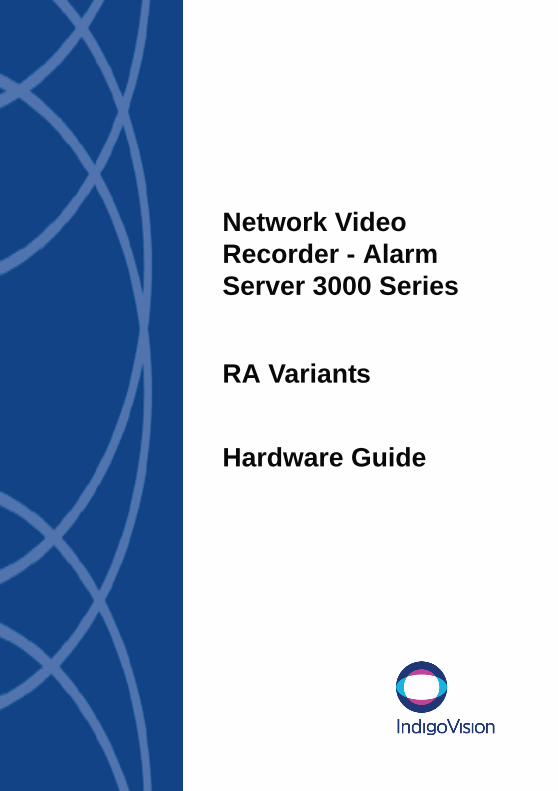
The LEDs on the NVR-AS report activity and status.
Table 2 Chassis LED description
LED Name Status MeaningCPU Solid off Normal operation
Solid on CPU processing is too high
CPU + Alarm Flashing NVR-AS suspended
Activity (server status) Flashing Normal operation
Solid on/off Server failure
Link Port 1 / Link Port 2 Flashing Network activity
Off No network link
On Network link present
Alarm Off Normal operation
On System failure
PS1 On Powered using internal PSU
PS2 On Powered using external PSU

25
NVR-AS Rear ViewFigure 10 shows the rear of the NVR-AS.
Figure 10 NVR-AS — rear view
At the rear of the unit, there are ports to connect to the following:
• Power
• Port 1 network connector
• Port 2 network connector
• Serial RS-232 console port
Port Network ConnectorsThe network connectors are RJ-45 connectors. These interfaces can be set to use fixed 100Mbps Half Duplex, 100Mbps Full Duplex, 1000Mbps Full Duplex link, or can be set to auto-negotiate. They are used to record and play back media streams, as well as for web page management.
Both ports should be connected to the network to provide Ethernet redundancy. Only one link will be active at any given time. If one links fails, the NVR-AS automatically switches to use the other, maintaining network connectivity using the same IP address.
1 2 Console Port

26
Serial RS-232 Console PortThe console port is an RS-232 interface, using the standard 9-pin DTE interface.
Note: Default console port settings are 115200 baud, 8-bits, no parity, 1 stop bit, no flow control.
PowerTwo power inlets are provided, a mains input to an internal power supply, and a DC input from an external power supply. The unit may be powered using either connector. Powering the unit through both connectors provides power supply redundancy so that if there is a failure in one supply, the unit can continue to operate from the other functioning power supply.
Warning: The external power supply connector for the NVR-AS is of the same type as that for the IndigoVision 10-Channel Rack, however the voltages are different. Using the wrong power supply to power either the Rack or NVR-AS may result in damage to the unit and or power supply. Always ensure the correct power supply is used with the correct device.The PSU connector for the NVR-AS has a locking screw mechanism, whereas the PSU for the Rack does not.
Table 3 Data Serial port pinouts
Pin RS232 Function1 —
2 Rx
3 Tx
4 —
5 GND
6 —
7 —
8 —
9 —

27
Rack-mounting your NVR-AS UnitIf you are rack-mounting your NVR-AS unit, please consider the following:
• Elevated Operating Ambient — If installed in a closed or multi-unit rack assembly, the operating ambient temperature of the rack environment may be greater than room ambient. Therefore, consideration should be given to installing the equipment in an environment compatible with the specified 50ºC maximum ambient temperature (Tma) of the unit.
• Reduced Air Flow — Installation of the equipment in a rack should be such that the amount of air flow required for safe operation of the equipment is not compromised. To facilitate this, an air gap of at least 6cm on both sides of the unit is recommended.
• Mechanical Loading — Mounting of the equipment in the rack should be such that a hazardous condition is not achieved due to uneven mechanical loading.
• Circuit Overloading — Consideration should be given to the connection of the equipment to the supply circuit and the effect that overloading of the circuits might have on overcurrent protection and supply wiring. Appropriate consideration of equipment nameplate ratings should be used when addressing this concern.
• Reliable Earthing — Reliable earthing of rack-mounted equipment should be maintained. Particular attention should be given to supply connections other than direct connections to the branch circuit (e.g. use of power strips).

28
Removable Disk HardwareThe NVR-AS uses a 3.5” SATA disk of various capacities in a removable drive enclosure.
Note: The disks used within any one NVR-AS must all be the same size.
Caution: The NVR-AS will start in a maintenance state if it detects an invalid RAID array; this may be because one or more disks are faulty/missing. No recordings will be made until you correct the disk problems, and (if necessary) format the RAID array.
Figure 11 shows the front of a removable disk.
Figure 11 Removable disk
Release Button Release Lever
Disk Lock

29
3 USING THE REMOVABLE DISKS
This chapter explains the following:
• Changing Disks
• Protecting Recordings
• Reformatting a RAID Array
Changing DisksThere are three occasions when you may need to change one or more NVR-AS disks:
• Replace a faulty disk.
• Replace all 4 disks and insert new ones. You need to replace the disks if they are becoming full according to your maintenance schedule, or if an incident has occurred and you need to remove them.
• Replace either the primary or secondary pair of disks in a RAID-1 NVR-AS. The primary and secondary pair of disks are a mirrored set in a RAID-1 NVR-AS, and hold the same recording data. You can remove either pair of disks to transfer recorded data to another NVR-AS. Once the pair of disks is replaced with new disks you can use the Disk web page to choose either of the following operations:
• to format the entire array erasing all recordings on all the disks, or
30
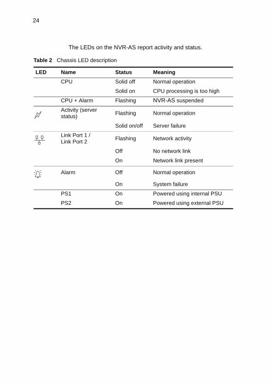
• to add the disks to the existing array which preserves the recordings and reinstates the RAID redundancy of the disks.
Warning: Disks have a warranty of 5 years, but this warranty will be voided if the disk is removed from the caddy.Disks are not field replaceable. Faulty disks must be returned to IndigoVision as part of a caddy assembly. Individual disk and caddy assemblies required as spares or replacements can be ordered from IndigoVision.
Caution: Before removing a disk set, IndigoVision recommends that you protect the recordings on the NVR-AS to prevent accidental deletion when it is re-inserted. For information on protecting recordings, see “Protecting Recordings” on page 41.It is essential that a removed disk is replaced into the same caddy from which it was removed, otherwise the RAID array will not be correctly rebuilt, resulting in a loss of recordings. IndigoVision recommends that you write the disk number (as shown on the web page) on the disks as you remove them from the NVR-AS, so as to note their position in the array.

31
Replacing a Faulty DiskThis section explains how to change disks. The procedure differs depending on whether you have a RAID-0, RAID-1, or RAID-5 NVR-AS.
Remove the front cover of the unit by turning the key to the unlock position and pulling the tab behind the lock.
RAID-0 NVR-ASWhen a disk fails on a RAID-0 NVR-AS, the RAID array crashes, all recording stops and all recordings are lost.
To replace a single disk that has failed:
1 Browse to the Home page of the unit — this may help identify which disk has failed.
Figure 12 RAID-0 NVR-AS with one disk indicating “Not Found”
2 Depending on the type of failure, one of the disks may indicate “Not found” — if so, this is the disk that has failed.
If all disks indicate NO RAID, please contact IndigoVision Partner Support. Please have information from the Diagnostics web page to hand.
32
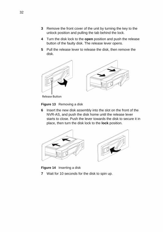
3 Remove the front cover of the unit by turning the key to the unlock position and pulling the tab behind the lock.
4 Turn the disk lock to the open position and push the release button of the faulty disk. The release lever opens.
5 Pull the release lever to release the disk, then remove the disk.
Figure 13 Removing a disk
6 Insert the new disk assembly into the slot on the front of the NVR-AS, and push the disk home until the release lever starts to close. Push the lever towards the disk to secure it in place, then turn the disk lock to the lock position.
Figure 14 Inserting a disk
7 Wait for 10 seconds for the disk to spin up.
Release Button

33
8 Browse to the Disk Configuration page and press Add Disk to recreate the RAID array with the new disk.
Figure 15 Disk Configuration page - RAID-0
9 The unit constructs the RAID array. Recordings recommence immediately.
The current status of the RAID array is shown both on the Home page, and the Disk Configuration page.

34
RAID-1 NVR-ASA RAID-1 NVR-AS consists of two pairs of disks. When a disk fails on a RAID-1 NVR-AS, one of the pairs of disks stops recording, but the other pair continues.
To replace a single disk that has failed:
1 Browse to the Home page of the unit — this may help identify which disk has failed.
Figure 16 RAID-1 Home page showing Disk 0 failure
2 Depending on the type of failure, one of the disks may indicate “Not found” or “Error” — if so, this is the disk that has failed.
If both disks indicate ERROR, please contact IndigoVision Partner Support. Please have information from the Diagnostics web page to hand.
3 Remove the front cover of the unit by turning the key to the unlock position and pulling the tab behind the lock.
4 Turn the disk lock to the open position and push the release button of the faulty disk. The release lever opens.
5 Pull the release lever to release the disk, then remove the disk.

35
Figure 17 Removing a disk
6 Insert the new disk assembly into the slot on the front of the NVR-AS, and push the disk home until the release lever starts to close. Push the lever towards the disk to secure it in place, then turn the disk lock to the lock position.
Figure 18 Inserting a disk
7 Wait for 10 seconds for the disk to spin up.
Release Button

36
8 Browse to the Disk Configuration page and click Add Disk to add the disk to the RAID array.
Figure 19 Adding disk to RAID-1 array
9 The unit adds the disk and rebuilds the RAID array. During the RAID rebuild, all disks are shown as rebuilding and the status line below the disks provides an estimate of how long this will take to complete. The rebuild time depends on the NVR-AS load. Recordings are not interrupted while the array rebuilds.
The current status of the RAID array is shown both on the Home page, and the Disk Configuration page.
Note: During rebuilding of RAID-1 disks, existing recordings remain intact.

37
RAID-5 NVR-ASWhen a disk fails on a RAID-5 NVR-AS it will continue recording until the failed disk can be replaced.
To replace a single disk that has failed:
1 Browse to the Home page of the unit - this may help identify which disk has failed.
Figure 20 RAID-5 Home page showing Disk 0 failure
2 Depending on the type of failure, one of the disks may indicate "Not found" or "Error".
3 Remove the front cover of the unit by turning the key to the unlock position and pulling the tab behind the lock.
4 Turn the disk lock to the open position and push the release button of the faulty disk. The release lever opens.

38
5 Pull the release lever to release the disk, then remove the disk.
Figure 21 Removing a disk
6 Insert the new disk assembly into the slot on the front of the NVR-AS, and push the disk home until the release lever starts to close. Push the lever towards the disk to secure it in place, then turn the disk lock to the lock position.
Figure 22 Inserting a Removable Disk
7 Wait for 10 seconds for the disk to spin up.
Release Button

39
8 Browse to the Disk Configuration page and click Add Disk to add the disk to the RAID array.
Figure 23 Adding disk to RAID-5 array
9 The unit adds the disk and rebuilds the RAID array. During the RAID rebuild, all disks are shown as rebuilding and the status line below the disks provides an estimate of how long this will take to complete. The rebuild time depends on the NVR-AS load. Recordings are not interrupted while the array rebuilds.
The current status of the RAID array is shown both on the Home page, and the Disk Configuration page.
Note: During rebuilding of RAID-5 disks, existing recordings remain intact.

40
Replacing all Four Disks
Caution: It is advisable to protect all recordings before removing all four disks.
1 Browse to the Diagnostics page and click Shutdown.
2 Wait for the web page to confirm that the shutdown has completed.
3 Power off the unit.
4 Remove each disk in turn, noting its position in the RAID array to ensure that it is returned to the same position at a later date.
5 Insert each new disk in turn, ensuring each disk is locked, and if these disks are from a previously archived set, that they are replaced in the correct position.
6 Power on the unit.
7 If this is a new set of RAID array disks, or you wish to start with a clean RAID array, browse to the Disk Web Page and click Format Entire RAID Array. This re-partitions, formats and builds the RAID array.
Warning: When you click Format Entire RAID Array, all existing recordings on the disks are deleted.

41
Protecting RecordingsIt is good practice to set all recordings on the disks to protected status before removing a disk set which is to be archived. This means that when the disks are reinserted, recordings cannot be accidentally deleted or recorded over.
Caution: Please be aware that if you protect all recordings, you lose the ability to identify recordings that were deliberately protected by the user in Control Center.
To protect all recordings on the disks:
1 Enter the IP address of the NVR-AS containing the disk into the URL field of a web browser.
2 Click Disk in the menu on the left. The Disk Configuration page opens.
Figure 24 Disk Configuration page
3 Click Protect All to protect all recordings and events on the current disks. (Similarly, click Unprotect All to allow all recordings and events to be deleted.)
4 Click Submit.
42
Reformatting a RAID ArrayTo format the current disks, and build a clean RAID array, erasing any previously stored data:
1 Browse to the Disk Page.
2 Click Format Entire RAID Array.
3 Confirm that you wish to format the RAID array.
The RAID array is formatted and the NVR-AS commences normal operation.
The RAID array continues a background rebuild operation to establish disk redundancy. The time taken to complete this will depend on the NVR-AS recording load.
Warning: All data on the disks is erased when you format the RAID array.

43
4 HARDWARE SPECIFICATION
Video • Recording and playback of HD streams from IndigoVision 10000 transmitters and receivers.
• Recording and playback of H.264 streams from IndigoVision 9000 transmitters and receivers.
• Recording and playback of MPEG4 Simple Profile streams from IndigoVision 8000 transmitters and receivers.
• H.261 video streams can be recorded and played back using IndigoVision 6000 transmitters and receivers running firmware version 4 and later.
Audio Recording and playback of AAC-LC audio codec streams from IndigoVision 8000, 9000 and 10000 transmitters and receivers.• Audio streams from IndigoVision 6000 transmitters and
receivers can be recorded and played back using IndigoVision 6000 devices running firmware version 4 and later.
StorageVarious disk capacity options are available. Please refer to the IndigoVision price list for full details.
Network Connections• IEEE 802.3 and IETF standards:
• 100BaseT, 1000BaseT Ethernet, TCP, UDP, ICMP and IGMP
• Physical connection via RJ-45
44
Performance
The NVR-AS may permit these maximum settings to be exceeded but at the risk of impairing its overall function.
Metrics
Dimensions• 483mm x 88mm x 272mm
Weight• 8.2Kg (max), with 4 disks
Power• Operating Voltage
• Input 100-240V ~ 47-63Hz 1A
• Power consumption: 53W max
Feature MaximumRecording Streams 64 (RAID-0)
64 (RAID-1)40 (RAID-5)
Recording Bandwidth 40 Mbps
Configured Recording Jobs 100
Total Number of Recordings 40,000
Number of Alarms 100,000
Playback Streams 20*
Playback Bandwidth 20 Mbps* A playback stream is required for displaying thumbnail images and carrying out motion search in Control Center
45
Removable Disk Metrics
Dimensions• 102mm x 147mm x 26.1m
Weight• 1TB - 0.665Kg
• 500GB - 0.53Kg
Environment• Operating temperature 0 to +50°C/+32 to +122°F
• Storage temperature -20 to +70°C/-4 to +158°F
Regulatory• EN55022 ITE Emission standard Class A
• EN61000-3-2 Mains Harmonics Class A
• EN61000-3-3 Voltage Fluctuation
• EN55024 ITE Immunity standard
• UL 60950-01, Information Technology Equipment - Safety - Part 1: General Requirements
• CFR47: 2005 Part 15 Sub Part B (US federal code of regulations)
In accordance with the EC Waste Electrical and Electronic Equipment (WEEE) directive 2002/96/EC this product must be sent to a recycling plant for proper disposal at the end of its use.

46

47
A GNU GENERAL PUBLIC LICENCE
IndigoVision's products use code that is freely available under the General Public Licence (GPL).
This licence makes it a requirement to release changes made to the source code. In compliance, the GPL source code and any changes made by IndigoVision are available on request through IndigoVision Customer Support.

48

49
INDEX
Aarchiving disks 11audio specification 43
Cchanging removable disks 29
warnings 30configuration
initial 12prerequisites 12using serial port 19using Web Configuration
pages 12configuring basic settings 16connectors
network 43power 26serial port 26
console port 26
Ddimensions
NVR-AS 44removable disks 45
Eenvironmental specification 45Ethernet redundancy 25evidence, storing 11
Fformatting removable disks 42front view 23
Ggeneral public licence 47
Hhardware
NVR-AS 23removable disks 28specification 43
Iinitial IP properties 12IP properties 12
changing 16changing using serial port 19
isolated network, preparing 13
Kkey
removable disks 28
LLEDs
NVR-AS 24removable disks 28
Mmetrics 44, 45modifying PC network settings 14
Nnetwork connections 43NVR-AS
attaching to network 21changing defaults 16configuration 12dimensions 44front view 23hardware 23LEDs 24

50
rack-mounting 27rear view 25usage 11
PPC network settings
modifying 14performance maximums 44power connector 26power off sequence 10power supply, NVR-AS vs Rack 9,
26power up sequence 8preparing isolated network 13prerequisites for configuration 12protecting recordings 41
Rrack-mounting NVR-AS 27RAID array 11
rebuilding 33reformatting 42
rear view 25rebuilding RAID array 33recordings
protecting 41unprotecting 41
reformatting RAID array 42regulatory specification 45removable disks
archiving 11changing 29dimensions 45formatting 42hardware 28inserting 32LEDs 28removing 11replacing all 40replacing single disk 31, 34reusing 11uses 11
removing disks 11reusing disks 11
Ssafety warnings 8serial RS-232 console port 26specifications
audio 43environmental 45regulatory 45storage 43video 43
storage specifications 43storing evidence 11
Uunprotecting recordings 41usage of NVR-AS 11
Vvideo specification 43
Wwarnings, when changing disks 30Web Configuration pages 12

51

Document ID: IU-NVR-RA-MAN010-2