Embed Size (px)
Citation preview

FTD-RL29 742 ARMY PACKET RAHDIO NETWORK PROTOCOL STUDY(U) SRI /I INTERNATIONAL MENLO PARK CA D E RUBIN NOY 77I SRI-TR-2325-i43-i DRHCi5-73-C-8i87
p UCLASSIFIED F/G 07/2. 1 L

'44
.25I
MICROCOPY RESOLUTION TFST CHART
NAT ONAL BUREAU Cf STINDRES 1% l A
I
" S2 5 0 0 S _S S S
ARMY PACKET RADIONETWORK PROTOCOLSTUDY
CA Technical Report 2325-143-1
e November1977
By: Darryl E. Rubin
Prepared for:
U,S. Army Electronics CommandFort Monmouth, New Jersey 07703
Attn: Mi. Charles Graff, DRDCO-COM-RF-4
Contract DAHC 1 5-73-C-01 87
SRI Project 2325
* 0. The views and conclusions contained in this document are those ofauthor and should not be Interpreted as necessarily representing th
Cofficial policies, either expressed or implied, of the U.S. Army or the.LJ United States Government.
-.*m
333 Ravenswood Ave. * Menlo Park, California 940250 (415) 326-6200 e Cable: STANRES, Menlo Park * TWX: 910-373-1246
83 06 '03 .

4 qUNCLASSIFIEDSECURITY CLASSIFICATION OF THIS PAGE (When Data Entered)
READ INSTRUCTIONSREPORT DOCUMENTATION PAGE BEFORE COMPLETING FORM
1 REPORT NUMBER 2. GOVT ACCESSION NO 3 RECIPIENT'S CATALOG NUMBER[" 2~~1325-143-1 / )r -. : i'/ -
4. TITLE .and Subtitle) 5- TYPE OF REPORT & PERIOD COVERED
Army Packet Radio Network Protocol Study Technical Report
6. PERFORMING ORG. REPORT NUMBER
7 AUTHOR(s)A 8 CONTRACT OR GRANT NUMBER(s)
Darrvl E. Rubin DAHCI5-73C-0187
9. PERFORMING ORGANIZATION NAME AND ADDRESS 10. PROGRAM ELEMENT, PROJECT. TASK
AREA & WORK UNIT NUMBERS
SRI International Program Code N. P62708E
333 Ravenswood AvenueMenlo Park, California 94025 12. REPORT DATE 13. NO. OF PAGES
11. CONTROLLING OFFICE NAME AND ADDRESS November 1977
U. S. Army Electronics Command 15. SECURITY CLASS. (of this report)
Fort Monmouth, New Jersey 07703
Attn: Mr. Charles Graff, DRDCO-COM-RF-414 MONITORING AGENCY NAME & ADDRESS (if diff. from Controlling Office)
15a. DECLASSIFICATION/DOWNGRADINGSCHEDULE
16. DISTRIBUTION STATEMENT (of this report)
17. DISTRIBUTION STATEMENT (of the abstract entered in Block 20, if different from report)
18. SUPPLEMENTARY NOTES
19. KEY WORDS (Continue on reverse side if necessary and identify by block number)
Packet radio network, TIDS, TACFIRE, experimental Bay Area PRNET, TCP,communication protocols, Army Message Protocol (AMP), host interface unit.
20. ABSTRACT (Continue on reverse side if necessary and identify by block number)
This report presents the results of an Army Packet Radio Network (PRNET)Communication Protocol Study. Tactical Information Distribution System (TIDS)data communication requirements are analyzed and discussed, and a set of PRNETcommunication protocols that satisfies those requirements is defined. A generalstrategy for attaching a PRNET to TACFIRE is presented, and an application-levelprotocol is specified to make the replacement of the VHF-FM communication
equipment with packet radio equipment transparent to the rest of the TACFIREsvstem.
DD 1 OR 1473 UNCLASSIFIED
EDITION OF 1 NOV 65 IS OBSOLETE SECURITY CLASSIFICATION OF THIS PAGE (Whei Data ntiredI

4
CONTENTS
LIST OF ILLUSTRATIONS ........... iii
PREFACE ............. iv
I INTRODUCTION............
II PACKET-SWITCHED COMPUTER NETWORKS
III THE ARPA PACKET RADIO NETWORK. . ........ . 8
A. The Channel Access Protocol ... ....... .. 10
B. Station-to-PRU Protocol ... . . . . .... 14
C. Transmission Control Protocol ... ........ 15
D. TCP and User Processes ........... 15
E. TCP Mechanisms ....... ......... 17
IV THE PRNET IN MILITARY APPLICATIONS ... ........ 21
A. Attachment to TACFIRE ...... ........... 21
B. Army PRNET Communication Protocols .... ....... 24
4 V THE ARMY MESSAGE PROTOCOL ... ...... o.. . 30
A. AMP Specification .. . ... I 30
B. AMP Process Interface....... . . /. . 37
C. Analysis of AMP. ... . . . . ...... 38
VI SUMMARY ............ .. 41
REFERENCES........ .... ... . 42
ii ,
.1 ~'.

ILLUSTRATIONS
1 Overview of Current TACFIRE Configuration .... .... 2
2 Typical Computer Network ...... ... ........ 5
3 Message Transmission by Packet Switching. ...... . 7
4 Packet Radio Network Logical Diagram. ..... . . . 9
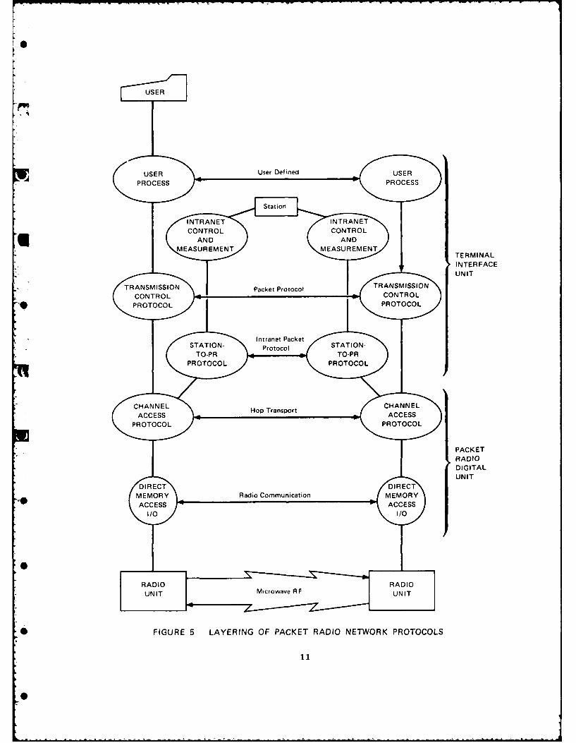
1 5 Layering of Packet Radio Network Protocols ...... 11
6 Format of PRNET Packet ... .... ...... 12
7 Format of Internet Packet ..... ..... .. 18
* 8 Proposed TACFIRE Communication Structure ....... .23
9 Proposed PRNET Protocol Structure for TACFIREApplication ..... ........ 25
10 Host Interface Unit Process Structure . . ...... 27
11 Proposed Intranet Naming Convention . ....... 28
12 Format of AMP Header ... .... ...... 32
13 Format of Association State Block. ...... ... 34
iii

M
PREFACE
There are enormous unfulfilled needs in the military for datacommunication at all levels, tactical and strategic, owing largely tothe proliferation of computer-based systems. These needs are becomingwell recognized; for example, the Army is aware of the emergingrequirements for tactical information distribution systems (TIDS) thatcan serve the artillery, tanks, intelligence, air defense, logistics,and other tactical components. Current tactical systems, such as theAN/VRC-12 VHF-FM radio and the AN/TRC series of multichannel voiceradio, are unable function effectively in this capacity. However, witnthe advanced computer communication technology now available and underdevelopment, which encompasses virtually all media (land lines,satellite, ground radio), it appears that powerful and flexible TIDSsolutions can be achieved. The experimental packet radio network(PRNET), which has already demonstrated a powerful internetworkcapability through its interconnection with the ARPANET, employs such atechnology.
The Army is currently evaluating the possibility of utilizing theTactical Fire Direction System (TACFIRE) in a TIDS testbed. TACFIRE'scommunication structure suggests that it might be desirable to introducepacket radio TIDS technology to the TACFIRE system. This could beachieved by substituting a single (shared) broadband PRNET for theseveral (dedicated) narrowband VHF radio nets now being used, anapproach applicable to any TIDS. For compatibility, such a substitutionof communication media must be transparent to the existing communicationprotocols and software, as well as to those components not replaced bythe packet radio equipment.
The purpose of this report is to recommend a communication protocolstructure for use within military PRNETs that will fulfill thecommunication requirements of TACFIRE and other Army tactical datasystems while requiring minimum modification to these systems. (While
-. this approach cannot take full advantage of the increased power ofinternetwork computer communication, it is a first step in providing theArmy with a modern data communication system.) The proposed protocolstructure makes use of the ARPA-developed transmission control protocol(TCP) for all internet and intercommand center message exchanges, and anew Army message protocol (AMP) specifically designed for the low-level
* TIDS environment, for message exchange among remote terminals, andbetween the remote terminals and command centers. To minimize changesto the user components, an application protocol (MSGMUX) is defined tomediate the transfer of messages between the user equipment and thePRNET equipment without modifications of any sort to the messages ormessage-flow patterns.
I
iv
I

This report also proposes a strategy for attachment of a PRNET to aspecific user system, the Army Tactical Fire Direction System (TACFIRE),to replace the VHF FM communication equipment currently in use. Thiswill be done by interfacing PRNET host interface units (HIUs) to theTACFIRE components at a bus level where such attachment can be made withno effect on other components, while permitting access to all TACFIREmessage flow. At the TACFIRE fire direction centers (FDCs), thisproposed attachment will be made at the digital data terminal (DDT)level, displacing the DDTs. At the remote terminal level, the HIU willbe interfaced to the internal bus of the terminal device, and anyspecial input/output transformations necessary for the success of suchattachment will be implemented within the HIU to avoid modification toTACFIRE terminal software.
U TACFIRE was chosen as a test system for the introduction of PRNETcommunication technology since it is the most developed computer-basedmilitary system available; it is therefore well established, and hasmuch available documentation. All recommendations in this reportregarding TACFIRE or general military communication are purelypreliminary; they are intended as bases for further design and analysis
. pending further investigation and initial testing of military PRNETcommunication systems.
v

I INTRODUCTION
The Army tactical fire direction system (TACFIRE) [1)0 is acomputer-assisted command and control system for the direction oftactical fire support. Its objective is to automate the integration offactors of strategy, tactics, intelligence, communication, and logisticsin order to increase fire support effectiveness, by improving accuracy,reaction time, use of target information, and allocation of fire.TACFIRE automates the functions of the battalion and division artilleryfire direction centers (FDC), as well as those in the division firesupport element (FSE), including fire unit and ammunition status,meteorological data, nonnuclear fire planning, target intelligence,tactical and technical fire control, survey information, preliminarytarget analysis, nuclear target analysis, nuclear fire planning,chemical target analysis, and fallout prediction.
Figure 1 summarizes the TACFIRE configuration and identifies the
system components. TACFIRE currently uses VHF FM communicationchannels, with access by contention; such radio links suffer severaldeficiencies, especially in data transmission applications, including:
Functional incompatibility: The VHF radios were designed forspeech rather than data traffic; selected units and repetitivefield adjustments are required to achieve operatingcharacteristics suitable for data transmission.
Low bandwidth: Currently, the maximum data transfer rate perlogical communication path is 1200 baud (less with coding).
Low reliability: Data error rates are undesirably high,requiring excessive retransmission of messages.
Susceptibility to interference: Narrowband communication linksare easily disrupted by channel contention and random backgroundinterference (e.g., multipath), as well as by deliberate jammingand spoofing.
Susceptibility to interception: The VHF FM radio signals areeasily intercepted by the enemy for purposes of locating andhoming in upon TACFIRE installations.
Low sharing capacity: Contention access limits the number of
* References are listed at the end of the report.
6

KcC>c-
-C Z
CL 2v -a
.. E
c ! CL wO~O
C C
2 E - - 'D -0 E w
C)~ Sa cm E . C
m oN0 w 2.o -3 CW0
LL~ Ca LUw a
~. '!~ 0
U-z
c Zz zz L
Lu LL L L
z
cr 0
a WU
LU w 0
zi
u C) (L) 0 D~I>< >F- NOOLb
60 Ua) -
VL
U.to E2

0
users sharing a single radio link. This contention necessitatesa large number of manually configured physical nets usingseparate channels, engendering communication inflexibilitythrough difficulties in internet communication and physical netreconfiguration.
Manual operation: The operation of the radio equipment andconfiguration of the communication nets must be done manually, aserious source of inefficiency and inflexibility in a computercommunication environment.
TACFIRE would greatly benefit from a more sophisticated
U communication medium free of the above problems, and offering enhancedreal-time flexibility and user capacity, as well as a capability forinternet interaction with other military data systems. The state-of-the-art packet radio technology can provide this kind of performance[2].
The purpose of this report is:
(1) To show how military systems (specifically TACFIRE) couldbenefit from employment of packet radio technology.
(2) To recommend a set of PRNET protocols that fulfill theneeds of general military data communication.
(3) To propose an approach for interfacing a PRNET to theTACFIRE system for the implementation of the Army PRNETprotocols.
Information about packet switching in general and the current PRNETtechnology and protocols is presented as background in the following twosections.
-I
6

II PACKET-SWITCHED COMPUTER NETWORKS
Computer networking technology arose from the need to sharedistributed computer resources, notably data bases, data storagefacilities, and hardware and software computing facilities [3]. Tomake the resources of a set of computer systems and stand-aloneterminals mutually accessible, a communication medium is required tomediate the exchange of control and data traffic between sites. Controltraffic is used to request and regulate the access to remote resources,
while data traffic carries the user-level information between sites foruse by the acquired resources.
The communication medium provided for computer interaction must becapable of rapidly and dynamically establishing and reconfiguringlogical traffic paths through the network in response to user needs or
"I the outcome of on-going processing tasks. These paths must be highbandwidth, and provide for a reliable and efficient exchange of controland data traffic that is insensitive to local failures in the networkcommunication equipment.
Figure 2 illustrates a typical computer network. The networkconsists of several computer systems, called hosts, and a set of stand-alone intelligent terminals; also shown are two teletypes interfaced tothe network through a special terminal access multiplexer. Theseelements are all interfaced to what is known as the subnet, which servesas the common communication medium described above. Through the subnet,users at stand-alone terminals and at host terminals, as well asautomated functions (processes) within the hosts themselves, can accessand utilize any network host resources that are made available to thenetwork.
The high performance requirements of the subnet normallynecessitate an architecture consisting of computer-based switchingnodes. Such an intelligent subnet can optimally route traffic throughthe network depending upon its type (critical or noncritical, control ordata), automatically accounting for instantaneous global and localoperational and failure conditions, and monitoring and ensuring theintegrity of the transferred data.
Internode communication within the subnet may occur on multiplexedradio or landline links, but the dedication of an end-to-end (ETE) chainof link slots (a "circuit") to a single traffic path is unacceptable incomputer communication applications for three reasons:
I4

HOST PERIPHERALS
PRINTER
TELETYPE DS
~~HST/
COMPUTER
HARDWARE AND
SOFTWARE
14 SUBSCRIBER
HIGH BANDWIDT H N ER A E
•PORTS
DALINKS
TERMINAL
ACCESSMULTIPLEXER
~HOST
COMMUNICATION
DIS
14
TELETYPE
FIGURE 2 TYPICAL COMPUTER NETWORK
5
14

I
The nuriber of active logical traffic paths Is potentially muchlarger than the number of available circuits.
Computer communication is very bursty, so the peak bandwidth ismuch higher than the average bandwidth. Dedicating a circuit toa single traffic path would promote poor channel utilization.
Effective computer interaction requires minimum ETE messagedelay. The time required to reserve, set up, and releasecircuits would degrade overall ETE performance.
In a subnet specifically designed for computer communication, slotsare further multiplexed at the software level by chopping trafficstreams into "packets," and switching link slot assignment among thetraffic from several streams; this is known as packet switching.Division of information into packets normally occurs at the entrance tothe subnet; packets on a given traffic path are individually forwardedfrom node to node toward their destination along the best route thatavoids nonfunctional nodes, and reassembled with ETE error checking intoa contiguous stream at the subnet exit (see Figure 3). To aidsequencing, routing, and control of packets within the subnet, a headeris appended to each packet at the subnet entry, anu removed at thesubnet exit. One example of a packet-switching node that operates inthis fashion is the ARPANET interface message processor (IMP) [41.
Communication protocols are needed to realize the potentials of apacket-switching subnet--to mediate traffic stream fragmentation andreassembly, routing, and ETE error checking, as well as to facilitatehigher-level remote resource access functions; these protocols consistof globally understood sequences of control messages, and usually existin a hierarchical structure. At the lowest level is the node-to-nodeprotocol that uses the packet header information to forward a packetthrough the subnet from source to destination. Calling upon this levelare the host-to-host and terminal-to-host protocols, which facilitatecommunication among the set of hosts and terrinals by ensuring reliableand properly sequenced ETE information exchanges. At the highest
* process-to-process level, protocols directly bring about and regulateaccess to the remote network resources (such as files) through normalinterprocess control mechanisms. Such a hierarchy of communicationprotocols can render the details of network operation and access fullytransparent, provide for fully reliable information exchange, andfacilitate simplified, flexible utilization of the distributed networkresources.
I
[6

0
PROCESS
HOSTL MESSAGE
NET INTERFACE
1 -PACKETS OF MESSAGE
3a SUBNET
-I-PACKETS OF
MESSAGE, POSSIBLY
OUT OF ORDER
NET INTERFACE
RECONSTITUTEDflMESSAGE
*USER HOSTPROCESS
FIGURE 3 MESSAGE TRANSMISSION BY PACKET SWITCHING
7

I
III THE ARPA PACKET RADIO NETWORK
The ARPA Packet Radio Network (PRNET) combines packet-switchingtechniques with advances in microwave and microprocessor technology toprovide a system for mobile digital communication and data distributionusing radio channels. The radio technology being utilized is inherentlyresistant to jamming, spoofing, and detection. An experimental PRNET iscurrently being tested In the San Francisco Bay Area, with repeaternodes located at selected sites to provide coverage of much of the BayArea.
A logical diagram of a PRNET is shown in Figure 4. The primarycomponent at each subnet node in the PRNET is the packet radio unit(PRU). Each PRU contains an L-band microwave spread-spectrum radio unitfor transmitting and receiving packets at either of two rates (100 and
. 400 kbits/s), and a microprocessor-based digital unit that implementsthe node-to-node protocol for controlling the routing and flow ofpackets between the PRUs. A PRU may operate stand-alone as a repeater,or may be attached to a computer system (host) or terminal interfaceunit (TIU) through a special digital (1822) interface [5]; thisinterface is the portal through which all packets enter and leave thenetwork.
PRNET nodes are logically organized into a hierarchy determined bytheir radio "distance" (number of radio hops) from a special node, thestation; the station is at Level 0, PRUs in direct contact with thestation are at Level 1, PRUs that require one repeater hop to contactthe station are at Level 2, and so on. The station consists of a PRUattached to a station processor (a PDP-11/40 in the SRI testbed); it isthe site of centralized network control, and is responsible for
" monitoring of overall network connectivity, route assignment, andupdating of remote PRU operating and data base pzrameters [6]. In avery hostile environment, multiple cooperating stations can be deployedat different sites within the network to provide fail-soft operation.The PRNET is therefore unlike other computer networks (such as theARPANET) wherein network control functions (e.g., routing) aredistributed, and accordingly is not susceptible to network-widedisruption of these functions as a result of improper node behavior.
The radio connectivity that determines the exact hierarchicalstructure of the PRNET at any moment is primarily a function of thegeographic separation and terrain environment of the PRUs. Since PRUscan be mobile (and can fail), the logical configuration of the networkcan change dynamically; however, since network control is automated bythe station, these topological changes are transparent to the network
8

0
HIERARCHY
LEVEL
STATION
PACKET 0RADIOUNIT
PACKE STATION
URADIO PROCESSOR TERMINALUNIT PACKET
REPA E T RADIO
TEERMINAL
PACKET PACKET RADIORADIO RADIO UNITUNTUI REPEATER
I HOS I / TELETYPE
UNITLELETYP
FIGURE 4 PACKET RADIO NETWORK LOGICAL DIAGRAM
9

users, whose processing tasks can continue uninterrupted even in theface of major network reconfiguration and distributed node failures. To
F, ensure such robust operation is the function of the severalcommunication protocols implemented within the PRNET nodes, station,
*- TIUs, and hosts. These include:
• Channel Access Protocol (CAP)
* Station-to-PRU Protocol (SPP)
• Transmission Control Protocol (TCP).
This protocol layering is shown in Figure 5. The protocols arediscussed in the sections that follow.
A. The Channel Access Protocol
* CAP [7], which is implemented by the digital section of each PRU,provides the basic mechanism for packet transport from node to nodewithin the PRNET. It performs functions of radio channel access, packetrouting, hop-by-hop retransmission, and system monitoring. It makes useof a packet header (PRNET header, Figure 6), which is supplied by thepacket source and removed at the packet destination; the header containsthe addressing, sequencing, routing, and control information needed byCAP. PRNET packets are 11 to 127 16-bit words long, the first 11 ofwaich are reserved for the PRNET header; an additional 32-bit cyclicreJundancy checksum (CRC) is appended to the packet by CAP at the subnetentry for detection of radio transmission bit errors.
1. Radio Channel Access
A PRU can access the radio communication channel in either oftwo ways, as determined by a control message from the station. In theALOHA mode [8], packets are transmitted spontaneously, risking packetcollisions from simultaneous channel access, and an acknowledgment ofcorrect receipt by the next node is awaited. If the acknowledgment doesnot arrive within a specified time interval, the packet is presumedlost, and retransmitted after a randomized time-out interval (to preventrepetitive collisions). (Of course, lost packets may actually have beendiscarded by the receiving node owing to bit errors, but this is of no
• import to the sender.) In the carrier-sense mode [9], PRUs wait untilthe radio channel is idle before transmitting a packet, improvingchannel utilization by avoiding collisions (since the packettransmission time is only a few milliseconds, PRUs normally wait no morethan tens of milliseconds to transmit a packet when there is channelcontention).
10
rUS ER
USER Usr DTERMINALE
(:PROCOL POCS
INTRANETIRADIOE
DERMITAL
UNIT
* IGRE5LAERNROOPCETRACONTWR PROTOCOLS
Inrne 1ace
STTO -PooclSAIN

6
16 BITS
HEADER LENGTH PACKET LENGTH
SOURCE IDENTIFICATION
DESTINATION IDENTIFICATION
SEQUENCE NUMBER
SPP PACKET IDENTIFICATIONAND FUNCTION
WORKING HOP COUNT PRNET HEADER
RESERVED FOR MEASUREMENT
PACKET ROUTE WORD 0
ROUTE WORD 1
ROUTE WORD 2
ROUTE WORD 3
0-116 DATA WORDS
CYCLIC32-BIT REDUNDANCY CAP TRAILER
CHECKSUM
FIGURE 6 FORMAT OF PRNET PACKET
4
12

2. Rout ing
The PRNET currently employs a centralized routing algorithm,which requires minimal routing table space at each node. The stationassigns a logical address (label) to each node, and a route along whichit will forward packets to the station. Assigned routes always carrypackets one hierarchy level closer to the station with each hop; whenthe packets arrive at the station, they are forwarded along an outboundroute (chosen by the station), which carries them one level further fromthe station with each hop until they arrive at the destination node.The PRNET header contains space for the list of logical addresses alongthe attached packet's route.
3. Hop-by-Hop Retransmission
Packets may be lost a. they travel between nodes; possiblecauses include packet collisions resulting from channel contention,sudden connectivity changes, and random fluctuations in ambient noiseand propagation conditions. To improve the probability of successful
q1 multihop transport, CAP performs hop-by-hop retransmission and positiveacknowledgment. When a PRU forwards a packet, it saves a copy, which itwill retransmit at a later time unless it receives an acknowledgment ofcorrect receipt of the packet; this acknowledgment is implicit if thePRU hears the packet being forwarded at the next hop, and explicit ifonly the packet's header is transmitted (explicit acknowledgments areused at the last hop, from which a packet is not forwarded, and at a PRUthat is transmitting and receiving at different bit rates).Retransmissions can recur any number of times up to a set maximum, afterwhich the PRU will discard the packet; because CAP (and consequently thepacket radio subnet) does not guarantee packet delivery, reliabilitymust be ensured by higher level protocols.
4. System Monitoring
Because of the dynamic variability of the PRNET's physical andlogical configuration, each PRU periodically announces its presence tothe station by emitting special "repeater-on" packets (ROPs). Any nodethat receives a ROP enters its own label into the packet header andforwards the packet toward the station. This mechanism provides thestation with a record of all active PRUs at a given moment, and all theroutes that lead to them. This information allows the station tomaintain its network connectivity and routing tables, automaticallyupdating them whenever existing nodes change or lose connectivity, andwhenever new nodes establish connectivity.
13

B. Station-to-RU Protocol
The SPP [10] is an ETE protocol designed specifically for intranetapplications within a network with the operational characteristics ofthe PRNET. It provides for reliable packet-at-a-time communication onsequenced, full-duplex connections, but without any coupling between thetwo data directions, and without any traffic flow control mechanism. Afull-duplex connection functionally consists of two independent simplexconnections, one in each direction, identified by matching PRNETsource/destination ID pairs at the communicating sites.
The SPP shares the PRNET header with CAP, a design decision whichcurtails packet overhead but also limits SPP's flexibility andgenerality. However, such power is unnecessary since the SPP's sole
q function is to reliably mediate control communication between the PRUsand the station. For example, all label and route informationdistributed by the station to the PRUs is carried by SPP connections.
To open a connection, two SPPs exchange "open" control messages forestablishing mutually acceptable initial sequence numbers (ISNs) for the
4connection, one in each direction; successive packets sent must bearsequence numbers that monotonically increase from the ISN for thatdirection. When a packet is received by the destination SPP, the packetsequence number is used to determine whether the packet is the next insequence; if so, its correct arrival is acknowledged by returning aspecial control message (ACK) bearing the packet's sequence number. Outof sequence packets from the past (sequence number lower than theexpected sequence number) are acknowledged and discarded, while thosefrom the future may be discarded or saved and acknowledged when thepreceding packets in the sequence have arrived.
The SPP achieves communication reliability through packetretransmissions: a packet sent is saved by the source SPP until acorresponding ACK is received. If no ACK arrives within a specifiedtime interval, the packet is retransmitted; otherwise, it is discarded.Of course, after a set number of unsuccessful retransmission attempts,the SPP will discard the undeliverable packet and communicate itsfailure to the using process.
The SPP utilizes other, similar time-out mechanisms to promoterobust operation in the face of network and host failures; the values ofthe time-out intervals are highly dependent upon the operationalparameters of the network, including distributions of packet lifetime,ETE delay, and node/host failure (hard outage) duration.
14

C. Transmission Control Protocol
The TCP [11] was created to fulfill the need for fully reliable ETEinternet communication [12]; as a protocol applicable to more than onenetwork, its operational characteristics had to be network-independent.Important TCP design considerations included:
* Standardization of the network interface presented by the TCP toinsulate user processes from specificities in the packettransport facilities of the host network.
Expanded addressing to achieve flexible and uniquesource/destination logical naming.UPacket fragmentation at the juncture (gateway) betweendissimilar networks, with fragment reassembly at the destinationTCP.
• Functional independence from network operational
* characteristics.
Robust operation despite random network or gateway failures.
• Effective ETE flow control.
D. TCP and User Processes
The TCP assumes that all ETE communication is between twoprocesses, and that processes communicate across "ports" with logicalnames that may be globally known or dynamically assigned. Processesexchange "letters" of unspecified size and content over their ports, andthe TCP guarantees that all letters sent will be delivered so long asthere is a viable communication path between the letter source anddestination.
Since process port names are selected independently by eachoperating system, TCP, or user, they may not be unique. To identifyprocess ports uniquely at each TCP, an expanded port name called a"socket" is created by the TCP by concatenating a network identifier anda TCP identifier to the port name. Therefore, the full-duplex logical
* communication path (connection) between two process ports is uniquelyspecified by matching [local-socket,foreign-socket] pairs at the twoTCPs serving those ports.
Connections are established when two processes wishing tocommunicate each issue a TCP "open," specifying the local and foreign
15
S i

-
socket names. The two TCPs will receive the matching opens, and afterseveral control messages have been exchanged, the connection will beready for use. Sometimes, a process offering a globally known servicemay be willing to accept connection requests from any foreign process,in which case it will not be able to specify a foreign socket name inits open call; instead, it leaves the foreign socket unspecified, andthe TCP fills it in as soon as a foreign connection request addressed tothe "listening" socket is received.
Once a connection has been opened, processes can exchange letters;the TCP "send" call is provided for sending letters, and the "receive"call is provided for receiving them. With each call is supplied thenumber of 8-bit "octets" that the calling process wishes to send orreceive. Since there is no limit on this number, the TCP may have tochop the letter (or fragment thereof) into pieces ("segments") that willfit within the packets of its resident (host) network. Of course, assegments cross gateways, they may be further divided (into "fragments")before injection into the next network. The letter is ultimatelyreconstituted at the destination TCP by reassembly of the variousfragments and segments.
Connections may be disbanded by the process at either side of theconnection through the TCP "close" call. A close results in theexchange of TCP control messages that release the sockets at both endsfor reassignment, but not before all sent letters have been delivered
and acknowledged.
Three other functions complete the TCP user interface:
(1) Interrupt: This call causes the remote process to beinterrupted from the on-going exchange of letters bytransmission of a special interrupt (INT) packet. (Oneof its uses is to simulate a "break" signal from aterminal.)
(2) Status: This call returns local status informationpertaining to the connection.
(3) Abort: This call aborts a connection, regardless of itsstate, flushing all outstanding data.
0
16

S
E. TCP Mechanisms
To achieve internet addressing, connection management, sequencing,fragmentation, reassembly, flow control, and bit-error detection, aninternet packet format (Figure 7) has been defined for use by the TCP;the packet consists of an internet addressing header, a TCP header,optional data segment, and checksum. Internet packets are embeddedwithin the header and trailer formats of the local network before they
Ware delivered to the attached packet switch as a "local packet." Localpackets received by a gateway for forwarding to another network areextracted from the local packet, leaving the internet packet, which isthen repackaged by the gateway as one or more (if fragmentation isnecessary) local packets for the next network.
1. Traffic Management
Since it is a reliable communication medium, the TCP iscapable of detecting packet loss, bit-error, duplicate, and out-of-orderconditions, with a positive acknowledgment/retransmission (PAR) scheme
* [13] to ensure delivery. TCP's primary innovation is its use of awindowing mechanism for sequencing and flow control, wherein the controlflag octet of the header and every successive octet of data has aunique, monotonically increasing sequence number;* this permitsgateways to fragment packets as needed to get them across networks withsmall packet sizes. Acknowledgments are cumulative, so that anacknowledgment of sequence number "X" indicates that all octets up tobut not including "X" have been received; duplicate detection in thepresence of retransmission is therefore straightforward.
A transmission window is defined to have a lower bound and asize (the upper bound is implicitly equal to the lower bound plus thewindow size). The lower bound is set at connection establishment time(window synchronization), and the window size is chosen locally by eachTCP, but may be negotiated by the TCPs at any time. To be accepted asin sequence, a received packet's sequence number range must lie entirelywithin the current receive window; if it does not, only the partoverlapping the window is kept, and the rest is discarded. Duplicate
0 octets are also discarded; octets are known to be duplicates if theirsequence numbers within the window have been marked as received and notyet acknowledged.
* For practicality, the sequence number space is expressed as a 32-bit• integer. The sequence space is therefore very large but finite, so all
arithmetic dealing with sequence numbers can be performed modulo 20*32;this unsigned arithmetic preserves the ordered relationship of sequencenumbers as they cycle from 2"*32-1 to 0. Since the sequence space wrap-around (hours) time is much greater than the largest assumed packetlifetime (tens of minutes), it is reasonable to expect that 32-bit
* sequence numbers will be unique.
17

0
~4.-- BITS --
8 818 18BIS
LOCAL NETWORK HEADER
DESTI- DESTINATION HOSTNATION NET
INTERNET SOURCE SOURCE HOSTHEADER NET
HEADER FOR- VER-DAALNT LENGTH ATI SION
SEQUENCE NUMBER
WINDOW CONTROL FLAGS
DESTINATION PORT we u
U<UTCP SOURCE PORT
HEADER wz <
ACKNOWLEDGMENT w 0
CHECKSUM OPTION ...
OPTIONS ...
DATA
LOCAL NETWORK TRAILER
FIGURE 7 FORMAT OF INTERNET PACKET
18
SA

When enough contiguous octets starting at the window basearrive to fill a user receive request, those octets are delivered to theuser and their sequence numbers are acknowledged in an ACK to theoriginating TCP, implicitly advancing the window bounds within thesequence number space. So long as soo.e of the octets within a packetremain unacknowledged, the originating TCP will continue to retransmitthe packet after the appropriate time-out interval.
To achieve flow control, TCPs are prohibited from sendingoctets that are known to overflow the receiver's window. Therefore, areceiver automatically regulates the transmission rate of the senderthrough the receive acknowledgments which advance the window bounds.TCPs may alter their window sizes at any time; there is a protocolmechanism for informing the remote TCP of such changes.
2. Connection Management
The TCP is responsible for establishing and disbanding theconnections between process ports at the direction of the calling
- processes, and for automatically detecting and reporting error
conditions (such as a half-open connection resulting from loss ofcontact with the remote TCP). To open a connection, the cooperatingTCPs must exchange matching local/foreign socket name pairs andsynchronize window bases by agreeing upon ISNs for the transmit andreceive windows; a three-way handshake mechanism was evolved for these
functions.
The three-way handshake is essentially a unidirectionalattempt to establish a connection; the initiating process makes aspecific request for a connection between two process ports, and theresponding process usually accepts, having previously issued a listeningopen (foreign socket name unspecified). The TCP can also establish aconnection when a simultaneous initiation occurs. The followingsequence of events defines the three-way handshake:
(1) The initiating TCP dispatches a SYN (synchronize) packetto the destination TCP; it includes the local and foreignport names, and the ISN for the transmit window: <SEQ100><SYN><LOCAL PORT A><FOREIGN PORT B> (since all
packets contain the local and foreign port names, theywill not be shown in the rest of the examples).
• (2) When the responding TCP receives the SYN, it checkswhether a local process has issued a listening open with
which to accept the foreign request for connection. Ifnot, a RST (reset) packet is returned that causes theinitiating TCP to abort the connection attempt.Otherwise, a combined SYN-ACK is returned that
19

acknowledges the foreign transmit window ISN andspecifies the local transmit window ISN: <SEQC 300><SYN><ACK 101>. Note that the acknowledgment tosequence number "X" is "ACK X+1".
(3) The initiating TCP replies to the SYN-ACK byacknowledging the ISN specified in the SYN portion of thepacket: <SEQ 101><ACK 301>. The connection is nowestablished.
Sometimes, a process will issue an open with the foreign portspecified, and a matching SYN will come in after the SYN for the open
q has been sent; both sides are simultaneously trying to initiate theconnection. Instead of replying with a SYN-ACK, the TCP simply sends anACK, since a SYN has already been dispatched. The connection is nowestablished at this end, and will be established at the other end in thesame manner owing to symmetry.
Connection closing is a three-way handshake superficiallyidentical to that used for establishing a connection, except that theFIN (finish) rather than SYN control function is used. A connectionclose exchange is not terminated until all outstanding data in bothdirections have been delivered and acknowledged.
For the connection management mechanism to be robust, it mustbe immune to the arrival of spurious (very old) control packets(replay), and it must be capable of detecting half-open connections thatarise when one side of a connection crashes and comes back up with nomemory of the connection. The TCP has mechanisms utilizing the RST(reset) control function for these purposes. A RST is dispatchedwhenever a TCP receives confusing control packets; it immediately causesthe connection or connection attempt to be aborted, and a reconnectionattempt usually follows. Also provided is a RSN (resynchronize) controlfunction used to resynchronize on new sequence numbers when a connectionis not cycling through its sequence number space fast enough, asituation that can lead to packets with nonunique sequence numbers if ahost crashes and reinitializes.
20

0
IV THE PRNET IN MILITARY APPLICATIONS
It is clear from the preceding sections that a PRNET datacommunication medium with appropriate protocols offers severaladvantages for military systems, including:
Internetworking capability
U High sharing capacity
• High bandwidth
• High ETE communication reliability
. Relative immunity to communication equipment (network node)failure
• Capability for mobile terminals
. Automatic operation
. Resistance to channel jamming, spoofing, and detection.
More specifically, when applied to TACFIRE, the PRNET technologywill permit the placement of all FDCs [14], VFMEDs [15], BDUs [16], andDMDs [17] on a single PRNET, endowing them all with the ability tointercommunicate at will, a capability missing in the currentmultinetwork TACFIRE configuration. This* ection outlines a proposedapproach for replacing the VHF FM equipment with a PRNET.
* A. Attachment to TACFIRE
The packet radio equipment must interface to the TACFIRE system attwo levels: at the FDC AN/GYK-12 [18] computer, and at the variousremote terminals (VFMED, BDU, and DMD). The primary concern is toachieve this with minimal effect upon the TACFIRE hardware and software
* components. Hardware effects can be avoided if all interfacing occursat the component bus level, while software effects can be minimized ifthe hardware bus interfaces are made at points where complete TACFIREmessages are available for input and output.
21
. ..

The proposed TACFIRE configuration is shown in Figure 8. At theFDC level, a single PRNET HIU (similar to a TIU) will replace DDTs [19]
( attached to the AN/GYK-12 computer. This will require special, high-speed interfaces; SRI is currently devising an architecture for such adevice in a related effort. At the remote terminal level, two separateinterfacing strategies are necessary, one for the DMD, and another forthe RDT of the BDU and VFMED:
(1) The DMD has an internal bus directly accessible throughan accessory slot, or via an optional RS-232C interface.TACFIRE messages output to this bus from the DMDprocessor are in Hamming-coded, time-dispersed format,destined for the DMD modem card. Messages on the busoriginating from the modem card are in ASCII characterformat, destined for the processor. Therefore, a HIU canbe interfaced to this bus, inputting to it the receivedTACFIRE messages with no modification, and extractingfrom it a bit stream that can be uncoded back into anASCII TACFIRE message.
(2) The interface at the BDU and VFMED must be made to theRDT. No specific information about the RDT's internalorganization is available at this time; if the RDT issimilar to the DMD, an analogous approach may bepossible. Otherwise, it may be possible to replace theRDT completely by incorporating its message processingfunctions into the HIU (Section V-B).
The proposed configuration does not show two important elements ofthe present TACFIRE system: the security (COMSEC) and voice equipment.For the purposes of a testbed system, it may be necessary for all PRNETtraffic to be unencrypted (clear), and voice radios separate from theRDT will have to be provided (if the RDT is indeed replaced by aHIU).* Since introduction of the PRNET equipment separates the voiceand data channels, some of the TACFIRE communication components
"4 (specifically the CCU [20] and RCMU [21]) will not be used.
Packet radio technology is evolving specifically to meet militaryneeds. Currently, there are projects for designing encryption equipmentfor packet-switching systems, and when available, it will be possible tointegrate this hardware into the proposed TACFIRE configuration,
* If modifications to the AN/GYK-12 software are practical, it would bepossible for the PRNET to distribute encrypted TACFIRE messages if atleast the destination character of the message header were delivered tothe HIU in the clear. Otherwise, this could only be achieved if abroadcast protocol were developed for the PRNET.
22

DIVARTY
FIRE DIRECTIONCENTER
AN/GYK-12
DOT-LEVEL INTERFACE
BATTALION BATTALION
FIRE DIRECTION FIRE DIRECTION
CENTER CENTER
AN/GYK-12 HOST AN/GYK-12INTERFACE
DDT-LEVEL INTERFACE UNIT DDT-LEVEL INTERFACE
HOS PACKET HS
4F INTECITEFC
TN
PACKED IT PACKET
RADIO RADIO
UNIT UNINI
PA ACKET RADIO NETWOK//
TERACE INTERFACEACCL AT
PRITE DISPLAY TERMINAL PRINTER I
II
[ BATTERY DISPLAY UNIT j VARIABLE FORMAT MESSAGE ENTRY DEVICE j
H OSTINTERFACE
z UNIT
RS-232C INTERFACE
DIGITALMESSAGE
DEVICE
FIGURE 8 PROPOSED TACFIRE COMMUNICATION STRUCTURE
23

displacing the COMSEC equipment. There is also some possibility thatfuture packet radio technology will have a limited digitized voice
Pcapability; if so, it might at that time be possible for the PRNETequipment to fulfill TACFIRE's voice needs. SRI is currently working onPRNET packetized speech research, but the efficacy of simultaneousspeech and data traffic on the PRNET is still unclear.
B. Army PRNET Communication Protocols
Traffic in military communication networks, including TACFIRE, hasseveral properties not found in current packet-switching applications.These include:
1 .Hierarchical communication structure: The bulk of traffic on amilitary network is radial, between a small number of commandcenters, and a large number of subscribers.
Dispatch and query/response traffic flow: Communication with a* given remote subscriber is usually unidirectional (in the form
of dispatches). The largest amount of interaction is normallyrestricted to a message (query) in one direction evoking aresponse in the other direction (i.e., half-duplex operation).
Demand traffic addressing: Traffic between two specific sites isusually sent as the need arises; two sites do not know inadvance when or if they will have occasion to exchange traffic.
In the most common communication scenario, there is a fairlyconsistent traffic flow between command centers, and a heavy flow oftraffic between each command center and the set of remote subscribers.However, traffic is exchanged between a command center and a specificremote subscriber only occasionally (no more than several times perminute), and two remote subscribers directly communicate even morerarely.
To be generally useful in military applications, the protocolstructure of the military PRNET must be capable of handling these
*diverse traffic patterns reliably and efficiently. The proposedprotocol structure, shown in Figure 9, is designed to be applicable to awide variety of military communication needs, without the need for
* higher-level protocols.
Of course, TACFIRE employs a VHF-FM radio communication protocolintegral to the system's operation. However, to avoid modification toTACFIRE software, all messages generated by the TACFIRE components,including protocol messages (ACKS and retransmissions), will be obtained
24So
S-

0L
0 L0
00
00
0 c0
Ud U
0. 0
-- T -cj
0- 0
0~ 0
u E U
c WU c
0 ~~~ 20c-i >CL~ a.m<-Dc
0~0 0 L
c c
0)
z 0z
cr0 0~ C,0
o UJZU 2L
LL LL 0) c
<4) 0I
0 <0
00
0. >JcLU 0
<- w 2 >< F CL E
SL2cc
SD

A
by the HIUs at the interfaces described in Section V-A; they will berouted to their destinations without modification.
TCP will be used to handle all communication between commandcenters (the FDCs in the TACFIRE system), since intercenter traffic is
. persistent and regular; the use of TCP will also provide the desiredinternetting capability. A new Army message protocol (AMP, Section VI-A) will mediate all low-level communication between the command centersand remote subscribers (BDUs, VFMEDs, and DMDs), as well as any that isneeded between the remote subscribers themselves (a remote subscriberrequiring an internet capability could be provided with a TCP, or aninternet forwarder could be installed at one of the FDCs).
The process structure within the HIU is shown in Figure 10.Interposed between the network interface and the TCP and AMP processeswithin the HIU will be a packet multiplexer (PKTMUX). This process willreceive packets from the network and dispatch them individually toeither the TCP or AMP, depending upon the destination ID in the PRNETheader; for this purpose, a destination naming convention will berequired (such as the one presented in Figure 11). Similarly, a message
*Q multiplexer process (MSGMUX) will reside between the TACFIRE componentinterface and the TCP and AMP processes. MSGMUX will have a table thatwill map destination IDs supplied in TACFIRE message headers [22] intothe corresponding PRNET IDs; MSGMUX will be able to appropriatelymultiplex messages to the TCP or AMP based on the PRNET ID found in thetable. The contents of the destination table will be set at systemgeneration time, but will be modifiable at run time.'
MSGMUX will communicate with the attached TACFIRE component throughan I/O driver that will be unique to each component. MSGMUX willexchange TACFIRE messages in ASCII format with this driver, which willperform any format transformations necessary for commuinication with theTACFIRE component. For example, the driver for the DMD may have to un-time-disperse and un-Hamming-code outbound messages before passing themto MSGMUX, but will be able to forward inbound messages directly fromMSGMUX to the DMD. For the RDT, the driver may have to implement theentire RDT application, if the RDT is replaced by the HIU (Section V-A).
4 Owing to connection state information storage requirements of itscurrent LSI-11 TCP implementation [23], the HIU can currently supportonly about five open TCP connections. To enhance this number, the ArmyTCP implementation (to be developed) will have a two-state connectionactivity mechanism. Connections for which enough outstanding traffic isenqueued (inbound or outbound) will be "active," and the Army TCP will
* MSGMUX may also have to simulate half-duplex communication networkoperation. TACFIRE's communication software is currently highlydependent on the half-duplex nature of the VHF-FM radio network; itsability to function properly with a full-duplex medium is uncertain, andrequires further investigation.
26
6"

I
I PACKETRADIOUNIT
SPECIAL TCP
COMPONENTINTERFACE
TACFIRE
COMPONENT(GYK-12, ROT
OR DMD)
FIGURE 10 HOST INTERFACE UNIT PROCESS STRUCTURE
r
27

* * - ~BITS -.
8 2 6
PACKET RADIO PROTOCOL POESPRUNIT IDENTIFICATION PROTICESS/OT
IDENTIFICATION ?AMP OR TCP) IETFCTO
FIGURE 11 PROPOSED INTRANET NAMING CONVENTION
28
maintain full state information for them. Connections with little or noenqueued traffic will be "dormant," and only reduced state informationwill be stored. Connections will be assigned to the active state on afirst-come-first-served basis until the Army TCP runs low on resources;at that point, connections will dynamically alter state depending upontheir traffic load, until the Army TCP can again support all outstandingconnections on a full-state basis. Using this mechanism, the number ofconnections supportable by the PRNET Army TCP implementation should
4 increase more than tenfold (up to about 40 or 50 connections).
29
6

0
V THE ARMY MESSAGE PROTOCOL
AMP was designed for the remote subscriber communicationapplication for four reasons:
Even with the reduced-state TCP implementation outlined above,the HIU cannot support enough TCP connections to serve a largeset of remote subscribers (i.e., tens to hundreds).
The overhead required to open and close a TCP connection just tosend a small amount of traffic is prohibitive.
Owing to the nature of subscriber message traffic, there is noneed for the sophisticated data pipelining and flow control
*l mechanisms provided by the TCP.
The operational characteristics of military subscriber trafficrequire protocol performance characteristics not found in anyother existing protocols.
AMP is purely an intranet protocol and, like SPP, its operationdepends upon implementation within a network having certain operationalcharacteristics (Section VI-C). AMP is a connection-free PAR protocolthat uses the PRNET header for addressing and sequencing, and an extra16-bit AMP header for control. It is inherently simplex, and achievesflow control while avoiding reordering difficulties by prohibitingpacket pipelining. Like the TCP, AMP accepts arbitrarily sized lettersfrom processes and chops them into segments as necessary fortransmission within the PRNET.
A. AMP Specification
The act of sending a letter between two processes is called atransaction. Letters are exchanged as transactions between twoprocesses which have an association (as opposed to a connection). An
* association is created when the first packet of the first transactionarrives at a destination and is acknowledged; it persists untilinactivity and a need for resources dictate the deletion of its stateinformation at either end. An association is identified at the sourceAMP by its PRNET source and destination IDs, plus the sequence number ofthe last packet sent. At the destination AMP, it is identified by its
30
..

source and destination IDs, plus the sequence number of the last packetreceived. Associations are polarized (one-way), so letters enroutebetween two processes in opposite directions are independenttransactions of different associations. Each association may have onlyone outstanding (unacknowledged) packet in the network at a time.
AMP uses the PRNET header source, destination, packet length, andsequence number fields in the standard PRNET manner: the source anddestination fields identify unique process ports, and sequence numbersfor successive packets of an association must monotonically increase byone. The AMP header (Figure 12) is the first 16-bit word of the PRNETpacket, and contains the following information:
U (1) The most significant bit (bit 15) is the ACK(acknowledgment) bit. When set, it indicates that thispacket is an acknowledgment for the last packet receivedfor the association denoted by the ACK packet's sourceand destination IDs; the PRNET header sequence numberfield is set equal to the sequence number of the
* acknowledged packet. ACK packets contain no text (otherthan the AMP header), and their exchange is considered tobe association-free.
(2) Bit 14 is the BOX (beginning of transaction) bit. Whenset, it indicates that the packet contains the firstsegment of a new transaction.
(3) Bit 13 is the FOX (finish of transaction) bit. When set,it indicates that the packet contains the last segment ofthe current transaction.
For control purposes, AMP recognizes four time-out intervals:
(1) ITER (termination interval): When an association has"4 fallen idle for a time greater than ITER (no traffic),
the association may be terminated at either end bydeletion of its state information.
(2) IRES (resynchronization interval): When an associationwith an outstanding transaction has fallen idle for a
* time greater than IRES, the destination AMPresynchronizes on the next new transaction (BOX packet)received for that association, regardless of its sequencenumber, aborting the outstanding transaction and flushingits data. The expiration of IRES is cancelled at thedestination AMP if the next packet for the outstanding
* transaction finally arrives.
31

PR NETHEADER
AMP HEADER
I DATA
PRNET TRAILER
ACK* BOX tFOX tUUE
15 14 13 12 0ACK = Acknowledgment
t BOX = Beginning of transaction
t FOX = Finish of transaction
FIGURE 12 FORMAT OF AMP HEADER
32

(3) IREX (retransmission interval): The AMP at a transactionsource will retransmit the last packet that was sent fora given transaction if no acknowledgment for the packethas arrived and a time IREX has elapsed since it wassent.
(4) IPER (persistence interval): If no acknowledgment for apacket or its retransmissions has been received, and aninterval IPER has elapsed since the first sendingattempt, the outstanding transaction is aborted. IPER isequal to the product of IREX and the maximum allowednumber of retransmission attempts (NREX).
For each association, AMP maintains:
. a timer for determining the expiration of ITER
a timer for determining the expiration of IREX
* an association state block (ASB, Figure 13) containing:
- the PRNET ID of the transaction source
- the PRNET ID of the transaction destination
- the sequence number of the last packet sent or received'depending on whether the AMP is on the source ordestination end of the association)
- a count of how many times the last packet sent for theassociation has been retransmitted (need be kept at sourceend only)
a flag (XSUS) that indicates that the outstandingtransaction has be:n suspended owing to expiration of theresynchronization timer (need be kept at destination endonly)
a flag (ASUS) that indicates that the association has beensuspended owing to expiration of the termination timer
a pointer to the reassembly buffer for the outstandingtransaction
33
-

BITS -
" I " I 1
PRNET SOURCE IDENTIFICATION
PRNET DESTINATION IDENTIFICATION
CURRENT SEQUENCE NUMBER
RETRANSMISSION COUNT c
FRAGMENTATION/RlEASSEMBLY BUFFER POINTER
FIGURE 13 FORMAT OF ASSOCIATION STATE BLOCK
31
S

The AMP at a letter source will initiate a transaction on requestbetween two processes if there is currently no outstanding transactionbetween them (ctherwise, the request is enqueued). To do so, the firstsegment of the letter is packetized, the BOX bit of the AMP header isset, and an ISN is chosen. If an association already exists between theprocesses, the ISN is simply the current sequence number for theassociation (in the ASB) plus one; otherwise, a new association iscreated by allocation of an ASB for its state information, and anarbitrary ISN is chosen. As soon as the packet is sent, aretransmission timer and a termination timer for the association areset.
When a destination AMP receives a BOX packet for a new association,it allocates an ASB, filling in the sequence number from the BOX packet,and buffers the first segment of the transaction for reassembly. An ACKis returned to the transaction source, and a resynchronization timer andtermination timer for the association are set.
Destination AMPs will only accept and reassemble a packet for anassociation if either:
(1) it arrives in proper sequence: A packet is in propersequence if its sequence number is one greater than thestored sequence number for the association. When apacket arrives in sequence, its segment is added to thereassembly buffer for the association, an ACK for it isreturned, and the resynchronization and and terminationtimers are reset.
(2) it is a BOX packet whose sequence number is greater thanthe stored sequence number for the association (thiscould happen if the source AMP aborts the outstandingtransaction, or else crashes and recovers quickly). Theoutstanding transaction is aborted by flushing its datastream, and the destination AMP resynchronizes upon thenew transaction by storing the BOX packet's sequencenumber and data segment.
4
Packets that arrive with sequence numbers equal to the storednumber are duplicates; they are acknowledged and discarded. Packetswi.h sequence numbers less than the stored number are very oldduplicates or garbage, and are simply discarded.
When the resynchronization timer for an association expires, itsoutstanding transaction (if any) is suspended :by setting its XSUSflag); the destination AMP will resynchronize on the next BOX packet forthat association, regardless of sequence number, by aborting the
4
35

07
suspended transaction and storing the ISN and first data segment of thenew transaction. However, if the next packet in sequence for asuspended transaction arrives before a new BOX packet, the resynchronizetime-out is cancelled (the XSUS flag is cleared), and the transaction isresumed normally.
For each association, the source AMP may send only one packet tothe network at a time, and must await its acknowledgment before sendinganother; successive packets for an association must bear sequence
6_ numbers that monotonically increase by one. If an ACK for a packet doesnot arrive within IREX seconds of its transmission, the packet isretransmitted, and the retransmission timer is reset. When an ACK isfinally received, the next packet in sequence is sent, and theretransmission and termination timers are reset; however, if there areno more packets to send, only the termination timer is reset, and the
U retransmission timer is cancelled. A transaction is aborted if no ACKhas been receivej despite retransmissions after an interval IPER (i.e.,after NREX retransmissions every IREX seconds); the calling process isnotified of the failure, and the next transaction for the association(if any) is initiated.
* If the termination timer for an association ever expires at eitherend, the association is suspended (by setting its ASUS flag). Wheneveran AMP requires storage resources, suspenHi'd associations are terminatedby deletion of their ASB and flushing of their data streams, and thememory space is reassigned as necessary.
An association can become suspended at a source AMP if (1) there isa long time gap between successive transactions, or if (2) a long timehas passed since an ACK has been successfully received from thedestination AMP, despite repeated transmission attempts spanningsuccessive transactions. It will be resumed if, before beingterminated, (1) a new transaction is initiated by the user, or if (2) anACK finally arrives. Transaction exchange proceeds normally on aresumed transaction, and it is no longer susceptible to termination(i.e., the ASUS flag is cleared).
At a destinatio. AMP, an association may become suspended if a longtime has elapsed since receipt of a valid packet. The association will
* be resumed if a new transaction (BOX packet) arrives to resynchronizeupon, or if the next packet in sequence for the outstanding transaction(if any) is finally received.
When the source AMP sends the last segment of a letter, it sets thepacket's FOX bit (if the entire transaction fits within one packet, boththe BOX and FOX bits within that packet's AMP header will be set). Whena properly sequenced FOX packet arrives at a destination AMP, it sendsan ACK baqk as usual, reassembles the last segment, and delivers theletter to the user process. The transaction (but not the association)is now terminated at the destination; the destination AMP awaits receipt
36
of the next packet in sequence, which should be a BOX packet for a newtransaction (only a BOX packet will be accepted). When the FOX packetACK is received by the source AMP, the transaction (but not theassociation) is terminated at the source; the source AMP initiates thenext enqueued transaction, or awaits another user transaction request.Of course, ASB information at either end is always updated whenever anew transaction is initiated.
B. AMP Process Interface
AMP provides four user calls:
(1) SENDX--Send Transaction: Supplied with the call are:
(a) the source port name
(b) the destination ID (includes network addressand port name)
(c) the letter length (octets)
(d) a pointer to the letter
SENDX returns status that indicates whether or not theletter was successfully delivered. The user may tryagain if the delivery failed.
(2) RECVX--Receive Transaction: A destination AMP will notset up associations for a local port unless the port hasbeen defined with a RECVX. Once defined, alltransactions bound for that port will be accepted byestablishing associations. RECVX takes the destinationport name as a parameter, and delivers each receivedletter by returning a source ID, octet count, and letterpointer.
(3) ABORX--Abort Send Transaction: The transaction sent onthe specified local port is aborted by flushing its datastream; nothing is returned. The AMP will begin the nexttransaction (if any).
(4) STATA--Status of Association: Supplies the status of thespecified association by returning a pointer to a copy ofthe ASB for the association.
37

S
C. Analysis of AMP
Fri AMP has three parameters whose values must be chosen:
* IRES, the resynchronization interval
. IPER, the retransmit persistence intervalN
* IREX, the retransmit interval.
Their optimum values, as well as AMPs performance, are a functionof the distributions of the following network operational parameters:
* Network packet lifetime (PKTLIF)
• Packet round trip delay (PKTDEL)
* . Soft outage (connectivity loss) time (SOTIM)
* Hard outage (HIU crash/recovery) time (HOTIM).
For AMP to function properly, the subnet must have two importantoperational characteristics. The first is that the maximum packetlifetime must be less than the minimum hard outage time,
maximum PKTLIF < minimum HOTIM
Otherwise, a destination AMP could crash and recover, and get confusedby old packets still in the network. As long as this is impossible, AMPcan handle all other resynchronization problems through its IRES time-out. To avoid accidental resynchronization on a duplicate packet, IRESmust be large enough to allow the network to clear of all duplicates:
IRES > IPER + maximum PKTLIF
However, to ensure that the destination AMP will be ready toresynchronize as soon as a source has recovered from a crash, there isan upper bound on IRES:
IRES < minimum HOTIM + maximum PKTLIF
IRES should be chosen between these two bounds by experiment.
38
0
The second subnet operational requirement is sufficient separationbetween the spectrums of hard and soft outage times. To oversimplify,
maximum expected SOTIM < minimum expected HOTIM
If this condition is not met, it is impossible to set IPER greater thanthe maximum SOTIM (see below) while making IRES lie between IPER and theminimum HOTIM; thus, the desired reliability would not be achieved.
Whether the PRNET can meet this requirement depends upon thedefinition of where the borderline between hard and soft outages lies:most connectivity losses are on the order of seconds long, whereas theHIU hardware crash/recovery cycles last several minutes. However, it isnot impossible for a mobile terminal to park under a bridge and loseconnectivity for a long time. For the purposes of AMP, this would haveto be categorized as a hard outage, and transactions outstanding duringthe outage time would be lost and not delivered (unless the applicationprocess saved them and tried again later). Except for such unusualoccurrences, the PRNET fulfills the above requirement.
* AMP's maximum throughput is almost purely a function of PKTDEL,since the next packet in sequence cannot be sent until an ACK for theone preceding it has been received.* Because PKTDEL in the PRNET isquite small, AMP should easily handle the transactional traffic forwhich it was designed (for applications requiring very high bandwidth,or for those within networks having a high PKTDEL, a pipelining protocolsuch as TCP would be more appropriate).**
Throughput degrades as retransmission becomes necessary, both tomake up for packet loss by the subnet and to cover soft outages. Alower bound on the retransmission persistence, based solely on softoutages, may be expressed as
IPER > maximum expected SOTIM
This actually defines the minimum time span over which packets mustsuccessfully traverse all but the last hop of the subnet route; IPER atthe source should be longer to account for packet loss along the route,
* and its upper bound is best picked experimentally to achieve therequired reliability. To avoid network loading by excessive
* For a rigorous analysis of PAR protocol throughput as a function of* round trip delay and loss characteristics, see [131, pp. 86-91.
0* This is why TCP is necessary for internet communication; gateways mayadd significantly to PKTDEL. Additionally, PKTLIF can become verylarge. In some internet environments, however, especially packet radiomultinetworks, these problems may not arise, and AMP might be
* applicable.
39
. . . . . . . . . . . . . . . . .. . . . .. ...

retransmissions, IPER should not be set higher than necessary.*
IREX must be chosen to avoid generating a new retransmission beforethe ACK for the previous one can normally arrive. The lower bound istherefore
IREX > average PKTDEL
IREX should be set close to the lower bound, since a few duplicatepackets do not hurt too much, but waiting unnecessarily long betweenretransmissions can greatly slow down a nonpipelined protocol.
I
* Of course, the lower bound on IPER could be at a point where loading isalready unacceptable. However, since other PAR protocols (such as TCPand SPP) work well within the PRNET, this problem will probably notarise.
40

VI SUMMARY
The advantages of Packet Radio Network (PRNET) communication inmilitary applications were discussed. A new Army Message Protocol (AMP)for the PRNET was specified and informally analyzed. This packettransport protocol was designed specifically to serve the needs oftransaction-oriented military tactical communication on PRNETs. Atransparent approach for attaching a PRNET to the TACFIRE system atlogical bus interface levels was presented; the PRNET protocol structure
* suggested for this application uses AMP to mediate TACFIRE's intranettransactions with remote terminals, and the Transmission ControlProtocol (TCP) for all inter-FDC and internetwork communication. Thisapproach is fairly general, and applicable to other military systems(e.g., TOS). TACFIRE was chosen as a test vehicle for military packetradio communication since it is a well established system, with much
* available documentation. The recommendations of this report were of apreliminary nature; they were intended as starting points for moredetailed design and analysis in the light of more complete informationand initial tests.
4
6

REFERENCES
1. "The Tactical Fire Direction System (TACFIRE), Reference Note,"U. S. Army Field Artillery School, Gunnery Dept., Fort Sill,Oklahoma (May 1972).
2. R. Kahn, "The Organization of Computer Resources into a PacketRadio Network," I=E Transactions n Communications, Vol. COM-25,
q No. 1 (January 1977).
3. R. Kahn, "Resource Sharing Computer Communication Networks," P roe.
I=, pp. 1397-1407 (November 1972).
4. F. E. Heart ej al., "The Interface Message Processor for the ARPAComputer Network," 1972 Spring Joint Computer Conference, AFIPSConference Proceedigs, vol. 40 (1972).
5. "Specifications for the Interconnection of a Host and an IMP",Report No. 1822, Bolt, Beranek, and Newman, Inc. (April 1972).
6. J. Burchfiel, R. Tomlinson, and M. Beeler, "Functions and Structureof a Packet Radio Station," in AFIPS Conference Proceeding., vol.44, AFIPS Press (1975).
7. R. Sunlin, "Packet Radio Protocol Program, PRCAP3," Collins Radio
Group Government Telecommunications Division (February 1977).
8. R. Bindergj al., "Aloha Packet Broadcasting--A Retrospect," inAFIPS Conference r_ i., vol. 44, AFIPS Press (1975).
9. L. Kleinrock and F. Tobagi, "Carrier Sense Multiple Access forPacket Radio Channels," in Pro. .Int. Conf. Commun., Minneapolis,Minnesota (June 1974).
10. M. Beeler, "SPP Definition," Packet Radio Temporary Note No. 177(April 1976).
42

11. V. Cerf, "Specification of Internet Transmission Control Program,TCP (Version 2)" (March 1977).
12. V. Cerf and R. Kahn, "A Protocol for Packet NetworkIntercommunication," IEEE Trans, Commun., vol. COM-22, pp. 637-648(May 1974).
13. C. Sunshine, "Interprocess Communication Protocols for ComputerNetworks," Technical Report No. 105, Digital Systems Laboratory,Stanford, California, December 1975 (Ph. D. Thesis).
14. "Subsystem Specification for the Bn FDC Subsystem for the FireDirection System, Artillery AN/GSG-1O(V)," Data Systems Division,Litton Systems (July 1969).
15. "CEI Specification for the Variable Format Message Entry Device6 (VFMED)," Spec. No. EL-CP-00041107C, Doc. No. 586011-600C, Data
Systems Division, Litton Systems (August 1976).
16. "CEI Specification for Battery Display Unit," Spec. No. EL-CP-00041202B, Doe. No. 586014-600B, Data Systems Division, LittonSystems (July 1969).
17. "Prime Item Development Specification for the Digital MessageDevice (DMD), for the Tactical Fire Direction System (TACFIRE),"Spec. No. EL-SS-2603-TF (April 1975).
18. "CEI Specification for Computer," Spec. No. EL-CP-00041101B, Doc.No. 586017-600B, Data Systems Division, Litton Systems (February1971).
19. "CEI Specification for Data Terminal Unit (DTU)," Spec. No. EL-CP-00041109B, Doe. No. 586068-600B, Data Systems Division, LittonSystems (November 1970).
* 20. "CEI Specification for the Communications Control Unit (CCU),"Spec. No. EL-CP-00041129, Doe. No. 586438-600, Data SystemsDivision, Litton Systems (September 1976).
21. "CEI Specification for the Remote Communications Monitor Unit
43
I

(RCMU)," Spec. No. EL-CP-00041128, Doe. No. 586318-600, Data
Systems Division, Litton Systems (July 1976).
22. "General Specification for Message and Code Standards," Spec. No.EL-SS-OO4-R-3B, Doc. No. 586000-603B, Data Systems Division, LittonSystems (March 1970).
23. J. Mathis, "Single-Connection TCP Specification," Stanford ResearchInstitute, Menlo Park, California (July 1977).
'0
l
J44

I-7
UO,.3
,
Ail
,. fkr "
:414
'.0-
fv V
4 -
, -k
4A
II