Embed Size (px)
Citation preview
8/4/2019 Network Notes IMP
http://slidepdf.com/reader/full/network-notes-imp 1/87
Network A Netwov
i
Thevenin's Theorem and Norton's Theore
Two networks to describe Thevenin's the
LOADTo be replaced
P
Q

8/4/2019 Network Notes IMP
http://slidepdf.com/reader/full/network-notes-imp 2/87
Network A
Thevenin's Theorem : Characteristics of Net
To be replaced1. Linear eleme
2. Sources :
dependent (con
or independent3. Initial condi
passive elemen4. No magnetic
controlled-sou
coupling to net
P
Q
8/4/2019 Network Notes IMP
http://slidepdf.com/reader/full/network-notes-imp 3/87
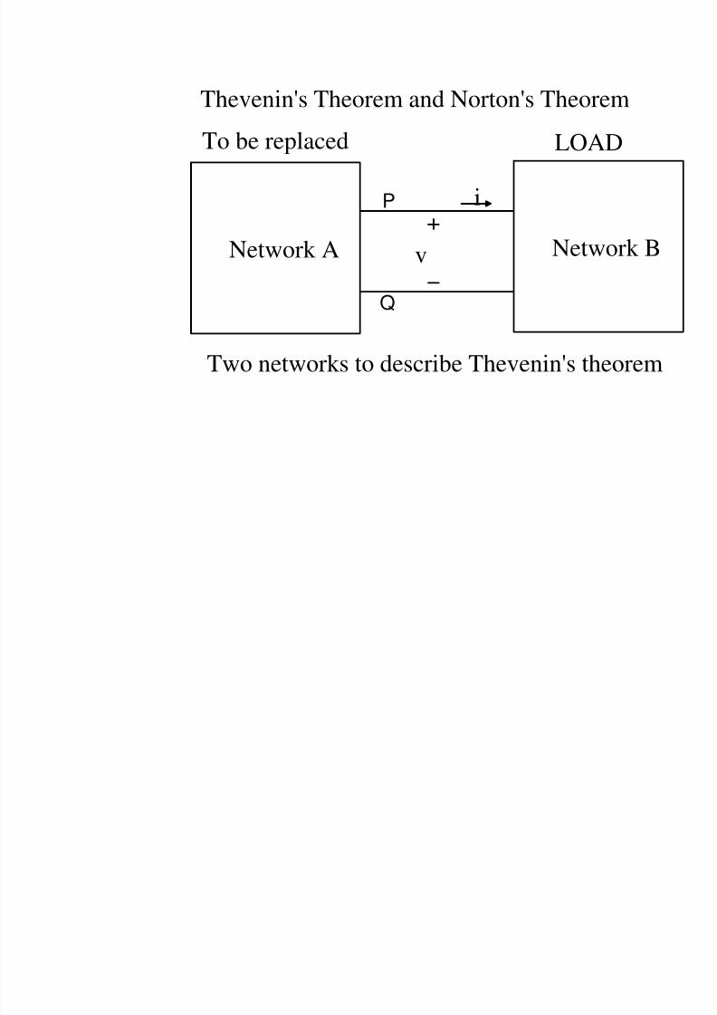
hevenin's Theorem : Characteristics of Netw
Nonlinear ElemeLinear Elements
L R C D T M
Yes No
i
i
v1 i1
Independent Sources Controlled Sou
v
v
Yes Yes
8/4/2019 Network Notes IMP
http://slidepdf.com/reader/full/network-notes-imp 4/87
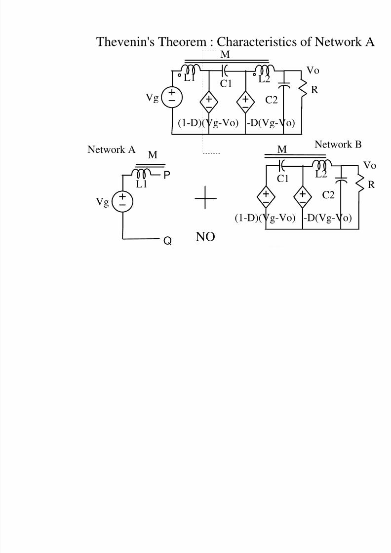
Vg
L1 L2
M
C1R
C2
Vo
(1-D)(Vg-Vo) -D(Vg-Vo)
Vg
L1
M
L2
M
C1
C2
(1-D)(Vg-Vo) -D(Vg-
Network ANetw
NO
Thevenin's Theorem : Characteristics of Net
P
Q
8/4/2019 Network Notes IMP
http://slidepdf.com/reader/full/network-notes-imp 5/87
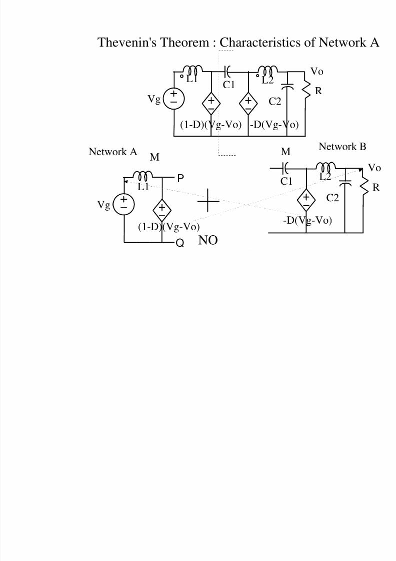
Vg
L1 L2C1R
C2
Vo
(1-D)(Vg-Vo) -D(Vg-Vo)
Vg
L1
M
L2
M
C1
C2
(1-D)(Vg-Vo)-D(Vg-Vo)
Network ANetw
NO
Thevenin's Theorem : Characteristics of Net
P
Q
8/4/2019 Network Notes IMP
http://slidepdf.com/reader/full/network-notes-imp 6/87
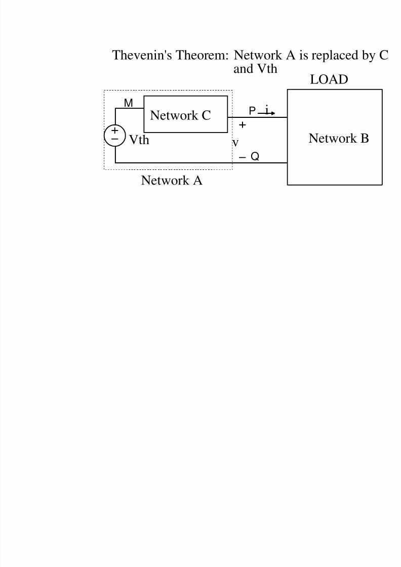
Thevenin's Theorem: Network A is replac
and Vth
Netwov
i
LOAD
Network C
Vth
Network A
P
Q
M
8/4/2019 Network Notes IMP
http://slidepdf.com/reader/full/network-notes-imp 7/87
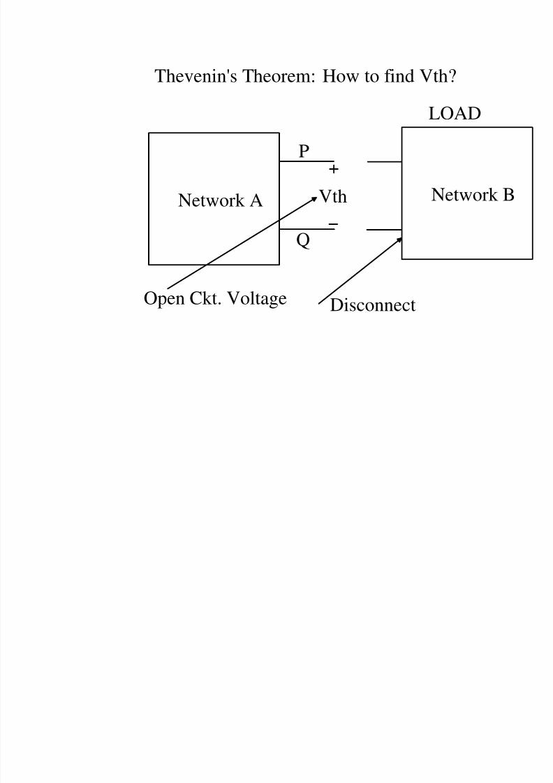
Thevenin's Theorem: How to find Vth?
Netw
LOAD
VthNetwork A
Disconnect
P
Q
Open Ckt. Voltage
8/4/2019 Network Notes IMP
http://slidepdf.com/reader/full/network-notes-imp 8/87
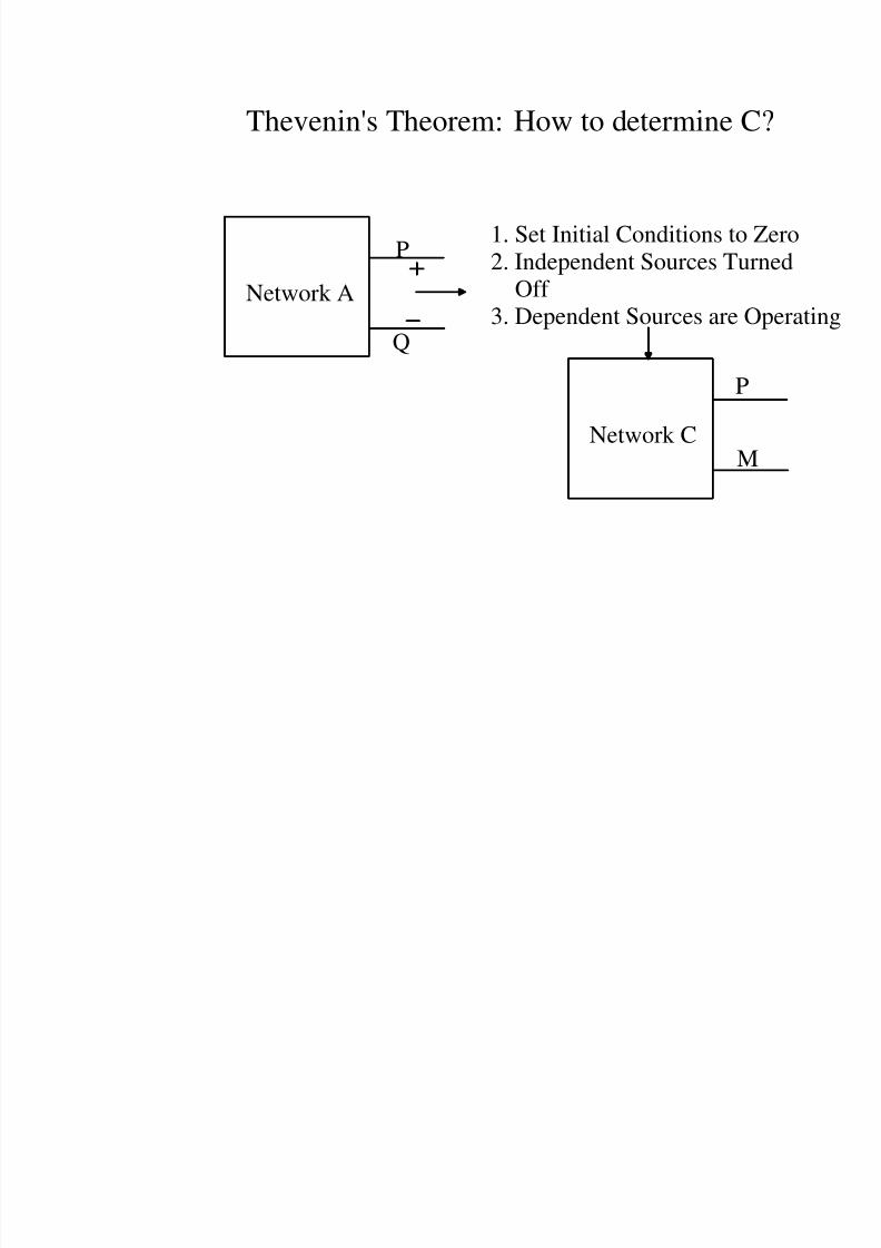
Thevenin's Theorem: How to determine C
Network A
P
Q
1. Set Initial Conditions to
2. Independent Sources TuOff
3. Dependent Sources are O
Network C
P
M
8/4/2019 Network Notes IMP
http://slidepdf.com/reader/full/network-notes-imp 9/87
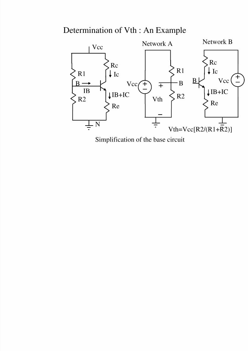
Determination of Vth : An Example
Vcc
R1
R2
Rc
Re
IB
Ic
IB+IC
Simplification of the base circuit
Vcc
R1
R2
R
R
I
N
B
B
B
Network A Net
Vth
Vth=Vcc[R2/(R

8/4/2019 Network Notes IMP
http://slidepdf.com/reader/full/network-notes-imp 10/87
hevenin's Theorem : Characteristics of Netw
Nonlinear ElemeLinear Elements
L R C D T M
Yes
i
i
v1 i1
Independent Sources Controlled Sou
v
v
Yes Yes
Yes
8/4/2019 Network Notes IMP
http://slidepdf.com/reader/full/network-notes-imp 11/87
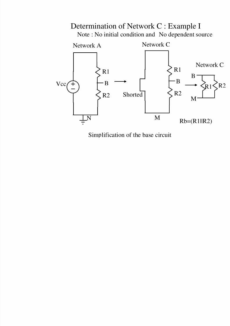
Determination of Network C : Example
Sim lification of the base circuit
Vcc
R1
R2
B
Network A
R1
R2
B
Network C
N
Shorted
B
Rb=(R
Note : No initial condition and No dependent
M
M

8/4/2019 Network Notes IMP
http://slidepdf.com/reader/full/network-notes-imp 12/87
Vcc
R1
R2
Rc
Re
IB
Ic
IB+IC
Simplification of the base circuit
R
R
I
N
B
B
Net
Vth=Vcc[R2/(R1+R2)]
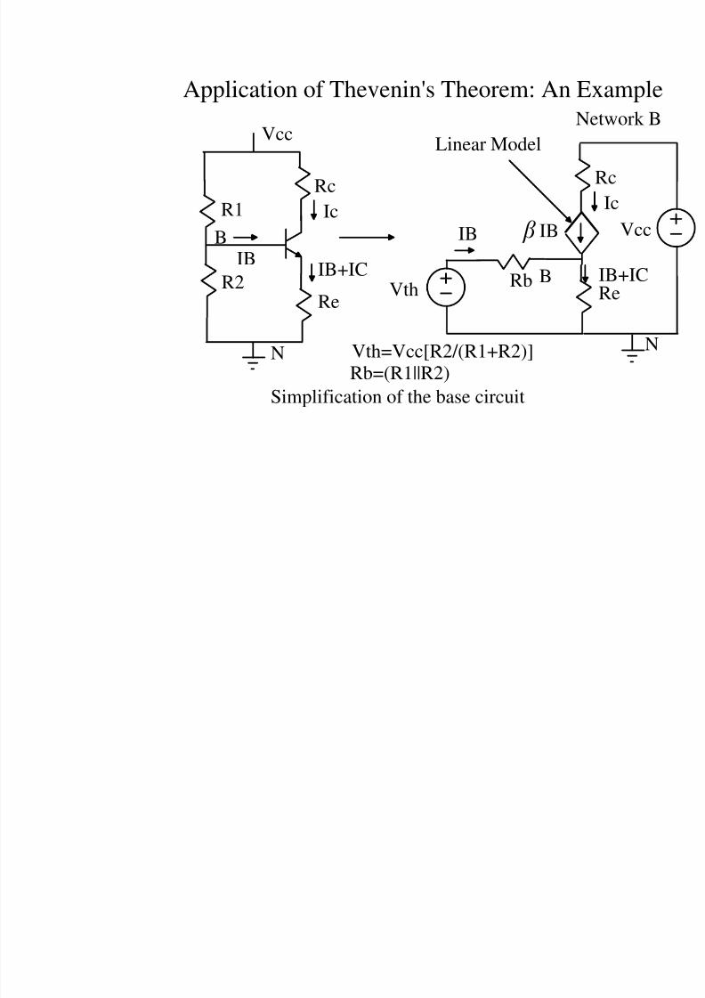
Application of Thevenin's Theorem: An Ex
Vth
Rb
Rb=(R1||R2)
M
8/4/2019 Network Notes IMP
http://slidepdf.com/reader/full/network-notes-imp 13/87
Vcc
R1
R2
Rc
Re
IB
Ic
IB+IC
Simplification of the base circuit
R
RI
N
B
B
Net
Vth=Vcc[R2/(R1+R2)]
Application of Thevenin's Theorem: An Ex
VthRb
Rb=(R1||R2)
IB IB
Linear Model
8/4/2019 Network Notes IMP
http://slidepdf.com/reader/full/network-notes-imp 14/87
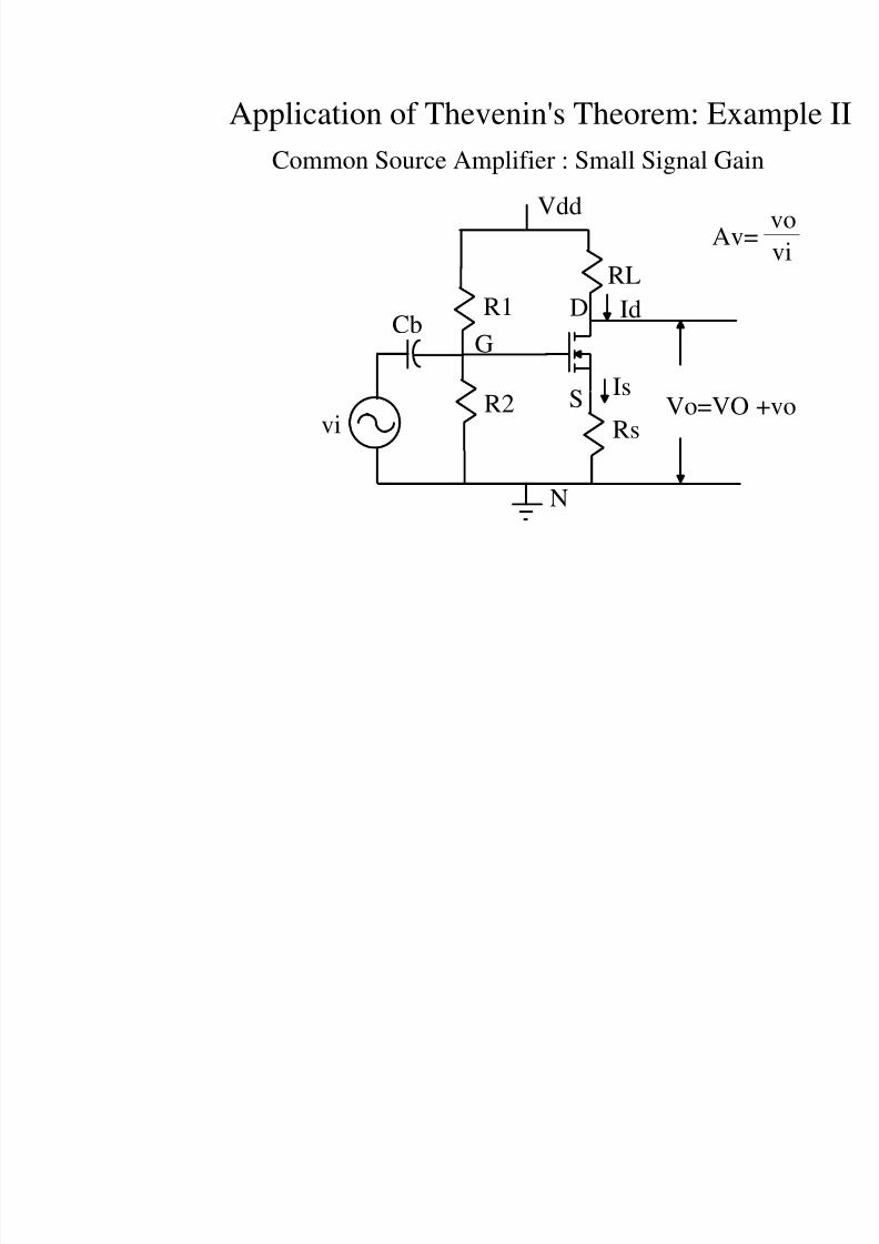
Application of Thevenin's Theorem: Exa
Common Source Amplifier : Small Signal Gai
Vdd
R1
R2
RL
Rs
Id
Is
N
GCb
Vo=VOvi
D
S
Av=
8/4/2019 Network Notes IMP
http://slidepdf.com/reader/full/network-notes-imp 15/87
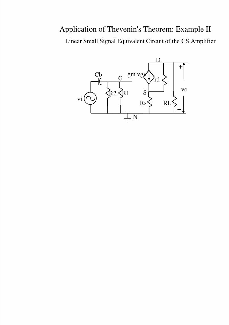
Application of Thevenin's Theorem: Examp
R1R2
rd
Rs
N
G
Cb
vo
viRL
S
D
gm vgs
Linear Small Signal Equivalent Circuit of the CS A
8/4/2019 Network Notes IMP
http://slidepdf.com/reader/full/network-notes-imp 16/87
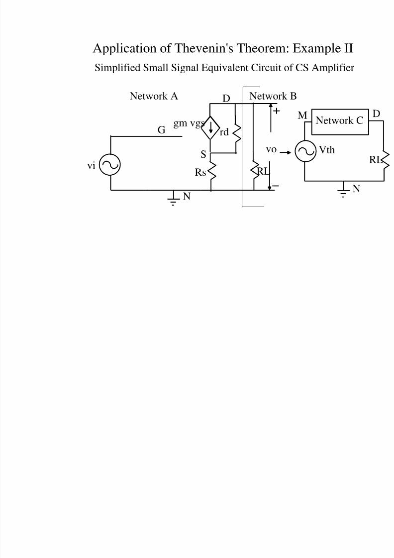
Application of Thevenin's Theorem: Exampl
Simplified Small Signal Equivalent Circuit of CS Ampl
rd
Rs
N
G
vo
viRL
S
D
gm vgs
Network BNetwork A
Netw
Vth
M
8/4/2019 Network Notes IMP
http://slidepdf.com/reader/full/network-notes-imp 17/87
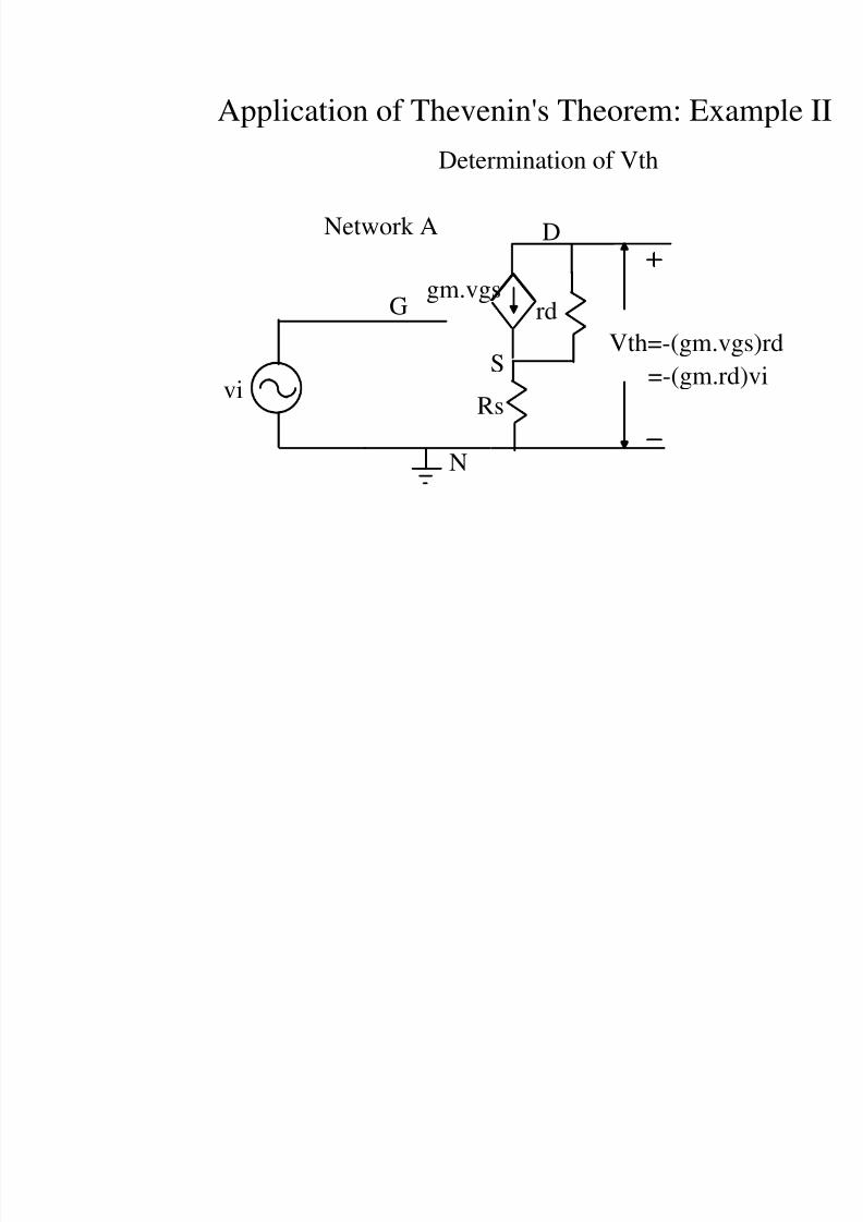
Application of Thevenin's Theorem: Exa
rd
Rs
N
G
viS
D
gm.vgs
Network A
Vth=-(gm.vg
Determination of Vth
=-(gm.rd
8/4/2019 Network Notes IMP
http://slidepdf.com/reader/full/network-notes-imp 18/87
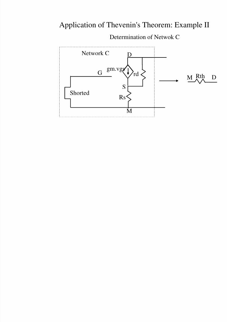
Application of Thevenin's Theorem: Examp
rd
Rs
G
S
D
gm.vgs
Network C
Determination of Netwok C
Shorted
M
M
8/4/2019 Network Notes IMP
http://slidepdf.com/reader/full/network-notes-imp 19/87
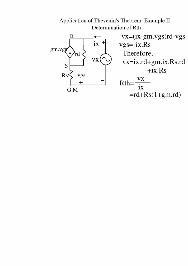
Application of Thevenin's Theorem: Examp
Determination of Rth
rd
Rs
G,M
S
D
gm.vgs
vgs
vx
ixvx=(ix-gm.vg
vgs=-ix.Rs
Therefore,
vx=ix.rd+gm+ix.R
Rth=vx
ix
=rd+Rs(1+
8/4/2019 Network Notes IMP
http://slidepdf.com/reader/full/network-notes-imp 20/87
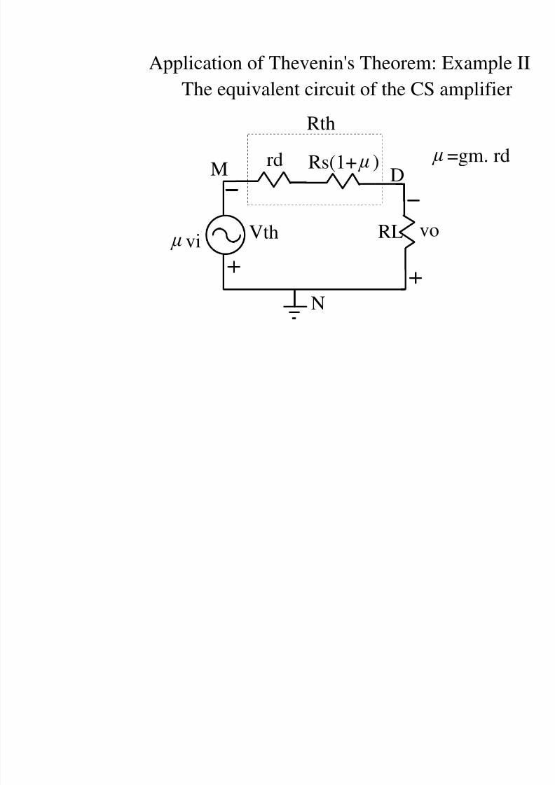
Application of Thevenin's Theorem: Exa
Vth
DM
N
The equivalent circuit of the CS amp
RL
rd Rs(1+ )
Rth
=gm
vivo
8/4/2019 Network Notes IMP
http://slidepdf.com/reader/full/network-notes-imp 21/87
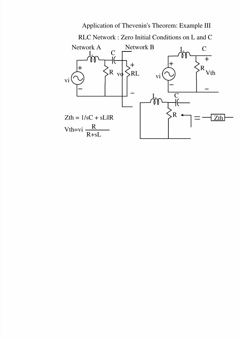
Application of Thevenin's Theorem: Example
vi
vo
L C
R RL
RLC Network : Zero Initial Conditions on L and
vi
Network A Network B L C
R
L C
RZth = 1/sC + sL||R
Vth=vi RR+sL
8/4/2019 Network Notes IMP
http://slidepdf.com/reader/full/network-notes-imp 22/87
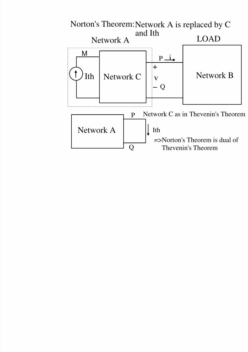
Norton's Theorem:Network A is replacedand Ith
Netwv
i
LOA
Network CIth
Network A
P
Q
M
Network A Ith
Network C as in Theveni
=>Norton's Theorem
Thevenin's Theore
P
Q
8/4/2019 Network Notes IMP
http://slidepdf.com/reader/full/network-notes-imp 23/87
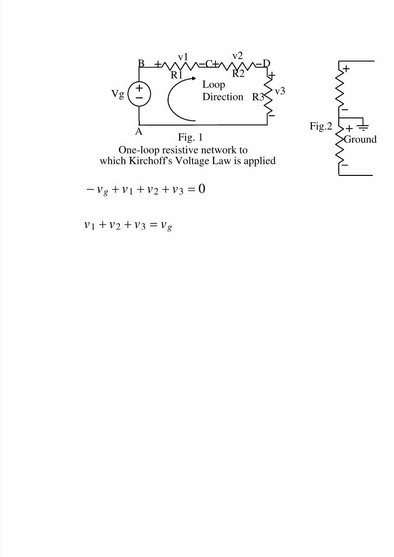
− vg + v1 + v2 + v3 = 0
v1 + v2 + v3 = vg
VgLoop
Direction
B
A
v1 v2
v3
R1 R2
R3
C D
One-loop resistive network towhich Kirchoff's Voltage Law is applied
Fig. 1
Fig.2
8/4/2019 Network Notes IMP
http://slidepdf.com/reader/full/network-notes-imp 24/87
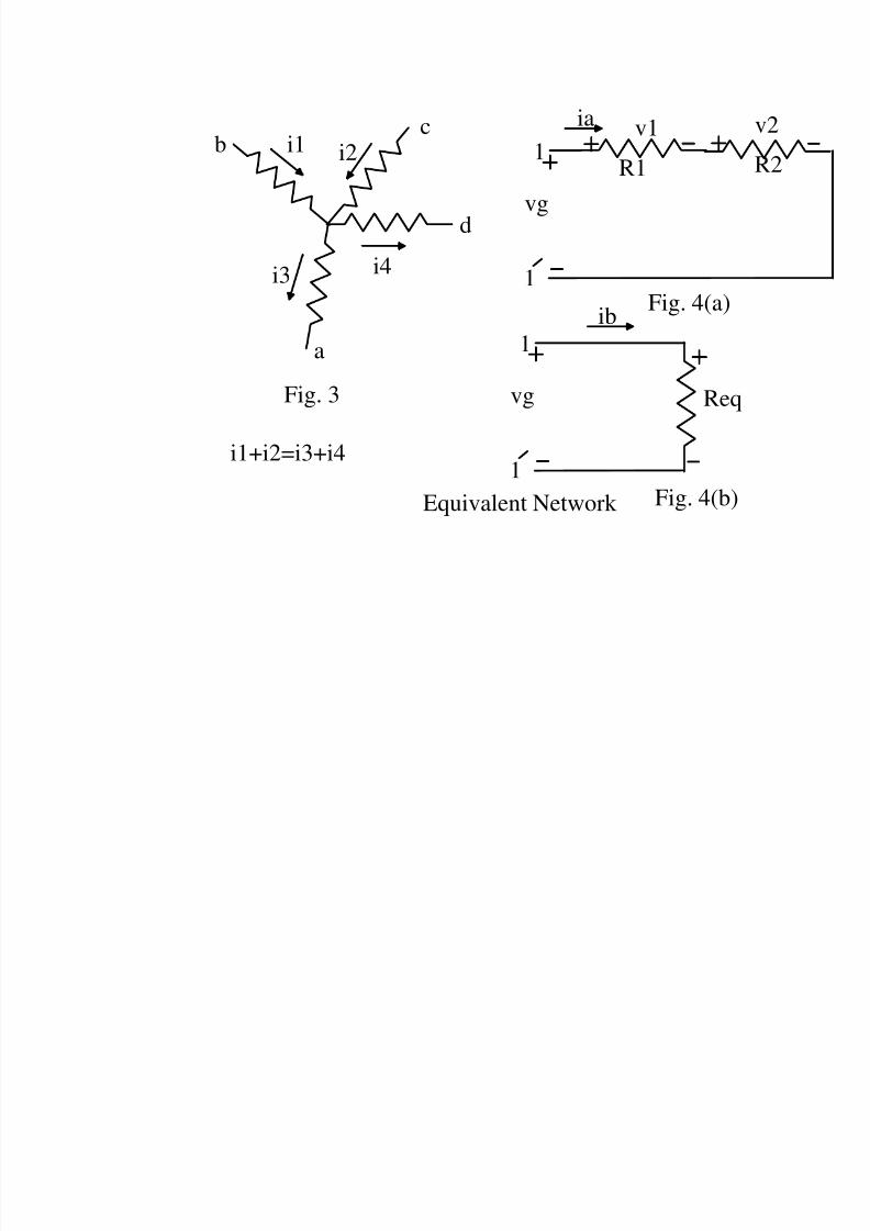
v1
R11
vg
1
1
vg
1
Req
ib
ia
i1 i2
i4i3
b
c
d
a
Fig. 3
Fig. 4(a)
Fig. 4(b)
i1+i2=i3+i4
Equivalent Network
8/4/2019 Network Notes IMP
http://slidepdf.com/reader/full/network-notes-imp 25/87
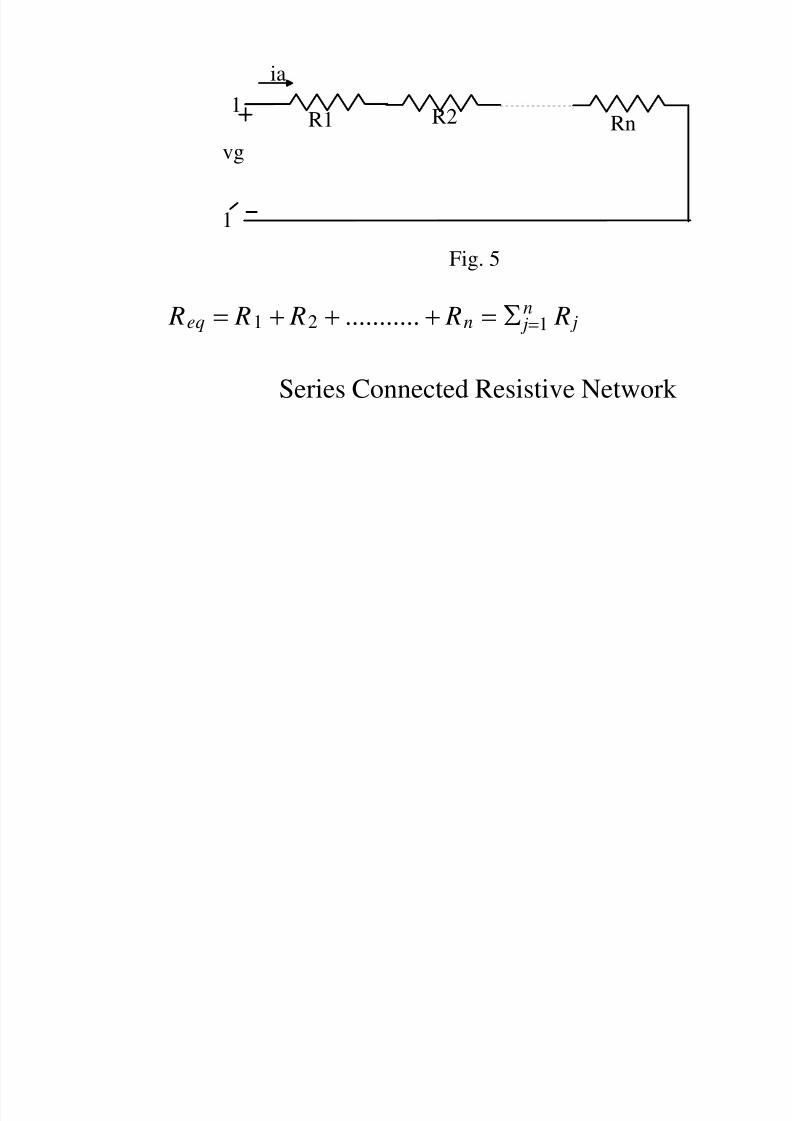
Req = R1 + R2 + ........... + Rn = j=1n R j
Series Connected Resistive Network
R1 R21
vg
1
ia
Fig. 5
Rn
8/4/2019 Network Notes IMP
http://slidepdf.com/reader/full/network-notes-imp 26/87
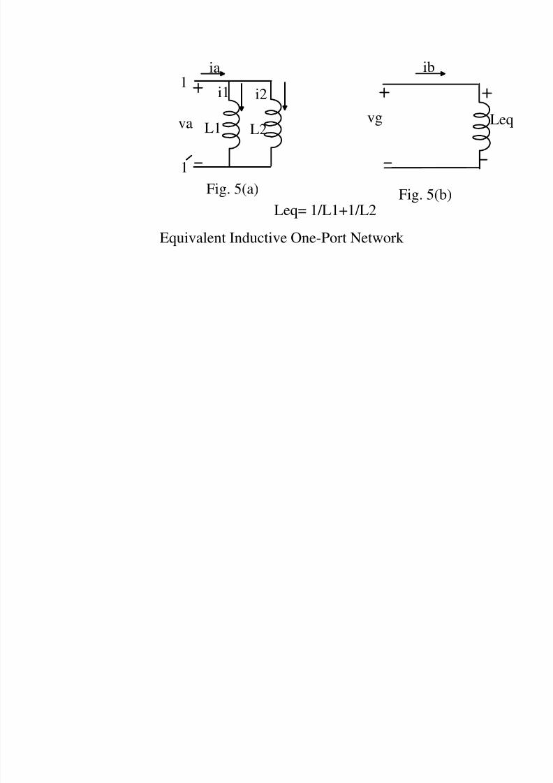
Fig. 5(a)
1
1
ia
L1 L2va
i1 i2
Fig. 5(b)
vg
ib
Equivalent Inductive One-Port Network
Leq= 1/L1+1/L2
8/4/2019 Network Notes IMP
http://slidepdf.com/reader/full/network-notes-imp 27/87
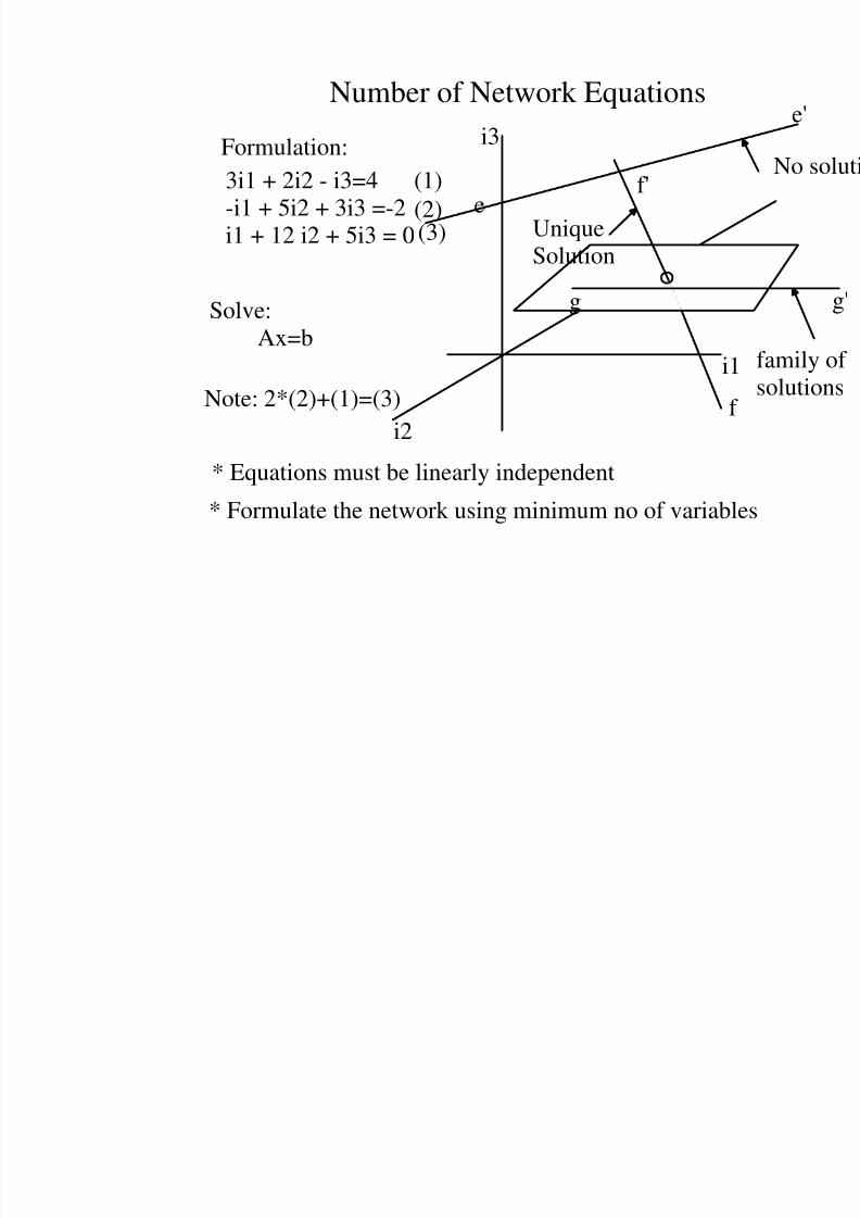
Number of Network Equations
i1
i3
i2
ef'
f
3i1 + 2i2 - i3=4-i1 + 5i2 + 3i3 =-2i1 + 12 i2 + 5i3 = 0
* Equations must be linearly independent
Ax=b
UniqueSolution
gSolve:
* Formulate the network using minimum no of variabl
Formulation:(1)
(2)(3)
Note: 2*(2)+(1)=(3)
8/4/2019 Network Notes IMP
http://slidepdf.com/reader/full/network-notes-imp 28/87
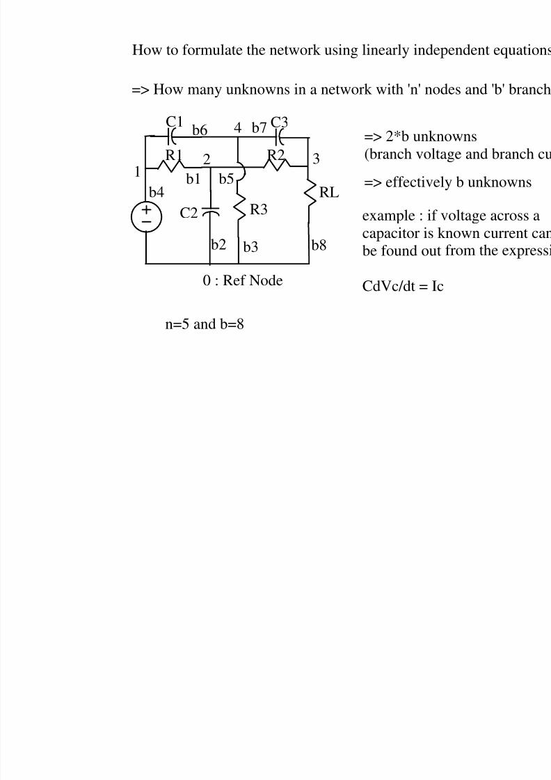
How to formulate the network using linearly independ
=> How many unknowns in a network with 'n' nodes a
=> 2*b unknown(branch voltage a
=> effectively b u
example : if voltacapacitor is knowbe found out
CdVc/dt = Ic
from
n=5 and b=8
0 : Ref Node
12
4
3
C1 C3
R1
C2 R3RL
b1
b2 b3
b4
b5
b6 b7
R2
b8
8/4/2019 Network Notes IMP
http://slidepdf.com/reader/full/network-notes-imp 29/87
1
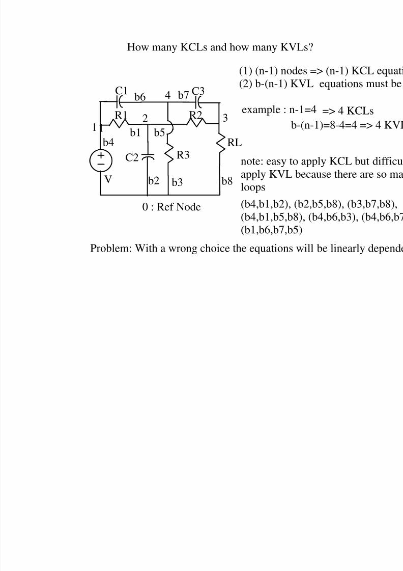
How many KCLs and how many KVLs?
(1) (n-1) nodes => (n-1(2) b-(n-1) KVL equat
example : n-1=4 => 4
b-(n-1)=8-4
0 : Ref Node
12
4
3
C1 C3
R1
C2 R3RL
b1
b2 b3
b4b5
b6 b7
R2
b8
note: easy to apply KC
apply KVL because thloops
V
(b4,b1,b2), (b2,b5,b8),(b4,b1,b5,b8), (b4,b6,b(b1,b6,b7,b5)
Problem: With a wrong choice the equations will be line
8/4/2019 Network Notes IMP
http://slidepdf.com/reader/full/network-notes-imp 30/87
1
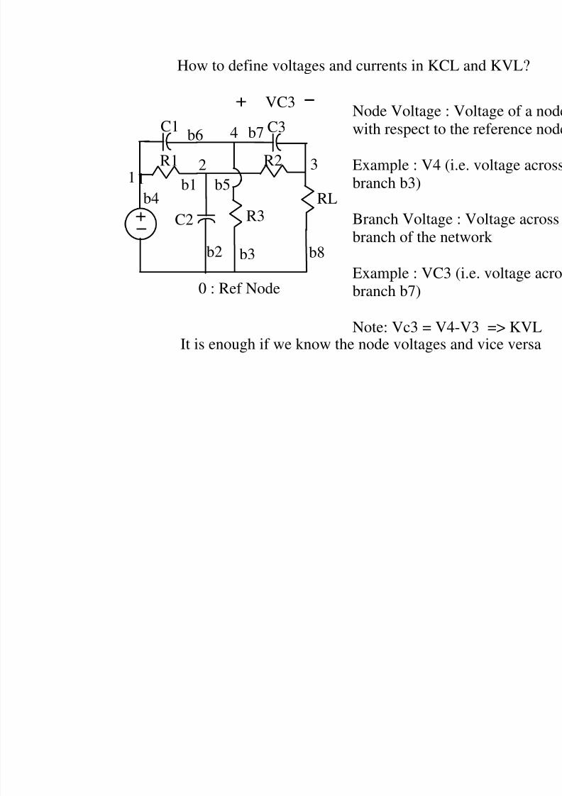
How to define voltages and currents in KCL an
0 : Ref Node
12
4
3
C1 C3
R1
C2 R3RL
b1
b2 b3
b4b5
b6 b7
R2
b8
Node Voltage : Voltwith respect to the r
Example : V4 (i.e. vbranch b3)
Branch Voltage : Vobranch of the netwo
Example : VC3 (i.e.
branch b7)
Note: Vc3 = V4-V3It is enough if we know the node voltages and v
VC3
8/4/2019 Network Notes IMP
http://slidepdf.com/reader/full/network-notes-imp 31/87
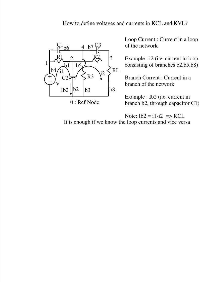
How to define voltages and currents in KCL an
0 : Ref Node
12
4
3
C1 C3
R1
C2 R3RL
b1
b2 b3
b4b5
b6 b7
R2
b8
Loop Current : Currof the network
Example : i2 (i.e. cuconsisting of branch
Branch Current : Cubranch of the netwo
Example : Ib2 (i.e. c
branch b2, through c
Note: Ib2 = i1-i2 =>It is enough if we know the loop currents and v
i2
VIb2
i1
8/4/2019 Network Notes IMP
http://slidepdf.com/reader/full/network-notes-imp 32/87
RL
0 : Ref Node
12
4
3
C1 C3
R1
C2 R3
b1
b2 b3
b4b5
b6 b7R2
b8V
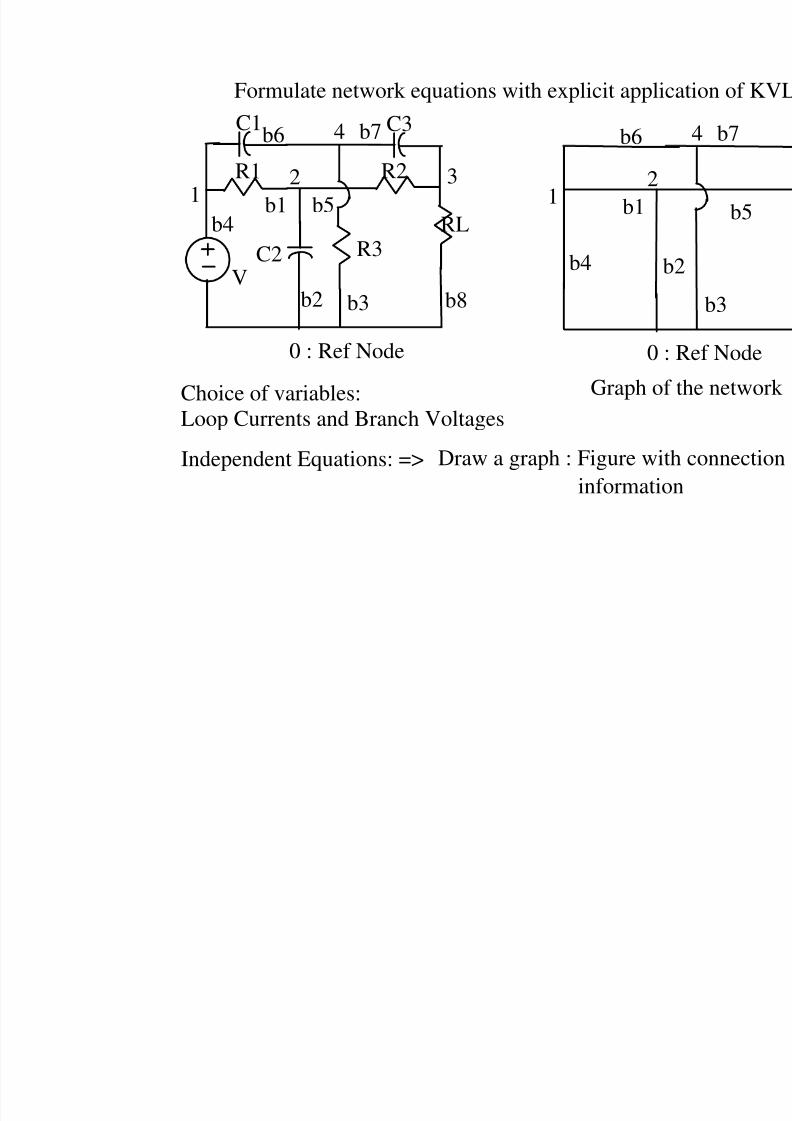
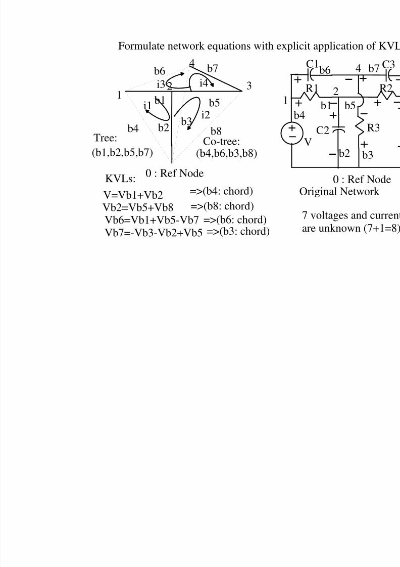
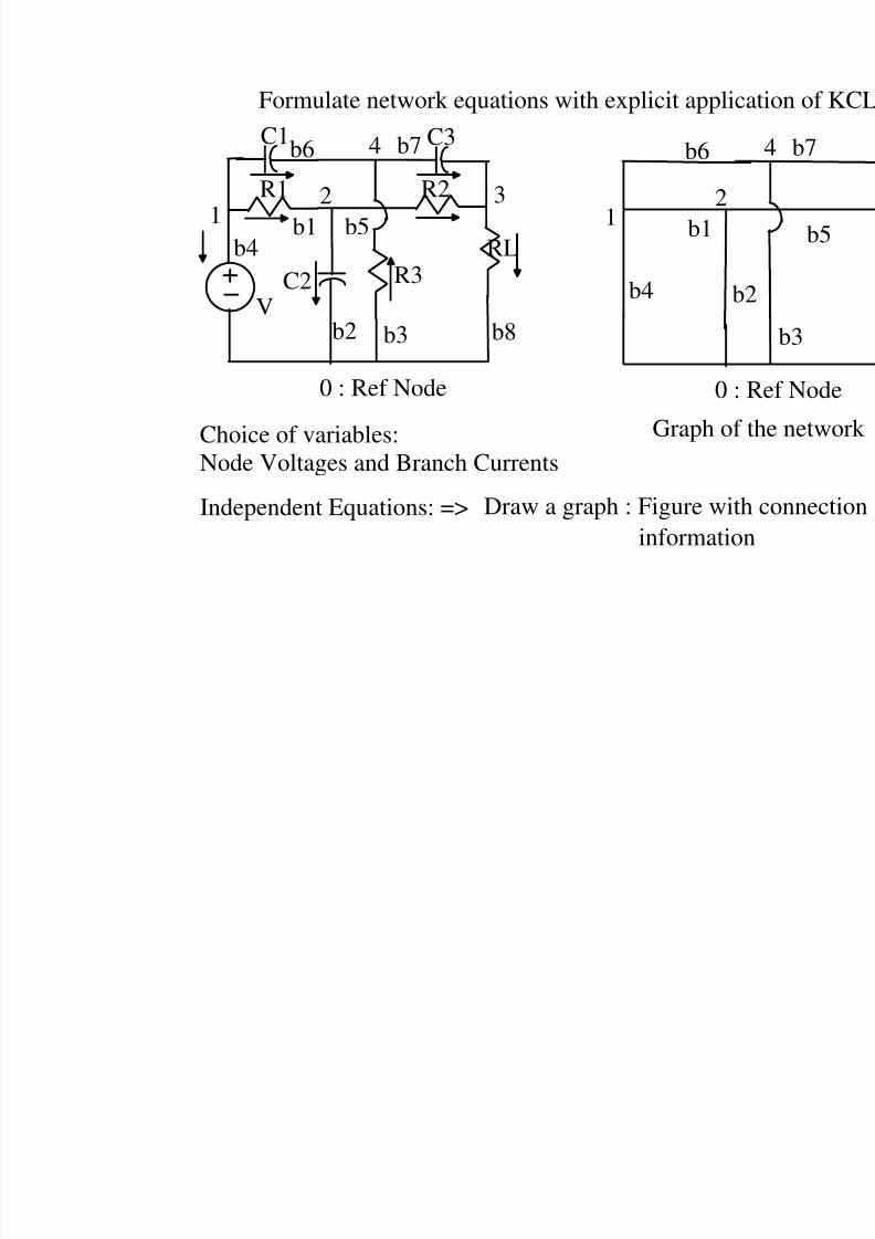
Formulate network equations with explicit applic
Independent Equations: => Draw a graph : Figure with
information
0 :
12
b1
bb4
b6
Choice of variables:
Loop Currents and Branch Voltages
Graph of

8/4/2019 Network Notes IMP
http://slidepdf.com/reader/full/network-notes-imp 33/87
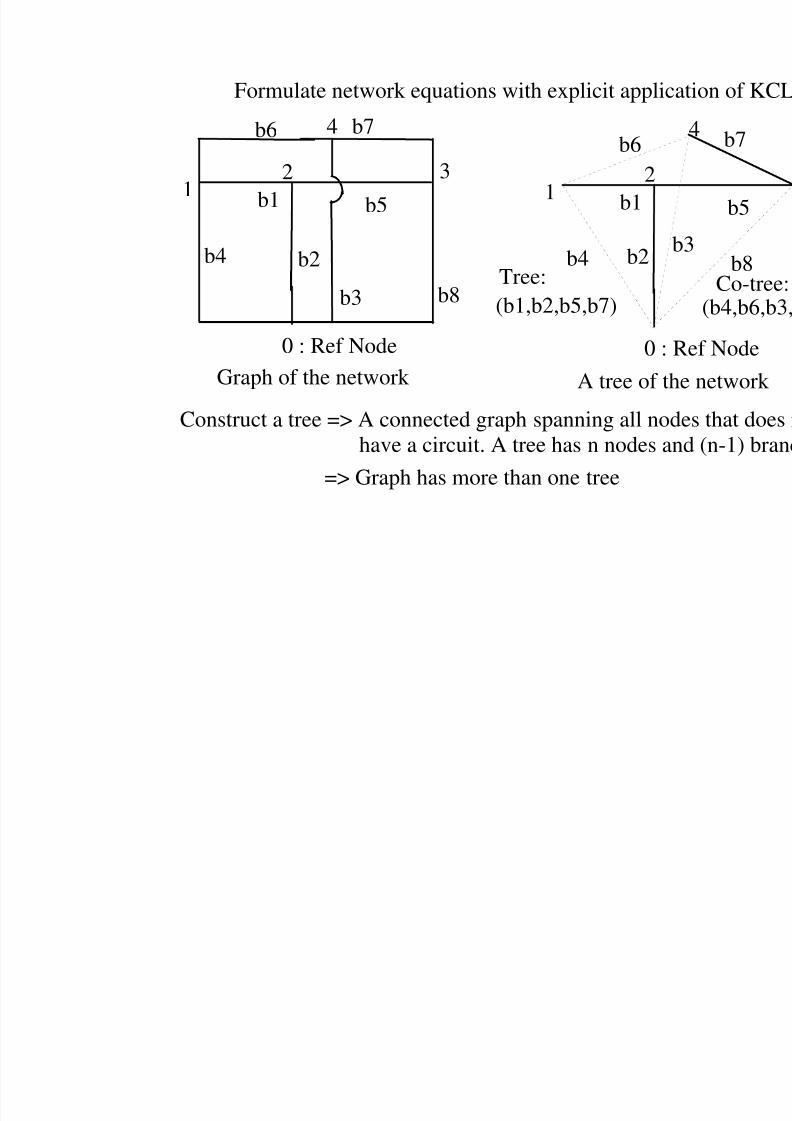
Formulate network equations with explicit applic
0 : Ref Node
12
43
b1
b2
b3
b4
b5
b6 b7
b8
Graph of the network
0 : R
Construct a tree => A connected graph spanning all nodhave a circuit. A tree has n nodes an
A tree of th
=> Graph has more than one tree
12
b1
b2b
b4
b6
(b1,b2,b5,b7)Tree:
8/4/2019 Network Notes IMP
http://slidepdf.com/reader/full/network-notes-imp 34/87
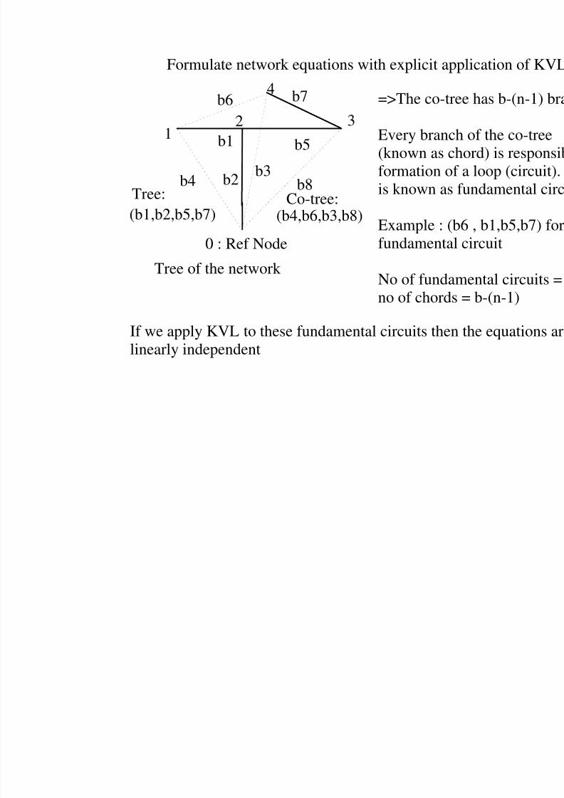
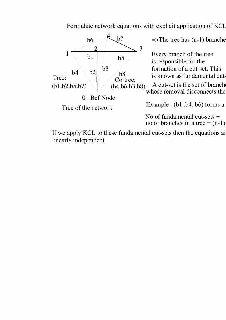
Formulate network equations with explicit applic
Tree of the network
0 : Ref Node
12
4
3
b1
b2b3
b4
b5
b6 b7
b8
(b1,b2,b5,b7)Tree: Co-tree:
(b4,b6,b3,b8)
=>The co-tree h
Every branch of(known as chordformation of a lo
is known as fund
Example : (b6 , fundamental circ
No of fundamen
no of chords = b
If we apply KVL to these fundamental circuits then thelinearly independent
8/4/2019 Network Notes IMP
http://slidepdf.com/reader/full/network-notes-imp 35/87
Formulate network equations with explicit applic
0 : Ref Node0
12
C1
R1
C2
b1
b
b4
b6
V
Original N
12
4
3
b1
b2b3
b4
b5
b6 b7
b8
(b1,b2,b5,b7)Tree: Co-tree:
(b4,b6,b3,b8)
V=Vb1+Vb2
Vb2=Vb5+Vb8Vb6=Vb1+Vb5-Vb7Vb7=-Vb3-Vb2+Vb5
=>(b4: chord)
=>(b8: chord)=>(b6: chord)=>(b3: chord)
KVLs:
i1i2
i3 i4
7 voltage
are unkn
8/4/2019 Network Notes IMP
http://slidepdf.com/reader/full/network-notes-imp 36/87
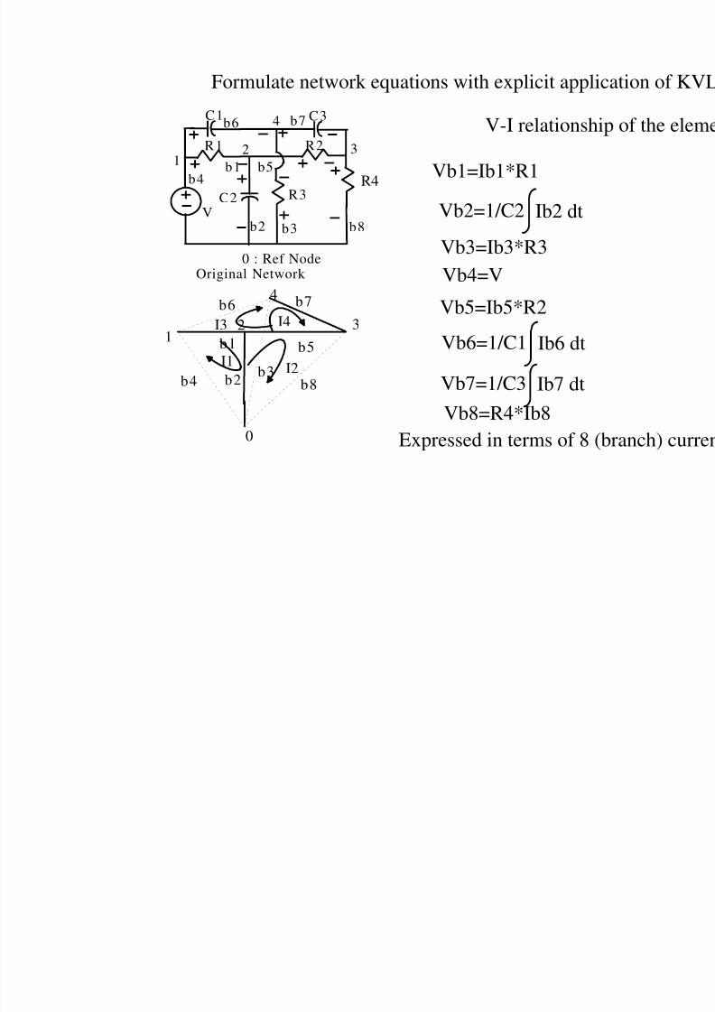
Formulate network equations with explicit applic
0 : Ref Node
12
4
3
C1 C3
R1
C2 R3
b1
b2 b3
b4b5
b6 b7R2
b8V
Original Network
V-I relationship
12
4
3
b1
b2 b3b4
b5
b6 b7
b8
0
I1
I3
I2
I4
Vb1=Ib1*R1
Vb2=1/C2 Ib2 dt
Vb3=Ib3*R3Vb4=V
Vb5=Ib5*R2
Vb6=1/C1 Ib6 dt
Vb7=1/C3 Ib7 dt
Vb8=R4*Ib8
R4
Expressed in terms of 8 (b
8/4/2019 Network Notes IMP
http://slidepdf.com/reader/full/network-notes-imp 37/87
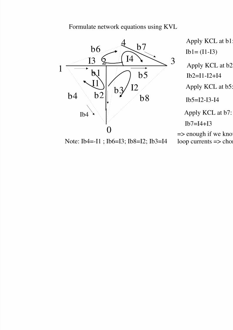
Formulate network equations using KVL
Appl
Ib1=
12
4
3
b1
b2b3
b4
b5
b6 b7
b8
0
I1
I3
I2
I4Appl
Ib2=
Appl
Ib5=
Apply
Ib7=I
Note: Ib4=-I1 ; Ib6=I3; Ib8=I2; Ib3=I4
Ib4
=> enouloop cur
8/4/2019 Network Notes IMP
http://slidepdf.com/reader/full/network-notes-imp 38/87
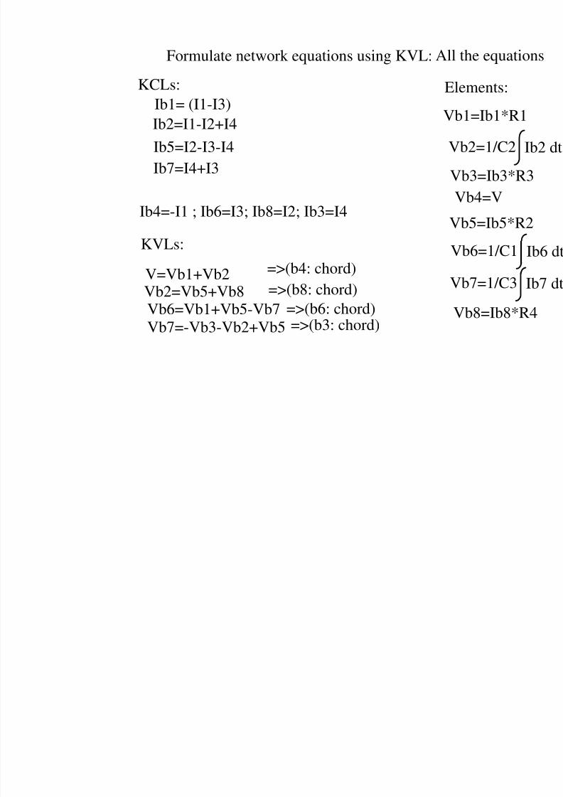
Formulate network equations using KVL:
Ib1= (I1-I3)
Ib2=I1-I2+I4
Ib5=I2-I3-I4
Ib7=I4+I3
Ib4=-I1 ; Ib6=I3; Ib8=I2; Ib3=I4
V=Vb1+Vb2
Vb2=Vb5+Vb8Vb6=Vb1+Vb5-Vb7Vb7=-Vb3-Vb2+Vb5
=>(b4: chord)
=>(b8: chord)=>(b6: chord)=>(b3: chord)
Vb1=
Vb2=
Vb3=
Vb4
Vb5=
Vb6=
Vb7=
All the
Vb8
KVLs:
KCLs: Eleme
8/4/2019 Network Notes IMP
http://slidepdf.com/reader/full/network-notes-imp 39/87
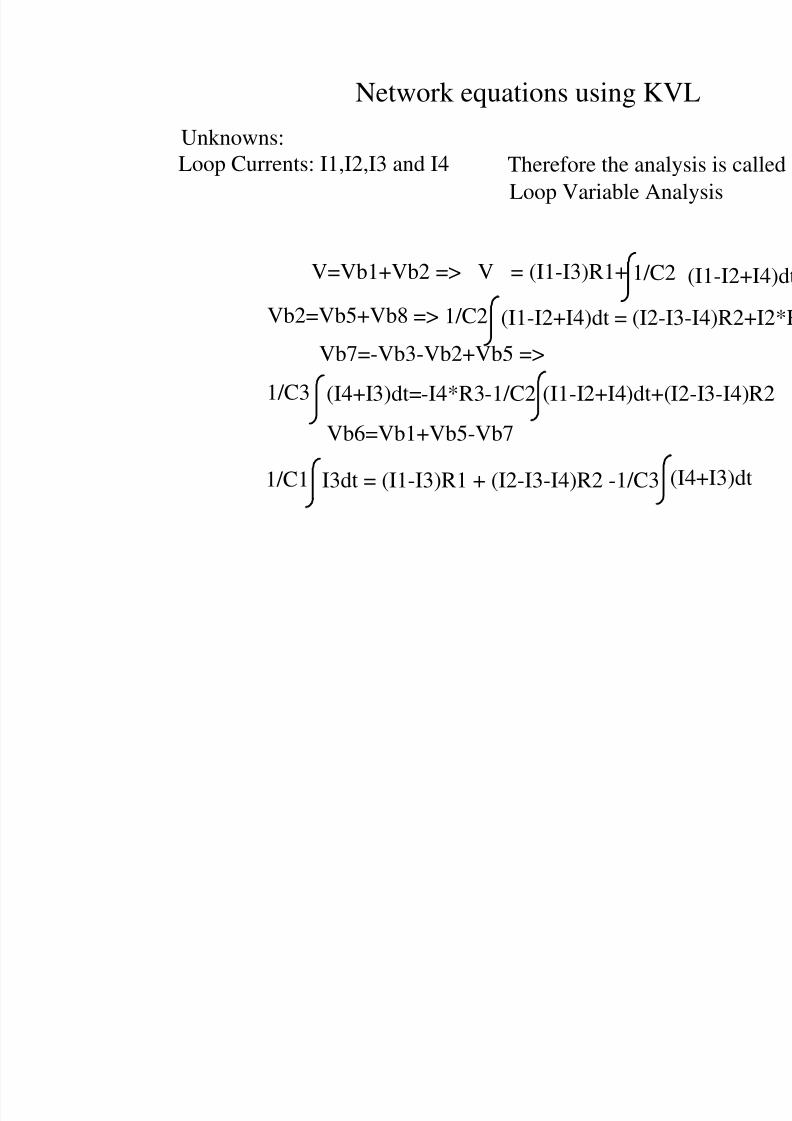
Network equations using KV
Vb6=Vb1+Vb5-Vb7
Vb7=-Vb3-Vb2+Vb5 =>
V=Vb1+Vb2 => V = (I1-I3)R1+ 1/C2
Vb2=Vb5+Vb8 => 1/C2 (I1-I2+I4)dt = (I2-I
1/C3 (I4+I3)dt=-I4*R3-1/C2 (I1-I2+I4)dt+(I
I3dt = (I1-I3)R1 + (I2-I3-I4)R2 -1/C3 (1/C1
Unknowns:Loop Currents: I1,I2,I3 and I4
Loop Variable Ana
Therefore the analy
8/4/2019 Network Notes IMP
http://slidepdf.com/reader/full/network-notes-imp 40/87
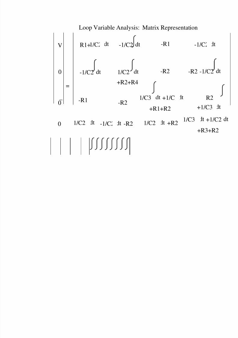
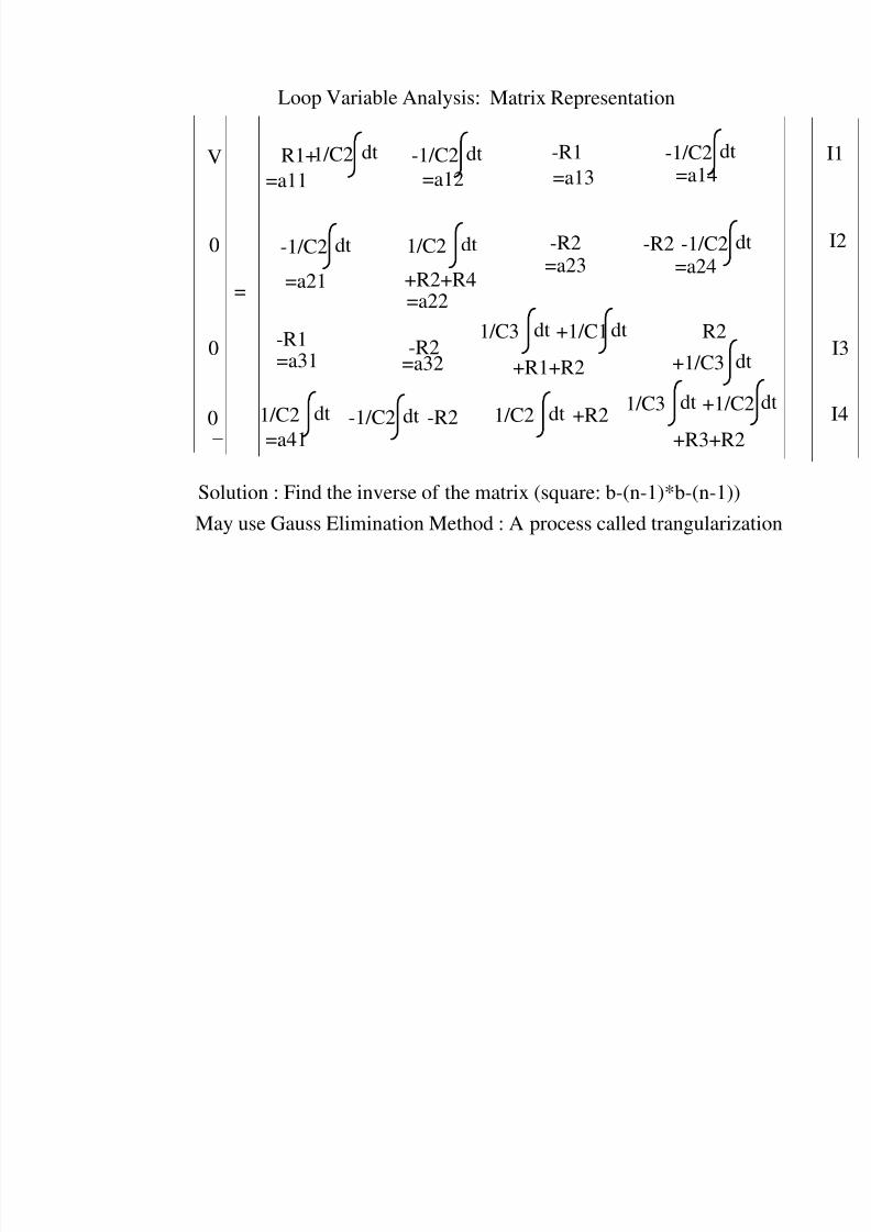
Loop Variable Analysis: Matrix Representation
-1/C2 dt -R1
-1/C2 dt 1/C2 dt
+R2+R4
-1-R2 -R2
-R1 -R21/C3 dt +1/C1dt
+R1+R2 +1
1/C2 dt -1/C2 dt -R2 1/C2 dt +R2
1/C3 dt
+R
0
0
0
1/C2 dtR1+V
=
-1/C
8/4/2019 Network Notes IMP
http://slidepdf.com/reader/full/network-notes-imp 41/87
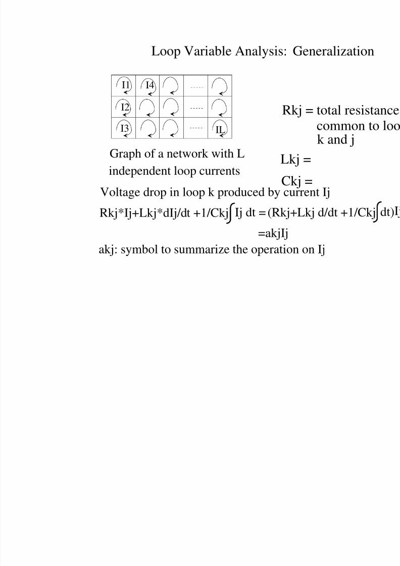
Loop Variable Analysis: Generali
Graph of a network with L
independent loop currents
I1
I2
I3
I4
IL
Voltage drop in loop k produced by current Ij
Rkj*Ij+Lkj*dIj/dt +1/Ckj Ij dt = (Rkj+Lkj d/dt
=akjIj
akj: symbol to summarize the operation on Ij
Rkj = totalcom
k anLkj =
Ckj =
8/4/2019 Network Notes IMP
http://slidepdf.com/reader/full/network-notes-imp 42/87
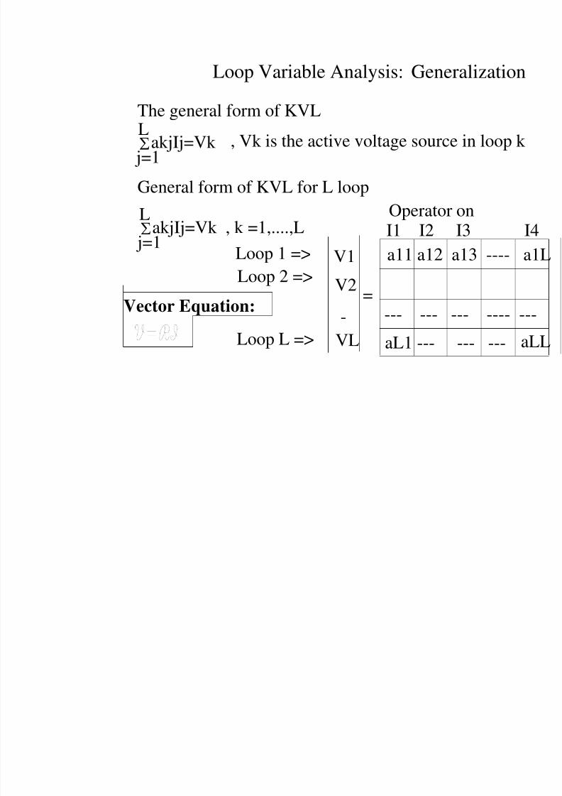
Loop Variable Analysis: Generali
The general form of KVL
akjIj=Vk j=1
L
General form of KVL for L loop
akjIj=Vk , k =1,....,L j=1
L
a11 a12 a13
aL1 --- ---
--- --- ---
Operator onI1 I2 I3
V1
V2
VL
, Vk is the active voltage source in
Loop 1 =>
Loop 2 =>
Loop L =>
-=Vector Equation:
8/4/2019 Network Notes IMP
http://slidepdf.com/reader/full/network-notes-imp 43/87
Loop Variable Analysis: Matrix Representation
-1/C2 dt -R1
-1/C2 dt 1/C2 dt
+R2+R4
-1/C2 d-R2 -R2
-R1 -R21/C3 dt +1/C1 dt
+R1+R2
R2
+1/C3 d
1/C2 dt -1/C2 dt -R2 1/C2 dt +R21/C3 dt +1/C
+R3+R2
0
0
0
1/C2 dtR1+V
=
=a11 =a12 =a13 =a14
=a21
-1/C2 dt
Solution : Find the inverse of the matrix (square: b-(n-1)*b-(n-1))
May use Gauss Elimination Method : A process called trangulariz
=a31
=a41
=a22
=a23 =a24
=a32
8/4/2019 Network Notes IMP
http://slidepdf.com/reader/full/network-notes-imp 44/87
RL
0 : Ref Node
12
4
3
C1 C3
R1
C2 R3
b1
b2 b3
b4b5
b6 b7R2
b8V
Formulate network equations with explicit applic
Independent Equations: => Draw a graph : Figure with
information
0 :
12
b1
bb4
b6
Choice of variables:
Node Voltages and Branch Currents
Graph of
8/4/2019 Network Notes IMP
http://slidepdf.com/reader/full/network-notes-imp 45/87
Formulate network equations with explicit applic
0 : Ref Node
12
43
b1
b2
b3
b4
b5
b6 b7
b8
Graph of the network
0 : R
Construct a tree => A connected graph spanning all nodhave a circuit. A tree has n nodes an
A tree of th
=> Graph has more than one tree
12
b1
b2b
b4
b6
(b1,b2,b5,b7)Tree:
8/4/2019 Network Notes IMP
http://slidepdf.com/reader/full/network-notes-imp 46/87
Formulate network equations with explicit applic
Tree of the network
0 : Ref Node
12
4
3
b1
b2b3
b4
b5
b6 b7
b8
(b1,b2,b5,b7)Tree: Co-tree:
(b4,b6,b3,b8)
=>The tree has (
Every branch ofis responsible foformation of a c
is known as fund
Example : (b1 ,b4,
No of fundamentalno of branches in a
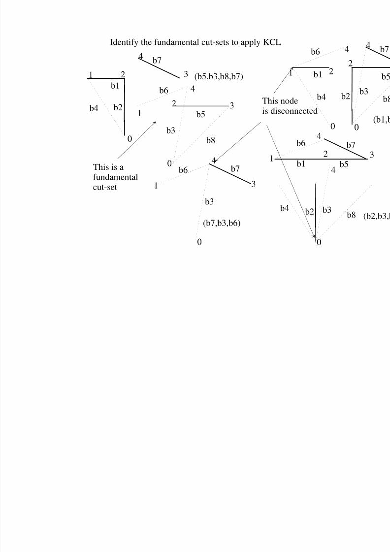
If we apply KCL to these fundamental cut-sets then thelinearly independent
A cut-set is the whose removal dis
8/4/2019 Network Notes IMP
http://slidepdf.com/reader/full/network-notes-imp 47/87
Identify the fundamental cut-sets to apply KCL
2
4
3
b1
b2b4
b7
1
1 b1
b4
b6
2
0
4
b12
b6
b2 b3b4
0
4
b3
b5
b8
b6
(b5,b3,b8,b7)
b7
3
4b6
1
b3
0
(b7,b3,b6)
0
0
1
1
4
2 3This nodeis disconnected
This is afundamentalcut-set
8/4/2019 Network Notes IMP
http://slidepdf.com/reader/full/network-notes-imp 48/87
RL
0 : Ref Node
12
4
3
C1 C3
R1
C2 R3
b1
b2 b3
b4b5
b6 b7R2
b8V
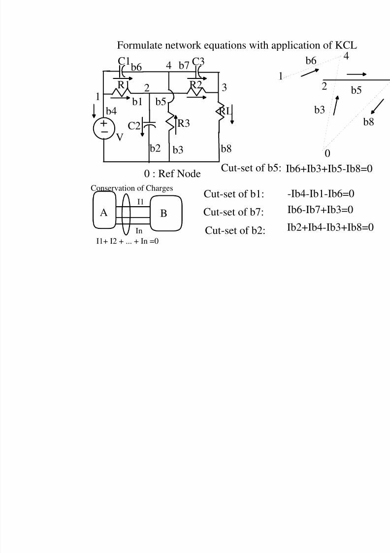
Formulate network equations with application of
b3
b6
21
0
Ib6+Ib3+Ib
-Ib4-Ib1-Ib
Ib6-Ib7+Ib
Ib2+Ib4-Ib
Cut-set of b1:
Cut-set of b7:
Cut-set of b2:
Cut-set of b5:
A BI1
In
I1+ I2 + ... + In =0
Conservation of Charges
8/4/2019 Network Notes IMP
http://slidepdf.com/reader/full/network-notes-imp 49/87
0 : Ref Node
12
4
3
C1 C3
R1
C2 R3
b1
b2 b3
b4b5
b6 b7R2
b8V
Original Network
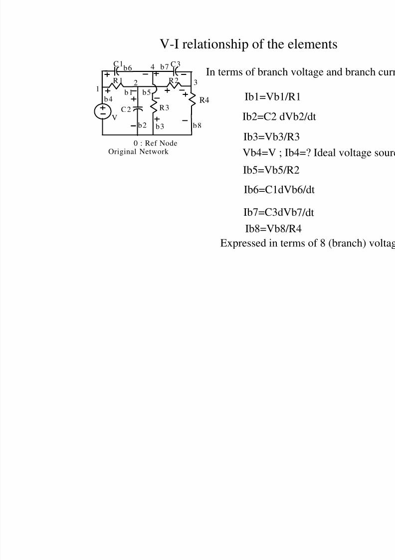
V-I relationship of the elements
Ib1=Vb1/R1
Ib2=C2 dVb2/dt
Ib3=Vb3/R3Vb4=V ; Ib4=? Ideal
Ib5=Vb5/R2
Ib6=C1dVb6/dt
Ib7=C3dVb7/dt
Ib8=Vb8/R4
R4
Expressed in terms of 8 (b
In terms of branch voltage an

8/4/2019 Network Notes IMP
http://slidepdf.com/reader/full/network-notes-imp 50/87
Formulate network equations using KC
Apply KV
Vb1=
12
4
3
b1
b2b3
b4
b5
b6 b7
b8
0
Vb2=
Vb5
Vb7
=> enounode vo
Ib8
Vb3
Vb4
Vb6
Vb
Ib5
Ib4
Ib1
Ib6 Ib7
Ib3
8/4/2019 Network Notes IMP
http://slidepdf.com/reader/full/network-notes-imp 51/87
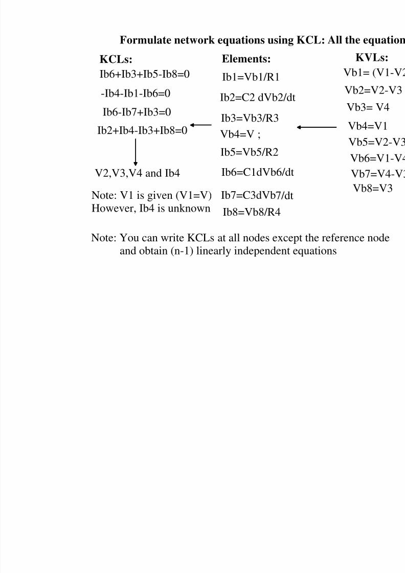
Formulate network equations using KCL: All
Elements:KCLs:
Ib6+Ib3+Ib5-Ib8=0
-Ib4-Ib1-Ib6=0
Ib6-Ib7+Ib3=0
Ib2+Ib4-Ib3+Ib8=0
V
V
Ib1=Vb1/R1
Ib2=C2 dVb2/dt
Ib3=Vb3/R3
Vb4=V ;
Ib5=Vb5/R2
Ib6=C1dVb6/dt
Ib7=C3dVb7/dt
Ib8=Vb8/R4
V2,V3,V4 and Ib4
Note: V1 is given (V1=V)
However, Ib4 is unknown
Note: You can write KCLs at all nodes except the refereand obtain (n-1) linearly independent equations
8/4/2019 Network Notes IMP
http://slidepdf.com/reader/full/network-notes-imp 52/87
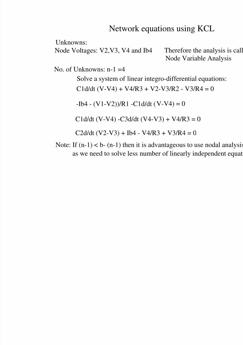
Network equations using KC
Unknowns:Node Voltages: V2,V3, V4 and Ib4
Node Variable
Therefore the an
No. of Unknowns: n-1 =4
C1d/dt (V-V4) + V4/R3 + V2-V3/R2 - V3/R4 =
-Ib4 - (V1-V2))/R1 -C1d/dt (V-V4) = 0
C1d/dt (V-V4) -C3d/dt (V4-V3) + V4/R3 = 0
C2d/dt (V2-V3) + Ib4 - V4/R3 + V3/R4 = 0
Solve a system of linear integro-differential equ
Note: If (n-1) < b- (n-1) then it is advantageous to use n
as we need to solve less number of linearly indep
8/4/2019 Network Notes IMP
http://slidepdf.com/reader/full/network-notes-imp 53/87
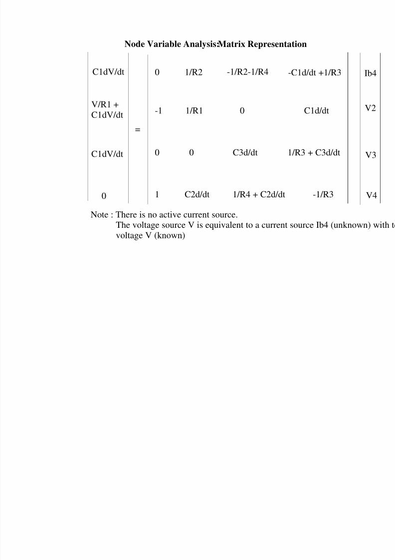
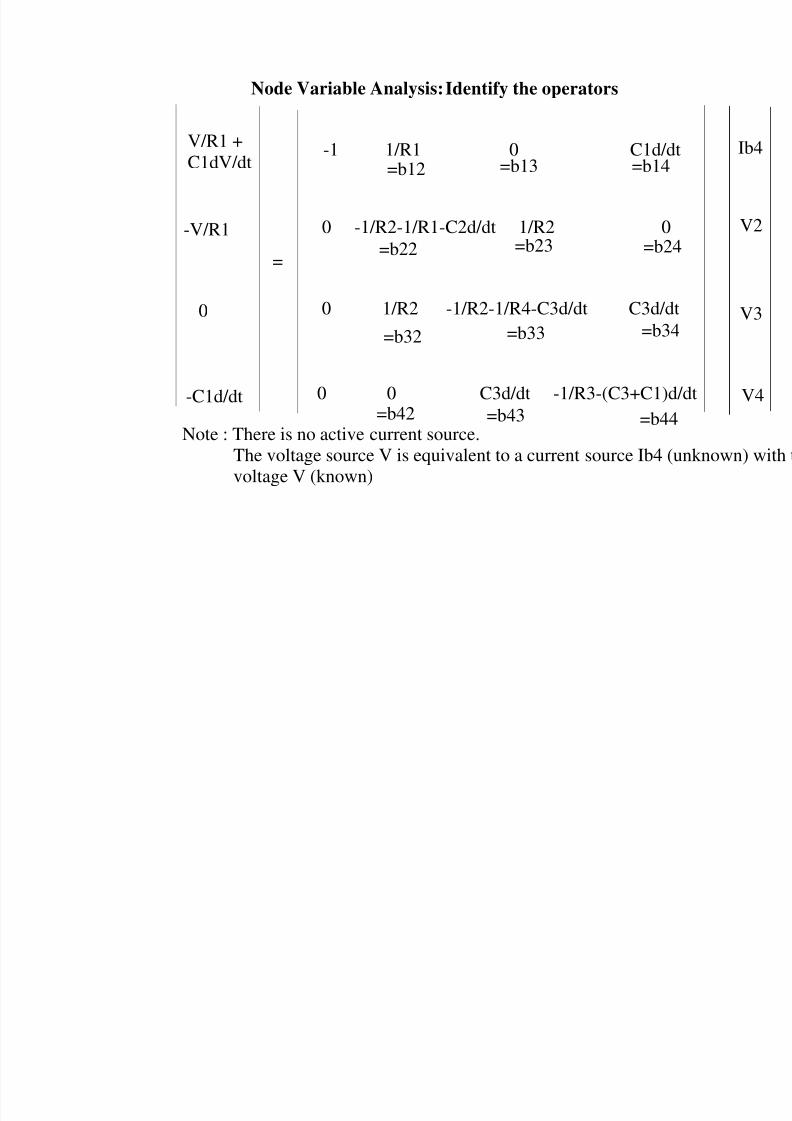
Node Variable Analysis:Matrix Representation
=
C1dV/dt 0 1/R2 -1/R2-1/R4 -C1d/dt +1/R
-1 1/R1 0 C1d/dtV/R1 +
C1dV/dt
0 0 C3d/dt 1/R3 + C3d/dC1dV/dt
1 C2d/dt 1/R4 + C2d/dt -1/R30
The voltage source V is equivalent to a current source Ib4 (u
voltage V (known)
Note : There is no active current source.
8/4/2019 Network Notes IMP
http://slidepdf.com/reader/full/network-notes-imp 54/87
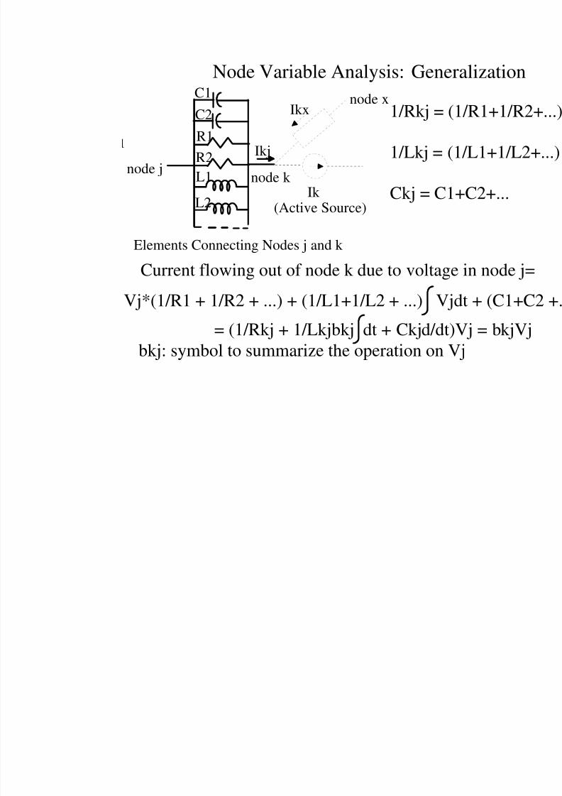
Node Variable Analysis: Generali
Current flowing out of node k due to voltage in
Vj*(1/R1 + 1/R2 + ...) + (1/L1+1/L2 + ...) Vjdt +
= (1/Rkj + 1/Lkjbkj dt + Ckjd/dt)Vj =
bkj: symbol to summarize the operation on Vj
C1C2
R1
R2
L1
L2
node jnode k
Elements Connecting Nodes j and k
1/Rkj = (1/R
1/Lkj = (1/L
Ckj = C1+C2
Ikj
node xIkx
Ik (Active Source)
8/4/2019 Network Notes IMP
http://slidepdf.com/reader/full/network-notes-imp 55/87
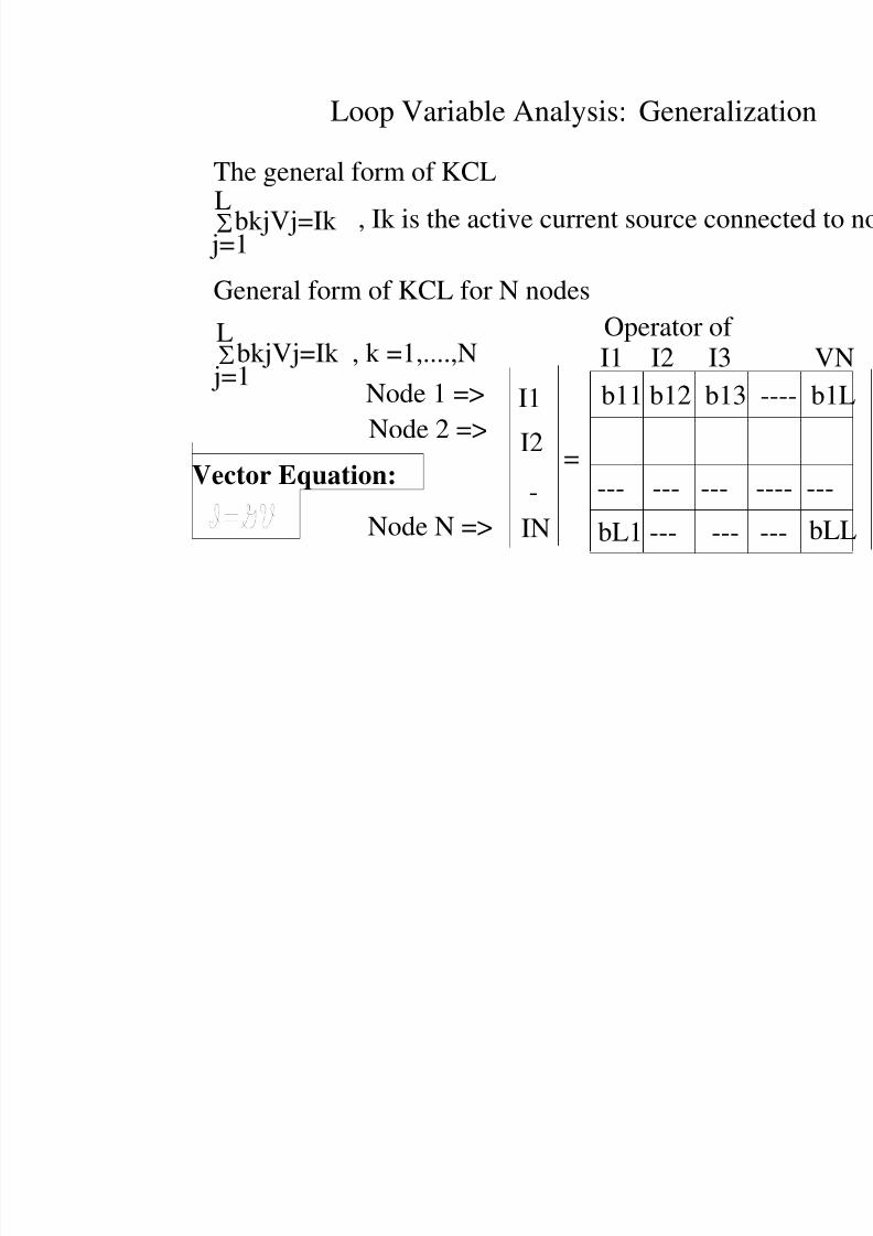
Loop Variable Analysis: Generali
The general form of KCL
bkjVj=Ik j=1
L
General form of KCL for N nodes
bkjVj=Ik , k =1,....,N j=1
L
b11 b12 b13
bL1 --- ---
--- --- ---
Operator of I1 I2 I3
I1
I2
IN
, Ik is the active current source con
Node 1 =>
Node 2 =>
Node N =>
-=Vector Equation:
8/4/2019 Network Notes IMP
http://slidepdf.com/reader/full/network-notes-imp 56/87
Node Variable Analysis:Identify the operators
=
-1 1/R1 0 C1d/dV/R1 +C1dV/dt
0 1/R2 -1/R2-1/R4-C3d/dt C3d/d
-V/R1
0 0 C3d/dt -1/R3-(C3+C1)d-C1d/dt
Note : There is no active current source.
0 -1/R2-1/R1-C2d/dt 1/R2 0
0
The voltage source V is equivalent to a current source Ib4 (voltage V (known)
=b12 =b13 =b14
=b22 =b23 =b24
=b32 =b33 =b34
=b42 =b43 =b44
8/4/2019 Network Notes IMP
http://slidepdf.com/reader/full/network-notes-imp 57/87
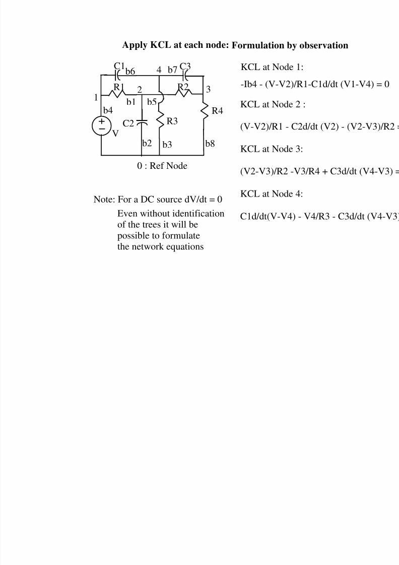
Apply KCL at each node: Formulation by observatio
0 : Ref Node
12
4
3
C1 C3
R1
C2 R3
b1
b2 b3
b4b5
b6 b7
R2
b8V
-Ib4 - (V-V2)/R1-C1d/dt KCL at Node 1:
KCL at Node 2 :
(V-V2)/R1 - C2d/dt (V2)
KCL at Node 3:
(V2-V3)/R2 -V3/R4 + C3
KCL at Node 4:
C1d/dt(V-V4) - V4/R3 - C
R4
Note: For a DC source dV/dt = 0
Even without identificationof the trees it will bepossible to formulatethe network equations
8/4/2019 Network Notes IMP
http://slidepdf.com/reader/full/network-notes-imp 58/87
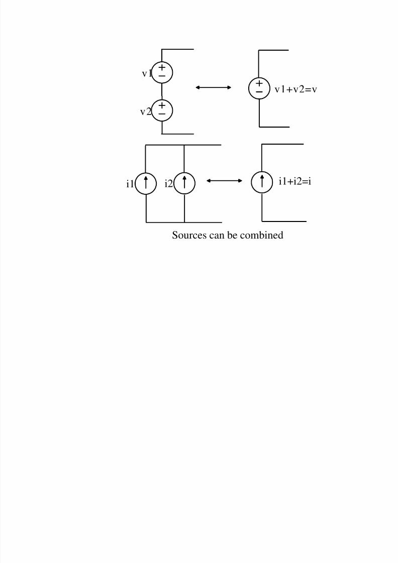
v1
v2
v1+v2=v
i1+i2=ii1 i2
Sources can be combined
8/4/2019 Network Notes IMP
http://slidepdf.com/reader/full/network-notes-imp 59/87
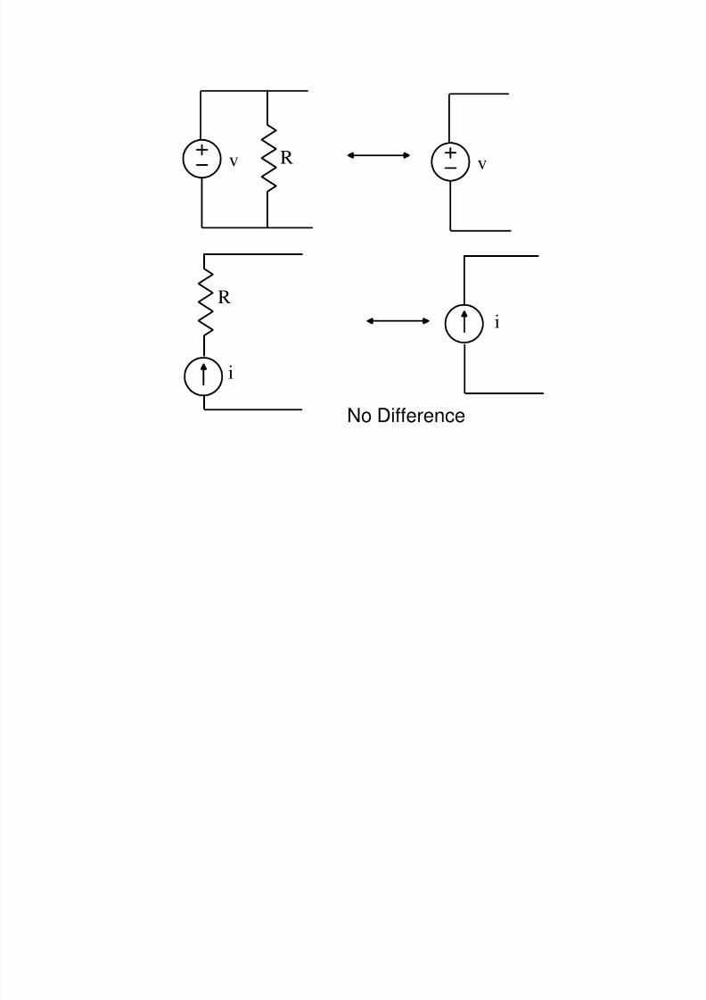
i
v vR
R
i
No Difference
8/4/2019 Network Notes IMP
http://slidepdf.com/reader/full/network-notes-imp 60/87
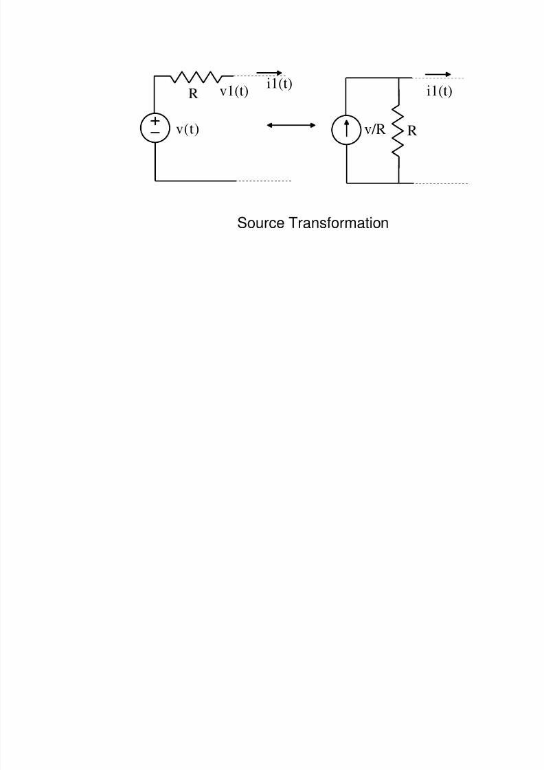
v(t)
R v1(t)
i1(t)
i1(t)
Rv/R
Source Transformation
8/4/2019 Network Notes IMP
http://slidepdf.com/reader/full/network-notes-imp 61/87
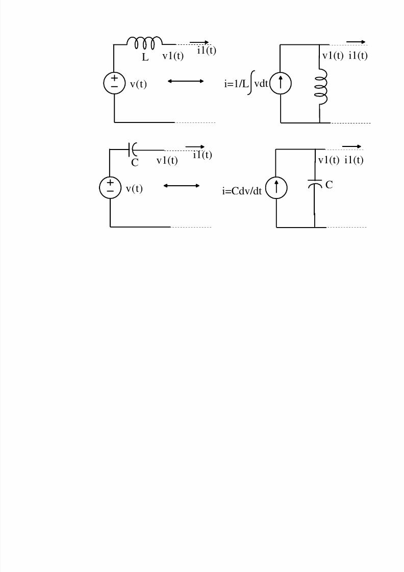
v(t)
v1(t)i1(t)
L
vdti=1/L
v1(t)
v(t)
v1(t)i1(t)
v1(t)
i=Cdv/dt
C
C
8/4/2019 Network Notes IMP
http://slidepdf.com/reader/full/network-notes-imp 62/87
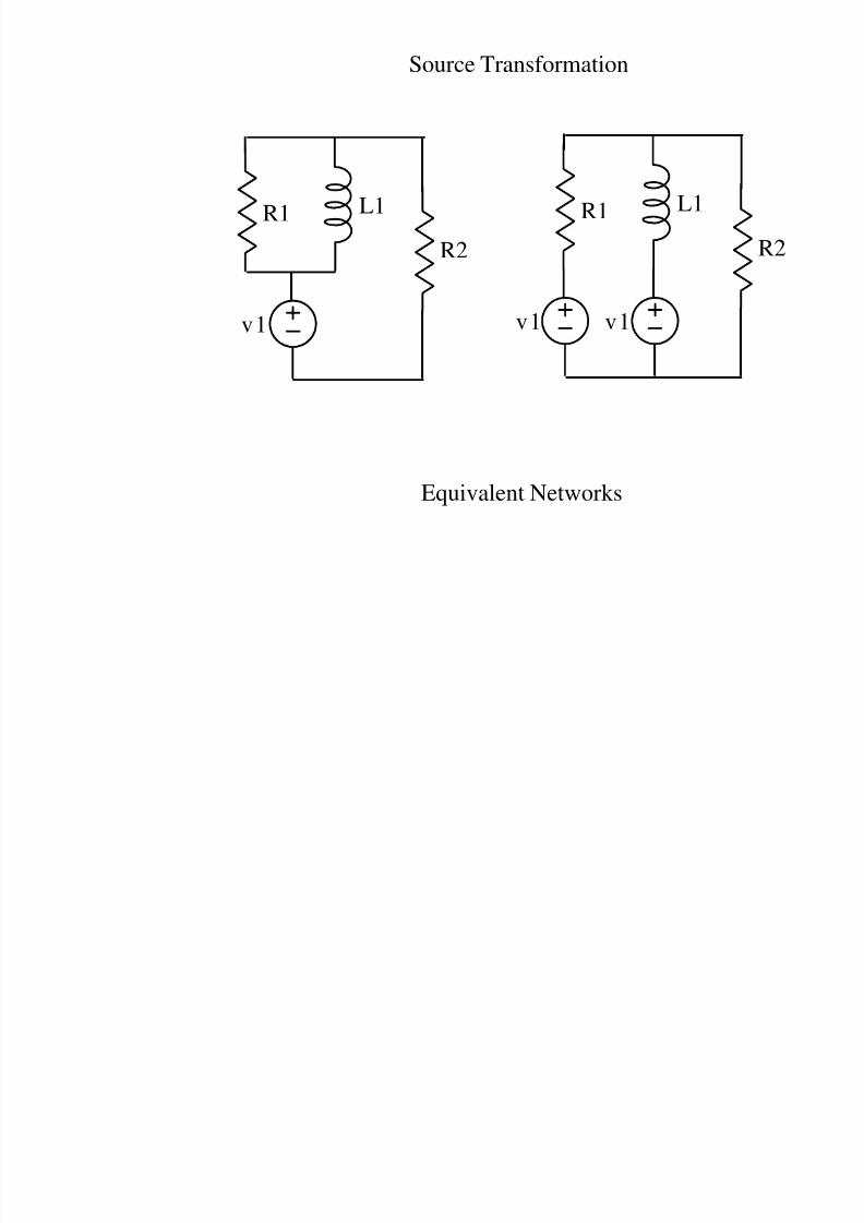
Source Transformation
Equivalent Networks
v1
R1
R2
L1
v1
R1 L1
v1
8/4/2019 Network Notes IMP
http://slidepdf.com/reader/full/network-notes-imp 63/87
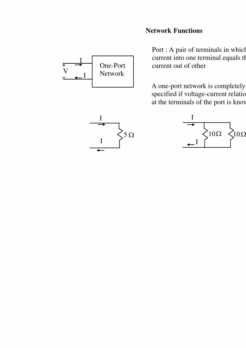
Network Functions
Port : A pair of termi
current into one term
current out of otherOne-Port
Network V
I
I
A one-port network ispecified if voltage-c
at the terminals of the
1
I
I5
I
I
8/4/2019 Network Notes IMP
http://slidepdf.com/reader/full/network-notes-imp 64/87
Network Functions
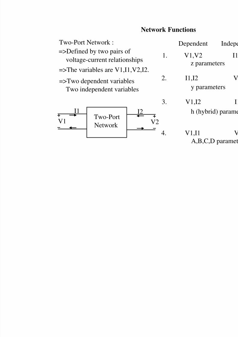
Two-Port Network :=>Defined by two pairs of
=>The variables are V1,I1,V2,I2.
Two-Port
Network V2
I2
V1
I1
voltage-current relationships
=>Two dependent variablesTwo independent variables
Depende
1. V1,V2
2. I1,I2
3. V1,I2
4. V1,I1
z par
y par
h (hy
A,B,
8/4/2019 Network Notes IMP
http://slidepdf.com/reader/full/network-notes-imp 65/87
Network Functions
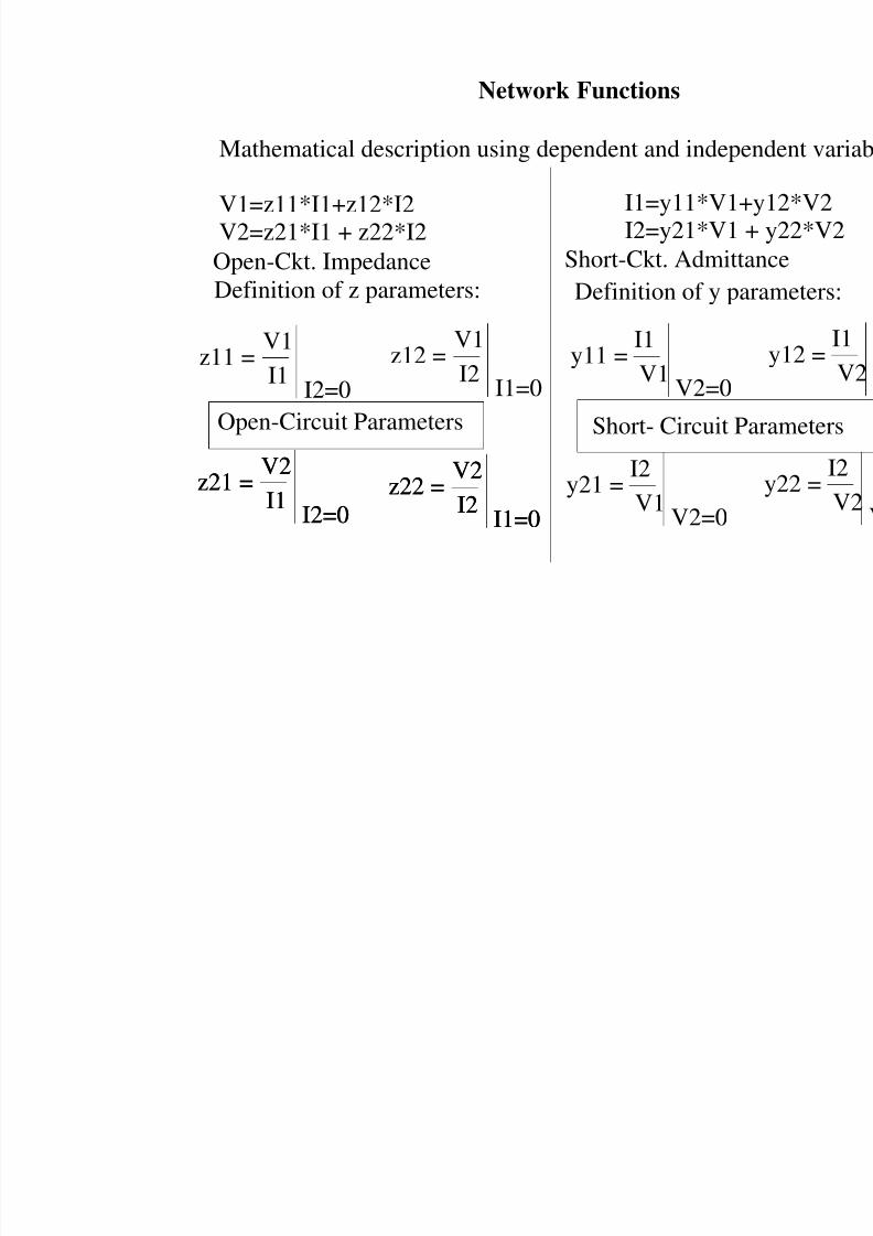
Mathematical description using dependent and indepe
V1=z11*I1+z12*I2V2=z21*I1 + z22*I2
z11 =V1
I1I2=0
z12 =V1
I2I1=0
Definition of z parameters:
z21 =V2
I1I2=0
z22 =V2
I2I1=0
I1=y11*V1+I2=y21*V1
Definition of y pa
z21 =V2
I1I2=0
z22 =V2
I2I1=0
Open-Circuit Parameters
y11 =I1
V1V2=0
y21 =I2
V1V2=0
Short- Circuit P
Short-Ckt. AdmittOpen-Ckt. Impedance
8/4/2019 Network Notes IMP
http://slidepdf.com/reader/full/network-notes-imp 66/87
Network Functions
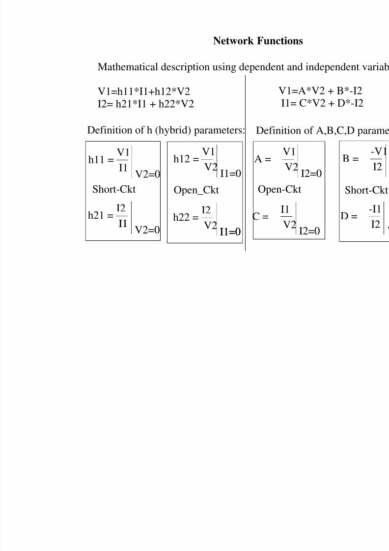
Mathematical description using dependent and indepe
V1=h11*I1+h12*V2I2= h21*I1 + h22*V2
h11 =V1
I1V2=0
h12 =V1
V2I1=0
Definition of h (hybrid) parameters:
h21 =I2
I1V2=0
h22 =I2
V2I1=0
I1
I1=0
Short-Ckt Open_Ckt
A =V1
V2I2=0
V1=A*V2 +I1= C*V2 +
Definition of A,B
C =I1
V2I2=0
Open-Ckt
8/4/2019 Network Notes IMP
http://slidepdf.com/reader/full/network-notes-imp 67/87
Network Functions
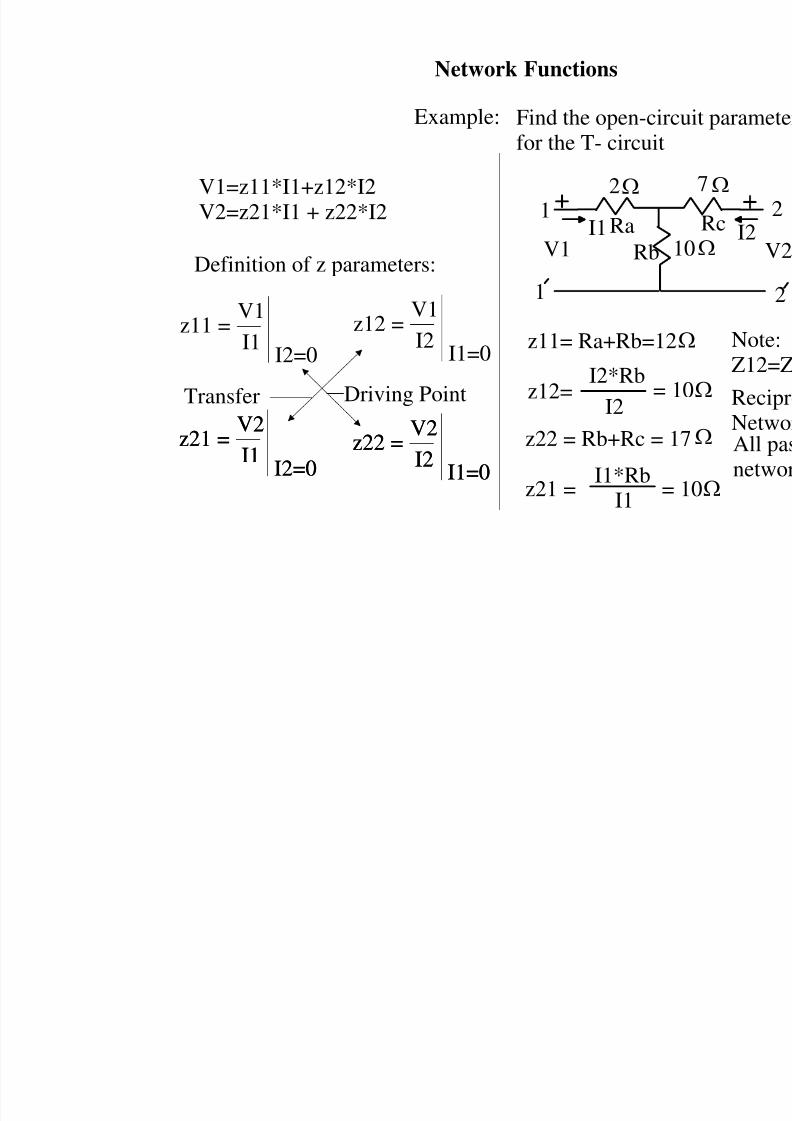
V1=z11*I1+z12*I2V2=z21*I1 + z22*I2
z11 =V1
I1I2=0
z12 =V1
I2I1=0
Definition of z parameters:
z21 =V2
I1I2=0
z22 =V2
I2I1=0
z21 =V2
I1I2=0
z22 =V2
I2I1=0
Find the open-circ
for the T- circuit
1
1
V1I1
2
z11= Ra+Rb=12
Ra
Rb
z12=I2*Rb
I2
= 1
z22 = Rb+Rc = 1
z21 =I1*Rb
I1=
Example:
Driving PointTransfer
8/4/2019 Network Notes IMP
http://slidepdf.com/reader/full/network-notes-imp 68/87
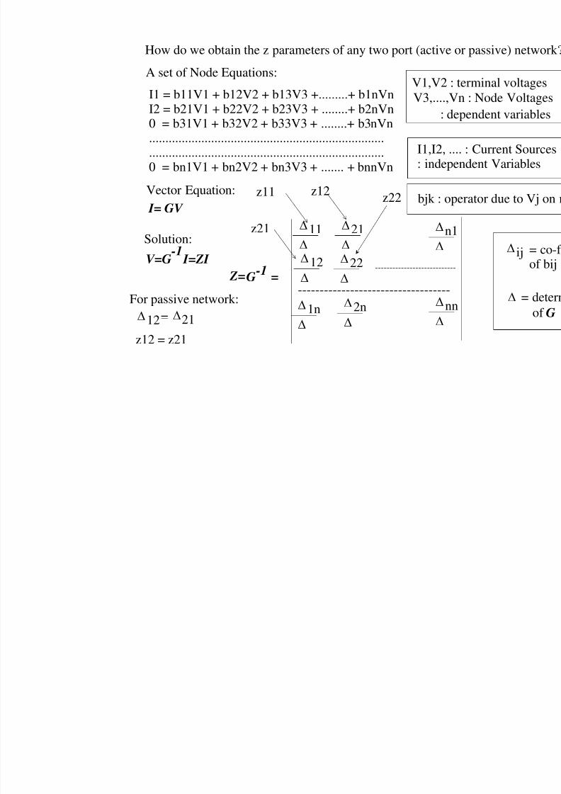
How do we obtain the z parameters of any two port (active or pa
I1 = b11V1 + b12V2 + b13V3 +.........+ b1nVnI2 = b21V1 + b22V2 + b23V3 + ........+ b2nVn0 = b31V1 + b32V2 + b33V3 + ........+ b3nVn................................................................................................................................................0 = bn1V1 + bn2V2 + bn3V3 + ....... + bnnVn
V3,....,Vn : N: depen
I1,I2, .... : C
A set of Node Equations:
: independe
bjk : operatVector Equation:
Solution:
I= GV
V=G-1
I=ZI
G-1
=
11
21
n1
12
1n
2n
nn-----------------------------------
----------------------------
Z=
z12z11
For passive network:
12= 21
z12 = z21
22
z21
z22
V1,V2 : term
8/4/2019 Network Notes IMP
http://slidepdf.com/reader/full/network-notes-imp 69/87
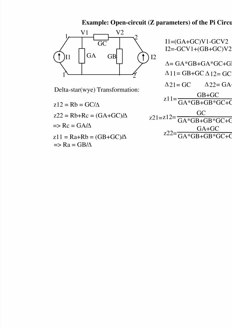
Example: Open-circuit (Z parameters) of
I2
1
1
2
2
V1 V2
I1 GA
GC
GB
I1=(GA+GCI2=-GCV1+
= GA*GB+
11= GB+G
21= GC
z11=G
GA*GB
z12=
z22=
z21=
Delta-star(wye) Transformation:
z12 = Rb = GC/
G
GA*GBG
GA*GB
z22 = Rb+Rc = (GA+GC)/
=> Rc = GA/
z11 = Ra+Rb = (GB+GC)/
=> Ra = GB/
8/4/2019 Network Notes IMP
http://slidepdf.com/reader/full/network-notes-imp 70/87
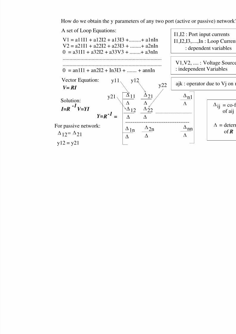
How do we obtain the y parameters of any two port (active or pa
V1 = a11I1 + a12I2 + a13I3 +.........+ a1nInV2 = a21I1 + a22I2 + a23I3 + ........+ a2nIn0 = a31I1 + a32I2 + a33V3 + ........+ a3nIn................................................................................................................................................0 = an1I1 + an2I2 + In3I3 + ....... + annIn
I1,I2,I3,....,In: depen
V1,V2, .... :
A set of Loop Equations:
: independe
ajk : operatoVector Equation:
Solution:
V= RI
I=R-1
V=YI
R-1
=
11
21
n1
12
1n
2n
nn-----------------------------------
----------------------------Y=
y12
For passive network:
12= 21
y12 = y21
I1,I2 : Port in
22
y21
y11 y22
8/4/2019 Network Notes IMP
http://slidepdf.com/reader/full/network-notes-imp 71/87
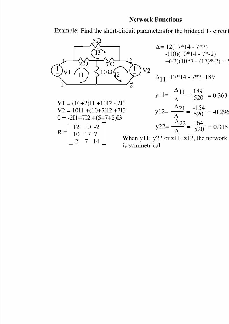
Network Functions
Find the short-circuit parameters for the bridgExample:
1
1 2
V1 V2I1 I2
2
10
7
2
I3
5
V1 = (10+2)I1 +10I2 - 2I3V2 = 10I1 +(10+7)I2 +7I3
0 = -2I1+7I2 +(5+7+2)I3
R =12 10 -210 17 7-2 7 14
11
= 12(17*14 - -(10)(10*14+(-2)(10*7
11=17*14 - 7
y11= =
15
21y12= =
-5
22y22= =
15
When y11=y22 or z11=z12,
is s mmetrical

8/4/2019 Network Notes IMP
http://slidepdf.com/reader/full/network-notes-imp 72/87
V1=h11*I1+h12*V2I2= h21*I1 + h22*V2
Definition of h (hybrid) parameters:
h11 = V1I1
V2=0
h12 = V1V2
I1=0
h21 =I2
I1V2=0
h22 =I2
V2 I1=0
I1
I1=0
Short-Ckt Open_Ckt
The h parameters : comparison
y11 =I1
V1 V2=0
=>
Extremely useful for describing bipolar junction trans
V1= Vbe = Base to em
I2 = Ic= Collector curI1= Ib = Base current
V2 = Vce = Collector
z22 =V2
I2I1=0
=> h
z12 =V1
I2 I1=0
=> h
=> h2y21 =I2
V1V2=0
8/4/2019 Network Notes IMP
http://slidepdf.com/reader/full/network-notes-imp 73/87
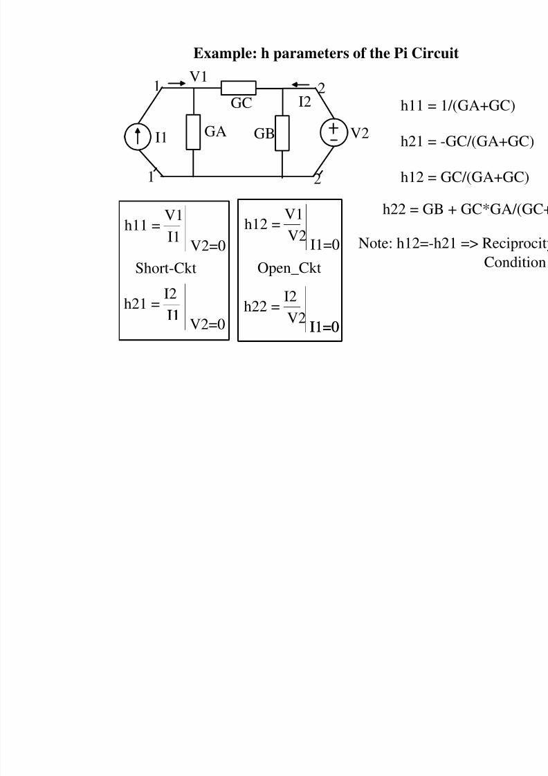
Example: h parameters of the Pi Circuit
1
1
2
2
V1
V2I1
I2
GA
GC
GB
h11 =V1
I1V2=0
h12 =V1
V2I1=0
h21 =I2
I1V2=0
h22 =I2
V2I1=0
I1
I1=0
Short-Ckt Open_Ckt
h11 = 1/(G
h21 = -GC
h12 = GC/
h22 = GB + G
Note: h12=-h21 =
8/4/2019 Network Notes IMP
http://slidepdf.com/reader/full/network-notes-imp 74/87
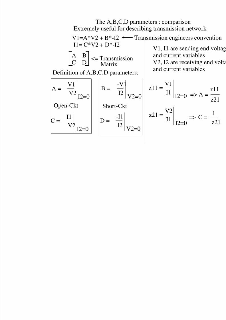
The A,B,C,D parameters : comparisonExtremely useful for describing transmission net
A =V1
V2I2=0
B =-V1
I2V2=0
V1=A*V2 + B*-I2I1= C*V2 + D*-I2
Definition of A,B,C,D parameters:
C = I1V2
I2=0
D = -I1I2
V2=0
Short-CktOpen-Ckt
V1, I1 are sendiand current variaV2, I2 are receivand current varia
A BC D
<= TransmissionMatrix
Transmission engineers
z11 =V1
I1I2=0
z21 =V2
I1 I2=0
z21 =V2
I1 I2=0
=
=
8/4/2019 Network Notes IMP
http://slidepdf.com/reader/full/network-notes-imp 75/87
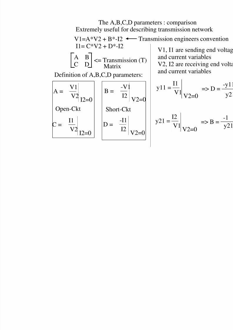
The A,B,C,D parameters : comparisonExtremely useful for describing transmission net
V1=A*V2 + B*-I2I1= C*V2 + D*-I2
A =V1
V2I2=0
B =-V1
I2V2=0
Definition of A,B,C,D parameters:
C = I1V2
I2=0
D = -I1I2
V2=0
Short-CktOpen-Ckt
V1, I1 are sendiand current variaV2, I2 are receivand current varia
A BC D
<= Transmission (T)Matrix
Transmission engineers
y11 =I1
V1V2=0
y21 =
I2
V1V2=0
8/4/2019 Network Notes IMP
http://slidepdf.com/reader/full/network-notes-imp 76/87
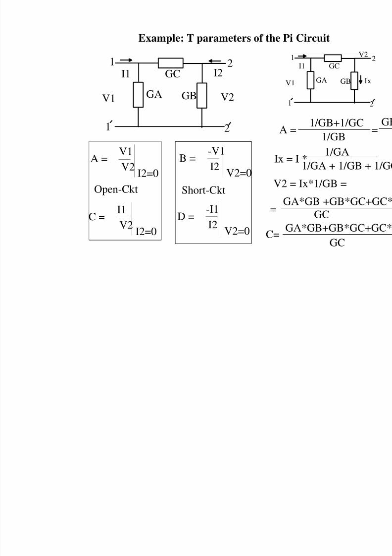
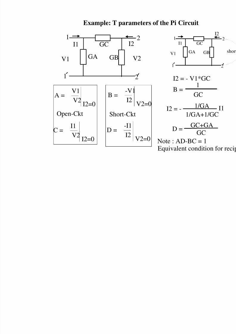
Example: T parameters of the Pi Circuit
1
1
2
2
V1 V2
I1 I2
GA
GC
GB
A =V1
V2I2=0
B =-V1
I2V2=0
C =I1
V2I2=0
D =-I1
I2V2=0
Short-CktOpen-Ckt
A =1/GB
1/G
1
1
V1
I1
GA
G
Ix = I *1/
1/GA +
GA*GB +GGC
C=GA*GB+G
G
V2 = Ix*1/GB
=
8/4/2019 Network Notes IMP
http://slidepdf.com/reader/full/network-notes-imp 77/87
Example: T parameters of the Pi Circuit
1
1
2
2
V1 V2
I1 I2
GA
GC
GB
A =V1
V2I2=0
B =-V1
I2V2=0
C =I1
V2I2=0
D =-I1
I2V2=0
Short-CktOpen-Ckt
1
1
V1
I1
GA
GC
I2 = - V1*
B =1
GC
I2 = - 1/G
1/GA+
D = GC+G
Note : AD-BC =Equivalent cond
8/4/2019 Network Notes IMP
http://slidepdf.com/reader/full/network-notes-imp 78/87
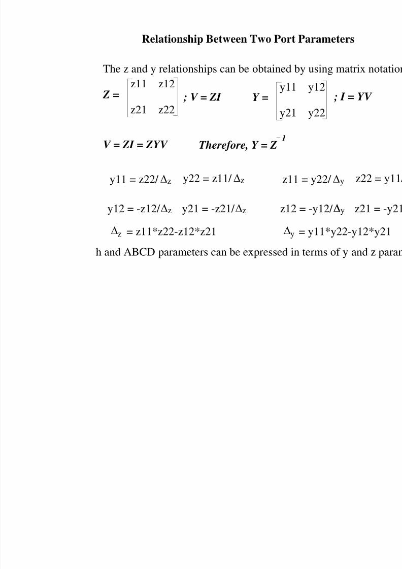
Relationship Between Two Port Paramete
The z and y relationships can be obtained by using m
Z =z11 z12
z21 z22Y =
y11 y12
y21 y22
V = ZI = ZYV
; V = ZI ; I
Therefore, Y = Z 1
y11 = z22/ z y22 = z11/ z
y12 = -z12/ z y21 = -z21/ z
z = z11*z22-z12*z21
z11 = y22/ y
z12 = -y12/ y
y = y11*y2
h and ABCD parameters can be expressed in terms of
8/4/2019 Network Notes IMP
http://slidepdf.com/reader/full/network-notes-imp 79/87
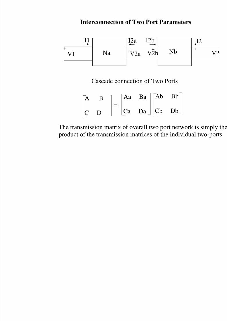
Interconnection of Two Port Parameters
Na NbV2a V2bV1
I1 I2a I2b
Cascade connection of Two Ports
Ab Bb
Cb Db
Aa Ba
Ca Da
Aa Ba
Ca Da
A B
C D
A=
The transmission matrix of overall two port networkproduct of the transmission matrices of the individua
8/4/2019 Network Notes IMP
http://slidepdf.com/reader/full/network-notes-imp 80/87
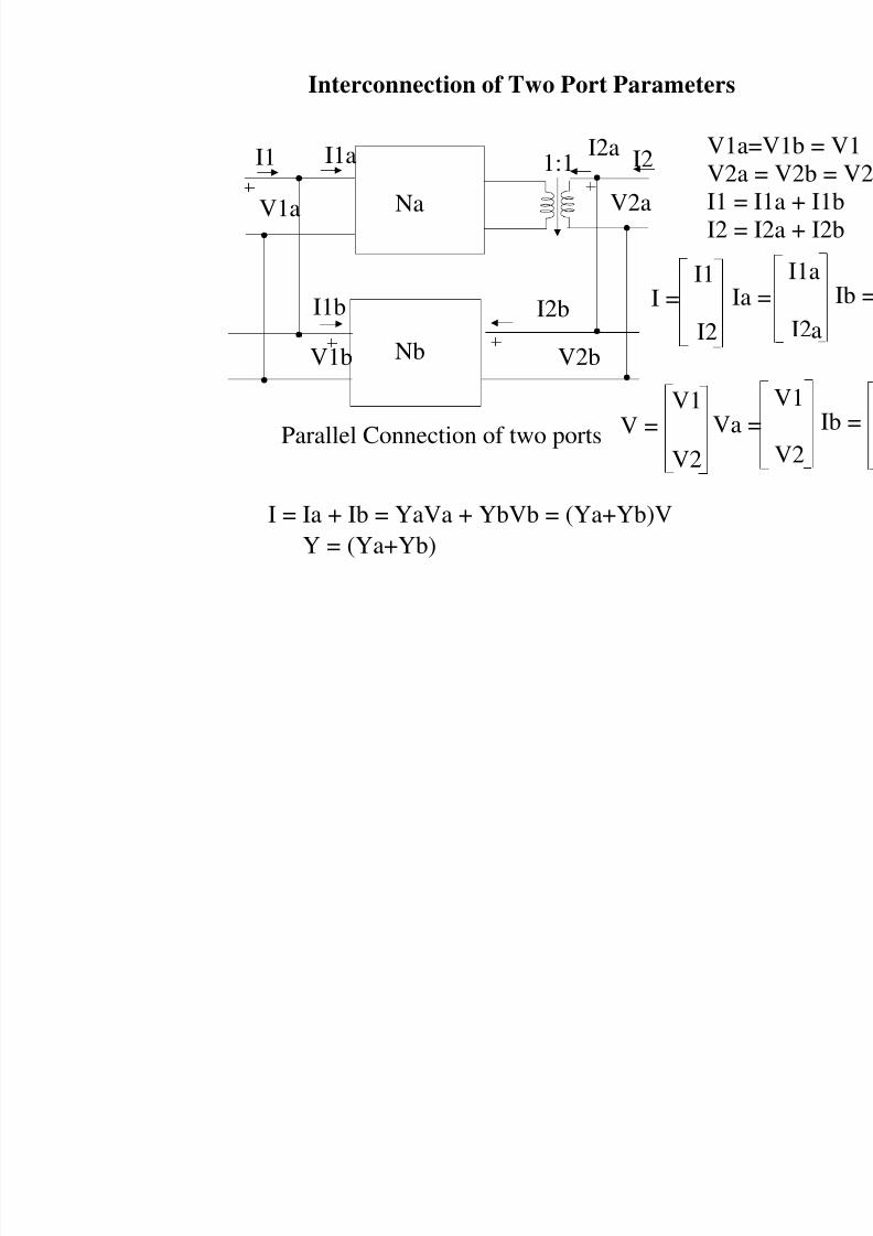
Interconnection of Two Port Parameters
Na V2aV1a
I1a I2a
Nb V2bV1b
I2bI1b
1:1
Parallel Connection of two ports
I1 I2 V1aV2aI1 =
I2 =
I =
I1
I2Ia
V =V1
V2
Va
I = Ia + Ib = YaVa + YbVb = (Ya+Yb)V
Y = (Ya+Yb)
8/4/2019 Network Notes IMP
http://slidepdf.com/reader/full/network-notes-imp 81/87
Interconnection of Two Port Parameters
Na V2aV1a
I1a I2a
Nb V2bV1b
I2bI1b
1:1
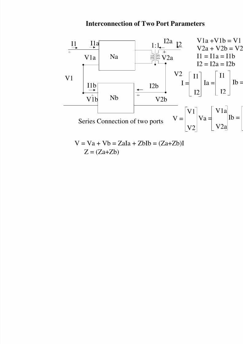
Series Connection of two ports
I1 I2 V1aV2aI1 =
I2 =
I =
I1
I2Ia
V =V1
V2
Va
V = Va + Vb = ZaIa + ZbIb = (Za+Zb)I
Z = (Za+Zb)
V1V2
8/4/2019 Network Notes IMP
http://slidepdf.com/reader/full/network-notes-imp 82/87
Interconnection of Two Port Parameters
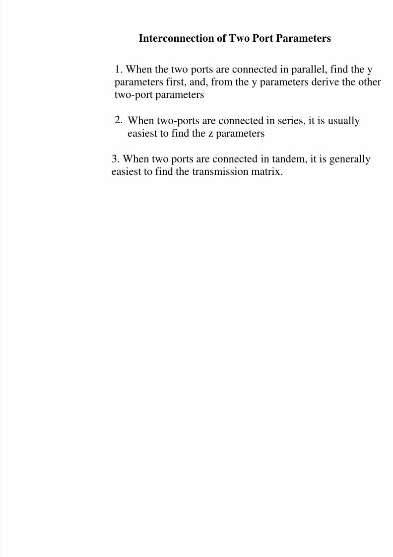
1. When the two ports are connected in parallel, fiparameters first, and, from the y parameters deriv
two-port parameters
2. When two-ports are connected in series, it is us
easiest to find the z parameters
3. When two ports are connected in tandem, it is geasiest to find the transmission matrix.
8/4/2019 Network Notes IMP
http://slidepdf.com/reader/full/network-notes-imp 83/87
Q5.
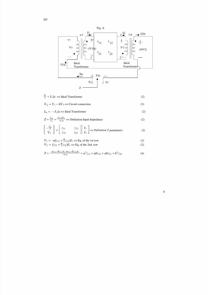
=> Ideal Transformer (2) I 2
b = I 1 / a
=> Circuit connection (2)V in = V 1 − bV 2
=> Ideal Transformer (2) I in = − I 1 / a
=> Definition Input Impedance (2) Z =V in I in
=V 1−bV 2
− I 1 / a
=> Definition Z parameters (2)−
V 1a
V 2=
z11 z12
z21 z22
I 1
I 2
=> Eq. of the 1st row (2)V 1 = −a( z11 +ba z12) I 1
=> Eq. of the 2nd. row (2)V 2 = ( z21 +
b
a z22) I 1
(4) Z =−a( z11+
ba z12) I 1−b( z21+
ba z22) I 1
− I 1 / a= a2 z11 + abz12 + abz21 + b2 z22
6
z z11 12
z z21 22
T1 T2
a:1 1:b1
1
2
2
Ideal
Transformer
Ideal
Transformer
Z
Fig. A
V1 -(V1/a) V2-(bV2)
VinIin
I1 I2
I1/a
I2/b
8/4/2019 Network Notes IMP
http://slidepdf.com/reader/full/network-notes-imp 84/87
Q6.
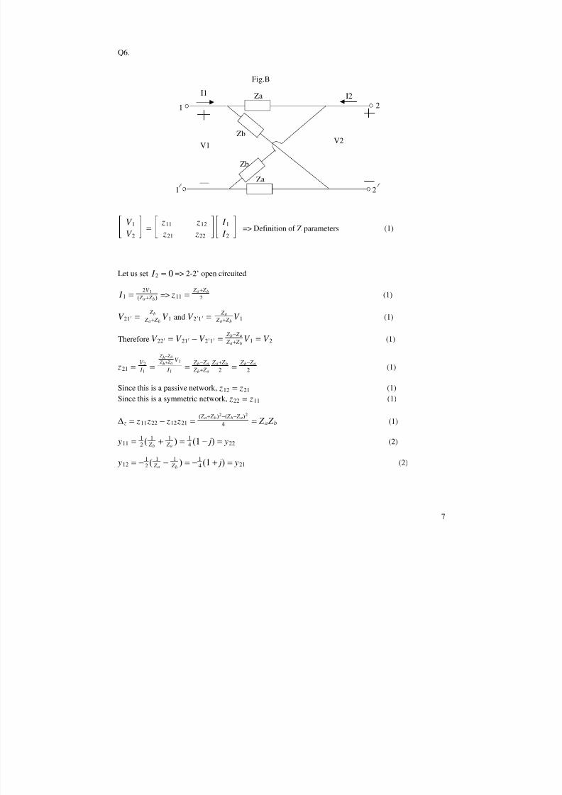
=> Definition of Z parameters (1)V 1
V 2=
z11 z12
z21 z22
I 1
I 2
Let us set => 2-2’ open circuited I 2 = 0
=> (1) I 1 =2V 1
( Z a+ Z b) z11 =Z a+ Z b
2
and (1)V 21∏ =Z b
Z a+ Z bV 1 V 2∏1 ∏ =
Z a Z a+ Z b
V 1
Therefore (1)V 22∏ = V 21∏ − V 2 ∏1∏ =Z b− Z a
Z a+ Z bV 1 = V 2
(1) z21 =V 2 I 1
=
Z b− Z a
Z b+ Z aV 1
I 1=
Z b− Z a
Z b+ Z a
Z a+ Z b2 =
Z b− Z a
2
Since this is a passive network, (1) z12
= z21
Since this is a symmetric network, (1) z22 = z11
(1) z = z11 z22 − z12 z21 =( Z a+ Z b)2−( Z b− Z a)2
4 = Z a Z b
(2) y11 =12 (
1 Z b
+1 Z a
) =14 (1 − j) = y22
(2) y12 = −12 (
1 Z a
−1
Z b) = −
14 (1 + j) = y21
7
Za
Za
1
1
2
2
Zb
Zb
Fig.B
V1V2
I1I2
8/4/2019 Network Notes IMP
http://slidepdf.com/reader/full/network-notes-imp 85/87
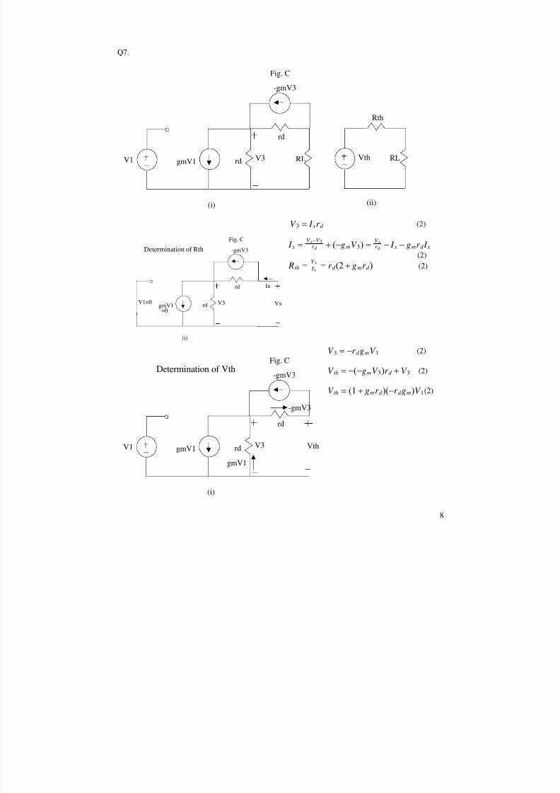
Q7.
(2)V 3 = I xr d
I x =V x−V 3r d + (−gmV 3) =
V xr d − I x − gmr d I x
(2)
(2) Rth =V x I x
= r d (2 + gmr d )
(2)V 3 = −r d gmV 1
(2)V th = −(−gmV 3)r d + V 3
(2)V th = (1 + gmr d )(−r d gm)V 1
8
V1 gmV1
-gmV3
rd
rd
RL RL
Rth
Vth
(i) (ii)
Fig. C
V3
gmV1
-gmV3
rd
rd
(i)
Fig. C
V3V1=0
=0
Vx
Ix
Determination of Rth
V1 gmV1
-gmV3
rd
rd
(i)
Fig. C
V3
Determination of Vth
Vth
-gmV3
gmV1
8/4/2019 Network Notes IMP
http://slidepdf.com/reader/full/network-notes-imp 86/87
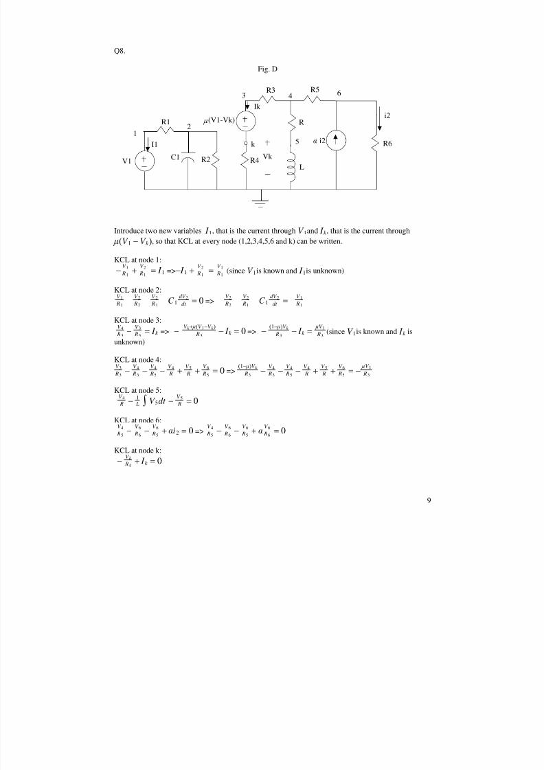
Q8.
Introduce two new variables , that is the current through and , that is the current through I 1 V 1 I k , so that KCL at every node (1,2,3,4,5,6 and k) can be written. (V 1 − V k )
KCL at node 1:
=> (since is known and is unknown)−V 1 R1
+V 2 R1
= I 1 − I 1 +V 2 R1
=V 1 R1
V 1 I 1
KCL at node 2:
=>V 1 R1
−V 2 R2
−V 2 R1
− C 1dV 2
dt = 0 −V 2 R2
−V 2 R1
− C 1dV 2
dt = −V 1 R1
KCL at node 3:
=> => (since is known and isV 4 R3
−V 3 R3
= I k −V k + (V 1−V k )
R3− I k = 0 −
(1− )V k R3
− I k =V 1
R3V 1 I k
unknown)
KCL at node 4:
=>V 3 R3
−V 4 R3
−V 4 R5
−V 4 R +
V 5 R +
V 6 R5
= 0(1− )V k
R3−
V 4 R3
−V 4 R5
−V 4 R +
V 5 R +
V 6 R5
= − V 1
R3
KCL at node 5:
V 4 R −
1 L ¶ V 5dt −
V 5 R = 0
KCL at node 6:
=>V 4 R5
−V 6 R6
−V 6 R5
+ i2 = 0V 4 R5
−V 6 R6
−V 6 R5
+ V 6 R6
= 0
KCL at node k:
−V k R4
+ I k = 0
9
V1
R1
C1 R2
R3 R5
R
L
R6
i2
R4
(V1-Vk)
k i2
Fig. D
Vk
12
3 4
5
6
I1
Ik
8/4/2019 Network Notes IMP
http://slidepdf.com/reader/full/network-notes-imp 87/87
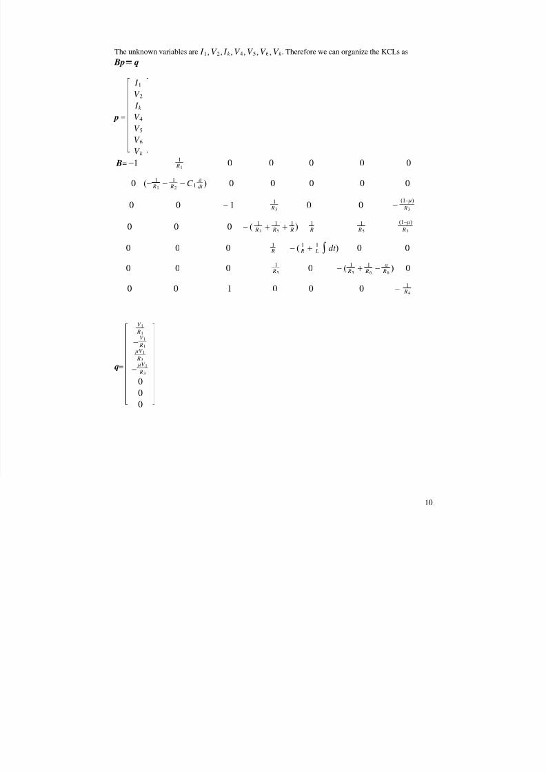
The unknown variables are . Therefore we can organize the KCLs as I 1,V 2, I k ,V 4,V 5,V 6,V k Bp = q
= p
I 1
V 2 I k
V 4
V 5
V 6
V k
= B −11
R10 0 0 0 0
0 (−1
R1−
1 R2
− C 1d
dt ) 0 0 0 0 0
0 0 − 11
R30 0 −
(1− )
R3
0 0 0 − (1
R3+
1 R5
+1 R )
1 R
1 R5
(1− )
R3
0 0 01 R − (
1 R +
1 L ¶ dt ) 0 0
0 0 01
R50 − (
1 R5
+1
R6−
R6
) 0
0 0 1 0 0 0 − 1 R4
=q
V 1 R1
−V 1 R1
V 1
R3
− V 1
R3
00