Embed Size (px)
Citation preview


Network Mergers and Migrations

WILEY SERIES IN COMMUNICATIONS NETWORKING & DISTRIBUTEDSYSTEMS
Series Editor: David Hutchison, Lancaster University, Lancaster, UKSerge Fdida, Universitè Pierre et Marie Curie, Paris, FranceJoe Sventek, University of Glasgow, Glasgow, UK
The ‘Wiley Series in Communications Networking & Distributed Systems’ is a seriesof expert-level, technically detailed books covering cutting-edge research, and brand newdevelopments as well as tutorial-style treatments in networking, middleware and softwaretechnologies for communications and distributed systems. The books will provide timelyand reliable information about the state-of-the-art to researchers, advanced students anddevelopment engineers in the Telecommunications and the Computing sectors.
Other titles in the series:
Wright: Voice over Packet Networks 0-471-49516-6 (February 2001)Jepsen: Java for Telecommunications 0-471-49826-2 (July 2001)Sutton: Secure Communications 0-471-49904-8 (December 2001)Stajano: Security for Ubiquitous Computing 0-470-84493-0 (February 2002)Martin-Flatin: Web-Based Management of IP Networks and Systems 0-471-48702-3(September 2002)Berman, Fox, Hey: Grid Computing. Making the Global Infrastructure a Reality0-470-85319-0 (March 2003)Turner, Magill, Marples: Service Provision. Technologies for Next GenerationCommunications 0-470-85066-3 (April 2004)Welzl: Network Congestion Control: Managing Internet Traffic 0-470-02528-X (July 2005)Raz, Juhola, Serrat-Fernandez, Galis: Fast and Efficient Context-Aware Services0-470-01668-X (April 2006)Heckmann: The Competitive Internet Service Provider 0-470-01293-5 (April 2006)Dressler: Self-Organization in Sensor and Actor Networks 0-470-02820-3 (November 2007)Berndt: Towards 4G Technologies: Services with Initiative 0-470-01031-2 (March 2008)Jacquenet, Bourdon, Boucadair: Service Automation and Dynamic Provisioning Techniquesin IP/MPLS Environments 0-470-01829-1 (March 2008)Minei/Lucek: MPLS-Enabled Applications: Emerging Developments and NewTechnologies, Second Edition 0-470-98644-1 (April 2008)Gurtov: Host Identity Protocol (HIP): Towards the Secure Mobile Internet 0-470-99790-7(June 2008)Boucadair: Inter-Asterisk Exchange (IAX): Deployment Scenarios in SIP-enabled Networks0-470-77072-4 (January 2009)Fitzek: Mobile Peer to Peer (P2P): A Tutorial Guide 0-470-69992-2 (June 2009)Shelby: 6LoWPAN: The Wireless Embedded Internet 0-470-74799-4 (November 2009)Stavdas: Core and Metro Networks 0-470-51274-1 (February 2010)

Network Mergers andMigrations:
Junos� Design and Implementation
Gonzalo Gómez Herrero
Professional Services, Juniper Networks, Inc
Jan Antón Bernal van der Ven
Professional Services, Juniper Networks, Inc
A John Wiley and Sons, Ltd, Publication

This edition first published 2010c© 2010 John Wiley & Sons Ltd
Registered officeJohn Wiley & Sons Ltd, The Atrium, Southern Gate, Chichester, West Sussex, PO19 8SQ,United Kingdom
For details of our global editorial offices, for customer services and for information about how to applyfor permission to reuse the copyright material in this book please see our website at www.wiley.com.
The right of the author to be identified as the author of this work has been asserted in accordance withthe Copyright, Designs and Patents Act 1988.
All rights reserved. No part of this publication may be reproduced, stored in a retrieval system, ortransmitted, in any form or by any means, electronic, mechanical, photocopying, recording orotherwise, except as permitted by the UK Copyright, Designs and Patents Act 1988, without the priorpermission of the publisher.
Wiley also publishes its books in a variety of electronic formats. Some content that appears in printmay not be available in electronic books.
Designations used by companies to distinguish their products are often claimed as trademarks. Allbrand names and product names used in this book are trade names, service marks, trademarks orregistered trademarks of their respective owners. The publisher is not associated with any product orvendor mentioned in this book. This publication is designed to provide accurate and authoritativeinformation in regard to the subject matter covered. It is sold on the understanding that the publisher isnot engaged in rendering professional services. If professional advice or other expert assistance isrequired, the services of a competent professional should be sought.
Library of Congress Cataloging-in-Publication Data
CIP data to follow
A catalogue record for this book is available from the British Library.
ISBN 9780470742372 (PB)
Set in 10/12pt Times by Sunrise Setting Ltd, Torquay, UK.Printed and Bound in Great Britain by Antony Rowe, Chippenham, Wiltshire.

Advanced Praise for Network Mergers and Migrations
“Having been through the network migrations of both SBC-Ameritech, and SBC-AT&T, this book providesvaluable direction and advice to an operator that would be useful when dealing with mergers andmigrations. It is about time that someone wrote a book covering not just green field network design, buthow do you merge networks together while maintaining the needs of the business.”
Tom Scholl, Principal IP Network Engineer, IP/MPLS Backbone Design and Development, AT&T Labs
“I have never read such an excellent book detailing so much about Juniper router operation and designknowledge in depth, not only it has helped me with operating all of our Juniper routers in our nationalbackbone network more efficiently, but also on improving my design knowledge as well.”
Ji Hui, Senior Manager, China Telecom Group Corporation
“Network Mergers and Migrations gives a clear idea of the difficulty of merging or migrating IP networks,and it is a great help for engineers that have to face this type of operation for the first time or evenrepeatedly.”
Chiara Moriondo, Senior Engineer, Telecom Italia Labs
“Network Mergers and Migrations provides an original approach to IP and MPLS instruction that is righton target. When combined with the depth of technical information and case studies contained within, theresult is an irreplaceable resource for any network engineer.”
Chris Grundemann, Senior Engineer, tw telecom, inc.
“Network Mergers and Migrations is a thorough guide for anyone involved in a wide range of networkconsolidation and integration exercises. The authors use Junos as a technical focus for their exampleskeeping the concepts related to some of the more relevant protocols and topics in current IP and MPLSnetworks. It’s a must-have book for anyone wishing to further enhance their protocol knowledge base.”
Shafik Hirjee, Bell Canada, Director, National MPLS/IP Core Network Engineering
“We operate the largest R&E network in the world using Juniper T640s, and my job often involves networkplanning and design. I have found this book to be just the one I need. I thought I knew Junos, but theseauthors are at an unprecedented level.”
Zheng Zhiyan, Senior Engineer, Network Operation Center, CNGI-6IX/CERNET2
“Recommended reading for networkers who like to look into complex and detailed network migrationscenarios, as well as those interested in a better understanding of Junos implementation of common ISPprotocols.”
Andreas Weiner, Network Engineer/IP Backbone, Telekom Austria TA AG
“Network Mergers and Migrations provides network operators a comprehensive reference for networkmigration. The level of detail included in this book is exceptional. It’s a thorough guide for any networkprofessional who are involved with network migration.”
Mazen A. Baragaba & Eid Al Harbi Communications Engineers, Communications Operations Depart-ment, Saudi Aramco

“Efficient IP network planning and management involves more than just the in-depth knowledge oftheory. This book helps the reader gain a thorough understanding of the Junos routing architecture viapractical and useful case studies, resulting in smooth and clean transitions between different networkimplementations. The clear and concise exposition make this book a pleasure to read and a usefulcompanion during work.”
Giorgio Lembo, R&D Director, Tinet S.p.A.
“Network Mergers and Migrations describes in detail the basics of L3VPN architectures while providinga clear and detailed roadmap for various migration scenarios. Even for telcos (operators) that are notimplied in migration phases, a lot of great advice is provided for designing network architectures basedon Junos software.”
David Roy, Orange France, RBCI IP Technical Assistance Center
“Network Mergers and Migrations is much more than a reference for all relevant IP protocols today, it isa book of practical examples for your daily work and should be on the desk of everyone who has to dealwith network migrations and mergers.”
Christian Kaufmann, Senior Manager Network Architecture, Akamai Technology
“An invaluable guide for anyone about to undertake a network merger, full of appropriate case studies andJunos tips to back up the concepts discussed.”
Keith Slater, NOC Manager, Cable&Wireless Worldwide
“The best book on operating Junos router networks!”
Jia Yan, Director, Network Maintenance Center, China Telecom Group Beijing Corporation
“Sooner or later in their careers, network professionals will be faced with a network merger or migration.This book covers all technical aspects of the problems encountered during a migration or merger andprovides the best practices and techniques on how to perform the task with the minimal impact on customerservices. A must have in any network professional’s library.”
Otto Kreiter, Service Introduction Manager, DANTE Ltd.

Contents
List of Junos Tips xiii
List of Application Notes xv
List of “What ifs” xvii
About the Authors xix
Series Foreword xxi
Foreword xxiii
Acknowledgments xxv
Acronyms xxvii
Introduction xxxi
1 Dealing with Routes within a Junos OS Based Router 11.1 Route Handling Features inside a Junos OS Based Router . . . . . . . . . . . 1
1.1.1 Instances and RIB tables . . . . . . . . . . . . . . . . . . . . . . . . 21.1.2 Grouping RIBs together . . . . . . . . . . . . . . . . . . . . . . . . 51.1.3 Instructing protocols to use different RIBs . . . . . . . . . . . . . . . 81.1.4 Automatic RIB groups and VPN routes . . . . . . . . . . . . . . . . 101.1.5 Local redistribution using the vrf-import option . . . . . . . . . . . . 12
1.2 RIB Route Advertisement at MPLS Layer 3 VPNs . . . . . . . . . . . . . . 131.2.1 Levels of advertisement policy – vpn-apply-export . . . . . . . 141.2.2 Path selection mode in Junos OS . . . . . . . . . . . . . . . . . . . . 151.2.3 RIB group versus auto-exported routes . . . . . . . . . . . . . . . . 171.2.4 RIB selection – no-vrf-advertise . . . . . . . . . . . . . . . . 17
1.3 Directing Traffic to Forwarding Tables . . . . . . . . . . . . . . . . . . . . . 181.3.1 Adding a routing table next hop to a static route . . . . . . . . . . . . 181.3.2 Using packet filtering to control the forwarding process . . . . . . . . 191.3.3 Usage guidelines . . . . . . . . . . . . . . . . . . . . . . . . . . . . 191.3.4 Risks of decoupling routing and forwarding . . . . . . . . . . . . . . 20

viii CONTENTS
1.4 Case Study . . . . . . . . . . . . . . . . . . . . . . . . . . . . . . . . . . . 211.4.1 Original network . . . . . . . . . . . . . . . . . . . . . . . . . . . . 211.4.2 Target network . . . . . . . . . . . . . . . . . . . . . . . . . . . . . 231.4.3 Migration strategy . . . . . . . . . . . . . . . . . . . . . . . . . . . 241.4.4 Stage one: Building an MPLS L3VPN . . . . . . . . . . . . . . . . . 271.4.5 Stage two: Preparatory work at spoke sites . . . . . . . . . . . . . . 301.4.6 Stage three: Preparatory work at headquarters . . . . . . . . . . . . . 311.4.7 Stage four: Preparatory work at the data center . . . . . . . . . . . . 371.4.8 Stage five: Move of data center site to CORP VRF . . . . . . . . . . 421.4.9 Stage six: Moving first spoke site router Inverness to CORP VRF . . 481.4.10 Stage seven: Monitoring and anomaly detection . . . . . . . . . . . . 481.4.11 Stage eight: Move of remaining spoke sites to CORP VRF . . . . . . 511.4.12 Stage nine: Hub traffic to data center to follow CORP VPN . . . . . . 551.4.13 Stage ten: Migration cleanup . . . . . . . . . . . . . . . . . . . . . . 561.4.14 Migration summary . . . . . . . . . . . . . . . . . . . . . . . . . . . 58
Bibliography . . . . . . . . . . . . . . . . . . . . . . . . . . . . . . . . . . . . . 58Further Reading . . . . . . . . . . . . . . . . . . . . . . . . . . . . . . . . . . . . 59
2 Link-State IGP Migrations 612.1 Link-state IGP Hierarchical Migrations . . . . . . . . . . . . . . . . . . . . 63
2.1.1 Motivations for link-state IGP hierarchical migrations . . . . . . . . 632.1.2 Generic strategies for link-state IGP hierarchical migrations . . . . . 672.1.3 Resources for link-state IGP hierarchical migrations . . . . . . . . . 92
2.2 Link-state IGP Domain Migrations . . . . . . . . . . . . . . . . . . . . . . . 1092.2.1 Considerations for a link-state IGP migration . . . . . . . . . . . . . 1092.2.2 Generic strategies for a link-state IGP migration . . . . . . . . . . . 1142.2.3 Resources for a link-state IGP migration . . . . . . . . . . . . . . . . 118
2.3 Case Study . . . . . . . . . . . . . . . . . . . . . . . . . . . . . . . . . . . 1482.3.1 Original network . . . . . . . . . . . . . . . . . . . . . . . . . . . . 1492.3.2 Target network . . . . . . . . . . . . . . . . . . . . . . . . . . . . . 1502.3.3 Migration strategy . . . . . . . . . . . . . . . . . . . . . . . . . . . 1532.3.4 Stage one: IS–IS Level 2 activation in domain “Cyclone” . . . . . . . 1542.3.5 Stage two: Route redistribution at domain “Monsoon” . . . . . . . . 1662.3.6 Stage three: IS–IS protocol adaption at domain “Mistral” . . . . . . . 1772.3.7 Stage four: Domain interconnection via IS–IS Level 2 . . . . . . . . 1852.3.8 Stage five: Integration of router Lille in the IS–IS domain . . . . . . 1862.3.9 Stage six: Global connectivity verification . . . . . . . . . . . . . . . 1912.3.10 Stage seven: OSPFv2 to IS–IS Level 2 transition in
domain “Cyclone” . . . . . . . . . . . . . . . . . . . . . . . . . . . 2032.3.11 Stage eight: Address renumbering and OSPFv2 replacement with
IS–IS in domain “Monsoon” . . . . . . . . . . . . . . . . . . . . . . 2102.3.12 Stage nine: IS–IS Level 1 authentication and route-leaking adaption
in domain “Mistral” and router Lille . . . . . . . . . . . . . . . . . . 2212.3.13 Migration summary . . . . . . . . . . . . . . . . . . . . . . . . . . . 223
Bibliography . . . . . . . . . . . . . . . . . . . . . . . . . . . . . . . . . . . . . 226Further Reading . . . . . . . . . . . . . . . . . . . . . . . . . . . . . . . . . . . . 227

CONTENTS ix
3 BGP Migrations 2293.1 Motivations for BGP Migrations . . . . . . . . . . . . . . . . . . . . . . . . 2313.2 Considerations for BGP Migrations . . . . . . . . . . . . . . . . . . . . . . 233
3.2.1 Protocol messages . . . . . . . . . . . . . . . . . . . . . . . . . . . 2343.2.2 Capability advertisement . . . . . . . . . . . . . . . . . . . . . . . . 2363.2.3 Address families . . . . . . . . . . . . . . . . . . . . . . . . . . . . 2373.2.4 Implications of public AS change . . . . . . . . . . . . . . . . . . . 2383.2.5 AS numbers in route advertisements . . . . . . . . . . . . . . . . . . 2393.2.6 AS-related attributes in advertisements . . . . . . . . . . . . . . . . 2403.2.7 Internal peering topologies . . . . . . . . . . . . . . . . . . . . . . . 2423.2.8 Keep last active route with BGP equal cost external paths . . . . . . 2453.2.9 Grouping policy with communities . . . . . . . . . . . . . . . . . . 2463.2.10 Handling of protocol next-hop changes . . . . . . . . . . . . . . . . 246
3.3 Generic Strategies for BGP Migrations . . . . . . . . . . . . . . . . . . . . . 2483.3.1 Leverage protocol layering . . . . . . . . . . . . . . . . . . . . . . . 2493.3.2 Adding redundancy . . . . . . . . . . . . . . . . . . . . . . . . . . . 2493.3.3 Scalability . . . . . . . . . . . . . . . . . . . . . . . . . . . . . . . 2493.3.4 Beware of IP routers in transit . . . . . . . . . . . . . . . . . . . . . 2503.3.5 Coordinating external peering changes . . . . . . . . . . . . . . . . . 2503.3.6 Best-path selection . . . . . . . . . . . . . . . . . . . . . . . . . . . 2513.3.7 Changing IBGP topologies . . . . . . . . . . . . . . . . . . . . . . . 251
3.4 Junos OS Implementation of BGP . . . . . . . . . . . . . . . . . . . . . . . 2533.4.1 Inbound . . . . . . . . . . . . . . . . . . . . . . . . . . . . . . . . . 2533.4.2 Adj-RIB-In . . . . . . . . . . . . . . . . . . . . . . . . . . . . . . . 2543.4.3 Loc-RIB . . . . . . . . . . . . . . . . . . . . . . . . . . . . . . . . 2553.4.4 Adj-RIB-Out . . . . . . . . . . . . . . . . . . . . . . . . . . . . . . 255
3.5 Resources for Junos OS BGP Migrations . . . . . . . . . . . . . . . . . . . . 2573.5.1 Advertisement of inactive BGP routes . . . . . . . . . . . . . . . . . 2573.5.2 Flexible identification of the local AS . . . . . . . . . . . . . . . . . 2573.5.3 Allowing for AS loops . . . . . . . . . . . . . . . . . . . . . . . . . 260
3.6 Case Study . . . . . . . . . . . . . . . . . . . . . . . . . . . . . . . . . . . 2603.6.1 Original network . . . . . . . . . . . . . . . . . . . . . . . . . . . . 2603.6.2 Target network . . . . . . . . . . . . . . . . . . . . . . . . . . . . . 2653.6.3 Migration strategy . . . . . . . . . . . . . . . . . . . . . . . . . . . 2663.6.4 Stage one: Confederating domain “Cyclone” . . . . . . . . . . . . . 2683.6.5 Stage two: Confederating domain “Mistral” . . . . . . . . . . . . . . 2733.6.6 Stage three: First confederation peering to bind both sub-AS domains
together . . . . . . . . . . . . . . . . . . . . . . . . . . . . . . . . . 2773.6.7 Stage four: Monitoring period . . . . . . . . . . . . . . . . . . . . . 2783.6.8 Stage five: CBGP deployment and EBGP cleanup between domain
“Cyclone” and domain “Mistral” . . . . . . . . . . . . . . . . . . . . 2843.6.9 Stage six: External peering on new 4-byte AS . . . . . . . . . . . . . 2853.6.10 Stage seven: Bringup IBGP peerings to Lille . . . . . . . . . . . . . 2883.6.11 Stage eight: Enable route reflection on router Lille . . . . . . . . . . 2923.6.12 Stage nine: Switch router Nantes to the 4-byte AS . . . . . . . . . . . 2923.6.13 Stage ten: Monitor . . . . . . . . . . . . . . . . . . . . . . . . . . . 294

x CONTENTS
3.6.14 Stage eleven: Roll out and cleanup . . . . . . . . . . . . . . . . . . . 2943.6.15 Migration summary . . . . . . . . . . . . . . . . . . . . . . . . . . . 294
Bibliography . . . . . . . . . . . . . . . . . . . . . . . . . . . . . . . . . . . . . 294Further Reading . . . . . . . . . . . . . . . . . . . . . . . . . . . . . . . . . . . . 295
4 MPLS label distribution Migrations 2974.1 Motivations for MPLS label distribution Migrations . . . . . . . . . . . . . . 2974.2 Considerations for MPLS label distribution Migrations . . . . . . . . . . . . 2984.3 Generic Strategies for an MPLS label distribution protocol Migration . . . . . 300
4.3.1 MPLS label distribution protocol coexistence . . . . . . . . . . . . . 3004.3.2 MPLS label distribution protocol redistribution . . . . . . . . . . . . 3014.3.3 MPLS label distribution protocol overlay . . . . . . . . . . . . . . . 3034.3.4 MPLS label distribution protocol parameterization . . . . . . . . . . 303
4.4 Resources for an MPLS label distribution protocol Migration . . . . . . . . . 3044.4.1 MPLS label distribution protocol preference . . . . . . . . . . . . . . 3054.4.2 Resources to control LDP label distribution . . . . . . . . . . . . . . 3064.4.3 Resources for route installation with RSVP-TE . . . . . . . . . . . . 3124.4.4 Resources for label advertisement and route resolution with Labeled
BGP . . . . . . . . . . . . . . . . . . . . . . . . . . . . . . . . . . . 3214.5 Case Study . . . . . . . . . . . . . . . . . . . . . . . . . . . . . . . . . . . 324
4.5.1 Original network . . . . . . . . . . . . . . . . . . . . . . . . . . . . 3244.5.2 Target network . . . . . . . . . . . . . . . . . . . . . . . . . . . . . 3264.5.3 Migration strategy . . . . . . . . . . . . . . . . . . . . . . . . . . . 3274.5.4 Stage one: Labeled BGP deployment over LDP in domain “Mistral” 3314.5.5 Stage two: Labeled BGP deployment over RSVP-TE in domain
“Cyclone” . . . . . . . . . . . . . . . . . . . . . . . . . . . . . . . . 3464.5.6 Stage three: Labeled BGP interconnect between domain “Cyclone”
and domain “Mistral” . . . . . . . . . . . . . . . . . . . . . . . . . . 3524.5.7 Stage four: Redundant label binding distribution over domain
“Monsoon” . . . . . . . . . . . . . . . . . . . . . . . . . . . . . . . 3574.5.8 Stage five: MPLS integration and interconnect via router Lille . . . . 3604.5.9 Stage six: LDP activation in all domains . . . . . . . . . . . . . . . . 3644.5.10 Migration summary . . . . . . . . . . . . . . . . . . . . . . . . . . . 370
Bibliography . . . . . . . . . . . . . . . . . . . . . . . . . . . . . . . . . . . . . 372Further Reading . . . . . . . . . . . . . . . . . . . . . . . . . . . . . . . . . . . . 373
5 MPLS Layer 3 VPN Migrations 3755.1 Motivations for Layer 3 VPN Migrations . . . . . . . . . . . . . . . . . . . . 376
5.1.1 Security enforcement . . . . . . . . . . . . . . . . . . . . . . . . . . 3765.1.2 Communication flow handling . . . . . . . . . . . . . . . . . . . . . 3775.1.3 Service multiplexing . . . . . . . . . . . . . . . . . . . . . . . . . . 3775.1.4 Route manipulation . . . . . . . . . . . . . . . . . . . . . . . . . . . 3775.1.5 Routing redundancy . . . . . . . . . . . . . . . . . . . . . . . . . . 378
5.2 Considerations for Layer 3 VPN Migrations . . . . . . . . . . . . . . . . . . 3785.2.1 Layer 3 VPNs . . . . . . . . . . . . . . . . . . . . . . . . . . . . . . 3785.2.2 RIP as PE–CE protocol . . . . . . . . . . . . . . . . . . . . . . . . . 382

CONTENTS xi
5.2.3 OSPFv2 as PE–CE protocol . . . . . . . . . . . . . . . . . . . . . . 3855.2.4 EBGP as PE–CE protocol . . . . . . . . . . . . . . . . . . . . . . . 3895.2.5 IBGP as PE–CE protocol . . . . . . . . . . . . . . . . . . . . . . . . 3905.2.6 Inter-AS options . . . . . . . . . . . . . . . . . . . . . . . . . . . . 3915.2.7 Carrier Supporting Carrier (CsC) . . . . . . . . . . . . . . . . . . . . 397
5.3 Generic Strategies for L3VPN Migrations . . . . . . . . . . . . . . . . . . . 3985.3.1 Layer VPN Route Target mapping . . . . . . . . . . . . . . . . . . . 3985.3.2 Layer 3 VPN Route Distinguiser mapping . . . . . . . . . . . . . . . 3985.3.3 Parallel L3VPNs . . . . . . . . . . . . . . . . . . . . . . . . . . . . 3995.3.4 Interconnecting L3VPNs . . . . . . . . . . . . . . . . . . . . . . . . 399
5.4 Junos Implementation of L3VPNs . . . . . . . . . . . . . . . . . . . . . . . 3995.4.1 MPLS label allocation for L3VPNs . . . . . . . . . . . . . . . . . . 400
5.5 Resources for L3VPN Migrations . . . . . . . . . . . . . . . . . . . . . . . 4075.5.1 RIP PE–CE resources . . . . . . . . . . . . . . . . . . . . . . . . . 4075.5.2 OSPFv2 PE–CE resources . . . . . . . . . . . . . . . . . . . . . . . 4135.5.3 BGP PE–CE resources . . . . . . . . . . . . . . . . . . . . . . . . . 450
5.6 Case Study . . . . . . . . . . . . . . . . . . . . . . . . . . . . . . . . . . . 4705.6.1 Original network . . . . . . . . . . . . . . . . . . . . . . . . . . . . 4705.6.2 Target network . . . . . . . . . . . . . . . . . . . . . . . . . . . . . 4715.6.3 Migration strategy . . . . . . . . . . . . . . . . . . . . . . . . . . . 4725.6.4 Stage one: Inter-AS Option A deployment . . . . . . . . . . . . . . . 4735.6.5 Stage two: Inter-AS Option B deployment . . . . . . . . . . . . . . . 4795.6.6 Stage three: Inter-AS Option B activation . . . . . . . . . . . . . . . 4885.6.7 Stage four: Bringup of redundant Option B over CsC . . . . . . . . . 4925.6.8 Stage five: Activation of Option B over CsC . . . . . . . . . . . . . . 4965.6.9 Stage Six: Inter-AS Option C deployment in domain “Cyclone” . . . 4995.6.10 Stage Seven: Inter-AS Option C activation . . . . . . . . . . . . . . . 5035.6.11 Stage Eight: Build redundant Option C . . . . . . . . . . . . . . . . 5055.6.12 Stage Nine: Activation of redundant Option C . . . . . . . . . . . . . 5095.6.13 Migration summary . . . . . . . . . . . . . . . . . . . . . . . . . . . 511
Bibliography . . . . . . . . . . . . . . . . . . . . . . . . . . . . . . . . . . . . . 512Further Reading . . . . . . . . . . . . . . . . . . . . . . . . . . . . . . . . . . . . 513
Index 515


List of Junos Tips
Impact in link-state IGPs of activation of a RIB group configuration . . . . . . . . . . . . . . . . . . . . .6Finding sibling tables for a prefix . . . . . . . . . . . . . . . . . . . . . . . . . . . . . . . . . . . . . . . . . . . . . . . . . . . . 7Multi-Topology Routing . . . . . . . . . . . . . . . . . . . . . . . . . . . . . . . . . . . . . . . . . . . . . . . . . . . . . . . . . . . . 8Use of a table filter in path selection mode . . . . . . . . . . . . . . . . . . . . . . . . . . . . . . . . . . . . . . . . . . .17Sharing IP filters across interfaces . . . . . . . . . . . . . . . . . . . . . . . . . . . . . . . . . . . . . . . . . . . . . . . . . . 32Unnumbered point-to-point interfaces in OSPFv2 . . . . . . . . . . . . . . . . . . . . . . . . . . . . . . . . . . . . 81Consequences of duplicate Net-IDs . . . . . . . . . . . . . . . . . . . . . . . . . . . . . . . . . . . . . . . . . . . . . . . . . 85Suppressing pseudonode on point-to-point Ethernet segments . . . . . . . . . . . . . . . . . . . . . . . . . 86Inspecting IGP and TEDs. . . . . . . . . . . . . . . . . . . . . . . . . . . . . . . . . . . . . . . . . . . . . . . . . . . . . . . . .158IS–IS ATTached bit setting conditions . . . . . . . . . . . . . . . . . . . . . . . . . . . . . . . . . . . . . . . . . . . . . 179IS–IS Up/Down bit setting conditions . . . . . . . . . . . . . . . . . . . . . . . . . . . . . . . . . . . . . . . . . . . . . . 191Configuration of no-neighbor-down-notification . . . . . . . . . . . . . . . . . . . . . . . . . 209Link-state IGP overload bit utilization for intrusive works . . . . . . . . . . . . . . . . . . . . . . . . . . . .213Leaking L1 routes with wide-metrics-only . . . . . . . . . . . . . . . . . . . . . . . . . . . . . . . . . . . 219Avoiding default BGP next-hop changes . . . . . . . . . . . . . . . . . . . . . . . . . . . . . . . . . . . . . . . . . . . 247Retaining invalid routes . . . . . . . . . . . . . . . . . . . . . . . . . . . . . . . . . . . . . . . . . . . . . . . . . . . . . . . . . . 254Grouping together BGP peers . . . . . . . . . . . . . . . . . . . . . . . . . . . . . . . . . . . . . . . . . . . . . . . . . . . . . 255BGP Minimum Route Advertisement Interval . . . . . . . . . . . . . . . . . . . . . . . . . . . . . . . . . . . . . . 256Detecting a leak of confederation segments . . . . . . . . . . . . . . . . . . . . . . . . . . . . . . . . . . . . . . . . . 283Handling of unsupported 4-byte AS . . . . . . . . . . . . . . . . . . . . . . . . . . . . . . . . . . . . . . . . . . . . . . . 287Combining RSVP-TE LSP prefix association with IGP shortcuts . . . . . . . . . . . . . . . . . . . . . 318Primary routing table exclusiveness for L-BGP routes . . . . . . . . . . . . . . . . . . . . . . . . . . . . . . . 323Symptoms of route advertisement or resolution failures with external L-BGP . . . . . . . . . . 335LDP egress policy out of IGP routes . . . . . . . . . . . . . . . . . . . . . . . . . . . . . . . . . . . . . . . . . . . . . . . 345Installing a secondary loopback address for RSVP-TE . . . . . . . . . . . . . . . . . . . . . . . . . . . . . . . 350Troubleshooting an L-BGP overlay model with inter-AS Option C . . . . . . . . . . . . . . . . . . . . 355L-BGP route selection due to “active preferred” . . . . . . . . . . . . . . . . . . . . . . . . . . . . . . . . . . . . 362Unadvertised effects of LDP-IGP synchronization when stitching domains . . . . . . . . . . . . 365Knob strict-targeted-hellos and direct LDP sessions . . . . . . . . . . . . . . . . . . . . . . 369Matching prefixes for inet-vpn routes . . . . . . . . . . . . . . . . . . . . . . . . . . . . . . . . . . . . . . . . . . . . . . 397VRF EXP classification with vrf-table-label . . . . . . . . . . . . . . . . . . . . . . . . . . . . . . . . . . . . . . . . 402Using per-prefix MPLS labels for balancing . . . . . . . . . . . . . . . . . . . . . . . . . . . . . . . . . . . . . . . . 404Choosing a table label with extranets . . . . . . . . . . . . . . . . . . . . . . . . . . . . . . . . . . . . . . . . . . . . . . 407Default MED population for VPN-IPv4 NLRIs with RIP metric . . . . . . . . . . . . . . . . . . . . . . 410Sham-link end point address advertisement and selection . . . . . . . . . . . . . . . . . . . . . . . . . . . . 428

xiv LIST OF JUNOS TIPS
Configuring domain identifiers . . . . . . . . . . . . . . . . . . . . . . . . . . . . . . . . . . . . . . . . . . . . . . . . . . . . 431Inter-AS Option A based on OSPF domain identifier mismatch, DN bit, and VPNRoute Tag bleaching . . . . . . . . . . . . . . . . . . . . . . . . . . . . . . . . . . . . . . . . . . . . . . . . . . . . . . . . . . . . . 443Controlling route propagation from a CE with the VPN Route Tag . . . . . . . . . . . . . . . . . . . . 447Integrate route distribution into a L3VPN without prepending the transport AS. . . . . . . . .451AS path loop avoidance by means of independent-domains . . . . . . . . . . . . . . . . . . . . 464AS path loop detection per family . . . . . . . . . . . . . . . . . . . . . . . . . . . . . . . . . . . . . . . . . . . . . . . . . 465Integrating standard VPN routes with independent-domains . . . . . . . . . . . . . . . . . . . 469Traffic affected by a forwarding table filter . . . . . . . . . . . . . . . . . . . . . . . . . . . . . . . . . . . . . . . . . 488L3VPN EBGP sessions require multihop . . . . . . . . . . . . . . . . . . . . . . . . . . . . . . . . . . . . . . . . . . . 496Inter-AS Option C and load balancing . . . . . . . . . . . . . . . . . . . . . . . . . . . . . . . . . . . . . . . . . . . . . 509

List of Application Notes
Separate unicast and multicast RPF . . . . . . . . . . . . . . . . . . . . . . . . . . . . . . . . . . . . . . . . . . . . . . . . . . 9OSPF area migrations through secondary adjacencies . . . . . . . . . . . . . . . . . . . . . . . . . . . . . . . . .75IS–IS additional areas for seamless migrations . . . . . . . . . . . . . . . . . . . . . . . . . . . . . . . . . . . . . . . 85Use of IS–IS authentication options to connect multiple domains . . . . . . . . . . . . . . . . . . . . . 143Use of AS numbers in documentation . . . . . . . . . . . . . . . . . . . . . . . . . . . . . . . . . . . . . . . . . . . . . . 230Reflectors on the forwarding path and the cluster ID . . . . . . . . . . . . . . . . . . . . . . . . . . . . . . . . . 250Migration of an IBGP AS . . . . . . . . . . . . . . . . . . . . . . . . . . . . . . . . . . . . . . . . . . . . . . . . . . . . . . . . 259Scaling L3VPNs with hierarchical PE . . . . . . . . . . . . . . . . . . . . . . . . . . . . . . . . . . . . . . . . . . . . . 394Selective label allocation for hub-and-spoke VPN . . . . . . . . . . . . . . . . . . . . . . . . . . . . . . . . . . . 405Mitigate loop formation with a multihomed RIP network into a L3VPN withRoute tags . . . . . . . . . . . . . . . . . . . . . . . . . . . . . . . . . . . . . . . . . . . . . . . . . . . . . . . . . . . . . . . . . . . . . . 408Using sham links to integrate a legacy OSPFv2 network into a L3VPN . . . . . . . . . . . . . . . . 415Dismantling sham links and selecting adequate Domain Identifiers for route translation . 431Integrating route distribution and attributes into an L3VPN with independent domains . . 455


List of “What ifs”
Data center traffic bypassing the helper table. . . . . . . . . . . . . . . . . . . . . . . . . . . . . . . . . . . . . . . . .44Data center not visible in global routing table . . . . . . . . . . . . . . . . . . . . . . . . . . . . . . . . . . . . . . . . 46Route selection, MPLS forwarding, and IP forwarding. . . . . . . . . . . . . . . . . . . . . . . . . . . . . . .161OSPF external routes vs IS–IS internal routes via wide-metrics-only . . . . . . . . . . . 172Mutual protocol redistribution at several points . . . . . . . . . . . . . . . . . . . . . . . . . . . . . . . . . . . . . 175Route preference for locally injected prefixes with IS–IS Up/Down bit set . . . . . . . . . . . . . 206Keeping internal peers on the old AS . . . . . . . . . . . . . . . . . . . . . . . . . . . . . . . . . . . . . . . . . . . . . . 273AS selection when both sides use alias . . . . . . . . . . . . . . . . . . . . . . . . . . . . . . . . . . . . . . . . . . . . . 274Redistribution of LDP and L-BGP in domain “Mistral” . . . . . . . . . . . . . . . . . . . . . . . . . . . . . . 341Redistribution of RSVP-TE and L-BGP in domain “Cyclone” . . . . . . . . . . . . . . . . . . . . . . . . 349


About the Authors
Gonzalo Gómez Herrero holds a MS in Telecommunications Engineering from theUniversity of Zaragoza (Spain) and a certificate in Postgraduate Studies in Computer Sciencefrom the Technical University of Munich (Germany). He is JNCIE-M #155, JNCIP-E #108,CCIE Routing and Switching #14068 and Juniper Certified Instructor. Prior to joining aJuniper in June 2005, he worked in various technical positions for system integrators andservice providers. He is currently a member of the EMEA Professional Services team, havingworked in the networking industry for over 10 years.
Juan Antón Bernal van der Ven (JNCI/JNCIE-M #27) holds a BS in Telecommunicationsand a MS in Electronics Engineering from the Universitat Ramon Llull (Spain). Aftercompleting a MSc in Space Telecommunications, he spent two years in the EuropeanSpace Operations Centre supporting research for ground segment operations. He joined theprofessional services arm of an ATM switching vendor in 1998, and moved to the JuniperNetworks Professional Services team in 2001.


Series Foreword
This book literally gets to the heart of the operation of modern computer networks – on whichmuch of society strongly depends for almost all aspects of life and work. It is concernedwith so-called network mergers and migrations which – in the case of migrations more thanmergers – are an increasingly frequent occurrence because networks are inevitably underconstant change.
Although the imperatives for change come mainly from business requirements, theimplications are of course translated to the technical level of the network system – to therouters and their operating environment – and it is solely at the technical level that this bookconsiders the subject.
In particular, the book treats the subject from the viewpoint of Junos R© operating system,which is the network operating system developed by Juniper Networks Inc. The two authorsare expert practitioners, with a wealth of experience in the field, and from them the readerwill gain an in-depth understanding of the issues that face network operators and also networkdesigners when faced with having to carry out changes. Both planning and implementationof solutions are covered in depth for the important network protocols, IGPs, BGP, and MPLSas the main focus.
Although the book is specifically oriented around Junos OS, the treatment is such thatreaders will learn the principles behind migration as well as a great deal of insight into thepractical issues that lie behind the deployment of IGPs, BGP, and MPLS, protocols that aredescribed in many textbooks but rarely from an operations perspective.
A key feature of this book is that each of the five chapters features a case study that takesthe reader through the steps involved in the planning and realization of a typical migrationinvolving the protocol(s) covered in that particular chapter. The net effect is a fascinatingjourney and learning experience through the normally hidden world and work of modernnetwork engineers.
This latest addition to the Wiley CNDS Series is written by two Juniper insiders. It givesa comprehensive and distinctive coverage of this important field and should appeal broadlyto researchers and practitioners in the field of communications and computer networks, notjust to those interested purely in mergers and migrations.
David HutchisonLancaster University


Foreword
Loosely translated, Heraclitus says, “Change is the only constant.” Change is one of thehallmarks of life – growth, repair, adaptation. Networks, whether those of service providers,enterprises, or data centers, are not different – they grow, they change: a new port here, asoftware upgrade there, a customer tweak elsewhere, accompanied by the perennial questfor higher bandwidth, broader services, increased scale, and ultimately, greater utility. Thesechanges, small or large, accrete almost unnoticed, until today’s network is unrecognizablefrom the network a few years ago. These changes are not always planned; they tend to bedriven by short-term tactical considerations rather than longer-term strategy. Thus, it is nosurprise that the cumulative effect is not always desired – it is what it is.
Network Mergers and Migrations: Junos R© Design and Implementation is not aboutmanaging the daily changes that occur in networks. Rather, it is about tectonic shifts innetworks: how to plan them, how to lay the groundwork for them, and most importantly,how to bring them to fruition effectively and safely. Such tectonic shifts may be needed for anumber of reasons:
• as a “course correction” of the accumulation of the smaller changes mentioned above;
• to adapt to significant technological evolution, such as cloud computing;
• to accommodate a major realignment of corporate strategy; and/or
• to optimize new business arrangements, such as mergers or partnerships.
The main characteristics of such tectonic changes are the risk involved and the concomi-tant apprehension in those who have to orchestrate the change, ranging from concern toterror. Having been in the networking business for a while, I have seen everything fromabsolute paralysis when faced with scaling the network, to an orderly transition over a coupleof weeks from one infrastructure to another, to a (successful!) overnight cut-over. Thus, the

xxiv FOREWORD
human element is a key factor in undertaking such migrations. This book addresses themwith a calm appraisal of the tools available and a diverse set of successfully engineeredcase studies. But the real value of this book lies in its deep technical understanding of theissues associated with migrations. It shows how to minimize the risk, underscores the value ofpreparation, and describes clearly a systematic process in a variety of scenarios. The authorsspeak from personal experience, and their advice is the aggregate wisdom of their own effortsas well as those of other network architects.
In the final analysis, this book is more than just a handbook for a one-time “big bang”change that you may be contemplating in your network. This book teaches a rare skill:expertise in planning and executing big bang changes, even if you don’t anticipate such aneed. The value of this skill is to lighten today’s decisions. The fast pace of technologicalinnovation and the unpredictable nature of user demand cast a deep shadow on decisionsthat must nevertheless be made. There is a fear of getting it wrong, and of having to pay asevere penalty a few years down the road, resulting in these decisions being deferred, lessthan optimal performance, and dissatisfaction among your customers. Network Mergers andMigrations: Junos R© Design and Implementation takes away the fear of the unknown andgives you a business advantage that not only makes you more nimble and able to adapt,but also frees you to make those necessary decisions today, without recourse to a crystalball, resting in the sure knowledge that you can successfully and safely realign your networkshould the need arise.
Kireeti KompellaJuniper Fellow

Acknowledgments
The rationale for this book appeared after long discussions with Patrick Ames aboutproposing innovative contents to the internetworking audience from the perspective ofengineers working for Juniper Networks Professional Services.
Patrick has been supporting us and proposing ideas focusing on network migrations sincethe very first conception of this book. He has been fundamental through the complete editorialprocess until reaching publication and this book would not have come to fruition without him.His insistence, persistence, and encouragement have definitely made this book possible.
Aviva Garrett has been instrumental through the complete review process. Her writingexperience has been a cornerstone in this book and her editorial support has been the guidinglight through to the final edition. Apart from being our writing style reference guide, she hasworked hard to improve the quality of the book and she has constantly encouraged us withher support.
Domiciano Alonso Fernández and Miguel Cros Cecilia from Telefónica España haveprovided tremendously valuable feedback to this book. They have clearly approached thework with the eyes of a service provider and emphasized and corrected numerous topicsusing their vast knowledge, experience, and lessons learned.
Peter Lundqvist has provided us with extremely helpful reviews throughout all chapters.His comprehensive review on every topic and exercise, and more important, his fantasticsense of humor have been greatly appreciated! (“yes, there are still people out there managingNSSAs!”)
We also wish to express our sincere gratitude to Ina Minei for her detailed feedbackon many technical aspects of the book, Yakov Rekhter for his vision on the history ofBGP, L3VPNs, and the related technical discussions, Bruno de Troch for his review onBGP migrations and the overall case study structure, Anantharamu Suryanarayana for hiscomments on the internal implementation of local-as, and Hannes Gredler for being theultimate technical reference guide for so many topics and questions.
Valuable discussions with Luca Tosolini provided a real-life scenario that requiredmigration from BGP confederations to route reflection.
Ignacio Vazquez Tirado, Rodny Molina Maldonado, and Pablo Mosteiro Catoria helpedto describe and understand alternative perspectives for several scenarios and situations in thebook.
Becca Nitzan and Miguel Barreiros have also contributed detailed and valuable commentson selected chapters.
Senad Palislamovic, Richard Whitney, Majid Ansari, and Doughan Turk have kindlyreviewed sections throughout the book and have provided clarifying and helpful feedbackon most topics.

xxvi ACKNOWLEDGMENTS
A big thank you goes to Stefano Anchini and the Juniper Networks EMEA CFTS team fortheir support in the use of their lab facilities out-of-hours.
Alistair Smith from Sunrise Setting Ltd has been our default gateway for all LATEX-relatedquestions and has definitely helped us in improving the quality of this book. Sarah Tilleyfrom John Wiley & Sons Ltd has been our Project Editor and has kindly supported us withour frequent requests.
Both authors also wish to warmly thank their colleagues from Juniper Networks Pro-fessional Services and the Spanish account teams, and their customers, mainly TelefónicaEspaña and Telefónica International Wholesale Services, for the lessons learned, for thehard and not-so-hard times, and for the shared experiences. Many thanks for the continuouschallenges and for offering us the possibility to learn something new every day.
Finally, we wish personally to express our thanks to some of our well wishers:Gonzalo – First and most important, I would like to thank my wife, Marta, for her endless
patience and support while writing this book. Without her understanding and encouragement,this project would simply not have been possible. Second, many thanks to my son, family,and friends for their loving support, especially during this time. I would also want to extendmy heartfelt thanks to my previous employers, particularly my former colleagues at Cable &Wireless, because some of the tidbits included in this book are also due to them. Last but notleast, Anton has been the perfect complement in this project. His critical and knowledgeableview, his capacity of abstraction, and his vast experience have been key factors in thedevelopment of contents and scenarios.
Anton - I am grateful for the unconditional support of my wife, Rosa Maria, throughoutthe writing process, and for her understanding during this challenging and sometimes difficulttime. She keeps me smiling. My family provided the necessary distractions that such atechnical project requires to help me maintain a perspective on the real world. I would likeespecially to thank Gonzalo for encouraging me to pursue his idea of routing case studies andfor giving me the opportunity to participate, and for keeping the project together all along.

Acronyms
ABR area border routerAFI address family identifierAS autonomous systemASN autonomous system numberASBR autonomous system border routerBCD Binary Coded DecimalBDR Backup Designated RouterBFD Bidirectional Forwarding DetectionBGP Border Gateway ProtocolBoS Bottom of StackCBGP confederated Border Gateway ProtocolCE Customer Edge (router)CLNP Connectionless Network ProtocolCsC Carrier Supporting CarrierDCU Destination Class UsageDIS designated intermediate systemDR Designated RouterDUAL Diffuse Update AlgorithmEBGP exterior Border Gateway ProtocolECMP equal-cost multipathEGP Exterior Gateway ProtocolEIGRP Enhanced Interior Gateway Routing ProtocolEL-BGP external Labeled BGP, see L-EBGPFA-LSP Forwarding Adjacency LSPFEC Forwarding Equivalence ClassFIB Forwarding Information Base (forwarding table)GMPLS Generalized Multiprotocol Label SwitchingGRE Generic Routing EncapsulationIANA Internet Assigned Numbers AuthorityIBGP interior Border Gateway ProtocolIETF Internet Engineering Task ForceIGP Interior Gateway ProtocolIGRP Interior Gateway Routing ProtocolIL-BGP internal Labeled BGP, see L-IBGPIS–IS Intermediate System to Intermediate System routing protocol

xxviii ACRONYMS
ISO International Standards OrganizationL2VPN Layer 2 Virtual Private NetworkL3VPN Layer 3 Virtual Private NetworkL-BGP Labeled BGPL-EBGP Labeled exterior Border Gateway ProtocolL-IBGP Labeled interior Border Gateway ProtocolLDP Label Distribution ProtocolLSDB Link-State DatabaseLSA Link-State advertisementLSI Label-Switched InterfaceLSP label-switched pathLSP Link-State packet or Link-State PDULSR label-switched routerMP-BGP MultiProtocol Border Gateway ProtocolMPLS Multiprotocol Label SwitchingMRAI Minimum Route Advertisement IntervalMTR Multi-Topology RoutingMTU Maximum Transmission UnitNLRI Network layer Reachability InformationNET Network Entity TitleNOC Network Operating CenterNTP Network Time ProtocolORF outbound Route FilteringOSPF Open Shortest Path First routing protocolPDU Protocol Data UnitPE Provider Edge (router)PHP Penultimate Hop PoppingPIM Protocol-Independent MulticastRD Route DistinguisherRFC Request for CommentsRIB Routing Information Base (routing table)RIP Routing Information ProtocolRP Rendezvous PointRPF Reverse Path ForwardingRPM Remote Performance MeasurementRR Route ReflectorRR Routing RegistryRRO Route Record ObjectRSVP Resource Reservation ProtocolSAFI subsequent address family identifierSLA service-level agreementSNMP Simple Network Management ProtocolSPF Shortest Path FirstSRLG Shared-Risk Link GroupTE Traffic EngineeringTED Traffic-Engineering Database

ACRONYMS xxix
TLV Type-Length-ValueTTL Time-To-LiveVPN Virtual Private NetworkVRF Virtual Routing and Forwarding


Introduction
Business requirements for modern enterprise and service provider networks are in a constantstate of flux. From software upgrades to network mergers and acquisitions, the complexityof adapting business requirements to the network spans from trivial cable moves betweenadjacent devices to dismantling or repurposing a complete location.
Networking has evolved exponentially over the past 30 years. From a business pointof view, networking did not exist 30 years ago, except for some private networks or IBMmainframes. Newer technologies have led to the evolution of features so that they are betterfits for business applications. Some of our daily technologies such as mobile communicationsor the worldwide span of the Internet were inconceivable even 15 years ago, and they are nowthe cornerstone of business-critical services.
The drivers for network migrations are not simply technological evolution, politics, andorganizational changes. A simple review of networking wireline and mobile service providersshows how many company acquisitions, joint ventures, integrations, and mergers have takenplace across the globe over the last ten years. An indirect result of such business transactionsis the need for integration, ranging from complete network mergers to a simple peering orinterconnection.
Integration challenges are not limited to service providers. Enterprise networks are alsoeligible for integration scenarios as a result of internal turbulence and acquisitions, andthe requirements for these types of network are often more stringent than for those ofservice providers. Maintaining service-level agreements (SLAs) while performing any kindof integration task can become cumbersome and requires careful planning and execution.
Together with new technologies, more horsepower is needed. Newer features for neweror evolved applications may require a newer software release and hardware to cope withrequirements. Even simply by the need of solving software or hardware detects, a minimalmigration for maintenance purposes can be vital at some point. Even though routers maynot get directly involved, the indirect and network or worldwide effect of certain InteriorGateway Protocols (IGPs) or Border Gateway Protocol (BGP) require a careful transitionscenario and corresponding upgrades to understand newer protocol constructs or to expandscalability burdens.
A recent example is the introduction of 4-byte Autonomous Systems (ASs) into theInternet. Such a structural change because of the imminent AS number consumptionwith 2 bytes has required multiple coordinated activities: Regional Internet Registries(RIRs) defining newer allocation policies to alleviate an orderly transition and coordinatingassignment with Local Internet Registries (LIRs); standardization work in the IETF todefine transition mechanisms and protocol resources to ensure end-to-end communication

xxxii INTRODUCTION
with 4-byte AS aware and unaware implementations; routing system vendors implementingapproaches for such standardization work, subject to different interpretations and softwaredefects; and service providers controlling deployment of these newer features and potentiallyexpecting 4-byte ASs as customers or peers. In a nutshell, without implementing a newservice or feature besides, all major players in the networking industry must adapt andmigrate mechanisms just for the sake of future-proven sustainable business in a connectedworld.
Motivation
The internetworking environment grows and evolves rapidly, with new features constantlyrendering obsolete old implementations, and new protocols and resources being developedon a regular basis. The network engineering and operations teams must continuously learnand update their network knowledge to achieve successful results when performing their jobs.
This rapid evolution translates into technologies, products, and resources, that, when takentogether, set the stage for newer, safer, and more competitive services, which are the corebusiness of Service Providers and the key distinguisher for Enterprise networks. In fact, thetraditional barrier between Service Providers and Enterprise networks is becoming more andmore diffuse, and both types of entities now share these objectives because continuouslygrowing and improving the network is key to the success of both.
Network migrations are the cornerstone of network evolution. From planning the nec-essary changes to upgrading network elements with new features, a myriad of activitiesis needed both to plan properly for natural growth path and to introduce substantialmodifications in existing configurations and topologies.
Even when not planning newer service deployments, operations such as dealing withsoftware and hardware defects, consolidating network management across systems, andupgrading operating systems to protect against vulnerabilities, while seemingly simple, canpotentially lead to problems because new elements are being introduced into the networktopology.
While it is difficult to cover all types of migration, the intention of this book is to provideguidelines for planning, designing, and rolling out a set of common network migrationactivities. In addition to explaining the concepts related to the migrations, this book includesnumerous application notes and case studies based on Junos OS, the core operating systemon Juniper Networks routers, to illustrate each concept or idea.
To be sure, this book discusses only some migration topics, and certainly no migration isperfect, each having its own requirements and caveats. In many of the situations presentedin this book, different approaches are valid and the proposed process has its pros and cons.Some readers may feel that another option would better fit their needs, and certainly othersolutions have been implemented in real networks that have achieved the same goal in adifferent way.
The underlying purpose of each example is to share lessons that the two authors havelearned and to describe clearly the Junos OS resources available so that network engineerscan use them as tools to accomplish their goals. Rather than focusing on what to achieve,as would be the case in a real network, the focus of the book is how to achieve it, by first

INTRODUCTION xxxiii
discussing the general possibilities available for each protocol and then detailing Junos OSspecific configurations and knobs.
This book is not purely a network design guide, nor is it purely an operations guide. Rather,it intermingles design approaches and operations tools that can be used at each step to reachthe same final milestone: a successful, or at least a minimally intrusive, network migration.
Book audience
Because design guidelines and operations tips are mixed and continuously cross-referencedthroughout each chapter, the book is intended for those network designers and operators whoneed to plan and roll out a migration activity based on some of the protocols and featuresincluded in the contents.
Other network engineers who need to validate configurations, perform proof-of-concepttesting, or are simply curious and eager to learn about some of the latest networking protocolconcepts or ideas, particularly how they are interpreted with Junos OS, may also find itinteresting.
The authors assume that readers have basic exposure and knowledge of Junos OS in orderto understand the concepts and configurations in this book. This book is also a valuablereference in the Junos OS learning path. Network engineers with no previous experienceare encouraged first to read some other available Junos OS books to gain an adequateunderstanding of the operating system.
The intention here is to maintain a technical focus, mainly on Junos OS, which reflectsthe expertise of the two authors in their current job roles. This book contains no high-leveldescriptions or general discussions about the theory of network migrations.
Book structure
Contents
Covering all possible modern network migration types in a single book is unachievable.Furthermore, including all modern operating systems from major router vendors in casestudies and application notes would have extended the contents considerably and limitedthe number of concepts that could be included in the book.
The book includes a wide range of network consolidation and integration concepts relatedto some of the most relevant protocols and topics in current IP and MPLS networks, keepingJunos OS as a technical focus for examples.
Chapter 1 examines routing infrastructure ideas in Junos OS that are considered to be thefundamental cornerstones for more convoluted protocol migrations. Topics in this chapter arenot protocol dependent, but rather, Junos OS specific, and the authors encourage the readerto go through this chapter first to help with proper understanding of the remaining chapters.While this first chapter explains Junos OS resources, the fundamental ideas themselves areindependent of any particular routing operating system: how to perform route sharing andleaking between different routing instances. A final Case Study describes this toolbox ofJunos OS resources to be utilized in a particular migration scenario.

xxxiv INTRODUCTION
Chapter 2 targets link-state IGP migrations, principally those related to Open ShortestPath First (OSPF) version 2 and Intermediate System to Intermediate System (IS–IS). IGPmigrations are probably the most relevant and significant network migration type, with moredocumented cases than any other type of migration. Any migration activities performedon a link-state IGP are particularly sensitive because of the domain-wide scope of link-state IGPs. This chapter is divided into two major sections: hierarchical migrations withina common link-state IGP and migrations from one link-state IGP to another. The firstsection describes alternatives and processes to split or merge the layering scheme of a givenlink-state IGP. The second section includes options for performing complete link-state IGPsubstitution, discussing the interactions and dependencies in each case. Multiple ApplicationNotes throughout the chapter explain in detail specific related topics, and a global Case Studycombines link-state IGP hierarchical and protocol migrations in a comprehensive exercise ina common scenario, in which several Junos OS features provide guidance and resolution tointegrated networks.
Chapter 3 deals with BGP migrations. A traditional real-life migration Case Studyinvolves AS mergers and breakups, and many public references from providers at forums areavailable. This chapter also explains the challenges and consequences of any modificationswhen dealing with changes through BGP, together with Junos OS configuration options thatcan leverage or alleviate particular migration scenarios.
Chapter 4 focuses on activities related to the Multiprotocol Label Switching (MPLS)label distribution protocols, namely the Label Distribution Protocol (LDP), the ResourceReservation Protocol with Traffic Engineering extensions (RSVP-TE), and the labeledunicast family for BGP, traditionally called Labeled BGP (L-BGP). It describes the effectsof changes performed with any of these protocols, and discusses their differences, commonfeatures, and interactions when distributing label bindings. Because these label distributionprotocols are closely related to the link-state IGPs and, in the case of the labeled unicastfamily, to BGP, this chapter appears in sequence after the IGP and BGP chapters and conceptsin it are based on those explained in the previous chapters. A final Case Study illustrates anapproach to integrate MPLS label distribution protocols from different domains for end-to-end MPLS services, based on interconnecting these protocols first, and migrating to a unifiedMPLS label distribution protocol at a later stage.
Finally, Chapter 5 lays out the merger and integration of MPLS Layer 3 Virtual PrivateNetworks (L3VPNs), providing two major variants: integrating an existing network as partof a complete L3VPN and integrating L3VPNs using different models. The first variantrequires a review of existing communication protocols between Provider Edge (PE) devicesand Customer Edge (CE) devices, along with related concepts and resources to alleviateintegration. Multiple Application Notes are included for migration exercises using JunosOS features with each one of the PE–CE communication protocols. The second variantreviews existing L3VPN interconnect models as ways to extend an existing virtual topologythrough more than one MPLS transport provider. A Case Study reviews all these interconnectmechanisms, illustrating a transition through several models and interacting with MPLS labeldistribution protocols. For this reason, this chapter is closely related to Chapter 4, and isindirectly related to all preceding chapters.
This incremental approach covers most common network migration types in a modern IPand MPLS environment. Unfortunately, however, many other interesting concepts are beyondthe scope of this book.

INTRODUCTION xxxv
Chapter structure
Each chapter shares a common and clear structure to ease understanding. This structure isbased on a scheme of items providing answers to the following questions:
Motivations: What is driving this type of migration?
This section offers an initial analysis of possible reasons that make such a migrationnecessary. The motivations section helps the reader to understand the rationale forperforming such an exercise and to understand other benefits that can be achieved withthat kind of migration.
Protocol considerations: What do standard references say about such migrations?
A review of the current state of the art provides a starting point for determining theresources and possibilities for each type of migration. This initial review is vendor-agnostic and focuses on how each protocol works, what might need to be changedduring a migration, and how such changes might impact the network status from amigration perspective. This analysis relies mainly on Internet Engineering Task Force(IETF) drafts and Request for Comments (RFCs) as general and common references.
Migration strategies: How can a network engineer drive this type of migration?
Once general resources and motivations are analyzed, different approaches andalternatives are available to undertake a migration exercise. This section summarizesthe general guidelines for using and combining protocol resources and presents optionsto the reader.
Junos implementation: How does Junos OS implement the functionality?
As additional explanation, an overview of how Junos OS implements certain datastructures and concepts related to the topic discussed in each chapter is included. Thismaterial helps the reader further to understand how the protocols interact with internalconstructs and how Junos OS resources can be utilized to achieve changes during themigration.
Junos resources: What Junos OS specific tools are available for this type of migration?
This section leverages standard protocol resources from a Junos OS point of view.In addition to including descriptions for protocol features, it also describes protocol-independent and Junos OS specific configuration knobs and snippets that can providesignificant assistance during a migration exercise.
Case study: How can a network engineer implement migration concepts in a networktopology?
Each case study covers planning, design, implementation, verification, monitoring, andpossible rollback stages in a migration, making use of protocol concepts and Junos OSresources that ensure successful completion at each phase.
While it is difficult to replicate real-life scenarios in a small laboratory for illustrationpurposes, both authors have attempted to illustrate concepts in a small-scale networktopology. For pedagogical reasons, the same underlying physical setup is constantly

xxxvi INTRODUCTION
Male
Bilbao
Havana
Nantes
Skopie
Livorno
Barcelona
Honolulu
192.168.1.4
192.168.1.20
172.16.1.84/30
ge−4/2/4.0
ge−1/1/0.0
172.16.1.76/30
so−3/2/1.0
so−1/3/1.0
192.168.1.8
ge−0/1/0.0
172.
16.1
.4/3
0
ge−1/3/0.0
192.168.1.1
172.16.1.0/30
so−0/1/0.0
so−0/1/0.0
192.168.1.2
so−0/0/1.0
172.16.1.36/30
so−1/0/0.0
192.168.1.6
so−0/0/0.0
so−1/0/0.0
17
2.1
6.1
.32
/30
192.168.1.7ge−0/2/0.0 ge−1/2/0.0
172.16.1.52/30
172.16.1.88/30
192.168.1.21
ge−5/2/0.0
Torino
Lille
192.168.1.9
InvernessBasel
192.168.1.5
172.16.100.0/24fe−0/3/0.0 fe−0/3/0.0
fe−0/3/0.0
192.168.1.3
at−0/0/1.0
172.16.1.100/30
so−0/1/0.0
at−1/2/0.1001
at−0/0/0.1001
17
2.1
6.1
.80
/30
172.16.1.96/30
at−0/1/0.1001
192.168.1.10at−0/1/0.1001
172.16.1.72/30
17
2.1
6.1
.64
/30so−0/0/1.0
so−1/0/1.0
at−1/2/0.0
ge−5/1/9.0
ge−0/2/1.0 17
2.1
6.1
.10
4/3
0
so−0/2/0.0
ge−1/3/0.0
at−1/2/1.0
at−1/2/0.01
72
.16
.1.4
0/3
0
so−1/0/1.0
so−0/1/1.0
so−1/0/0.0
so−0/1/0.0172.16.1.28/30 172.16.1.24/30
Figure 1: Basic network topology.
reused through all exercises, as shown in Figure 1. This figure is also included onpage 528 as a quick reference. The roles of the different routers vary from chapterto chapter and different arbitrary virtual topologies are used in each exercise, but theunderlying physical setup remains the same in all cases to ease understanding whendescribing topics and ideas.
This common physical topology is also used across all chapters to illustrate othervarious concepts. These concepts, which could not be included in a common casestudy, are analyzed throughout the book in the form of stand-alone application notesand JUNOS tips.
Application Note: How can a particular feature be of use?
Small example cases spread throughout the book represent asides from a currentdiscussion, describing particular changes or functionalities other than those in the mainflow. The intention is to provide hints related to migration design options, generallyrelated to a given Junos OS feature, that could be implemented at that time.
Junos tips: Small operational and design hints
Tips and tricks are also scattered through the text to provide additional considerationsrelated to a concept, configuration, or output under discussion.
What If . . .: Brief analysis of design or migration alternatives
At some decision stages in different migration case studies or application notes,brief evaluation notes are included to describe what would have happened if anotheralternative were taken to achieve the integration goal.

INTRODUCTION xxxvii
Resources
This book has been written in LATEX and maintained by means of a collaboration systemincluding GNU gnats and CVS. All diagrams, topologies, and drawings have been accom-plished using Inkscape.
Junos OS used in different scenarios throughout the book include different 9.5, 9.6,and 10.0 Maintenance releases.


1
Dealing with Routes within aJunos OS Based Router
When migrating services from one network design to the next, it is highly likely that a non-negligible transition period is required. During this time, services may live in two worlds, inwhich some applications and network sites for those services are partially duplicated to allowthe old and new designs to coexist.
From the perspective of an IP network, a service is identified by different abstractions, anda valid concept for a service is a set of IP addresses that are reachable from different networksites. This reachability information, which is exchanged via routing protocols, is collectedin routing tables, and the best routing information from routing tables is propagated to theforwarding engine.
This chapter focuses primarily on routing and addressing for the Internet Protocol ver-sion 4 (IPv4) and illustrates Junos� operating system (Junos OS) configuration options thatcan leverage and optimize route manipulation among different routing tables. The underlyingconcepts presented only for IPv4 here can be generalized to other address families.
1.1 Route Handling Features inside a Junos OS BasedRouter
Transition scenarios should avoid non-standard routing-protocol behavior, unless a networkdesigner is deliberately planning a migration considering this. The impact of a migration canbe reduced by employing specific and often creative behaviors on the routers themselves,behaviors that do not change the expected routing-protocol behavior, or that change thatbehavior in an identified fashion. These behaviors may have only a local effect on the router,and do not require a redefinition of open standards or modification to routing protocols.
In Junos OS routing architecture, the routing table is the central repository for routinginformation. Routes are imported into the routing table and exported from the routing table.This centralized approach avoids direct interaction among routing protocols; rather, protocolsinteract with the relevant routing table to exchange information outside their domain. JunosOS allows the use of more than one routing table to limit visibility of routing information
Network Mergers and Migrations Gonzalo Gómez Herrero and Jan Antón Bernal van der Venc© 2010 John Wiley & Sons, Ltd

2 NETWORK MERGERS AND MIGRATIONS
to specific protocols only. Junos OS also allows the option for protocols to inject routinginformation into more than a single routing table.
The example in Listing 1.1 illustrates the process of exchanging a Routing InformationProtocol (RIP) route with an Open Shortest Path First (OSPF) protocol, which involves threesteps:
Listing 1.1: Redistribution of RIP route into OSPF
1 user@Bilbao-re0> show route receive-protocol rip 10.255.100.77 table inet.02
3 inet.0: 26 destinations, 28 routes (26 active, 0 holddown, 0 hidden)4 + = Active Route, - = Last Active, * = Both5
6 0.0.0.0/0 *[RIP/100] 1d 21:56:47, metric 2, tag 07 > to 10.255.100.77 via so-1/3/1.08
9 user@Bilbao-re0> show route table inet.0 0/0 exact detail10
11 inet.0: 26 destinations, 28 routes (26 active, 0 holddown, 0 hidden)12 0.0.0.0/0 (1 entry, 1 announced)13 *RIP Preference: 10014 Next hop: 10.255.100.77 via so-1/3/1.0, selected15 Task: RIPv216 Announcement bits (3): 0-KRT 2-OSPF 4-LDP17 Route learned from 10.255.100.77 expires in 174 seconds18 <...>19
20 user@Bilbao-re0> show ospf database external lsa-id 0.0.0.021 OSPF AS SCOPE link state database22 Type ID Adv Rtr Seq Age Opt Cksum Len23 Extern *0.0.0.0 192.168.1.8 0x8000003f 488 0x22 0x55aa 36
1. The RIP task receives the route from a neighbor (10.255.100.77 in the example). Afterprocessing it and deciding that it passes its constraints check as specified by the RIPimport policy, the route is installed in the routing table (Line 6).
2. The routing table informs interested processes that a new route is available through anotification mechanism (Line 16), whereby protocols register their interest in receivingupdates. In this case, OSPF is registered on the announcement list as a recipient ofchanges in this RIP route.
3. Once notified, and after the RIP route has undergone some changes, the OSPF taskevaluates this RIP route from the routing table, analyzes its validity for exportingthrough its own policy, and finally incorporates it into its link-state database in theform of a Type 5 AS External LSA (Line 23).
The Junos OS routing architecture supports multiple routing instances, each with itscollection of Routing Information Base (RIB) tables, interfaces, and routing protocols. ThisRIB group construct allows the exchange of routes among tables. The remainder of thissection covers this concept in more detail.
1.1.1 Instances and RIB tables
Routing information is contained in a collection of routing tables belonging to a routinginstance. The term “RIB”, for Routing Information Base (and also “FIB,” for Forwarding

DEALING WITH ROUTES WITHIN A JUNOS OS BASED ROUTER 3
Information Base) is a tribute to the good old GateD origins of Junos OS and is the internalname for such a routing table.
The content of a RIB does not necessarily need to be a collection of IPv4 routes; in fact,RIBs can store routing information related to a variety of protocols. As an example, a basicconfiguration on a Service Provider core router with a single routing instance enabling IS–IS,MPLS, and IPv4 features at least three RIBs.
The default, or master, routing instance contains multiple RIBs, each with its specificpurposes. Table 1.1 lists some of these RIBs in the master instance and their intended uses.Besides traditional unicast RIBs for IPv4 and IPv6, Junos OS provides next-hop resolutionfor BGP using an auxiliary RIB, inet.3 (or inet6.3 for IPv6) that is generally populated withdestinations reachable over MPLS. In an MPLS transit node, the mpls.0 RIB holds the statefor exchanged MPLS labels, that are locally installed in the forwarding plane and used toswitch MPLS packets. For IS–IS enabled routes, the iso.0 table contains the NET Identifier(Net-ID) of the router. MPLS/VPN routes received from remote PEs for Layer 3 or Layer 2services are stored in the relevant VPN table, from which the real prefix (for IP or Layer 2connections) is derived. Similarly, multicast routing has its own set of dedicated RIBs, tostore (Source, Group) pairs (inet.1) or Reverse Path Forwarding (RPF) check information(inet.2).
Table 1.1 Default RIBs
RIB name Use Family
inet.0 Unicast routing IPv4inet6.0 Unicast routing IPv6inet.3 Next-hop resolution IPv4inet6.3 Next-hop resolution IPv6inet.1 Multicast routing IPv4inet.2 Multicast RPF IPv4mpls.0 MPLS labels MPLSiso.0 CLNS routing ISObgp.l3vpn.0 inet-vpn INET-VPNbgp.l2vpn.0 l2vpn L2VPN
Some RIB tables within the master instance.
Note that for optimization purposes, a RIB becomes visible only once it is populated. Ifno routes from a particular address family exist, the corresponding RIB is not instantiatedin Junos OS. This behavior means though that additional supporting RIBs are created forservices as needed.
By default, a collection of RIBs is present in the master instance. To provide uniqueforwarding contexts, additional instances can be created, each one with its own set of RIBs.A forwarding context is understood as the combination of a forwarding table with multipleRIBs feeding it with routing information.
Hence, an instance can contain multiple RIBs, but a RIB can have only one parentinstance. That is to say, the main routing instance may contain inet.0, inet6.0, iso.0, mpls.0,and others, but those RIBs are univocally related to the main routing instance only.

4 NETWORK MERGERS AND MIGRATIONS
RIBs within a routing instance on the control plane can create companion forwardinginstances, or can be used purely at the control plane for supporting activities, generally relatedto other RIBs.
Figure 1.1 depicts a router configured with three instances. For the associated collectionof RIBs, only some populate the forwarding table, and the remaining RIBs performsupporting functions. Instance A contains three RIBs, storing IPv4 unicast prefixes (A.inet.0),IPv4 multicast (Source, Group) pairs (A.inet.1), and the multicast RPF check supportRIB (A.inet.2). Instance B is likely a Carrier-supporting-Carrier (CsC) VPN Routing andForwarding (VRF) table implementing both IPv4 unicast prefixes (B.inet.0) and an instance-based MPLS table (B.mpls.0). Similarly, the global instance includes a set of helper RIBsfor the next-hop resolution (inet.3) and the helper RIBs to support received VPN prefixes(bgp.l3vpn.0 and bgp.l2vpn.0).
inet.3
inet.0
inet.2
inet.1
inet.3
bgp.l3vpn.0
A.inet.2
mpls.0
bgp.l2vpn.0
A.inet.0 B.inet.0
B.mpls.0
control plane
forwarding plane
inet.0 inet.1 mpls.0A.inet.0 B.inet.0
B.mpls.0
A B
helper RIB RIB FIB
legend:
instance
A.inet.1
A.inet.1
Figure 1.1: Sample distribution of RIBs and instances on a router.
The actual packet-by-packet forwarding of transit data occurs in the forwarding plane.In Junos OS-based architectures, the prefix lookup hardware makes decisions about how toswitch the packets based on tables that contain next-hop information. These FIB tables arethe forwarding instances and are populated with information derived from best-path selectionin the RIBs. The creation of a forwarding instance triggers instantiation in the hardware thatpopulates the forwarding plane with FIBs that are consulted by the lookup engine whenswitching packets.
The master routing instance is the only one available for administrators in the defaultconfiguration. Additional instances can be defined for interconnect or virtualization purposes,collapsing the functionality of multiple service delivery points into a single platform. Eachtype of instance has a specific behavior, as shown in Table 1.2.

DEALING WITH ROUTES WITHIN A JUNOS OS BASED ROUTER 5
Table 1.2 Instance types
Instance name Use Interfaces?
forwarding Filter-based forwarding nonon-forwarding Constrained route manipulation novrf L3VPN support yesvirtual-router Simplified VPN, VRF-lite yesl2vpn L2 VPN yesvpls VPLS yesvirtual-switch L2 switching yeslayer2-control L2 loop control support yes
Types of routing instance.
In Junos OS the default routing instance type, for instances different from the master, isnon-forwarding for historical reasons. The first customer requirement for virtualizationwas to support constrained route exchange between two separate OSPF routing tasks,but within the same forwarding instance. This default setting can be overridden with therouting-instances instance-type knob.
Listing 1.2 shows sample CLI output for a router with two L3VPN in addition to thedefault configuration.
Listing 1.2: Looking at available instances
1 user@Livorno> show route instance2 Instance Type3 Primary RIB Active/holddown/hidden4 master forwarding5 inet.0 23/0/16 mpls.0 3/0/07 inet6.0 3/0/08 l2circuit.0 0/0/09 CORP vrf
10 CORP.inet.0 2/0/011 CORP.iso.0 0/0/012 CORP.inet6.0 0/0/013 helper vrf14 helper.inet.0 1/0/015 helper.iso.0 0/0/016 helper.inet6.0 0/0/0
Armed with the knowledge that multiple RIBs and various instances hold routinginformation, we move to the next section to understand how to group RIBs together to allowrouting information insertion procedures to act simultaneously on all RIB members in thegroup.
1.1.2 Grouping RIBs together
Based on customer use cases, Junos OS was enhanced early on to add RIB groups, whichare a mechanism to provide route information to multiple RIBs. The primary purpose ofRIB groups is to allow independent protocol processes to exchange routing information in aconstrained fashion, using routing tables to scope route visibility.

6 NETWORK MERGERS AND MIGRATIONS
RIPBGPOSPFIS−ISES−ISDVRMPPIMMSDPStatic
Rib−Group
LocalDirect
A
inet.0
inet.0
inet.2
Pro
toco
l Ro
ute
sIn
terf
ace
Ro
ute
s
RIBRoute
imp
ort
po
licy
rib−group { import−rib [ inet.0 inet.2 A.inet.0 ]; import−policy select−route−to−leak;}
secondary
secondary
primary
Figure 1.2: RIB group mechanics.
The RIB group construct is a little known cornerstone in Junos OS routing architecture.This configuration construct provides a generalized mechanism to distribute routing infor-mation locally, without creating new RIBs, as shown in Figure 1.2. The source of the routinginformation to be distributed can be routes owned by any supported protocols within a RIB,including static routes and routes representing the local interfaces. In essence, RIB groupsallow for distribution among RIB tables of routes received dynamically via various protocolsor manually through configuration (static routes and direct routes from interfaces).
By default, all routing protocol information in Junos OS is associated with a single RIB;the routes that the protocol provides to the RIB are primary routes. A RIB group has a singleprimary RIB (the one where protocols would store the information if the RIB group werenot configured), and optionally a set of constituent secondary RIBs. A particular route canbe either primary or secondary, not both; however, a RIB can take the primary RIB role fora RIB group, and at the same time can be one of the secondary RIBs in a different RIBgroup.
Junos Tip: Impact in link-state IGPs of activation of a RIB group configuration
Activation of a RIB group through the rib-group feature is considered a reconfigurationevent for IS–IS and OSPF in Junos OS. All adjacencies are rebuilt when the configurationis changed to add a RIB group.
When the rib-group mechanism is activated, routes that traverse the RIB group andland in the primary RIB are flagged as primary routes. Routes that are replicated and installedin other RIBs are flagged as secondary routes. These secondary routes are still connected tothe primary route and follow the fate of the primary route. Only one RIB, the primary RIBin the RIB group, stores the primary route, and the state of that route drives the state of the

DEALING WITH ROUTES WITHIN A JUNOS OS BASED ROUTER 7
set of replicated routes. If a primary route were to disappear or change, all secondary routesdependent on it would follow suit immediately. This dependency facilitates the existenceof a single resolution context for the entire set of prefixes. Route attributes for the secondaryroute, including the protocol from which the route was learned, are inherited from the primaryroute.
Junos Tip: Finding sibling tables for a prefix
The extensive output of show route operational command provides hints about theproperties for a particular prefix. Listing 1.3 helps to identify primary and secondary routes.For a primary route that is leaked using RIB groups, the list of secondary routes is shownin the secondary field on Line 16. For secondary routes, the state field includes a flag(Line 25), and an additional legend at the bottom of the output on Line 31 provides areference to the primary RIB for the prefix.
Listing 1.3: Verifying primary owner instance of routes
1 user@male-re0> show route 10.1.1.0/24 exact protocol rip detail2
3 inet.0: 21 destinations, 24 routes (21 active, 0 holddown, 0 hidden)4 10.1.1.0/24 (2 entries, 1 announced)5 RIP Preference: 1806 Next hop type: Router, Next hop index: 15387 Next-hop reference count: 108 Next hop: 10.255.100.78 via so-3/2/1.0, selected9 State: <Int>
10 Inactive reason: Route Preference11 Local AS: 6500012 Age: 3:54:26 Metric: 2 Tag: 100013 Task: RIPv214 AS path: I15 Route learned from 10.255.100.78 expires in 160 seconds16 Secondary Tables: inet.217
18 inet.2: 4 destinations, 4 routes (4 active, 0 holddown, 0 hidden)19
20 10.1.1.0/24 (1 entry, 0 announced)21 *RIP Preference: 18022 Next hop type: Router, Next hop index: 153823 Next-hop reference count: 1024 Next hop: 10.255.100.78 via so-3/2/1.0, selected25 State: <Secondary Active Int>26 Local AS: 6500027 Age: 1:51:30 Metric: 2 Tag: 100028 Task: RIPv229 AS path: I30 Route learned from 10.255.100.78 expires in 160 seconds31 Primary Routing Table inet.0
Although the RIB group is applied to all routes received by the protocol or interface, thepower of Junos OS policy language can be leveraged to restrict the distribution of specificprefixes to specific RIBs, based on a route filter, a route attribute, or some protocol attribute.Note that to maintain a single resolution context, any changes to the next hop that can bedefined as an action of a Junos OS policy are silently ignored.

8 NETWORK MERGERS AND MIGRATIONS
Junos Tip: Multi-Topology Routing
The Multi-Topology Routing (MTR) feature deviates from the philosophy of the rib-group construct providing an independent routing resolution context, in which thedependent routes of a primary route may have a different next hop.
This feature does not leverage the RIB group mechanism and is therefore not discussedfurther. The Junos OS feature guide provides additional information on multiple topologieswith independent routing resolution contexts in its Multi Topology Routing Section.
1.1.3 Instructing protocols to use different RIBs
Leaking routes between different RIBs provides a mechanism for populating the RIBs withthe desired routing information. This functionality is tremendously powerful for migrationscenarios.
In some cases, when the destination RIBs already exist and have a specific purpose, routeleaking among RIBs already suffices to achieve the final goal. For some protocols, however,an additional step is required to direct the routes to the proper RIB, the one that is used duringthe route-lookup process, and to make those routes eligible in that RIB for further populationto other systems.
Labeled BGP
[RFC3107] defines an implementation to have BGP carrying label information, thereforebinding routing information to a MPLS label. This implementation is widely used as acomprehensive MPLS label distribution protocol and is covered in Chapter 4.
By default, the received routing information with Labeled BGP, or L-BGP, is installedin the main IPv4 table, inet.0. Through configuration under protocols bgp familyinet labeled-unicast rib inet.3, it is possible to specify that these routes beinstalled only in the helper RIB table inet.3, used for route resolution. A direct advantageof this configuration is to allow MPLS VPNs, which perform route lookup using inet.3 bydefault, to access the labeled information straightaway. Hence, prefixes exchanged over alabeled BGP session can provide the transport label for VPN services. Section 4.4.4 providesadditional information on the various Junos OS resources available to handle these prefixes.
Protocol Independent Multicast
Protocol Independent Multicast (PIM) traditionally uses the prefixes in the inet.0 table toperform the RPF check to ensure that multicast traffic arrives on the intended upstreaminterface back towards the source as a standard multicast lookup mechanism. It is possible tocreate a specific RPF lookup RIB (table inet.2) that contains constrained RPF information;in addition, PIM has to be instructed to use the inet.2 RIB instead of the default (inet.0).Instructing the protocol PIM to use this table is done by pointing to a RIB group. Hence, therib-group construct is leveraged again, but just as a facilitator to indicate which RIB touse.

DEALING WITH ROUTES WITHIN A JUNOS OS BASED ROUTER 9
Application Note: Separate unicast and multicast RPF
Some scenarios may require a different check for multicast traffic relative to the existingunicast topology. These scenarios require two RIBs, each with a different view of theroutes. Populating two RIBs with selected routes from a protocol or an interface is theperfect use case for using the rib-group construct. That is why the population of RPFinformation in RIB inet.2 for multicast protocols uses this construct.
inet.0
inet.2leak−to−inet2
helper RIB RIB RIB Grouplegend:
multicastrouter
multicast
CE
multicastunicast
inet.1
PIM
task
multicast backbone with incongruent topology
pim−uses−inet2
Figure 1.3: Use of inet.2 to constrain the multicast topology.
Figure 1.3 and the configuration displayed in Listing 1.4 provide a sample setup inwhich interface routes are installed into the default RIB, inet.0. In addition, using therib-group construct (Line 2), the same routes are also installed in the inet.2 RIB inthe main routing instance. Through policy language (Line 4), though, only copies of large-capacity core interface routes leak to inet.2, thus providing inet.2 with a partial topologyview of the connectivity. Prefixes learned over the core routing protocol (not shown) alsoleak selectively to both RIBs.
The missing piece in the application is to tell the PIM multicast protocol to look justin the inet.2 table, as is done in Line 11, which directs the PIM protocol to use the rib-group for that purpose. Note that the first table in the rib-group list is considered asthe Multicast RPF table. The output starting on Line 14 confirms that the configuration iseffective.
Listing 1.4: Use rib-groups to provide an RPF table to PIM
1 user@male-re0> show configuration routing-options rib-groups2 leak-to-inet2 {3 import-rib [ inet.0 inet.2 ];4 import-policy big-pipe-only;5 }

10 NETWORK MERGERS AND MIGRATIONS
6 pim-uses-inet2 {7 import-rib [ inet.2 ];8 }9
10 user@male-re0> show configuration protocols pim rib-group11 inet pim-uses-inet2; # Only the first RIB taken into account12
13 user@male-re0> show multicast rpf summary inet14 Multicast RPF table: inet.2 , 3 entries
While it is possible to reuse the leak-to-inet2 RIB group definition on Line 2, whichincludes both RIBs, doing so would defeat the whole purpose of the exercise because sucha configuration instructs PIM to use the first RIB in the list, which is inet.0, when what iswanted is to use inet.2.
1.1.4 Automatic RIB groups and VPN routes
Although visible only indirectly, Junos OS VPN technology uses the RIB group constructinternally to build RIB groups dynamically to leak VPN routes received from a BGP peer.
The Junos OS import policy is generic enough in that it allows for matching on anyBGP attribute. Therefore, the RIB group concept is of direct applicability to MPLS VPNs.Configuration of the Junos OS vrf-import option is a one-stop shop that triggers theautomatic creation of internal rib-group elements to distribute prefixes. This option not onlyavoids the manual configuration of rib-groups but it also automates the addition of membersto the VPN. Section 1.1.5 elaborates further about this functionality.
The introduction of MPLS L3VPNs (first with [RFC2547], later with [RFC4364]) addeda new requirement to create prefix distribution trees based on extended Route Target (RT)BGP community membership. The Junos OS implementation inspects all policies associatedwith instance-type vrf routing instances when searching for RT communities, andinternally builds the associated RIB groups in advance. When routing information for MPLSVPNs arrives, it is funneled through these RIB groups to leak the prefix to all interested RIBsfrom the corresponding instances.
For MPLS VPNs, Junos OS installs all BGP prefixes received over the MPLS VPNbackbone into helper or supporting RIBs. Junos OS maintains one RIB for inet-vpn(bgp.l3vpn.0) and another RIB for l2vpn (bgp.l2vpn.0). These tables include the full NLRIinformation, including the Route Distinguisher (RD).
The BGP updates that contain VPN NLRIs have to get rid of the RD part of the NLRIinformation and become usable forwarding prefixes related to each internal instance. JunosOS performs the appropriate translation for the NLRIs based on the target RIB. No translationis needed to populate the BGP support tables. For customer RIBs, the translation is automatic.Junos OS currently provides no support for manual configuration of rib-groups in whichthe source NLRI and destination RIBs are of different families, except for leaking IPv4prefixes in IPv6 tables for next-hop resolution.
For every VPN set containing multiple VRFs, a distinct RIB group is created. Figure 1.4depicts how three sample prefixes received over BGP go through the RIB group processingand land in the bgp.l3vpn.0 table. The RT identifies member VRFs, so a distinct RIB groupis created for each RT. In the most general case, the prefix has only a single RT communityattached; hence, the RIB group contains only two members: the bgp.l3vpn.0 table and theRIB belonging to the relevant VRF.

DEALING WITH ROUTES WITHIN A JUNOS OS BASED ROUTER 11
A
a.inet.0
1:1:10.1.1.1/32 target:64500:9992:2:10.0.0.0/24 target:64500:13:3:10.0.0.1/32 target:64500:1 target:64500:23:3:10.0.1.0/24 target:64500:3
b.inet.0 c.inet.0
B C
10.0.0.0/2410.0.0.1/32
10.0.0.1/32 10.0.0.1/3210.0.1.0/24
2:2
:10
.0.0
.0/2
4 t
arg
et:
64
50
0:1
3:3
:10
.0.0
.1/3
2 t
arg
et:
64
50
0:1
targ
et:
64
50
0:2
3:3
:10
.0.1
.0/2
4 t
arg
et:
64
50
0:3
bgp.l3vpn.0
target:64500:1
target:64500:1 target:64500:2target:64500:2target:64500:3
target:64500:3target:64500:2
helper RIB RIB RIB Group
legend:
instance
Figure 1.4: Rib-groups to distribute VPN prefixes.
From a scalability perspective, a Provider Edge (PE) device in the MPLS VPN architectureshould not need to store route information for VPNs to which it does not belong. By default,Junos OS discards received BGP prefixes with a RT that does not match any of the locallyconfigured targets, when acting as a plain PE. With no matching target in that situation, theseprefixes are not installed in any VRF instance and are also not installed in the BGP supportingtable in Junos OS unless the keep-all feature is configured.
Router reconfiguration that might result in the creation of a new VRF or in the additionof new members to a VRF triggers a BGP route refresh message, which requests the peerto resend all VPN information. The router then re-evaluates this information to retrieve anyroutes that might have been filtered out earlier.
The primary RIB for these automatic RIB groups is the BGP VPN support table, namelybgp.l3vpn.0 in the case of MPLS L3VPNs. One exception to this rule, related to pathselection behaviors, occurs when the router acts as a Route Reflector or an AS BoundaryRouter (ASBR). This behavior is discussed in Section 1.2.2.
Listing 1.5 shows the output of the hidden Junos OS command show bgp targets,which contains information about the automatic RIB groups that are configured. Starting atLine 3 are details specific to a particular RT community. The example shows that prefixesreceived with route target target:64500:1 are imported into CORP VRF, and it shows thatdistribution of prefixes with target:64500:11 are distributed to two other VRFs besides thebgp.l3vpn.0 table.
Listing 1.5: Sample show BGP targets hidden command
1 user@Livorno>show bgp targets2 Target communities:3 64500:1 :4 Ribgroups:

12 NETWORK MERGERS AND MIGRATIONS
5 vpn-unicast target:64500:1 Family: l3vpn Refcount: 16 Export RIB: l3vpn.07 Import RIB: bgp.l3vpn.0 Secondary: CORP.inet.08 64500:11 :9 Ribgroups:
10 vpn-unicast target:64500:11 Family: l3vpn Refcount: 111 Export RIB: l3vpn.012 Import RIB: bgp.l3vpn.0 Secondary: CORP.inet.0 helper.inet.0
1.1.5 Local redistribution using the vrf-import option
Unlike other network operating systems, Junos OS performs route redistribution to and fromthe relevant routing table (RIB), not between routing protocols. Route exchange between twoprotocols is feasible only through an intermediate routing table that propagates only the bestroute information by default (as usual, some concrete exceptions exist to this general rule).
The discussion in Section 1.1.2 relied on manual configuration for each redistributioncombination. The configuration complexity increases as more RIBs are added to a RIB group,as illustrated in the sample management L3VPN scenario in Figure 1.5 because more VRFsneed to adjust their policies for route import and export actions.
c1
c1.inet.0 c2.inet.0 c3.inet.0
c2 c3
bg
p.l3
vp
n.0
noc+c1+c2+c3
noc+c2noc+c1
helper RIB RIB RIB Grouplegend:
instance
noc+c3
noc
noc.inet.0
NOC attachedProvider Edge
Cust CE
c1−lo0Cust2 CE
c2−loo
Cust3 CE
c3−lo0
NOC CE
noc−lo0
Figure 1.5: Reaching managed CPEs from the NOC.
In this example, a L3VPN extranet scenario is created, with multiple RIBs exchanginga subset of the same routes among themselves. Managed CPEs need to be reachable fromthe NOC VPN. Conversely, the NOC has to be reachable from each VRF. An additionalcustomer VRF (c3) requires the creation of a new RIB group (c3+noc) to install the CPEloopback address in the NOC VRF and to leak the NOC addressing space into the new VRFappropriately by adding this VRF to the NOC RIB group. This topology is representative

DEALING WITH ROUTES WITHIN A JUNOS OS BASED ROUTER 13
for a very common setup in MPLS L3VPN service providers that provide managed servicesfor CPEs in customer VPNs, in which management flows need to be intermingled amongthese VRFs.
Note that these RIB groups apply only to locally attached VRFs. For other VPNs, properRT tagging suffices, because an automatic RIB group is already in place for prefixes receivedinto the bgp.l3vpn.0 table. One obvious alternative to this design is to dedicate a small PEto attach to the Network Operations Center (NOC) and additional VRFs that home non-managed CPEs.
In light of this inherent complexity, Junos OS has been enhanced to introduce a moreintuitive construct that triggers the creation of RIB groups dynamically using the policylanguage, as is done for VRFs that are not on the same router. A pseudo-protocol namedrt-export allows RIBs on the same router to exchange information. This protocol handlesadvertisements and processes received routes, delegating all control to the policy language.
Existing customers are protected from this new functionality because it is disabled bydefault and must be activated through router configuration. Configuring this feature does notconflict with RIB groups and both options can be configured simultaneously, even in the sameVRF.
Configuring routing-options auto-export on a routing instance binds the rt-export protocol module to it. This module tracks changes in RIBs for routes that have tobe advertised and ensures that the advertised route is also imported in sibling RIBs on therouter if policy so dictates. Traditional vrf-import and vrf-export policies check forspecific matches on other VRFs on the router. These policies trigger local intra-router prefixredistribution based on the RT communities without the need for BGP. The resulting behavioris similar to what would be expected from a prefix received from a remote PE over BGP.
In some cases, routing information between VRFs and regular RIBs must be distributed,as happens when a VPN customer also has Internet access that is available from the mainrouting instance on the PE.
The same module can be leveraged for non-forwarding instances. The instance-import and instance-export configuration options mimic the intra-router behaviorof vrf-import and vrf-export for VRF for non-forwarding instances. Given that non-forwarding instances lack RT communities, the policy called as argument has to include afrom instance statement, to control the instances scope of the policy.
This section has focused on populating RIBs with route information. This informationis processed locally, and some of the routes become the best alternative within theirrespective RIB domains. The following section discusses how these behaviors interact withthe advertisement of the best selected routes.
1.2 RIB Route Advertisement at MPLS Layer 3 VPNs
For a PE router in the MPLS L3VPN architecture, the routing information that populates itslocal VRFs and which is learned from remote PE routers has to be advertised to the CEs.The advertisement can be achieved in Junos OS using a configuration similar to that for themain routing instance, but constrained to the specific VRF configuration block. Configuringprotocols within a routing-instance constrains the route advertisements to the VRF.

14 NETWORK MERGERS AND MIGRATIONS
Conversely, the routing information advertised by the CE must be propagated from thePE–CE connection to the MPLS L3VPN cloud by the PE router, which does so performingproper NLRI conversion to include the VPN Label and RD information, eventually taggingthe NLRI with RTs.
Figure 1.6 shows how a VRF named VRFA is populated with two prefixes coming fromtwo different sources, namely the loopback address from a remotely attached CE, CE2-lo0, and a prefix from the locally attached CE, CE1-lo0. CE2 of customer A advertisesits loopback address to PE2, which in turn propagates it to the Route Reflector. TheRoute Reflector performs regular route-processing with assistance from the helper table(bgp.l3vpn.0 for IPv4 prefixes), using the RD to disambiguate overlapping space for differentcustomers. The prefix is sent to PE1, which inspects its local list of RT matches in the importpolicy and redistributes the prefix to both the helper RIB and the relevant member VRFs.The advertisement by the local CE1 is received on the CE → PE connection at PE1, and theprefix is advertised directly from the VRF table, bypassing the helper RIB completely. Forcases where interprovider VPNs are used using VPN NLRI exchange at the border (optionB), the behavior of the ASBR is identical to the one performed by a Route Reflector, takingprefixes in and out of the BGP VPN table (bpg.l3vpn.0). More details on the interconnectoptions can be found in Section 5.2.6 on Page 391.
bgp.l3vpn.0
helper RIB RIB
legend:
instance
Cust A
CE1−lo0
MPLS L3VPN
vrf
RDvrfvrf.inet.0
vrf
PE1
RIB Group
bgp.l3vpn.0
RR
Cust A
CE2−lo0
bgp.l3vpn.0
ASBRPartnerMPLS L3VPN
ASBR
PE2
Figure 1.6: Receiving and advertising VPN prefixes.
1.2.1 Levels of advertisement policy – vpn-apply-export
By default, exporting routes from a VRF in Junos OS does not take into account the globalBGP export policy. In interprovider scenarios with combined PE and Inter-AS option BASBR functionality, blocking VPN advertisements only to certain peer groups may bedesired. Also, exposing all PE local VRFs across the partner MPLS L3VPN interconnect,may not be desired, but Junos OS does not allow the destination BGP groups from within

DEALING WITH ROUTES WITHIN A JUNOS OS BASED ROUTER 15
the vrf-export policy to be specified directly. Therefore, advertisement policy maydepend only on the VRF or can combine it with a global exporting policy for the coreBGP protocol. Figure 1.7 shows how the instance-level vrf-export and global bgp groupexport can be combined to modify attributes. This behavior, which is to be enabled with thevpn-apply-export configuration statement, splits the distribution of route informationbetween a VRF part and a global part.
bgp.l3vpn.0
RDb:CE2−lo0
helper RIB RIB
legend:
instance
Cust A
CE1−lo0
VRFA
RDaVRFA.inet.0
CE1−lo0CE2−lo0
VRFA rg
PE1
RIB Group
global bgp exportvrf export
global bgp importvrf import
RDb:CE2−lo0 from remote PE
Advertise RDa:CE1−lo0
export
import
Figure 1.7: Route policy points.
1.2.2 Path selection mode in Junos OS
When the router acts as a combined PE/Inter-AS option B ASBR or PE/Route Reflectordevice in MPLS VPN architectures, the routing information it propagates includes nativeVPN routes. As part of the propagation of the multiple routes, a path selection process needsto take place to select the best route among the set of comparable routes.
Generally, the RD acts as a differentiator for prefixes belonging to different VPNs thathave the same internal address allocation. The RD provides context separation when the sameprefix belongs to different VPNs, so the information about the prefix itself is not enough toallow a proper comparison.
Cases exist when a single prefix is available in the same VPN over different PE devices,such as with multihomed sites (see Figure 1.8). The RD may as well be unique for eachVRF within a VPN, to provide path diversity to the PEs in a Route Reflector environment.Conversely, when all copies of the same prefix within a VPN share the same RD, overallrouter memory consumption is reduced because identical VPN prefixes in the form RD:Prefixbecome comparable, and because only the best path is propagated.
Under this path selection mode, it is understood that a router can reflect VPN routes if itis acting as an Inter-AS option B boundary router (ASBR) or a Route Reflector, and if therouter is also a PE, the best-path comparison for reflected VPN routes also has to look at local

16 NETWORK MERGERS AND MIGRATIONS
bgp.l3vpn.0
RDa:CE1−lo0 NH:CE1RDa:CE1−lo0 NH:PE2
helper RIB RIB
legend:
instance
Cust A
CE1−lo0
VRFA
VRFA rg
PE1 + RR/ASBR
RIB Group
RDa:CE1−lo0 from PE2
CE1−lo0 from CE1
Advertise best
for CE1−lo0from
bgp.l3vpn.0
PE2
RDaVRFA.inet.0
CE1−lo0 CE1CE1−lo0 PE2
RDa
Figure 1.8: Advertisement of comparable NLRIs in PE acting as RR/ASBR.
prefixes to provide consistent routing information. In Junos OS, enabling this path selectionmode is automatic when the configuration parser detects a MP-BGP session configured thatrequires route reflection (either internally as a Route Reflector Server, or externally as anASBR), and triggers a process whereby all local prefixes and BGP paths learned from remoteroutes are copied to the bgp.l3vpn.0 table.
The example in Figure 1.8 depicts how the local routes are advertised from the helper tablebgp.l3vpn.0 instead of using the VRF table. Best-path selection for a reflected route versus alocally learned route is performed correctly, at the expense of duplicating local routes to thebgp.l3vpn.0 RIB. Without this duplication, every VRF would advertise its own version of thebest path, which could create non-deterministic inconsistency in the advertised state if, forinstance, the VRF advertised its prefix followed by a withdrawal from the bgp.l3vpn.0 table.
Listing 1.6 shows how to display the advertising state of a particular table. Output startingat Line 1 shows the regular PE case, in which prefixes are advertised directly from the VRF.By comparison, Line 7 shows a scenario in which path selection mode is enabled for a PEacting as Route Reflector, and prefixes are advertised from the bgp.l3vpn.0 table instead.
Listing 1.6: Advertising state for bgp.l3vpn.0
1 user@Havana> show bgp neighbor 192.168.1.1 | match "table|send"2 Table bgp.l3vpn.03 Send state: not advertising4 Table CORP.inet.0 Bit: 200005 Send state: in sync6
7 user@Nantes> show bgp neighbor | match "table|send"8 Table bgp.l3vpn.0 Bit: 100009 Send state: in sync
10 Table CORP.inet.011 Send state: not advertising

DEALING WITH ROUTES WITHIN A JUNOS OS BASED ROUTER 17
Junos Tip: Use of a table filter in path selection mode
With path selection mode, both local prefixes and BGP routes with paths from remote PEsare copied to the bgp.l3vpn.0 table and considered for export.
The table of the show route advertising-protocol bgp command filtersfor primary routes only. If a table qualifier is used and path selection mode is in force,the qualifier should refer to the helper table bgp.l3vpn.0 instead of the local VRF that isconfigured.
Listing 1.7 shows the sample output for router Nantes, a PE advertising 10.200.1.0/24on the CORP VRF, but also behaving as a Route Reflector (in path selection mode).
Listing 1.7: Correct table argument to show route in path-selection mode
1 user@Nantes> show route advertising-protocol bgp 192.168.1.6 table CORP2
3 user@Nantes> show route advertising-protocol bgp 192.168.1.6 table bgp.l3vpn.0 terse4
5 bgp.l3vpn.0: 7 destinations, 7 routes (7 active, 0 holddown, 0 hidden)6 Prefix Nexthop MED Lclpref AS path7 64500:1:10.200.1.0/248 * Self 2 100 I9 64500:1:10.200.1.9/32
10 * Self 2 100 I11 64500:2:0.0.0.0/012 * 192.168.1.4 100 65000 I
1.2.3 RIB group versus auto-exported routes
No specific constraints exist regarding advertisement of routes created by the RIB groupmechanism. The behavior is similar to any regular prefix. Therefore, if a prefix is receivedover a CE-PE connection and is leaked to various VRFs, each VRF advertises its own versionof the prefix, adding the instance’s RD and relevant topology extended communities asnecessary. One interesting corollary of this behavior is that, odd as it seems, a secondaryOSPF route can be further advertised into OSPF, because the information source is the RIB,not the task. Besides, two separate tasks are involved. An example of this behavior applied totwo OSPF tasks is discussed just before Section 1.4.8.
The export behavior differs slightly for auto-exported routes. These routes are handledby the rt-export module, which behaves like a regular protocol, requiring inclusion oflocal export and import RTs. Given the flexibility of this approach, to avoid the chance ofinconsistent advertisement, constraints are put in place to allow advertisement of only theprimary route. If advertisements for multiple VPNs are required, care has to be taken to tagthe primary route with the relevant RT communities for all participating VPNs, regardless ofwhether the actual homing of the member VRFs is on the same PE. This is consistent withthe typical route-tagging behavior when creating extranets in MPLS VPNs, in which routesare advertised with multiple RTs, one for each remote VRF that requires route import.
1.2.4 RIB selection – no-vrf-advertise
For a BGP route that is present in multiple tables, the primary route is the one that is selectedfor advertisement. However, for one special hub-and-spoke scenario, the desire is to advertise

18 NETWORK MERGERS AND MIGRATIONS
the secondary route instead. This behavior can be enabled with the no-vrf-advertiseknob. If multiple secondaries exist, all of them are selected for advertisement.
An equivalent behavior can be obtained by using rib-groups to leak the prefix in thedesired RIBs, in combination with specific export policy on each RIB to control which of theVRFs actually advertises that prefix. Because the RIB group has to be applied to all prefixes(and protocols) requiring exporting, the no-vrf-advertise configuration command ismore generic in nature.
Note that the no-vrf-advertise behavior is constrained to prevent the BGP adver-tisements from being sent. When routes are exported by other protocols, including rt-export,each instance of the route can be advertised independently. Exporting routes from the rt-export module, allows for local redistribution of routes into other VRFs.
It is feasible to create a system with multiple RIB tables. These tables can be populatedfrom various sources, and route selection can be constrained within a specific RIB for aparticular purpose. Most of the time, however, the desire is for the replicated copy of the routeto be installed in a different instance. Particularly during transition stages, traffic belongingto a VRF may need to jump to a different VRF. For the multi-instance case, it is necessary toinstruct the service to use a particular routing-instance RIB when this service is not alreadydirectly connected.
The next section discusses routing-table next hops and filter-based forwarding constructsin Junos OS, which are used to force a lookup in a specific instance.
1.3 Directing Traffic to Forwarding Tables
In the context of [RFC4364], a site is homed to a particular routing instance by linkingthe interface to the VRF. During regular packet flow, a packet coming in over an interfaceis subject to Layer 2 decapsulation to uncover the packet protocol. As Figure 1.9 shows,packets arriving at the router are first evaluated for the Layer 2 encapsulation, and later aper-protocol instance selection table is consulted. The interface lookup identifies the packetas belonging to a particular site and allows for selection of the proper forwarding instance forprefix lookup. The prefix lookup yields a next hop, which contains precise instructions abouthow to propagate the packet to the next router.
Junos OS architecture allows packet filters to be applied at different stages during thepacket’s march through the system. One of the interesting actions of the filters is to overridethe selected forwarding instance.
During migrations, the regular packet flow may require interception so that packets cancross over to a neighboring VRF as part of a transition scenario. Two strategies exist forintercepting this forwarding process: routing table next hops and packet filtering. Both directtraffic away from the normal forwarding path.
1.3.1 Adding a routing table next hop to a static route
Static routes admit a next-hop next-table statement that can be leveraged whenthe route lookup phase finds that the static is the best possible match. To avoid circulardependencies, Junos OS imposes a generic constraint that prevents a table referred with atable next hop to contain itself another route with any table next hop. Routing dynamicsmight be such that a packet matches both routes, thus creating an internal forwarding loop.

DEALING WITH ROUTES WITHIN A JUNOS OS BASED ROUTER 19
protocol table
incoming interface
table
FIB
instance B
FIB
instance A
inputfilter input
filter next−table
outputfilter
table
filt
er
table
filt
er
table
filt
er
table
filt
er
Traffic arrivingover aninterface
Layer 2decoding
Protocolextraction
instanceselection
Prefix lookup
Prefix lookup
IP
1 A
MPLS
2 B
...
3 B
11
2
3 4
4
5
2
Figure 1.9: Mapping interfaces to instances.
This enforcement is achieved through the Junos OS configuration check, as can beobserved in Listing 1.8. Note that this configuration check validates the existence of a tablenext hop. The target instance should not have any next-table next hop, regardless of whetherthe actual prefixes have anything in common.
Listing 1.8: Avoiding circular dependencies with next table
1 [edit routing-instances]2 user@Havana# show | display set3 set routing-instances v4 instance-type virtual-router4 set routing-instances v4 routing-options static route 2.2.2.2/32 next-table v5.inet.05 set routing-instances v5 instance-type virtual-router6 set routing-instances v5 routing-options static route 1.1.1.1/32 next-table v4.inet.07
8 user@Livorno# commit check9 error: [rib v4.inet.0 routing-options static]
10 next-table may loop11 error: configuration check-out failed
1.3.2 Using packet filtering to control the forwarding process
Junos OS supports a rich set of packet-filtering capabilities, as illustrated in[2000207-001-EN]. The typical filter actions in Junos OS (counting, logging, accept-ing/discarding the packets) include the possibility of specifying an additional table lookupthrough routing-instance selection. This table lookup is activated with a then routing-instance action statement in the firewall filter.
1.3.3 Usage guidelines
Because filtering can be performed at various points, traffic can also be diverted to a differenttable at different stages of packet handling. Placement of forwarding filters is very flexible,

20 NETWORK MERGERS AND MIGRATIONS
as depicted in Figure 1.9. Filters can be attached to the interface and to the instance, and inboth directions, on incoming and outgoing traffic.
Note that a prefix match in a table at one step is independent of another prefix match ina separate table in a later step. For instance, it is possible to match first on a host (IPv4 /32)route and then jump to another table that matches on a default route.
Using Figure 1.9 as guideline, both table next-hop and firewall strategies are described inthe packet-processing sequence as follows:
1. Input interface filters can be used when the interface remains homed to the existinginstance, but selected traffic needs to be processed first elsewhere. An example isdiverting selected source-destination pairs arriving on a specific input interface.
2. Input forwarding table filters generalize the previous case for any input interface. Notethat these filters take effect before route lookup, on both traffic directions. Use of theinterface, interface-group, and group qualifiers within the filter may helpwith scoping of the filter.
3. Static routes admit a next-table next-hop statement that can be leveraged whenthe route lookup phase identifies that the static route is the best possible match. Anyvalid route is allowed, be it a specific destination, a prefix, or a default route. Note thatthe next-table next hop cannot be applied to dynamic routes.
4. Output forwarding table filters work after a lookup is done, when the output interface isalready known, and is typically used in combination with the Destination Class Usage(DCU) feature in Junos OS. DCU marking allows the combination of route information(such as BGP communities) with forwarding.
5. Output interface filters constrain the above to a single output interface.
1.3.4 Risks of decoupling routing and forwarding
Using some of these resources allows a granular definition of multiple actions on the packetflow in terms of routing lookup and forwarding decisions. In fact, a subset of these featurescan be combined so that the final forwarding decision for a flow is completely different fromthe plain routing lookup.
The control plane can be considered to be the brain of the system, providing strategy anddirection. Standard routing decisions are made as a consequence of information distributedby protocols on the control plane. Tinkering with the forwarding plane could unwittinglyhave the following consequences on the control plane:
• Static configuration prevents any reaction to protocol dynamics, unless this configura-tion is carefully planned by having a less preferred static route in combination withdynamic routes. A forwarding loop may occur if adjacent routers have conflictingrouting information.
• No redundancy is available for failure conditions, introducing the possibility of trafficblackholes as routes jump to another VRF that has no good destination for the traffic.

DEALING WITH ROUTES WITHIN A JUNOS OS BASED ROUTER 21
1.4 Case Study
This section presents a migration case study that illustrates the different route-sharing andmodification technologies outlined in this chapter. Figure 1.10 shows the IP network of a bigenterprise that has grown over time connecting all routers in a full mesh. The data centerprovides access to critical applications, and the hub router connects the office headquarters.
OSPF
IP network
R1 R2 R99
RHub
RDCDataCenter
Headquarters
Router RDC connecting
the Data Center has also
locally connected sites
Enterprise headquarters
provides external access
Sites have any−to−any connectivity
and access Headquarters for corporate
applications
Figure 1.10: Overview of existing enterprise network.
The newly appointed network manager has a good understanding of the business andknows that the network infrastructure is critical. He is also very concerned about thecurrent traffic distribution and wants to maintain control of interoffice user traffic from theheadquarters. Therefore, he has set as main priority to rebuild the network to a headquarters-centric, compartmentalized collection of MPLS L3VPNs. The clearest advantage is theanalysis of traffic flows and the ability to isolate errors by identifying the VPN reportingapplications affected by issues. The migration project consists in moving traffic flows forservices for corporate users off the global routing table to a hub-and-spoke VPN, as shownin Figure 1.11.
Throughout this case study only a single VPN, the CORP VPN, is analyzed. It isunderstood that this VPN represents one of the many VPNs of this enterprise.
1.4.1 Original network
Currently, all corporate users, regardless of their department, leverage any-to-any connec-tivity provided by a flat IP OSPF network. Users have access to headquarters via a defaultroute, and they connect to data center servers located in a special hosting facility that includesbackup services for critical applications. The router connecting the data center to the networkhas additional interconnections to regular users over other router interfaces.
Figure 1.12 illustrates the detailed topology of the network. The most relevant elementsto consider in this migration are summarized below:

22 NETWORK MERGERS AND MIGRATIONS
CORP
MPLS VPN
PE1 PE2 PE99
PE Hub
PEDCDataCenter
Headquarters
PE Router RDC connecting
the Data Center has also
locally connected sites
Direct traffic from spoke site to
data center for best performance
is allowed only for well−identified
site addresses.
Multicast replication between
Headquarters and Data Center
has to stay on the global routing
table.
Enterprise headquarters
provides external access
Regular site to site traffic
has to cross the firewall at
headquarters because of
the hub−and−spoke setup
New access link
Spoke sites have no direct visibility between themselves.
Figure 1.11: Target network migrated to MPLS/VPN with direct flows to data center.
Male
Bilbao
Havana
Nantes
Skopie
Livorno
Barcelona
Honolulu
192.168.1.4
10.255.100.20
192.168.1.8
192.168.1.1
192.168.1.2
192.168.1.6
10.50.1.7
10.1.1.21
Torino
10.200.1.9InvernessBasel
192.168.1.3
10.100.1.10
Data center
User spoke site
User spoke site User spoke site
OSPF NSSA
area 1
RIPRIP
RIP RIP
Corporate
Headquarters
Hub
site
OSPF
backbone
area 0.0.0.0
.77
.86
.85
.78
172.16.1.96/30
.101
.5
.41
.42
.37 .38 .53.54
.89
.88
.34
.33
.6
10.100.1.82 10.200.1.66
10.200.1.6510.100.1.81
.102
.1
.2
Figure 1.12: Network topology used through the case study.
• Backbone infrastructure addressing is contained within prefix 172.16.1.0/24. PE–CEaddressing follows the addressing of the connected site. For instance, the data centerWAN address is 10.1.1.88/30.
• User locations connect to the backbone routers using RIP as the routing protocol toadvertise the location address space.
• At headquarters, represented by router Male, RIP is used to exchange a default routetowards remote locations over the link between router Male and router Bilbao to attractexternal traffic. In the reverse direction, the headquarters site receives all location

DEALING WITH ROUTES WITHIN A JUNOS OS BASED ROUTER 23
prefixes. A corporate firewall controls external access. Note that the link between routerMale and router Havana is added as part of the migration and is originally not carryingany traffic.
• Because of latency constraints, selected corporate applications hosted on the datacenter (represented by router Honolulu) are accessed directly without intervention fromheadquarters. This access is restricted to a few critical clients whose site-addressingspaces are known. Keeping critical traffic flows to the data center with minimumlatency is one of the key requirements for a successful migration.
• As part of the global OSPF domain, the data center is a member of OSPF NSSA Area 1.The data center address ranges are advertised as Type 7 LSAs, which are automaticallytranslated into Type 5 LSAs in the core by the Area Border Router (ABR) Livorno.From the core, routers in OSPF Area 1 receive a default route, which suffices for trafficto reach the data center core border router.
• The border router Havana towards Headquarters is configured with a set of filters thatcount traffic going to and from the Data Center for statistics purposes. This counter iscurrently on the global table and is implemented as an inbound and outbound firewallfilter.
• A multicast replication service between headquarters and the data center is independentof customer access. Headquarters uses PIM Sparse Mode dynamically to signalmulticast group availability. A PIM rendezvous point is sited at router Bilbao. No plansexist to migrate this service to an MPLS L3VPN at this stage. Any migration activitiesshould ensure that this application is not affected.
1.4.2 Target network
The OSPF backbone is extended with LDP as MPLS label distribution protocol, and borderrouters are promoted to PE devices. The final design calls for a hub-and-spoke VPNconfiguration, in which corporate users interconnect using the hub located at headquarters.The need for low-latency access to the applications hosted on the data center prompts theuse of a fully meshed topology for data center access. The existing any-to-any connectivity ismaintained only for data center access; remaining traffic is to reach the hub for accountabilityand security control. An increased latency in user-to-user traffic is deemed to be acceptable.
As part of the migration, services homed to the VPN at the hub location connect over anew access link, providing separation at the hub for traffic that has already been migrated.
The data center connectivity between router Livorno and router Honolulu involves acomplex Layer 2 infrastructure (not shown in Figure 1.12) that cannot support a new accessport at the border router Livorno. This restriction poses a challenge supporting a transientstate in the migration, in which some sites are connected to the VPN while others are stillconnected to the global routing table. Access to the data center from the global routing tableand to the VPN has to be provided over a single interface.

24 NETWORK MERGERS AND MIGRATIONS
1.4.3 Migration strategy
Two important requirements for the migration are that it be smooth and that it have only localimpact. During the migration, sites can be affected one at a time offering a way to back out ofchanges if any problems occur. The desire is to avoid changing many sites and components atthe same time, and especially to avoid an all or nothing approach in which the entire networkchanges in a single go. Some of the migration elements can be treated separately, while othersrequire a careful sequence of actions to minimize the impact.
During preparatory stages, proper migration planning is envisaged to maintain existingtraffic flows.
Maintain multicast on global routing table
Before it receives any routing information from the Hub PE (router Havana), router Malehas to ensure that multicast traffic uses only the existing access on the global routing tablefor the RPF check using the separation of unicast and multicast topology concept describedin Section 1.1.3.
Data center transition challenge
Because of the nature of the networking protocols being used on the end-user hosts, anyadditional latency in accessing the data center, even a small one, imposes huge penaltiesin service responsiveness. Relaying critical traffic over headquarters does introduce thisunwanted extra latency, which should be avoided in both directions of traffic flow duringthe migration, both for users moved to the CORP VPN and for users still attached to theglobal routing table. A means to keep direct data center access is needed to maintain servicelevels during the transition.
Note Some networking protocols defined for corporate environments correctly assume thatlatency is a negligible consideration for enterprise LANs and implement a retransmissionwindow of one. For every message sent, a confirmation message is expected to acknowledgecorrect reception. A complete traffic round trip is required for every block of data that needsconfirmation. When using the same protocols in the wide area, the user latency increasesproportionally to the additional latency experienced. Larger files imply longer latency,because the number of data blocks that need to be exchanged increases, thus introducinga negative impact in end-user experience.
Thus, the desire is to offer data center access both to the global table and to the CORP VPNdirectly, without visiting the hub site for critical applications. One possible approach is to usean additional data center interface during the migration, in the same way as is performed atthe hub. The result of this approach is that the data center devices continue to decide whichtraffic is sent over which interface.
In keeping with the spirit of this case study and showing route-leaking constructs, it isdecided for administrative reasons to leave the data center site untouched rather than to addanother interface and instead, to explore the possibility of solving the issue on the data centerPE router Livorno. Looking at the concepts discussed in this chapter, it is apparent that a setof tools can be leveraged to control the migration process from the PE instead of having toconfigure an additional port.

DEALING WITH ROUTES WITHIN A JUNOS OS BASED ROUTER 25
Using this second approach, the data center site CE is unaware that the site to which itbelongs is becoming a member of a VPN. Decisions are made by router Livorno, the datacenter PE. All traffic uses the global routing table to reach critical destinations for non-migrated sites and the CORP VPN for already migrated sites.
Migration planning
The proposed approach for the migration timeline is shown in Figure 1.13. Some of the stagesrequire a strict sequencing, while others can be performed in parallel.
Flat IP any−to−any
network
Complete build out of VPN CORP as a double hub−and−spoke VPN with
headquarters as hub for office traffic and data center as hub for critical applications
1. DeployMPLS VPNInfrastructure
Creation of CORPVPN
3. PrepareHeadquartersconnectivity
4. Preparedata centerconnectivity
2. Preparespoke siteconnectivity
5. Move of data center interfaceto CORP VRF
6. First spoke site interface move to CORP VRF
7. Soak−In periodto verify trafficflows
8. Move remainingspoke sites toCORP VRF
9. HQ to DC trafficover CORP VRF
10. Removal of temporary configurations
Activation and verification
Preparation
Cleanup
Done!
Figure 1.13: Approach to migrate users to CORP VPN.
1. As a first stage, the OSPF backbone has to be extended to support MPLS VPN services.Routers that connect spoke sites to the L3VPN are promoted to PE devices. RouterNantes is appointed as BGP Route Reflector for the L3VPN service.
2. In stage two, the CORP VRF is instantiated in all PE routers with connections to usersites. The PE–CE interface is not moved into this VRF because of a dependency withthe data center reachability.
3. The third stage involves all preparatory work related to the headquarters location. Anew link is provided between headquarters router Male and router Havana, whichbecomes headquarters’ access to the Hub PE in the hub-and-spoke configuration.As part of headquarters, router Male enables routing to router Havana to advertisea default route inside the CORP VPN, thus readying connectivity to the hub for allmembers of the VPN. The configuration of the Hub VRF on router Havana is modifiedusing the functionality described in Section 1.2.4, no-vrf-advertise, to support

26 NETWORK MERGERS AND MIGRATIONS
the egress IP functionality that already exists at router Bilbao for the global routingtable. Finally, preparatory work at headquarters finishes modifying the configurationon router Male to ensure that multicast traffic uses only the existing access on theglobal routing table for the RPF check using the incongruent unicast/multicast conceptsdescribed in Section 1.1.3.
4. The fourth stage covers preliminary work on the data center. Only one interfaceconnects router Livorno and the data center represented by router Honolulu. Accessover the single access at router Livorno presents a challenge in the transient state of themigration because traffic from both migrated and non-migrated sites must bypass thehub router Havana. An interim configuration construct using a helper VRF is presentedto allow data center traffic to reach the intended destination either over CORP VPN ifit is available, directly over global table in a meshed fashion, or using the hub as a lastresort. To meet this requirement, leaking routes and diverting traffic to the helper VRFas described in Section 1.3 is required.
5. In stage five, the PE–CE interface at the data center PE router Livorno is moved to theCORP VRF. Preparatory work in previous stages ensures that this step does not changetraffic flows. Traffic patterns still follow the original route over the global routing table.
6. A fundamental milestone is achieved in stage six. Router Inverness is chosen as the firstspoke site to migrate to the CORP VPN. Notice that this starts the transition stage, inwhich sites within the CORP VRF reach other sites that are not yet migrated followingthe default route within the CORP VRF advertised by hub router Havana.
7. In stage seven, a monitoring period is established to confirm traffic flows andapplications behave as expected. Two anomalies are detected and addressed.
8. Stage eight streamlines the migration of spoke sites to the CORP VRF. With both theheadquarters and the data center locations simultaneously present in both the globaltable and the CORP VPN, user sites can join the VPN one at a time by moving thespoke site access interface from the global routing table to the CORP VRF whilemaintaining the meshed connectivity requirement for critical services. Traffic impactis restricted to the site under migration, which allows for an incremental rollout.
9. Stage nine can take place anywhere after the preparatory stages up to stage four. Assoon as the new link to the CORP VRF is active at the headquarters and the datacenter prefix is received over the VPN, router Male can choose both the global routingtable and the CORP VRF for traffic to the data center. This stage moves traffic fromheadquarters to the data center over the VPN.
10. Stage ten involves cleanup of the old configuration and helper constructs. With theapproach presented in this case study, all configuration changes performed in thepreparatory stages become final as specified in the target design, except for the helperconstruct at the data center from stage four and the core protocol configuration thatcan be removed. Thus, the only cleanup required at the data center PE is to removethe helper VRF configuration, which, because it does not impact any service, canbe performed once all user sites have been migrated successfully and a prudentialmonitoring period has elapsed in which post-migration issues have been sorted out.

DEALING WITH ROUTES WITHIN A JUNOS OS BASED ROUTER 27
Notice that removing the helper VRF forces all data center traffic destined to the hubto flow over the CORP VRF.
Table 1.3 describes the connectivity matrix between the different locations in the currentnetwork. Notice that all traffic is traversing the global routing table.
Table 1.3 Traffic flow between site pairs in original network
HQ DC NMS
Headquarters (HQ) Global GlobalData Center (DC) Global GlobalNon-Migrated Spoke (NMS) Global Global Global
Rows indicate traffic sources. Columns indicate traffic destinations.
1.4.4 Stage one: Building an MPLS L3VPN
The original backbone protocol is OSPFv2, as defined in [RFC2328]. This IGP is reusedin the new MPLS VPN design. LDP, as per [RFC5036], is used for MPLS transport labelbinding between PE devices. Multi-Protocol BGP provides L3VPN prefix connectivity asper [RFC4364]. Router Skopie is the BGP Route Reflector and all PE routers establish aMP-BGP session with it including the inet-vpn address family.
For simplicity, connectivity between PE and CE routers leverages RIP version 2, asdefined in [RFC2453], except for the data center, which is in OSPF NSSA area 1, and theHub location, which uses EBGP.
MPLS L3VPN infrastructure
The CORP VPN is distributed across all access routers to which a site is connected. Thehub site router Male connects to the CORP VPN in PE router Havana using a newly createdconnection. The old connection remains only to simulate existing services that are alreadyusing the global table and are not to be migrated, such as multicast replication betweenheadquarters and the data center.
The target network scenario requires the creation of the CORP VRF at the PEs and movingthe PE–CE interface of spoke sites that is on the routing table to the CORP VRF. This movehas to be deferred to stage six, until both the headquarters and the data center have passed aset of preparatory steps.
A sample configuration for a PE router is shown in Listing 1.9. The MPLS configurationdefines the interfaces and enables special processing for ICMP messages coming in for VPNsthrough the icmp-tunneling configuration statement shown on Line 3 as per [RFC3032]Section 2.3.2. The BGP cluster configuration option shown on Line 18 enables routerNantes as a route reflector for the VPNs. The loopback range defined with the BGP allowknob shown on Line 19 facilitates the configuration. As a best practice, tracking of IGPmetrics for LDP is enabled on Line 36. RIP is used to exchange information with router

28 NETWORK MERGERS AND MIGRATIONS
Inverness by advertising a default route as shown on Line 46 and prefixes from Inverness areredistributed into the OSPF core as shown on Line 23.
Listing 1.9: Protocols configuration for router Nantes
1 user@Nantes> show configuration protocols2 mpls {3 icmp-tunneling; # Handle ICMP expiration inside VPNs4 interface so-0/1/0.0;5 interface so-0/2/0.0;6 interface ge-1/3/0.0;7 interface fxp0.0 {8 disable;9 }
10 }11 bgp {12 group IBGP-RR { # Route reflection cluster13 type internal;14 local-address 192.168.1.1;15 family inet-vpn { # L3VPN application16 unicast;17 }18 cluster 192.168.1.1;19 allow 192.168.1.0/24;20 }21 }22 ospf {23 export site-pool;24 area 0.0.0.0 {25 interface fxp0.0 {26 disable;27 }28 interface so-0/1/0.0;29 interface so-0/2/0.0;30 interface ge-1/3/0.0;31 interface lo0.0;32
33 }34 }35 ldp {36 track-igp-metric;37 interface so-0/1/0.0;38 interface so-0/2/0.0;39 interface ge-1/3/0.0;40 interface fxp0.0 {41 disable;42 }43 }44 rip {45 group Inverness {46 export default;47 neighbor so-1/0/1.0;48 }49 }
Instantiation of CORP hub-and-spoke VPN
By leveraging the RT community for policy indication, the same VPN can combine multiplevirtual topologies. The CORP VPN has two overlapping hub-and-spoke topologies: onecentered at the headquarters and one centered at the data center. Regular user sites are VPNmembers of the headquarters hub-and-spoke VPN. Selected prefixes within those regularsites carry critical applications and are also members of the data center hub-and-spoketopology.

DEALING WITH ROUTES WITHIN A JUNOS OS BASED ROUTER 29
For regular office work, the CORP VPN provides a default route from Headquartersthrough the hub site PE router Havana. Headquarters router Male receives all site prefixes toallow connectivity to the spoke sites.
For data center access, the data center router Honolulu provides the data center prefix, andit imports selected site prefixes.
Regular interoffice traffic at remote sites traverses the hub to reach headquarters. Criticalprefixes at the remote sites have direct access to the data center.
All VRFs in the CORP VPN share the same RD (64500:1). An exception is made forthe second VRF on the Hub PE on router Havana, which is discussed later. To construct theoverlapping policy, four RT extended communities are reserved, as illustrated in Table 1.4: apair to construct a hub-and-spoke centered at router Havana, with an RT to advertise prefixesfrom the headquarters hub site (RT-hub) and one to indicate prefixes from the spoke sites(RT-spoke); and another pair (RT-datacenter, RT-critical) to build a hub-and-spoke topologycentered at router Livorno connecting the data center site to comply with the meshingrequirement between the data center and critical services, represented in the lab setup bythe site loopback addresses (/32 prefixes).
Table 1.4 CORP VPN settings
Name Value Exported by Imported by
RT-hub target:64500:1 hub router Havana all
RT-spoke target:64500:2 all hub routerHavana
RT-datacenter target:64500:10 data center router Livorno all
RT-critical target:64500:11 spokes critical prefixes data centerrouter Livorno
To allow headquarters connectivity to the data center, the data center PE, router Livorno,tags its site prefixes with RT-datacenter when advertising them, and prefixes with this RT areimported by the hub PE. To allow for bidirectional connectivity, the data center PE imports allVPN prefixes tagged with RT-hub. Notice that in this setup the hub advertises only a defaultroute. Router Livorno, the data center PE, must take care to apply the tag prefix RT-datacenteronly to routes from router Honolulu. The router Barcelona, which is also attached to routerLivorno, is not part of the data center, but rather, simulates a spoke customer site and shouldbehave like any regular site.
Data center access from additional VPNs through headquarters
Besides the CORP VPN, additional user traffic on the global routing table has to access thedata center. In the target network, this traffic is confined to other VPNs (not shown in thiscase study), and uses the connectivity to headquarters to reach the data center. Users of thoseVPNs send their traffic to headquarters to get to the applications, and the traffic is relayedover the CORP VPN to the data center containing the hosted applications.

30 NETWORK MERGERS AND MIGRATIONS
1.4.5 Stage two: Preparatory work at spoke sites
Spoke sites such as router Nantes and router Torino have a standard hub-and-spokeconfiguration with the particularity that two differentiated hub sites have to be considered:router Havana as the hub of headquarters and router Livorno as the hub of the data center. Inaddition, spoke site router Barcelona shares PE router Livorno and its CORP VRF with thedata center.
Listing 1.10 shows the global routing configuration. Router Torino advertises a defaultroute (Line 29) while routes from router Basel learned via RIP are injected in the OSPFbackbone in configuration Line 14.
Listing 1.10: Router Torino initial protocol configuration
1 user@Torino> show configuration protocols2 mpls { <...> }3 bgp {4 group IBGP-VPN {5 type internal;6 local-address 192.168.1.3;7 family inet-vpn {8 unicast;9 }
10 neighbor 192.168.1.1;11 }12 }13 ospf {14 export site-pool;15 area 0.0.0.0 {16 interface fxp0.0 {17 disable;18 }19 interface so-0/1/0.0;20 interface at-0/0/1.0 {21 metric 2;22 }23 interface lo0.0;24 }25 }26 ldp { <...> }27 rip {28 group Basel {29 export default;30 neighbor at-1/2/0.1001;31 }32 }33 user@Torino> show configuration routing-instances34 inactive: CORP {35 instance-type vrf;36 interface at-1/2/0.1001;37 route-distinguisher 64500:1;38 vrf-import [ from-datacenter from-hub ];39 vrf-export [ tag-critical tag-spoke ];40 protocols {41 rip {42 group Basel {43 export default;44 neighbor at-1/2/0.1001;45 }46 }47 }48 }49
50 user@Torino> show configuration policy-options policy-statement tag-critical
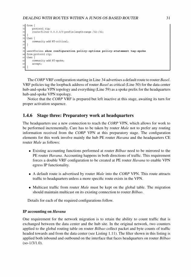
DEALING WITH ROUTES WITHIN A JUNOS OS BASED ROUTER 31
51 from {52 protocol rip;53 route-filter 0.0.0.0/0 prefix-length-range /32-/32;54 }55 then {56 community add RT-critical;57 }58
59 user@Torino> show configuration policy-options policy-statement tag-spoke60 from protocol rip;61 then {62 community add RT-spoke;63 accept;64 }
The CORP VRF configuration starting in Line 34 advertises a default route to router Basel.VRF policies tag the loopback address of router Basel as critical (Line 50) for the data centerhub-and-spoke VPN topology and everything (Line 59) as a spoke prefix for the headquartershub-and-spoke VPN topology.
Notice that the CORP VRF is prepared but left inactive at this stage, awaiting its turn forproper activation sequence.
1.4.6 Stage three: Preparatory work at headquarters
The headquarters use a new connection to reach the CORP VPN, which allows for work tobe performed incrementally. Care has to be taken by router Male not to prefer any routinginformation received from the CORP VPN at this preparatory stage. The configurationelements for this work involve mainly the hub PE router Havana and the headquarters CErouter Male as follows:
• Existing accounting functions performed at router Bilbao need to be mirrored to thePE router Havana. Accounting happens in both directions of traffic. This requirementforces a double VRF configuration to be created at PE router Havana to enable VPNegress IP functionality.
• A default route is advertised by router Male into the CORP VPN. This route attractstraffic to headquarters unless a more specific route exists in the VPN.
• Multicast traffic from router Male must be kept on the global table. The migrationshould maintain multicast on its existing connection to router Bilbao.
Details for each of the required configurations follow.
IP accounting on Havana
One requirement for the network migration is to retain the ability to count traffic that isexchanged between the data center and the hub site. In the original network, two countersapplied to the global routing table on router Bilbao collect packet and byte counts of trafficheaded towards and from the data center (see Listing 1.11). The filter shown in this listing isapplied both inbound and outbound on the interface that faces headquarters on router Bilbao(so-1/3/1.0).

32 NETWORK MERGERS AND MIGRATIONS
Listing 1.11: Data center traffic accounting at hub border
1 user@Bilbao-re0> show configuration firewall family inet2 filter count-DC-traffic {3 interface-specific;4 term from-DC {5 from {6 source-address {7 10.1.1.0/24;8 }9 }
10 then count from-DC;11 }12 term to-DC {13 from {14 destination-address {15 10.1.1.0/24;16 }17 }18 then count to-DC;19 }20 term default {21 then accept;22 }23 }
Junos Tip: Sharing IP filters across interfaces
In Junos OS, a filter applied to different units on the same physical interface is shared,with one instance of each of the memory elements (counter, policer). This featureis leveraged in this case study to apply the same filter to two directions of traffic,for each direction incrementing the counter in the respective term. By enabling theinterface-specific configuration statement, the filter is automatically split and theinterface name and traffic direction (i for input and o for output) are appended to the filtername in operational command output, as shown in Listing 1.12.
Listing 1.12: Sharing firewall filter across interfaces
1 user@Bilbao-re0> show firewall2
3 Filter: count-DC-traffic-so-1/3/1.0-i # Input direction4 Counters:5 Name Bytes Packets6 from-DC-so-1/3/1.0-i 0 07 to-DC-so-1/3/1.0-i 0 08 Filter: count-DC-traffic-so-1/3/1.0-o # Output direction9 Counters:
10 Name Bytes Packets11 from-DC-so-1/3/1.0-o 0 012 to-DC-so-1/3/1.0-o 0 0
Applying the filter on the hub PE works only in the inbound direction by default; traffic inthe reverse direction, from the core to the access, is switched by MPLS at the PE and is notprocessed by IP filters.
Enabling egress IP functionality through the vrf-table-label knob, associates asingle MPLS table label with the whole VRF and prepares the hardware to perform an IPlookup on MPLS-tagged traffic arriving with that label. This topic is discussed at length inSection 5.4.1.

DEALING WITH ROUTES WITHIN A JUNOS OS BASED ROUTER 33
A regular hub-and-spoke PE configuration in which the hub site advertises a default route,as in this case, can generally be implemented with a single VRF and proper tagging ofcommunities, such as the setup carried out in the data center PE router Livorno. However, ifIP features are enabled at the hub, an IP lookup inside the VRF finds the spoke destinationsand spoke-to-spoke traffic bypasses the hub site completely.
To avoid a traffic loop at the hub PE router Havana, a second VRF is required to splitthe two directions of traffic flow. Effectively, each VRF is used in one direction of traffic,although both VRFs share a single PE–CE interface.
Listing 1.13 shows the required configuration. Notice in Line 25 that an additional RDis allocated, because having the same RD on two VRFs of the same PE is not allowedin Junos OS. The hub-and-spoke configuration is split between two VRFs, CORP-Huband CORP-Hub-Downstream routing instances, and IP features are enabled at Line 28.Notice that the interface is present only in CORP-Hub. The second VRF receives allroutes from the first through the auto-export mechanism. Line 10 leaks the hub routesfrom CORP-Hub into CORP-Hub-Downstream, which accepts them on Line 30. Theno-vrf-advertise configuration on Line 8 blocks advertisement of routes learned fromthe hub site and delegates this task to CORP-Hub-Downstream, which attracts traffic andperform IP functions because of the vrf-table-label knob shown on Line 28.
Listing 1.13: IP features at the hub PE router Havana requires two VRFs
1 user@Havana> show configuration routing-instances2 CORP-Hub {3 instance-type vrf;4 interface ge-1/1/0.0;5 route-distinguisher 64500:1;6 vrf-import [ from-spoke from-datacenter ];7 vrf-export tag-hub;8 no-vrf-advertise; # Refrain from advertising local routes in BGP9 routing-options {
10 auto-export; # Export local routes to Hub-Downstream VRF11 }12 protocols {13 bgp {14 group hub { # EBGP to Hub router Male15 type external;16 export all;17 peer-as 65000;18 neighbor 10.255.100.85;19 }20 }21 }22 }23 CORP-Hub-Downstream {24 instance-type vrf;25 route-distinguisher 64500:2; # Additional RD26 vrf-import from-hub;27 vrf-export tag-hub;28 vrf-table-label; # Enable table-label for IP processing29 routing-options {30 auto-export; # Import local routes from Hub VRF31 }32 }
Establishing the default route on the hub PE Havana
Once the CORP VRF is configured in router Havana, activation of the VRF can take place byestablishing a connection of headquarters to PE router Havana. The configuration of router

34 NETWORK MERGERS AND MIGRATIONS
Male to support this new connection including the advertisement of a default route is shownin Listing 1.14. EBGP is used as the PE–CE protocol.
Listing 1.14: Male advertises a default to router Havana
1 user@male-re0> show configuration protocols bgp2 group ebgp {3 type external;4 export default;5 neighbor 10.255.100.86 {6 peer-as 64500;7 }8 }9
10 user@male-re0> show configuration policy-options policy-statement default11 from {12 route-filter 0.0.0.0/0 exact;13 }14 then accept;
Listing 1.15 shows the result of configuration changes in router Male, in which routerHavana receives from the headquarters router Male only a default route, which is sent overEBGP. The other prefixes in the CORP VRF represent connections via local interfaces.
Listing 1.15: Hub PE CORP VRF including the downstream VRF with hub default
1 user@Havana> show route table CORP terse 0/0 exact2
3 CORP-Hub.inet.0: 9 destinations, 9 routes (9 active, 0 holddown, 0 hidden)4 + = Active Route, - = Last Active, * = Both5
6 A Destination P Prf Metric 1 Metric 2 Next hop AS path7 * 0.0.0.0/0 B 170 100 >10.255.100.85 65000 I8
9 CORP-Hub-Downstream.inet.0: 1 destinations, 1 routes (1 active, 0 holddown, 0 hidden)10 + = Active Route, - = Last Active, * = Both11
12 A Destination P Prf Metric 1 Metric 2 Next hop AS path13 * 0.0.0.0/0 B 170 100 >10.255.100.85 65000 I
The no-vrf-advertise statement in Line 8 of the CORP-hub configuration shownin Listing 1.13 suppresses advertisement of the primary route, instead advertising the hubtagged, by default, with the CORP-hub-downstream table label, as shown in Listing 1.16Line 7. The RD in Line 6 also hints at the correct VRF. Note that the no-vrf-advertiseknob does not prevent the auto-export module from redistributing the routes locally.
Listing 1.16: Advertising hub default with a table label
1 user@Havana> show route advertising-protocol bgp 192.168.1.1 detail2
3 CORP-Hub-Downstream.inet.0: 1 destinations, 1 routes (1 active, 0 holddown, 0 hidden)4 * 0.0.0.0/0 (1 entry, 1 announced)5 BGP group IBGP-VPN type Internal6 Route Distinguisher: 64500:27 VPN Label: 168 Nexthop: Self9 Flags: Nexthop Change
10 Localpref: 10011 AS path: [64500] 65000 I12 Communities: target:64500:113
14 user@Havana> show route table mpls label 1615

DEALING WITH ROUTES WITHIN A JUNOS OS BASED ROUTER 35
16 mpls.0: 11 destinations, 11 routes (11 active, 0 holddown, 0 hidden)17 + = Active Route, - = Last Active, * = Both18
19 16 *[VPN/0] 1w0d 15:45:0420 to table CORP-Hub-Downstream.inet.0, Pop
This default route directs traffic from CORP VPN users, via the hub, to destinations in theglobal routing table or to destinations in other VPNs. Note that this default route is receivedby all members of the VPN, including the data center.
Maintain multicast away from CORP VPN
One of the migration challenges is to keep multicast traffic between the data center andthe headquarters in the global routing table, while directing all unicast flows between theheadquarters and the data center over the CORP VPN by default. Fortunately, PIM in JunosOS can be configured to use a restricted routing view that includes only certain routes. Theseroutes can be leaked through the RIB group mechanism in a RIB that PIM consults for themulticast RPF check.
The configuration for PIM at the onset of the migration is shown in Listing 1.17. Densegroups are defined for the auto-rp functionality on Line 7, which allows to discover theRendezvous point (RP) for the sparse mode multicast groups.
Listing 1.17: Original PIM configuration on router Male
1 pim {2 dense-groups {3 224.0.1.39/32;4 224.0.1.40/32;5 }6 rp {7 auto-rp discovery;8 }9 interface so-3/2/1.0 {
10 mode sparse-dense;11 }12 }
Using the RIB group construct, one additional table is built on router Male by redistribut-ing only selected information across the two RIBs. There is no need to create additionalinstances or RIBs. Two of the existing default RIBs in the master instance (Table 1.2) areleveraged, namely the unicast (inet.0) and multicast (inet.2) RIBs.
The Junos OS configuration for this setup can be seen in Listing 1.18. Two RIB groupdefinitions are required: leak-dc-to-inet2 (Line 2) distributes routes that pass the policydc-n-rp (Line 4); and pim-uses-inet2 (Line 6) is used to constrain the RPF view for thePIM protocol, containing just one RIB to override the default lookup in inet.0.
Listing 1.18: RIB groups configuration to provide incongruent unicast/multicast topologies
1 user@male-re1> show configuration routing-options rib-groups2 leak-dc-to-inet2 {3 import-rib [ inet.0 inet.2 ];4 import-policy dc-n-rp; # Data Center and Rendezvous Point prefixes5 }6 pim-uses-inet2 {7 import-rib inet.2;8 }

36 NETWORK MERGERS AND MIGRATIONS
The policy implemented in Listing 1.19 limits population of the inet.2 table to thoserelevant data center prefixes arriving from the global routing table. It is worth noting thatthe specific term filter-inet2 (Line 18) blocks additional routes from being leaked to inet.2.The default action in a rib-group policy is to accept; hence, there is no need for an additionalterm with an accept action for routes that have to populate inet.0 (Line 22).
Listing 1.19: Restricting route leak into inet.2 using policy language
1 user@male-re1> show configuration policy-options policy-statement dc-n-rp2 term DC-to-inet0 { # Accept datacenter prefixes3 from {4 interface so-3/2/1.0;5 route-filter 10.1.0.0/16 orlonger;6 }7 to rib inet.2; # Into inet.28 then accept;9 }
10 term RP { # Accept the Rendezvous Point (RP) prefix11 from {12 interface so-3/2/1.0;13 route-filter 192.168.1.8/32 exact;14 }15 to rib inet.2; # Into inet.216 then accept;17 }18 term filter-inet2 { # Block other to inet.219 to rib inet.2;20 then reject;21 }22 inactive: term default { # Default policy23 to rib inet.0;24 then accept;25 }
Additional configuration shown on Listing 1.20 binds the leak-dc-to-inet2 RIB group toRIP to leak received prefixes into the inet.2 table on Line 2. In addition, the pim-uses-inet2RIB group is bound to PIM on Line 9, to choose only routes in inet.2 for RPF check.
Listing 1.20: Binding RIB groups to protocols
1 user@male-re0> show configuration protocols rip2 rib-group leak-dc-to-inet2;3 group hub {4 export default;5 neighbor so-3/2/1.0;6 }7
8 user@male-re1> show configuration protocols pim rib-groups9 inet pim-uses-inet2;
The result of this configuration is shown in Listing 1.21. Notice that there is no differencein the routing information for both inet.0 and inet.2 tables because the data center prefix is onthe global routing table and no information is received from CORP VPN. Line 38 confirmsthat PIM is using inet.2 for its RPF check calculation.
Listing 1.21: Leaked routes in inet.2
1 user@male-re0> show route 10.1.1/242
3 inet.0: 19 destinations, 20 routes (19 active, 0 holddown, 0 hidden)4 + = Active Route, - = Last Active, * = Both

DEALING WITH ROUTES WITHIN A JUNOS OS BASED ROUTER 37
5
6 10.1.1.0/24 *[RIP/100] 01:05:32, metric 2, tag 17 > to 10.255.100.78 via so-3/2/1.08 10.1.1.21/32 *[RIP/100] 01:05:32, metric 2, tag 09 > to 10.255.100.78 via so-3/2/1.0
10 10.1.1.88/30 *[RIP/100] 01:05:32, metric 2, tag 011 > to 10.255.100.78 via so-3/2/1.012
13 inet.2: 4 destinations, 4 routes (4 active, 0 holddown, 0 hidden)14 + = Active Route, - = Last Active, * = Both15
16 10.1.1.0/24 *[RIP/100] 00:00:14, metric 2, tag 117 > to 10.255.100.78 via so-3/2/1.018 10.1.1.21/32 *[RIP/100] 00:00:14, metric 2, tag 019 > to 10.255.100.78 via so-3/2/1.020 10.1.1.88/30 *[RIP/100] 00:00:14, metric 2, tag 021 > to 10.255.100.78 via so-3/2/1.022
23 user@male-re0> show route 192.168.1.8/3224
25 inet.0: 19 destinations, 20 routes (19 active, 0 holddown, 0 hidden)26 + = Active Route, - = Last Active, * = Both27
28 192.168.1.8/32 *[RIP/100] 02:44:25, metric 2, tag 029 > to 10.255.100.78 via so-3/2/1.030
31 inet.2: 4 destinations, 4 routes (4 active, 0 holddown, 0 hidden)32 + = Active Route, - = Last Active, * = Both33
34 192.168.1.8/32 *[RIP/100] 00:00:22, metric 2, tag 035 > to 10.255.100.78 via so-3/2/1.036
37 user@male-re0> show multicast rpf38 Multicast RPF table: inet.2 , 4 entries39
40 10.1.1.0/2441 Protocol: RIP42 Interface: so-3/2/1.043 Neighbor: 10.255.100.7844
45 10.1.1.21/3246 Protocol: RIP47 Interface: so-3/2/1.048 Neighbor: 10.255.100.7849
50 10.1.1.88/3051 Protocol: RIP52 Interface: so-3/2/1.053 Neighbor: 10.255.100.7854
55 192.168.1.8/3256 Protocol: RIP57 Interface: so-3/2/1.058 Neighbor: 10.255.100.78
Verification of the implemented changes to separate multicast traffic from the CORP VRFis discussed in Section 1.4.8.
1.4.7 Stage four: Preparatory work at the data center
Lack of a separate interconnect from the data center to the CORP VPN introduces additionalcomplexity because a single access interface shares traffic for both the global routing tableand the VPN. During the migration process, the data center access interface has to be

38 NETWORK MERGERS AND MIGRATIONS
homed to both the global routing table and the CORP VRF to serve all spoke sites withno intervention from headquarters.
No changes are required in the configuration of the data denter router Honolulu becausethe data center is unaware of the changes to become part of a VPN. Preparatory steps at thedata center PE router Livorno follow:
• configuration for router Livorno as data center PE with single attachment;
• access from all user sites to the data center;
• access from the data center to reach both migrated and non-migrated user sites.
Data center PE configuration
The initial configuration on the PE router Livorno related to the protocols on the globalrouting table is shown in Listing 1.22. Besides the backbone OSPF area (Line 15), routerLivorno acts as ABR for the data center, sited in NSSA area 1 (Line 24). The access to routerBarcelona using RIP routing is configured in Line 34.
Listing 1.22: Router Livorno initial protocol configuration
1 user@Livorno> show configuration protocols2 mpls { # MPLS core interfaces3 <...>4 }5 bgp { # L3VPN BGP session to the reflector Nantes6 group IBGP-VPN {7 type internal;8 local-address 192.168.1.6;9 family inet-vpn {
10 unicast;11 }12 neighbor 192.168.1.1;13 }14 }15 ospf {16 area 0.0.0.0 { # Backbone OSPF17 interface fxp0.0 {18 disable;19 }20 interface so-0/0/0.0;21 interface so-0/0/1.0;22 interface lo0.0;23 }24 area 0.0.0.1 { # Data Center NSSA Area 125 nssa {26 default-lsa default-metric 1;27 no-summaries;28 }29 interface ge-1/3/0.0;30 }31 }32 ldp { # LDP for MPLS transport tunnels33 <...>34 rip { # RIP to site Barcelona35 group BCN {36 export default;37 neighbor ge-0/2/0.0;38 }39 }

DEALING WITH ROUTES WITHIN A JUNOS OS BASED ROUTER 39
Listing 1.23 provides the preliminary configuration of router Livorno with the globalrouting table protocols and a newly instantiated CORP VRF. The data center PE routerLivorno also homes regular spoke sites like router Barcelona, which is reflected in theconfiguration by having a mixed RT vrf-import (Line 9) and vrf-export (Line 10)policy and additional RIP protocol configuration for the spoke interface (Line 33).
Listing 1.23: Interim configuration for CORP VRF in data center PE router Livorno
1 user@Livorno# show routing-instances CORP2 ##3 ## inactive: routing-instances4 ##5 instance-type vrf;6 interface ge-1/3/0.0;7 interface ge-0/2/0.0;8 route-distinguisher 64500:1;9 vrf-import [ from-critical from-hub ];
10 vrf-export [ tag-datacenter tag-spoke ];11 routing-options {12 inactive: interface-routes {13 rib-group inet leak-to-inet0;14 }15 inactive: auto-export {16 family inet {17 unicast {18 inactive: rib-group leak-to-inet0;19 }20 }21 }22 }23 protocols {24 inactive: ospf {25 area 0.0.0.1 {26 nssa {27 default-lsa default-metric 1;28 no-summaries;29 }30 interface ge-1/3/0.0;31 }32 }33 inactive: rip {34 group BCN {35 export default;36 neighbor ge-0/2/0.0;37 }38 }39 }
Notice the inactive: statement for the VRF as a whole, as well as in Line 12, Line 15, andLine 18. These portions of the configuration will be activated in following stages to illustratethe impact in populating the routing table.
The RIB group reference in Line 18 of Listing 1.23 corresponds to the configurationin Listing 1.24 that includes a policy to leak only the data center interface, but not otherinterfaces belonging to spoke sites connected on the same PE. Note that the default action forthe RIB group policy is to accept all routes. Hence, the CORP VRF is populated correctlywithout requiring a specific term in the policy that accepts routes in order to leak them intoCORP.inet.0.
Listing 1.24: Interface leaking rib-group configuration
1 [edit]2 user@Livorno# show routing-options rib-groups

40 NETWORK MERGERS AND MIGRATIONS
3 leak-to-inet0 {4 import-rib [ CORP.inet.0 inet.0 ];5 import-policy only-datacenter-interface;6 }7 [edit policy-options]8 user@Livorno# show policy-statement only-datacenter-interface9 term datacenter {
10 from interface ge-1/3/0.0;11 to rib inet.0;12 then accept;13 }14 term other {15 to rib inet.0;16 then reject;17 }
Access from data center to reach both migrated and non-migrated user sites
Once the migration is finished, the data center router Honolulu is unaware of the migrationthat took place at the PE, except for the reduced network visibility of prefixes from the globalrouting table that have been replaced by a default route pointing towards the headquarterssite.
To reach both migrated and non-migrated sites during the migration, router Livorno shouldfirst verify whether the destination of traffic coming from the data center is one of the alreadymigrated sites. If this is not the case, router Livorno should jump to the global routing tableinstead of following the headquarter’s default inside the CORP VRF.
Using a static default route on the CORP VRF that points to inet.0 would hide the existenceof the hub default route learned from router Havana inside the CORP VRF. Traffic from thedata center to non-migrated sites would effectively be directed always to the global routingtable. Notice that ignoring the hub default route would also affect traffic coming from otheralready migrated spokes on this PE, such as router Barcelona.
Therefore, a helper VRF construct is created that is used only for traffic coming fromthe data center. Its main goal is to provide access to migrated sites and to switch to theglobal routing table for non-migrated sites. Listing 1.25 shows the required configuration.Figure 1.14 is a graphical view of the proposed solution. Effectively, the data center VRF isused for the reverse direction (traffic from the remote sites towards the data center), while thehelper VRF has a constrained routing view that substitutes the headquarters default route fora local bypass. The helper VRF is used only for traffic from the data center to remote sites.
Listing 1.25: The helper VRF
1 routing-instances helper {2 instance-type vrf;3 route-distinguisher 64500:11;4 vrf-import from-critical;5 vrf-export null;6 routing-options {7 static {8 route 0.0.0.0/0 next-table inet.0;9 }
10 }11 }
Incoming traffic from the datacenter is redirected to use the helper VRF for the durationof the migration of the remote sites. The input firewall filter is attached to the data center

DEALING WITH ROUTES WITHIN A JUNOS OS BASED ROUTER 41
Hub&SpokeMPLS L3VPN
PE1 PE2 PE20
PEHub
Data Center PE
DataCenter
HeadQuarters
Keep Datacenter presence in global table
Direct connectivity to pre−migrated users
Datacenter presence in CORP VPN
Direct connectivity to migrated users
Keep HQ−Datacenter multicast on global
Transient connectivity
CORP.inet.0helper.inet.0
0/0 to inet.0 0/0 to HQ
0/0 to HQ
migrated sitesmigrated sites
pre
−m
igra
ted
sit
es
inet.0 CORPhelper
derive incoming
traffic to helper VRF
other migrated users
also connected to PE
Figure 1.14: Data center PE transition configuration.
interface as shown in Listing 1.26. Care has to be taken to keep the routing protocol traffichomed to the CORP VRF, in which the OSPF task is processing updates.
Listing 1.26: Diverting datacenter traffic to the helper VRF
1 user@Livorno> show configuration firewall family inet filter redirect-to-helper2 term ospf { # Leave control traffic on CORP3 from {4 protocol ospf;5 }6 then accept;7 }8 term traffic { # Other traffic to jump over to helper9 then {
10 routing-instance helper;11 }12 }13
14 user@Livorno> show configuration interfaces ge-1/3/015 description To_Honolulu_ge-5/2/0;16 unit 0 {17 family inet {18 inactive: filter {19 input redirect-to-helper;20 }21 address 10.1.1.89/30;22 }23 }
Notice that by configuring the filter only on the PE–CE interface to router Honolulu, thishelper VRF does not participate in traffic from other CORP VRF sites attached to routerLivorno such as router Barcelona. Hence, traffic from spoke sites attached to the CORP VRFfor other sites does not switch back to the global routing table and follows the default routein CORP VRF directed to headquarters.

42 NETWORK MERGERS AND MIGRATIONS
Maintaining access from all user sites to the data center
After the data center interface moves, data center visibility must be maintained simultane-ously on both the CORP VPN and the global table for the duration of the migration. Routinginformation that must be duplicated is both the local interface and the data center addressinglearned from OSPF.
Using RIB groups on the PE–CE side as configured in Listing 1.23 on Page 39 offers aperfect solution for this need. As seen in Line 12, it is ensured that the interface is visible inboth the CORP VRF and in the global routing table. The activation of the auto-export featurewith rib-groups (Line 15 and Line 18) triggers leaking of the data center prefixes towards themain table inet.0. More details of the activation are discussed in Section 1.4.8.
Redistribute OSPF area 1 into OSPF backbone
Although the leaking configuration effectively installs the data center OSPF routes intothe main table, the OSPF task running on the main instance considers these routes as notbelonging to its own task and does not incorporate them into its link-state database bydefault; that is, these routes are of protocol OSPF, but router Livorno is not an ABR afterthe interface move. The behavior differs from that of the old network, in which the Area 1NSSA Type 7 LSAs were automatically translated into Type 5 LSAs as part of the ABRfunction from [RFC2328].
Listing 1.27 shows the additional configuration required to export the data center routespresent in the main instance so as to propagate them into the OSPF core.
Listing 1.27: Exporting data center OSPF routes to backbone OSPF
1 user@Livorno> show configuration protocols ospf | compare rollback 12 + export datacenter; # Required to inject datacenter OSPF routes3 user@Livorno> show configuration policy-options policy-statement datacenter4 from {5 inactive: protocol ospf;6 interface ge-1/3/0.0;7 }8 then {9 tag 1000;
10 accept;11 }
1.4.8 Stage five: Move of data center site to CORP VRF
Moving the data center interface into the CORP VFR provides direct access from the datacenter to already migrated sites. The data center receives a default route from the hub,which is sufficient to reach the CORP VRF at router Livorno. The CORP VRF at routerLivorno contains more specific information that is learned from other PEs advertising routinginformation that belong to critical prefixes at spoke sites.
Note Before performing this step, to avoid breaking the multicast replication flows betweenthe hub and the data center, preparatory work at the hub CE router Male has separated theunicast and multicast RIBs, as discussed in Section 1.4.6.
The most critical stage in this migration is the move of the PE–CE interface of the datacenter. All destinations must keep connectivity to the data center in both directions (from

DEALING WITH ROUTES WITHIN A JUNOS OS BASED ROUTER 43
and to the data center). In addition, for critical destinations this connectivity has to be onthe shortest path. Heavy preparatory work in previous stages ensures that everything occurssmoothly.
Keeping traffic from the data center on global routing table
Despite the PE–CE interface change, traffic coming from the data center router Honolulushould stay on the global routing table at this stage. It is required to activate the firewall filterconfigured in Section 1.4.7 Listing 1.26 on Page 41 as shown in Listing 1.28 on Line 6 toensure that traffic does not travel inside the CORP VPN for non-migrated sites.
Listing 1.28: Deriving incoming traffic from the data center to the helper VRF
1 [edit]2 user@Livorno# show interfaces ge-1/3/03 description To_Honolulu_ge-5/2/0;4 unit 0 {5 family inet {6 inactive: filter { # Derive incoming traffic to helper VRF7 input redirect-to-helper;8 }9 address 10.1.1.89/30;
10 }11 }12 [edit]13 user@Livorno# activate interfaces ge-1/3/0 unit 0 family inet filter
Moving the interface to CORP VRF
Junos OS protocols perform validation check for interfaces assigned to them. The interfacehas to be present in the instance where the protocol is running. Because an interface cannotbe included in more than one instance, the PE–CE interface for the data center routerHonolulu must be deactivated in the main instance’s protocols, as shown in Listing 1.29,before enabling the CORP instance.
Listing 1.29: Moving PE–CE interfaces on router Livorno
1 user@Livorno# deactivate protocols ospf area 1 # datacenter OSPF2 user@Livorno# activate routing-instances3 user@Livorno# activate routing-instances CORP protocols ospf4 user@Livorno# commit5 commit complete
The ability of Junos OS to group changes into a single commit operation optimizesdowntime during change scenarios. Not all required configuration has been activated at thisstage. The configuration commit action shown on Line 4 can be deferred until other inactivegroups from the configuration are activated, as discussed henceforth. The intermediateconfiguration change has been activated for illustration purposes.
Verification of traffic from the data center
A trace route from data center router Honolulu to router Basel is shown in Listing 1.30. Asexpected, traffic follows the global routing table bypassing the hub site.

44 NETWORK MERGERS AND MIGRATIONS
Listing 1.30: Traffic from router Honolulu to router Basel
1 user@honolulu-re0> traceroute 10.100.1.10 source 10.1.1.212 traceroute to 10.100.1.10 (10.100.1.10) from 10.1.1.21, 30 hops max, 40 byte packets3 1 livorno-ge1300 (10.1.1.89) 0.499 ms 0.417 ms 0.402 ms4 2 skopie-so1000 (172.16.1.33) 0.511 ms 0.462 ms 0.472 ms5 3 nantes-so0100 (172.16.1.1) 0.521 ms 0.461 ms 0.469 ms6 4 torino-so0100 (172.16.1.97) 0.571 ms 0.488 ms 0.491 ms7 5 basel (10.100.1.10) 1.500 ms 1.383 ms 1.579 ms
What If... Data center traffic bypassing the helper table
Listing 1.31 illustrates how traffic entering the PE–CE interface from the data center that isnot derived to the helper VRF with a firewall filter (Line 1) follows the default route insidethe CORP VRF (Line 8). The trace route on Line 12 confirms that traffic is taking a detourover router Male, which is undesired.
Listing 1.31: Traffic from router Honolulu to router Basel
1 user@Livorno# deactivate interfaces ge-1/3/0 unit 0 family inet filter input2
3 user@Livorno> show route table CORP 10.100.1.104
5 CORP.inet.0: 11 destinations, 11 routes (11 active, 0 holddown, 0 hidden)6 + = Active Route, - = Last Active, * = Both7
8 0.0.0.0/0 *[BGP/170] 00:00:37, localpref 100, from 192.168.1.19 AS path: 65000 I
10 > via so-0/0/1.0, Push 30150411
12 user@honolulu-re0> traceroute 10.100.1.10 source 10.1.1.2113 traceroute to 10.100.1.10 (10.100.1.10) from 10.1.1.21, 30 hops max, 40 byte packets14 1 livorno-ge1300 (10.1.1.89) 0.496 ms 0.419 ms 0.399 ms15 2 havana-so1000 (172.16.1.37) 0.721 ms 0.594 ms 0.589 ms16 MPLS Label=301504 CoS=0 TTL=1 S=117 3 male-ge4240 (10.255.100.85) 0.369 ms 0.311 ms 0.311 ms18 4 bilbao-so1310 (10.255.100.78) 0.503 ms 0.519 ms 0.483 ms19 5 torino-at0010 (172.16.1.101) 0.649 ms 0.881 ms 1.004 ms20 6 basel (10.100.1.10) 1.770 ms 1.467 ms 1.493 ms
The current CORP VRF configuration (still containing inactive statements for the leakingconfiguration) yields a routing table with data center prefixes as shown in Listing 1.32. Noticethat by moving the PE–CE interface, the data center prefixes are not available on the globaltable anymore.
Listing 1.32: Data center address space after moving the PE–CE interface
1 user@Livorno> show route 10.1/16 terse2
3 CORP.inet.0: 12 destinations, 12 routes (12 active, 0 holddown, 0 hidden)4 + = Active Route, - = Last Active, * = Both5
6 A Destination P Prf Metric 1 Metric 2 Next hop AS path7 * 10.1.1.0/24 O 150 0 >10.1.1.908 * 10.1.1.21/32 O 150 0 >10.1.1.909 * 10.1.1.88/30 D 0 >ge-1/3/0.0
10 * 10.1.1.89/32 L 0 Local
Listing 1.33 shows the address space of the data center at the data center PE router Livornoafter enabling the RIB group configuration for the data center interface.

DEALING WITH ROUTES WITHIN A JUNOS OS BASED ROUTER 45
Listing 1.33: Activating interface leaking
1 user@Livorno# activate routing-instances CORP routing-options interface-routes2 [edit]3 user@Livorno# commit and-quit4 commit complete5 Exiting configuration mode6
7 user@Livorno> show route 10.1/16 terse8
9 inet.0: 40 destinations, 42 routes (39 active, 0 holddown, 1 hidden)10 + = Active Route, - = Last Active, * = Both11
12 A Destination P Prf Metric 1 Metric 2 Next hop AS path13 * 10.1.1.88/30 D 0 >ge-1/3/0.014
15 CORP.inet.0: 11 destinations, 11 routes (11 active, 0 holddown, 0 hidden)16 + = Active Route, - = Last Active, * = Both17
18 A Destination P Prf Metric 1 Metric 2 Next hop AS path19 * 10.1.1.0/24 O 150 0 >10.1.1.9020 * 10.1.1.21/32 O 150 0 >10.1.1.9021 * 10.1.1.88/30 D 0 >ge-1/3/0.022 * 10.1.1.89/32 L 0 Local
Activation of the auto-export feature with RIB groups (Listing 1.23, Line 15 and Line 18)triggers leaking of the data center prefixes towards the main table inet.0, as shown inListing 1.34.
Listing 1.34: Leaking data-center OSPF routes to inet.0
1 [edit routing-instances CORP routing-options]2 user@Livorno# activate auto-export3 user@Livorno# activate auto-export family inet unicast rib-group4 user@Livorno> show route 10.1/16 terse5
6 inet.0: 43 destinations, 45 routes (42 active, 0 holddown, 1 hidden)7 + = Active Route, - = Last Active, * = Both8
9 A Destination P Prf Metric 1 Metric 2 Next hop AS path10 * 10.1.1.0/24 O 150 0 >10.1.1.9011 * 10.1.1.21/32 O 150 0 >10.1.1.9012 * 10.1.1.88/30 D 0 >ge-1/3/0.013
14 CORP.inet.0: 12 destinations, 12 routes (12 active, 0 holddown, 0 hidden)15 + = Active Route, - = Last Active, * = Both16
17 A Destination P Prf Metric 1 Metric 2 Next hop AS path18 * 10.1.1.0/24 O 150 0 >10.1.1.9019 * 10.1.1.21/32 O 150 0 >10.1.1.9020 * 10.1.1.88/30 D 0 >ge-1/3/0.021 * 10.1.1.89/32 L 0 Local
Listing 1.35 shows the resulting data center OSPF route leaked to the inet.0 in the maininstance after the previous configuration has been applied. The announcement bit on Line 12indicates that the OSPF task in the main instance is interested in changes for this prefix.The OSPF database in the main instance shows the prefix as a Type 5 AS External LSAstarting at Line 31.
Listing 1.35: Notification between OSPF tasks
1 user@Livorno> show route 10.1.1/24 exact detail table inet.02
3 inet.0: 43 destinations, 45 routes (42 active, 0 holddown, 1 hidden)
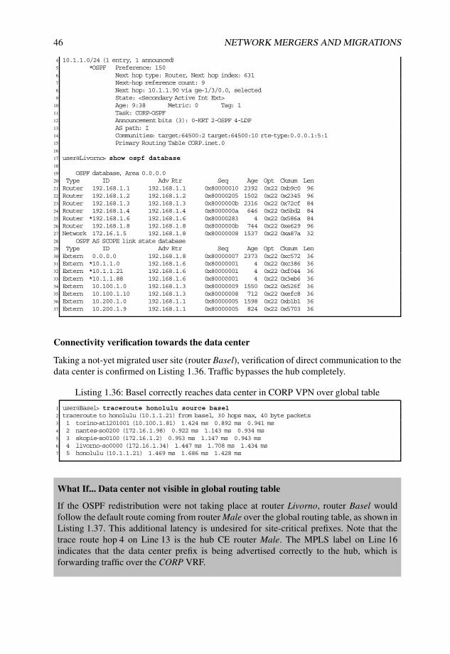
46 NETWORK MERGERS AND MIGRATIONS
4 10.1.1.0/24 (1 entry, 1 announced)5 *OSPF Preference: 1506 Next hop type: Router, Next hop index: 6317 Next-hop reference count: 98 Next hop: 10.1.1.90 via ge-1/3/0.0, selected9 State: <Secondary Active Int Ext>
10 Age: 9:38 Metric: 0 Tag: 111 Task: CORP-OSPF12 Announcement bits (3): 0-KRT 2-OSPF 4-LDP13 AS path: I14 Communities: target:64500:2 target:64500:10 rte-type:0.0.0.1:5:115 Primary Routing Table CORP.inet.016
17 user@Livorno> show ospf database18
19 OSPF database, Area 0.0.0.020 Type ID Adv Rtr Seq Age Opt Cksum Len21 Router 192.168.1.1 192.168.1.1 0x80000010 2392 0x22 0xb9c0 9622 Router 192.168.1.2 192.168.1.2 0x80000205 1502 0x22 0x2345 9623 Router 192.168.1.3 192.168.1.3 0x8000000b 2316 0x22 0x72cf 8424 Router 192.168.1.4 192.168.1.4 0x8000000a 646 0x22 0x5bd2 8425 Router *192.168.1.6 192.168.1.6 0x80000283 4 0x22 0x586a 8426 Router 192.168.1.8 192.168.1.8 0x8000000b 744 0x22 0xe629 9627 Network 172.16.1.5 192.168.1.8 0x80000008 1537 0x22 0xa87a 3228 OSPF AS SCOPE link state database29 Type ID Adv Rtr Seq Age Opt Cksum Len30 Extern 0.0.0.0 192.168.1.8 0x80000007 2373 0x22 0xc572 3631 Extern *10.1.1.0 192.168.1.6 0x80000001 4 0x22 0xc386 3632 Extern *10.1.1.21 192.168.1.6 0x80000001 4 0x22 0xf044 3633 Extern *10.1.1.88 192.168.1.6 0x80000001 4 0x22 0x3eb6 3634 Extern 10.100.1.0 192.168.1.3 0x80000009 1550 0x22 0x526f 3635 Extern 10.100.1.10 192.168.1.3 0x80000008 712 0x22 0xefc8 3636 Extern 10.200.1.0 192.168.1.1 0x80000005 1598 0x22 0xb1b1 3637 Extern 10.200.1.9 192.168.1.1 0x80000005 824 0x22 0x5703 36
Connectivity verification towards the data center
Taking a not-yet migrated user site (router Basel), verification of direct communication to thedata center is confirmed on Listing 1.36. Traffic bypasses the hub completely.
Listing 1.36: Basel correctly reaches data center in CORP VPN over global table
1 user@Basel> traceroute honolulu source basel2 traceroute to honolulu (10.1.1.21) from basel, 30 hops max, 40 byte packets3 1 torino-at1201001 (10.100.1.81) 1.424 ms 0.892 ms 0.941 ms4 2 nantes-so0200 (172.16.1.98) 0.922 ms 1.143 ms 0.934 ms5 3 skopie-so0100 (172.16.1.2) 0.953 ms 1.147 ms 0.943 ms6 4 livorno-so0000 (172.16.1.34) 1.447 ms 1.708 ms 1.434 ms7 5 honolulu (10.1.1.21) 1.469 ms 1.686 ms 1.428 ms
What If... Data center not visible in global routing table
If the OSPF redistribution were not taking place at router Livorno, router Basel wouldfollow the default route coming from router Male over the global routing table, as shown inListing 1.37. This additional latency is undesired for site-critical prefixes. Note that thetrace route hop 4 on Line 13 is the hub CE router Male. The MPLS label on Line 16indicates that the data center prefix is being advertised correctly to the hub, which isforwarding traffic over the CORP VRF.

DEALING WITH ROUTES WITHIN A JUNOS OS BASED ROUTER 47
Listing 1.37: With no OSPF redistribution, Basel follows the corporate default route
1 user@Livorno# deactivate protocols ospf export2
3 [edit]4 user@Livorno# commit and-quit5 commit complete6 Exiting configuration mode7
8 user@Basel> traceroute honolulu source basel9 traceroute to honolulu (10.1.1.21) from basel, 30 hops max, 40 byte packets
10 1 torino-at1201001 (10.100.1.81) 1.305 ms 0.899 ms 0.926 ms11 2 nantes-so0200 (172.16.1.98) 0.933 ms 1.137 ms 0.929 ms12 3 bilbao-ge0100 (172.16.1.5) 1.439 ms 1.741 ms 1.436 ms13 4 male-so3210 (10.255.100.77) 0.944 ms 1.151 ms 0.936 ms14 5 havana-ge1100 (10.255.100.86) 1.449 ms 1.714 ms 1.439 ms15 6 livorno-so0010 (172.16.1.38) 1.288 ms 1.028 ms 1.428 ms16 MPLS Label=300640 CoS=0 TTL=1 S=117 7 honolulu (10.1.1.21) 1.702 ms 1.709 ms 1.436 ms
Confirming multicast stays on global routing table
A key requirement of the migration is to maintain multicast on the global routing table. Thedata center prefix is propagated within the CORP VPN and eventually reaches the hub CErouter Male in which the special preparatory work carried out for multicast in Section 1.4.5prevents the use of the CORP VRF.
The data center prefix on router Male as seen in Listing 1.38 shows that the multicast RPFRIB contains only one RIP route coming from neighbor router Bilbao, while the unicast RIBinet.0 holds both the BGP route from router Havana (over CORP VPN) and the RIP routefrom router Bilbao. The RIP route has been configured with a worse preference (180) inorder that unicast traffic flows over the CORP VPN, if the destination is available. Becausethe inet.2 table has no BGP route, the RIP route is used, regardless of its preference. Thisscheme allows migrated user sites to use the CORP VPN in both directions, while keepingmulticast traffic on the global table.
Listing 1.38: Incongruent routing tables for unicast/multicast
1 user@male-re0> show route 10.1.1.0/24 terse2
3 inet.0: 20 destinations, 23 routes (20 active, 0 holddown, 0 hidden)4 + = Active Route, - = Last Active, * = Both5
6 A Destination P Prf Metric 1 Metric 2 Next hop AS path7 * 10.1.1.0/24 B 170 100 >10.255.100.86 64500 I # BGP route8 R 180 2 >10.255.100.78 # RIP route9 * 10.1.1.21/32 B 170 100 >10.255.100.86 64500 I # BGP route
10 R 180 2 >10.255.100.78 # RIP route11
12 inet.2: 3 destinations, 3 routes (3 active, 0 holddown, 0 hidden)13 + = Active Route, - = Last Active, * = Both14
15 A Destination P Prf Metric 1 Metric 2 Next hop AS path16 * 10.1.1.0/24 R 180 2 >10.255.100.7817 * 10.1.1.21/32 R 180 2 >10.255.100.7818
19 user@male-re0> show multicast rpf | match inet.220 Multicast RPF table: inet.2 , 4 entries
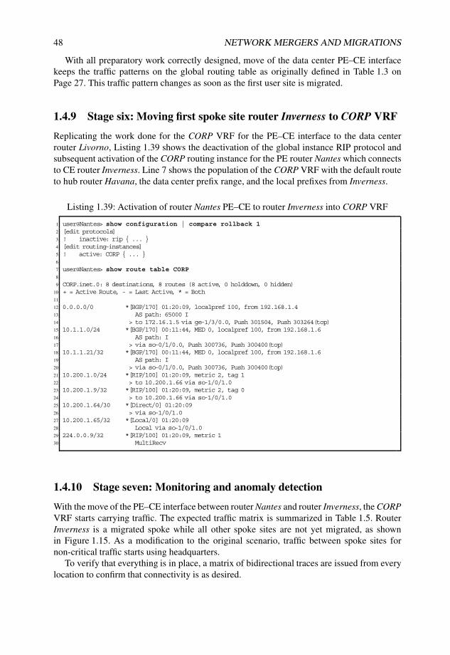
48 NETWORK MERGERS AND MIGRATIONS
With all preparatory work correctly designed, move of the data center PE–CE interfacekeeps the traffic patterns on the global routing table as originally defined in Table 1.3 onPage 27. This traffic pattern changes as soon as the first user site is migrated.
1.4.9 Stage six: Moving first spoke site router Inverness to CORP VRF
Replicating the work done for the CORP VRF for the PE–CE interface to the data centerrouter Livorno, Listing 1.39 shows the deactivation of the global instance RIP protocol andsubsequent activation of the CORP routing instance for the PE router Nantes which connectsto CE router Inverness. Line 7 shows the population of the CORP VRF with the default routeto hub router Havana, the data center prefix range, and the local prefixes from Inverness.
Listing 1.39: Activation of router Nantes PE–CE to router Inverness into CORP VRF
1 user@Nantes> show configuration | compare rollback 12 [edit protocols]3 ! inactive: rip { ... }4 [edit routing-instances]5 ! active: CORP { ... }6
7 user@Nantes> show route table CORP8
9 CORP.inet.0: 8 destinations, 8 routes (8 active, 0 holddown, 0 hidden)10 + = Active Route, - = Last Active, * = Both11
12 0.0.0.0/0 *[BGP/170] 01:20:09, localpref 100, from 192.168.1.413 AS path: 65000 I14 > to 172.16.1.5 via ge-1/3/0.0, Push 301504, Push 303264(top)15 10.1.1.0/24 *[BGP/170] 00:11:44, MED 0, localpref 100, from 192.168.1.616 AS path: I17 > via so-0/1/0.0, Push 300736, Push 300400(top)18 10.1.1.21/32 *[BGP/170] 00:11:44, MED 0, localpref 100, from 192.168.1.619 AS path: I20 > via so-0/1/0.0, Push 300736, Push 300400(top)21 10.200.1.0/24 *[RIP/100] 01:20:09, metric 2, tag 122 > to 10.200.1.66 via so-1/0/1.023 10.200.1.9/32 *[RIP/100] 01:20:09, metric 2, tag 024 > to 10.200.1.66 via so-1/0/1.025 10.200.1.64/30 *[Direct/0] 01:20:0926 > via so-1/0/1.027 10.200.1.65/32 *[Local/0] 01:20:0928 Local via so-1/0/1.029 224.0.0.9/32 *[RIP/100] 01:20:09, metric 130 MultiRecv
1.4.10 Stage seven: Monitoring and anomaly detection
With the move of the PE–CE interface between router Nantes and router Inverness, the CORPVRF starts carrying traffic. The expected traffic matrix is summarized in Table 1.5. RouterInverness is a migrated spoke while all other spoke sites are not yet migrated, as shownin Figure 1.15. As a modification to the original scenario, traffic between spoke sites fornon-critical traffic starts using headquarters.
To verify that everything is in place, a matrix of bidirectional traces are issued from everylocation to confirm that connectivity is as desired.

DEALING WITH ROUTES WITHIN A JUNOS OS BASED ROUTER 49
Table 1.5 Traffic flow matrix halfway through the migration
HQ DC NMS MS
Headquarters (HQ) Global Global CORPData Center (DC) Global Global CORPNon-Migrated Spoke (NMS) Global Global Global HubMigrated Spoke (MS) CORP CORP Hub CORP/hub
Connectivity between migrated spokes uses the CORP VRF via the hub.
Male
Bilbao
Havana
Nantes
Skopie
Livorno
Barcelona
Honolulu
192.168.1.4
10.255.100.20
192.168.1.8
192.168.1.1
192.168.1.2
192.168.1.6
10.50.1.7
10.1.1.21
Torino
10.200.1.9InvernessBasel
192.168.1.3
10.100.1.10
Data center
User spoke site
User spoke site User spoke site
OSPF NSSA
area 1
RIPRIP
RIP RIP
Corporate
Headquarters
Hub
site
MPLS
VPN.77
.86
.85
.78
172.16.1.96/30
.101
.5
.41
.42
.37 .38 .53.54
.89
.88
.34
.33
.6
10.100.1.82 10.200.1.66
10.200.1.6510.100.1.81
.102
.1
.2
Figure 1.15: Network topology after moving router Inverness.
Verification of hub-and-spoke behavior among spoke sites
Correct traffic distributions are verified between router Inverness and sample spoke site routerBasel in Listing 1.40. Because router Basel is not yet migrated, traffic from router Basel usesthe global routing table to reach the hub site router Male as shown starting at Line 1. Fromrouter Male, traffic is forwarded over the CORP VPN to the migrated router Inverness. Thereverse direction is shown starting at Line 14, in which traffic flows within the CORP VPNto reach the hub site router Male and continues its way over the global routing table to routerBasel.
Listing 1.40: Trace between router Inverness and router Basel relays over headquarters
1 user@Inverness> traceroute basel source inverness2 traceroute to basel (10.100.1.10) from inverness, 30 hops max, 40 byte packets3 1 nantes-so1010 (10.200.1.65) 0.819 ms 0.658 ms 0.590 ms4 2 bilbao-ge0100 (172.16.1.5) 1.077 ms 1.005 ms 0.961 ms5 MPLS Label=303264 CoS=0 TTL=1 S=06 MPLS Label=301504 CoS=0 TTL=1 S=17 3 havana-at1200 (172.16.1.41) 1.062 ms 0.935 ms 0.877 ms8 MPLS Label=301504 CoS=0 TTL=1 S=19 4 male-ge4240 (10.255.100.85) 0.614 ms 0.633 ms 0.590 ms

50 NETWORK MERGERS AND MIGRATIONS
10 5 bilbao-so1310 (10.255.100.78) 0.761 ms 0.786 ms 0.743 ms11 6 torino-at0010 (172.16.1.101) 1.173 ms 1.082 ms 0.935 ms12 7 basel (10.100.1.10) 2.092 ms 2.256 ms 2.446 ms13
14 user@Basel> traceroute inverness source basel15 traceroute to inverness (10.200.1.9) from basel, 30 hops max, 40 byte packets16 1 torino-at1201001 (10.100.1.81) 1.516 ms 1.204 ms 0.921 ms17 2 nantes-so0200 (172.16.1.98) 0.931 ms 0.942 ms 11.456 ms18 3 bilbao-ge0100 (172.16.1.5) 1.429 ms 1.715 ms 1.447 ms19 4 male-so3210 (10.255.100.77) 1.433 ms 1.470 ms 1.442 ms20 5 havana-ge1100 (10.255.100.86) 1.444 ms 1.674 ms 1.453 ms21 6 bilbao-at1210 (172.16.1.42) 1.297 ms 1.573 ms 1.426 ms22 MPLS Label=303312 CoS=0 TTL=1 S=023 MPLS Label=316224 CoS=0 TTL=1 S=124 7 nantes-ge1300 (172.16.1.6) 1.508 ms 1.302 ms 1.431 ms25 MPLS Label=316224 CoS=0 TTL=1 S=126 8 inverness (10.200.1.9) 2.253 ms 2.115 ms 1.450 ms
Verification of data center connectivity to router Basel
Tracing traffic between data center and non-migrated router Basel as shown in Listing 1.41yields the desired result: despite the fact that is not yet migrated, traffic is bypassing the hubsite router Male. Likewise, traffic from the data center to router Basel follows the shortestpath, as originally intended.
Listing 1.41: Non-migrated site on the shortest path
1 user@honolulu-re0> traceroute basel source honolulu2 traceroute to basel (10.100.1.10) from honolulu, 30 hops max, 40 byte packets3 1 livorno-ge1300 (10.1.1.89) 0.458 ms 0.418 ms 0.403 ms4 2 havana-so1000 (172.16.1.37) 0.508 ms 0.438 ms 0.438 ms5 3 bilbao-at1210 (172.16.1.42) 0.547 ms 0.506 ms 0.546 ms6 4 torino-at0010 (172.16.1.101) 25.191 ms 1.001 ms 0.970 ms7 5 basel (10.100.1.10) 2.026 ms 1.464 ms 1.498 ms8
9 user@Basel> traceroute honolulu source basel10 traceroute to honolulu (10.1.1.21) from basel, 30 hops max, 40 byte packets11 1 torino-at1201001 (10.100.1.81) 1.563 ms 1.224 ms 1.423 ms12 2 nantes-so0200 (172.16.1.98) 1.438 ms 1.441 ms 1.435 ms13 3 skopie-so0100 (172.16.1.2) 1.240 ms 1.446 ms 1.427 ms14 4 livorno-so0000 (172.16.1.34) 1.447 ms 1.116 ms 1.434 ms15 5 honolulu (10.1.1.21) 1.457 ms 1.131 ms 2.847 ms
Verification of data center connectivity to hub
Notice that the traffic between data center and hub is still flowing over the global routingtable. As Listing 1.42 shows, this is a direct consequence of the default static route presentin the helper VRF pointing to inet.0 as shown on Line 7. This traffic shall move to the CORPVRF automatically as part of the cleanup stage.
Listing 1.42: Data center follows the default route to reach the hub
1 user@Livorno> show route table helper2
3 helper.inet.0: 2 destinations, 2 routes (2 active, 0 holddown, 0 hidden)4 + = Active Route, - = Last Active, * = Both5
6 0.0.0.0/0 *[Static/5] 07:36:267 to table inet.08 10.200.1.9/32 *[BGP/170] 00:26:35, MED 2, localpref 100, from 192.168.1.1

DEALING WITH ROUTES WITHIN A JUNOS OS BASED ROUTER 51
9 AS path: I10 > via so-0/0/0.0, Push 316224, Push 300432(top)11
12
13 user@male-re0> show route 10.1.1.0/24 table inet.0 terse14
15 inet.0: 21 destinations, 24 routes (21 active, 0 holddown, 0 hidden)16 + = Active Route, - = Last Active, * = Both17
18 A Destination P Prf Metric 1 Metric 2 Next hop AS path19 * 10.1.1.0/24 R 100 2 >10.255.100.78 # RIP to Global20 B 170 100 >10.255.100.86 64500 I # BGP to CORP21 * 10.1.1.21/32 R 100 2 >10.255.100.7822 B 170 100 >10.255.100.86 64500 I23 * 10.1.1.88/30 R 100 2 >10.255.100.78
In the reverse direction, default protocol preferences at hub CE router Male select the RIProute, which follows the global routing table, over the BGP route towards the CORP VRF, asshown on Line 13.
Router Male can change preferences for the RIP route to switch connectivity to the datacenter over the CORP VRF, if desired.
1.4.11 Stage eight: Move of remaining spoke sites to CORP VRF
After a conservative monitoring period has elapsed, remaining sites can be incorporated tothe CORP VPN progressively. A couple of anomalies are observed after integrating routerBarcelona and are analyzed in the following subsections.
Anomaly with traffic from data center to migrated router Barcelona
Although the expectation is for the traffic between router Honolulu and the already migratedrouter Barcelona to be one directly connected, traffic is going through the hub, as shown inListing 1.43.
Listing 1.43: Data center going to the hub to reach the local spoke site Barcelona
1 user@honolulu-re0> traceroute barcelona source honolulu2 traceroute to barcelona (10.50.1.7) from honolulu, 30 hops max, 40 byte packets3 1 livorno-ge1300 (10.1.1.89) 0.518 ms 0.422 ms 0.409 ms4 2 havana-so1000 (172.16.1.37) 0.544 ms 0.474 ms 0.437 ms5 3 bilbao-at1210 (172.16.1.42) 0.545 ms 0.521 ms 0.500 ms6 4 male-so3210 (10.255.100.77) 0.423 ms 0.399 ms 0.402 ms7 5 havana-ge1100 (10.255.100.86) 0.527 ms 0.502 ms 2.307 ms8 6 livorno-so0010 (172.16.1.38) 1.949 ms 1.952 ms 1.949 ms9 MPLS Label=300784 CoS=0 TTL=1 S=1
10 7 barcelona (10.50.1.7) 1.949 ms 1.951 ms 1.031 ms
In the current rollout stage, all incoming traffic from router Honolulu is diverted to thehelper VRF. The helper VRF contains all critical prefixes, along with a default route to theglobal table. Listing 1.44 Line 12 shows that the prefix for router Barcelona is not in thehelper table. This implies that on the forwarding path, the traffic leaks into the global table,in which the data center prefixes reside. The issue is with the return traffic, because the datacenter traffic follows the default route towards the main instance, then on towards the hubheadquarters site, and finally returns over the CORP VPN to the router Barcelona site asshown in Listing 1.43. Something must be missing in the configuration for the helper VRFin Listing 1.44 that creates a table as shown starting at Line 12.

52 NETWORK MERGERS AND MIGRATIONS
Listing 1.44: Helper table missing local spoke critical prefix
1 user@Livorno> show configuration routing-instances helper2 instance-type vrf;3 route-distinguisher 64500:11;4 vrf-import from-critical;5 vrf-export null;6 routing-options {7 static {8 route 0.0.0.0/0 next-table inet.0;9 }
10 }11
12 user@Livorno> show route terse table helper13
14 helper.inet.0: 2 destinations, 2 routes (2 active, 0 holddown, 0 hidden)15 + = Active Route, - = Last Active, * = Both16
17 A Destination P Prf Metric 1 Metric 2 Next hop AS path18 * 0.0.0.0/0 S 5 Table19 * 10.200.1.9/32 B 170 100 2 >so-0/0/0.0 I
What is missing for the helper VRF to import the critical prefix into the helper table?Listing 1.45 shows that the prefix is present in CORP VRF. The policies are tagging criticalprefixes as shown by the BGP advertisement, and the helper VRF is correctly importing thecritical and properly tagged prefix from router Inverness.
Listing 1.45: Troubleshooting router Barcelona critical prefix
1 user@Livorno> show route 10.50.1.7 exact extensive2
3 CORP.inet.0: 11 destinations, 11 routes (11 active, 0 holddown, 0 hidden)4 10.50.1.7/32 (1 entry, 1 announced)5 TSI:6 KRT in-kernel 10.50.1.7/32 -> {10.50.1.53}7 Page 0 idx 0 Type 1 val 87a07e08 *RIP Preference: 1009 Next-hop reference count: 5
10 Next hop: 10.50.1.53 via ge-0/2/0.0, selected11 State: <Active Int>12 Age: 2:54:25 Metric: 2 Tag: 013 Task: CORP-RIPv214 Announcement bits (2): 0-KRT 2-BGP RT Background15 AS path: I16 Route learned from 10.50.1.53 expires in 168 seconds17
18 user@Livorno> show route advertising-protocol bgp 192.168.1.1 10.50.1.7/32 detail19
20 CORP.inet.0: 11 destinations, 11 routes (11 active, 0 holddown, 0 hidden)21 * 10.50.1.7/32 (1 entry, 1 announced)22 BGP group IBGP-VPN type Internal23 Route Distinguisher: 64500:124 VPN Label: 10016025 Nexthop: Self26 Flags: Nexthop Change27 MED: 228 Localpref: 10029 AS path: I30 Communities: target:64500:2 target:64500:11
The issue is apparent only for the locally connected router Barcelona site, which is notbehaving like a remote site with the same configuration. This information hints at a problemin local redistribution. Another look at Listing 1.44 reveals a missing auto-exportstatement.

DEALING WITH ROUTES WITHIN A JUNOS OS BASED ROUTER 53
Once this element is added, the prefix is redistributed and direct connectivity succeeds.Note that the rt-export announcement bit in Listing 1.46 Line 15 was added to the prefix toinform the relevant module of prefix changes.
Listing 1.46: Correct installation of router Barcelona prefix
1 user@Livorno> show configuration | compare rollback 12 [edit routing-instances helper routing-options]3 + auto-export;4
5 user@Livorno> show route 10.50.1.7 exact detail6
7 CORP.inet.0: 11 destinations, 11 routes (11 active, 0 holddown, 0 hidden)8 10.50.1.7/32 (1 entry, 1 announced)9 *RIP Preference: 100
10 Next-hop reference count: 711 Next hop: 10.50.1.53 via ge-0/2/0.0, selected12 State: <Active Int>13 Age: 3:02:37 Metric: 2 Tag: 014 Task: CORP-RIPv215 Announcement bits (3): 0-KRT 2-BGP RT Background 3-rt-export16 AS path: I17 Route learned from 10.50.1.53 expires in 161 seconds18
19 helper.inet.0: 4 destinations, 4 routes (4 active, 0 holddown, 0 hidden)20
21 10.50.1.7/32 (1 entry, 1 announced)22 *RIP Preference: 10023 Next-hop reference count: 724 Next hop: 10.50.1.53 via ge-0/2/0.0, selected25 State: <Secondary Active Int>26 Age: 14 Metric: 2 Tag: 027 Task: CORP-RIPv228 Announcement bits (1): 0-KRT29 AS path: I30 Route learned from 10.50.1.53 expires in 161 seconds31 Communities: target:64500:2 target:64500:1132 Primary Routing Table CORP.inet.0
Anomaly with direct traffic between router Barcelona and router Inverness
Traffic between router Inverness and router Barcelona is not going through the hub, asListing 1.47 shows. This is occurring because the CORP VRF at router Livorno is configuredas a hub for the data center traffic and the spoke site router Barcelona is sharing the sameVRF. Critical prefixes from router Inverness populate the CORP VRF, to which routerBarcelona has direct access.
Listing 1.47: Barcelona reaching router Inverness directly over the CORP VPN
1 user@Barcelona-re0> traceroute source barcelona inverness2 traceroute to inverness (10.200.1.9) from barcelona, 30 hops max, 40 byte packets3 1 livorno-ge020 (10.50.1.54) 0.718 ms 0.594 ms 0.568 ms4 2 skopie-so1000 (172.16.1.33) 1.027 ms 0.927 ms 0.901 ms5 MPLS Label=299808 CoS=0 TTL=1 S=06 MPLS Label=300112 CoS=0 TTL=1 S=17 3 inverness (10.200.1.9) 0.928 ms 0.842 ms 0.811 ms
One alternative is to create independent routing contexts on the data center PE, by buildinga regular spoke CORP VRF and a dedicated data center CORP VRF. Another alternative isto accept this situation as the valid setup chosen for this scenario and which remains in placeafter the migration completes.

54 NETWORK MERGERS AND MIGRATIONS
Migrating remaining spoke sites
Additional spoke sites can be migrated, one at a time, in an incremental fashion. Listing 1.48shows the restricted view of the CORP VRF at each of the spoke sites PE. Notice that eachVRF does not have visibility of other spoke prefixes.
Listing 1.48: VRF contents for spoke-site PE at end of migration
1 user@Nantes> show route table CORP terse2
3 CORP.inet.0: 8 destinations, 8 routes (8 active, 0 holddown, 0 hidden)4 + = Active Route, - = Last Active, * = Both5
6 A Destination P Prf Metric 1 Metric 2 Next hop AS path7 * 0.0.0.0/0 B 170 100 >172.16.1.5 65000 I8 * 10.1.1.0/24 B 170 100 0 >so-0/1/0.0 I9 * 10.1.1.21/32 B 170 100 0 >so-0/1/0.0 I
10 * 10.200.1.0/24 R 100 2 >10.200.1.6611 * 10.200.1.9/32 R 100 2 >10.200.1.6612 * 10.200.1.64/30 D 0 >so-1/0/1.013 * 10.200.1.65/32 L 0 Local14 * 224.0.0.9/32 R 100 1 MultiRecv15
16 user@Torino> show route table CORP terse17
18 CORP.inet.0: 8 destinations, 8 routes (8 active, 0 holddown, 0 hidden)19 + = Active Route, - = Last Active, * = Both20
21 A Destination P Prf Metric 1 Metric 2 Next hop AS path22 * 0.0.0.0/0 B 170 100 >at-0/0/1.0 65000 I23 so-0/1/0.024 * 10.1.1.0/24 B 170 100 0 >so-0/1/0.0 I25 * 10.1.1.21/32 B 170 100 0 >so-0/1/0.0 I26 * 10.100.1.0/24 R 100 2 >10.100.1.8227 * 10.100.1.10/32 R 100 2 >10.100.1.8228 * 10.100.1.80/30 D 0 >at-1/2/0.100129 * 10.100.1.81/32 L 0 Local30 * 224.0.0.9/32 R 100 1 MultiRecv
Listing 1.49 shows the data-center view at the end of the migration, with all criticalprefixes imported from the spoke sites.
Listing 1.49: VRF contents for data-center PE at end of migration
1 user@Livorno> show route table CORP terse2
3 CORP.inet.0: 13 destinations, 13 routes (13 active, 0 holddown, 0 hidden)4 + = Active Route, - = Last Active, * = Both5
6 A Destination P Prf Metric 1 Metric 2 Next hop AS path7 * 0.0.0.0/0 B 170 100 >so-0/0/1.0 65000 I8 * 10.1.1.0/24 O 150 0 >10.1.1.909 * 10.1.1.21/32 O 150 0 >10.1.1.90
10 * 10.1.1.88/30 D 0 >ge-1/3/0.011 * 10.1.1.89/32 L 0 Local12 * 10.50.1.0/24 R 100 2 >10.50.1.5313 * 10.50.1.7/32 R 100 2 >10.50.1.5314 * 10.50.1.52/30 D 0 >ge-0/2/0.015 * 10.50.1.54/32 L 0 Local16 * 10.100.1.10/32 B 170 100 2 >so-0/0/0.0 I17 so-0/0/1.018 * 10.200.1.9/32 B 170 100 2 >so-0/0/0.0 I19 * 224.0.0.5/32 O 10 1 MultiRecv20 * 224.0.0.9/32 R 100 1 MultiRecv

DEALING WITH ROUTES WITHIN A JUNOS OS BASED ROUTER 55
The hub PE router Havana has full visibility of all prefixes in CORP VRF, as shownin Listing 1.50. Unlike the data center, non-critical prefixes from spoke sites are present inthe VRF. The CORP-Hub-Downstream table is used to advertise a default route only intothe VPN.
Listing 1.50: VRF contents for hub site PE at end of migration
1 user@Havana> show route table CORP terse2
3 CORP-Hub.inet.0: 11 destinations, 11 routes (11 active, 0 holddown, 0 hidden)4 + = Active Route, - = Last Active, * = Both5
6 A Destination P Prf Metric 1 Metric 2 Next hop AS path7 * 0.0.0.0/0 B 170 100 >10.255.100.85 65000 I8 * 10.1.1.0/24 B 170 100 0 >so-1/0/0.0 I9 * 10.1.1.21/32 B 170 100 0 >so-1/0/0.0 I
10 * 10.50.1.0/24 B 170 100 2 >so-1/0/0.0 I11 * 10.50.1.7/32 B 170 100 2 >so-1/0/0.0 I12 * 10.100.1.0/24 B 170 100 2 >at-1/2/0.0 I13 * 10.100.1.10/32 B 170 100 2 >at-1/2/0.0 I14 * 10.200.1.0/24 B 170 100 2 >at-1/2/0.0 I15 * 10.200.1.9/32 B 170 100 2 >at-1/2/0.0 I16 * 10.255.100.84/30 D 0 >ge-1/1/0.017 * 10.255.100.86/32 L 0 Local18
19 CORP-Hub-Downstream.inet.0: 1 destinations, 1 routes (1 active, 0 holddown, 0 hidden)20 + = Active Route, - = Last Active, * = Both21
22 A Destination P Prf Metric 1 Metric 2 Next hop AS path23 * 0.0.0.0/0 B 170 100 >10.255.100.85 65000 I
Once remaining sites are moved, traffic connectivity is over the CORP VRF as shown inTable 1.6.
Table 1.6 Traffic flow matrix with all sites migrated
HQ DC MS
Headquarters (HQ) Global CORPData Center (DC) Global CORPMigrated Spoke (MS) CORP CORP CORP/hub
Data center to hub traffic follows the global routing table.
1.4.12 Stage nine: Hub traffic to data center to follow CORP VPN
Raising the RIP protocol precedence in router Male as shown in Listing 1.51 derives hubtraffic over the CORP VRF which yields a modified traffic matrix as shown in Table 1.7.
Listing 1.51: Sending hub traffic over the CORP VPN at router Male
1 user@male-re0# run show route terse 10.1/162
3 inet.0: 21 destinations, 24 routes (21 active, 0 holddown, 0 hidden)4 + = Active Route, - = Last Active, * = Both5

56 NETWORK MERGERS AND MIGRATIONS
6 A Destination P Prf Metric 1 Metric 2 Next hop AS path7 * 10.1.1.0/24 R 100 2 >10.255.100.788 B 170 100 >10.255.100.86 64500 I9 * 10.1.1.21/32 R 100 2 >10.255.100.78
10 B 170 100 >10.255.100.86 64500 I11 * 10.1.1.88/30 R 100 2 >10.255.100.7812
13 inet.2: 4 destinations, 4 routes (4 active, 0 holddown, 0 hidden)14 + = Active Route, - = Last Active, * = Both15
16 A Destination P Prf Metric 1 Metric 2 Next hop AS path17 * 10.1.1.0/24 R 100 2 >10.255.100.7818 * 10.1.1.21/32 R 100 2 >10.255.100.7819 * 10.1.1.88/30 R 100 2 >10.255.100.7820
21 [edit]22 user@male-re0# set protocols rip group hub preference 18023
24 user@male-re0> show route terse 10.1/1625
26 inet.0: 21 destinations, 24 routes (21 active, 0 holddown, 0 hidden)27 + = Active Route, - = Last Active, * = Both28
29 A Destination P Prf Metric 1 Metric 2 Next hop AS path30 * 10.1.1.0/24 B 170 100 >10.255.100.86 64500 I31 R 180 2 >10.255.100.7832 * 10.1.1.21/32 B 170 100 >10.255.100.86 64500 I33 R 180 2 >10.255.100.7834 * 10.1.1.88/30 R 180 2 >10.255.100.7835
36 inet.2: 4 destinations, 4 routes (4 active, 0 holddown, 0 hidden)37 + = Active Route, - = Last Active, * = Both38
39 A Destination P Prf Metric 1 Metric 2 Next hop AS path40 * 10.1.1.0/24 R 180 2 >10.255.100.7841 * 10.1.1.21/32 R 180 2 >10.255.100.7842 * 10.1.1.88/30 R 180 2 >10.255.100.7843
44 user@male-re0> traceroute honolulu source male45 traceroute to honolulu (10.1.1.21) from male, 30 hops max, 40 byte packets46 1 havana-ge1100 (10.255.100.86) 0.588 ms 0.429 ms 0.428 ms47 2 livorno-so0010 (172.16.1.38) 0.739 ms 0.613 ms 0.619 ms48 MPLS Label=300816 CoS=0 TTL=1 S=149 3 honolulu (10.1.1.21) 0.536 ms 0.501 ms 0.497 ms
Table 1.7 Traffic flow matrix in final configuration
HQ DC MS
Headquarters (HQ) CORP CORPData Center (DC) Global CORPMigrated Spoke (MS) CORP CORP CORP/hub
The data center uses the global routing table to reachheadquarters.
1.4.13 Stage ten: Migration cleanup
Once all sites are migrated, the cleanup stage involves removing the interim configurationthat was used at the data center PE as well as removing the protocols configuration in the

DEALING WITH ROUTES WITHIN A JUNOS OS BASED ROUTER 57
main instance for the spoke sites. CE routers are not aware of the change to a VPN. Nocleanup is necessary because nothing was changed on them.
Cleanup of PE router connected to spoke site
Removal of the main instance configuration can be done at any suitable time after the PE–CE interface is activated in the CORP VRF. Listing 1.52 shows the cleanup required forrouter Nantes. The main instance RIP configuration block is removed along with the OSPFredistribution policy.
Listing 1.52: Cleanup of router Nantes
1 user@Nantes# show | compare2 [edit protocols ospf]3 - export site-pool;4 [edit protocols]5 - inactive: rip {6 - group Inverness {7 - export default;8 - neighbor so-1/0/1.0;9 - }
10 - }
Cleanup of data center router Livorno
The steps that have to be taken at the data center router Livorno are shown in Listing 1.53.The summarized list of actions follow.
• Remove the firewall filter attached to the data center interface (ge-1/3/0). Thisconfiguration change normalizes the flow of all data center traffic onto the CORP VRF.
• Delete the helper VRF, which should contain the same information as the CORP VRF,along with the static default route pointing to inet.0.
• Clean up RIB group references. In the CORP VRF, delete interface-routes and auto-export that leak routes to inet.0
• Delete the definitions for firewall filter and rib-group, which are not needed anymore.
Listing 1.53: Data center PE cleanup after all sites migrated
1 user@Livorno# delete interfaces ge-1/3/0.0 family inet filter2 user@Livorno# delete routing-instances helper3 user@Livorno# delete routing-instances CORP routing-options interface-routes4 user@Livorno# delete routing-instances CORP routing-options auto-export5 user@Livorno# delete firewall family inet filter redirect-to-helper6 user@Livorno# delete routing-options rib-groups leak-to-inet0
Removing the helper table activates the default route to the hub site on the CORP VRFfor traffic from the data center, modifying the traffic matrix to the one shown in Table 1.8.

58 NETWORK MERGERS AND MIGRATIONS
Table 1.8 Traffic flow matrix in final configuration
HQ DC MS
Headquarters (HQ) CORP CORPData Center (DC) CORP CORPMigrated Spoke (MS) CORP CORP CORP/hub
All traffic flows use the CORP VRF.
1.4.14 Migration summary
The case study presented in this chapter started with a network in a full-mesh trafficmatrix that required conversion to hub-and-spoke centered at the headquarters. Additionalrestrictions with the traffic flows towards the data center forced a second hub-and-spokecentered at the data center.
Different features and behaviors are analyzed in the case study:
• strategy to deploy a VPN progressively maintaining connectivity throughout themigration process;
• hub-and-spoke VPN with IP functionality in PE egress direction. An auxiliary CORP-Hub-Downstream VRF with no-vrf-advertise in the main VRF separates trafficdirections and allows hub-and-spoke functionality together with egress IP functions;
• use of RIB groups to populate multiple tables with prefixes;
• control of multicast RPF check. Leveraging different RIBs for unicast and multicast, itis possible to create a separate topology for multicast traffic;
• binding traffic to tables through firewall filters and table next hops. Incoming trafficcan be redirected to a helper table for selected traffic flows. In addition, static routescan have another table as next hop.
Bibliography
[2000207-001-EN] Juniper Networks, Inc. Efficient scaling for multiservice networks,February 2009.
[RFC2328] J. Moy. OSPF Version 2. RFC 2328 (Standard), April 1998.
[RFC2453] G. Malkin. RIP Version 2. RFC 2453 (Standard), November 1998.Updated by RFC 4822.
[RFC2547] E. Rosen and Y. Rekhter. BGP/MPLS VPNs. RFC 2547 (Informational),March 1999. Obsoleted by RFC 4364.
[RFC3032] E. Rosen, D. Tappan, G. Fedorkow, Y. Rekhter, D. Farinacci, T. Li, andA. Conta. MPLS Label Stack Encoding. RFC 3032 (Proposed Standard),January 2001. Updated by RFCs 3443, 4182, 5332, 3270, 5129.

DEALING WITH ROUTES WITHIN A JUNOS OS BASED ROUTER 59
[RFC3107] Y. Rekhter and E. Rosen. Carrying Label Information in BGP-4. RFC3107 (Proposed Standard), May 2001.
[RFC4364] E. Rosen and Y. Rekhter. BGP/MPLS IP Virtual Private Networks(VPNs). RFC 4364 (Proposed Standard), February 2006. Updated byRFCs 4577, 4684.
[RFC5036] L. Andersson, I. Minei, and B. Thomas. LDP Specification. RFC 5036(Draft Standard), October 2007.
Further Reading
[1] Aviva Garrett. JUNOS Cookbook, April 2006. ISBN 0-596-10014-0.
[2] Matthew C. Kolon and Jeff Doyle. Juniper Networks Routers : The Complete Reference,February 2002. ISBN 0-07-219481-2.


2
Link-State IGP Migrations
The foundation of a mid- or big-size topology in current networks is the IGP (InteriorGateway Protocol) that performs core routing and constitutes the basic pillar for furtherprotocols and application.
As per their original definition back in the late 1980s, IGPs interconnect devices inside acommon network domain. The basic idea at that time was that IGPs would transport all routeswithin those boundaries and an EGP (Exterior Gateway Protocol), the precursor for thewell-known BGP (Border Gateway Protocol), would populate those advertisements betweenAutonomous Systems (ASs).
We have seen how BGP has been developed as a truly scalable multiprotocol concept andwas the best fit to package route information, to control the flow of route advertisementsand withdrawals, and to transport those information constructs, not only among ASs butalso within the boundaries of a domain. BGP is a hard-state protocol, in which receivedroutes remain present unless a withdrawal is sent or the session with the peer is dropped,without requiring regular routing updates, as opposed to the IGPs. It would be inconceivablenowadays to transport Internet or other external (or internal) routes over an IGP; it wouldsimply not scale.
Nevertheless, an IGP plays a key role in the day-to-day life of an advanced network. It isthe glue that binds all these pieces together and allows other protocols, such as IBGP (InternalBorder Gateway Protocol), or applications, such as those derived from MPLS, to have a solidand truthful substrate underneath.
Traditionally, IGPs have been classified in to two types: distance-vector and link-stateprotocols (with Enhanced Interior Gateway Routing Protocol (EIGRP) being the exceptionto this simplistic differentiation).
Distance-vector protocols or routing by rumors rely on information being propagatedhop by hop from peer to peer where routing tables are progressively updated following theBellman–Ford algorithm. Protocols like RIP version 1 and 2 and Interior Gateway RoutingProtocol (IGRP) are included in this category.
Link-state protocols or routing by propaganda rely on a common and consistent topo-logical database shared among elements inside the network (ultimately inside each network
Network Mergers and Migrations Gonzalo Gómez Herrero and Jan Antón Bernal van der Venc© 2010 John Wiley & Sons, Ltd

62 NETWORK MERGERS AND MIGRATIONS
hierarchy) and the Dijkstra algorithm being run on this information for the sake of pathdecision. They include OSPF (both versions 2 and 3), IS–IS, IPX NLSP, and ATM PNNI,and even MPLS CSPF setups can be considered as a derivation of a constrained link-statetopology.
A noticeable exception to both these classes is EIGRP, baptized as an advanced distancevector or hybrid protocol. This protocol uses the Diffuse Update Algorithm (DUAL) toachieve loop-free convergence. Every router maintains a neighbor table, as well as therelevant information received from the neighbor. It shares features both from distance-vectorand link-state protocols.
Distance-vector protocols suffer from slower convergence (inherent to distributed routingcalculation), higher chances of forming single- and multi-hop routing loops, and mechanismssuch as counting to infinity or synchronized periodic updates that currently cannot keep upwith some of the required service level agreements in modern networks.
As opposed to distance-vector protocols, link-state protocols can also include trafficengineering (TE) extensions as part of the information distribution mechanisms that provideadditional details for path computation with MPLS applications.
Currently, most advanced and complex networks use a link-state protocol as the IGP fortheir core network. In the 1990s, it was uncertain whether resource consumption required by alink-state protocol would definitely scale and be controlled by network elements, but differentprotocol features conceived for this purpose together with a remarkable improvement in thehorsepower capabilities of routing platforms made this constraint negligible.
Link-state protocols have proven to be reliable, fast, and more extensible than distance-vector ones and migrating a network towards a scalable link-state IGP has been a best practicein many service providers and enterprises in recent years.
Link-state protocols require higher resource consumption (both inside a router in termsof CPU and memory and in terms of bandwidth consumption due to information flooding)and some of the advanced features require higher complexity such as information sequencingand ageing, periodic database refresh to overwrite stale entries, and more complex adjacencyformation in multi-access networks when compared to distance-vector protocols. They arefar more simple in terms of configuration and functionalities and precisely for these reasons,they are a better fit for common current network topologies. Link-state protocols have astrong footprint in many networks around the world and will certainly continue to survive.
This chapter focuses on migrations involving the current state-of-the-art link-state corerouting IGPs, specifically OSPF and IS–IS.
The reasons for migrating or adapting the core IGP are diverse, ranging from con-sequences after a simple router upgrade to fix a related software defect to a completenetwork integration as the result of a company acquisition. Regardless of the rationale,each migration requires careful planning and execution, and each operational change in thecore IGP must be carefully considered both because of its domain-wide scope and becauseof future implications on additional protocols and applications that rely on the IGP. As asimple example, having duplicate loopback addresses or ISO NET IDs in a network can becatastrophic and can lead to network-wide routing churn.
This chapter is divided into two major sections that discuss two major types of migrationof link-state IGPs. The first section deals with hierarchical migrations within a link-stateIGP, migrations that follow the native layered architecture of link-state IGPs. The secondsection describes the processes and resources to migrate completely from one link-state

LINK-STATE IGP MIGRATIONS 63
IGP to another. An IGP migration case study at the end of the chapter illustrates that thecomponents of these two types of IGP migration can be easily intertwined.
2.1 Link-state IGP Hierarchical MigrationsOne of the first discussions when designing an IGP is to place and adapt a topologicalhierarchy. Several criteria are used to accommodate layers to a certain environment and thistends naturally to have an influence in IGPs as well.
The IGP layering needs to be modified over time, especially as requirements and routingplatforms evolve and as new features and applications need to be offered to customers.
This section first identifies general criteria for defining and designing hierarchicaldivisions in a link-state IGP. It then describes how to set up these divisions in OSPF andIS–IS, discussing various techniques to implement this topological scheme.
2.1.1 Motivations for link-state IGP hierarchical migrations
Link-state IGPs are divided into areas, forming a hierarchy that allows the network to bescalable. Without division into areas, the growth of a domain could lead to increasing resourceconsumption for handling traffic and route calculations. Dividing a domain into layers createsan artificial separation inside, allowing disjoint SPF calculation to improve route convergencetimes while at the same time stitching together route calculations within the domain.
When dividing a backbone into segments or taking a divided domain and flattening it,several factors must be considered. Table 2.1 summarizes some of the most important ones,and these are discussed in more detail later in this section. However, the debate aboutthe rationale for IGP migrations is vigorous, and this table omits many other migrationconsiderations. The final decision about why to migrate layers inside link-state IGPs mustalways consider the questions of the particular setup and its requirements, the services andapplications that must be provided, and other external needs.
Organization structure
Politics can be a major contributor to the need for changing an IGP. Company acquisitionsor breakups, changes in management strategies, and dismantling or rolling out a network canlead to migration plans that are cumbersome and often impossible for network engineers toachieve. When integrating or dividing an autonomous system, one of the biggest headachesis how to merge or split up IGPs with minimum service interruption.
Organizational structures very often tend to define network topologies as well. It is fairlycommon to find different groups in many service providers’ engineering and operationsdepartments designing and managing different network hierarchies. This division, sometimesmore artificial or political than technical, tends to define network topologies as well (e.g.,moving a router from an access layer to a core layer, or vice versa, depending on whichgroup is responsible for it).
Route manipulation
Traditionally, a divide-and-conquer approach is used when defining different hierarchies ina link-state IGP. The scope of routing information propagation for both OSPF and IS–IS is

64 NETWORK MERGERS AND MIGRATIONS
Table 2.1 Motivations for link-state IGP hierarchical migrations
Evaluation factor Areas Flat layer
Organization structure Alignment with groups Common scope
Route manipulation At origin and areaboundaries
At origin
Resource limitation Isolation of low-end devices Function of the topology itself
Security Containment of failures Global impact
Routing optimization Tuning required, less thanoptimal routing inherent
Function of the SPF algorithm
Convergence Reduced routinginformation, routeregeneration, stability dueto summarization
Uniform route informationflooding
Inter-area TE Support for additionalfeatures (e.g., LSPhierarchies)
Uniform TED and fastconvergence capabilities
clearly delimited by establishing areas (in OSPF) or levels (in IS–IS), and both protocolsprovide enough resources to manipulate route injection to and from specific areas or levels.
In common network designs, this approach concentrates route manipulation at points inthe topology where network summarization can be performed, offering a way to scale boththe number of routes and stability of the IGP. Because link-state IGPs, by design, require thatall systems in each hierarchy have identical information databases, boundaries between thehierarchy layers exist at which information can be aggregated or blocked. This summarizationcan be performed towards the backbone and towards the internal area, even advertising asimple default route internally. Within each layer, each system builds a routing informationdatabase by assembling puzzle pieces from each participating router in the same hierarchy. Ifsuch common visibility on route information distribution is artificially broken, the inherentdistributed effort paradigm in link-state IGPs also gets broken with it.
This division between hierarchies can be used in network design to manipulate routinginformation as desired. Link-state IGPs can hide or transform routes either at the originalinjection point or at area boundaries. If this feature is required for a network design,hierarchical division is the perfect way to accomplish it. Routes can be leaked andinformation flooding constrained when the intention is just to present the necessary prefixesto an endpoint in the topology.
Resource limitation
Some participating network devices come up against resource limitations. Link-state IGPscan consume a considerable amount of memory and CPU cycles that could become a burdenfor some low-end routers, particularly in unstable topologies that have flapping links orfrequent route updates.

LINK-STATE IGP MIGRATIONS 65
In this case, a best practice is to place these devices into a type of OSPF or IS–IS areainto which restricted route information – possibly simply the default route – is populated.This practice of isolating devices, often in preparation for a platform upgrade, is commonlyperformed in many environments as a step previous to decommissioning.
Dealing with device resource limitations continues to pose a challenge in the evolution ofnetworks as they grow over time with newer features and requirements.
Security
Establishing hierarchies in link-state IGPs can be considered a security premise as well.Routing information is distributed in link-state IGPs in unique data structures in each areaor in the backbone, and this information is translated in other data structures at area bordersystems for further flooding.
This degree of inter-layer opacity indirectly provides a security mechanism, because theoriginal system injecting the routing information inside a layer may not be directly visiblefor routers in other layers.
Therefore, certain effects from malfunctioning systems or software bugs can be con-strained within a hierarchy, without affecting the complete domain. Route manipulationtechniques, such as prefix summarization at area boundaries, can even provide additionalsecurity by hiding instabilities from one area to the rest of the domain.
Routing optimization
When modifying route information propagation within the domain, there is always a tradeoffwith routing optimization. Whenever more than a single exit point from an area exists, orwhen performing route manipulation, a network engineer must be concerned with restrictingor changing the reachability of a prefix. These alterations in the routing population can easilylead to less than optimal routing (for example, when metrics are not uniformly translated), aproblem that does not exist with a flat hierarchy, which always provides a uniform view ofthe network. This less than optimal behavior arises from the inherent behavior of hierarchiesin the link-state IGPs.
Looking at the OSPF specifications provides several representative examples of this lessthan optimal routing performance, even without considering the different varieties of stubareas. As OSPF was originally conceived, if the same LSA Type 5 (same destination, cost,and non-zero forwarding address) is injected by more than one Autonomous System BorderRouter (ASBR), only the one injected by the ASBR with the highest Router Identifier shouldbe used. A similar situation also applies to LSAs Type 7 translated to LSAs Type 5 out of anNSSA by the ABR with a NSSATranslatorRole election mechanism and the highest RouterIdentifier being an ultimate tie-breaker, also creating a potential situation for suboptimalrouting to the end prefix.
Concerning IS–IS, [ISO10589] and [RFC1195] originally defined IPv4 related TLVsto encapsulate IPv4 routing information. This included a distinction between internaland external prefixes with TLV 128 Internal IP Reachability and TLV 130 External IPReachability, and a default route leaking rule that implicitly leads to route hiding: externalroutes out of a Level 1 Area are not injected to Level 2 and neither internal nor externalprefixes from Level 2 are injected into a Level 1 Area by a L1L2 system. External reachabilityout of a Level 1 Area is granted by the so-called ATTached bit set by L1L2 routers in their

66 NETWORK MERGERS AND MIGRATIONS
Level 1 LSPs and cause a default route installation at other L1 routers. Junos OS providesenough flexibility to override these default behaviors and implement specific leaking rulesfor optimal forwarding.
All these default mechanisms are associated with standard default protocol behavior andlead to less than optimal routing.
Convergence
Convergence is often another factor that is considered when deciding whether to implementan IGP in a flat hierarchy or to divide it into layers. Hierarchical layering in a link-stateIGP leads indirectly to distance-vector routing between levels, with the known associateddrawbacks, but also offers some advantages in terms of stability in some situations.
One might think that reducing the amount of routing information in an area would lead tofaster convergence, but it could actually lead to the opposite phenomenon. When comparingconvergence times for routes beyond the local area, the route reprocessing, together with theeventual route summarization, at the area boundaries could add a few extra milliseconds tothe time it takes information to flood to the rest of the domain.
Apart from eventual delays associated with regenerating information at the area edge,route aggregation can indirectly stabilize a particular setup or also degrade convergencetimes for applications. Because only summary prefixes are flooded over the rest of thedomain, more specific route flaps remain hidden from the rest of the network. On the otherhand, hiding more specific routes from an area to the rest of the domain impedes expeditedconvergence following a routing update from the link-state IGP, requiring the expiration ofother applications or protocols, such as BGP, to detect connectivity failures beyond areaboundaries.
Traffic Engineering extensions
Traffic Engineering (TE) extensions for OSPF and IS–IS were originally supported justwithin a single area. This specification was a limitation in scenarios where end-to-end traffic-engineering policies were needed, and the result was a mandatory restriction on the divisionof an IGP domain into layers.
Inter-area TE standards such as [RFC4105] set a framework of requirements for resourceoptimization, including fast recovery mechanisms across areas and scalable approaches topreserving the IGP hierarchy. An example of the scalable approach is the extension of existingintra-area TE resources such as OSPF Opaque LSAs and the corresponding sub-TLVs in thenew-style IS–IS TLVs, such as TLV 22 Extended IS Reachability, and TLV 135 Extended IPReachability.
Depending on how vendors implement such interarea requirements, further dependenciesarise.
One approach to handling TE extensions with IGP migrations uses MPLS Label-SwitchedPath (LSP) hierarchies, in which the backbone transparently transports end-to-end pathsamong routers in different areas. This approach allows implementation of TE extensionsdomain-wide and grants fast-reroute capabilities within each area. However, it requiressupport for additional features for TE forwarding adjacency LSPs to settle an overlay modelwith MPLS LSPs.

LINK-STATE IGP MIGRATIONS 67
To summarize this analysis, in the technical discussions analyzing the traditional core-distribution-access models, network engineers commonly deal with the question of whetheraggregation should take place within different IGP areas or whether a flat hierarchy wouldsuffice. As usual, it depends. Some existing networks run more than 1000 devices in a flathierarchy, while other legacy devices in the backbones of major service providers are inOSPF totally stubby areas or IS–IS Level 1 areas with just a Level 1 route and a default routeinstalled based on detection of the ATTached bit. As a general conclusion, a flat topologyis based on native features of link-state IGPs, while a hierarchical topology introducesadditional elements that artificially change these inherent premises of link-state routingprotocols, and can present implementation advantages or design flaws in some networktopologies.
2.1.2 Generic strategies for link-state IGP hierarchical migrations
When preparing to migrate areas or levels inside link-state IGPs, it is important firstto identify the existing hierarchies and at that point, to plan the transition of networkadjacencies.
This section discusses these two topics. First, the identification of different hierarchies inOSPF and IS–IS is analyzed and a later subsection analyzes adjacency transition tactics foreach protocol.
Hierarchy identification in backbone
In order to avoid potential collisions or overlaps in the rest of the network, an analysis of areareferences in route information in the backbone is mandatory.
Hierarchy identification in OSPF networks: OSPF can perform complete route transfor-mation at the boundaries of an Autonomous System or of an Area within the AS.
For OSPFv2, [RFC2328] Section 3 defines the role of an Area Border Router (ABR) anda certain opacity degree of routes exchanged between areas and the backbone.
OSPF route information is flooded using Link State Advertisements (LSAs). The collec-tion of internal LSAs from each area and all kinds of external LSA is what actually populatesthe Link-State DataBase (LSDB).
An LSA header is determined by the LS Type, Link State ID, Advertising Router, LSSequence Number, LS Checksum, and LS Age fields. All these values identify uniquelyeach type of LSA. Note that there is no reference to a particular area ID contained in the LSAheader itself.
[RFC2328] Section 12.4 mandates that ABRs originate a single Type 3 Summary LSAfor each known inter-area destination, summarizing Router and Network LSAs within aparticular area. Likewise, AS External LSAs are transparently flooded across area boundariesbecause they have domain scope, but ABRs generate a specific Type 4 Summary LSA toensure reachability to the router that is advertising External LSAs.
Summary LSAs are flooded throughout a single area only, meaning that the internalprefixes can be different in the Type 3 Summary LSAs in the backbone area (Area 0) andin other participating areas. This repackaging process for Type 3 Summary LSAs at theABR allows network summarization in different directions to take place. Most modern
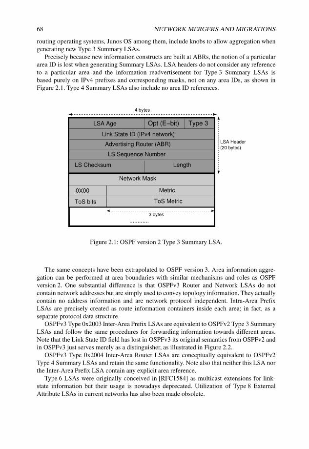
68 NETWORK MERGERS AND MIGRATIONS
routing operating systems, Junos OS among them, include knobs to allow aggregation whengenerating new Type 3 Summary LSAs.
Precisely because new information constructs are built at ABRs, the notion of a particulararea ID is lost when generating Summary LSAs. LSA headers do not consider any referenceto a particular area and the information readvertisement for Type 3 Summary LSAs isbased purely on IPv4 prefixes and corresponding masks, not on any area IDs, as shown inFigure 2.1. Type 4 Summary LSAs also include no area ID references.
4 bytes
LSA Header
(20 bytes)
LSA Age Opt (E−bit) Type 3
LS Checksum Length
Link State ID (IPv4 network)
Advertising Router (ABR)
LS Sequence Number
............
Network Mask
ToS MetricToS bits
3 bytes
0X00Metric
Figure 2.1: OSPF version 2 Type 3 Summary LSA.
The same concepts have been extrapolated to OSPF version 3. Area information aggre-gation can be performed at area boundaries with similar mechanisms and roles as OSPFversion 2. One substantial difference is that OSPFv3 Router and Network LSAs do notcontain network addresses but are simply used to convey topology information. They actuallycontain no address information and are network protocol independent. Intra-Area PrefixLSAs are precisely created as route information containers inside each area; in fact, as aseparate protocol data structure.
OSPFv3 Type 0x2003 Inter-Area Prefix LSAs are equivalent to OSPFv2 Type 3 SummaryLSAs and follow the same procedures for forwarding information towards different areas.Note that the Link State ID field has lost in OSPFv3 its original semantics from OSPFv2 andin OSPFv3 just serves merely as a distinguisher, as illustrated in Figure 2.2.
OSPFv3 Type 0x2004 Inter-Area Router LSAs are conceptually equivalent to OSPFv2Type 4 Summary LSAs and retain the same functionality. Note also that neither this LSA northe Inter-Area Prefix LSA contain any explicit area reference.
Type 6 LSAs were originally conceived in [RFC1584] as multicast extensions for link-state information but their usage is nowadays deprecated. Utilization of Type 8 ExternalAttribute LSAs in current networks has also been made obsolete.
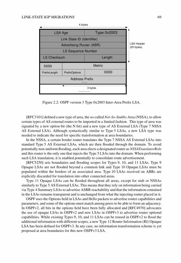
LINK-STATE IGP MIGRATIONS 69
LSA Age Type 0x2003
Link State ID (Identifier)
Advertising Router (ABR)
LS Sequence Number
LS Checksum Length
0X00Metric
Address Prefix
PrefixLength
............
4 bytes
3 bytes
LSA Header
(20 bytes)
PrefixOptions0X00
......
Figure 2.2: OSPF version 3 Type 0x2003 Inter-Area Prefix LSA.
[RFC3101] defined a new type of area, the so-called Not-So-Stubby Area (NSSA), to allowcertain types of AS external routes to be imported in a limited fashion. This type of area wassignaled by a new option bit (the N bit) and a new type of AS External LSA (Type 7 NSSAAS External LSA). Although syntactically similar to Type 5 LSAs, a new LSA type wasneeded to indicate the need for specific transformation at area boundaries.
In the NSSA, a certain border router translates the Type 7 NSSA AS External LSAs intostandard Type 5 AS External LSAs, which are then flooded through the domain. To avoidpotentially non-uniform flooding, each area elects a designated router as NSSATranslatorRoleand this router is the only one that injects the Type 5 LSAs into the domain. When performingsuch LSA translation, it is enabled potentially to consolidate route advertisement.
[RFC5250] sets boundaries and flooding scopes for Types 9, 10, and 11 LSAs. Type 9Opaque LSAs are not flooded beyond a common link and Type 10 Opaque LSAs must bepopulated within the borders of an associated area. Type 10 LSAs received on ABRs areexplicitly discarded for translation into other connected areas.
Type 11 Opaque LSAs can be flooded throughout all areas, except for stub or NSSAssimilarly to Type 5 AS External LSAs. This means that they rely on information being carriedvia Type 4 Summary LSAs to advertise ASBR reachability and that the information containedin the LSAs remains transparent and is unchanged from what the injecting router placed in it.
OSPF uses the Options field in LSAs and Hello packets to advertise router capabilities andparameters, and some of the options must match among peers to be able to form an adjacency.In OSPFv2, all bits in the options field have been fully allocated and [RFC4970] advocatesthe use of opaque LSAs in OSPFv2 and new LSAs in OSPFv3 to advertise router optionalcapabilities. While existing Types 9, 10, and 11 LSAs can be reused in OSPFv2 to flood theadditional information with different scopes, a new Type 12 Router Information (RI) OpaqueLSA has been defined for OSPFv3. In any case, no information transformation scheme is yetproposed at area boundaries for this new OSPFv3 LSA.

70 NETWORK MERGERS AND MIGRATIONS
Table 2.2 summarizes the OSPF transformation rules at area boundaries.
Table 2.2 Analysis of LSA transformation at area boundaries
LSA Type at originating Area Transformed LSA Type at external Area
Type 1 v2 Router Summarized in Type 3 LSA
Type 0x2001 v3 Router Summarized in Type 0x2003 LSA
Type 2 v2 Network Summarized in Type 3 LSA
Type 0x2002 v3 Network Summarized in Type 0x2003 LSA
Type 3 v2 Summary Not applicable
Type 0x2003 v3 Inter-Area Prefix Not applicable
Type 4 v2 Summary Not applicable
Type 0x2004 v3 Inter-Area Router Not applicable
Type 5 v2 AS External Flooded without manipulation, Type 4LSA for advertising router
Type 0x4005 v3 AS External Flooded without manipulation, Type0x2004 LSA for advertising router
Type 6 v2 Multicast Extensions Not applicable
Type 0x2006 v3 Multicast Extensions Deprecated
Type 7 v2 NSSA AS External Translated to Type 5 LSA, unconditionallyor by NSSATranslatorRole
Type 0x2007 v3 NSSA AS External Translated to Type 0x4005 LSA,unconditionally or byNSSATranslatorRole
Type 8 v2 External Attributes Not applicable
Type 0x0008 v3 Link Not applicable
Type 9 v2 Opaque Link-local scope, not applicable
Type 0x2009 v3 Intra-Area Prefix Summarized in Type 0x2003 LSA
Type 10 v2 Opaque Area scope, not applicable
Type 11 v2 Opaque Domain scope, not flooded to stub orNSSAs
Type 12 v3 Router Information Opaque Varying scope, no transformation
Hierarchy identification in IS–IS networks: IS–IS has a completely different approachto area correspondence and boundaries when compared to OSPF.
The first fundamental divergence is the placement of area boundaries. In OSPF, thedemarcation line crosses the router, in the sense that a logical interface can belong only toone area (with the known exception of multi-area adjacencies) and the router in this case acts

LINK-STATE IGP MIGRATIONS 71
as ABR with interfaces inside each area. In IS–IS, the Intermediate System is fully insideone (or more than one) area. A router can set up more than one adjacency over the same link,either a Level 1 or a Level 2 adjacency, or an adjacency in both levels.
The IS–IS area identifier is not a compulsorily matching parameter for neighbor relation-ships as it is in OSPF. Only Level 1 adjacencies need to be circumvented inside a commonarea, because there is no such concept of a Level 2 area. An IS–IS Level 2 is nothing morethan a contiguous collection of backbone routers that do not necessarily belong to a particulararea. This fact notably relaxes connectivity requirements in the backbone when consideringa hierarchical alignment, because Level 2 adjacencies do not impose matching areas onparticipating routers.
Level 1 routers do not actually know the identity of routers or destinations outsideof their area per original concept. They install a default route pointing to L1L2 routersthat set the ATTached bit in their Level 1 LSPs but ignore possible area duplicationsoutside their island. Level 2 routers also ignore the particular Level 1 area topology androuting information, except for the directly attached Level 1 areas when acting as L1L2routers.
[RFC1195] already opens the door for the possibility of an area having multiple addresses,something wholly inconceivable in OSPF. The reasoning behind this scheme is to enablegraceful transitions for migrating, merging, or partitioning areas. Areas are configured oneach intermediate system and in the case of multiple configured areas, the same criteria applyfor Level 1 adjacencies to be established: an intermediate system will refuse to become aneighbor with a node if none of its area addresses overlaps its own configured areas. Thatis to say, a minimum of a single matching area identifier is enough for a unique Level 1adjacency to be set up. From that perspective, IS–IS areas are another Level 1 adjacencysetup control mechanism.
In this situation, a single system that maintains more than one IS–IS Level 1 adjacencyin different areas in effect performs area merging. Flooding scopes from diverse areas arestitched together at the point where the router contains at least one IS–IS Level 1 adjacencyin each of them. Because route information is transparently flooded over these interconnectpoints, such bypasses also remain eligible for path computation.
Area recognition is first performed when inspecting the initial data available with eachIS–IS PDU. This information is first referred in the Maximum Area Addresses field, which isincluded in the IS–IS header of all PDUs, as displayed in Figure 2.3. This provides an initialreference for the maximum number of areas.
The definitive information pointer regarding the IS–IS areas configured in a system is theso-called TLV 1 Area, shown in Figure 2.4. It consists of a sequence of area IDs and theirlengths coded in a TLV. As per OSI addressing, an IS–IS area identifier can be 13 bytes longat most, and the theoretical constraint for the number of areas is imposed by a maximum of255 bytes of TLV data, although routing operating systems tend to impose a lower boundarythan this.
Such TLVs are mandatory to appear in all types of IS–IS Hello PDU and LSP (bothfor Level 1 and Level 2) because they contain substantial information used for establishingadjacencies and performing the SPF computation.
The original TLVs advocated for IPv4 information, defined in [RFC1195], were TLV 128Internal IP Reachability and TLV 130 External IP Reachability to include internal (local anddirect) and external (redistributed) routing information advertised by an intermediate system,

72 NETWORK MERGERS AND MIGRATIONS
IntraDomain Routing Protocol Discriminator (0x83)
Header Length Indicator
Version/Protocol ID Extension (1)
ID Length (0)
R(0) PDU Type
PDU specific fields
1 byte
R(0) R(0)
Version (0)
Reserved (0)
Maximum Area Addresses
TLVs
IS−IS Header
(8 bytes)
17−33 bytes
0−1467 bytes
Figure 2.3: Common IS–IS header including Maximum Area Addresses field.
respectively. Figures 2.5 and 2.6 both depict IPv4-related TLVs. The intent is for L1L2routers to extract and insert IPv4 routes in the corresponding LSPs at area boundariesaccording to the default protocol behavior, so there is no one-to-one correspondence amongTLVs across levels, but these data structures are regenerated following policies and rules ateach router.
Actually, by default, route population across IS–IS levels is constrained. IS–IS L1L2routers do not propagate any routing information from Level 2 to Level 1 areas by default.It is expected that L1 systems will install a default route based on ATTached bit detectionand L1L2 routers set it based on their backbone connectivity (meaning in the case of JunosOS reachability of external areas through the backbone) and active IS–IS adjacencies. Thismechanism is somewhat equivalent to a Totally Stubby Area in OSPF because in both, theonly available external data is a default route pointing to the core exit points.
A further default restriction in the original IS–IS prohibited utilization of TLV 130External IP Reachability in Level 1 areas. As a result, no external L2 routes could be leakedto Level 1 systems. This opacity between layers was considered a safeguard mechanismwhen the original IS–IS specification was written, but soon became unpractical in the IPenvironment.
[RFC2966] relaxed this original constraint by allowing backbone routes to be leaked toL1 areas, reusing the high-order bit in the default metric field in TLVs 128 and 130 to be theso-called Up/Down bit. Routers at level boundaries must set this bit for those TLVs injectedin Level 1 areas containing information propagated from the core. In this way, L1L2 routerscan determine which route information has been passed to an L1 area and can avoid creatinga routing loop by re-injecting it in the backbone.

LINK-STATE IGP MIGRATIONS 73
TLV Type (0x01)
TLV Length (1−255)
Area Length
1 byte
Area ID
1 byte
1−13 bytes
1 byte
1 byte
1 byte
1−13 bytes
Area Length
Area ID
Figure 2.4: IS–IS TLV 1 Area.
This RFC also loosened the initial restriction on using the TLV 130 External IPReachability in Level 1 areas so that a simple L1 router could now inject route informationexternal into the domain, as opposed into a purely Totally Stubby Area in OSPF.
Both these changes considerably influenced IS–IS route population mechanisms and stan-dardized domain-wide prefix distribution with different preferences and redistribution rules.
Nevertheless, there were still two other major restrictions with both TLVs 128 and 130:their definition restricted the metric value to a maximum length of 6 bits and they didnot allow further expansibility to attach additional information to each route. These samerestrictions applied to TLV 2 IS Reachability which defined intermediate system connectivity,the foundations for the SPF calculation.
[RFC3784] further leveraged both restrictions by means of the definition of additionalTLVs, namely TLV 22 Extended IS Reachability and TLV 135 Extended IP Reachability.These new expanded TLVs granted additional metric space, with values up to 24-bit wideand added TE Sub-TLVs. However, they did not consider any internal or external prefixdistinction. The leaking concept based on setting an Up/Down bit is still valid and mandatorythough, in order to avoid potential loops (especially when removing the protocol preferencedistinction between external and internal prefixes).
In the previous and current implementations of IS–IS, L1L2 routers no longer inject area-specific information from one level into another. The Maximum Area Addresses field in theIS–IS header is set for supportability purposes and although TLV 1 Area is included in LSPsand all Hello PDUs, it is mostly used only for adjacency establishment and ATTached bitsetting purposes, not for SPF calculations.

74 NETWORK MERGERS AND MIGRATIONS
TLV Type (128)
TLV Length (Number of prefixes x 12)
1 byte
1 byte
1 byte
1 byte
4 bytes
Default Metric
Subnet mask
R I/E
1 byteDelay MetricS I/E
1 byteExpense MetricS I/E
1 byteError MetricS I/E
IP prefix
4 bytes
Repeated
for each
prefix
Figure 2.5: IS–IS TLV 128 Internal IP Reachability.
TLV Type (130)
TLV Length (Number of prefixes x 12)
1 byte
1 byte
1 byte
1 byte
4 bytes
Default Metric
Subnet mask
R I/E
1 byteDelay MetricS I/E
1 byteExpense MetricS I/E
1 byteError MetricS I/E
IP prefix
4 bytes
Repeated
for each
prefix
Figure 2.6: IS–IS TLV 130 External IP Reachability.

LINK-STATE IGP MIGRATIONS 75
When manipulating topology information at L1L2 routers, neither the old-style nor new-style IPv4 reachability TLVs contain any area ID reference. It is the responsibility of theL1L2 router to propagate route information between TLVs in different LSPs in both levels.
When evaluating route-leaking across levels, a noticeable exception to routing informationpopulation is area merging that occurs by stitching together different IS–IS Level 1 adjacen-cies in diverse areas. In this case, a formal combination of interconnected areas occurs, as ifit were a single area in terms of flooding and route computation.
Because area identification remains relevant for local adjacency establishment andATTached bit setting, and because Junos OS does not implement the partition repair function,duplication or coincidence in area codes in different parts of the backbone is irrelevant toensuring end-to-end connectivity.
Adjacency transition
Because both OSPF and IS–IS prefer intra-area paths to inter-area paths, a smooth adjacencymigration is vital to the success of any effort to merge, segregate, or renumber a particulararea.
Adjacency transition in OSPF: The traditional interface-area association advocated inOSPF poses a problem when extending or shrinking areas in an OSPF backbone, sincemoving an interface from one area to another (in all media types) becomes an intrusiveoperation.
[RFC5185] introduces the concept of multi-area adjacencies with ABRs being able toestablish multiple point-to-point adjacencies belonging to different areas. Each point-to-pointlink provides a topological connection eligible for flooding and path computation within aparticular area. A new Router LSA for each secondary area is created once the secondaryadjacencies are established, and it contains only point-to-point network information forthat area to represent the link to another router. However, the Router LSA contains noextra stub link information for the common network; nor does it contain any extra Type 3LSA generation for the associated subnet in order to avoid address overlapping with theinformation present in the primary area.
Because of the nature of this behavior, these multi-area adjacencies are implicitly point-to-point relationships, so broadcast and NBMA OSPF link types cannot join them. Onlypoint-to-point links and LAN media operating in a point-to-point fashion allow multi-areaneighbor relationships.
Application Note: OSPF area migrations through secondaryadjacencies
Figure 2.7 presents a subset of our well-known topology with the same OSPF areaconfigured in different parts of the network.
In OSPF, duplicate non-backbone areas can coexist in a common backbone with end-to-end connectivity. Listing 2.1 shows the output of the OSPF database from router Male’spoint of view and Listing 2.2 from router Barcelona. Note that although they are internalrouters inside an area with the same identifier, their corresponding OSPF databases arecompletely different.

76 NETWORK MERGERS AND MIGRATIONS
Area 0.0.0.3
Area 0.0.0.0
Area 0.0.0.3
Male
Bilbao
Havana
Nantes
Skopie
Livorno Barcelona
Honolulu
192.168.1.4
192.168.1.20
192.168.1.8
192.168.1.1
192.168.1.2
192.168.1.6 192.168.1.7
192.168.1.21
Maximum link metric
Figure 2.7: Network topology with duplicated Area 0.0.0.3.
Listing 2.1: OSPF database at Male
1 user@male-re0> show ospf database | no-more2
3 OSPF database, Area 0.0.0.34 Type ID Adv Rtr Seq Age Opt Cksum Len5 Router 192.168.1.4 192.168.1.4 0x8000000c 428 0x22 0x52d0 366 Router 192.168.1.8 192.168.1.8 0x8000000b 364 0x22 0x4e53 487 Router *192.168.1.20 192.168.1.20 0x8000000f 102 0x22 0x7c52 728 Network *172.16.1.85 192.168.1.20 0x80000005 1378 0x22 0xe5d4 329 Summary 172.16.1.4 192.168.1.4 0x8000000d 428 0x22 0x8f72 28
10 Summary 172.16.1.4 192.168.1.8 0x8000000b 364 0x22 0x718f 2811 <...>12 Summary 172.16.1.52 192.168.1.4 0x80000006 428 0x22 0xbb1d 2813 Summary 172.16.1.52 192.168.1.8 0x80000005 364 0x22 0xb91a 2814 <...> # Summary LSAs for loopbacks beyond local Area15 Summary 192.168.1.1 192.168.1.4 0x80000009 428 0x22 0x91c8 2816 Summary 192.168.1.1 192.168.1.8 0x80000008 364 0x22 0x7bdb 2817 Summary 192.168.1.2 192.168.1.4 0x80000009 428 0x22 0x87d1 2818 Summary 192.168.1.2 192.168.1.8 0x80000008 364 0x22 0x7bd9 2819 Summary 192.168.1.3 192.168.1.4 0x80000009 428 0x22 0x7dda 2820 Summary 192.168.1.3 192.168.1.8 0x80000008 364 0x22 0x71e2 2821 <...>22 Summary 192.168.1.21 192.168.1.4 0x80000005 428 0x22 0xda6e 2823 Summary 192.168.1.21 192.168.1.8 0x80000004 364 0x22 0xd86b 2824 <...>25 OpaqArea 1.0.0.1 192.168.1.4 0x80000001 428 0x22 0xbc95 2826 OpaqArea 1.0.0.1 192.168.1.8 0x80000001 364 0x22 0xcc7d 2827 OpaqArea*1.0.0.1 192.168.1.20 0x80000001 102 0x22 0xfc35 2828 OpaqArea 1.0.0.3 192.168.1.4 0x80000002 293 0x22 0x1a39 12429 OpaqArea 1.0.0.3 192.168.1.8 0x80000002 41 0x22 0x9dee 12430 OpaqArea*1.0.0.3 192.168.1.20 0x80000001 102 0x22 0x9da7 12431 OpaqArea*1.0.0.4 192.168.1.20 0x80000001 102 0x22 0x25f2 136
Listing 2.2: OSPF database at Barcelona
1 user@Barcelona-re0> show ospf database | no-more2
3 OSPF link state database, Area 0.0.0.3

LINK-STATE IGP MIGRATIONS 77
4 Type ID Adv Rtr Seq Age Opt Cksum Len5 Router 192.168.1.6 192.168.1.6 0x8000000b 527 0x22 0xa978 486 Router *192.168.1.7 192.168.1.7 0x80000008 139 0x22 0x6335 1207 Router 192.168.1.21 192.168.1.21 0x80000006 227 0x22 0x7af5 488 Network *172.16.1.53 192.168.1.7 0x80000003 1728 0x22 0x13e1 329 Network 172.16.1.89 192.168.1.6 0x80000005 314 0x22 0x744d 32
10 Summary 172.16.1.4 192.168.1.6 0x80000008 526 0x22 0x976c 2811 <...>12 Summary 172.16.1.84 192.168.1.6 0x80000006 526 0x22 0x6e48 2813 <...> # Summary LSAs for loopbacks beyond local Area14 Summary 192.168.1.1 192.168.1.6 0x80000006 526 0x22 0x95c4 2815 Summary 192.168.1.2 192.168.1.6 0x80000006 526 0x22 0x81d8 2816 Summary 192.168.1.3 192.168.1.6 0x80000006 526 0x22 0x81d6 2817 <...>18 Summary 192.168.1.20 192.168.1.6 0x80000006 526 0x22 0xd670 2819 <...>20 OpaqArea 1.0.0.1 192.168.1.6 0x80000001 527 0x22 0xc489 2821 OpaqArea*1.0.0.1 192.168.1.7 0x80000001 139 0x22 0xc883 2822 OpaqArea 1.0.0.1 192.168.1.21 0x80000001 227 0x22 0x12f 2823 OpaqArea 1.0.0.3 192.168.1.6 0x80000002 258 0x22 0x870a 12424 OpaqArea*1.0.0.3 192.168.1.7 0x80000001 139 0x22 0x652d 12425 OpaqArea 1.0.0.3 192.168.1.21 0x80000001 227 0x22 0x86b4 12426 OpaqArea 1.0.0.4 192.168.1.6 0x80000002 203 0x22 0xb692 124
It is interesting to note that both routers see each other via Type 3 Summary LSAsinjected by the corresponding ABRs as per Listings 2.3 and 2.4, similar to what would alsobe expected with different area identifiers.
Listing 2.3: Barcelona loopback address topological information at Male
1 user@male-re0> show ospf database extensive lsa-id 192.168.1.72
3 OSPF database, Area 0.0.0.34 Type ID Adv Rtr Seq Age Opt Cksum Len5 Summary 192.168.1.7 192.168.1.4 0x8000000d 168 0x22 0x6dec 28 # Injected by Havana6 mask 255.255.255.2557 Topology default (ID 0) -> Metric: 16468 Aging timer 00:58:499 Installed 00:01:10 ago, expires in 00:58:49, sent 00:01:10 ago
10 Last changed 00:01:10 ago, Change count: 711 Summary 192.168.1.7 192.168.1.8 0x8000000c 495 0x22 0x5ff5 28 # Injected by Bilbao12 mask 255.255.255.25513 Topology default (ID 0) -> Metric: 100314 Aging timer 00:58:4915 Installed 00:01:10 ago, expires in 00:58:49, sent 00:01:10 ago16 Last changed 00:01:10 ago, Change count: 6
Listing 2.4: Male loopback address topological information at Barcelona
1 user@Barcelona-re0> show ospf database extensive lsa-id 192.168.1.202
3 OSPF link state database, Area 0.0.0.34 Type ID Adv Rtr Seq Age Opt Cksum Len5 Summary 192.168.1.20 192.168.1.6 0x8000000d 611 0x22 0xd670 28 # Injected by Livorno6 mask 255.255.255.2557 Topology default (ID 0) -> Metric:15468 Aging timer 00:57:179 Installed 00:02:41 ago, expires in 00:57:18, sent 00:02:41 ago
10 Last changed 00:02:41 ago, Change count: 6
These standard translation mechanisms at area boundaries ensure end-to-endconnectivity, independently of the area identifier. Assume in this case that the link between

78 NETWORK MERGERS AND MIGRATIONS
router Havana and router Livorno has a maximum metric, much higher than the path overrouter Nantes and router Skopie, so the traffic between both ends will take this alternatepath in the backbone, as per Listing 2.5.
Listing 2.5: Traceroute from Male to Barcelona
1 user@male-re0> traceroute 192.168.1.7 source 192.168.1.202 traceroute to 192.168.1.7 (192.168.1.7) from 192.168.1.20, 30 hops max, 40 byte packets3 1 bilbao-so1310 (172.16.1.78) 0.503 ms 0.424 ms 0.433 ms4 2 nantes-ge1300 (172.16.1.6) 0.518 ms 0.441 ms 0.433 ms5 3 skopie-so0100 (172.16.1.2) 0.540 ms 0.443 ms 0.464 ms6 4 livorno-so0000 (172.16.1.34) 0.490 ms 0.492 ms 0.457 ms7 5 barcelona (192.168.1.7) 0.726 ms 0.618 ms 0.617 ms
The intention of the migration in this case is to merge both non-backbone areas with thehelp of an OSPF multi-area adjacency (both in Areas 0.0.0.0 and 0.0.0.3) between routerHavana and router Livorno as in Figure 2.8. In this way, standard routing policies fromOSPF, where intra-area paths are preferred against inter-area paths, are enforced to takethat particular link despite its maximum metric, preferring that path to the lower cost viarouter Skopie and router Nantes.
Area 0.0.0.0
Male
Bilbao
Havana
Nantes
Skopie
Livorno Barcelona
Honolulu
192.168.1.4
192.168.1.20
192.168.1.8
192.168.1.1
192.168.1.2
192.168.1.6 192.168.1.7
192.168.1.21
Merged Area 0.0.0.3
Maximum link metric
Figure 2.8: Network topology merging Area 0.0.0.3 with multi-area adjacency betweenHavana and Livorno.
Multi-area adjacencies are configured in Junos OS by adding the secondarystatement to the link in the desired OSPF area. With this tag, the router attempts to establisha parallel OSPF adjacency over the same point-to-point link with a different area ID.However, other link parameters and attributes, such as timers and authentication, can beconfigured differently. Listing 2.6 shows the configuration stanzas on router Havana androuter Livorno for this purpose, with the activation knobs on Lines 19 and 41.
Listing 2.6: OSPF multi-area configuration for link between Havana and Livorno
1 user@Livorno> show configuration protocols ospf2 traffic-engineering;

LINK-STATE IGP MIGRATIONS 79
3 area 0.0.0.0 {4 interface so-0/0/1.0 {5 metric 65535;6 }7 interface so-0/0/2.0;8 interface fe-0/3/0.0;9 interface lo0.0 {
10 passive;11 }12 interface so-0/0/0.0;13 }14 area 0.0.0.3 {15 interface ge-0/2/0.0;16 interface ge-1/3/0.0;17 interface so-0/0/1.0 {18 metric 65535;19 secondary; # Knob for multi-area adjacency20 }21 }22 user@Havana> show configuration protocols ospf23 traffic-engineering;24 area 0.0.0.0 {25 interface so-0/1/0.0;26 interface at-0/2/0.1001;27 interface so-1/0/0.0 {28 metric 65535;29 }30 interface so-1/0/1.0;31 interface so-1/0/2.0;32 interface so-1/0/3.0;33 interface lo0.0 {34 passive;35 }36 }37 area 0.0.0.3 {38 interface ge-1/1/0.0;39 interface so-1/0/0.0 {40 metric 65535;41 secondary; # Knob for multi-area adjacency42 }43 }
Once this new adjacency is transparently established (the remaining one in Area 0.0.0.0is not affected), both router Male and router Barcelona share the same OSPF database, asdisplayed in Listing 2.7. It is worth mentioning that three ABRs between Area 0.0.0.0 andArea 0.0.0.3 exist at this point and therefore Type 3 Summary LSAs are injected to Area0.0.0.3 at three different points. For instance, Lines 18, 19, and 20, respectively, show howrouter Nantes is visible via Type 3 Summary LSAs injected at these three ABRs: routerHavana, router Livorno, and router Bilbao.
Listing 2.7: OSPF databases in Male and Barcelona after secondary link activation
1 user@male-re0> show ospf database | no-more2
3 OSPF database, Area 0.0.0.34 Type ID Adv Rtr Seq Age Opt Cksum Len5 Router 192.168.1.4 192.168.1.4 0x80000014 73 0x22 0xbf9a 486 Router 192.168.1.6 192.168.1.6 0x80000012 70 0x22 0x4913 607 Router 192.168.1.7 192.168.1.7 0x8000000e 879 0x22 0x6335 1208 Router 192.168.1.8 192.168.1.8 0x8000000f 681 0x22 0x4c54 489 Router *192.168.1.20 192.168.1.20 0x80000017 917 0x22 0x7c52 72
10 Router 192.168.1.21 192.168.1.21 0x8000000e 964 0x22 0x7af5 4811 Network 172.16.1.53 192.168.1.7 0x80000009 492 0x22 0x11e2 3212 Network *172.16.1.85 192.168.1.20 0x80000002 106 0x22 0xe3d5 32

80 NETWORK MERGERS AND MIGRATIONS
13 Network 172.16.1.89 192.168.1.6 0x80000009 148 0x22 0x724e 3214 Summary 172.16.1.4 192.168.1.4 0x8000000f 76 0x22 0x8975 28 # Havana ABR15 Summary 172.16.1.4 192.168.1.6 0x80000013 74 0x22 0x916f 28 # Livorno ABR16 Summary 172.16.1.4 192.168.1.8 0x8000000e 311 0x22 0x6f90 28 # Bilbao ABR17 <...>18 Summary 192.168.1.1 192.168.1.4 0x8000000d 76 0x22 0x8dca 28 # Havana ABR19 Summary 192.168.1.1 192.168.1.6 0x8000000a 74 0x22 0x91c6 28 # Livorno ABR20 Summary 192.168.1.1 192.168.1.8 0x80000001 1179 0x22 0x7bdb 28 # Bilbao ABR21 Summary 192.168.1.2 192.168.1.4 0x8000000d 76 0x22 0x83d3 2822 Summary 192.168.1.2 192.168.1.6 0x80000009 74 0x22 0x7dda 2823 Summary 192.168.1.2 192.168.1.8 0x80000001 1179 0x22 0x7bd9 2824 <...>25 OpaqArea 1.0.0.1 192.168.1.4 0x800000010 77 0x22 0xb698 2826 OpaqArea 1.0.0.1 192.168.1.6 0x8000000d 74 0x22 0xbe8c 2827 OpaqArea 1.0.0.1 192.168.1.7 0x8000000a 879 0x22 0xc883 2828 OpaqArea 1.0.0.1 192.168.1.8 0x8000000b 672 0x22 0xca7e 2829 OpaqArea*1.0.0.1 192.168.1.20 0x8000000b 917 0x22 0xfc35 2830 OpaqArea 1.0.0.1 192.168.1.21 0x8000000a 964 0x22 0x12f 2831 <...>
At this time, both routers see their respective loopback addresses via Router LSAs asthey are now part of the same merged area, as shown in Listing 2.8.
Listing 2.8: Barcelona loopback address present at Male via Router LSA
1 user@male-re0> show ospf database extensive lsa-id 192.168.1.72
3 OSPF database, Area 0.0.0.34 Type ID Adv Rtr Seq Age Opt Cksum Len5 Router 192.168.1.7 192.168.1.7 0x8000000e 362 0x22 0xae56 726 bits 0x2, link count 47 id 172.16.1.105, data 172.16.1.106, Type Transit (2)8 Topology count: 0, Default metric: 1009 id 172.16.1.54, data 172.16.1.53, Type Transit (2)
10 Topology count: 0, Default metric: 10011 id 192.168.1.7, data 255.255.255.255, Type Stub (3) # Barcelona’s loopback12 Topology count: 0, Default metric: 013 Aging timer 00:53:5714 Installed 00:05:55 ago, expires in 00:53:58, sent 00:05:53 ago15 Last changed 00:09:33 ago, Change count: 1
For end-to-end connectivity, this intra-area path is selected, independent of any metricvalues of alternate paths in the backbone, as shown in Listing 2.9.
Listing 2.9: Traceroute from Male to Barcelona with merged Area
1 user@male-re0> traceroute 192.168.1.7 source 192.168.1.202 traceroute to 192.168.1.7 (192.168.1.7) from 192.168.1.20, 30 hops max, 40 byte packets3 1 havana-ge1100 (172.16.1.86) 0.540 ms 0.422 ms 0.432 ms4 2 livorno-so0010 (172.16.1.38) 0.475 ms 0.440 ms 0.427 ms5 3 barcelona (192.168.1.7) 0.708 ms 0.597 ms 0.595 ms
Once a secondary adjacency is established, the Router LSA for the particular areadoes not include any stub network information to represent the link addressing, so as toavoid possible overlaps. That Router LSA in the new area includes only a point-to-pointnetwork type referring to the ifIndex (as if it were an unnumbered link) to represent thisadditional binding inside the network.
Junos OS enforces the requirement that, at most, only one link definition is defined asthe primary (there could be no primaries at all), but the configuration can have as manysecondary adjacencies as desired.

LINK-STATE IGP MIGRATIONS 81
Adding a secondary adjacency in Junos OS has no direct impact or side effects on theexisting primary relationship. The primary adjacency remains in FULL state while buildingup new secondary adjacencies.
Junos Tip: Unnumbered point-to-point interfaces in OSPFv2
Unnumbered point-to-point interfaces appear in each Type 1 Router LSA with itscorresponding point-to-point network type for established adjacencies and in the caseof Junos OS, referring to ifIndex for the respective interface. Link addressing is actuallysignified by stub network types in Router LSAs.
This behavior has been extended to different LSA types in OSPFv3, where link-addressing information is kept in different data structures from system reachability,similar to IS–IS.
Network engineers tend to define addresses on backbone point-to-point interfaces forvarious reasons, including the following:
• operational purposes, such as an easy link identification in a traceroute or ping;
• TE purposes with RSVP-TE, such as explicit link addition as part of an RSVP;
• management purposes, such as restricting connections from an address range.
Notice that protocol extensions to traceroute and RSVP are being discussed tofacilitate deployment of unnumbered links in the network.
Apart from these applications, a point-to-point-based network could run perfectly onunnumbered interfaces with unique references in each point-to-point network type entryin Type 1 Router LSAs.
When transitioning from primary to secondary or vice versa, OSPF neighbors needto be fully renegotiated and adjacencies need to be established. Listings 2.10 and 2.11show the Router LSAs from router Livorno in each area before the primary adjacency ismoved from Area 0.0.0.0 to Area 0.0.0.3 (achieved with a single commit and simultaneousOSPF adjacency formation with new data). Note the specific reference to the point-to-pointnetwork as either the ifIndex or stub data in Lines 14 and 36, and the injection of the linkaddressing via stub network in Line 16 in Listing 2.10 before the migration, and how thisis represented on Lines 14, 34, and 36 at Listing 2.11 after the migration.
Listing 2.10: Router LSAs from Livorno with primary adjacency in Area 0.0.0.0
1 user@Livorno> show ospf database router lsa-id 192.168.1.6 extensive2
3 OSPF database, Area 0.0.0.04 Type ID Adv Rtr Seq Age Opt Cksum Len5 Router *192.168.1.6 192.168.1.6 0x800006a9 512 0x22 0x7fe9 1086 bits 0x1, link count 77 <...>8 id 192.168.1.6, data 255.255.255.255, Type Stub (3)9 Topology count: 0, Default metric: 0
10 id 192.168.1.2, data 172.16.1.34, Type PointToPoint (1)11 Topology count: 0, Default metric: 64312 id 172.16.1.32, data 255.255.255.252, Type Stub (3)

82 NETWORK MERGERS AND MIGRATIONS
13 Topology count: 0, Default metric: 64314 id 192.168.1.4, data 172.16.1.38, Type PointToPoint (1) # P2P to Havana15 Topology count: 0, Default metric: 65535 # Maximum metric16 id 172.16.1.36, data 255.255.255.252, Type Stub (3) # Link addresses to Havana17 Topology count: 0, Default metric: 65535 # Maximum metric18 Topology default (ID 0)19 Type: PointToPoint, Node ID: 192.168.1.420 Metric: 65535, Bidirectional # Maximum metric21 Type: PointToPoint, Node ID: 192.168.1.222 Metric: 643, Bidirectional23 Gen timer 00:40:1424 Aging timer 00:51:2825 Installed 00:08:32 ago, expires in 00:51:28, sent 00:08:30 ago26 Last changed 00:08:37 ago, Change count: 31, Ours27
28 OSPF database, Area 0.0.0.329 Type ID Adv Rtr Seq Age Opt Cksum Len30 Router *192.168.1.6 192.168.1.6 0x80000014 518 0x22 0xe80 6031 bits 0x1, link count 332 id 172.16.1.54, data 172.16.1.54, Type Transit (2)33 Topology count: 0, Default metric: 10034 id 172.16.1.89, data 172.16.1.89, Type Transit (2)35 Topology count: 0, Default metric: 10036 id 192.168.1.4, data 0.0.0.70, Type PointToPoint (1) # P2P to Havana37 Topology count: 0, Default metric: 65535 # Maximum metric38 Topology default (ID 0)39 Type: PointToPoint, Node ID: 192.168.1.440 Metric: 65535, Bidirectional # Maximum metric41 Type: Transit, Node ID: 172.16.1.8942 Metric: 100, Bidirectional43 Type: Transit, Node ID: 172.16.1.5444 Metric: 100, Bidirectional45 Gen timer 00:32:3046 Aging timer 00:51:2247 Installed 00:08:38 ago, expires in 00:51:22, sent 00:08:36 ago48 Last changed 00:26:17 ago, Change count: 5, Ours
Listing 2.11: Router LSAs from Livorno with primary adjacency in Area 0.0.0.3
1 user@Livorno> show ospf database router lsa-id 192.168.1.6 extensive2
3 OSPF database, Area 0.0.0.04 Type ID Adv Rtr Seq Age Opt Cksum Len5 Router *192.168.1.6 192.168.1.6 0x800006ad 18 0x22 0xba37 966 bits 0x1, link count 67 <...>8 id 192.168.1.6, data 255.255.255.255, Type Stub (3)9 Topology count: 0, Default metric: 0
10 id 192.168.1.2, data 172.16.1.34, Type PointToPoint (1)11 Topology count: 0, Default metric: 64312 id 172.16.1.32, data 255.255.255.252, Type Stub (3)13 Topology count: 0, Default metric: 64314 id 192.168.1.4, data 0.0.0.70, Type PointToPoint (1) # P2P to Havana15 Topology count: 0, Default metric: 65535 # Maximum metric16 Topology default (ID 0)17 Type: PointToPoint, Node ID: 192.168.1.418 Metric: 65535, Bidirectional # Maximum metric19 Type: PointToPoint, Node ID: 192.168.1.220 Metric: 643, Bidirectional21 Gen timer 00:43:2822 Aging timer 00:59:4123 Installed 00:00:18 ago, expires in 00:59:42, sent 00:00:18 ago24 Last changed 00:00:18 ago, Change count: 35, Ours25
26 OSPF database, Area 0.0.0.327 Type ID Adv Rtr Seq Age Opt Cksum Len28 Router *192.168.1.6 192.168.1.6 0x80000018 18 0x22 0xd429 72

LINK-STATE IGP MIGRATIONS 83
29 bits 0x1, link count 430 id 172.16.1.54, data 172.16.1.54, Type Transit (2)31 Topology count: 0, Default metric: 10032 id 172.16.1.89, data 172.16.1.89, Type Transit (2)33 Topology count: 0, Default metric: 10034 id 192.168.1.4, data 172.16.1.38, Type PointToPoint (1) # P2P to Havana35 Topology count: 0, Default metric: 65535 # Maximum metric36 id 172.16.1.36, data 255.255.255.252, Type Stub (3) # Link addresses to Havana37 Topology count: 0, Default metric: 65535 # Maximum metric38 Topology default (ID 0)39 Type: PointToPoint, Node ID: 192.168.1.440 Metric: 65535, Bidirectional # Maximum metric41 Type: Transit, Node ID: 172.16.1.8942 Metric: 100, Bidirectional43 Type: Transit, Node ID: 172.16.1.5444 Metric: 100, Bidirectional45 Gen timer 00:44:2146 Aging timer 00:59:4147 Installed 00:00:18 ago, expires in 00:59:42, sent 00:00:18 ago48 Last changed 00:00:18 ago, Change count: 9, Ours
Another interesting factor to consider in multi-area adjacencies is that Opaque LSAs aregenerated with the same TE attributes for the binding in all active areas, thus enabling asimilar view of the link in each TE database (TED). Listing 2.12 displays the TE OpaqueLSAs for the link at each area after a multi-area adjacency has been established. Forinstance, the same admin-group is included in them as pointed out in Lines 27 and 61in each area.
Listing 2.12: Opaque LSAs from Livorno for multi-area adjacency link
1 user@Livorno> show ospf database opaque-area area 0.0.0.0 extensive2 advertising-router 192.168.1.6 lsa-id 1.0.0.53
4 OSPF database, Area 0.0.0.05 Type ID Adv Rtr Seq Age Opt Cksum Len6 OpaqArea*1.0.0.5 192.168.1.6 0x80000001 425 0x22 0xe38c 1287 Area-opaque TE LSA8 Link (2), length 104:9 Linktype (1), length 1:
10 111 LinkID (2), length 4:12 192.168.1.413 RemIfAdr (4), length 4:14 172.16.1.3715 TEMetric (5), length 4:16 65535 # Maximum metric17 MaxBW (6), length 4:18 155.52Mbps19 MaxRsvBW (7), length 4:20 155.52Mbps21 UnRsvBW (8), length 32:22 Priority 0, 155.52Mbps23 <...>24 LinkLocalRemoteIdentifier (11), length 8:25 Local 70, Remote 026 Color (9), length 4:27 8 # Admin-group28 Gen timer 00:29:3829 Aging timer 00:52:5430 Installed 00:07:05 ago, expires in 00:52:55, sent 00:07:05 ago31 Last changed 00:07:05 ago, Change count: 1, Ours, TE Link ID: 214748365732
33 user@Livorno> show ospf database opaque-area area 0.0.0.3 extensive34 advertising-router 192.168.1.6 lsa-id 1.0.0.635
36 OSPF database, Area 0.0.0.3

84 NETWORK MERGERS AND MIGRATIONS
37 Type ID Adv Rtr Seq Age Opt Cksum Len38 OpaqArea*1.0.0.6 192.168.1.6 0x80000001 498 0x22 0xa0d3 13639 Area-opaque TE LSA40 Link (2), length 112:41 Linktype (1), length 1:42 143 LinkID (2), length 4:44 192.168.1.445 LocIfAdr (3), length 4:46 172.16.1.3847 RemIfAdr (4), length 4:48 172.16.1.3749 TEMetric (5), length 4:50 65535 # Maximum metric51 MaxBW (6), length 4:52 155.52Mbps53 MaxRsvBW (7), length 4:54 155.52Mbps55 UnRsvBW (8), length 32:56 Priority 0, 155.52Mbps57 <...>58 LinkLocalRemoteIdentifier (11), length 8:59 Local 70, Remote 060 Color (9), length 4:61 8 # Admin-group62 Gen timer 00:29:1863 Aging timer 00:51:4164 Installed 00:08:18 ago, expires in 00:51:42, sent 00:08:18 ago65 Last changed 00:08:18 ago, Change count: 1, Ours, TE Link ID: 2147483657
Despite its fundamental restriction to be applicable only for point-to-point link typesand the implicit adjacency reset when switching the primary and secondary roles, usingsecondary adjacencies still provides a powerful migration tool when compared withadditional logical interfaces over the existing physical connection or other mechanismslike virtual links:
• The establishment of secondary adjacencies is entirely graceful (this may not alwaysbe the case with the definition of new logical interfaces, if the existing connectionneeds to be redefined) and allows OSPF area merging in an entirely non-intrusivefashion.
• TE admin-groups smoothly propagate across areas without further configuration.
Adjacency transition in IS–IS: IS–IS defines area membership not on a per-interfacebasis, but rather on a per-system basis.
Depending on whether Level 1, Level 2, or both Levels 1 and 2 are active on a logicalinterface and depending on whether area membership is determined by the configured Net-IDs in the router, IS–IS adjacencies are established either over a specific area or over theLevel 2 backbone.
Level 1 Area migration As previously mentioned, a given system can be configuredto belong to more than a single Level 1 area for migration purposes and this behavior wasalready so conceived in the original protocol standards. In that case, the router performstransparent flooding between interconnected IS–IS Level 1 areas; that is to say, the systemperforms stitching among different area scopes and areas are merged together at that pointeven though their configuration is completely different.

LINK-STATE IGP MIGRATIONS 85
Application Note: IS–IS additional areas for seamless migrations
Figure 2.9 depicts an IS–IS implementation on top of our standard topology (Figure 1) withthe same IS–IS area configured in different parts of the network and in which some systemsalready belong to more than one area.
Male
Bilbao
Havana
Nantes
Skopie
Livorno Barcelona
Honolulu
192.168.1.4
192.168.1.20
192.168.1.8
192.168.1.1
192.168.1.2
192.168.1.6 192.168.1.7
192.168.1.21
Maximum link metric
Level 1 Area 49.0001
Level 2 Backbone
Level 1 Area 49.0002
Level 1 Area 49.0003
49.0001.1921.6800.1020.0049.0003.1921.6800.1020.00
49.0001.1921.6800.1004.00
49.0001.1921.6800.1008.00
49.0004.1921.6800.1001.00
49.0005.1921.6800.1002.00
49.0002.1921.6800.1006.0049.0003.1921.6800.1006.00
49.0002.1921.6800.1007.00
49.0003.1921.6800.1021.00
Figure 2.9: Network topology with duplicated Area 49.0003 and multi-area assignment onLivorno and Male.
In this topology, router Livorno acts as an L1L2 router and at the same time has twoLevel 1 adjacencies in different areas. The configuration to achieve this is as simple asincluding different Net-IDs in both areas, as illustrated in Listing 2.13. When using separateareas, it is important to maintain consistent System ID assignment across the network inorder to avoid Net-ID duplication issues that could lead to network failures. Note that thereis a certain limit on the maximum number of areas that can be configured, as explainedlater in this section.
Listing 2.13: Different Net-IDs in Livorno with same System ID and different Area
1 user@Livorno> show configuration interfaces lo0.0 family iso2 address 49.0002.1921.6800.1006.00;3 address 49.0003.1921.6800.1006.00;
Junos Tip: Consequences of duplicate Net-IDs
The consequences of duplicate Net-IDs could be disastrous in a modern network. Justimagine an accidental purging of LSPs for the duplicate system. Removing informationfrom the link-state topology database involves regenerating the LSP with a checksum anda sequence number of zero to indicate that the LSP is a purge. The Net-ID composes theidentifier of the LSP, so a purge storm ensues when one intermediate system attempts topurge while the other regenerates its information.

86 NETWORK MERGERS AND MIGRATIONS
However, because of the default lack of transparency between layers, it is possiblesimultaneously to have duplicate Net-IDs for internal L1 systems with the sameconfigured area but in different physical areas of the network. This can occur becausenetwork information is populated by L1L2 systems and Net-IDs are lost at that point.
Merging areas together can uncover a long-standing duplicate ID situation that is onlydiscovered during the migration!
Router Livorno has both Level 1 adjacencies and in practice merges both scopes, asdepicted in Listing 2.14. Note that this merging happens even though each LSP includes itsrespective area TLVs to indicate each system’s membership, as shown in Listing 2.15.
Listing 2.14: Merged L1 Database at Livorno
1 user@Livorno> show isis database level 12 IS-IS level 1 link-state database:3 LSP ID Sequence Checksum Lifetime Attributes4 Livorno.00-00 0x13d 0xcad6 488 L1 L2 Attached5 Livorno.02-00 0x137 0x7a51 502 L1 L26 honolulu-re0.00-00 0x148 0x50b 843 L17 honolulu-re0.02-00 0x135 0x563b 843 L18 Barcelona-re0.00-00 0x14a 0x4ae4 649 L19 5 LSPs
Listing 2.15: Different Area TLVs at merged L1 Database
1 user@Livorno> show isis database extensive level 1 | match "Area|-00 "2 Livorno.00-00 Sequence: 0x13f, Checksum: 0xc6d8, Lifetime: 1102 secs3 Packet type: 18, Packet version: 1, Max area: 04 Area address: 49.0002 (3)5 Area address: 49.0003 (3)6 Livorno.02-00 Sequence: 0x139, Checksum: 0x7653, Lifetime: 1102 secs7 Packet type: 18, Packet version: 1, Max area: 08 honolulu-re0.00-00 Sequence: 0x149, Checksum: 0x30c, Lifetime: 563 secs9 Packet type: 18, Packet version: 1, Max area: 0
10 Area address: 49.0003 (3)11 honolulu-re0.02-00 Sequence: 0x136, Checksum: 0x543c, Lifetime: 563 secs12 Packet type: 18, Packet version: 1, Max area: 013 Barcelona-re0.00-00 Sequence: 0x14c, Checksum: 0x46e6, Lifetime: 1165 secs14 Packet type: 18, Packet version: 1, Max area: 015 Area address: 49.0001 (3)16 Area address: 49.0002 (3)
Junos Tip: Suppressing Pseudonode on point-to-point Ethernet segments
A revision of the IS–IS Database shown in Listing 2.14 reveals in Lines 5 and 7 LSPsinjected by Pseudonodes for each LAN segment.
[RFC5309] proposes a mechanism to avoid generating Pseudonode LSPs when theLAN media between Intermediate Systems is actually a point-to-point circuit. Theapproach described in [RFC5309] is based on considering such media as an actual point-to-point link for computation and IS–IS PDU processing purposes.
In fact, the point-to-point IIH PDU is encapsulated in an Ethernet frame and noDesignated Intermediate System (DIS) is elected for this segment. This implementationhas a clear scaling benefit as no superfluous protocol resources are consumed for a simpleback-to-back link, regardless of the physical media.

LINK-STATE IGP MIGRATIONS 87
The Junos OS point-to-point for each IS–IS interface activates the [RFC5309]implementation for the referred Ethernet media, as shown in Listing 2.16.
Listing 2.16: Configuration of an Ethernet segment as point-to-point in router Livorno
1 [edit protocols isis]2 user@Livorno# set interface ge-1/3/0.0 point-to-point
Note that configuring widespread Ethernet interfaces as point-to-point is a necessarystep to enable them as unnumbered interfaces.
As expected, this de facto merge remains completely transparent for the TED. TESub-TLVs are flooded and processed correctly, and the topology is constructed for TEapplications as if it were a single area, as shown in Listing 2.17.
Listing 2.17: TED at Livorno for systems in merged L1 Area
1 user@Livorno> show ted database detail2 <...>3 NodeID: honolulu-re0.00(192.168.1.21)4 Type: Rtr, Age: 162 secs, LinkIn: 1, LinkOut: 15 Protocol: IS-IS(1)6 To: honolulu-re0.02, Local: 172.16.1.90, Remote: 0.0.0.07 Local interface index: 92, Remote interface index: 08 NodeID: honolulu-re0.029 Type: Net, Age: 161 secs, LinkIn: 2, LinkOut: 2
10 Protocol: IS-IS(1)11 To: Livorno.00(192.168.1.6), Local: 0.0.0.0, Remote: 0.0.0.012 Local interface index: 0, Remote interface index: 013 To: honolulu-re0.00(192.168.1.21), Local: 0.0.0.0, Remote: 0.0.0.014 Local interface index: 0, Remote interface index: 015 NodeID: Barcelona-re0.00(192.168.1.7)16 Type: Rtr, Age: 441 secs, LinkIn: 1, LinkOut: 117 Protocol: IS-IS(1)18 To: Livorno.02, Local: 172.16.1.53, Remote: 0.0.0.019 Local interface index: 82, Remote interface index: 0
In such an IS–IS setup, there is no direct visibility among isolated L1 Areas by default.Internal L1 routers achieve connectivity to the rest of the network by installing defaultroutes based on the presence of the ATTached bit from L1L2 routers’ LSPs, as indicated inListing 2.18.
Listing 2.18: Reachability details between L1 Internal routers in different areas
1 user@male-re0> show isis database | no-more2 IS-IS level 1 link-state database:3 LSP ID Sequence Checksum Lifetime Attributes4 Havana.00-00 0x2fd 0x2e6c 581 L1 L2 Attached # L1L2 system5 Havana.02-00 0x2 0x588e 581 L1 L26 Bilbao-re0.00-00 0x233 0xeeb8 547 L1 L27 male-re0.00-00 0x6 0x7386 587 L18 4 LSPs9
10 IS-IS level 2 link-state database:11 0 LSPs12
13 user@honolulu-re0> show isis database | no-more14 IS-IS level 1 link-state database:15 LSP ID Sequence Checksum Lifetime Attributes16 Livorno.00-00 0x7f 0xae25 699 L1 L2 Attached # L1L2 system

88 NETWORK MERGERS AND MIGRATIONS
17 Livorno.02-00 0x7c 0xf294 699 L1 L218 honolulu-re0.00-00 0x3e4 0x4131 1093 L119 honolulu-re0.02-00 0x7c 0xca80 759 L120 Barcelona-re0.00-00 0x6a4 0x14bb 710 L121 5 LSPs22
23 IS-IS level 2 link-state database:24 0 LSPs25
26 user@male-re0> show isis database extensive | match 192.168.1.2127
28 user@male-re0> show route 192.168.1.2129
30 inet.0: 8 destinations, 8 routes (8 active, 0 holddown, 0 hidden)31 + = Active Route, - = Last Active, * = Both32
33 0.0.0.0/0 *[IS-IS/15] 00:31:08, metric 1034 > to 172.16.1.86 via ge-4/2/4.035
36 user@honolulu-re0> show isis database extensive | match 192.168.1.2037
38 user@honolulu-re0> show route 192.168.1.2039
40 inet.0: 15 destinations, 15 routes (15 active, 0 holddown, 0 hidden)41 + = Active Route, - = Last Active, * = Both42
43 0.0.0.0/0 *[IS-IS/15] 03:31:47, metric 1044 > to 172.16.1.89 via ge-5/2/0.045
46 user@male-re0> traceroute 192.168.1.21 source 192.168.1.2047 traceroute to 192.168.1.21 (192.168.1.21) from 192.168.1.20, 30 hops max, 40 byte packets48 1 havana-ge1100 (172.16.1.86) 1.547 ms 1.090 ms 1.056 ms49 2 livorno-so0010 (172.16.1.38) 0.470 ms 0.483 ms 0.442 ms50 3 honolulu (192.168.1.21) 0.495 ms 0.451 ms 0.436 ms51
52 user@honolulu-re0> traceroute 192.168.1.20 source 192.168.1.2153 traceroute to 192.168.1.20 (192.168.1.20) from 192.168.1.21, 30 hops max, 40 byte packets54 1 livorno-ge1300 (172.16.1.89) 0.498 ms 0.431 ms 0.409 ms55 2 havana-so1000 (172.16.1.37) 0.480 ms 0.453 ms 0.444 ms56 3 male (192.168.1.20) 0.513 ms 0.497 ms 0.465 ms
It must be noted that same area IDs are used in both router Male and router Honolulu,despite the fact that these systems are located at different sites in the topology. In practice,these two systems behave as if they were different areas, and using the same area IDs causesno connectivity problems.
At this point, the intention is to merge both Level 1 islands in the network by activatingan additional Level 1 adjacency between router Havana and router Livorno. Because acommon area ID is compulsory for this purpose, this goal can be easily achieved byactivating Level 1 adjacencies over the common link and configuring a joint area ID at oneof the two ends (one should be enough), in this case, 49.0002 on router Havana. Figure 2.10illustrates these changes in this IS–IS setup with the Level 1 area migration.
There is a particular side effect of activating additional Level 1 or Level 2 adjacenciesover existing ones. Whereas in broadcast link types, IS–IS considers different PDU typesfor Level 1 and Level 2 Hellos (namely, IIH PDU Types 15 and 16), only a single sharedHello PDU type is conceived for point-to-point circuits (namely, IIH PDU Type 17). Thissituation is the result of a bandwidth consumption concern in the original [ISO10589]specification, which was based on the traditional lowest-speed links. As a consequence,while Level 1 and Level 2 topologies can be constructed differently over LAN media, helloparameters are shared in non-broadcast links.

LINK-STATE IGP MIGRATIONS 89
Male
Bilbao
Havana
Nantes
Skopie
Livorno Barcelona
Honolulu
192.168.1.4
192.168.1.20
192.168.1.8
192.168.1.1
192.168.1.2
192.168.1.6 192.168.1.7
192.168.1.21
Maximum link metric
Merged Level 1 Area 49.0001 − 49.0002 − 49.0003
Level 2 Backbone
Level 1 Area 49.0002
49.0001.1921.6800.1020.0049.0003.1921.6800.1020.00
49.0001.1921.6800.1004.00
49.0001.1921.6800.1008.00
49.0004.1921.6800.1001.00
49.0005.1921.6800.1002.00
49.0002.1921.6800.1006.0049.0003.1921.6800.1006.00
49.0002.1921.6800.1007.00
49.0003.1921.6800.1021.00
49.0002.1921.6800.1004.00
Figure 2.10: Network topology with merged L1 Areas by activating 49.0002 in Havana.
TLV 10 Authentication is attached to a single point-to-point IIH to be shared acrossLevel 1 and Level 2 adjacencies, meaning that authentication details such as clear-textpasswords, keys, and activation times need to be common for both levels. This behavior isinherent to the protocol behavior and Junos OS and other routing operating systems provideenough options to circumvent this situation with per-adjacency or hello-only authenticationconfiguration knobs. Later sections explain this behavior in detail.
In any case, activating the additional Level 1 adjacency between router Havana androuter Livorno is entirely graceful, as has already been discussed, and can be as simple asadding Net-IDs with matching areas and enabling Level 1 over the joint link, as shown inListings 2.19 and 2.20.
Listing 2.19: Configuration changes to activate L1 adjacencies between router Havana androuter Livorno
1 [edit interfaces lo0 unit 0 family iso]2 user@Havana# set address 49.0002.1921.6800.1004.00 # NET-ID in common Area3 [edit protocols isis]4 user@Havana# delete interface so-1/0/0.0 level 1 disable5
6 [edit interfaces lo0 unit 0 family iso]7 user@Livorno# set address 49.0001.1921.6800.1006.00 # NET-ID in common Area8 [edit protocols isis]9 user@Livorno# delete interface so-0/0/1.0 level 1 disable
Listing 2.20: Activation of L1 adjacencies between router Havana and router Livorno
1 user@Livorno> show isis adjacency detail Havana2 Havana3 Interface: so-0/0/1.0, Level: 3, State: Up, Expires in 20 secs # Level:3 as L1 + L2 adjacencies4 Priority: 0, Up/Down transitions: 3, Last transition: 00:02:12 ago5 Circuit type: 3, Speaks: IP, IPv66 Topologies: Unicast

90 NETWORK MERGERS AND MIGRATIONS
7 Restart capable: Yes, Adjacency advertisement: Advertise8 IP addresses: 172.16.1.379 user@Havana> show isis adjacency detail Livorno
10 Livorno11 Interface: so-1/0/0.0, Level: 3, State: Up, Expires in 23 secs # Level:3 as L1 + L2 adjacencies12 Priority: 0, Up/Down transitions: 3, Last transition: 00:02:45 ago13 Circuit type: 3, Speaks: IP, IPv614 Topologies: Unicast15 Restart capable: Yes, Adjacency advertisement: Advertise16 IP addresses: 172.16.1.3817
18 user@Havana> show isis database19 IS-IS level 1 link-state database: # Joint IS-IS Level 1 Database20 LSP ID Sequence Checksum Lifetime Attributes21 Havana.00-00 0x306 0xa47b 1020 L1 L2 Attached22 Havana.02-00 0x8 0x4c94 958 L1 L223 Livorno.00-00 0x87 0xab4b 1025 L1 L2 Attached24 Livorno.02-00 0x82 0xe69a 1025 L1 L225 Bilbao-re0.00-00 0x238 0xe4bd 826 L1 L226 male-re0-00-00 0xb 0x698b 799 L127 honolulu-re0-00-00 0x3e8 0x3935 627 L128 honolulu-re0-02-00 0x81 0xc085 1133 L129 Barcelona-re0-00-00 0x6a8 0xcbf 472 L130 9 LSPs31
32 IS-IS level 2 link-state database:33 LSP ID Sequence Checksum Lifetime Attributes34 Torino.00-00 0x16b2 0x386b 381 L1 L235 Lille.00-00 0x38c 0x357a 994 L1 L236 Inverness.00-00 0x252e 0x3b50 774 L1 L237 Basel.00-00 0x1555 0x2414 666 L1 L238 Nantes.00-00 0x719 0xe445 742 L1 L239 Skopie.00-00 0x73a 0x72ad 1018 L1 L240 Havana.00-00 0x72d 0xe517 1036 L1 L241 Livorno.00-00 0x8d 0x4d4c 1029 L1 L242 8 LSPs
Taking the same previous link MPLS configuration from the Application Note 2.1.2 intoaccount, in which a particular admin-group was marked on this circuit, it is also worthhighlighting that TE information is uniform across levels, as seen in Lines 11 and 20 fromListing 2.21.
Listing 2.21: Propagation of TE details across levels
1 user@Livorno> show isis database extensive Livorno2 | match "interface|groups|level|-00 "3 IS-IS level 1 link-state database:4 Livorno.00-00 Sequence: 0x87, Checksum: 0xab4b, Lifetime: 815 secs5 Remaining lifetime: 815 secs, Level: 1, Interface: 06 Local interface index: 74, Remote interface index: 07 Administrative groups: 0 <none>8 Local interface index: 81, Remote interface index: 09 Administrative groups: 0 <none>
10 Local interface index: 70, Remote interface index: 7211 Administrative groups: 0x8 yellow # Admin group for ifindex 7012 Livorno.02-00 Sequence: 0x82, Checksum: 0xe69a, Lifetime: 815 secs13 Remaining lifetime: 815 secs, Level: 1, Interface: 014 IS-IS level 2 link-state database:15 Livorno.00-00 Sequence: 0x8d, Checksum: 0x4d4c, Lifetime: 819 secs16 Remaining lifetime: 819 secs, Level: 2, Interface: 017 Local interface index: 69, Remote interface index: 6918 Administrative groups: 0 <none>19 Local interface index: 70, Remote interface index: 7220 Administrative groups: 0x8 yellow # Admin group for ifindex 70

LINK-STATE IGP MIGRATIONS 91
After this area merge, remote routers in each of the topology sites can now see eachother as part of the Level 1 infrastructure. They share common TED information and thereis no need for specific route-leaking at L1L2 routers, as shown by a representative examplein Listing 2.22 for router Barcelona.
Listing 2.22: Level 1 area merge affect on router Barcelona
1 user@Barcelona-re0> show route 192.168.1.202
3 inet.0: 21 destinations, 21 routes (21 active, 0 holddown, 0 hidden)4 + = Active Route, - = Last Active, * = Both5
6 192.168.1.20/32 *[IS-IS/15] 00:08:06, metric 307 > to 172.16.1.54 via ge-1/2/0.08
9 user@Barcelona-re0> traceroute 192.168.1.20 source 192.168.1.710 traceroute to 192.168.1.20 (192.168.1.20) from 192.168.1.7, 30 hops max, 40 byte packets11 1 livorno-ge020 (172.16.1.54) 0.760 ms 0.711 ms 0.616 ms12 2 havana-so100100 (172.16.1.37) 1.685 ms 1.352 ms 1.353 ms13 3 male (192.168.1.20) 0.681 ms 0.721 ms 0.634 ms14
15
16 user@Barcelona-re0> show isis database | no-more17 IS-IS level 1 link-state database:18 LSP ID Sequence Checksum Lifetime Attributes19 Havana.00-00 0x306 0xa47b 613 L1 L2 Attached20 Havana.02-00 0x8 0x4c94 550 L1 L221 Livorno.00-00 0x87 0xab4b 621 L1 L2 Attached22 Livorno.02-00 0x82 0xe69a 621 L1 L223 Bilbao-re0.00-00 0x239 0xe2be 1157 L1 L224 male-re0-00-00 0xb 0x698b 391 L125 honolulu-re0-00-00 0x3e9 0x3736 1007 L126 honolulu-re0-02-00 0x81 0xc085 729 L127 Barcelona-re0-00-00 0x6a9 0xac0 845 L128 9 LSPs29
30 IS-IS level 2 link-state database:31 0 LSPs
By default, Junos OS allows a maximum of three different Net-IDs to be configured foreach intermediate system, therefore allowing up to three separate area assignments. However,the Junos OS statement max-areas directly under the [edit protocols isis]stanza allows this default number to be expanded to up to 36 different areas that can beconfigured through different Net-IDs. The Maximum Area Addresses field included in eachIS–IS PDU type accurately reflects the configured value, and the presence of Area TLVs ineach LSP is limited by this configuration parameter. Note that the Maximum Area Addressesfield defaults to 0, thereby indicating support for up to three areas simultaneously, so thereis no need explicitly to set this value lower than 3. If more areas are explicitly configuredin diverse Net-IDs without the max-areas configuration option, only the lowest numericalIDs will be present in the Area TLV.
For instance, in the previous topology from Figure 2.10, router Livorno could also act asL1L2 router for more areas than those present in the setup. Listings 2.23 and 2.24 show asituation with five simultaneous Areas. This expansion is seen both in the Maximum AreaAddresses field as shown in Lines 5 and 17, and in the number of Area IDs present in theArea TLV, as shown in Lines 6 and 18, respectively, for each IS–IS level.

92 NETWORK MERGERS AND MIGRATIONS
Listing 2.23: Configuration to expand up to five Level 1 Areas in Livorno
1 [edit interfaces lo0 unit 0 family iso]2 user@Livorno# set address 49.0004.1921.6800.1006.003 [edit interfaces lo0 unit 0 family iso]4 user@Livorno# set address 49.0005.1921.6800.1006.005 [edit interfaces lo0 unit 0 family iso]6 user@Livorno# show7 address 49.0002.1921.6800.1006.00;8 address 49.0003.1921.6800.1006.00;9 address 49.0001.1921.6800.1006.00;
10 address 49.0004.1921.6800.1006.00;11 address 49.0005.1921.6800.1006.00;12 [edit protocols isis]13 user@Livorno# set max-areas 5
Listing 2.24: Expansion to five Level 1 Areas in Livorno
1 user@Livorno> show isis database extensive Livorno | match "Area|level|-00 "2 IS-IS level 1 link-state database:3 Livorno.00-00 Sequence: 0x8a, Checksum: 0xf851, Lifetime: 1196 secs4 Remaining lifetime: 1196 secs, Level: 1, Interface: 05 Packet type: 18, Packet version: 1, Max area: 5 # Maximum Areas field6 Area address: 49.0001 (3) # 5 Area IDs7 Area address: 49.0002 (3)8 Area address: 49.0003 (3)9 Area address: 49.0004 (3)
10 Area address: 49.0005 (3)11 Livorno.02-00 Sequence: 0x84, Checksum: 0xe29c, Lifetime: 1196 secs12 Remaining lifetime: 1196 secs, Level: 1, Interface: 013 Packet type: 18, Packet version: 1, Max area: 514 IS-IS level 2 link-state database:15 Livorno.00-00 Sequence: 0x91, Checksum: 0x9358, Lifetime: 1196 secs16 Remaining lifetime: 1196 secs, Level: 2, Interface: 017 Packet type: 20, Packet version: 1, Max area: 5 # Maximum Areas field18 Area address: 49.0001 (3) # 5 Area IDs19 Area address: 49.0002 (3)20 Area address: 49.0003 (3)21 Area address: 49.0004 (3)22 Area address: 49.0005 (3)
2.1.3 Resources for link-state IGP hierarchical migrations
The previous standard mechanisms are complemented in Junos OS with specific features thatcan leverage migration activities across IGP hierarchies.
Default route management
A vital factor to consider in migrations is topology reachability. Successful planning shouldensure that participating systems have the same or equivalent network visibility after themigration as they did before, unless explicitly intended otherwise. In this sense, visibilityis not constrained to route propagation via an IGP or BGP, but in modern networks it alsoincludes the population of MPLS label bindings and participation in multicast groups, amongothers.
In any case, having a default route is always an outstanding option. It can be tremendouslyuseful to ensure network connectivity when restricting a system’s vision of the network,but at the same time it can become enormously dangerous by attracting unexpected traffic,especially if it is used as a vehicle to amplify a denial-of-service attack or a potential routing

LINK-STATE IGP MIGRATIONS 93
or forwarding loop. Network designers and operators have defined diverse best practices withregards to default route utilization in their networks, depending on the particular topology,customer exposure, and especially, lessons learned in the past.
When propagating default routes in a network, all these factors need to be considered.While default routes can be tremendously helpful to alleviate routing requirements andcan also be constrained to areas or system subsets, they can also open the door topotential problems. When designing a network and considering default route utilization, itis recommended to think twice before making use of these routes, especially in regard totheir originating sites and their propagation across hierarchies.
An important factor to consider is the number of destinations that need to be matchedby a certain default route. If such destinations need to be served by MPLS applications,the additional challenge of creating a supporting label binding comes in to play. Injectingmore label bindings than are strictly needed is not really considered good practice andassociating a FEC to a default route is probably the worst-case scenario for this. Some ofthe latest proposals, such as relaxing exact IGP route matching for label binding acceptanceand installation as per [RFC5283], deploying resources for expanded RSVP TE acrosshierarchies and domains as per [RFC5151], and flexibly controlling label distribution viaBGP as per [RFC3107], expose resources to select representative MPLS labels for thosedestinations, without necessarily needing to bind an MPLS label to a default route.
Several transition stages or temporary scenarios exist where a default route is required andmust be carefully managed; these are discussed next.
Default route management in OSPFv2 areas: Apart from allowing redistribution of adefault route in an OSPF network as a Type 5 AS External or Type 7 NSSA AS ExternalLSA type, [RFC2328] already defines the so-called stub areas.
While information in AS External LSAs has a network-wide scope (even when originatedin a specific area as NSSA LSAs), stub areas reduce the number of entries in the link-statedatabase in participating systems by removing all AS external information and injecting adefault route at the ABRs towards the rest of the area members in the form of a Type 3Summary LSA. The Type 3 Summary LSA is flooded only inside this area and not beyond.This mechanism is useful in certain environments where routers cannot keep up with therequirements of a complete link-state database visibility or simply do not need it.
Traditional stub areas are constrained by configuration in all participating routers that issignaled by means of the E bit in the OSPF Options field. All routers facing a stub area musthave the E bit cleared in their Hello packets towards it.
Most routing operating systems have gone beyond this original idea allowing the definitionof so-called totally stubby areas. Although not strictly standardized, the concept still remainsvalid: why should an internal router in such a network need to know route information outsidethe area if default route Type 3 Summary LSAs are flooded from the exit points? That is tosay, in many setups it is debatable whether specific routes are really needed not only outsidethe AS but also outside the area. For those networks, this additional constraint on stub areascan be a better fit. Most operating systems still offer the possibility to inject default routeinformation in the same way via Type 3 Summary LSAs in such totally stubby areas.
Junos OS has specific configuration knobs to inject such LSAs in those stub and totallystubby areas, such as default-metric to define specific metric values for those LSAs asindicated in Listing 2.25.

94 NETWORK MERGERS AND MIGRATIONS
Listing 2.25: Configuration to define a metric for a default-route Type 3 Summary LSA for astub area in Livorno
1 [edit protocols ospf]2 user@Livorno# set area 0.0.0.3 stub default-metric ?3 Possible completions:4 <default-metric> Metric for the default route in this stub area (1..16777215)
In this construct, Junos OS does not strictly require a default route to exist in thecorresponding routing table for the Type 3 Summary LSA to be generated, which allowsgreater flexibility to advertise exit points to a stub network. Also, Junos OS performs activebackbone detection checks for the advertisement. Even though interfaces can be definedinside the backbone area, this configuration option is effective only when an adjacency inArea 0 is properly established, as per [RFC3509]. Therefore, Junos OS offers additionalintelligence to this protocol function so that no impact should be expected if an ABR becomesisolated from the backbone or if this knob is accidentally misconfigured in an internal routerin the stub area.
NSSAs also impose such a limitation in a specific kind of hierarchy but with the additionaldegree of freedom that they are able to inject external information inside such an area.Similarly, routing information can be constrained because only dedicated exit points fromthe NSSA are really needed. This limitation can be further applied to Type 3 Summary LSAsbecause of the same reason. These areas tend to be called totally stubby NSSAs because theseare areas in which route-hiding conditions are enforced according to the basic NSSA profilewithout injecting specific route information from other areas. In fact, [RFC3101] definesdefault route injection in NSSAs as a Type 3 or a Type 7 LSA; Type 3 is the default inJunos OS, and Type 7 is configurable with the command shown in Listing 2.26. Listing 2.27illustrates the output for a Type 7 LSA.
Listing 2.26: Configuration to inject a default route for a NSSA in router Livorno as a Type3 or a Type 7 LSA
1 [edit protocols ospf]2 user@Livorno# set area 0.0.0.3 nssa default-lsa default-metric 10 metric-type 2 type-7
Listing 2.27: Type 7 LSA for a default route in a NSSA
1 user@Livorno> show ospf database area 0.0.0.3 nssa lsa-id 0.0.0.0 extensive2
3 OSPF link state database, Area 0.0.0.34 Type ID Adv Rtr Seq Age Opt Cksum Len5 NSSA *0.0.0.0 192.168.1.6 0x8000006f 943 0x20 0x5376 366 mask 0.0.0.07 Type 2, TOS 0x0, metric 10, fwd addr 0.0.0.0, tag 0.0.0.0 # Type 2 external metric, not LSA Type8 Gen timer 00:32:379 Aging timer 00:44:17
10 Installed 00:15:43 ago, expires in 00:44:17, sent 1d 13:54:22 ago11 Last changed 2d 22:26:20 ago, Change count: 1, Ours
Because the NSSA function is similar to stub areas, Junos OS does not require a defaultroute to exist explicitly in the ABR’s routing table. Junos OS also performs active backbonedetection with a live adjacency in the backbone for the LSA to be generated.
Default route management in IS–IS areas: By default, IS–IS L1L2 routers set theATTached bit in their LSPs inside their connected Level 1 areas.

LINK-STATE IGP MIGRATIONS 95
This method makes internal L1 routers without any backbone visibility aware about whichother intermediate systems in their area are attached to the core and thus have visibility onthe rest of the network. No specific default route IPv4 prefix is included in a TLV in an LSP,because this is the standard IS–IS mechanism to indicate backbone attachment. Thus, defaultroute installation is decided locally in every internal L1 system and no explicit default routeis redistributed in the hierarchy.
The backbone attachment concept in IS–IS is interpreted differently by different vendors.Junos OS understands that it not only needs to have an active L2 adjacency in the backbone,but also that it needs to be able to reach external areas via the IS–IS Level 2 CSPFcomputation, that is, via an area not present in the local Level 1 database.
Because of the requirement for greater flexibility, this original concept soon becameobsolete. Most routing systems started to offer adequate machinery to relax this simplisticconnectivity option and allow prefix redistribution and leaking between layers, including theinternal and external consideration. Junos OS offers enough policy resources arbitrarily toleak internal and external prefixes from Level 2 to Level 1, and vice versa.
This flexibility, provided in Junos OS policy language, can easily empower intendedredistribution guidelines without modifying the value of the ATTached bit and can thusinstall a default route in all internal L1 intermediate systems. The Junos OS optionignore-attached-bit prevents installation of the default route in such systems byignoring its presence in LSPs in the database. Listing 2.28 reviews the IS–IS Level 1 databasefrom router Barcelona in our previous setup, and Listing 2.29 shows its installation in themain routing instance table pointing to the system whose LSP is tagged with the ATTachedbit.
Listing 2.28: Level 1 IS–IS database in Barcelona
1 user@Barcelona-re0> show isis database level 12 IS-IS level 1 link-state database:3 LSP ID Sequence Checksum Lifetime Attributes4 Livorno.00-00 0x5de 0x6bc9 870 L1 L2 Attached5 Livorno.02-00 0x58b 0xc5ad 865 L1 L26 honolulu-re0.00-00 0x8d0 0xa3d3 892 L1 L27 honolulu-re0.02-00 0x563 0xef6d 877 L1 L28 Barcelona-re0.00-00 0xba4 0x7753 1189 L19 5 LSPs
Listing 2.29: Default route in Barcelona following L1L2 ATTached bit
1 user@Barcelona-re0> show route 0/0 exact2 inet.0: 19 destinations, 19 routes (15 active, 0 holddown, 4 hidden)3 + = Active Route, - = Last Active, * = Both4
5 0.0.0.0/0 *[IS-IS/15] 00:00:02, metric 106 > to 172.16.1.54 via ge-1/2/0.0
When the ignore-attached-bit command is configured, as shown in Listing 2.30,the IS–IS database remains the same but the system does not install the default route eventhough there may be LSPs present with the ATTached bit tagged. Note that this local decisionmade by IS–IS increases the risk of blackholing, so this exception must be treated carefully.Imagine an L1 system with this knob performing an IP lookup in the middle of the pathbetween another internal L1 system and the L1L2 natural exit point. All flows selecting thedefault route derived from IS–IS as a destination from the internal system will be droppedin the intermediate router if an IP lookup is performed. In the end, this behavior is a clearcontradiction to the standard definition of the protocol.
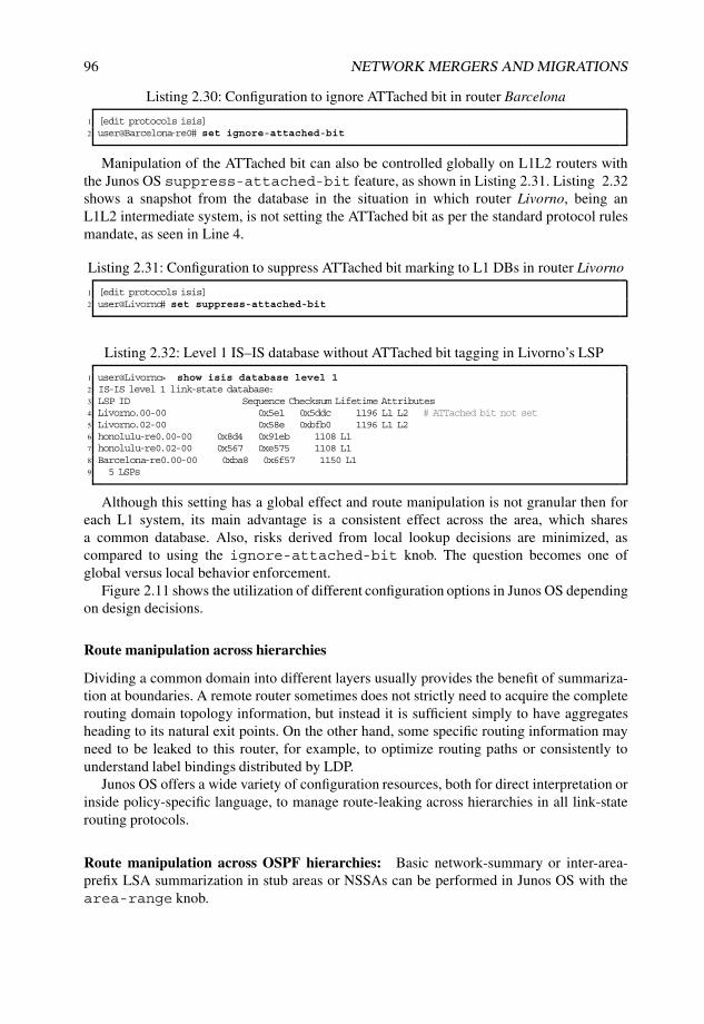
96 NETWORK MERGERS AND MIGRATIONS
Listing 2.30: Configuration to ignore ATTached bit in router Barcelona
1 [edit protocols isis]2 user@Barcelona-re0# set ignore-attached-bit
Manipulation of the ATTached bit can also be controlled globally on L1L2 routers withthe Junos OS suppress-attached-bit feature, as shown in Listing 2.31. Listing 2.32shows a snapshot from the database in the situation in which router Livorno, being anL1L2 intermediate system, is not setting the ATTached bit as per the standard protocol rulesmandate, as seen in Line 4.
Listing 2.31: Configuration to suppress ATTached bit marking to L1 DBs in router Livorno
1 [edit protocols isis]2 user@Livorno# set suppress-attached-bit
Listing 2.32: Level 1 IS–IS database without ATTached bit tagging in Livorno’s LSP
1 user@Livorno> show isis database level 12 IS-IS level 1 link-state database:3 LSP ID Sequence Checksum Lifetime Attributes4 Livorno.00-00 0x5e1 0x5ddc 1196 L1 L2 # ATTached bit not set5 Livorno.02-00 0x58e 0xbfb0 1196 L1 L26 honolulu-re0.00-00 0x8d4 0x91eb 1108 L17 honolulu-re0.02-00 0x567 0xe575 1108 L18 Barcelona-re0.00-00 0xba8 0x6f57 1150 L19 5 LSPs
Although this setting has a global effect and route manipulation is not granular then foreach L1 system, its main advantage is a consistent effect across the area, which sharesa common database. Also, risks derived from local lookup decisions are minimized, ascompared to using the ignore-attached-bit knob. The question becomes one ofglobal versus local behavior enforcement.
Figure 2.11 shows the utilization of different configuration options in Junos OS dependingon design decisions.
Route manipulation across hierarchies
Dividing a common domain into different layers usually provides the benefit of summariza-tion at boundaries. A remote router sometimes does not strictly need to acquire the completerouting domain topology information, but instead it is sufficient simply to have aggregatesheading to its natural exit points. On the other hand, some specific routing information mayneed to be leaked to this router, for example, to optimize routing paths or consistently tounderstand label bindings distributed by LDP.
Junos OS offers a wide variety of configuration resources, both for direct interpretation orinside policy-specific language, to manage route-leaking across hierarchies in all link-staterouting protocols.
Route manipulation across OSPF hierarchies: Basic network-summary or inter-area-prefix LSA summarization in stub areas or NSSAs can be performed in Junos OS with thearea-range knob.

LINK-STATE IGP MIGRATIONS 97
Default Junos OSbehavior
Default route installation in IS−IS
Remote orlocally set
ATTached bit?
Remote Local
No
’ignore−attached−bit’
Avoidlocally settingATTached bit?
No
Yes
Ignoreremotely set
ATTached bit?
Yes
’suppress−attached−bit’
Figure 2.11: IS–IS default route management depending on ATTached bit.
This functionality, illustrated in Listing 2.33, allows aggregation of internal area routeinformation from Type 1, Type 2, or Intra-Area-Prefix LSAs when generating summaries forthe backbone and other areas.
Listing 2.33: OSPFv2 and OSPFv3 area-range configuration for Summary and Inter-Area-Prefix LSAs in the backbone
1 [edit protocols ospf]2 user@Livorno# set area 0.0.0.3 area-range ?3 Possible completions:4 <area_range> Range to summarize routes in this area5 [edit protocols ospf3]6 user@Livorno# set area 0.0.0.3 area-range 192.168.200.0/24
Note that there is also an interesting derivative of this command in NSSAs. As ABRsin NSSAs are in charge of transforming Type 7 LSAs into Type 5, or Type 0x2007 intoType 0x4005 LSAs for the rest of the network, these boundaries also represent a realisticsummarization option and Junos OS offers the adequate resource for that by specifying thearea-range command inside the NSSA, as per Listing 2.34.
Listing 2.34: OSPFv2 and OSPFv3 NSSA area-range configuration for AS External LSAs inthe backbone
1 [edit protocols ospf]2 user@Livorno# set area 0.0.0.3 nssa area-range ?3 Possible completions:4 <area_range> Range to summarize NSSA routes in this area5 [edit protocols ospf3]6 user@Livorno# set area 0.0.0.3 nssa area-range 192.168.200.0/24
In both cases, an administrator can enforce exact matching for this summary by adding theexact knob after the area-range aggregate definition. Another available option is to define
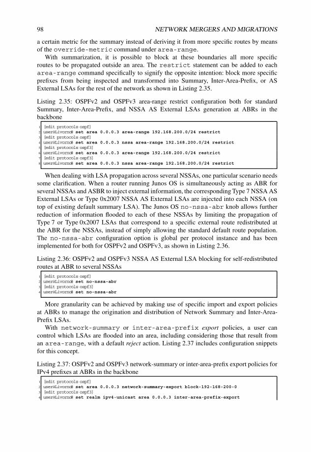
98 NETWORK MERGERS AND MIGRATIONS
a certain metric for the summary instead of deriving it from more specific routes by meansof the override-metric command under area-range.
With summarization, it is possible to block at these boundaries all more specificroutes to be propagated outside an area. The restrict statement can be added to eacharea-range command specifically to signify the opposite intention: block more specificprefixes from being inspected and transformed into Summary, Inter-Area-Prefix, or ASExternal LSAs for the rest of the network as shown in Listing 2.35.
Listing 2.35: OSPFv2 and OSPFv3 area-range restrict configuration both for standardSummary, Inter-Area-Prefix, and NSSA AS External LSAs generation at ABRs in thebackbone
1 [edit protocols ospf]2 user@Livorno# set area 0.0.0.3 area-range 192.168.200.0/24 restrict3 [edit protocols ospf]4 user@Livorno# set area 0.0.0.3 nssa area-range 192.168.200.0/24 restrict5 [edit protocols ospf3]6 user@Livorno# set area 0.0.0.3 area-range 192.168.200.0/24 restrict7 [edit protocols ospf3]8 user@Livorno# set area 0.0.0.3 nssa area-range 192.168.200.0/24 restrict
When dealing with LSA propagation across several NSSAs, one particular scenario needssome clarification. When a router running Junos OS is simultaneously acting as ABR forseveral NSSAs and ASBR to inject external information, the corresponding Type 7 NSSA ASExternal LSAs or Type 0x2007 NSSA AS External LSAs are injected into each NSSA (ontop of existing default summary LSA). The Junos OS no-nssa-abr knob allows furtherreduction of information flooded to each of these NSSAs by limiting the propagation ofType 7 or Type 0x2007 LSAs that correspond to a specific external route redistributed atthe ABR for the NSSAs, instead of simply allowing the standard default route population.The no-nssa-abr configuration option is global per protocol instance and has beenimplemented for both for OSPFv2 and OSPFv3, as shown in Listing 2.36.
Listing 2.36: OSPFv2 and OSPFv3 NSSA AS External LSA blocking for self-redistributedroutes at ABR to several NSSAs
1 [edit protocols ospf]2 user@Livorno# set no-nssa-abr3 [edit protocols ospf3]4 user@Livorno# set no-nssa-abr
More granularity can be achieved by making use of specific import and export policiesat ABRs to manage the origination and distribution of Network Summary and Inter-Area-Prefix LSAs.
With network-summary or inter-area-prefix export policies, a user cancontrol which LSAs are flooded into an area, including considering those that result froman area-range, with a default reject action. Listing 2.37 includes configuration snippetsfor this concept.
Listing 2.37: OSPFv2 and OSPFv3 network-summary or inter-area-prefix export policies forIPv4 prefixes at ABRs in the backbone
1 [edit protocols ospf]2 user@Livorno# set area 0.0.0.3 network-summary-export block-192-168-200-03 [edit protocols ospf3]4 user@Livorno# set realm ipv4-unicast area 0.0.0.3 inter-area-prefix-export

LINK-STATE IGP MIGRATIONS 99
5 block-192-168-200-06 [edit policy-options policy-statement block-192-168-200-0]7 user@Livorno# show8 term block-LSA {9 from {
10 route-filter 192.168.200.0/24 exact;11 }12 then reject;13 }14 term default {15 then accept;16 }
With network-summary or inter-area-prefix import policies, a user canmanage which LSAs learned from an area are used to contribute to the generation ofNetwork Summary and Inter-Area-Prefix LSAs to other areas. If a prefix is rejected by sucha policy, Junos OS still adds a route in the respective table, but it neither generates NetworkSummary or Inter-Area-Prefix LSAs though, nor does it use the route to activate a coveringarea-range. At a minimum, a more specific non-rejected prefix to issue an LSA mustexist for an area-range command to become active. Similar to other import policies inother stanzas, these policies default to an accept action, as indicated in Listing 2.38.
Listing 2.38: OSPFv2 and OSPFv3 network-summary or inter-area-prefix import policies forIPv4 prefixes at ABRs in the backbone
1 [edit protocols ospf]2 user@Livorno# set area 0.0.0.3 network-summary-import block-192-168-250-03
4 [edit protocols ospf3]5 user@Livorno# set realm ipv4-unicast area 0.0.0.3 inter-area-prefix-import6 block-192-168-250-07
8 [edit policy-options policy-statement block-192-168-250-0]9 user@Livorno# show
10 term block-LSA {11 from {12 route-filter 192.168.250.0/24 exact;13 }14 then reject;15 }
It is worth remarking here that the Junos OS policy language for such inter-area controlpolicies is not affected by the use of the existing from area or to area knobs. Policyconditions should match the route information existing on LSAs, but area-related policyconditions are designed to match route information for redistribution to other protocols oncethe route becomes active in the routing table. These area-related policies do not affect howLSA information is interpreted.
In addition to manipulating LSA transformation across hierarchies, Junos OS also allowsroute installation for all types of AS external LSAs to be blocked. AS external LSAsare bound to the reachability of the advertising router; they are not a cornerstone of theunderlying link-state protocol topology, but rather, provide external information anchoredat redistribution points. The Junos OS generic import acts on this type of information toreject or allow route installation in the routing table. Note that such import policies allowfiltering based on exact prefixes, external route types, interfaces, metrics, and tags, but theyhave a global protocol-wide scope, as depicted in Listing 2.39.

100 NETWORK MERGERS AND MIGRATIONS
Listing 2.39: OSPFv2 and OSPFv3 import policies for IPv4 prefixes from AS external LSAs
1 [edit protocols ospf]2 user@Livorno# set import block-192-168-150-03
4 [edit protocols ospf3]5 user@Livorno# set realm ipv4-unicast import block-192-168-150-06
7 [edit policy-options policy-statement block-192-168-150-0]8 user@Livorno# show9 term block-LSA {
10 from {11 route-filter 192.168.150.0/24 exact;12 }13 then reject;14 }
These policies do not lead to any kind of LSA manipulation, but just prevent specificroutes, present in the link-state database, from being installed in the routing table. Suchpolicies do not allow any specific route-handling, but instead re-evaluate the installation ofthe route in the routing table by considering the policy guidelines and then convey a simpleaccept or reject action.
Furthermore, these import policies apply only to AS external LSAs, which differ fromwhat a user would expect based on import policies from other protocols. The rationalefor this behavior is that information from internal LSA types is a substantial part of theunderlying IGP topology. Filtering internal LSAs fundamentally violates the principles of alink-state routing protocol and would establish the ideal conditions for creating routing loops.
Similarly, because AS external LSAs have domain-wide scope, it is futile to use anyfrom area or to area conditions inside any import policy for route installation, evenif the router is just attached to a single area, since LSA information inspected for routeinstallation is not characterized by any OSPF area at all.
Table 2.3 summarizes the available resources for LSA manipulation across OSPF hierar-chies.
Figure 2.12 includes a flowchart with design decisions based on available resources inJunos OS for route manipulation.
Route manipulation across IS–IS hierarchies By default, IS–IS has some specific ruleswith regard to route manipulation across hierarchies.
[RFC1195] defined a primary difference between internal routes (those belonging tothe same routing domain) and external routes (those injected from outside the domain),setting different TLVs and route priorities for them, such that internal route informationtakes precedence over external route information. [RFC1195] also defined the mechanism fordefault route installation to be based on detection of the ATTached bit set by L1L2 routers atlevel boundaries and following the shortest path to such area exit points.
[RFC2966] leveraged this constraint to allow external routes in a given L1 area and toallow arbitrary route-leaking from L1 to L2 areas. This original concept has been traditionallycompared to totally-stubby OSPF areas, or even totally-stubby NSSAs, when allowingexternal L1 routes inside the area. This distinction between internal and external routes ledto the following default route-leaking behavior:
• Internal L1 routes are propagated to L2 backbone.
• External L1 routes are not propagated to L2 backbone.

LINK-STATE IGP MIGRATIONS 101
Table 2.3 Resources available in Junos for route manipulation across OSPF hierarchies
Junos standalone resources Effect
area-range Network summary and Inter-area-prefixLSA summarization in stub or NSSA areas
area-range exact Exact matching enforced for routeaggregation
area-range restrict Restrict prefix from summarization actionand population in backbone and other areas
import Route installation control in OSPFv2 andOSPFv3 AS external LSAs
inter-area-prefix-export Granular control in OSPFv3 of LSAgeneration into areas by means of policies
inter-area-prefix-import Granular control in OSPFv3 of LSAseligible for translation into inter-area-prefix LSAs by means of policies
network-summary-export Granular control in OSPFv2 of LSAgeneration into areas by means of policies
network-summary-import Granular control in OSPFv2 of LSAs eligi-ble for translation into Network SummaryLSAs by means of policies
no-nssa-abr Further LSA reduction when being simul-taneously ABR and ASBR for NSSAs
nssa area-range Aggregation when transforming Type 7LSAs into Type 5, or Type 0x2007 intoType 0x4005 LSAs
• Internal L2 routes are not propagated to L1 Area.
• External L2 routes are not propagated to L1 Area.
However, this traditional classification was soon made obsolete. Modern networks neededeven more route manipulation flexibility and metric space was scarce with the originalold-style TLVs, which had a maximum value of 63. [RFC3784] defined extensions forTraffic-Engineering (TE) and in the process added two modern TLVs to cope with the TLVlength requirements, namely TLV 22 Extended IS Reachability and TLV 135 Extended IPReachability.
In addition to removing the restriction on the length of the metric field, [RFC3784]deprecated the differentiation between internal and external metrics. For practical reasons,configuring wide metrics also leverages the internal–external distinction for prefixes injectedinto a given system. With no external routes, the default propagation rules are simplified:
• Wide-metrics L1 routes are propagated to L2 backbone.
• Wide-metrics L2 routes are not propagated to L1 Area.

102 NETWORK MERGERS AND MIGRATIONS
Default Junos OSbehavior
Route manipulation across OSPF hierarchies
Local routeinstallation or
LSA translation?
Local route LSA translation
No
’import’
Prefixmanipulationon incoming
LSAs?
Avoid routeinstallationfrom LSA?
Yes
Prefixmanipulationfor outgoing
LSAs?
No
No
’network−summary−import’
’inter−area−prefix−import’
Standard LSA translation (OSPFv2)
StandardLSA translation (OSPFv3)
’(nssa) area−range’Prefix aggregation
Prefix suppresion
’(nssa) area−range restrict’
’network−summary−export’
’inter−area−prefix−export’
Standard LSA translation (OSPFv2)
Standard LSA translation (OSPFv3)
Figure 2.12: OSPF route manipulation across hierarchies.
While keeping all this in mind, an administrator also needs to take into account supportfor the particular metric style used in a network. A transitional stage may be needed, inwhich systems inject both old-style and new-style TLVs, so that systems can understandeither narrow metrics or wide metrics.
Junos OS accepts both styles, and by default, advertises both styles as well. Sending andaccepting both styles is a realistic scenario for a transitional model. If this is not the desiredbehavior, the wide-metrics-only command prevents the generation of old-style TLVsand issues only new-style TLVs on a per-level basis. Note that including this keyword notonly has the expected effect of expanding the metric size, but it can also indirectly modifyroutes leaked to L2 backbone by removing the external distinction.
As compared to OSPF, Junos OS has not implemented specific knobs for route summariza-tion across levels in IS–IS precisely because leaking can be controlled flexibly by policies.From this perspective, the use of Junos OS tailored aggregate or generate routes can perfectlyfit the needs for summarization, being created upon only when more specific prefixes exist,and being perfectly eligible for policy matching conditions.
Junos OS policy language also allows definition of specific policies to be used for route-leaking between levels and in both directions. Specific keywords such as from level andto level are provided to match criteria precisely in a given policy. Note that according tothe definition of narrow metrics, routes installed at each level are placed into substantiallydifferent databases (except for default internal route-leaking from Level 1 to Level 2, whichinjects information in both). Additional route population can be defined with fine-grainedcontrol to tailor additional inter-level leaking. The example policy in Listing 2.40 illustratesa very simplistic policy to inject all active IS–IS Level 2 prefixes that match host loopbackaddresses into directly attached Level 1 areas. Such a policy would just need to be addedto the standard IS–IS export policy chain. Similar policies could be defined to overcomestandard route population limitations across levels.

LINK-STATE IGP MIGRATIONS 103
Listing 2.40: Using level policy keyword to leak IS–IS level 2 routes into level 1 areas
1 [edit policy-options policy-statement Leak-L2-to-L1]2 user@Livorno# show3 term leak-L2 {4 from {5 level 2;6 route-filter 0.0.0.0/0 prefix-length-range /32-/32;7 }8 to level 1;9 then accept;
10 }
Table 2.4 summarizes these available resources for route manipulation across IS–IShierarchies.
Table 2.4 Resources available in Junos for route manipulation across IS–IS hierarchies
Junos standalone resources Effect
from level Policy matching criterion on routes to beexported from a certain level
to level Policy matching criterion on routes to beexported to a certain level
wide-metrics-only Enforce metric expansion with newerstyle TLVs and remove internal/externaldistinction
Figure 2.13 describes the utilization of Junos OS configuration options related with routemanipulation across IS–IS hierarchies.
Point-to-point setups for merging areas
A traditional approach for artificially linking distant network segments has been to establishvirtual constructs that are mapped over the existing physical topology, so as to allow indirectstitching of areas or sites. Fairly common benefits of using such resources in link-staterouting-protocol-based networks are routing policy enforcement, because intra-area routesare always preferred to inter-area routes.
Such point-to-point virtual setups are usually discouraged by many network designers.Every time a routing topology differs from the physical link topology, operational andtroubleshooting challenges and potential divergence issues certainly increase. While thesesetups can sometimes be the best fit for a transitional period or migration step, they areusually not considered the basis of a good design.
OSPF virtual-links: [RFC2328] initially defined virtual links as a method for stitchingtogether a partitioned backbone.
Such unnumbered point-to-point links can be established between backbone routers usinga non-backbone area for transport, thus expanding Area 0 beyond its natural boundaries.Routing information for virtual links is included in the Type 1 Router LSAs, which carry a
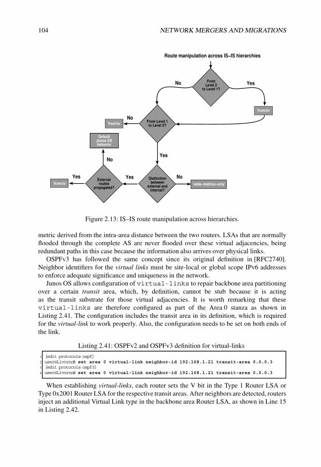
104 NETWORK MERGERS AND MIGRATIONS
Default Junos OSbehavior
Route manipulation across IS−IS hierarchies
From Level 2
to Level 1?
No Yes
From Level 1to Level 2?
Yes
’from/to’
Distinctionbetween
external andinternal?
No’from/to’
YesExternalroutes
propagated?
Yes
No
’from/to’
No
’wide−metrics−only’
Figure 2.13: IS–IS route manipulation across hierarchies.
metric derived from the intra-area distance between the two routers. LSAs that are normallyflooded through the complete AS are never flooded over these virtual adjacencies, beingredundant paths in this case because the information also arrives over physical links.
OSPFv3 has followed the same concept since its original definition in [RFC2740].Neighbor identifiers for the virtual links must be site-local or global scope IPv6 addressesto enforce adequate significance and uniqueness in the network.
Junos OS allows configuration of virtual-links to repair backbone area partitioningover a certain transit area, which, by definition, cannot be stub because it is actingas the transit substrate for those virtual adjacencies. It is worth remarking that thesevirtual-links are therefore configured as part of the Area 0 stanza as shown inListing 2.41. The configuration includes the transit area in its definition, which is requiredfor the virtual-link to work properly. Also, the configuration needs to be set on both ends ofthe link.
Listing 2.41: OSPFv2 and OSPFv3 definition for virtual-links
1 [edit protocols ospf]2 user@Livorno# set area 0 virtual-link neighbor-id 192.168.1.21 transit-area 0.0.0.33 [edit protocols ospf3]4 user@Livorno# set area 0 virtual-link neighbor-id 192.168.1.21 transit-area 0.0.0.3
When establishing virtual-links, each router sets the V bit in the Type 1 Router LSA orType 0x2001 Router LSA for the respective transit areas. After neighbors are detected, routersinject an additional Virtual Link type in the backbone area Router LSA, as shown in Line 15in Listing 2.42.

LINK-STATE IGP MIGRATIONS 105
Listing 2.42: OSPF Router LSA including Virtual Links
1 user@Livorno> show ospf database extensive router lsa-id 192.168.1.6 area 02
3 OSPF link state database, Area 0.0.0.04 Type ID Adv Rtr Seq Age Opt Cksum Len5 Router *192.168.1.6 192.168.1.6 0x80000961 219 0x22 0x4595 1326 bits 0x1, link count 97 <...>8 id 192.168.1.6, data 255.255.255.255, Type Stub (3)9 TOS count 0, TOS 0 metric 0
10 <...>11 id 192.168.1.4, data 172.16.1.38, Type PointToPoint (1)12 TOS count 0, TOS 0 metric 113 id 172.16.1.36, data 255.255.255.252, Type Stub (3)14 TOS count 0, TOS 0 metric 115 id 192.168.1.21, data 172.16.1.89, Type Virtual (4) # Virtual Link Type16 TOS count 0, TOS 0 metric 117 Gen timer 00:00:1318 Aging timer 00:56:2119 Installed 00:03:39 ago, expires in 00:56:21, sent 00:03:37 ago20 Last changed 00:06:49 ago, Change count: 31, Ours
Junos OS identifies such virtual-links as legitimate neighbor relationships and displaysthem in a similar fashion, as shown in Listing 2.43.
Listing 2.43: OSPF Virtual Link neighbor
1 user@Livorno> show ospf neighbor detail 172.16.1.902 Address Interface State ID Pri Dead3 172.16.1.90 vl-192.168.1.21 Full 192.168.1.21 0 394 Area 0.0.0.0, opt 0x42, DR 0.0.0.0, BDR 0.0.0.05 Up 00:05:08, adjacent 00:05:076 172.16.1.90 ge-1/3/0.0 Full 192.168.1.21 128 347 Area 0.0.0.3, opt 0x42, DR 172.16.1.89, BDR 172.16.1.908 Up 00:16:53, adjacent 00:16:53
Viewed another way, such virtual relationships are merely floating connections that froma TE perspective rely on the definition of parameters in the transit area. They do not activelyforward any kind of traffic, but act simply as control-plane connections based on recursiveroute resolution. When inspecting Opaque LSAs issued for virtual links in the backbonearea, no bandwidth, metric, or admin-group attributes are associated with them; that is, noLink TLVs but just Router Address TLVs are present, as defined in [RFC3630]. Because theOpaque LSAs lack these attributes, the virtual links cannot be manipulated for TE purposes,as shown in Listing 2.44.
Listing 2.44: OSPF Opaque LSA referring to a Virtual Link
1 user@Livorno> show ospf database opaque-area area 0 extensive2 advertising-router 192.168.1.213
4 OSPF link state database, Area 0.0.0.05 Type ID Adv Rtr Seq Age Opt Cksum Len6 OpaqArea 1.0.0.1 192.168.1.21 0x80000002 285 0x22 0xfe30 287 Area-opaque TE LSA8 RtrAddr (1), length 4: 192.168.1.219 Aging timer 00:55:15
10 Installed 00:04:42 ago, expires in 00:55:15, sent 00:04:40 ago11 Last changed 00:09:09 ago, Change count: 1

106 NETWORK MERGERS AND MIGRATIONS
Point-to-point tunnels: Another way to bind separate network regions is based on tunnelconstructs between specific end points in the topology.
Such point-to-point tunnels must be able to transport the necessary types of traffic andprotocol and must be correctly sized to accomplish this virtual transport, especially in termsof bandwidth and Maximum Transmission Unit (MTU).
Although point-to-point tunnels can be treated from a protocol perspective as anothertopology link, their establishment is dependent on end-point reachability and routingvariations between both sides. This requirement poses the additional challenge of ensuringthat routing protocols can run properly over the setup (for instance, support for CLNP orMPLS traffic) and that they cannot easily overwhelm existing bandwidth limitations acrossthe path.
A common concern is the feasible Maximum Transmission Unit (MTU) to apply over thetunnel. Even though arbitrary MTU values can be configured at both ends of the tunnel, thisconstruct requires additional encapsulation on top of original data. As a result, MTU limitson the underlying physical topology can be reached when a tunnel is established on top of it.
Another common problem is the potential for a chicken-and-egg situation, where point-to-point tunnels are established between real end points but enabling routing protocols overthese constructs leads to real end-point reachability over the virtual constructs because ofmetric election or area segregation. In this case, virtual abstractions alter the perception ofthe real network topology.
Routing platforms may consider several dependencies and need specific requirements toestablish point-to-point tunnels. Junos OS Release Notes include descriptions for differenttypes of point-to-point tunnel and resource needed in each Juniper Networks platform.
For the purpose of enabling a virtual routing topology over a network, Generic RoutingEncapsulating (GRE) or IP-over-IP point-to-point tunnels are the simplest fits. These typesof tunnel also support other protocol families, such as MPLS or IPv6, to be transported overan agnostic underlying IPv4 substrate that establishes an adequate vehicle for migrations.From a TE perspective, such connections are treated as standard logical interfaces with therespective attributes and TLVs.
However, these kinds of tunnel lead to an additional degree of abstraction above thephysical link subset. Although they are sometimes the only way to achieve particulardesign goals, they are certainly not encouraged as a best practice in a permanent networkimplementation because of all the operational headaches they can introduce and because ofthe lack of transparency in the design.
MPLS Forwarding Adjacencies: Junos OS supports the use of RSVP-based LSPs tocreate virtual forwarding adjacencies both for OSPFv2 and IS–IS.
The basic idea behind this concept is to advertise such LSPs into link-state protocols aspoint-to-point links so that they can be used in SPF calculations at nodes other than the headend, as opposed to plain IGP shortcuts, in which the only node that knows about the existenceof such LSPs is the LSP ingress end.
The configuration steps in Junos OS include a prior definition of the RSVP LSP andan activation of the LSP advertisement under the corresponding IGP stanza, as shownin Listing 2.45. Note that when an LSP stretches across two or more areas, the LSPconfiguration needs to include the no-cspf keyword to trigger proper RSVP signaling andto avoid local path prior calculation considering the TED.

LINK-STATE IGP MIGRATIONS 107
Listing 2.45: Simple definition of LSP advertisement into OSPFv2 or IS–IS
1 [edit protocols mpls]2 user@Livorno# set label-switched-path Livorno-Honolulu no-cspf to 192.168.1.213 [edit protocols ospf]4 user@Livorno# set area 0 label-switched-path Livorno-Honolulu5 [edit protocols isis]6 user@Livorno# set label-switched-path Livorno-Honolulu
Although Junos OS does not treat these LSPs as virtual interfaces, a valid alternative is tostitch together specific domain end points from an IGP perspective to replicate a particularbehavior. Note that Hello messages are not sent over the LSP, and no information floodingtakes place over them. These LSPs are virtual structures just for forwarding purposes, buttheir information is included in the respective protocol constructs. When comparing MPLSforwarding adjacencies with the OSPF virtual link setup discussed in the previous section onPage 103, if an RSVP-TE LSP is configured between the same end points, a point-to-pointand a stub link type for the LSP remote end are included in the Type 1 Router LSAs, as shownin Listing 2.46. From a TE perspective, this virtual construct has no specific Opaque LSAs.The IS–IS behavior is completely analogous. IS–IS represents this link as another virtual ISneighbor lacking specific TE sub-TLVs or other kinds of similar information, as shown inListing 2.47.
Listing 2.46: OSPFv2 Router LSA including forwarding adjacency link information
1 user@Livorno> show ospf database router extensive lsa-id 192.168.1.6 area 02
3 OSPF link state database, Area 0.0.0.04 Type ID Adv Rtr Seq Age Opt Cksum Len5 Router *192.168.1.6 192.168.1.6 0x8000096a 61 0x22 0x4e89 1446 bits 0x1, link count 107 id 192.168.1.21, data 128.0.0.3, Type PointToPoint (1) # LSP advert P2P link8 TOS count 0, TOS 0 metric 19 id 192.168.1.21, data 255.255.255.255, Type Stub (3) # LSP advert stub link
10 TOS count 0, TOS 0 metric 111 id 172.16.100.0, data 255.255.255.0, Type Stub (3)12 TOS count 0, TOS 0 metric 113 <...>14 id 192.168.1.6, data 255.255.255.255, Type Stub (3)15 TOS count 0, TOS 0 metric 016 <...>17 Gen timer 00:48:5818 Aging timer 00:58:5819 Installed 00:01:01 ago, expires in 00:58:59, sent 00:01:01 ago20 Last changed 00:01:01 ago, Change count: 35, Ours
Listing 2.47: IS–IS Level 2 LSP including forwarding adjacency link information
1 user@Livorno> show isis database Livorno.00-00 level 2 extensive2 IS-IS level 2 link-state database:3
4 Livorno.00-00 Sequence: 0x4df9, Checksum: 0x936d, Lifetime: 607 secs5 IS neighbor: Skopie.00 Metric: 6436 IS neighbor: Havana.00 Metric: 6437 IS neighbor: honolulu-re0.00 Metric: 108 IP prefix: 172.16.1.32/30 Metric: 643 Internal Up9 IP prefix: 172.16.1.36/30 Metric: 643 Internal Up
10 IP prefix: 192.168.1.6/32 Metric: 0 Internal Up11 <...>12 TLVs:13 Area address: 49.0002 (3)14 Area address: 49.0003 (3)

108 NETWORK MERGERS AND MIGRATIONS
15 Speaks: IP16 Speaks: IPV617 IP router id: 192.168.1.618 IP address: 192.168.1.619 Hostname: Livorno20 IS extended neighbor: Skopie.00, Metric: default 64321 IP address: 172.16.1.3422 Neighbor’s IP address: 172.16.1.3323 Local interface index: 82, Remote interface index: 7224 Current reservable bandwidth:25 <...>26 IS extended neighbor: Havana.00, Metric: default 64327 IP address: 172.16.1.3828 Neighbor’s IP address: 172.16.1.3729 Local interface index: 83, Remote interface index: 7330 Current reservable bandwidth:31 <...>32 IS extended neighbor: honolulu-re0.00, Metric: default 10 # IS-neighbor over LSP33 IP extended prefix: 192.168.1.6/32 metric 0 up34 IP extended prefix: 172.16.1.36/30 metric 643 up35 IP extended prefix: 172.16.1.32/30 metric 643 up36 No queued transmissions
Junos OS displays such virtual adjacencies in a similar fashion, including the referencefor the advertised LSP, as shown in Listing 2.48 for OSPFv2 and 2.49 for IS–IS. Note thatfor one of such virtual adjacencies to function, bidirectional LSP reachability is required.
Listing 2.48: OSPFv2 neighbor information including forwarding adjacency
1 user@Livorno> show ospf neighbor 192.168.1.21 extensive2 Address Interface State ID Pri Dead3 192.168.1.21 Livorno-Honolulu Full 192.168.1.21 0 0 # Interface field
referring to LSP4 Area 0.0.0.0, opt 0x0, DR 0.0.0.0, BDR 0.0.0.05 Up 00:17:006 172.16.1.90 ge-1/3/0.0 Full 192.168.1.21 128 367 Area 0.0.0.3, opt 0x42, DR 172.16.1.89, BDR 172.16.1.908 Up 02:44:40, adjacent 02:44:40
Listing 2.49: IS–IS adjacency information including forwarding adjacency
1 user@Livorno> show isis adjacency extensive honolulu-re02 honolulu-re03 Interface: Livorno-Honolulu, Level: 2, State: Up, Expires in 0 secs # Interface field referring to
LSP4 Priority: 0, Up/Down transitions: 1, Last transition: 00:16:37 ago5 Circuit type: 2, Speaks: IP6 Topologies: Unicast7 Restart capable: No, Adjacency advertisement: Advertise8 IP addresses: 192.168.1.219 Transition log:
10 When State Event Down reason11 Sun Feb 15 20:07:22 Up Seenself12
13 honolulu-re014 Interface: ge-1/3/0.0, Level: 1, State: Up, Expires in 8 secs15 Priority: 64, Up/Down transitions: 1, Last transition: 08:58:41 ago16 Circuit type: 1, Speaks: IP, IPv6, MAC address: 0:17:cb:d3:2f:1617 Topologies: Unicast18 Restart capable: Yes, Adjacency advertisement: Advertise19 LAN id: honolulu-re0.02, IP addresses: 172.16.1.9020 Transition log:21 When State Event Down reason22 Sun Feb 15 11:25:18 Up Seenself

LINK-STATE IGP MIGRATIONS 109
Because these LSPs inject routing information in the standard IGP database, LSPs areavailable to transport not only MPLS or TE aware applications, but also all kinds of transporttraffic, including plain IPv4. This behavior adds opacity to the setup in the sense that theunderlying topology is not visible in a straightforward manner for troubleshooting andoperational purposes, but it can certainly fulfill requirements for certain migrations or setups.
A final consideration is that for a forwarding adjacency to work properly, LSPs must beestablished in both directions between both ends. Junos OS does not enforce using a singleLSP for return traffic in a plain forwarding adjacency; more than one LSP can share the loadfor revertive reachability, as would happen with standard MPLS traffic. This requirementmeans that LSPs need to be properly conceived and configured at the design stage to ensureproper LSP pairing for both directions.
This traditional plain forwarding adjacency concept has further evolved with [RFC4203],[RFC5305], and [RFC4206] so that this information is simply placed into the TED and isthen used to construct LSP hierarchies.
2.2 Link-state IGP Domain Migrations
Another ongoing discussion in the internetworking world has been if OSPF or IS–IS wouldbe the most convenient link-state IGP for core deployments. Many cross-analyses have beendone in the networking industry about whether OSPF or IS–IS should be preferred undersome circumstances, because both protocols are parallel approaches to running link-staterouting from different origins.
The foundations for both protocols are based on common link-state concepts despite thefact that OSPF runs over IP and IS–IS over data link CLNP. In both protocols, an adjacency iscreated to maintain a neighbor relationship based on agreed parameters and these adjacenciesbuild up a common topology to be considered both for path calculation and informationflooding. Routing information is collected into a link-state database, and SPF calculationsusing the Dijkstra algorithm are carried out based on these data.
The terminology in each protocol is indeed different, but the purpose of many of the datastructures and router roles is the same. Discussions about formalisms and acronyms apart,certainly some technical features that one or the other protocol presents exist, as well assome behaviors that can be considered as drawbacks or as advantages in some topologies.
2.2.1 Considerations for a link-state IGP migration
Link-state information chunks are encapsulated in the IS–IS Link-State PDUs (LSPs) whichare directly flooded as complete data structures, whereas in OSPF, LSAs are grouped andencapsulated in Link-State Update packets before propagation. IS–IS TLVs inside an LSPwould be the equivalent data structures to OSPF LSAs. This means that while information istranslated from one LSA format to another in an OSPF ABR or ASBR, the same IS–IS TLVtypes are used in both L1 and L2 LSPs.
Another well-known difference is area definition and separation: IS–IS considers a Level 2as a contiguous subdomain of backbone routers, independent of the area identifier included ineach Net-ID, whereas OSPF requires a backbone with all adjacencies inside the same Area 0.Area boundaries are therefore different in the sense that an IS–IS L1L2 router is considered aspart of the backbone and area edge, and can indistinctly establish both L1 and L2 adjacencies

110 NETWORK MERGERS AND MIGRATIONS
over the same physical link, but OSPF used to define an adjacency for each logical link andhierarchical separation on each ABR. [RFC5185] proposes a new approach to run multi-areaadjacencies in OSPF, allowing a single physical point-to-point link to be shared by multipleareas, thus changing this traditional association.
Therefore, Intermediate Systems in Level 2 do not need to have a matching area identifier,and they automatically set the ATTached bit in their L1 LSPs to indicate backbonereachability. [RFC3509] describes different behaviors of an ABR performing LSA generationor transformation, focusing on whether an active adjacency is required in Area 0. Dependingon the router operating system, this concept for backbone detection would be another factor toconsider in a migration. Junos OS implements active backbone support for ABRs, meaningthat an active backbone connection is checked in addition to the ABR status to performABR functionality, such summarizing LSAs in both directions, or advertising or withdrawingsummary LSAs into stub areas and NSSAs.
IS–IS L1 areas traditionally were equivalent to OSPF totally stubby areas, as they have,by default, no visibility on backbone prefixes or routes from other areas, apart from a defaultroute installed based on detection of the ATTached bit, and because external prefixes arenot populated to Layer 2 by default. However, route-leaking policies and wide metrics canchange information distribution in both directions and allow greater flexibility in prefixpopulation. While most routing vendors also include similar route-leaking capability at OSPFABRs, certain types of area mandate LSA population or blocking. Care must be taken whenmigrating IS–IS to OSPF areas, not only when adapting redistribution policies but whenelecting the appropriate type of OSPF area.
When migrating area or system identification from one protocol to the other, numberingschemes must be adapted as well. Area identification is a 32-bit number in OSPF (exactly thesame size as the Router ID), but IS–IS uses an Area ID that can vary from 1 to 13 bytes anda System ID that is usually 6 bytes long, both inside the Net-ID.
OSPF supports broadcast, point-to-point, point-to-multipoint, and NBMA media, whereasIS–IS only considers broadcast and point-to-point link types when setting up adjacencies.Migrating from one protocol to the other may also require link transformation or adaption.
Adjacency establishment is also slightly different between the two protocols. Apart fromusing different timer values, most OSPF hello packet fields need to match for participatingneighbors (Area ID, timers, authentication, network mask, options), and there is a DesignatedRouter (DR) and Backup Designated Router (BDR) election in broadcast media. IS–IS justelects a single Designated Intermediate System (DIS) in broadcast links, and some of thehello fields do not agree, such as hello and dead intervals. The DIS role is also preemptive,whereas OSPF DR and BDR are not.
In OSPF broadcast media, an adjacency is formed with a DR and BDR, but IS–IS createsa full adjacency mesh among participating Intermediate Systems on each level.
Likewise, neighbor discovery in IS–IS can happen at different levels, except in point-to-point links, which have a single Point-to-Point Hello PDU for both levels. This meansthat some of the parameters required to build up an adjacency need to match in both levels,particularly authentication settings.
Because IS–IS is not based on IP, it requires a different inherent mechanism to performsegmentation derived from an initial discovery based on padding hello messages with aso-called TLV 8 Padding. OSPF is based on IP, which directly handles fragmentation andreassembly. [RFC2328] defines an additional check based on the Interface MTU field of

LINK-STATE IGP MIGRATIONS 111
Database Description Packets, so that if this value is larger than the IP datagram size that therouter can accept on the receiving interface without fragmentation, the Database DescriptionPacket is rejected and the adjacency does not reach FULL state. Router vendors implementdifferent padding mechanisms with hello messages to confirm an MTU size. An MTUmismatch usually prevents adjacency formation as the Database Description or Link-stateUpdate packets cannot be properly flooded in both directions.
OSPF synchronizes databases with a master and slave election, exchanging those DatabaseDescription packets with LSA headers and Link-state Requests and Updates to update eachrouter’s topological information. IS–IS considers a much simpler and regular synchronizationprocess, where Complete Sequence Number PDUs (CSNPs) are regularly sent and particularinformation is retrieved via Partial Sequence Number PDUs (PSNPs). [RFC4811] advocatesa new out-of-band Link State Database (LSDB) resynchronization for OSPF to allow thedatabase to be refreshed without topological changes or tearing down adjacencies.
Regular refreshing of information is also handled differently in both protocols. In additionto using timer counters in opposite directions, the maximum link-state information lifetime(MaxAge parameter) is not configurable in OSPF but its equivalent parameter can be changedin IS–IS. Configuring this value can notably help fine-tune background refresh activities.
Metrics are also calculated in different ways. While both protocols allow particular metricson a per link basis and most operating systems have extended the concept of having areference bandwidth for link calculation from OSPF to IS–IS automatically to derive metricsdepending on link rates, IS–IS has introduced the concept of wide metrics, which extendsthe corresponding field up to 32 bits and automatically allows prefix distribution acrossthe complete domain. Wide metrics no longer consider a distinction between internal andexternal routes. OSPFv2 Type 1 LSAs include a 16-bit metric field, and Types 3, 4, 5, and 7LSAs reserve 24 bits.
Because of how LSAs are constructed, OSPF has traditionally required that all neighborsneed to understand newer LSA extensions. [RFC3630] and [RFC4970] add a certainflexibility by including TLV coding in Type 10 Opaque LSAs or Type 12 RI OpaqueLSAs for OSPFv2 and OSPFv3, potentially allowing future extensibility. However, IS–IS TLVs were originally fashioned in a nested hierarchy and for flexible and transparentextension introduction, in which only unknown TLVs may be discarded by neighbors, notcomplete LSPs.
The virtual link concept was originally described in [RFC1131] as a way to avoidbackbone fragmentation. Although [ISO10589] also included a similar concept for IS–ISpartition repair, most routing vendors have not implemented it. It is considered a best practicejust to define virtual links as temporary workarounds to grant Area 0 extensibility. If OSPFvirtual links need to be migrated to IS–IS, this transition requires full backbone connectivityor use of a similar point-to-point construct.
IS–IS also supports a particular behavior to avoid routing transit traffic over the platformwhen setting the Overload bit in the LSPs. In this state, intermediate systems signal a lackof transit capability to the rest of the area. [RFC3137] defines a similar behavior for OSPF,in which the cost for all non-stub links is set to infinity. This same concept to advertisemaximum metrics has also been extrapolated to Junos OS IS–IS in the sense that transittraffic is not directly prohibited, but rather, remains valid as an alternative path with maximumpossible metric. Although the Overload bit was originally conceived to block transit routingas the result of some critical situation, it can also be considered a best practice to set it during
112 NETWORK MERGERS AND MIGRATIONS
intrusive operations on a transit router to minimize service downtime and transit traffic loss.Regardless, correct portability needs to be ensured when moving from one link-state IGP toanother.
[RFC2973] standardizes the concept of an IS–IS mesh group by defining restrictedflooding topologies as a subset of the full IS–IS domain topology. Highly meshed topologiescan lead to excessive information flooding, provided that incoming routing information isreflooded by default on all other outgoing interfaces. While initially this can be seen asa resilient behavior, it generates a considerable amount of additional traffic in sufficientlyredundant setups. The mesh group concept constrains flooding so that LSPs can be forwardedwith enough guarantees, but redundant background noise can be suppressed from thenetwork if the corresponding design premises are taken into account. Note that OSPF hasno equivalent concept, which can present a migration drawback.
IPv6 support is also completely different in both protocols. [RFC2740] defines a newerversion 3 of OSPF protocol for IPv6 support. The result is that a new protocol flavor needsto be configured with an overlay model when compared with traditional OSPF version 2.OSPFv3 inherits most protocol concepts from version 2, but also defines new data structuresand LSAs, requiring a separate database. On the other hand, [RFC5308] defines new IPv6specific TLVs to be additionally injected in standard IS–IS LSPs. This design ensures softintegration of an IPv6 topology, and no other additional protocol features or databases arerequired.
TE extensions are supported equally on both link-state IGPs. [RFC3630] redefines theType 10 Opaque LSA to flood TE information. Interestingly, this Opaque LSA includesa Router TLV that [RFC3630] Section 2.4.1 included so that if IS–IS is also active in thedomain, the address referred by this TLV can be used to compute the mapping between theOSPF and IS–IS topologies. There is another Link TLV included in this Opaque LSA, whichcovers the following sub-TLVs:
• (Sub-TLV 1) Link type (1 byte);
• (Sub-TLV 2) Link ID (4 bytes);
• (Sub-TLV 3) local interface IP address (4 bytes);
• (Sub-TLV 4) remote interface IP address (4 bytes);
• (Sub-TLV 5) TE metric (4 bytes);
• (Sub-TLV 6) maximum bandwidth (4 bytes);
• (Sub-TLV 7) maximum reservable bandwidth (4 bytes);
• (Sub-TLV 8) unreserved bandwidth (32 bytes);
• (Sub-TLV 9) administrative group (4 bytes).
[RFC3784] is the counterpart TE standard for IS–IS. It defines a new TLV 134 TE routerID, that uniquely identifies each router in the TED with a stable identifier and it expands TLV22 Extended IS Reachability and TLV 135 Extended IP Reachability with newer sub-TLVstructures and modified fields that convey TE information.
The TLV 22 Extended IS Reachability is expanded with newer sub-TLV structures thataggregate TE information as follows:

LINK-STATE IGP MIGRATIONS 113
• (Sub-TLV 3) administrative group (4 bytes);
• (Sub-TLV 6) IPv4 interface address (4 bytes);
• (Sub-TLV 8) IPv4 neighbor address (4 bytes);
• (Sub-TLV 9) maximum link bandwidth (4 bytes);
• (Sub-TLV 10) reservable link bandwidth (4 bytes);
• (Sub-TLV 11) unreserved bandwidth (32 bytes);
• (Sub-TLV 18) TE default metric (3 bytes);
• (Sub-TLV 250-254) reserved for Cisco-specific extensions;
• (Sub-TLV 255) reserved for future expansion.
Even though sub-TLV 18 TE Default metric has been referred to above as being 3 octetslong, the idea is to preclude overflow within a TE SPF implementation, in which all metricsgreater than or equal to a maximum path metric value are considered to have that maximummetric. The rationale is to select a value such that maximum path metric plus a single linkmetric does not overflow the number of bits for internal metric calculation, which is also32 bits long. In this way, this IS–IS sub-TLV remains compatible with the OSPF sub-TLV 5TE metric, which is 4 octets long.
[RFC3784] also expands the TLV 135 Extended IP Reachability with up to 32-bit metricfields and adds a new bit to indicate that a prefix has been redistributed down in the hierarchy.
OSPF sub-TLV 9 administrative group allows setting specific groups for links with up to 4octets, which is the same length from the IS–IS sub-TLV 3 administrative group value field.Migrating administrative group values from one protocol to the other is transparent in termsof length.
Therefore, to populate a joint TED in an overlay model with OSPF and IS–IS, the OSPFRouter TLV from the Type 10 Opaque LSA and the IS–IS TLV 134 TE router ID must includethe same Router ID value and link TE metrics must be equivalent.
Another commonality is the ability to support forwarding adjacencies by the twoprotocols. Plain forwarding adjacencies have been discussed previously in the case of usingRSVP-TE LSP infrastructure to virtualize a point-to-point link available for calculation ofthe IGP shortest path. The rationale here is to guarantee bidirectional reachability and reusethese adjacencies between Label-Switched Routers (LSRs) to be available for IGPs as virtualconnections.
This traditional concept evolved further with GMPLS TE procedures as defined in[RFC4203], [RFC5305], and [RFC4206] to advertise these LSPs (the so-called ForwardingAdjacency LSPs or FA-LSPs) as TE links into the same instance of ISIS or OSPF that wasused to create the LSP. In this environment, the FA-LSPs represent TE links between twoGMPLS nodes whose path is established in the same instance of the GMPLS control plane.Having this virtualization for FA-LSPs available in the TED for path calculations allows anRSVP hierarchical model with different LSP regions in which specific FA-LSPs could beelected as hops in RSVP LSP path computations.
[RFC4203] defines newer sub-TLVs to be added to OSPF Opaque LSA Link TLVs:

114 NETWORK MERGERS AND MIGRATIONS
• (Sub-TLV 11) Link Local/Remote Identifiers (8 bytes);
• (Sub-TLV 14) Link Protection Type (4 bytes);
• (Sub-TLV 15) Interface Switching Capability Descriptor (variable);
• (Sub-TLV 16) Shared Risk Link Group (variable).
Similarly, [RFC5305] conceives parallel mechanisms and information structures for IS–IS. Although Shared Risk Link Group information is defined as a new TE TLV 138 SharedRisk Link Group, all other bits are defined as sub-TLVs for the TLV 22 Extended ISReachability:
• (Sub-TLV 4) Link Local/Remote Identifiers (8 bytes);
• (Sub-TLV 20) Link Protection Type (2 bytes);
• (Sub-TLV 21) Interface Switching Capability Descriptor (variable).
This analysis of concepts and references for TE information, comparing OSPF and IS–ISis summarized in Table 2.5.
Both standards replicate behaviors and information structures for OSPF and IS–IS.However, in the case of an IGP migration, proper system support for one or the other optionand adequate information mapping are needed for a smooth transition.
In spite of all the similarities between IS–IS and OSPF, numerous behaviors specific toeach exist (specific even to each OSPF version). The discussion in this section has given themost generic technical comparisons between the two protocols when scoping a migration.These are summarized in Table 2.6.
Sometimes, the decision to use one or other IGP is not entirely technical. Political factors(for example, company acquisitions may determine a dominant IGP), hands-on experiencewith one of them, or considerations about the value of the enormous effort to move to anotherIGP (together with the potential for area or network-wide service interruption) can easily tiltthe balance to one side.
The truth is that both OSPF and IS–IS currently have enough traction in the Internet toensure their future-proof existence for several years.
2.2.2 Generic strategies for a link-state IGP migration
Protocol migrations require previous in-depth planning and analysis. Careful thinking andproof-of-concept testing are surely part of a successful path when facing such an intrusiveoperation in nowadays networks.
A preliminary step is the choice of strategy guidelines to migrate protocols. Modernrouting operating systems support both coexistence and redistribution among routing proto-cols, together with specific parameterization or interaction with other routing protocols. Butseveral factors and dependencies determine how and where to define the specific relationshipamong them.
These strategies, by themselves, do not constitute the unique and sole foundation for acomplete link-state IGP migration; neither are they exclusive among themselves. Dependingon the setup and circumstances, there may be interaction among the strategies and/or theymay apply just to one given scenario.

LINK-STATE IGP MIGRATIONS 115
Table 2.5 TE concept comparison between OSPF and IS–IS
TE resources OSPF IS–IS
Administrative group Type 10 LSA, Link TLV,sub-TLV 9, 4 bytes
TLV 22, sub-TLV 3,4 bytes
Interface switchingcapability descriptor
Type 10 LSA, Link TLV,sub-TLV 15, variable
TLV 22, sub-TLV 21,variable
Link local/remote ids Type 10 LSA, Link TLV,sub-TLV 3, 8 bytes
TLV 22, sub-TLV 6,8 bytes
Link protection Type 10 LSA, Link TLV,sub-TLV 14, 4 bytes
TLV 22, sub-TLV 20,2 bytes
Local IPv4 address Type 10 LSA, Link TLV,sub-TLV 3, 4 bytes
TLV 22, sub-TLV 6,4 bytes
Maximumbandwidth
Type 10 LSA, Link TLV,sub-TLV 6, 4 bytes
TLV 22, sub-TLV 9,4 bytes
Maximum reservablebandwidth
Type 10 LSA, Link TLV,sub-TLV 7, 4 bytes
TLV 22, sub-TLV 10,4 bytes
Remote IPv4 address Type 10 LSA, Link TLV,sub-TLV 4, 4 bytes
TLV 22, sub-TLV 8,4 bytes
SRLG Type 10 LSA, Link TLV,sub-TLV 16, variable
TLV 138, variable
TE metric Type 10 LSA, Link TLV,sub-TLV 5, 4 bytes
TLV 22, sub-TLV 18,3 bytes
Unreservedbandwidth
Type 10 LSA, Link TLV,sub-TLV 8, 32 bytes
TLV 22, sub-TLV 11,32 bytes
Coexistence of link-state IGPs
Coexistence of link-state IGPs in a network is commonly supported and known as a seamlessdeployment option.
The basic idea behind the overlay is to populate the link-state database of the final IGPwhile keeping that protocol non-preferred, with progressive deployment until reaching themilestone of switching over from one protocol to the other. At that point, either a gradual orglobal transition occurs to move from one active IGP to another.
This approach benefits from the fact that link-state IGPs are based on a common link-statedatabase that is both distributed and domain-wide. This means that although the protocol maynot be preferred at a given router, infrastructure information can be flooded once adjacenciesor neighbor relationships are established, because computations are local at each system.This situation is usually called ships in the night, because protocols work independently onefrom the other in the same domain. This approach is noticeably different from traditionaldistance-vector protocols, where routing is decided based on neighbors’ routing decisions.
It is fundamental to correctly manipulate the protocol preference at each step and to tweakthe values in a timely and coordinated fashion. If protocols running simultaneously containdifferent information and local route preference changes are not arranged in time, there is

116 NETWORK MERGERS AND MIGRATIONS
Table 2.6 Rationale for link-state IGP migrations
Factor OSPF IS–IS
Informationpackaging
LSA types TLVs inside per level LSPs
Area boundaries Link per area, [RFC5185]for multi-area
Per level per link,authentication shared in P2P
Backbone detection [RFC3509] ATTached bit on L1L2
Area definition Different standard areaflavors
Flexible leaking, defaulttotally stubby behavior
Area identification 32-bit integer Variable 1–13 bytes
Router identification 32-bit integer 6 bytes
Supported media Broadcast, P2P,point-to-multipoint, andNBMA
Broadcast and P2P
Matching adjacencyparameters
Area ID, timers,authentication, networkmask, and options
Area ID for L1,authentication, networkmask (newer versions)
Fragmentation IP fragmentation, MTUfield in DBD packets
Hello padding variants
Databasesynchronization
Adjacency establishment,[RFC4811] support
Regular CSNP population
LSA refreshment Ascending,non-configurable MaxAge
Descending, tunable refreshinterval
Metrics 16 bits-24 bits 32 bits, wide-metrics
Extensibility Network-wide new LSAunderstanding
Flexible introduction of newTLVs
Virtual links Implicit Other P2P constructs
Overload [RFC3137] support Implicit
Mesh group Not present Implicit
IPv6 support new protocol OSPFv3,[RFC2740]
Additional TLVs,[RFC5308]
TE Router sub-TLV,TE-metrics, [RFC3630]
TLV 134 TE router ID,TE-metrics, [RFC3784]
Plain forwardingadjacencies
LSPs as P2P link types inRouter LSAs
Additional neighbor in TLV22 Extended IS Reach
FA-LSPs and RSVPhierarchies
GMPLS TE sub-TLVs,[RFC4203]
GMPLS TE TLV andsub-TLVs, [RFC5305]
certainly a potential for routing loops during the divergence period. This situation may ariseas a consequence of changing protocol preferences, as a local decision, despite the link-stateIGP domain scope.

LINK-STATE IGP MIGRATIONS 117
This overlay model can also be enforced in some setups in another way, by using differentrouter identifiers for each protocol (for instance, with different loopback addresses advocatedfor each topology) and with more recent concepts in link-state IGP development, such asmultitopology routing as defined in [RFC4915] and [RFC5120] to allow different topologiesto coexist within the same IGP.
Link-state IGP redistribution
Another interesting concept when approaching a protocol migration is redistribution, that is,injecting routing information from one protocol to another.
Redistribution has been supported by most routing vendors since the origins of routingprotocols, not only for IGPs but also for any kind of routing or information distributionprotocol. The need to pass information from one routing vehicle to another arose asinternetworking setups started to become more complex, and nowadays redistribution hasbecome a day-to-day practice in most Internet topologies.
Junos OS makes use of export policies to determine which routing information is goingto be injected in a given protocol, including information external to that protocol. A centralconcept in Junos OS is that protocols place routes in the routing table and only the best siblingpath becomes instantiated in the forwarding table (note, however, that there could be severalsimultaneous best paths for load balancing thanks to specific structures). This behavior meansthat because only the best route is the current valid version for forwarding purposes, for anexport policy to legitimately pick up a route for redistribution purposes, this route needsto be the best match in the routing table. Existing non-preferred versions of the route in therouting table (not only from other protocols but also due to other attributes or circumstancesfollowing Junos OS route selection algorithm rules) are not eligible for route redistributionpurposes.
Thus, redistribution is not only a question of deciding which routes from which protocolshould be elected, but also depends on which routes are selected as the best in the tie-breakingprocess. This dependency is especially interesting in the case of link-state protocols becauseinformation is flooded in specific constructs, and although these details are propagated andpresent in participating systems, if the route is locally overridden by any other protocol, itis not going to be re-injected although the path is present and it is as valid as at any othersystem.
Likewise, because the context for TE may be different in the new domain in which theroute is redistributed, it is generally understood by most routing vendors that the scope ofredistribution is constrained to prefix information only and does not include any previouslyexisting TE attributes.
To summarize, injecting external routes is purely a local decision as opposed to thedomain-wide scope of link-state protocol information flooding (including translation at areaboundaries). Therefore, redistribution techniques must be planned with care.
Redistribution is a basic tool for migration purposes, but it can easily lead to unexpectedeffects. Incorrect redistribution policies are one of the most well-known causes for networkoutages.
Interaction with other routing protocols
Sometimes, another routing protocol can be used as the vehicle to transport route informationbetween systems.

118 NETWORK MERGERS AND MIGRATIONS
From pure static routes or aggregates to BGP, specific gateways in each domain can actas representatives to make the routing information available to the external world. Again,this behavior requires careful and planned choice of such systems, because the potential forrouting loops increases when another routing protocol is added to the cocktail.
Based on this approach, a well-known technique consists of using BGP among a subsetof routers to have each one injecting summary networks representing each domain into theIGP, and vice versa. A possible drawback when advertising network aggregates is less-than-optimal routing as more specific routes are not present in a protocol, but the cost of less-than-optimal routing during a transition period may compensate for the clarity and ease ofimplementing this strategy.
Link-state IGP parameterization
A link-state IGP domain can be traditionally associated to a subset of systems sharingcommon IGP parameters and under common management and scope. By using differentIGP parameters, an administrator can also differentiate between one domain and another.
While some restrictions exist for this strategy, because some of the IGP attributes havepurely link-local or area-local scope, authentication settings are a well-known source fordifferentiation within the same physical topology. Likewise, stretching or constraining acertain area can be used as a vehicle to expand a whole domain, because area identifiersare an attribute that must match both in OSPF and IS–IS Level 1 adjacencies.
The administrator can control the progressive deployment and constriction of a givenlink-state IGP by defining particular authentication settings or area identification and canprogressively migrate systems by tweaking these attributes. Nevertheless, information mayneed to be carried from one domain to another, which can be achieved by means ofredistribution or another auxiliary protocol.
2.2.3 Resources for a link-state IGP migration
Once technical considerations and strategies have been evaluated, routing operating systemsmay offer specific features that can leverage link-state IGP migration procedures. JunosOS offers a rich variety of configuration options related with link-state IGP redistribution,transition, and overlay that complement protocol standards.
Injection of IPv4 addressing information by a link-state IGP
By default in Junos OS, each link-state IGP injects route information into its LSAs or LSPsconsidering all addresses configured over each interface activated for the protocol.
However, certain circumstances exist where it would be desirable just to inject a specificaddress from an interface in one protocol instead of all available addressing information. Oneexample is a setup in which more than one address is associated with the loopback logicalinterface in the same instance, because in Junos OS no more than one loopback logical unitcan simultaneously be active in each instance. With this requirement, different IGP layers canbe overlapped with different loopback addresses or anchoring points with the correspondingconsequences for LDP, TE information, and other protocols that may depend on that, such asIBGP.

LINK-STATE IGP MIGRATIONS 119
OSPFv2: For OSPFv2, local IPv4 addressing information is injected as Stub link types inType 1 Router LSAs, and export policies control the information that is injected in Type 5AS External LSAs (or Type 7 NSSA AS External LSAs). This behavior means that exportpolicies are not the adequate vehicle to determine which addresses need to be locally injectedin Type 1 Router LSAs.
In this case, Junos OS allows the setting of IPv4 addresses directly in the interfaceconfiguration within each area’s stanza as an option. Thus, the modification would be assimple as just including the respective address instead of the complete interface.
Imagine that the same loopback logical interface has multiple IPv4 addresses, as shown inListing 2.50. Just including the corresponding address in the OSPFv2 area stanza is enoughto inject selectively the address in the system’s own Type 1 Router LSA, as shown inListing 2.51. Lines 24, 26, and 61 show changes in stub networks from the Type 1 RouterLSA before and after the change. Note that it is recommended to define the router-idexplicitly in the [edit routing-options] stanza with the most representative addressto ensure unique identity across protocols and applications.
Listing 2.50: Multiple addresses in loopback interface at Livorno for reference purposes
1 [edit interfaces lo0 unit 0 family inet]2 user@Livorno# set address 192.168.99.6/323 [edit interfaces lo0 unit 0 family inet]4 user@Livorno# show5 address 192.168.1.6/32 {6 primary;7 }8 address 192.168.99.6/32;9 address 127.0.0.1/32;
Listing 2.51: Configuration changes in Livorno to restrict 192.168.99.6 injection in RouterLSA
1 [edit protocols ospf]2 user@Livorno# show3 traffic-engineering;4 reference-bandwidth 100g;5 area 0.0.0.0 {6 <...>7 interface lo0.0;8 <...>9 }
10
11 [edit protocols ospf]12 user@Livorno# run show ospf database lsa-id 192.168.1.6 extensive router13
14 OSPF database, Area 0.0.0.015 Type ID Adv Rtr Seq Age Opt Cksum Len16 Router *192.168.1.6 192.168.1.6 0x800008cf 367 0x22 0xc21c 15617 bits 0x0, link count 1118 id 172.16.100.0, data 255.255.255.0, Type Stub (3)19 Topology count: 0, Default metric: 100020 id 172.16.1.53, data 172.16.1.54, Type Transit (2)21 Topology count: 0, Default metric: 10022 id 172.16.1.90, data 172.16.1.89, Type Transit (2)23 Topology count: 0, Default metric: 10024 id 192.168.99.6, data 255.255.255.255, Type Stub (3) # Secondary loopback address25 Topology count: 0, Default metric: 026 id 192.168.1.6, data 255.255.255.255, Type Stub (3) # Primary loopback address27 Topology count: 0, Default metric: 028 id 192.168.1.2, data 172.16.1.34, Type PointToPoint (1)

120 NETWORK MERGERS AND MIGRATIONS
29 Topology count: 0, Default metric: 64330 id 172.16.1.32, data 255.255.255.252, Type Stub (3)31 Topology count: 0, Default metric: 64332 id 192.168.1.4, data 172.16.1.38, Type PointToPoint (1)33 Topology count: 0, Default metric: 64334 id 172.16.1.36, data 255.255.255.252, Type Stub (3)35 Topology count: 0, Default metric: 64336 Gen timer 00:43:5237 Aging timer 00:53:5238 Installed 00:06:07 ago, expires in 00:53:53, sent 00:06:05 ago39 Last changed 4d 21:08:13 ago, Change count: 11, Ours40
41 [edit protocols ospf]42 user@Livorno# delete area 0 interface lo0.043 [edit protocols ospf]44 user@Livorno# set area 0 interface 192.168.1.645 [edit protocols ospf]46 user@Livorno# commit47 commit complete48 [edit protocols ospf]49 user@Livorno# run show ospf database lsa-id 192.168.1.6 extensive router50
51 OSPF database, Area 0.0.0.052 Type ID Adv Rtr Seq Age Opt Cksum Len53 Router *192.168.1.6 192.168.1.6 0x800008d0 8 0x22 0x2e17 12054 bits 0x0, link count 855 id 172.16.100.0, data 255.255.255.0, Type Stub (3)56 Topology count: 0, Default metric: 100057 id 172.16.1.53, data 172.16.1.54, Type Transit (2)58 Topology count: 0, Default metric: 10059 id 172.16.1.90, data 172.16.1.89, Type Transit (2)60 Topology count: 0, Default metric: 10061 id 192.168.1.6, data 255.255.255.255, Type Stub (3) # Primary loopback address62 Topology count: 0, Default metric: 063 id 192.168.1.2, data 172.16.1.34, Type PointToPoint (1)64 Topology count: 0, Default metric: 64365 id 172.16.1.32, data 255.255.255.252, Type Stub (3)66 Topology count: 0, Default metric: 64367 id 192.168.1.4, data 172.16.1.38, Type PointToPoint (1)68 Topology count: 0, Default metric: 64369 id 172.16.1.36, data 255.255.255.252, Type Stub (3)70 Topology count: 0, Default metric: 64371 Gen timer 00:49:5172 Aging timer 00:59:5173 Installed 00:00:08 ago, expires in 00:59:52, sent 00:00:08 ago74 Last changed 00:00:08 ago, Change count: 12, Ours
IS–IS: Conceptually speaking, IS–IS is not a protocol directly based on IPv4 but carriesIPv4 as topology information in the form of TLV 128 Internal IP Reachability, TLV 130External IP Reachability, and TLV 135 Extended IP Reachability. This fact means thatexport policies directly control the injection of IPv4 addressing information router’s ownLSPs in Level 2 or for each area, which is different from what occurs in OSPFv2.
Using the same example from Listing 2.50 with multiple addresses in the loopback unit,Listing 2.52 summarizes policy definition and application needed in IS–IS to block addingsecondary addresses to the LSP TLVs. Lines 25, 26, 34, 35, 72, and 82 show TLV informationextraction before and after the changes.
Listing 2.52: Configuration changes in Livorno to restrict 192.168.99.6 injection in own LSP
1 [edit protocols isis]2 user@Livorno# show3 reference-bandwidth 100g;

LINK-STATE IGP MIGRATIONS 121
4 level 1 disable;5 level 2 wide-metrics-only;6 <...>7 interface lo0.0;8
9 [edit policy-options policy-statement block-secondary-loopback]10 user@Livorno# run show isis database Livorno extensive11 IS-IS level 1 link-state database:12
13 IS-IS level 2 link-state database:14
15 Livorno.00-00 Sequence: 0x505e, Checksum: 0xdc73, Lifetime: 1073 secs16 IS neighbor: Skopie.00 Metric: 64317 IS neighbor: Havana.00 Metric: 64318 IS neighbor: honolulu-re0.00 Metric: 1019 IS neighbor: honolulu-re0.02 Metric: 10020 IS neighbor: Barcelona-re0.02 Metric: 10021 IP prefix: 172.16.1.32/30 Metric: 643 Internal Up22 IP prefix: 172.16.1.36/30 Metric: 643 Internal Up23 IP prefix: 172.16.1.52/30 Metric: 100 Internal Up24 IP prefix: 172.16.1.88/30 Metric: 100 Internal Up25 IP prefix: 192.168.1.6/32 Metric: 0 Internal Up # Primary address26 IP prefix: 192.168.99.6/32 Metric: 0 Internal Up # Secondary address27 <...>28 TLVs:29 Area address: 49.0002 (3)30 Area address: 49.0003 (3)31 Speaks: IP32 Speaks: IPV633 <...>34 IP extended prefix: 192.168.1.6/32 metric 0 up # Primary address35 IP extended prefix: 192.168.99.6/32 metric 0 up # Secondary address36 IP extended prefix: 172.16.1.36/30 metric 643 up37 IP extended prefix: 172.16.1.32/30 metric 643 up38 IP extended prefix: 172.16.1.88/30 metric 100 up39 IP extended prefix: 172.16.1.52/30 metric 100 up40 No queued transmissions41
42 [edit policy-options policy-statement block-secondary-loopback]43 user@Livorno# show44 term sec {45 from {46 route-filter 192.168.99.6/32 exact;47 }48 then reject;49 }50
51 [edit]52 user@Livorno# set protocols isis export block-secondary-loopback53 [edit]54 user@Livorno# commit55 commit complete56 [edit]57 user@Livorno# run show isis database Livorno extensive58 IS-IS level 1 link-state database:59
60 IS-IS level 2 link-state database:61
62 Livorno.00-00 Sequence: 0x5061, Checksum: 0x7eca, Lifetime: 1193 secs63 IS neighbor: Skopie.00 Metric: 64364 IS neighbor: Havana.00 Metric: 64365 IS neighbor: honolulu-re0.00 Metric: 1066 IS neighbor: honolulu-re0.02 Metric: 10067 IS neighbor: Barcelona-re0.02 Metric: 10068 IP prefix: 172.16.1.32/30 Metric: 643 Internal Up69 IP prefix: 172.16.1.36/30 Metric: 643 Internal Up70 IP prefix: 172.16.1.52/30 Metric: 100 Internal Up71 IP prefix: 172.16.1.88/30 Metric: 100 Internal Up72 IP prefix: 192.168.1.6/32 Metric: 0 Internal Up # Primary address

122 NETWORK MERGERS AND MIGRATIONS
73 <...>74 TLVs:75 Area address: 49.0002 (3)76 Area address: 49.0003 (3)77 Speaks: IP78 Speaks: IPV679 IP router id: 192.168.1.680 IP address: 192.168.1.681 <...>82 IP extended prefix: 192.168.1.6/32 metric 0 up # Primary address83 IP extended prefix: 172.16.1.36/30 metric 643 up84 IP extended prefix: 172.16.1.32/30 metric 643 up85 IP extended prefix: 172.16.1.88/30 metric 100 up86 IP extended prefix: 172.16.1.52/30 metric 100 up87 No queued transmissions
Control of link-state IGP redistribution
Junos OS includes several policy control and management knobs that leverage the leaking androute redistribution processes between IGPs. Such configuration resources can be helpful indifferent setups to provide additional mechanisms to safeguard route injection and protectdomains against accidental failures or human errors.
General route limitation: maximum-prefixes and maximum-pathsJunos OS includes specific per-instance knobs to control the maximum number of routes tobe installed. The maximum-prefixes knob determines a limit on the number of prefixes,whereas maximum-paths sets such a limit on the number of paths. Note that in the caseof link-state IGPs, routes are expected to have one closest path (with one or more next hops)per prefix decided after SPF calculation.
Such configuration statements apply globally to the instance. Both standalone paths fromother protocols and simultaneous advertisement of the same address space by differentprotocols (which effectively creates different paths for the same prefix) need to be consideredas well. Therefore, the number of paths requires careful analysis when being influencedby several protocols, because protocols such as RIP only keep the best path for a prefix,discarding eventual backup paths from other neighbors, while other protocols such as BGPjust select the best path as active for the routing table, but keep other backup paths.
In any case, both configuration options can provide another protection barrier in a routeredistribution topology. Listing 2.53 summarizes the related configuration options.
Listing 2.53: Instance maximum prefix and path limitation in Junos
1 [edit routing-options]2 user@Livorno# set maximum-prefixes ?3 Possible completions:4 <limit> Maximum number of prefixes (1..4294967295)5 log-interval Minimum interval between log messages (5..86400 seconds)6 log-only Generate warning messages only7 threshold Percentage of limit at which to start generating warnings (1..100)8 [edit routing-options]9 user@Livorno# set maximum-paths ?
10 Possible completions:11 <limit> Maximum number of paths (1..4294967295)12 log-interval Minimum interval between log messages (5..86400 seconds)13 log-only Generate warning messages only14 threshold Percentage of limit at which to start generating warnings (1..100)

LINK-STATE IGP MIGRATIONS 123
Note that if any of these limits is reached, excessive routes are discarded and cannot beretrieved for installation, even if the number of prefixes or paths moves below the limit again.After a network incident related to these events, it is necessary to regenerate completely therouting table for the affected routing instance to restore the service.
External route limitation: prefix-export-limit for OSPF and prefix-export-limit for IS–IS.
Without any other safety net, route redistribution is controlled by properly appliedpolicies. Although policy definition and application needs careful thought, Junos OS offersan additional resource to limit the maximum number of prefixes that can be exported to agiven link-state IGP.
By default, there is no limit on the number of injected routes, and policy misconfigurationor human errors when defining or applying such policies open the door for network-widemeltdown or churn because of the scope-wide nature of external information in link-stateIGPs.
A recommended practice is to provide a maximum boundary to the number of prefixesinjected by the router in the corresponding IGP. If this limit is reached, the routerenters an overload state for the IGP until an administrator intervenes. Listings 2.54, 2.55,and 2.56 illustrate its configuration in link-state IGPs. It is worth noting that in IS–IS, thisconfiguration option can be tuned up to the level stanza, which fully covers the needs of anarrow-style topology.
Listing 2.54: OSPFv2 prefix-export-limit configuration in Junos
1 [edit protocols ospf]2 user@Livorno# set prefix-export-limit ?3 Possible completions:4 <prefix-export-limit> Maximum number of prefixes that can be exported (0..4294967295)
Listing 2.55: Global and IPv4 address family OSPFv3 prefix-export-limit configuration inJunos
1 [edit protocols ospf3]2 user@Livorno# set prefix-export-limit ?3 Possible completions:4 <prefix-export-limit> Maximum number of prefixes that can be exported (0..4294967295)5 [edit protocols ospf3]6 user@Livorno# set realm ipv4-unicast prefix-export-limit ?7 Possible completions:8 <prefix-export-limit> Maximum number of prefixes that can be exported (0..4294967295)
Listing 2.56: IS–IS prefix-export-limit configuration in Junos
1 [edit protocols isis]2 user@Livorno# set level 1 prefix-export-limit ?3 Possible completions:4 <prefix-export-limit> Maximum number of external prefixes that can be exported (0..4294967295)5 [edit protocols isis]6 user@Livorno# set level 2 prefix-export-limit ?7 Possible completions:8 <prefix-export-limit> Maximum number of external prefixes that can be exported (0..4294967295)

124 NETWORK MERGERS AND MIGRATIONS
OSPF Areas: from areaJunos OS considers an OSPF-specific matching condition in route policies to granularlycontrol the area from which routes can be exported to another protocol. Note that this policydoes not look into a specific OSPF database, but rather, picks up those active routes installedin the routing table as a consequence of an LSA in the corresponding area, which becomeeligible routes for redistribution into other protocols.
While this is a powerful tool to align route information when migrating from OSPF, it maynot cover all existing routing information in the area’s LSAs because other route versions maybe active in the routing table, such as direct or local routes. Listing 2.57 shows a case in whichactive OSPF routes from Area 0.0.0.3 are redistributed into IS–IS.
Listing 2.57: OSPF from area policy condition
1 [edit policy-options policy-statement from-ospf-area-3]2 user@Livorno# show3 term 1 {4 from {5 protocol ospf;6 area 0.0.0.3;7 }8 then accept;9 }
10 [edit]11 user@Livorno# set protocols isis export from-ospf-area-3
IS–IS Levels: from level, to levelWith a language similar to policies that control leaking inside a common IS–IS domain, JunosOS includes the same knobs to add further granularity when injecting routes either in IS–ISor another protocol.
Similarly to OSPF, IS–IS does not directly extract all available existing prefix informationfrom TLVs, but rather, applies to existing active routes whose attributes include a specificIS–IS Level. Listing 2.58 illustrates an example that redistributes only IS–IS Level 1 routes(similar to the OSPFv2 export policy) and Listing 2.59 sets up OSPFv2 route injection onlyin IS–IS’ own Level 2 LSP.
Listing 2.58: IS–IS from level policy condition
1 [edit policy-options policy-statement from-IS-IS-level-1]2 user@Livorno# show3 term 1 {4 from {5 protocol isis;6 level 1;7 }8 then accept;9 }
10 [edit]11 user@Livorno# set protocols ospf export from-IS-IS-level-1
Listing 2.59: IS–IS to level policy condition
1 [edit policy-options policy-statement from-ospf-to-level-2]2 user@Livorno# show3 term 1 {4 from protocol ospf;5 to level 2;

LINK-STATE IGP MIGRATIONS 125
6 then accept;7 }8 [edit]9 user@Livorno# set protocols isis export from-ospf-to-level-2
External route tagging: tagExternal route tagging is an easy mechanism for identifying and filtering routes matching agiven value. In Junos OS, a tag remains both local for the route in the table in Junos OSand is automatically populated to OSPF External LSAs and injected routes in IS–IS LSPs.[RFC2328] Section A.4.5 already defines a 32-bit External Route Tag to be used to propagateinformation across the domain, and [RFC5130] defined new 32-bit and 64-bit sub-TLVs tobe attached to IP prefix TLVs and carry similar information.
Listings 2.60 and 2.61 modify previous policies from Listings 2.58 and 2.59 to add thisadministrative marking and show corresponding excerpts in the information constructs inLines 20 of Listing 2.60, and 16, 19, and 22 of Listing 2.61.
Listing 2.60: OSPF tagging AS external routes
1 [edit policy-options policy-statement from-IS-IS-level-1]2 user@Livorno# show3 term 1 {4 from {5 protocol isis;6 level 2;7 }8 then {9 tag 1000;
10 accept;11 }12 }13 [edit policy-options policy-statement from-IS-IS-level-1]14 user@Livorno# run show ospf database external extensive advertising-router 192.168.1.615 OSPF AS SCOPE link state database16 Type ID Adv Rtr Seq Age Opt Cksum Len17 Extern *84.16.1.1 192.168.1.6 0x80000004 39 0x22 0x2c5b 3618 mask 255.255.255.25519 Topology default (ID 0)20 Type: 2, Metric: 866, Fwd addr: 0.0.0.0, Tag: 0.0.3.232 # Administrative tag21 Gen timer 00:49:2022 Aging timer 00:59:2023 Installed 00:00:39 ago, expires in 00:59:21, sent 00:00:39 ago24 Last changed 00:00:39 ago, Change count: 2, Ours
Listing 2.61: IS–IS tagging injected route information
1 [edit policy-options policy-statement from-ospf-to-level-2]2 user@Livorno# show3 term 1 {4 from protocol ospf;5 to level 2;6 then {7 tag 2000;8 accept;9 }
10 }11 [edit policy-options policy-statement from-ospf-to-level-2]12 user@Livorno# run show isis database Livorno extensive13 <...>14 IP extended prefix: 172.16.1.0/30 metric 803 up15 6 bytes of subtlvs

126 NETWORK MERGERS AND MIGRATIONS
16 Administrative tag 1: 2000 # Administrative tag17 IP extended prefix: 172.16.1.4/30 metric 903 up18 6 bytes of subtlvs19 Administrative tag 1: 2000 # Administrative tag20 IP extended prefix: 172.16.1.8/30 metric 963 up21 6 bytes of subtlvs22 Administrative tag 1: 2000 # Administrative tag
These fields can be tremendously helpful in migration scenarios, because related adminis-trative information can be easily attached to routes. Link-state IGP import policies can alsomatch on those tags and derive route installation from them. Even though there is no foreseenuse for this feature during migrations, having tags for the simple purpose of uniquely taggingand identifying re-injected routes at each point in the topology is well worth the effort ofadministrating and including an additional tagging action in policies.
Link-state IGP preference
Junos OS has some predefined preferences for link-state IGP routes, even to the point ofdistinguishing whether they are internal to the infrastructure or external to the domain, andwith different values for each IS–IS level. Table 2.7 summarizes the default link-state IGPpreferences. Note that a lower value indicates a stronger preference.
Table 2.7 Default link-state IGP route prefer-ences in Junos OS
Route type Preference value
OSPF internal route 10
IS–IS Level 1 internal route 15
IS–IS Level 2 internal route 18
OSPF AS external route 150
IS–IS Level 1 external route 160
IS–IS Level 2 external route 165
Junos OS includes knobs to manipulate the preference value. In the case of link-stateIGPs, Junos OS further distinguishes between internal and external preference, as shown inListings 2.62 and 2.63. Note that this internal–external distinction can also be further tunedin the case of IS–IS, to isolate Level 1 and Level 2 routes.
Listing 2.62: OSPF preference manipulation in Junos OS
1 [edit protocols ospf]2 user@Livorno# set preference ?3 Possible completions:4 <preference> Preference of internal routes5 [edit protocols ospf]6 user@Livorno# set external-preference ?7 Possible completions:8 <external-preference> Preference of external routes9 [edit protocols ospf3]

LINK-STATE IGP MIGRATIONS 127
10 user@Livorno# set preference ?11 Possible completions:12 <preference> Preference of internal routes13 [edit protocols ospf3]14 user@Livorno# set external-preference ?15 Possible completions:16 <external-preference> Preference of external routes
Listing 2.63: IS–IS preference manipulation in Junos OS
1 [edit protocols isis]2 user@Livorno# set level 1 preference ?3 Possible completions:4 <preference> Preference of internal routes5 [edit protocols isis]6 user@Livorno# set level 1 external-preference ?7 Possible completions:8 <external-preference> Preference of external routes9 [edit protocols isis]
10 user@Livorno# set level 2 preference ?11 Possible completions:12 <preference> Preference of internal routes13 [edit protocols isis]14 user@Livorno# set level 2 external-preference ?15 Possible completions:16 <external-preference> Preference of external routes
Link-state IGP metric correspondence
In the case of deploying coexisting link-static IGP layers, it is fairly obvious that metricsneed to be commonly aligned or at least need to be in the same order of magnitude in eachprotocol but keeping similar ratios, so that the intended behavior in the final scenario will bethe same.
From that perspective, OSPFv2 and OSPFv3 have a traditional interface cost model basedon a reference value (originally 100000000) divided by the actual link speed rate. Thisbandwidth-dependent calculation made sense for the protocol developers at the time (whencompared with more complicated metric references from protocols like IGRP or EIGRP),but this reference value is obsolete in current networks, because link speeds have increasedconsiderably over the last years.
Most routing operating systems are versatile with this parameter and allow differentvalues, so that the bandwidth reference is usable in modern network designs. Listings 2.64and 2.65 show these Junos OS knobs for OSPFv2 and OSPFv3.
Listing 2.64: OSPFv2 reference bandwidth manipulation in Junos OS
1 [edit protocols ospf]2 user@Livorno# set reference-bandwidth ?3 Possible completions:4 <reference-bandwidth> Bandwidth for calculating metric defaults (9600..1000000000000)
Listing 2.65: OSPFv3 reference bandwidth manipulation in Junos OS
1 [edit protocols ospf3]2 user@Livorno# set reference-bandwidth ?3 Possible completions:4 <reference-bandwidth> Bandwidth for calculating metric defaults (9600..1000000000000)
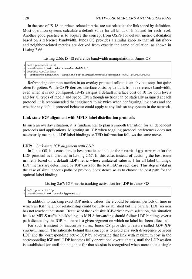
128 NETWORK MERGERS AND MIGRATIONS
In the case of IS–IS, interface-related metrics are not related to the link speed by definition.Most operation systems calculate a default value for all kinds of links and for each level.Another good practice is to acquire the concept from OSPF for default metric calculationbased on a reference bandwidth. Junos OS provides a similar knob so that all interface-and neighbor-related metrics are derived from exactly the same calculation, as shown inListing 2.66.
Listing 2.66: IS–IS reference bandwidth manipulation in Junos OS
1 [edit protocols isis]2 user@Livorno# set reference-bandwidth ?3 Possible completions:4 <reference-bandwidth> Bandwidth for calculating metric defaults (9600..1000000000000)
Referencing common metrics in an overlay protocol rollout is an obvious step, but quiteoften forgotten. While OSPF derives interface costs, by default, from a reference bandwidth,even when it is not configured, IS–IS assigns a default interface cost of 10 for both levelsand for all types of media and speed. Even though metrics can be statically assigned at eachprotocol, it is recommended that engineers think twice when configuring link costs and seewhether any default protocol behavior could apply at any link on any system in the network.
Link-state IGP alignment with MPLS label distribution protocols
In such an overlay situation, it is fundamental to plan a smooth transition for all dependentprotocols and applications. Migrating an IGP when toggling protocol preferences does notnecessarily mean that LDP label bindings or TED information follows the same move.
LDP: Link-state IGP alignment with LDPIn Junos OS, it is considered a best practice to include the track-igp-metric for the
LDP protocol as illustrated in Listing 2.67. In this case, instead of deciding the best routein inet.3 based on a default LDP metric whose unilateral value is 1 for all label bindings,LDP metrics are determined by IGP costs for the best FEC in each case. This step is vital inthe case of simultaneous paths or protocol coexistence so as to choose the best path for theoptimal label binding.
Listing 2.67: IGP metric tracking activation for LDP in Junos OS
1 [edit protocols ldp]2 user@Livorno# set track-igp-metric
In addition to tracking exact IGP metric values, there could be interim periods of time inwhich an IGP neighbor relationship could be fully established but the parallel LDP sessionhas not reached that status. Because of the exclusive IGP-driven route selection, this situationleads to MPLS traffic blackholing, as MPLS forwarding should follow LDP bindings over apath dictated by the IGP, but there is a given segment on which no label has been allocated.
For such transient or inaccurate states, Junos OS provides a feature called LDP-IGPsynchronization. The rationale behind this concept is to avoid any such divergence betweenLDP and the corresponding active IGP by advertising that link with maximum cost in thecorresponding IGP until LDP becomes fully operational over it, that is, until the LDP sessionis established (or until the neighbor for that session is recognized when more than a single

LINK-STATE IGP MIGRATIONS 129
link exists for an LDP session peer) and the label database is exchanged. During this period oftime, the link has the maximum IGP metric value, which has the clear drawback of affectingtraffic which is not MPLS-switched, although this interface with maximum metric is stillpresent and eligible for CSPF computations.
Note that configuration of this feature in Junos OS for both OSPFv2 and IS–IS is notglobal but per interface and can therefore be further tuned with fine-grained control on a per-link basis. Doing this is as simple as attaching the ldp-synchronization knob to therespective interface stanza inside each protocol, as shown in Listing 2.68.
Listing 2.68: LDP–IGP synchronization activation on a given interface in OSPFv2 and IS–ISin Junos OS
1 [edit protocols ospf]2 user@Livorno# set area 0 interface so-0/0/0.0 ldp-synchronization3 [edit protocols isis]4 user@Livorno# set interface so-0/0/0.0 ldp-synchronization
Considering our lab topology and assuming parallel deployment of flat OSPFv2 and IS–IS Level 2 with default preferences, as shown in Figure 2.14, misconfiguration of LDP–IGPsynchronization can have an even more dramatic impact that results from misalignment incost assignment to different links. Listing 2.69 depicts an example situation in this setup inwhich only OSPFv2 is configured with LDP–IGP synchronization and the LDP session overa certain interface is torn down, here with manual intervention (consider flaps or human errorsin a live network).
Male
Bilbao
Havana
Nantes
Skopie
Livorno Barcelona
Honolulu
192.168.1.4
192.168.1.20
192.168.1.8
192.168.1.1
192.168.1.2
192.168.1.6 192.168.1.7
192.168.1.21
IS−IS Level 2 Backbone
OSPF Area 0 Backbone
Figure 2.14: Network topology with flat OSPFv2 Area 0 and uniform IS–IS Level 2.
Listing 2.69: LDP–IGP synchronization misalignment effect in Livorno towards Bilbao
1 user@Livorno> show route 192.168.1.82
3 inet.0: 9830 destinations, 9859 routes (9829 active, 0 holddown, 1 hidden)4 + = Active Route, - = Last Active, * = Both

130 NETWORK MERGERS AND MIGRATIONS
5
6 192.168.1.8/32 *[OSPF/10] 00:07:06, metric 9037 > via so-0/0/0.08 [IS-IS/18] 00:07:05, metric 9039 > to 172.16.1.33 via so-0/0/0.0
10
11 inet.3: 10 destinations, 11 routes (10 active, 0 holddown, 0 hidden)12 + = Active Route, - = Last Active, * = Both13
14 192.168.1.8/32 *[LDP/9] 00:07:06, metric 90315 > via so-0/0/0.0, Push 29987216
17 user@Livorno> configure18 Entering configuration mode19
20 [edit]21 user@Livorno# set protocols ldp interface so-0/0/0.0 disable22 [edit]23 user@Livorno# set protocols ospf area 0 interface so-0/0/0.0 ldp-synchronization24 [edit]25 user@Livorno# commit and-quit26 commit complete27 Exiting configuration mode28
29 user@Livorno> show route 192.168.1.830
31 inet.0: 9830 destinations, 9859 routes (9829 active, 0 holddown, 1 hidden)32 + = Active Route, - = Last Active, * = Both33
34 192.168.1.8/32 *[OSPF/10] 00:00:06, metric 154635 > via so-0/0/1.036 [IS-IS/18] 00:08:38, metric 90337 > to 172.16.1.33 via so-0/0/0.038
39 inet.3: 10 destinations, 11 routes (10 active, 0 holddown, 0 hidden)40 + = Active Route, - = Last Active, * = Both41
42 192.168.1.8/32 *[LDP/9] 00:00:06, metric 154643 > via so-0/0/1.0, Push 303280
Whenever that interface in router Livorno is disabled in LDP and LDP–IGP synchroniza-tion is active with OSPF (Line 22), router Livorno selects another path with a higher metricbut keeps the OSPF route active, being a preferred protocol.
In that situation, if router Havana, which is on the other side of the LDP-synced link,had already moved to IS–IS Level 2 as the preferred protocol, while router Livorno keepsselecting OSPF as the preferred protocol, a routing loop could have been formed because ofindirect path selection divergence between both IGPs. In fact, this is the very same effect ofnot assigning the same or proportional link costs at coexisting IGPs in the same topology.
The bottom line in this situation is that errors in the different cost parameters arenot obvious in such transition scenarios and it is therefore recommended that LDP–IGPsynchronization configuration be aligned on a per-link basis when link-state IGPs areoperating as ships-in-the-night.
RSVP: Link-state IGP alignment with RSVP-TETE metrics can be further tuned and even become independent of the simple IGP link cost.Both OSPF and IS–IS TE resources include fields to attach specific TE metrics to each link.Listing 2.70 shows the configuration changes needed to specify a different metric on a givenlink in OSPFv2 and IS–IS (on a per level basis).

LINK-STATE IGP MIGRATIONS 131
Listing 2.70: TE metric configuration in OSPFv2 and IS–IS
1 [edit]2 user@Livorno# set protocols ospf area 0 interface so-0/0/0.0 te-metric 10003 [edit]4 user@Livorno# set protocols isis interface so-0/0/0.0 level 1 te-metric 10005 [edit]6 user@Livorno# set protocols isis interface so-0/0/0.0 level 2 te-metric 1000
Also, the transition of IGP route preference does not necessarily mean that informationinjection in the TED for RSVP calculations needs to be aligned with the IGP preferencechange. Junos OS can further fine-tune this potential divergence between IGP route prefer-ence and TED information with a concept called TED protocol credibility.
By default, Junos OS always prefers IS–IS information in the TED in preference toinformation from other IGPs, even if these IGPs have better route preference. For instance,this situation may occur when IS–IS and OSPF coexist in the same setup, as OSPF is assignedwith lower preference values by default, as shown in Table 2.7.
Junos OS has added a specific knob for OSPF version 2 and IS–IS, as seen in Listings 2.71and 2.72, to tweak this behavior so that TED information is made dependent on the currentIGP preference, thus allowing the IGP preference to automatically determine TED credibility.
Listing 2.71: Activation of TED protocol credibility for OSPF version 2 in Junos OS
1 [edit protocols ospf]2 user@Livorno# set traffic-engineering credibility-protocol-preference
Listing 2.72: Activation of TED protocol credibility for IS–IS in Junos OS
1 [edit protocols isis]2 user@Livorno# set traffic-engineering credibility-protocol-preference
In fact, when the credibility-protocol-preference is active, the followingcalculation is implemented to determine the value:
[TED credibility] = 512 − [IGP preference].In this case, the IGP with the highest credibility is chosen. The credibility is for the whole
TED database and not per link or per node, so this feature has global scope. Note as well thatwhile lower standard IGP preference values indicate stronger predilection, TED credibilityfollows an ascending scheme and more credible protocols for TED are chosen based onhigher values.
In Junos OS, protocols are sorted according to protocol credibility when injectinginformation in the TED. When a certain IGP adds node and link information to the TED, thesedetails are inserted into a list based on the TED protocol preference, starting with the mostpreferred protocol. The implementation of this feature does not preclude full repopulation ofthe TED but simply reordering the protocol list, because the information is already presentwith the protocol traffic-engineering information extensions.
However, when a given user changes such protocol preference, the old TED informationis destroyed and TED is populated with the newly available information for the instances thathave traffic-engineering.
Another side effect is that any changes in the standard IGP preference value alsoinfluence TED credibility with this knob active and automatically feed the TED with thenew information. This means that repopulation not only takes place when activating or
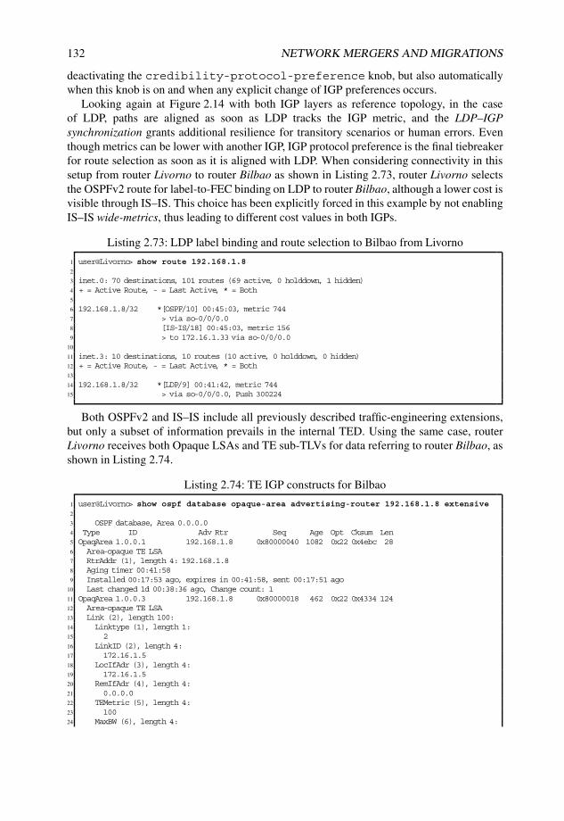
132 NETWORK MERGERS AND MIGRATIONS
deactivating the credibility-protocol-preference knob, but also automaticallywhen this knob is on and when any explicit change of IGP preferences occurs.
Looking again at Figure 2.14 with both IGP layers as reference topology, in the caseof LDP, paths are aligned as soon as LDP tracks the IGP metric, and the LDP–IGPsynchronization grants additional resilience for transitory scenarios or human errors. Eventhough metrics can be lower with another IGP, IGP protocol preference is the final tiebreakerfor route selection as soon as it is aligned with LDP. When considering connectivity in thissetup from router Livorno to router Bilbao as shown in Listing 2.73, router Livorno selectsthe OSPFv2 route for label-to-FEC binding on LDP to router Bilbao, although a lower cost isvisible through IS–IS. This choice has been explicitly forced in this example by not enablingIS–IS wide-metrics, thus leading to different cost values in both IGPs.
Listing 2.73: LDP label binding and route selection to Bilbao from Livorno
1 user@Livorno> show route 192.168.1.82
3 inet.0: 70 destinations, 101 routes (69 active, 0 holddown, 1 hidden)4 + = Active Route, - = Last Active, * = Both5
6 192.168.1.8/32 *[OSPF/10] 00:45:03, metric 7447 > via so-0/0/0.08 [IS-IS/18] 00:45:03, metric 1569 > to 172.16.1.33 via so-0/0/0.0
10
11 inet.3: 10 destinations, 10 routes (10 active, 0 holddown, 0 hidden)12 + = Active Route, - = Last Active, * = Both13
14 192.168.1.8/32 *[LDP/9] 00:41:42, metric 74415 > via so-0/0/0.0, Push 300224
Both OSPFv2 and IS–IS include all previously described traffic-engineering extensions,but only a subset of information prevails in the internal TED. Using the same case, routerLivorno receives both Opaque LSAs and TE sub-TLVs for data referring to router Bilbao, asshown in Listing 2.74.
Listing 2.74: TE IGP constructs for Bilbao
1 user@Livorno> show ospf database opaque-area advertising-router 192.168.1.8 extensive2
3 OSPF database, Area 0.0.0.04 Type ID Adv Rtr Seq Age Opt Cksum Len5 OpaqArea 1.0.0.1 192.168.1.8 0x80000040 1082 0x22 0x4ebc 286 Area-opaque TE LSA7 RtrAddr (1), length 4: 192.168.1.88 Aging timer 00:41:589 Installed 00:17:53 ago, expires in 00:41:58, sent 00:17:51 ago
10 Last changed 1d 00:38:36 ago, Change count: 111 OpaqArea 1.0.0.3 192.168.1.8 0x80000018 462 0x22 0x4334 12412 Area-opaque TE LSA13 Link (2), length 100:14 Linktype (1), length 1:15 216 LinkID (2), length 4:17 172.16.1.518 LocIfAdr (3), length 4:19 172.16.1.520 RemIfAdr (4), length 4:21 0.0.0.022 TEMetric (5), length 4:23 10024 MaxBW (6), length 4:

LINK-STATE IGP MIGRATIONS 133
25 1000Mbps26 MaxRsvBW (7), length 4:27 1000Mbps28 UnRsvBW (8), length 32:29 <...>30 Color (9), length 4:31 032 Aging timer 00:52:1833 Installed 00:07:33 ago, expires in 00:52:18, sent 00:07:31 ago34 Last changed 15:26:21 ago, Change count: 135
36 user@Livorno> show isis database Bilbao-re0.00-00 extensive37 IS-IS level 1 link-state database:38
39 IS-IS level 2 link-state database:40
41 Bilbao-re0.00-00 Sequence: 0xe95, Checksum: 0x3ce1, Lifetime: 598 secs42 IS neighbor: Torino.00 Metric: 6343 IS neighbor: male.00 Metric: 6344 IP prefix: 172.16.1.4/30 Metric: 63 Internal Up45 IP prefix: 172.16.1.76/30 Metric: 63 Internal Up46 IP prefix: 192.168.1.8/32 Metric: 0 Internal Up47 <...>48 TLVs:49 Area address: 49.0004 (3)50 Speaks: IP51 Speaks: IPV652 IP router id: 192.168.1.853 IP address: 192.168.1.854 Hostname: Bilbao-re055 IS neighbor: Nantes.02, Internal, Metric: default 6356 IS neighbor: male.00, Internal, Metric: default 6357 IS extended neighbor: Nantes.02, Metric: default 6358 IP address: 172.16.1.559 Local interface index: 77, Remote interface index: 060 Current reservable bandwidth:61 <...>62 Maximum reservable bandwidth: 1000Mbps63 Maximum bandwidth: 1000Mbps64 Administrative groups: 0 <none>65 IS extended neighbor: male.00, Metric: default 6366 IP address: 172.16.1.7867 Neighbor’s IP address: 172.16.1.7768 Local interface index: 70, Remote interface index: 9569 IP prefix: 172.16.1.4/30, Internal, Metric: default 63, Up70 IP prefix: 192.168.1.8/32, Internal, Metric: default 0, Up71 IP prefix: 172.16.1.76/30, Internal, Metric: default 63, Up72 IP extended prefix: 172.16.1.4/30 metric 63 up73 IP extended prefix: 192.168.1.8/32 metric 0 up74 IP extended prefix: 172.16.1.76/30 metric 63 up75 No queued transmissions
However, each protocol has a given strict credibility to inject such information in the routerTED. Listing 2.75 shows the TED status in our example.
Listing 2.75: TE protocol credibility and database entry for router Bilbao in router Livorno
1 user@Livorno> show ted protocol2 Protocol name Credibility Self node3 IS-IS(2) 2 Livorno.00(192.168.1.6)4 IS-IS(1) 15 OSPF(0) 0 Livorno.00(192.168.1.6)6
7 user@Livorno> show ted database 192.168.1.8 extensive8 TED database: 16 ISIS nodes 16 INET nodes9 NodeID: Bilbao-re0.00(192.168.1.8)
10 Type: Rtr, Age: 184 secs, LinkIn: 3, LinkOut: 211 Protocol: IS-IS(2) # Higher credibility for IS-IS injected information

134 NETWORK MERGERS AND MIGRATIONS
12 To: Nantes.02, Local: 172.16.1.5, Remote: 0.0.0.013 Local interface index: 71, Remote interface index: 014 Color: 0 <none>15 Metric: 6316 Static BW: 1000Mbps17 Reservable BW: 1000Mbps18 Available BW [priority] bps:19 [0] 1000Mbps [1] 1000Mbps [2] 1000Mbps [3] 1000Mbps20 [4] 1000Mbps [5] 1000Mbps [6] 1000Mbps [7] 1000Mbps21 Interface Switching Capability Descriptor(1):22 Switching type: Packet23 Encoding type: Packet24 Maximum LSP BW [priority] bps:25 [0] 1000Mbps [1] 1000Mbps [2] 1000Mbps [3] 1000Mbps26 [4] 1000Mbps [5] 1000Mbps [6] 1000Mbps [7] 1000Mbps27 Protocol: OSPF(0.0.0.0) # Lower credibility for OSPF injected information28 To: 172.16.1.5-1, Local: 172.16.1.5, Remote: 0.0.0.029 Local interface index: 0, Remote interface index: 030 Color: 0 <none>31 Metric: 10032 Static BW: 1000Mbps33 Reservable BW: 1000Mbps34 Available BW [priority] bps:35 [0] 1000Mbps [1] 1000Mbps [2] 1000Mbps [3] 1000Mbps36 [4] 1000Mbps [5] 1000Mbps [6] 1000Mbps [7] 1000Mbps37 Interface Switching Capability Descriptor(1):38 Switching type: Packet39 Encoding type: Packet40 Maximum LSP BW [priority] bps:41 [0] 1000Mbps [1] 1000Mbps [2] 1000Mbps [3] 1000Mbps42 [4] 1000Mbps [5] 1000Mbps [6] 1000Mbps [7] 1000Mbps
In this situation, if divergences in the IGP topologies are created by deactivating IS–IS onthe best path interface to router Bilbao and a simple RSVP-based LSP is defined from routerLivorno, differences in the path computation become explicit, as shown in Listing 2.76.
Listing 2.76: IGP and TE divergences towards router Bilbao in router Livorno
1 [edit]2 user@Livorno# set protocols mpls label-switched-path Livorno-to-Bilbao to 192.168.1.83 [edit]4 user@Livorno# set protocols isis interface so-0/0/0.0 disable5 [edit]6 user@Livorno# commit and-quit7 commit complete8 Exiting configuration mode9
10 user@Livorno> show route 192.168.1.811
12 inet.0: 72 destinations, 105 routes (71 active, 0 holddown, 1 hidden)13 + = Active Route, - = Last Active, * = Both14
15 192.168.1.8/32 *[OSPF/10] 00:02:17, metric 74416 > via so-0/0/0.017 [IS-IS/18] 00:01:48, metric 18918 > to 172.16.1.37 via so-0/0/1.019
20 inet.3: 10 destinations, 12 routes (10 active, 0 holddown, 0 hidden)21 + = Active Route, - = Last Active, * = Both22
23 192.168.1.8/32 *[RSVP/7] 00:01:57, metric 74424 > via so-0/0/1.0, label-switched-path Livorno-to-Bilbao25 [LDP/9] 00:02:05, metric 74426 > via so-0/0/0.0, Push 30022427
28 user@Livorno> show ted protocol29 Protocol name Credibility Self node

LINK-STATE IGP MIGRATIONS 135
30 IS-IS(2) 2 Livorno.00(192.168.1.6)31 IS-IS(1) 132 OSPF(0) 0 Livorno.00(192.168.1.6)
The following items are worth noting in Listing 2.76:
• Even though OSPF internal is preferred, RSVP-TE follows the IS–IS path because itis the protocol with the highest TED credibility.
• Despite selecting the IS–IS path, the RSVP-TE route in inet.3 includes the OSPF routemetric because such metric is not strictly part of the TE extensions.
• Junos OS default values without considering TED credibility knobs derive from theselection of different IGPs, depending on the application.
The status shown above could easily be a transient or even a permanent situation dur-ing a migration period. The traffic-engineering credibility-protocol-preference configuration resource allows the IGP preference to align with TED credi-bility.
If the TED protocol credibility is adapted, OSPFv2 then becomes the preferred protocolwith regards to MPLS path selection, as shown in Listing 2.77. By clearing the LSP foroptimization, recomputation towards the new route is forced.
Listing 2.77: TED protocol credibility adaption in Bilbao
1 user@Livorno> configure2 Entering configuration mode3
4 [edit]5 user@Livorno# set protocols ospf traffic-engineering credibility-protocol-preference6 [edit]7 user@Livorno# set protocols isis traffic-engineering credibility-protocol-preference8
9 user@Livorno> clear mpls lsp optimize10
11 user@Livorno> show route 192.168.1.812
13 inet.0: 72 destinations, 105 routes (71 active, 0 holddown, 1 hidden)14 + = Active Route, - = Last Active, * = Both15
16 192.168.1.8/32 *[OSPF/10] 00:16:51, metric 74417 > via so-0/0/0.018 [IS-IS/18] 00:16:22, metric 18919 > to 172.16.1.37 via so-0/0/1.020
21 inet.3: 10 destinations, 12 routes (10 active, 0 holddown, 0 hidden)22 + = Active Route, - = Last Active, * = Both23
24 192.168.1.8/32 *[RSVP/7] 00:01:05, metric 74425 > via so-0/0/0.0, label-switched-path Livorno-to-Bilbao26 [LDP/9] 00:16:39, metric 74427 > via so-0/0/0.0, Push 30022428
29 user@Livorno> show ted protocol30 Protocol name Credibility Self node31 OSPF(0) 502 Livorno.00(192.168.1.6)32 IS-IS(1) 49733 IS-IS(2) 494 Livorno.00(192.168.1.6)34
35 user@Livorno> show ted database 192.168.1.8 extensive36 TED database: 16 ISIS nodes 16 INET nodes37 NodeID: Bilbao-re0.00(192.168.1.8)

136 NETWORK MERGERS AND MIGRATIONS
38 Type: Rtr, Age: 53 secs, LinkIn: 3, LinkOut: 239 Protocol: OSPF(0.0.0.0) # Higher credibility for OSPF injected information40 To: 172.16.1.5-1, Local: 172.16.1.5, Remote: 0.0.0.041 Local interface index: 0, Remote interface index: 042 Color: 0 <none>43 Metric: 10044 Static BW: 1000Mbps45 Reservable BW: 1000Mbps46 <...>47 Protocol: IS-IS(2) # Lower credibility for IS-IS injected information48 To: Nantes.02, Local: 172.16.1.5, Remote: 0.0.0.049 Local interface index: 71, Remote interface index: 050 Color: 0 <none>51 Metric: 6352 Static BW: 1000Mbps53 Reservable BW: 1000Mbps54 <...>
In this setup and with this configuration, both IP and MPLS TE path selection are alignedas dictated by the most preferred and TED-credible IGP. In this context, it is considered abest practice to encompass any IGP preference modification with TED protocol credibilityadaptions for route selection to be mirrored in the TED using traffic-engineeringcredibility-protocol-preference knobs in the respective IGPs.
In this state, when tweaking the IS–IS Level 2 internal preference on router Livorno tobe preferred against OSPF internal routes, this change is immediately followed by preferringthat link-state IGP for TED computations as well. Listing 2.78 illustrates the results for thischange with an MPLS path reoptimization.
Listing 2.78: IS–IS Level 2 internal preference modified in Livorno
1 [edit]2 user@Livorno# set protocols isis level 2 preference 83 [edit]4 user@Livorno# commit and-quit5 commit complete6 Exiting configuration mode7
8 user@Livorno> clear mpls lsp optimize9 user@Livorno> show route 192.168.1.8
10
11 inet.0: 72 destinations, 105 routes (71 active, 0 holddown, 1 hidden)12 + = Active Route, - = Last Active, * = Both13
14 192.168.1.8/32 *[IS-IS/8] 00:00:31, metric 18915 > to 172.16.1.37 via so-0/0/1.016 [OSPF/10] 00:23:11, metric 74417 > via so-0/0/0.018
19 inet.3: 10 destinations, 12 routes (10 active, 0 holddown, 0 hidden)20 + = Active Route, - = Last Active, * = Both21
22 192.168.1.8/32 *[RSVP/7] 00:00:05, metric 18923 > via so-0/0/1.0, label-switched-path Livorno-to-Bilbao24 [LDP/9] 00:00:31, metric 18925 > via so-0/0/1.0, Push 30100826
27 user@Livorno> show ted protocol28 Protocol name Credibility Self node29 IS-IS(2) 504 Livorno.00(192.168.1.6)30 OSPF(0) 502 Livorno.00(192.168.1.6)31 IS-IS(1) 49732
33 user@Livorno> show ted database 192.168.1.8 extensive34 TED database: 16 ISIS nodes 16 INET nodes

LINK-STATE IGP MIGRATIONS 137
35 NodeID: Bilbao-re0.00(192.168.1.8)36 Type: Rtr, Age: 403 secs, LinkIn: 3, LinkOut: 237 Protocol: IS-IS(2) # Higher credibility for IS-IS injected information38 To: Nantes.02, Local: 172.16.1.5, Remote: 0.0.0.039 Local interface index: 71, Remote interface index: 040 Color: 0 <none>41 Metric: 6342 Static BW: 1000Mbps43 Reservable BW: 1000Mbps44 <...>45 Protocol: OSPF(0.0.0.0) # Lower credibility for OSPF injected information46 To: 172.16.1.5-1, Local: 172.16.1.5, Remote: 0.0.0.047 Local interface index: 0, Remote interface index: 048 Color: 0 <none>49 Metric: 10050 Static BW: 1000Mbps51 Reservable BW: 1000Mbps52 <...>
It is worth noting the following from Listing 2.78:
• LDP follows the path dictated by the IS–IS internal route because of the lowerpreference.
• RSVP-TE follows the path dictated by the IS–IS internal route because it is the mostcredible protocol for the TED.
• Alignment between both label distribution protocols is automatically achieved whenusing traffic-engineering credibility-protocol-preference.
Link-state IGP adjacency transition for MPLS label distribution protocols
When deploying parallel IGP layers, once topologies have converged to select the same bestpaths, achieving a smooth transition for applications when moving from one IGP to anotherso as to pick up the active route is a vital factor for a close-to-hitless migration strategy.
Among those applications, MPLS labels and related protocols rank nowadays as themost expensive customers relying on IGP convergence and stability, especially as more andmore MPLS-based services appear in networks. Although IGPs ultimately dictate paths anddetermine label selection at each ingress and transit node, even when IGPs are selectingthe same next hop and determining the same label, some implications exist in MPLS labeldistribution protocols when preferring a new IGP route against an older one.
RSVP: By default, Junos OS tracks the IS–IS and OSPF adjacency state in RSVP.Traffic-engineering link and node information are deleted by default when a link-state IGP
adjacency is torn down, bringing down MPLS LSPs traversing through it. Also, as Junos OSnotifies RSVP modules of the IGP adjacency drop, the RSVP neighbor is brought down aswell. Even though IGP preferences and TED credibility can be tweaked without impactingRSVP neighbor relationships, this default behavior poses a challenge to maintaining theMPLS RSVP state and LSP forwarding at a later stage in a migration period, for instance,when removing adjacencies from unpreferred IGPs in a cleanup stage.
The no-neighbor-down-notification knob for OSPFv2 interfaces and theno-adjacency-down-notification knob for IS–IS interfaces provide a mechanismto ignore the IGP notification to RSVP and therefore ensure a completely hitless migration

138 NETWORK MERGERS AND MIGRATIONS
with regards to RSVP. Under normal circumstances, notifying RSVP upon IGP adjacencyloss is considered to be an improvement with regards to convergence.
After attaching the knob to the respective interface, Junos OS requires the interface firstto be deactivated at the IGP stanza. Once the adjacency has disappeared, that interface canbe safely removed from the corresponding stanza. This transition in two steps is needed sothat Junos OS first couples interface deactivation with the lack of an IGP adjacency lossnotification to RSVP. This unused configuration snippet can be deleted at a later stage.
This feature also needs symmetric activation on all participating systems in the attachedmedia. This alignment is needed so that no directly connected systems tear down RSVPneighbors and transit LSPs when the IGP adjacency timer expires. If the feature is notconfigured on all ends of the interface, and not only at ingress or egress LSP endpointsbut also on the LSP transit systems, whichever system detects either an OSPF neighborrelationship or an IS–IS adjacency expiration when the interface first gets deactivated,triggers the LSP teardown in its direction.
For all these reasons, this feature is tremendously helpful in the later stages of a migrationfor a proper and hitless cleanup. However, it needs to be either globally deployed orrolled out carefully in interface groupings of attached routers. Listing 2.79 summarizesthe configuration steps needed for both OSPFv2 and IS–IS with the previous scenario andincludes steps in router Skopie, which is the router on the other end of the interface.
Listing 2.79: Per-interface configuration for OSPFv2 no-neighbor-down-notification and IS–IS no-adjacency-down-notification on router Livorno and router Skopie
1 user@Livorno> show route 192.168.1.8 detail2
3 inet.0: 78 destinations, 118 routes (77 active, 0 holddown, 1 hidden)4 192.168.1.8/32 (2 entries, 1 announced)5 *IS-IS Preference: 86 Level: 27 Next hop type: Router, Next hop index: 2621438 Next-hop reference count: 559 Next hop: 172.16.1.33 via so-0/0/0.0, selected
10 State: <Active Int>11 Local AS: 6453012 Age: 1d 1:18:17 Metric: 90313 Task: IS-IS14 Announcement bits (3): 0-KRT 4-LDP 7-Resolve tree 415 AS path: I16 OSPF Preference: 1017 Next hop type: Router, Next hop index: 26214718 Next-hop reference count: 719 Next hop: via so-0/0/0.0, selected20 State: <Int>21 Inactive reason: Route Preference22 Local AS: 6453023 Age: 1d 0:33:04 Metric: 90324 Area: 0.0.0.025 Task: OSPF26 AS path: I27
28 inet.3: 9 destinations, 12 routes (9 active, 0 holddown, 0 hidden)29
30 192.168.1.8/32 (2 entries, 1 announced)31 State: <FlashAll>32 *RSVP Preference: 733 Next hop type: Router34 Next-hop reference count: 535 Next hop: via so-0/0/0.0 weight 0x1, selected36 Label-switched-path Livorno-to-Bilbao

LINK-STATE IGP MIGRATIONS 139
37 Label operation: Push 30054438 State: <Active Int>39 Local AS: 6453040 Age: 1d 0:34:28 Metric: 90341 Task: RSVP42 Announcement bits (2): 2-Resolve tree 1 4-Resolve tree 443 AS path: I44 LDP Preference: 945 Next hop type: Router46 Next-hop reference count: 147 Next hop: via so-0/0/0.0, selected48 Label operation: Push 29987249 State: <Int>50 Inactive reason: Route Preference51 Local AS: 6453052 Age: 1d 1:18:17 Metric: 90353 Task: LDP54 AS path: I55 [edit protocols ospf area 0]56 user@Livorno# set interface so-0/0/0.0 no-neighbor-down-notification57 [edit]58 user@Livorno# set protocols isis interface so-0/0/0.0 no-adjacency-down-notification59 [edit[60 user@Livorno# commit and-quit61 commit complete62 Exiting configuration mode63
64 [edit]65 user@Skopie# set protocols isis interface so-1/0/0.0 no-adjacency-down-notification66 [edit protocols ospf area 0]67 user@Skopie# set interface so-1/0/0.0 no-neighbor-down-notification68 [edit[69 user@Skopie# commit and-quit70 commit complete71 Exiting configuration mode
Note from Listing 2.79 that it is not strictly necessary to activate the feature at IS–IS,because the final intention is to clean up OSPF configuration and the IS–IS Level 2 internalroute is currently preferred. Nevertheless, the activation for IS–IS has been included forillustration purposes. Listing 2.80 summarizes the final steps needed to tear down the OSPFadjacency over the interface in a graceful manner for RSVP.
Listing 2.80: RSVP impact with OSPFv2 no-neighbor-down-notification on Livorno andSkopie
1 [edit]2 user@Livorno# deactivate protocols ospf area 0 interface so-0/0/0.03 [edit]4 user@Livorno# commit and-quit5 Feb 22 21:36:22.057 Livorno rpd[24428]: RPD_OSPF_NBRDOWN: OSPF neighbor 172.16.1.33 (realm ospf-v2
so-0/0/0.0 area 0.0.0.0) state changed from Full to Down due to KillNbr (event reason:interface went down)
6 commit complete7 Exiting configuration mode8
9 user@Livorno> show route 192.168.1.8 detail10
11 inet.0: 78 destinations, 118 routes (77 active, 0 holddown, 1 hidden)12 192.168.1.8/32 (2 entries, 1 announced)13 *IS-IS Preference: 814 Level: 215 Next hop type: Router, Next hop index: 26214316 Next-hop reference count: 5517 Next hop: 172.16.1.33 via so-0/0/0.0, selected18 State: <Active Int>19 Local AS: 64530

140 NETWORK MERGERS AND MIGRATIONS
20 Age: 1d 1:19:36 Metric: 90321 Task: IS-IS22 Announcement bits (3): 0-KRT 4-LDP 7-Resolve tree 423 AS path: I24 OSPF Preference: 1025 Next hop type: Router, Next hop index: 70126 Next-hop reference count: 3627 Next hop: via so-0/0/1.0, selected28 State: <Int>29 Inactive reason: Route Preference30 Local AS: 6453031 Age: 46 Metric: 91332 Area: 0.0.0.033 Task: OSPF34 AS path: I35
36 inet.3: 9 destinations, 12 routes (9 active, 0 holddown, 0 hidden)37
38 192.168.1.8/32 (2 entries, 1 announced)39 State: <FlashAll>40 *RSVP Preference: 741 Next hop type: Router42 Next-hop reference count: 543 Next hop: via so-0/0/0.0 weight 0x1, selected44 Label-switched-path Livorno-to-Bilbao45 Label operation: Push 30054446 State: <Active Int>47 Local AS: 6453048 Age: 1d 0:35:47 Metric: 90349 Task: RSVP50 Announcement bits (2): 2-Resolve tree 1 4-Resolve tree 451 AS path: I52 LDP Preference: 953 Next hop type: Router54 Next-hop reference count: 155 Next hop: via so-0/0/0.0, selected56 Label operation: Push 29987257 State: <Int>58 Inactive reason: Route Preference59 Local AS: 6453060 Age: 1d 1:19:36 Metric: 90361 Task: LDP62 AS path: I63
64 *** messages ***65 Feb 22 21:36:56 Skopie rpd[4502]: RPD_OSPF_NBRDOWN: OSPF neighbor 172.16.1.34 (realm ospf-v2 so
-1/0/0.0 area 0.0.0.0) state changed from Full to Down due to InActiveTimer (event reason:neighbor was inactive and declared dead)
Listing 2.80 shows that OSPF neighbors have been gracefully decoupled. Note that theOSPF neighbor relationship has expired on router Skopie after the standard dead interval(40 seconds) without explicit notification in IS–IS or RSVP.
At that point, interfaces can safely be removed from the OSPF area stanza without furtherimpact. Likewise, the process with IS–IS is completely analogous, requiring first featureactivation and later interface deactivation. Once the adjacency expires, the configuration canbe safely cleaned up and standardized.
Link-state IGP migration through authentication
All link-state routing protocols include authentication extensions in different flavors to pro-vide additional confidentiality and robustness for adjacency establishment and informationdistribution.

LINK-STATE IGP MIGRATIONS 141
Although deploying this security paradigm in existing IGP domains is a considerablemigration exercise per se, because these parameters can delimit the scope of a given domain,authentication becomes a powerful tool to contain and differentiate link-state IGP domainsand transition adjacencies from one domain to another.
This consideration is particularly interesting in cases where networks to be merged orsplit share the same link-state IGP (even same OSPF area or IS–IS levels), because properlycrafted authentication settings can provide adequate containment for each domain whiletransitioning devices.
OSPFv2: [RFC2328] already included an authentication specification in its Appendix D,discussing the possibility even of using a different authentication procedure for each IPsubnet. Each OSPFv2 packet header also includes an authentication type and 64-bit valuefield, which ensures consistency on all types of OSPFv2 exchange.
Junos OS includes support for all [RFC2328] authentication types inside each area on aper-interface basis with an additional feature that becomes interesting for migration purposes:soft authentication-key transition in a synchronized fashion. Note that this does not apply tosimple-password authentication, but applies to MD5 authentication. Listing 2.81 illustrates asample timed activation of MD5 keys and Listing 2.82 shows that this modification is entirelygraceful on both sides: there is no adjacency drop or expiration, and routers suddenly start toinclude newer authentication details in all OSPFv2 packet headers for that adjacency.
Listing 2.81: Configuration of OSPFv2 adjacency MD5 key transition between Livorno andSkopie
1 [edit protocols ospf area 0.0.0.0 interface so-0/0/0.0]2 user@Livorno# set authentication md5 1 key europe start-time 2009-02-27.12:003 [edit protocols ospf area 0.0.0.0 interface so-0/0/0.0]4 user@Skopie# set authentication md5 1 key europe start-time 2009-02-27.12:00
Listing 2.82: Soft synchronized OSPFv2 adjacency MD5 key transition between Livorno andSkopie
1 # OSPF Database prior to changes2
3 user@Skopie> show ospf database | match 192.168.1.64 Router 192.168.1.6 192.168.1.6 0x80000a93 58 0x22 0xd205 1325 OpaqArea 1.0.0.1 192.168.1.6 0x80000a90 467 0x22 0xc489 286 OpaqArea 1.0.0.3 192.168.1.6 0x80000a90 467 0x22 0x65c9 1247 OpaqArea 1.0.0.4 192.168.1.6 0x80000a90 467 0x22 0xaa3b 1248 OpaqArea 1.0.0.5 192.168.1.6 0x80000a90 467 0x22 0x1c57 1249 OpaqArea 1.0.0.6 192.168.1.6 0x80000a90 467 0x22 0x4f19 124
10
11 # OSPF interface status after activation12
13 user@Livorno> show ospf interface so-0/0/0.0 extensive14 Interface State Area DR ID BDR ID Nbrs15 so-0/0/0.0 PtToPt 0.0.0.0 0.0.0.0 0.0.0.0 116 Type: P2P, Address: 0.0.0.0, Mask: 0.0.0.0, MTU: 4470, Cost: 64317 Adj count: 118 Hello: 10, Dead: 40, ReXmit: 5, Not Stub19 Auth type: MD5, Active key ID: 1, Start time: 2009 Feb 27 12:00:00 CET20 so-0/0/0.0 PtToPt 0.0.0.0 0.0.0.0 0.0.0.0 021 Type: P2P, Address: 172.16.1.34, Mask: 255.255.255.252, MTU: 4470, Cost: 64322 Adj count: 0, , Passive23 Hello: 10, Dead: 40, ReXmit: 5, Not Stub24 Auth type: MD5, Active key ID: 1, Start time: 2009 Feb 27 12:00:00 CET

142 NETWORK MERGERS AND MIGRATIONS
25
26 # OSPF Database after activation, no new Sequence Numbers27
28 user@Skopie> show ospf database | match 192.168.1.629 Router 192.168.1.6 192.168.1.6 0x80000a93 190 0x22 0xd205 13230 OpaqArea 1.0.0.1 192.168.1.6 0x80000a90 599 0x22 0xc489 2831 OpaqArea 1.0.0.3 192.168.1.6 0x80000a90 599 0x22 0x65c9 12432 OpaqArea 1.0.0.4 192.168.1.6 0x80000a90 599 0x22 0xaa3b 12433 OpaqArea 1.0.0.5 192.168.1.6 0x80000a90 599 0x22 0x1c57 12434 OpaqArea 1.0.0.6 192.168.1.6 0x80000a90 599 0x22 0x4f19 124
Based on MD5 authentication settings and transitions, this feature allows smooth expan-sion or constraint of a given domain by progressively activating common or disjoint MD5keys. This feature is even more interesting in a physical broadcast media shared by differentIGP domains, in which participating routers could move from one domain to the other byactivating corresponding MD5 keys (and in this case expiring previous and activating newadjacencies) but without the need to physically split or move them from one logical interfaceto another when transitioning domains.
IS–IS: [ISO10589] advocates the definition of a TLV 10 Authentication to ensure informa-tion integrity and confidentiality at each PDU. Similarly to OSPFv2, two authentication typesare considered: simple Text and HMAC-MD5, although there is no cryptographic sequencenumbering scheme as described in [RFC2328].
The existence of a common Hello PDU type on point-to-point links, as opposed to separateLAN Hello PDUs for Level 1 and Level 2, forces common authentication details to be sharedover both L1 and L2 adjacencies in the common link. In a migration scenario, this factrequires either common authentication settings for that link and the two levels, or ignoringauthentication information for one of them and complying with it for the other.
With Junos OS, a given administrator can control the creation of adjacencies betweenneighbors by configuring authentication keys used in Hello PDUs on a per-interface basis.A separate way to control adjacency creation is by database exchange and LSP floodingby configuring same or different authentication keys on a per-system or per-level basis.Commands included in Listing 2.83 summarize IS–IS authentication setting capabilities.
Listing 2.83: IS–IS generic authentication settings for sending PDUs
1 [edit protocols isis]2 user@Livorno# set level 2 authentication-type md5 # or simple for cleartext3 [edit protocols isis]4 user@Livorno# set level 2 authentication-key Hurricane5 [edit protocols isis interface fe-0/3/3.0]6 user@Livorno# set level 2 hello-authentication-type md5 # or simple for cleartext7 [edit protocols isis interface fe-0/3/3.0]8 user@Livorno# set level 2 hello-authentication-key Hurricane9 [edit protocols isis level 2]
10 user@Livorno# set no-csnp-authentication # Disable Authentication TLV set in CSNPs11 [edit protocols isis level 2]12 user@Livorno# set no-hello-authentication # Disable Authentication TLV set in IIHs13 [edit protocols isis level 2]14 user@Livorno# set no-psnp-authentication # Disable Authentication TLV set in PSNPs
This listing shows that all LSP, CSN, and PSN PDUs can include a different TLV 10Authentication from the Hello PDUs on a certain link and that this can also be disabled inJunos OS on a per-PDU and per-level basis.

LINK-STATE IGP MIGRATIONS 143
Junos OS presents other interesting knobs when processing incoming PDUs with TLV 10Authentication, that easily allow setup of asymmetric authentication.
The loose-authentication-check is a useful resource for progressive authenti-cation deployment and migrations. This knob allows routers to verify MD5 authenticationinformation only if TLV 10 Authentication is present in the PDU; otherwise, processing isdone as normal even though the router is locally configured to attach and detect authenticationsettings. Apart from being able to roll out MD5 authentication incrementally in a network,a system could potentially bridge authenticated and non-authenticated domains withoutneeding to adapt any of either.
Similarly, no-authentication-check goes even further by disabling any kind ofauthentication information parsing in all PDUs. Listing 2.84 depicts those authenticationprocessing exception capabilities.
Listing 2.84: IS–IS global authentication processing exceptions
1 [edit protocols isis]2 user@Havana# set loose-authentication-check3 [edit protocols isis]4 user@Havana# set no-authentication-check
All these features together enable another dimension to use authentication as a vehicle tomerge and separate domains when compared to OSPF, because the distribution of informationcan be authenticated differently at IIHs, CSNPs, PSNPs, and LSPs, or in a global fashionexcluding some of these PDUs. Also, processing such information can be disabled graduallyin different stages without impacting topology reachability.
There is a notable remark in the case of IS–IS. Supporting authentication settings,especially MD5, has been a relatively recent development. Because of the incremental natureof IS–IS information constructs, if authentication-unaware systems receive an authenticatedPDU, they may still deem the PDU as valid, because TLV 10 Authentication may be ignoredor discarded as unknown but its implications are not considered. For that reason, an initialdesign task when using authentication as a migration vehicle is to potentially identify suchcorner cases.
The advantage of using full authentication capabilities is that several domains couldcoexist in the same network without influencing each other’s database. Even without usingany particular mesh groups and because of the flooding nature of IS–IS, a given router in oneof the domains still detects LSP headers, but upon processing authentication information, theTLVs are not further processed.
Application Note: Use of IS–IS authentication options to connectmultiple domains
Consider our well-known topology as depicted in Figure 2.15 and with respective IS–ISdatabase entries as shown in Listing 2.85.
Listing 2.85: Initial IS–IS database status in each domain
1 user@Havana> show isis database2 IS-IS level 1 link-state database:3 0 LSPs4
5 IS-IS level 2 link-state database:6 LSP ID Sequence Checksum Lifetime Attributes

144 NETWORK MERGERS AND MIGRATIONS
7 Nantes.00-00 0x241f 0x71a6 810 L1 L28 Nantes.02-00 0x2d 0xa4f8 1060 L1 L29 Havana.00-00 0x169e 0xb30f 776 L1 L2
10 Havana.02-00 0x4b5 0x9079 776 L1 L211 male-re0.00-00 0x4de 0x1ed5 767 L1 L212 Bilbao-re0.00-00 0x16dd 0x5158 614 L1 L213 6 LSPs14
15 user@Livorno> show isis database16 IS-IS level 1 link-state database:17 0 LSPs18
19 IS-IS level 2 link-state database:20 LSP ID Sequence Checksum Lifetime Attributes21 Lille.00-00 0x290 0x8912 1145 L1 L222 Skopie.00-00 0x1ec1 0x72f5 535 L1 L223 Livorno.00-00 0x5691 0x5bb9 1175 L1 L224 Livorno.02-00 0x2 0x65c4 1179 L1 L225 honolulu-re0.00-00 0x8d9 0x1134 510 L1 L226 honolulu-re0.02-00 0x8ae 0xb667 759 L1 L227 Barcelona-re0.00-00 0x8f3 0x2583 729 L1 L228 Barcelona-re0.02-00 0x8e5 0x7c7f 767 L1 L229 8 LSPs
Male
Bilbao
Havana
Nantes
Skopie
Livorno
Barcelona
Honolulu
IS−IS L2 domain
Key "Typhoon"
IS−IS L2 domain
Key "Hurricane"
Lille
Figure 2.15: Independent IS–IS L2 domains with different authentication MD5 keys.
The loose-authentication-checks are activated in all routers in both domains,as indicated in Listing 2.86 for one system. This step needs to be repeated for allparticipating routers in both domains. Because authentication is still enforced, no routinghas changed so far.
Listing 2.86: Initial loose-authentication-check activation in participating systems at bothdomains
1 [edit protocols isis]2 user@Livorno# set loose-authentication-check

LINK-STATE IGP MIGRATIONS 145
Authentication can be gradually deactivated for systems to be integrated in bothdomains. This process requires both removing any TLV 10 Authentication attachment atPDUs to be sent and ignoring them upon reception.
Considering router Nantes as a system to be shared between both domains, commandsincluded in Listing 2.87 show configuration steps needed for this particular domainstitching.
Listing 2.87: Configuration steps to integrate Nantes in domain “Typhoon”
1 [edit protocols isis]2 user@Nantes# set no-authentication-check3 [edit protocols isis]4 user@Nantes# delete level 2 authentication-key5 [edit protocols isis]6 user@Nantes# delete level 2 authentication-type
After disabling all authentication settings and checks in router Nantes, the systemeffectively merges locally both IS–IS databases, keeping adjacencies up for both of them,as shown in Listing 2.88.
Listing 2.88: Router Nantes integrates locally in both domains
1 # Merged IS-IS Databases in Nantes2 user@Nantes> show isis database3 IS-IS level 1 link-state database:4 0 LSPs5
6 IS-IS level 2 link-state database:7 LSP ID Sequence Checksum Lifetime Attributes8 Nantes.00-00 0x2521 0xebb3 1010 L1 L29 Nantes.02-00 0x116 0x828c 1010 L1 L2
10 Skopie.00-00 0x1fa1 0x43e3 901 L1 L211 Havana.00-00 0x178f 0x3da6 1018 L1 L212 Havana.02-00 0x599 0x5ca6 1018 L1 L213 Lille.00-00 0x4 0xd4d3 951 L1 L214 Livorno.00-00 0x5768 0x10ab 1105 L1 L215 Livorno.02-00 0xdb 0x3d5a 1105 L1 L216 male-re0.00-00 0x5bb 0xd71c 1006 L1 L217 honolulu-re0.00-00 0x9b1 0x70fb 1172 L1 L218 honolulu-re0.02-00 0x985 0x67ce 691 L1 L219 Bilbao-re0.00-00 0x17c0 0xb4d9 1008 L1 L220 Barcelona-re0.00-00 0x9ca 0x9874 668 L1 L221 Barcelona-re0.02-00 0x9bc 0xf10b 917 L1 L222 14 LSPs23
24 # Merged Traffic-Engineering Databases in Nantes25
26 user@Nantes> show ted database27 TED database: 17 ISIS nodes 17 INET nodes28 ID Type Age(s) LnkIn LnkOut Protocol29 Nantes.00(192.168.1.1) Rtr 297 6 7 IS-IS(2)30 To: Skopie.00(192.168.1.2), Local: 172.16.1.1, Remote: 172.16.1.231 Local interface index: 70, Remote interface index: 6732 To: Nantes.02, Local: 172.16.1.6, Remote: 0.0.0.033 Local interface index: 67, Remote interface index: 034 ID Type Age(s) LnkIn LnkOut Protocol35 Nantes.02 Net 297 2 2 IS-IS(2)36 To: Nantes.00(192.168.1.1), Local: 0.0.0.0, Remote: 0.0.0.037 Local interface index: 0, Remote interface index: 038 To: Bilbao-re0.00(192.168.1.8), Local: 0.0.0.0, Remote: 0.0.0.039 Local interface index: 0, Remote interface index: 040 ID Type Age(s) LnkIn LnkOut Protocol

146 NETWORK MERGERS AND MIGRATIONS
41 Skopie.00(192.168.1.2) Rtr 468 4 4 IS-IS(2)42 To: Nantes.00(192.168.1.1), Local: 172.16.1.2, Remote: 172.16.1.143 Local interface index: 67, Remote interface index: 7044 To: Livorno.00(192.168.1.6), Local: 172.16.1.33, Remote: 172.16.1.3445 Local interface index: 72, Remote interface index: 046 ID Type Age(s) LnkIn LnkOut Protocol47 Havana.00(192.168.1.4) Rtr 296 7 5 IS-IS(2)48 Havana.02 Net 296 1 2 IS-IS(2)49 To: Havana.00(192.168.1.4), Local: 0.0.0.0, Remote: 0.0.0.050 Local interface index: 0, Remote interface index: 051 To: male-re0.00(192.168.1.20), Local: 0.0.0.0, Remote: 0.0.0.052 Local interface index: 0, Remote interface index: 053 <...>
Router Nantes has established additional adjacencies to border systems, but because theauthentication settings from all other systems inside domain “Typhoon” remain different,only this integrated system is visible inside domain “Hurricane”. Listing 2.89 illustratesthis situation from the representative point of view of router Livorno.
Listing 2.89: Router Livorno only has additional visibility on router Nantes
1 # IS-IS Database in domain "Hurricane"2
3 user@Livorno> show isis database4 IS-IS level 1 link-state database:5 0 LSPs6
7 IS-IS level 2 link-state database:8 LSP ID Sequence Checksum Lifetime Attributes9 Nantes.00-00 0x2521 0xebb3 1093 L1 L2
10 Nantes.02-00 0x116 0x828c 1093 L1 L211 Skopie.00-00 0x1fa1 0x43e3 988 L1 L212 Lille.00-00 0x4 0xd4d3 1034 L1 L213 Livorno.00-00 0x5768 0x10ab 1195 L1 L214 Livorno.02-00 0xdb 0x3d5a 1195 L1 L215 honolulu-re0.00-00 0x9b0 0x6042 432 L1 L216 honolulu-re0.02-00 0x985 0x67ce 777 L1 L217 Barcelona-re0.00-00 0x9ca 0x9874 754 L1 L218 Barcelona-re0.02-00 0 0xf10b 100419 10 LSPs20
21 # TED Database only reflects domain "Hurricane"22
23 user@Livorno> show ted database24 TED database: 9 ISIS nodes 5 INET nodes25 ID Type Age(s) LnkIn LnkOut Protocol26 Nantes.00(192.168.1.1) Rtr 739 6 7 IS-IS(2)27 To: Skopie.00(192.168.1.2), Local: 172.16.1.1, Remote: 172.16.1.228 To: Nantes.02, Local: 172.16.1.6, Remote: 0.0.0.029 ID Type Age(s) LnkIn LnkOut Protocol30 Nantes.02 Net 739 1 2 IS-IS(2)31 To: Nantes.00(192.168.1.1), Local: 0.0.0.0, Remote: 0.0.0.032 To: 1921.6816.8008.00(192.168.1.8), Local: 0.0.0.0, Remote: 0.0.0.033 ID Type Age(s) LnkIn LnkOut Protocol34 Skopie.00(192.168.1.2) Rtr 156 4 4 IS-IS(2)35 To: Livorno.00(192.168.1.6), Local: 172.16.1.33, Remote: 172.16.1.3436 To: Nantes.00(192.168.1.1), Local: 172.16.1.2, Remote: 172.16.1.137 <...>
Because router Nantes still maintains the adjacencies established to domain “Typhoon”and such systems have been configured with loose-authentication-check,systems continue to retain the same visibility as before.
Routers inside domain “Typhoon” now receive flooding through router Nantes for allLSPs from domain “Hurricane”. However, because loose-authentication-check

LINK-STATE IGP MIGRATIONS 147
is active in both domains, the authentication mismatch leads to not decoding otherTLVs present in each domain “Hurricane” system’s LSP and not incorporating routinginformation.
This result is particularly visible when inspecting the IS–IS database in a given system,because not even the TLV 137 Hostname is decoded and the information present in JunosOS output displays only the LSP headers, as shown in Listing 2.90 from router Havana.
Listing 2.90: Havana has no visibility on domain “Hurricane”
1 # IS-IS Database in domain "Typhoon"2
3 user@Havana> show isis database4 IS-IS level 1 link-state database:5 0 LSPs6
7 IS-IS level 2 link-state database:8 LSP ID Sequence Checksum Lifetime Attributes9 Nantes.00-00 0x2521 0xebb3 1174 L1 L2
10 Nantes.02-00 0x116 0x828c 1174 L1 L211 1921.6800.1002.00-00 0 0x43e3 106512 Havana.00-00 0x178f 0x3da6 1185 L1 L213 Havana.02-00 0x599 0x5ca6 1185 L1 L214 1921.6800.1005.00-00 0 0xd4d3 111515 1921.6800.1006.00-00 0 0x4152 60316 1921.6800.1006.02-00 0 0x8c14 113017 male-re0.00-00 0x5bb 0xd71c 1170 L1 L218 1921.6800.1021.00-00 0 0x6042 50919 1921.6800.1021.02-00 0 0x67ce 85520 Bilbao-re0.00-00 0x17c0 0xb4d9 1172 L1 L221 1921.6816.8009.00-00 0 0x9874 83122 1921.6816.8009.02-00 0 0xf10b 108123 14 LSPs24
25 # Only LSP Headers from domain "Hurricane" decoded, authentication mismatch26
27 user@Havana> show isis database 1921.6800.1002.00-00 extensive28 IS-IS level 1 link-state database:29
30 IS-IS level 2 link-state database:31
32 1921.6800.1002.00-00 Sequence: 0, Checksum: 0x43e3, Lifetime: 840 secs33
34 Header: LSP ID: 1921.6800.1002.00-00, Length: 0 bytes35 Allocated length: 284 bytes, Router ID: 0.0.0.036 Remaining lifetime: 840 secs, Level: 2, Interface: 6737 Estimated free bytes: 238, Actual free bytes: 28438 Aging timer expires in: 840 secs39
40 Packet: LSP ID: 0000.0000.0000.00-00, Length: 0 bytes, Lifetime : 0 secs41 Checksum: 0, Sequence: 0, Attributes: 0 <>42 NLPID: 0, Fixed length: 0 bytes, Version: 0, Sysid length: 0 bytes43 Packet type: 0, Packet version: 0, Max area: 044 No queued transmissions45
46 # TED Database only reflects domain "Typhoon"47
48 user@Havana> show ted database49 TED database: 6 ISIS nodes 4 INET nodes50 ID Type Age(s) LnkIn LnkOut Protocol51 Nantes.00(192.168.1.1) Rtr 321 6 7 IS-IS(2)52 To: 1921.6800.1002.00(192.168.1.2), Local: 172.16.1.1, Remote: 172.16.1.253 Local interface index: 70, Remote interface index: 6754 To: Nantes.02, Local: 172.16.1.6, Remote: 0.0.0.055 Local interface index: 67, Remote interface index: 056 ID Type Age(s) LnkIn LnkOut Protocol

148 NETWORK MERGERS AND MIGRATIONS
57 Nantes.02 Net 321 2 2 IS-IS(2)58 To: Nantes.00(192.168.1.1), Local: 0.0.0.0, Remote: 0.0.0.059 Local interface index: 0, Remote interface index: 060 To: Bilbao-re0.00(192.168.1.8), Local: 0.0.0.0, Remote: 0.0.0.061 Local interface index: 0, Remote interface index: 062 <...>
To sum up, an interesting goal has been achieved just by means of authentication settingsand available Junos OS knobs: the ability to circumvent global domain stitching andinformation flooding between both domains while keeping local control and reachabilityfrom migrated systems.
This is powerful for migration purposes as TEDs properly follow IS–IS databases, alltransitions are entirely smooth, and not even a single IS–IS adjacency flaps during theprocess! However, a permanent setup with these divergences would be cumbersome totroubleshoot and operate: having systems with this dual domain visibility is not an orthodoxsetup that follows standard link-state protocol principles.
Information flooding can be reduced even further with the Junos OS knobs available toactivate mesh groups, following the concepts described in [RFC2973] to constrain new LSPinformation. In particular, utilization of the Junos OS resource mesh-group blockedcan completely stop flooding for new LSPs over the specific interface. While this path canalso be followed for migrations, care must be taken when planning such a resource becauselegitimate routing details could be blocked unexpectedly and in some scenarios, the migrationcould fail.
2.3 Case Study
A fairly common real-life situation in which a networking engineer has to face a link-stateIGP migration results from a company acquisition. There are many documented cases of thechallenges and risks associated with a network merger, many of them even made public.
As a typical case study for link-state IGP migrations, imagine a company acquisitionscenario. The multinational Internet service and content provider “Gale Internet” has decidedto purchase networks and assets overseas to extend their service portfolio. With these strategicacquisitions, “Gale Internet” acquires stronger regional footprint to offer contents, Internetaccess and corporate-grade VPNs with each of these networks while interconnecting all ofthem with newer leased lines and infrastructure, now directly managed from the centrallocation from “Gale Internet”.
As a result of these acquisitions, several different link-state IGP domains need to beintegrated and connected to their main NOC premises. Top management has decided tocentralize network operations and engineering under a common umbrella, managed from thecentral location, while a parallel mid-term exercise is effectively to integrate those networks.
The real challenge is to retain customers and keep services up during the migration period!The domain-wide scope nature of link-state IGPs can easily exacerbate and propagate anyminimal mistake in a remote corner of the network. Those readers who have carried out suchmigrations in real life will probably acknowledge this and will surely crack a smile whenreading this.

LINK-STATE IGP MIGRATIONS 149
2.3.1 Original network
Considering a topology as illustrated in Figures 2.16 and 2.17, which contains severaldomains, the compelling task is to integrate all these networks into a common IS–IS domainwith specific settings. All these domains have been linked by means of leased lines that havebeen acquired for the purpose of connecting them, and each domain used to have independentmanagement and configuration at each of the small regional service providers.
Male
Bilbao
Havana
Nantes
Skopie
Livorno
Barcelona
Honolulu
192.168.1.4
192.168.1.20
172.16.1.84/30
ge−4/2/4.0
ge−1/1/0.0
172.16.1.76/30
so−3/2/1.0
so−1/3/1.0
192.168.1.8
ge−0/1/0.0
172.
16.1
.4/3
0
ge−1/3/0.0
10.10.1.1
172.16.1.0/30
so−0/1/0.0
so−0/1/0.0
192.168.1.2
so−0/0/1.0
172.16.1.36/30
so−1/0/0.0
192.168.1.6
so−0/0/0.0
so−1/0/0.0
172.1
6.1
.32/3
0
192.168.1.7ge−0/2/0.0 ge−1/2/0.0
172.16.1.52/30
172.16.1.88/30
192.168.1.21
ge−5/2/0.0
Torino
Lille
10.10.1.9
Inverness
Basel
192.168.1.5
172.16.100.0/24fe−0/3/0.0 fe−0/3/0.0
fe−0/3/0.0
10.10.1.3
at−0/0/1.0
172.16.1.100/30
so−0/1/0.0
at−1/2/0.1001
at−0/0/0.1001
10.1
0.1
.80/3
0
10.10.1.96/30
at−0/1/0.1001
10.10.1.10
at−0/1/0.1001
10.10.1.72/30
10.10.1.64/30so−0/0/1.0
so−1/0/1.0
at−1/2/0.0
ge−5/1/9.0
ge−0/2/1.0 172.1
6.1
.104/3
0
so−0/2/0.0
ge−1/3/0.0
at−1/2/1.0
at−1/2/0.0
172.1
6.1
.40/3
0 Redistribute
192.168.10.0/24
Redistribute
192.168.10.0/24
Cost 1000
Figure 2.16: Original topology including addressing scheme.
Several aspects in each domain must be remarked in this initial scenario:
• Domain “Cyclone” is an OSPFv2 network based on a single backbone Area 0 andmaking use of TE extensions to provide information for RSVP-based applications.Both router Barcelona and router Honolulu are redistributing external address spaceinto OSPFv2.
• Domain “Monsoon” is a small enterprise network based on OSPFv2 and divided in asimple backbone area with both border routers and an NSSA. Domain “Monsoon” usesspecific [RFC1918] private address space at loopback and WAN interfaces connectingrouters that cannot be directly exposed and collides with other internal services from“Gale Internet” that use the same address ranges.
• Domain “Mistral” represents an IS–IS network based on a plain L1 Area, making useof certain authentication settings. The Area ID for domain “Mistral” differs from the

150 NETWORK MERGERS AND MIGRATIONS
Male
Bilbao
Havana
Nantes
Skopie
Livorno
Barcelona
Honolulu
192.168.1.4
192.168.1.20
192.168.1.8
10.10.1.1
192.168.1.2
192.168.1.6
192.168.1.7
192.168.1.21
Torino
Lille
10.10.1.9
Inverness
Basel
192.168.1.5
10.10.1.3
10.10.1.10
OSPFv2 domain
"Monsoon"
IS−IS domain
"Mistral"
Area 49.0001OSPFv2 domain
"Cyclone"
NSSA no−summaries 0.0.0.3
Area 0.0.0.0
L1L1
L1
Area 0.0.0.0
TE extensions
NOC mgmt
center
Area 49.0003
Redistribute
192.168.10.0/24
Co
st
10
00
Redistribute
192.168.10.0/24
Cost 1000
Figure 2.17: Original topology including domain division and basic routing settings.
value to be used in the final topology. Both Area ID and authentication keys need to beadapted as part of this migration exercise.
• The NOC management center is connected to router Lille, as core router for the centrallocation from “Gale Internet”. Certain security guidelines are implemented on routerLille, while redundant connectivity to the final topology is granted by means of anextended broadcast segment connected to domain “Mistral” and domain “Cyclone”.
2.3.2 Target network
As usual, the goal is to achieve the migration with the smoothest and cleanest approachand granting as much resilience as possible at each migration step. However, companymanagement wants to standardize operations and monitoring as soon as possible from acentralized NOC, so the migration has two major milestones:
• to ensure reachability and management from the NOC to all devices as a short-termexercise;
• to progressively and smoothly integrate all systems into a common IS–IS domain.
The network topologies after reaching each one of these milestones are illustrated inFigures 2.18 and 2.19.
Some other general requirements have to be taken into account during migration planningand execution:

LINK-STATE IGP MIGRATIONS 151
L2
L2
L2
L2
L2
L2
Male
Bilbao
Havana
Nantes
Skopie
Livorno
Barcelona
Honolulu
192.168.1.4
192.168.1.20
192.168.1.8
10.10.1.1
192.168.1.1
192.168.1.2
192.168.1.6
192.168.1.7
192.168.1.21
Torino
Lille
10.10.1.9
192.168.1.19
InvernessBasel
192.168.1.5
10.10.1.3
192.168.1.3
10.10.1.10
192.168.1.10
OSPFv2 domain
"Monsoon"
IS−IS domain
"Mistral"
Area 49.0001OSPFv2 domain
"Cyclone"
L1
L1
NOC mgmt
center
Area 49.0003
L1
Final IS−IS
domain
Area 49.0003
L1
NSSA no−summaries 0.0.0.3
Area 0.0.0.0
Area 0.0.0.0
TE extensions
Cost 1000
Figure 2.18: First milestone: domain IGP interconnect.
Male
Bilbao
Havana
Nantes
Skopie
Livorno Barcelona
Honolulu
192.168.1.4
192.168.1.20
192.168.1.8
192.168.1.1
192.168.1.2
192.168.1.6192.168.1.7
192.168.1.21
Torino
Lille
192.168.1.9
InvernessBasel
192.168.1.5
192.168.1.3
192.168.1.10
L1
L1
NOC mgmt
center
Area 49.0003
L1
Final IS−IS
domain
Area 49.0003
L2
L2
L2
L2
L2
L2
L1
L1
L1
Area
49.0001
L1 Redistribute
192.168.10.0/24
Co
st
10
00
Redistribute
192.168.10.0/24
Cost 1001
Adapte
d c
ost
Adapted cost
Adapted cost
L2
Figure 2.19: Second milestone: final IS–IS topology.

152 NETWORK MERGERS AND MIGRATIONS
• The NOC management center has been placed in a shared broadcast segment betweendomain “Mistral” and domain “Cyclone”. Router Lille is the router providing transitservices for the NOC and should remain as a single IS–IS L1 system withoutany default route being installed. Also, because of its critical role, modifying itsconfiguration should be avoided whenever possible. Both uplinks to domain “Mistral”and domain “Cyclone” should be equally available.
• Domain “Monsoon” is a remote network environment belonging to a service providerwhose address space is not directly manageable from the NOC due to addressoverlapping. In parallel to an integration into a final common IS–IS domain, an addressrenumbering exercise is compulsory to standardize the global addressing schemeincluding those routers. The first migration step for domain “Monsoon” will consideradding manageable and reachable addresses from the NOC, to be related with NTP,SNMP, syslog, remote access and other management protocols, and later stages willplan the intrusive migration of each router, one at a time.
• Currently internal OSPF routers inside the totally stubby NSSA at domain “Monsoon”must remain as pure L1 systems in the final scenario.
• Domain “Mistral” is actually a plain IS–IS L1 Area 49.0001 with different authen-tication parameters, but it should become part of the same IS–IS domain with thesame global MD5 authentication-key Aeris. Only router Havana and router Bilbaowill become L1L2 systems to be integrated in the backbone.
• Router Male will remain as a L1 system in the final scenario. Loopback addressesfrom the entire domain will need to be leaked from router Havana and router Bilbaofor optimal routing purposes.
• Domain “Mistral” already includes IS–IS area address 49.0001, but the NOC man-agement center at router Lille considers it to be 49.0003. This difference needs tobe adapted because 49.0003 will be rolled out as standard area in the final scenario,without eliminating 49.0001 from any router on domain “Mistral”.
• Domain “Cyclone” requires that IS–IS extensions populate a TED with the sameparameters and values as the existing OSPFv2 before removing this protocol. Thisis to ensure minimal disruption for existing MPLS applications.
• The final IS–IS domain from “Gale Internet” will cover all provider networks,including wide-metrics-only both for IS–IS Level 1 and Level 2 with MD5authentication key Aeris.
• External route redistribution from domain “Cyclone” needs to remain untouched inthe final scenario. Router Barcelona and router Honolulu currently inject externalroute information with different costs as OSPFv2 Type 5 AS External LSA and thisredistribution needs to be migrated to IS–IS Level 2 with wide-metrics-only.This aggregate represents another network injected to the former service provider thatneeds to be managed at “Gale Internet” as well and that needs to become reachablefor all routers. This prefix summary is primarily connected to router Barcelona with abackup connection to router Honolulu.

LINK-STATE IGP MIGRATIONS 153
Redundancy and minimal impact are key guidelines during the migration. In the turbulenttimes of company acquisitions, a global network outage or meltdown that could extendfurther than a given provider could have fatal consequences and top management are reallyscrutinizing the effort and the results during this time period. Therefore, all the migrationsteps need to be planned and carried out with great care.
2.3.3 Migration strategy
An initial phase is needed because company managers have defined as a preliminaryobjective to have a unified and global device operations and management infrastructure. Thisrequirement means that, as the very first goal, only specific hooks and standardized addressesare added to ensure visibility from the common management center. Other integration actionswill be smoothly rolled out in later steps.
From that perspective, the activities that will be carried out until reaching this firstmilestone will be:
• Domain “Cyclone” does not require complete readdressing, but does need commontraffic-engineering information. For that purpose, IS–IS can be deployed as theunpreferred protocol and can start populating the IS–IS database for the global domainwhile OSPFv2 remains preferred internally. This ships-in-the-night temporary modelalso requires that not only traffic engineering but also link costs and metrics areproportional when comparing both IGPs.
• Domain “Monsoon” includes unusable addresses for the NOC. Rather than completelyreaddressing all links, the focus in a second stage is on defining new valid loopbackaddresses for the systems and correctly injecting them in the global domain, and thenallowing mutual reachability with systems outside this old domain.
• At domain “Mistral”, IS–IS Level 2 with the final settings is activated to link the areain a redundant fashion to the backbone in a third stage. L1L2 systems will add finalarea addressing and provide a proper Level 2 to Level 1 leaking policy towards routerMale and router Lille for optimal routing purposes.
• In stage four, all domains are linked by activating IS–IS in those newer leased linespurchased to interconnect the distant system providers. A common IS–IS Level 2scheme with the final MD5 authentication key Aeris is configured at each point. Areaaddressing is deployed following 49.0003 as standard area ID defined in router Lille.
• In order to avoid denial-of-service attacks, router Lille must have full reachability toall systems but must not install a default route following IS–IS ATTached bit signalingat any time either now or in the future, as part of a fifth stage to reach the globalconnectivity milestone.
• Whenever all domains and systems have been adapted, a correct verification in asixth stage is recommended to confirm the achievement of global connectivity amongsystems in different locations.
Once these activities have been finished, all systems in participating domains are undercommon control and management, reaching therefore a first milestone.

154 NETWORK MERGERS AND MIGRATIONS
Afterwards, other transition stages are compulsory to achieve the final goal of a unifiedprotocol and addressing configuration. This is a gradual process that can be accomplishedover time because basic management and connectivity have been ensured in previous stages.
The main activities to be covered for the final topology are:
• As stage seven, domain “Cyclone” is migrated to IS–IS Level 2 as the preferred sourcefor routing and TE information. OSPFv2 can be dismantled at that point at domain“Cyclone” in a smooth fashion, without affecting RSVP LSPs set up based on TEinformation.
• Stage eight is a progressive address renumbering exercise at domain “Monsoon” to beconverted into part of the final IS–IS topology.
• A final stage nine is needed in domain “Mistral” and router Lille to adapt Level 1authentication settings to the final MD5 key Aeris. This soft transition is achievedsmoothly by means of the no-authentication-check Junos OS knob.
After accomplishing all these goals with each participating network, all systems belong toa joint and final topology with consistent addressing and protocol settings.
These stages for the link-state IGP migration strategy and their dependencies areillustrated in Figure 2.20. Note that some stages can be carried out in parallel, but othersrequire strict sequencing.
Differentdomains
"Cyclone","Monsoon"
and "Mistral"
Domain interconnect1. IS−IS L2activationin "Cyclone"
2. Routeredistributionin "Monsoon"
5. Integrationof Lille in IS−ISfinal domain
3. IS−IS configadaptionin "Mistral"
4. Domaininterconnectwith IS−IS L2
6. Globalconnectivityverification
1st
milest.
End−to−end connectivityamong systems
in different domains
7. OSPFv2 toIS−IS transitionin "Cyclone"
8. Address renumbering andOSPFv2 to IS−IS transitionin "Monsoon"
9. IS−IS L1 authentication androute leaking policy adaption in "Mistral" and Lille
Done!
2nd m.
IS−IS integration Domains integrated with commonIS−IS settings
Figure 2.20: Strategy for the link-state IGP migration.
2.3.4 Stage one: IS–IS Level 2 activation in domain “Cyclone”
Before being able to stitch all domains together, IS–IS must be deployed over domain“Cyclone” in a ships-in-the-night model. The idea is to start populating the IS–IS and

LINK-STATE IGP MIGRATIONS 155
traffic-engineering databases with route information from this domain but still keeping IS–IS unpreferred to avoid modifying current status quo. Listing 2.91 summarizes the initialsituation from router Livorno’s perspective.
Listing 2.91: Initial OSPFv2 status at Livorno
1 user@Livorno> show configuration protocols ospf2 traffic-engineering;3 reference-bandwidth 10g;4 area 0.0.0.0 {5 interface lo0.0 {6 passive;7 }8 interface so-0/0/0.0 {9 authentication {
10 md5 1 key "$9$oKGUiQF/tpBmf0Ihr8Ldbs"; ### SECRET-DATA11 }12 }13 interface ge-0/2/0.0 {14 authentication {15 md5 1 key "$9$kPfQtu1hcl69yKWxwsaZU"; ### SECRET-DATA16 }17 }18 interface ge-1/3/0.0 {19 authentication {20 md5 1 key "$9$S44eKWbs4ZGi7-DkmT/90BI"; ### SECRET-DATA21 }22 }23 }24
25 user@Livorno> show ospf database26
27 OSPF database, Area 0.0.0.028 Type ID Adv Rtr Seq Age Opt Cksum Len29 Router 192.168.1.2 192.168.1.2 0x80000031 1193 0x22 0x8d67 6030 Router *192.168.1.6 192.168.1.6 0x800003fc 984 0x22 0x3d1b 9631 Router 192.168.1.7 192.168.1.7 0x800005e1 1620 0x22 0x9e0f 6032 Router 192.168.1.21 192.168.1.21 0x80000062 1279 0x22 0x922c 6033 Network 172.16.1.53 192.168.1.7 0x80000036 120 0x22 0xac15 3234 Network 172.16.1.90 192.168.1.21 0x8000002d 1579 0x22 0x8306 3235 Network 172.16.1.105 192.168.1.21 0x8000002c 1879 0x22 0xfc7d 3236 OpaqArea 1.0.0.1 192.168.1.2 0x8000002e 417 0x22 0x5ace 28 # TE extensions37 OpaqArea*1.0.0.1 192.168.1.6 0x800003ae 484 0x22 0x603d 2838 OpaqArea 1.0.0.1 192.168.1.7 0x800005aa 1320 0x22 0x6637 2839 OpaqArea 1.0.0.1 192.168.1.21 0x80000052 979 0x22 0x5e80 2840 <...>41 OSPF AS SCOPE link state database42 Type ID Adv Rtr Seq Age Opt Cksum Len43 Extern 192.168.10.0 192.168.1.7 0x8000001a 420 0x22 0x7143 3644 Extern 192.168.10.0 192.168.1.21 0x80000006 79 0x22 0x7955 3645
46 user@Livorno> show ospf database extensive | match "0x8| metric|data"47 OSPF database, Area 0.0.0.048 Router 192.168.1.2 192.168.1.2 0x80000031 1214 0x22 0x8d67 6049 id 192.168.1.2, data 255.255.255.255, Type Stub (3)50 Topology count: 0, Default metric: 051 id 192.168.1.6, data 172.16.1.33, Type PointToPoint (1)52 Topology count: 0, Default metric: 6453 id 172.16.1.32, data 255.255.255.252, Type Stub (3)54 Topology count: 0, Default metric: 6455 Router *192.168.1.6 192.168.1.6 0x800003fc 1005 0x22 0x3d1b 9656 id 172.16.1.53, data 172.16.1.54, Type Transit (2)57 Topology count: 0, Default metric: 1058 id 172.16.1.90, data 172.16.1.89, Type Transit (2)59 Topology count: 0, Default metric: 1060 id 192.168.1.6, data 255.255.255.255, Type Stub (3)61 Topology count: 0, Default metric: 062 id 192.168.1.2, data 172.16.1.34, Type PointToPoint (1)

156 NETWORK MERGERS AND MIGRATIONS
63 Topology count: 0, Default metric: 6464 Router 192.168.1.7 192.168.1.7 0x800005e1 1641 0x22 0x9e0f 6065 id 172.16.1.105, data 172.16.1.106, Type Transit (2)66 Topology count: 0, Default metric: 100067 id 172.16.1.53, data 172.16.1.53, Type Transit (2)68 Topology count: 0, Default metric: 1069 id 192.168.1.7, data 255.255.255.255, Type Stub (3)70 Topology count: 0, Default metric: 071 Router 192.168.1.21 192.168.1.21 0x80000062 1300 0x22 0x922c 6072 id 172.16.1.105, data 172.16.1.105, Type Transit (2)73 Topology count: 0, Default metric: 100074 id 172.16.1.90, data 172.16.1.90, Type Transit (2)75 Topology count: 0, Default metric: 1076 id 192.168.1.21, data 255.255.255.255, Type Stub (3)77 Topology count: 0, Default metric: 078 Network 172.16.1.53 192.168.1.7 0x80000036 141 0x22 0xac15 3279 Network 172.16.1.90 192.168.1.21 0x8000002d 1600 0x22 0x8306 3280 Network 172.16.1.105 192.168.1.21 0x8000002c 1900 0x22 0xfc7d 3281 OpaqArea 1.0.0.1 192.168.1.2 0x8000002e 438 0x22 0x5ace 2882 <...>83 OSPF AS SCOPE link state database84 Extern 192.168.10.0 192.168.1.7 0x8000001a 441 0x22 0x7143 3685 Type: 2, Metric: 0, Fwd addr: 0.0.0.0, Tag: 0.0.0.0 # External route injected in Barcelona86 Extern 192.168.10.0 192.168.1.21 0x80000006 100 0x22 0x7955 3687 Type: 2, Metric: 1000, Fwd addr: 0.0.0.0, Tag: 0.0.0.0 # External route injected in Honolulu88
89 user@Livorno> show ted database90 TED database: 1 ISIS nodes 7 INET nodes91 ID Type Age(s) LnkIn LnkOut Protocol92 Livorno.00(192.168.1.6) Rtr 77 3 3 OSPF(0.0.0.0)93 To: 192.168.1.2, Local: 172.16.1.34, Remote: 172.16.1.3394 Local interface index: 67, Remote interface index: 095 To: 172.16.1.53-1, Local: 172.16.1.54, Remote: 0.0.0.096 Local interface index: 0, Remote interface index: 097 To: 172.16.1.90-1, Local: 172.16.1.89, Remote: 0.0.0.098 Local interface index: 0, Remote interface index: 099 ID Type Age(s) LnkIn LnkOut Protocol
100 IS-IS(1)101 192.168.1.2 Rtr 349 1 1 IS-IS(2)102 OSPF(0.0.0.0)103 To: Livorno.00(192.168.1.6), Local: 172.16.1.33, Remote: 172.16.1.34104 Local interface index: 72, Remote interface index: 0105 ID Type Age(s) LnkIn LnkOut Protocol106 192.168.1.7 Rtr 77 2 2 OSPF(0.0.0.0)107 To: 172.16.1.53-1, Local: 172.16.1.53, Remote: 0.0.0.0108 Local interface index: 0, Remote interface index: 0109 To: 172.16.1.105-1, Local: 172.16.1.106, Remote: 0.0.0.0110 Local interface index: 0, Remote interface index: 0111 ID Type Age(s) LnkIn LnkOut Protocol112 192.168.1.21 Rtr 77 2 2 OSPF(0.0.0.0)113 To: 172.16.1.90-1, Local: 172.16.1.90, Remote: 0.0.0.0114 Local interface index: 0, Remote interface index: 0115 To: 172.16.1.105-1, Local: 172.16.1.105, Remote: 0.0.0.0116 Local interface index: 0, Remote interface index: 0117 <...>118
119 user@Livorno> show ted database extensive | match "Node|To:|Metric:"120 TED database: 1 ISIS nodes 7 INET nodes121 NodeID: Livorno.00(192.168.1.6)122 To: 192.168.1.2, Local: 172.16.1.34, Remote: 172.16.1.33123 Metric: 64124 To: 172.16.1.53-1, Local: 172.16.1.54, Remote: 0.0.0.0125 Metric: 10126 To: 172.16.1.90-1, Local: 172.16.1.89, Remote: 0.0.0.0127 Metric: 10128 NodeID: 192.168.1.2129 To: Livorno.00(192.168.1.6), Local: 172.16.1.33, Remote: 172.16.1.34130 Metric: 64131 NodeID: 192.168.1.7

LINK-STATE IGP MIGRATIONS 157
132 To: 172.16.1.53-1, Local: 172.16.1.53, Remote: 0.0.0.0133 Metric: 1000134 To: 172.16.1.105-1, Local: 172.16.1.106, Remote: 0.0.0.0135 Metric: 10136 NodeID: 192.168.1.21137 To: 172.16.1.90-1, Local: 172.16.1.90, Remote: 0.0.0.0138 Metric: 10139 To: 172.16.1.105-1, Local: 172.16.1.105, Remote: 0.0.0.0140 Metric: 1000141 <...>142
143 user@Livorno> show route protocol ospf terse table inet.0144
145 inet.0: 27 destinations, 33 routes (26 active, 0 holddown, 1 hidden)146 + = Active Route, - = Last Active, * = Both147
148 A Destination P Prf Metric 1 Metric 2 Next hop AS path149 172.16.1.32/30 O 10 64 >so-0/0/0.0150 * 172.16.1.104/30 O 10 1010 172.16.1.53151 >172.16.1.90152 * 192.168.1.2/32 O 10 64 >so-0/0/0.0153 * 192.168.1.7/32 O 10 10 >172.16.1.53154 * 192.168.1.21/32 O 10 10 >172.16.1.90155 * 192.168.10.0/24 O 150 0 >172.16.1.53156 * 224.0.0.5/32 O 10 1 MultiRecv
The IS–IS configuration to be deployed in this domain needs to consider definitive settingsand to result in adjacency establishment. However, any routing information from IS–IS needsto remain inactive at this point. For that purpose, the following factors need to be evaluated:
• Route preference: default preferences in Junos OS result in OSPFv2 internal alwaysbeing preferred over IS–IS Level 1 and Level 2 internal, and OSPF external beingpreferred over IS–IS Level 1 and Level 2 external (see Table 2.7).
• TED protocol credibility: regardless of protocol preference, IS–IS traffic-engineeringinformation is by default more preferred in the TED than OSPFv2.
• Metric alignment: both link standard and TE metrics need to be proportional (if notsimilar) in IS–IS when compared with OSPFv2 to avoid forwarding divergences.
Although default preference settings match the current purpose, there is still a notablecaveat to consider when analyzing the migration requirements: externally redistributed routesinto OSPFv2 always results in Type 5 (or Type 7) AS External LSAs, whose preference canbe tuned with the external-preference knob, but IS–IS wide-metrics-onlyremoves the internal or external distinction for redistributed route information and at thatpoint, IS–IS’s internal preference determines the selection for the routing table.
The prefix 192.168.10.0/24 is injected by router Barcelona and router Honolulu asType 5 AS External LSA and is considered as an OSPF external route, but when deploy-ing IS–IS in parallel, such redistribution will lead to a Level 2 internal route due towide-metrics-only. For that reason, the first migration-specific guideline will be tomodify IS–IS internal preferences in this domain (Level 2 in this case study; Level 1 is alsomodified for illustration purposes) between default OSPF and IS–IS external preferences;that is, compared to Table 2.7, the modifications are:
• IS–IS Level 1 internal preference = 155
• IS–IS Level 2 internal preference = 158

158 NETWORK MERGERS AND MIGRATIONS
The second configuration guideline derived from the migration strategy is adjustmentof TED protocol credibility. IS–IS is more credible for the TED than OSPF by default,regardless of protocol preference settings. The step to take at this point is to align TEDprotocol credibility to route preference, as illustrated in Listing 2.77. Note that this changeneeds to be deployed in the existing OSPFv2 configuration before issuing any IS–IS changes;otherwise, information injected by IS–IS TE extensions is preferred at the TED. Listing 2.92shows these previous changes in router Livorno, but they need to be done in all domain“Cyclone” routers.
Listing 2.92: Previous OSPFv2 TED protocol credibility changes in Livorno
1 user@Livorno> show ted protocol detail2 Protocol name Credibility Self node3 OSPF(0) 0 192.168.1.64
5 [edit]6 user@Livorno# set protocols ospf traffic-engineering credibility-protocol-preference7 [edit]8 user@Livorno# commit and-quit9 commit complete
10 Exiting configuration mode11
12 user@Livorno> show ted protocol detail13 Protocol name Credibility Self node14 OSPF(0) 502 192.168.1.6 # Adapted protocol credibility for TED
Another factor is link cost alignment between both protocols. In the particular case ofdomain “Cyclone”, the link between Honolulu and Barcelona diverges from the result of theOSPFv2 reference bandwidth; that is, it is always preferred that both routers communicate toeach other through router Livorno. Considering that IS–IS predefines a default metric whichis bandwidth unaware, two generic options exist to migrate metrics to IS–IS:
• extract metric and TE metric values from existing OSPF and TEDs;
• use the similar IS–IS reference-bandwidth command and manipulate linkmetrics in the same scenarios as with OSPFv2.
This second option provides a more scalable solution in real life setups, and it is ourchoice.
Junos Tip: Inspecting IGP and TEDs
The advantage of deploying link-state IGPs using a ships-in-the-night model is thatinformation generation is independent at each one and forwarding is a question of routeselection derived from protocol preference and TED credibility values.
In Junos OS, show ted database command outputs reflect available link TEinformation from link-state IGPs as collected from their extensions. As opposed to standardIGP databases, show ted database commands provide parallel information fromsame nodes and the equivalent link advertisement values from link-state IGPs, includingthe credibility for each protocol when ordering outputs.
It is strongly encouraged that database metrics are checked at each system in thisscenario. If the previous metric divergence for the link between router Honolulu and routerBarcelona remained unnoticed, a careful inspection of databases in a later step would have

LINK-STATE IGP MIGRATIONS 159
revealed the problem. Because IS–IS remains unpreferred, there is no impact at that point,which helps considerably to roll out another link-state protocol in the background withoutany forwarding impact.
Even when aligning cost assignment, external routes need to be considered: the prefix192.168.10.0/24 is injected by router Barcelona and router Honolulu as Type 5 AS ExternalLSA with different costs (0 and 1000) and External Type-2 (which is the Junos OS default),as shown in Listing 2.93.
Listing 2.93: Aggregate 192.168.10.0/24 injection in OSPFv2 with different external Type-2metrics
1 user@Livorno> show ospf database external lsa-id 192.168.10.0 extensive2 OSPF AS SCOPE link state database3 Type ID Adv Rtr Seq Age Opt Cksum Len4 Extern 192.168.10.0 192.168.1.7 0x8000001a 1338 0x22 0x7143 365 mask 255.255.255.06 Topology default (ID 0)7 Type: 2, Metric: 0, Fwd addr: 0.0.0.0, Tag: 0.0.0.0 # Type 2 lowest metric8 Aging timer 00:37:419 Installed 00:22:15 ago, expires in 00:37:42, sent 00:22:13 ago
10 Last changed 12:36:18 ago, Change count: 111 Extern 192.168.10.0 192.168.1.21 0x80000006 997 0x22 0x7955 3612 mask 255.255.255.013 Topology default (ID 0)14 Type: 2, Metric: 1000, Fwd addr: 0.0.0.0, Tag: 0.0.0.0 # Type 2 highest metric15 Aging timer 00:43:2316 Installed 00:16:34 ago, expires in 00:43:23, sent 00:16:32 ago17 Last changed 03:08:04 ago, Change count: 118
19 user@Livorno> show route 192.168.10.0/24 extensive20
21 inet.0: 27 destinations, 33 routes (26 active, 0 holddown, 1 hidden)22 192.168.10.0/24 (2 entries, 1 announced)23 TSI:24 KRT in-kernel 192.168.10.0/24 -> {172.16.1.53}25 *OSPF Preference: 15026 Next hop type: Router, Next hop index: 77727 Next-hop reference count: 628 Next hop: 172.16.1.53 via ge-0/2/0.0, selected29 State: <Active Int Ext>30 Age: 12:35:39 Metric: 0 Tag: 0 # Metric 0 preferred31 Task: OSPF32 Announcement bits (2): 0-KRT 4-LDP33 AS path: I
This output highlights another divergence when injecting external information in com-parison with final requirements. When activating IS–IS wide-metrics-only andremoving the external distinction, external information is injected as IP extended prefix, andmetrics increase as dictated by SPF calculations towards the Intermediate System issuingroute injection (from that perspective, this is the same as with other internal prefixes, such asloopback addresses).
On the other hand, [RFC2328] allows similar interpretations in OSPFv2 with externalroute types as dictated by the E bit on AS External LSAs. Type 1 external metrics weredesigned to be similar to link-state metrics and Type 2 external metrics were designed toexpress larger values as external metrics to other domains. The resulting implementationis that Type 1 metrics are calculated as the sum of the external route’s advertised cost andthe distance to the respective ASBR, whereas Type 2 metrics remain constant and the lowest

160 NETWORK MERGERS AND MIGRATIONS
metric value determined at the redistribution point prevails. Only when several equal-costType 2 routes exist is the calculated distance to each ASBR considered as the tiebreaker.
Note that Junos OS allows fine-tuning for both OSPF external metric types through policylanguage, but considers Type 2 as default redistribution type, whereas OSPF External Type 1would be closer to the IS–IS wide-metrics-only interpretation here, because metricvalues increase as dictated by SPF results towards the redistribution point. At this stage, thealternatives to align that behavior are:
• Remove wide-metrics-only and fall back to an external distinction for prefixes.Metric calculation would be aligned with existing OSPFv2 Type 2.
• Modify existing OSPFv2 configuration to inject information as Type 1 metric. Thischoice leads to potential forwarding changes when compared with the current forward-ing table at each system.
• Align route selection with wide-metrics-only as is done with OSPF Type 2. Thisoption does not necessarily mean replicating costs in IS–IS.
While the first option is a safe approach, it flies in the face of the final design requirements.At some point in the future, this behavior will need to be modified to cope with the finalintegration prerequisites.
The second option is not really supported by company top management, becausemodifying the existing status quo creates the potential for conflicts and additional unexpectedproblems, and this is the last thing our managers want to hear when planning a critical change!In the current topology, if the link between router Barcelona and router Livorno fails, bothType 1 metrics for 192.168.10.0/24 would be the same (because the cost metric betweenrouter Barcelona and router Honolulu is the same as the externally added metric to the routein router Honolulu). In that case, router Honolulu could be elected as the exit point for thataggregate, although router Barcelona remains up and running. Note that this situation wouldnot happen with Type 2 metrics, because values remain uniform across the network and theprimary exit would still be selected.
The last option tries to address the real problem: what is the purpose of having differentType 2 costs for the same prefix? The answer seems obvious: create a primary/backupscenario. As long as router Barcelona is connected to the network, its external connectionneeds to be preferred and this condition must persist for the entire “Gale Internet” network.The objective is to mimic that routing rationale with IS–IS Level 2 wide metrics and keepthat forwarding behavior.
The idea behind this is to make the backup route injection at router Honolulu unpreferredcompared with router Barcelona under all tumultuous topology circumstances. In ourscenario and assuming symmetric cost values, this is a very simplistic approach: giventhe extended metric capabilities with IS–IS wide-metrics and given that both routers areconnected to router Livorno in a triangular fashion because it is the hub for the rest of thenetwork, this approach assigns a metric to the prefix in router Honolulu that should exceedthe longest path cost from router Livorno to router Barcelona minus the lowest calculated

LINK-STATE IGP MIGRATIONS 161
metric from router Livorno to router Honolulu:
(Ext metric in Honolulu) > (longest−−−−−−−−−−−−→Livorno-Barcelona) − (shortest
−−−−−−−−−−−−→Livorno-Honolulu)
(2.1)
(Ext metric in Honolulu) > Livorno-Honolulu + Honolulu-Barcelona − Livorno-Honolulu(2.2)
(Ext metric in Honolulu) > Honolulu-Barcelona = 1000 (2.3)
The situation is summarized in Figure 2.21.
Skopie
Livorno
Barcelona
Honolulu192.168.1.2
192.168.1.6
192.168.1.7
192.168.1.21
Area 0.0.0.0
TE extensions
OSPFv2 redistribute
192.168.10.0/24
Cost 1000
OSPFv2 redistribute
192.168.10.0/24
Cost 1000
IS−IS redistribute
192.168.10.0/24
Cost A
X
IS−IS redistribute
192.168.10.0/24 Y
Link failure
(External route metric in Honolulu (A)>
(longest path Livorno−Barcelona) − (shortest path Livorno−Honolulu) =
(Livorno−Honolulu) + (Honolulu−Barcelona) − (Livorno−Honolulu) =
Y + 1000 − Y = 1000
Figure 2.21: Stage one: external route injection metric adjustment at domain “Cyclone”.
As long as the external cost for route injection in router Honolulu exceeds the link costbetween router Honolulu and router Barcelona, the path pointing to router Barcelona isselected while router Barcelona remains reachable.
What If... Route selection, MPLS forwarding, and IP forwarding
A parallel discussion here is the way external route information is injected into a link-statedatabase. Unless especially tweaked, Junos OS requires a route to be active in the routingtable to be eligible to be exported to other protocols.
Considering the previous scenario, with a failing link between router Barcelona androuter Livorno and route injection at both router Barcelona as primary and router Honoluluas backup, the forwarding behavior may be completely different depending on how trafficarrives at router Honolulu, even though router Barcelona is selected as exit point.
If flows arrive at router Honolulu as MPLS traffic (previous LSP selection at routerBarcelona and the network behind it), router Honolulu usually performs either PenultimateHop Popping or MPLS label swap with Explicit Null as lookup action, and traffic may beforwarded to router Barcelona.

162 NETWORK MERGERS AND MIGRATIONS
If flows arrive at router Honolulu as native IPv4, router Honolulu performs a standardIP lookup. Under normal conditions, this prefix is externally injected into the IGP. Forthis redistribution, the route needs to be active in the routing table, meaning it must beinstantiated as well being in the forwarding table of router Honolulu. In this case, trafficmay directly exit the backup link to the external domain as a consequence of a standardIP lookup operation in router Honolulu, even though the originally elected exit point wasrouter Barcelona.
At this point, the IS–IS configuration is deployed at each node with these settings:
• IS–IS internal preference adjustment;
• IS–IS TED protocol credibility following preference values;
• ISO addressing following a Binary-Coded Decimal (BCD) translation scheme andusing Area 49.0003;
• IS–IS Level 1 disabled on each internal interface;
• IS–IS reference bandwidth and link metrics inherited from OSPFv2;
• external redistribution policies for 192.168.10.0/24 to add metric 0 in router Barcelonaand 1001 in router Honolulu.
Listing 2.94 includes the IS–IS configuration excerpt in router Livorno, which is similarin all domain “Cyclone” routers, with the exception of defining the same metric for the linkbetween router Honolulu and router Barcelona and tuning external route injection at both ofthem.
Listing 2.94: IS–IS configuration in Livorno
1 [edit protocols isis]2 user@Livorno# show3 traffic-engineering credibility-protocol-preference;4 level 1 {5 authentication-key "$9$d.bw2ZGiqPQs2T3"; ### SECRET-DATA6 authentication-type md5;7 wide-metrics-only;8 preference 155;9 }
10 level 2 {11 authentication-key "$9$.PfQ/9pOIc5Qhr"; ### SECRET-DATA12 authentication-type md5;13 wide-metrics-only;14 preference 158;15 }16 interface so-0/0/0.0 {17 level 1 disable;18 }19 interface ge-0/2/0.0 {20 level 1 disable;21 }22 interface ge-1/3/0.0 {23 level 1 disable;24 }25 interface lo0.0 {26 level 1 disable;27 level 2 passive;

LINK-STATE IGP MIGRATIONS 163
28 }29
30 [edit interfaces]31 user@Livorno# set lo0.0 family iso address 49.0003.1921.6800.1006.0032 [edit interfaces]33 user@Livorno# set so-0/0/0.0 family iso34 [edit interfaces]35 user@Livorno# set ge-0/2/0.0 family iso36 [edit interfaces]37 user@Livorno# set ge-1/3/0.0 family iso
Once the configuration has been fully deployed in the domain, IS–IS adjacencies shouldget established and databases should start to be populated. Listing 2.95 shows illustrativedetails for the IS–IS protocol activation from router Livorno’s perspective. It is worthnoting that because wide-metrics-only is applied at IS–IS Level 2, 192.168.10.0/24is externally injected at both router Barcelona and router Honolulu but appears only in theform of TLV 135 Extended IP Reachability with the already discussed cost values.
Listing 2.95: IS–IS activation results in Livorno
1 user@Livorno> show isis adjacency2 Interface System L State Hold (secs) SNPA3 ge-0/2/0.0 Barcelona-re0 2 Up 19 0:14:f6:84:8c:bc4 ge-1/3/0.0 honolulu-re0 2 Up 6 0:17:cb:d3:2f:165 so-0/0/0.0 Skopie 2 Up 266
7 user@Livorno> show isis database8 IS-IS level 1 link-state database:9 LSP ID Sequence Checksum Lifetime Attributes
10 Livorno.00-00 0x25 0xbaa4 939 L1 L211 1 LSPs12
13 IS-IS level 2 link-state database:14 LSP ID Sequence Checksum Lifetime Attributes15 Skopie.00-00 0x2f 0x6372 957 L1 L216 Livorno.00-00 0x29 0xa2d9 939 L1 L217 Livorno.02-00 0x24 0xed0a 939 L1 L218 Barcelona-re0.00-00 0x27 0xcac 907 L1 L219 honolulu-re0.00-00 0x28 0xc725 1126 L1 L220 honolulu-re0.02-00 0x26 0x9893 1126 L1 L221 honolulu-re0.03-00 0x25 0x87a2 1126 L1 L222 7 LSPs23
24 user@Livorno> show isis database detail | match "Sequence|prefix"25 <...>26 Barcelona-re0.00-00 Sequence: 0x27, Checksum: 0xcac, Lifetime: 893 secs27 IP prefix: 172.16.1.52/30 Metric: 10 Internal Up28 IP prefix: 172.16.1.104/30 Metric: 1000 Internal Up29 IP prefix: 192.168.1.7/32 Metric: 0 Internal Up30 IP prefix: 192.168.10.0/24 Metric: 0 Internal Up # Internal with cost 031 honolulu-re0.00-00 Sequence: 0x28, Checksum: 0xc725, Lifetime: 1111 secs32 IP prefix: 172.16.1.88/30 Metric: 10 Internal Up33 IP prefix: 172.16.1.104/30 Metric: 1000 Internal Up34 IP prefix: 192.168.1.21/32 Metric: 0 Internal Up35 IP prefix: 192.168.10.0/24 Metric: 1001 Internal Up # Internal with cost 100136 honolulu-re0.02-00 Sequence: 0x26, Checksum: 0x9893, Lifetime: 1111 secs37 honolulu-re0.03-00 Sequence: 0x25, Checksum: 0x87a2, Lifetime: 1111 secs
IS–IS information is being flooded with the intended design premises and IS–IS routesstill remain as backup paths in the routing tables of all systems. Listing 2.96 shows outputcomparing various routes on router Livorno to confirm that IS–IS activation has hadabsolutely no impact in the current forwarding state. The situation is similar on all otherrouters in the domain.

164 NETWORK MERGERS AND MIGRATIONS
Listing 2.96: IS–IS and OSPFv2 ships-in-the-night analysis in router Livorno
1 user@Livorno> show route protocol isis active-path table inet.02 # No active IS-IS routes3 inet.0: 27 destinations, 33 routes (26 active, 0 holddown, 1 hidden)4
5 user@Livorno> show route protocol ospf active-path table inet.06 # All IGP selected paths are from OSPFv27
8 inet.0: 27 destinations, 33 routes (26 active, 0 holddown, 1 hidden)9 + = Active Route, - = Last Active, * = Both
10
11 172.16.1.104/30 *[OSPF/10] 11:38:43, metric 101012 to 172.16.1.53 via ge-0/2/0.013 > to 172.16.1.90 via ge-1/3/0.014 192.168.1.2/32 *[OSPF/10] 1d 00:45:38, metric 6415 > via so-0/0/0.016 192.168.1.7/32 *[OSPF/10] 1d 00:31:41, metric 1017 > to 172.16.1.53 via ge-0/2/0.018 192.168.1.21/32 *[OSPF/10] 22:40:04, metric 1019 > to 172.16.1.90 via ge-1/3/0.020 192.168.10.0/24 *[OSPF/150] 13:31:33, metric 0, tag 021 > to 172.16.1.53 via ge-0/2/0.022 224.0.0.5/32 *[OSPF/10] 1d 12:35:27, metric 123 MultiRecv24
25 user@Livorno> show route 192.168.1.0/24 terse table inet.026 # Loopbacks are either from OSPFv2 or direct27 inet.0: 27 destinations, 33 routes (26 active, 0 holddown, 1 hidden)28 + = Active Route, - = Last Active, * = Both29
30 A Destination P Prf Metric 1 Metric 2 Next hop AS path31 * 192.168.1.2/32 O 10 64 >so-0/0/0.032 I 158 64 >172.16.1.3333 * 192.168.1.6/32 D 0 >lo0.034 * 192.168.1.7/32 O 10 10 >172.16.1.5335 I 158 10 >172.16.1.5336 * 192.168.1.21/32 O 10 10 >172.16.1.9037 I 158 10 >172.16.1.9038
39 user@Livorno> show route 172.16.1.0/24 terse table inet.040 # WAN addresses are either from OSPFv2 or direct41 inet.0: 27 destinations, 33 routes (26 active, 0 holddown, 1 hidden)42 + = Active Route, - = Last Active, * = Both43
44 A Destination P Prf Metric 1 Metric 2 Next hop AS path45 * 172.16.1.32/30 D 0 >so-0/0/0.046 O 10 64 >so-0/0/0.047 * 172.16.1.34/32 L 0 Local48 * 172.16.1.36/30 D 0 >so-0/0/1.049 * 172.16.1.38/32 L 0 Local50 * 172.16.1.52/30 D 0 >ge-0/2/0.051 * 172.16.1.54/32 L 0 Local52 * 172.16.1.88/30 D 0 >ge-1/3/0.053 * 172.16.1.89/32 L 0 Local54 * 172.16.1.104/30 O 10 1010 172.16.1.5355 >172.16.1.9056 I 158 1010 >172.16.1.5357 172.16.1.9058
59 user@Livorno> show ted protocol60 # OSPFv2 is most credible protocol for TED information selection61 Protocol name Credibility Self node62 OSPF(0) 502 Livorno.00(192.168.1.6)63 IS-IS(1) 357 Livorno.00(192.168.1.6)64 IS-IS(2) 354 Livorno.00(192.168.1.6)65
66 user@Livorno> show ted database extensive | match "OSPF|IS-IS|Node|To:|Metric:"67 TED database: 7 ISIS nodes 7 INET nodes

LINK-STATE IGP MIGRATIONS 165
68 NodeID: Skopie.00(192.168.1.2) # Same OSPFv2 and IS-IS Metric for connection to Livorno69 Protocol: OSPF(0.0.0.0)70 To: Livorno.00(192.168.1.6), Local: 172.16.1.33, Remote: 172.16.1.3471 Metric: 6472 Protocol: IS-IS(2)73 To: Livorno.00(192.168.1.6), Local: 172.16.1.33, Remote: 172.16.1.3474 Metric: 6475 NodeID: Livorno.00(192.168.1.6) # Same OSPFv2 and IS-IS Metric for connections out of Livorno76 Protocol: OSPF(0.0.0.0)77 To: 172.16.1.53-1, Local: 172.16.1.54, Remote: 0.0.0.078 Metric: 1079 To: 172.16.1.90-1, Local: 172.16.1.89, Remote: 0.0.0.080 Metric: 1081 To: Skopie.00(192.168.1.2), Local: 172.16.1.34, Remote: 172.16.1.3382 Metric: 6483 Protocol: IS-IS(1)84 Protocol: IS-IS(2)85 To: Skopie.00(192.168.1.2), Local: 172.16.1.34, Remote: 172.16.1.3386 Metric: 6487 To: Livorno.02, Local: 172.16.1.54, Remote: 0.0.0.088 Metric: 1089 To: honolulu-re0.02, Local: 172.16.1.89, Remote: 0.0.0.090 Metric: 1091 <...>92 NodeID: Barcelona-re0.00(192.168.1.7) # Same OSPFv2 and IS-IS Metric for connections out of Barcelona93 Protocol: OSPF(0.0.0.0)94 To: 172.16.1.53-1, Local: 172.16.1.53, Remote: 0.0.0.095 Metric: 1096 To: 172.16.1.105-1, Local: 172.16.1.106, Remote: 0.0.0.097 Metric: 100098 Protocol: IS-IS(2)99 To: Livorno.02, Local: 172.16.1.53, Remote: 0.0.0.0
100 Metric: 10101 To: honolulu-re0.03, Local: 172.16.1.106, Remote: 0.0.0.0102 Metric: 1000103 NodeID: honolulu-re0.00(192.168.1.21) # Same OSPFv2 and IS-IS Metric for connections out of Honolulu104 Protocol: OSPF(0.0.0.0)105 To: 172.16.1.90-1, Local: 172.16.1.90, Remote: 0.0.0.0106 Metric: 10107 To: 172.16.1.105-1, Local: 172.16.1.105, Remote: 0.0.0.0108 Metric: 1000109 Protocol: IS-IS(2)110 To: honolulu-re0.02, Local: 172.16.1.90, Remote: 0.0.0.0111 Metric: 10112 To: honolulu-re0.03, Local: 172.16.1.105, Remote: 0.0.0.0113 Metric: 1000114 <...>
Focusing on 192.168.10.0/24 once again, as shown in Listing 2.97, the route is stillpreferred via OSPFv2 external against IS–IS Level 2 internal and this selection remains inde-pendent from the metrics discussion for route injection in IS–IS to mimic the primary/backupsetup. Failing to modify standard route preferences would have led to IS–IS Level 2 internalpath selection for 192.168.10.0/24.
Listing 2.97: Path availability and selection for 192.168.10.0/24
1 user@Livorno> show route 192.168.10.0/24 table inet.0 extensive2
3 inet.0: 27 destinations, 33 routes (26 active, 0 holddown, 1 hidden)4 192.168.10.0/24 (2 entries, 1 announced)5 TSI:6 KRT in-kernel 192.168.10.0/24 -> {172.16.1.53}7 *OSPF Preference: 150 # Standard OSPF external preference8 Next hop type: Router, Next hop index: 7779 Next-hop reference count: 6
10 Next hop: 172.16.1.53 via ge-0/2/0.0, selected

166 NETWORK MERGERS AND MIGRATIONS
11 State: <Active Int Ext>12 Age: 13:40:51 Metric: 0 Tag: 013 Task: OSPF14 Announcement bits (2): 0-KRT 4-LDP15 AS path: I16 IS-IS Preference: 158 # Modified IS-IS Level 2 internal preference17 Level: 218 Next hop type: Router, Next hop index: 77719 Next-hop reference count: 620 Next hop: 172.16.1.53 via ge-0/2/0.0, selected21 State: <Int>22 Inactive reason: Route Preference # Modified value is inactive reason23 Age: 7:32:18 Metric: 1024 Task: IS-IS25 AS path: I
2.3.5 Stage two: Route redistribution at domain “Monsoon”
Domain “Monsoon” needs to undergo a full readdressing exercise, but to reach the firstintegration milestone, only route connectivity will be granted under the unified scheme.The current situation is reflected in Listing 2.98 from router Torino, which has visibility toboth Area 0.0.0.0 and an internal NSSA 0.0.0.3 with default route injection from both routerNantes and router Torino with the same default metric 10 (but different calculated costs toeach ABR). Note that no authentication type or traffic-engineering extensions previouslyexisted in this domain.
Listing 2.98: Initial OSPFv2 status at Torino
1 user@Torino> show configuration protocols ospf2 reference-bandwidth 100g;3 area 0.0.0.3 {4 nssa {5 default-lsa default-metric 10;6 no-summaries;7 }8 interface at-1/2/0.1001;9 }
10 area 0.0.0.0 {11 interface so-0/1/0.0;12 interface lo0.0 {13 passive;14 }15 }16 user@Torino> show ospf database17
18 OSPF database, Area 0.0.0.019 Type ID Adv Rtr Seq Age Opt Cksum Len20 Router 10.10.1.1 10.10.1.1 0x8000002c 170 0x22 0x3928 6021 Router *10.10.1.3 10.10.1.3 0x8000002e 151 0x22 0xe279 6022 Summary 10.10.1.9 10.10.1.1 0x80000001 120 0x22 0xa6dc 2823 Summary *10.10.1.9 10.10.1.3 0x80000001 119 0x22 0xdf01 2824 Summary 10.10.1.10 10.10.1.1 0x80000028 21 0x22 0x8253 2825 Summary *10.10.1.10 10.10.1.3 0x80000028 1303 0x22 0x53ea 2826 Summary 10.10.1.64 10.10.1.1 0x80000028 638 0x22 0x1e0a 2827 Summary *10.10.1.64 10.10.1.3 0x80000028 874 0x22 0x8c73 2828 Summary 10.10.1.72 10.10.1.1 0x80000027 1924 0x22 0x497 2829 Summary *10.10.1.72 10.10.1.3 0x80000028 446 0x22 0x776 2830 Summary 10.10.1.80 10.10.1.1 0x80000027 1495 0x22 0xf9f8 2831 Summary *10.10.1.80 10.10.1.3 0x80000028 17 0x22 0x8278 2832
33 OSPF database, Area 0.0.0.334 Type ID Adv Rtr Seq Age Opt Cksum Len35 Router 10.10.1.1 10.10.1.1 0x8000002c 172 0x20 0x9b5f 48

LINK-STATE IGP MIGRATIONS 167
36 Router *10.10.1.3 10.10.1.3 0x8000002b 151 0x20 0xe2bd 4837 Router 10.10.1.9 10.10.1.9 0x80000029 121 0x20 0x6b5d 8438 Router 10.10.1.10 10.10.1.10 0x8000002a 823 0x20 0xb2b9 8439 Summary 0.0.0.0 10.10.1.1 0x80000002 172 0x20 0x52cb 2840 Summary *0.0.0.0 10.10.1.3 0x80000002 151 0x20 0x46d5 2841
42 user@Torino> show ospf database extensive | match "0x8| metric|data"43 OSPF database, Area 0.0.0.044 Router 10.10.1.1 10.10.1.1 0x8000002c 184 0x22 0x3928 6045 id 10.10.1.1, data 255.255.255.255, Type Stub (3)46 Topology count: 0, Default metric: 047 id 10.10.1.3, data 10.10.1.98, Type PointToPoint (1)48 Topology count: 0, Default metric: 16049 id 10.10.1.96, data 255.255.255.252, Type Stub (3)50 Topology count: 0, Default metric: 16051 Router *10.10.1.3 10.10.1.3 0x8000002e 165 0x22 0xe279 6052 id 10.10.1.3, data 255.255.255.255, Type Stub (3)53 Topology count: 0, Default metric: 054 id 10.10.1.1, data 10.10.1.97, Type PointToPoint (1)55 Topology count: 0, Default metric: 16056 id 10.10.1.96, data 255.255.255.252, Type Stub (3)57 Topology count: 0, Default metric: 16058 Summary 10.10.1.9 10.10.1.1 0x80000001 134 0x22 0xa6dc 2859 Topology default (ID 0) -> Metric: 64360 Summary *10.10.1.9 10.10.1.3 0x80000001 133 0x22 0xdf01 2861 Topology default (ID 0) -> Metric: 80362 <...>63 OSPF database, Area 0.0.0.364 Router 10.10.1.1 10.10.1.1 0x8000002c 186 0x20 0x9b5f 4865 id 10.10.1.9, data 10.10.1.65, Type PointToPoint (1)66 Topology count: 0, Default metric: 64367 id 10.10.1.64, data 255.255.255.252, Type Stub (3)68 Topology count: 0, Default metric: 64369 Router *10.10.1.3 10.10.1.3 0x8000002b 165 0x20 0xe2bd 4870 id 10.10.1.10, data 10.10.1.81, Type PointToPoint (1)71 Topology count: 0, Default metric: 16072 id 10.10.1.80, data 255.255.255.252, Type Stub (3)73 Topology count: 0, Default metric: 16074 Router 10.10.1.9 10.10.1.9 0x80000029 135 0x20 0x6b5d 8475 id 10.10.1.10, data 10.10.1.73, Type PointToPoint (1)76 Topology count: 0, Default metric: 64377 id 10.10.1.72, data 255.255.255.252, Type Stub (3)78 Topology count: 0, Default metric: 64379 id 10.10.1.9, data 255.255.255.255, Type Stub (3)80 Topology count: 0, Default metric: 081 id 10.10.1.1, data 10.10.1.66, Type PointToPoint (1)82 Topology count: 0, Default metric: 64383 id 10.10.1.64, data 255.255.255.252, Type Stub (3)84 Topology count: 0, Default metric: 64385 Router 10.10.1.10 10.10.1.10 0x8000002a 837 0x20 0xb2b9 8486 id 10.10.1.3, data 10.10.1.82, Type PointToPoint (1)87 Topology count: 0, Default metric: 16088 id 10.10.1.80, data 255.255.255.252, Type Stub (3)89 Topology count: 0, Default metric: 16090 id 10.10.1.9, data 10.10.1.74, Type PointToPoint (1)91 Topology count: 0, Default metric: 64392 id 10.10.1.72, data 255.255.255.252, Type Stub (3)93 Topology count: 0, Default metric: 64394 id 10.10.1.10, data 255.255.255.255, Type Stub (3)95 Topology count: 0, Default metric: 096 Summary 0.0.0.0 10.10.1.1 0x80000002 186 0x20 0x52cb 2897 Topology default (ID 0) -> Metric: 10 # Default route from Nantes98 Summary *0.0.0.0 10.10.1.3 0x80000002 165 0x20 0x46d5 2899 Topology default (ID 0) -> Metric: 10 # Default route from Torino
100
101 user@Torino> show route protocol ospf table inet.0102
103 inet.0: 27 destinations, 29 routes (27 active, 0 holddown, 0 hidden)104 + = Active Route, - = Last Active, * = Both

168 NETWORK MERGERS AND MIGRATIONS
105
106 10.10.1.1/32 *[OSPF/10] 00:03:08, metric 160107 > via so-0/1/0.0108 10.10.1.9/32 *[OSPF/10] 00:02:18, metric 803109 > via at-1/2/0.1001110 10.10.1.10/32 *[OSPF/10] 1d 03:44:01, metric 160111 > via at-1/2/0.1001112 <...>
Because of default route injection and because Area 0.0.0.3 is an NSSA with no explicitSummary LSAs, just with those Summary LSAs representing default routes, the resultingrouting table on internal systems such as router Basel is reduced, as shown in Listing 2.99.Although the amount of backbone routing information in this case study is scarce, thisrestriction is usually imposed to limit the number of LSAs flooded internally in that area.
Listing 2.99: OSPFv2 routes at Basel
1 user@Basel> show route protocol ospf table inet.02
3 inet.0: 18 destinations, 20 routes (18 active, 0 holddown, 0 hidden)4 + = Active Route, - = Last Active, * = Both5
6 0.0.0.0/0 *[OSPF/10] 00:13:15, metric 1707 > via at-0/0/0.1001 # Preferred default exit towards Torino8 10.10.1.9/32 *[OSPF/10] 00:07:27, metric 6439 > via at-0/1/0.1001
10 10.10.1.64/30 *[OSPF/10] 1d 04:21:36, metric 128611 > via at-0/1/0.100112 10.10.1.72/30 [OSPF/10] 1d 04:26:50, metric 64313 > via at-0/1/0.100114 10.10.1.80/30 [OSPF/10] 1d 04:26:50, metric 16015 > via at-0/0/0.100116 224.0.0.5/32 *[OSPF/10] 2d 01:39:07, metric 117 MultiRecv
The migration steps that need to be taken on domain “Monsoon” can be summarized asfollows:
• Add legitimate and externally valid loopback addresses to all systems inside thedomain “Monsoon”.
• Separate OSPFv2 and IS–IS domains in router Torino and router Nantes by bindingdifferent loopback addresses and links to each of them.
• Establish ISO addressing in router Torino and router Nantes following a BCDtranslation scheme and using Area 49.0003.
• Disable IS–IS Level 1 on router Torino and router Nantes on a per-interface basis.
• Leak valid loopback addresses from the backbone into the domain. Flood them asType 5 LSAs in Area 0.0.0.0 and Type 7 LSAs in Area 0.0.0.3.
• Redistribute externally valid loopback addresses from router Basel and router Inver-ness to the final IS–IS domain.
Adding new externally legitimate and valid loopback addresses for “Gale Internet” is astraightforward step, but on router Torino and router Nantes this implementation is goingto be performed slightly differently. While for both router Basel and router Inverness such

LINK-STATE IGP MIGRATIONS 169
loopbacks need to be included as stub networks of their Router LSA, it is desirable to avoida similar approach at both router Torino and router Nantes with the intention of separatingdomains. All externally legitimate loopback addresses are leaked internally into the NSSA,but the goal with domain separation is to make router Torino and router Nantes prefer eachother’s legitimate loopback addresses through IS–IS Level 2 internal rather than OSPFv2internal so as not to have to modify active path selection in the future.
For that purpose, those routes will be externally injected into OSPFv2 (similarly toother loopback addresses) and as a result, router Torino and router Nantes will select eachother’s old and non-legitimate loopback addresses via OSPFv2 internal and externally “GaleInternet” valid addresses via IS–IS Level 2 internal with backup paths over OSPFv2 external.
Because the router ID is not changing at this stage, the only necessary modification isto constrain loopback address injection in each link-state IGP at both router Torino androuter Nantes. Selective address injection in OSPFv2 is achieved by removing the completeloopback interface unit as passive interface and just injecting the current internal routerID address in OSPFv2, as shown in Listing 2.100 for router Torino. IS–IS requires anexport policy banning old non-legitimate IP prefixes to be injected in any TLV, as shown inListing 2.101 for router Torino. The same modification needs to take place in router Nantesfor its loopback addresses.
Listing 2.100: OSPFv2 selective loopback address injection at Torino
1 user@Torino> show ospf database router lsa-id 10.10.1.3 extensive2
3 OSPF database, Area 0.0.0.04 Type ID Adv Rtr Seq Age Opt Cksum Len5 Router *10.10.1.3 10.10.1.3 0x8000002f 819 0x22 0xe07a 606 bits 0x3, link count 37 id 10.10.1.3, data 255.255.255.255, Type Stub (3)8 Topology count: 0, Default metric: 09 id 10.10.1.1, data 10.10.1.97, Type PointToPoint (1)
10 Topology count: 0, Default metric: 16011 id 10.10.1.96, data 255.255.255.252, Type Stub (3)12 Topology count: 0, Default metric: 16013 Gen timer 00:25:2914 Aging timer 00:46:2015 Installed 00:13:39 ago, expires in 00:46:21, sent 00:13:37 ago16 Last changed 1d 04:13:56 ago, Change count: 4, Ours17
18 OSPF database, Area 0.0.0.319 Type ID Adv Rtr Seq Age Opt Cksum Len20 Router *10.10.1.3 10.10.1.3 0x8000002c 487 0x20 0xe0be 4821 bits 0x3, link count 222 id 10.10.1.10, data 10.10.1.81, Type PointToPoint (1)23 Topology count: 0, Default metric: 16024 id 10.10.1.80, data 255.255.255.252, Type Stub (3)25 Topology count: 0, Default metric: 16026 Gen timer 00:41:5227 Aging timer 00:51:5228 Installed 00:08:07 ago, expires in 00:51:53, sent 00:08:05 ago29 Last changed 1d 04:20:37 ago, Change count: 2, Ours30
31 [edit protocols ospf]32 user@Torino# delete area 0 interface lo0.033 [edit protocols ospf]34 user@Torino# set area 0 interface 10.10.1.335
36 [edit protocols ospf]37 user@Torino# show38 reference-bandwidth 100g;39 area 0.0.0.3 {

170 NETWORK MERGERS AND MIGRATIONS
40 nssa {41 default-lsa default-metric 10;42 no-summaries;43 }44 interface at-1/2/0.1001;45 }46 area 0.0.0.0 {47 interface so-0/1/0.0;48 interface 10.10.1.3;49 }50
51 [edit protocols ospf]52 user@Torino# commit53 commit complete54 [edit protocols ospf]55 user@Torino# run show ospf database router lsa-id 10.10.1.3 extensive56
57 # No stub network created for externally valid loopback address58
59 OSPF database, Area 0.0.0.060 Type ID Adv Rtr Seq Age Opt Cksum Len61 Router *10.10.1.3 10.10.1.3 0x80000030 34 0x22 0xde7b 6062 bits 0x3, link count 363 id 10.10.1.3, data 255.255.255.255, Type Stub (3)64 Topology count: 0, Default metric: 065 id 10.10.1.1, data 10.10.1.97, Type PointToPoint (1)66 Topology count: 0, Default metric: 16067 id 10.10.1.96, data 255.255.255.252, Type Stub (3)68 Topology count: 0, Default metric: 16069 Gen timer 00:49:2670 Aging timer 00:59:2671 Installed 00:00:34 ago, expires in 00:59:26, sent 00:00:32 ago72 Last changed 1d 04:14:46 ago, Change count: 4, Ours73
74 OSPF database, Area 0.0.0.375 Type ID Adv Rtr Seq Age Opt Cksum Len76 Router *10.10.1.3 10.10.1.3 0x8000002d 34 0x20 0xdebf 4877 bits 0x3, link count 278 id 10.10.1.10, data 10.10.1.81, Type PointToPoint (1)79 Topology count: 0, Default metric: 16080 id 10.10.1.80, data 255.255.255.252, Type Stub (3)81 Topology count: 0, Default metric: 16082 Gen timer 00:49:2683 Aging timer 00:59:2684 Installed 00:00:34 ago, expires in 00:59:26, sent 00:00:32 ago85 Last changed 1d 04:21:27 ago, Change count: 2, Ours
Listing 2.101: IS–IS selective loopback address injection at Torino
1 [edit interfaces lo0]2 user@Torino# show3 unit 0 {4 family inet {5 address 10.10.1.3/32 {6 primary;7 }8 }9 }
10
11 [edit interfaces lo0]12 user@Torino# set unit 0 family inet address 192.168.1.3/3213 [edit interfaces lo0]14 user@Torino# set unit 0 family iso address 49.0003.1921.6800.1003.0015 [edit policy-options policy-statement block-non-legitimate-loopback]16 user@Torino# show17 from {18 protocol direct;19 route-filter 10.10.1.3/32 exact;

LINK-STATE IGP MIGRATIONS 171
20 }21 then reject;22 [edit interfaces so-0/1/0 unit 0]23 user@Torino# set family iso24 [edit protocols isis]25 user@Torino# show26 export block-non-legitimate-loopback;27 level 2 {28 authentication-key "$9$tkmzu01SyKWX-O1Nb"; ### SECRET-DATA29 authentication-type md5;30 wide-metrics-only;31 }32 level 1 {33 authentication-key "$9$WtPLXNsYoZDkxNHm"; ### SECRET-DATA34 authentication-type md5;35 wide-metrics-only;36 }37 interface so-0/1/0.0 {38 level 1 disable;39 }40 interface lo0.0 {41 level 1 disable;42 level 2 passive;43 }44 [edit protocols isis]45 user@Torino# commit and-quit46 commit complete47 Exiting configuration mode48
49 user@Torino> show isis adjacency detail50 Nantes51 Interface: so-0/1/0.0, Level: 2, State: Up, Expires in 22 secs52 Priority: 0, Up/Down transitions: 1, Last transition: 00:01:02 ago53 Circuit type: 2, Speaks: IP, IPv654 Topologies: Unicast55 Restart capable: Yes, Adjacency advertisement: Advertise56 IP addresses: 10.10.1.9857
58 user@Torino> show isis database detail59 IS-IS level 1 link-state database:60
61 Torino.00-00 Sequence: 0x2, Checksum: 0x11b0, Lifetime: 1092 secs62
63 IS-IS level 2 link-state database:64
65 Nantes.00-00 Sequence: 0x3, Checksum: 0x1dbb, Lifetime: 1129 secs66 IS neighbor: Torino.00 Metric: 1067 IP prefix: 10.10.1.96/30 Metric: 10 Internal Up68 IP prefix: 192.168.1.1/32 Metric: 0 Internal Up69
70 # No extended IP prefix TLV for internal loopback address71
72 Torino.00-00 Sequence: 0x3, Checksum: 0x7171, Lifetime: 1131 secs73 IS neighbor: Nantes.00 Metric: 1074 IP prefix: 10.10.1.96/30 Metric: 10 Internal Up75 IP prefix: 192.168.1.3/32 Metric: 0 Internal Up76
77 user@Torino> show route protocol isis table inet.078
79 inet.0: 31 destinations, 33 routes (31 active, 0 holddown, 0 hidden)80 + = Active Route, - = Last Active, * = Both81
82 192.168.1.1/32 *[IS-IS/18] 00:01:17, metric 1083 > to 10.10.1.98 via so-0/1/0.0
The convenience of activating IS–IS in the directly connecting link between router Torinoand router Nantes is open for discussion. In this analysis, it is considered convenient to grantadditional redundancy to router Torino in case its newly acquired leased line to router Bilbao

172 NETWORK MERGERS AND MIGRATIONS
fails at any time during the migration. This activation overlaps an existing OSPFv2 adjacencyin Area 0 but default protocol preferences, selective loopback injection as internal routes ineach protocol, and direct route selection ensure that there is no protocol misalignment riskwhen overlapping both IGPs over this particular link.
Only a single IS–IS adjacency is established between both router Torino and router Nantesover their direct link now. However, a WAN readdressing exercise is also done at this point todefine externally known public addresses for that back-to-back link instead of those internalto the domain. This readdressing exercise can be further tuned with similar IS–IS exportpolicies or OSPF interface commands, as previously described for loopback addresses but itis not shown in this exercise, which assumes domain-wide known addresses in this segmentfrom this point onwards.
The “Gale Internet” legitimate external addresses from router Basel and router Invernessneed to be redistributed from OSPFv2 to IS–IS as part of the route reachability policy.Those public loopback addresses are included as stub networks of their respective RouterLSAs and are therefore considered as OSPFv2 internal routes. Because of the IS–ISLevel 2 wide-metrics-only configuration, such routes are injected in similar TLV135 Extended IP Reachability structures at both router Torino and router Nantes and areconsidered as IS–IS Level 2 internal routes. In this case, default protocol preferences copewith the objective to prefer always an internal route incoming from OSPF NSSA 0.0.0.3 overanother path for the same address, redistributed at the other L2 system and considered as aninternal route.
What If... OSPF external routes vs IS–IS internal routes via wide-metrics-only
The same earlier discussion from domain “Cyclone” could have appeared in this case ifrouter Basel and router Inverness, as internal routers, had injected Type 7 LSAs in thenetwork as ASBRs in this NSSA. Whenever this routing information had arrived at routerTorino and router Nantes, it would have been redistributed and considered as IS–IS Level 2internal at the other border system because of the wide-metrics-only policy.
The default protocol preference in that case would have led to one ABR preferring theother to reach such external routes from an NSSA internal system as the first hop wouldhave followed an IS–IS instead of an OSPFv2 path. The foundation for a routing loop wouldhave been formed with that. Protocol preferences would have needed similar adjustmentagain if current forwarding paths were not required to change.
On the other hand, all legitimate external loopback addresses from the “Gale Internet”IS–IS Level 2 final domain (including router Lille’s management loopback) together with192.168.10.0/24 need to be leaked at both router Basel and router Inverness to the NSSA foroptimal routing purposes.
Mutual protocol redistribution at more than a single point always opens the door for poten-tial routing loops. Loops can be avoided with several techniques such as tweaking protocolpreference, tagging and matching prefixes and accurate prefix filtering for redistribution,among others. The advantage in this case is that both OSPFv2 External LSAs and IS–ISTLV 135 Extended IP Reachability propagate tagging with specific fields and sub-TLVs andthat, although we are removing the internal/external distinction in the IS–IS domain, theselegitimate loopback addresses from router Basel and router Inverness are received as internalOSPFv2 routes, when available.

LINK-STATE IGP MIGRATIONS 173
Instead of defining a specific route-filter restriction matching legitimate loopbacks fromrouter Basel and router Inverness in one direction, the policy definition benefits fromdefault protocol preferences, administrative tagging, and the fact that redistributed routesare always external in OSPFv2 to make it more generic for a real-life scenario. In the otherdirection, restricting redistribution to exactly 192.168.10.0/24 and host addresses from the192.168.1.0/24 range will be enough.
Note that redistributing the local legitimate loopback address at each router is necessary aspart of the requirements with the objective of providing optimal routing; otherwise, the IS–ISpath from one border router is eligible for redistribution in the other system. Therefore, thispolicy matches both IS–IS and direct routes.
Listing 2.102 shows the definition and application of redistribution policies on routerTorino, and they are the same on router Nantes. Listing 2.103 shows redistribution results onboth border routers, highlighting administrative tag propagation, tag presence in routing-table information, and routing information present through backup paths.
Listing 2.102: Mutual redistribution policies definition and application at Torino
1 [edit policy-options]2 user@Torino# show3 policy-statement block-non-legitimate-loopback {4 from {5 protocol direct;6 route-filter 10.10.1.3/32 exact;7 }8 then reject;9 }
10 policy-statement from-domain-to-ospf {11 from {12 protocol [ isis direct ];13 route-filter 192.168.10.0/24 exact;14 route-filter 192.168.1.0/24 prefix-length-range /32-/32;15 }16 then {17 tag 100; # Tag for redistributed routes18 accept;19 }20 }21 policy-statement from-ospf-to-domain {22 term reject-redistributed {23 from {24 protocol ospf;25 external;26 tag 100; # Tag for redistributed routes27 route-filter 192.168.1.0/24 prefix-length-range /32-/32;28 }29 then reject;30 }31 term accept-native {32 from {33 protocol ospf;34 route-filter 192.168.1.0/24 prefix-length-range /32-/32;35 }36 then {37 tag 200; # Tag for native routes38 accept;39 }40 }41 }42 [edit]43 user@Torino# set protocols ospf export from-domain-to-ospf44 [edit]45 user@Torino# set protocols isis export from-ospf-to-domain

174 NETWORK MERGERS AND MIGRATIONS
Listing 2.103: Mutual redistribution results in Nantes and Torino
1 user@Torino> show ospf database external extensive | match "Extern|Tag"2 Extern 192.168.1.1 10.10.1.1 0x80000001 22 0x22 0x913b 363 Type: 2, Metric: 0, Fwd addr: 0.0.0.0, Tag: 0.0.0.100 # Inject and tag own legitimate loopback4 Extern *192.168.1.1 10.10.1.3 0x80000004 882 0x22 0xe3d9 365 Type: 2, Metric: 10, Fwd addr: 0.0.0.0, Tag: 0.0.0.100 # Inject and tag peer’s legitimate
loopback learnt by IS-IS6 Extern 192.168.1.3 10.10.1.1 0x80000002 388 0x22 0xdfdf 367 Type: 2, Metric: 10, Fwd addr: 0.0.0.0, Tag: 0.0.0.100 # Inject and tag peer’s legitimate
loopback learnt by IS-IS8 Extern *192.168.1.3 10.10.1.3 0x80000001 35 0x22 0x7157 369 Type: 2, Metric: 0, Fwd addr: 0.0.0.0, Tag: 0.0.0.100 # Inject and tag own legitimate loopback
10
11 user@Torino> show ospf database nssa extensive | match "NSSA|Tag"12 NSSA 192.168.1.1 10.10.1.1 0x80000001 36 0x20 0x9339 3613 Type: 2, Metric: 0, Fwd addr: 0.0.0.0, Tag: 0.0.0.100 # Inject and tag own legitimate loopback14 NSSA *192.168.1.1 10.10.1.3 0x80000004 894 0x20 0xe5d7 3615 Type: 2, Metric: 10, Fwd addr: 0.0.0.0, Tag: 0.0.0.100 # Inject and tag peer’s legitimate
loopback learnt by IS-IS16 NSSA 192.168.1.3 10.10.1.1 0x80000003 174 0x20 0xdfde 3617 Type: 2, Metric: 10, Fwd addr: 0.0.0.0, Tag: 0.0.0.100 # Inject and tag peer’s legitimate
loopback learnt by IS-IS18 NSSA *192.168.1.3 10.10.1.3 0x80000001 47 0x20 0x7355 3619 Type: 2, Metric: 0, Fwd addr: 0.0.0.0, Tag: 0.0.0.100 # Inject and tag own legitimate loopback20
21
22 user@Torino> show isis database extensive level 223 | match "00-00 Sequence|tag|IP extended prefix"24 Nantes.00-00 Sequence: 0x31, Checksum: 0x49d6, Lifetime: 418 secs25 IP extended prefix: 192.168.1.1/32 metric 0 up26 IP extended prefix: 10.10.1.96/30 metric 10 up27 IP extended prefix: 192.168.1.9/32 metric 643 up28 Administrative tag 1: 200 # Inject and tag Inverness loopback learnt by OSPFv2 internal29 Administrative tag 2: 330 IP extended prefix: 192.168.1.10/32 metric 1286 up31 Administrative tag 1: 200 # Inject and tag Basel loopback learnt by OSPFv2 internal32 Administrative tag 2: 333 Torino.00-00 Sequence: 0x33, Checksum: 0x2e95, Lifetime: 1178 secs34 IP extended prefix: 192.168.1.9/32 metric 803 up35 Administrative tag 1: 200 # Inject and tag Inverness loopback learnt by OSPFv2 internal36 Administrative tag 2: 337 IP extended prefix: 192.168.1.10/32 metric 160 up38 Administrative tag 1: 200 # Inject and tag Basel loopback learnt by OSPFv2 internal39 Administrative tag 2: 340 IP extended prefix: 192.168.1.3/32 metric 0 up41 IP extended prefix: 10.10.1.96/30 metric 10 up42
43 user@Torino> show route 192.168.1.0/24 table inet.044
45 inet.0: 31 destinations, 35 routes (31 active, 0 holddown, 0 hidden)46 + = Active Route, - = Last Active, * = Both47
48 192.168.1.1/32 *[IS-IS/18] 00:23:42, metric 10 # IS-IS L2 internal preferred49 > to 10.10.1.98 via so-0/1/0.050 [OSPF/150] 00:09:21, metric 0, tag 10051 > via so-0/1/0.052 192.168.1.3/32 *[Direct/0] 08:46:4353 > via lo0.054 [OSPF/150] 00:23:58, metric 10, tag 10055 > via so-0/1/0.056 192.168.1.9/32 *[OSPF/10] 08:55:40, metric 80357 > via at-1/2/0.100158 192.168.1.10/32 *[OSPF/10] 08:57:13, metric 16059 > via at-1/2/0.100160
61
62 user@Nantes> show route 192.168.1.0/24 table inet.063
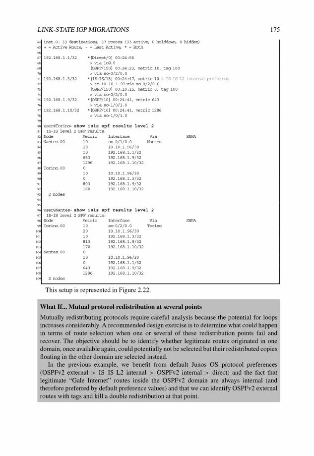
LINK-STATE IGP MIGRATIONS 175
64 inet.0: 33 destinations, 37 routes (33 active, 0 holddown, 0 hidden)65 + = Active Route, - = Last Active, * = Both66
67 192.168.1.1/32 *[Direct/0] 00:24:5668 > via lo0.069 [OSPF/150] 00:24:23, metric 10, tag 10070 > via so-0/2/0.071 192.168.1.3/32 *[IS-IS/18] 00:24:47, metric 10 # IS-IS L2 internal preferred72 > to 10.10.1.97 via so-0/2/0.073 [OSPF/150] 00:10:15, metric 0, tag 10074 > via so-0/2/0.075 192.168.1.9/32 *[OSPF/10] 00:24:41, metric 64376 > via so-1/0/1.077 192.168.1.10/32 *[OSPF/10] 00:24:41, metric 128678 > via so-1/0/1.079
80 user@Torino> show isis spf results level 281 IS-IS level 2 SPF results:82 Node Metric Interface Via SNPA83 Nantes.00 10 so-0/1/0.0 Nantes84 20 10.10.1.96/3085 10 192.168.1.1/3286 653 192.168.1.9/3287 1296 192.168.1.10/3288 Torino.00 089 10 10.10.1.96/3090 0 192.168.1.3/3291 803 192.168.1.9/3292 160 192.168.1.10/3293 2 nodes94
95
96 user@Nantes> show isis spf results level 297 IS-IS level 2 SPF results:98 Node Metric Interface Via SNPA99 Torino.00 10 so-0/2/0.0 Torino
100 20 10.10.1.96/30101 10 192.168.1.3/32102 813 192.168.1.9/32103 170 192.168.1.10/32104 Nantes.00 0105 10 10.10.1.96/30106 0 192.168.1.1/32107 643 192.168.1.9/32108 1286 192.168.1.10/32109 2 nodes
This setup is represented in Figure 2.22.
What If... Mutual protocol redistribution at several points
Mutually redistributing protocols require careful analysis because the potential for loopsincreases considerably. A recommended design exercise is to determine what could happenin terms of route selection when one or several of these redistribution points fail andrecover. The objective should be to identify whether legitimate routes originated in onedomain, once available again, could potentially not be selected but their redistributed copiesfloating in the other domain are selected instead.
In the previous example, we benefit from default Junos OS protocol preferences(OSPFv2 external > IS–IS L2 internal > OSPFv2 internal > direct) and the fact thatlegitimate “Gale Internet” routes inside the OSPFv2 domain are always internal (andtherefore preferred by default preference values) and that we can identify OSPFv2 externalroutes with tags and kill a double redistribution at that point.

176 NETWORK MERGERS AND MIGRATIONS
Nantes10.10.1.1
Torino
10.10.1.9
InvernessBasel
10.10.1.3
10.10.1.10
NSSA no−summaries 0.0.0.3
Area 0.0.0.0
policy−statement from−domain−to−ospf {
from {
protocol [ isis direct ];
route−filter 192.168.10.0/24 exact;
route−filter 192.168.1.0/24 prefix−length−range /32−/32;
}
then {
tag 100;
accept;
}
}
policy−statement from−ospf−to−domain {
term reject−redistributed {
from {
protocol ospf;
external;
tag 100;
route−filter 192.168.1.0/24 prefix−length−range /32−/32;
}
then reject;
}
term accept−native {
from {
protocol ospf;
route−filter 192.168.1.0/24 prefix−length−range /32−/32;
}
then {
tag 200;
accept;
}
}
}
OSPFv2
IS−IS
192.168.1.10 192.168.1.9
192.168.1.3 192.168.1.1
Figure 2.22: Stage two: domain separation and mutual redistribution at domain “Monsoon”.
When issuing routing restarts and other exercises, routing tables change slightly to showbackup route paths in each case, although the information in each protocol database is thesame. This happens whenever one of these paths has been considered for installation. Inany case, active paths remain the same, as shown in Listing 2.104.
Listing 2.104: Transient backup route path appearance upon mutual protocol redistribution
1 user@Torino> show route 192.168.1.0/24 table inet.02
3 inet.0: 31 destinations, 36 routes (31 active, 0 holddown, 0 hidden)4 + = Active Route, - = Last Active, * = Both5
6 192.168.1.1/32 *[IS-IS/18] 00:01:47, metric 107 > to 10.10.1.98 via so-0/1/0.08 [OSPF/150] 00:01:58, metric 0, tag 1009 > via so-0/1/0.0
10 192.168.1.3/32 *[Direct/0] 00:02:4111 > via lo0.012 [OSPF/150] 00:01:58, metric 10, tag 10013 > via so-0/1/0.014 192.168.1.9/32 *[OSPF/10] 00:02:25, metric 80315 > via at-1/2/0.100116 [IS-IS/18] 00:01:47, metric 653, tag 200, tag2 317 > to 10.10.1.98 via so-0/1/0.018 192.168.1.10/32 *[OSPF/10] 00:02:25, metric 16019 > via at-1/2/0.100120
21 user@Nantes> show route 192.168.1.0/24 table inet.022
23 inet.0: 33 destinations, 38 routes (33 active, 0 holddown, 0 hidden)24 + = Active Route, - = Last Active, * = Both25
26 192.168.1.1/32 *[Direct/0] 00:02:38

LINK-STATE IGP MIGRATIONS 177
27 > via lo0.028 [OSPF/150] 00:02:02, metric 10, tag 10029 > via so-0/2/0.030 192.168.1.3/32 *[IS-IS/18] 00:02:30, metric 1031 > to 10.10.1.97 via so-0/2/0.032 [OSPF/150] 00:02:17, metric 0, tag 10033 > via so-0/2/0.034 192.168.1.9/32 *[OSPF/10] 00:02:22, metric 64335 > via so-1/0/1.036 192.168.1.10/32 *[OSPF/10] 00:02:22, metric 128637 > via so-1/0/1.038 [IS-IS/18] 00:02:04, metric 170, tag 200, tag2 339 > to 10.10.1.97 via so-0/2/0.0
In similar scenarios, just tagging redistribution and matching those tags with therestriction to be a host address inside 192.168.1.0/24 would not be enough, becauselegitimate routes inside the OSPFv2 domain are also inside the route-filter range. Achicken-and-egg situation could be easily created upon no internal/external distinction atthe internal OSPFv2 domain or if external OSPFv2 routes were preferred against IS–ISLevel 2 internal.
2.3.6 Stage three: IS–IS protocol adaption at domain “Mistral”
Domain “Mistral” includes systems already running IS–IS Level 1 with a different authenti-cation key in a flat area. At the same time, router Male must remain in the final topology asinternal L1 system acquiring specific routing information from 192.168.10.0/24 and loopbackaddresses over both its uplinks for the sake of optimal routing, with both router Bilbao androuter Havana as L1L2 systems. Considering router Bilbao as an illustrative sample, thesituation is shown in Listing 2.105, but because this a flat L1 Area, similar visibility is grantedat router Male and router Havana.
Listing 2.105: Initial IS–IS status at Bilbao
1 user@Bilbao-re0> show configuration protocols isis2 reference-bandwidth 100g;3 level 1 {4 authentication-key "$9$ewrvL7g4ZjkPJG6ApuEhX7-"; ### SECRET-DATA5 authentication-type md5;6 wide-metrics-only;7 }8 interface at-1/2/1.0;9 interface so-1/3/1.0;
10 interface lo0.0 {11 level 1 passive;12 }13
14 user@Bilbao-re0> show isis adjacency15 Interface System L State Hold (secs) SNPA16 at-1/2/1.0 Havana 1 Up 2017 so-1/3/1.0 male-re0 1 Up 2318
19 user@Bilbao-re0> show isis database detail20 IS-IS level 1 link-state database:21
22 Havana.00-00 Sequence: 0xcd, Checksum: 0x6aca, Lifetime: 712 secs23 IS neighbor: Havana.02 Metric: 10024 IS neighbor: Bilbao-re0.00 Metric: 64325 IP prefix: 172.16.1.40/30 Metric: 643 Internal Up26 IP prefix: 172.16.1.84/30 Metric: 100 Internal Up27 IP prefix: 192.168.1.4/32 Metric: 0 Internal Up

178 NETWORK MERGERS AND MIGRATIONS
28
29 Havana.02-00 Sequence: 0xbf, Checksum: 0xf340, Lifetime: 653 secs30 IS neighbor: Havana.00 Metric: 031 IS neighbor: male-re0.00 Metric: 032
33 Bilbao-re0.00-00 Sequence: 0xcc, Checksum: 0xf7fd, Lifetime: 724 secs34 IS neighbor: Havana.00 Metric: 64335 IS neighbor: male-re0.00 Metric: 64336 IP prefix: 172.16.1.40/30 Metric: 643 Internal Up37 IP prefix: 172.16.1.76/30 Metric: 643 Internal Up38 IP prefix: 192.168.1.8/32 Metric: 0 Internal Up39
40 male-re0.00-00 Sequence: 0xc8, Checksum: 0x67ac, Lifetime: 712 secs41 IS neighbor: Havana.02 Metric: 10042 IS neighbor: Bilbao-re0.00 Metric: 64343 IP prefix: 172.16.1.76/30 Metric: 643 Internal Up44 IP prefix: 172.16.1.84/30 Metric: 100 Internal Up45 IP prefix: 192.168.1.20/32 Metric: 0 Internal Up46
47 IS-IS level 2 link-state database:48
49 Havana.00-00 Sequence: 0x9ad, Checksum: 0x1d2e, Lifetime: 228 secs50 IS neighbor: Bilbao-re0.00 Metric: 64351 IP prefix: 172.16.1.40/30 Metric: 643 Internal Up52 IP prefix: 172.16.1.76/30 Metric: 743 Internal Up53 IP prefix: 172.16.1.84/30 Metric: 100 Internal Up54 IP prefix: 192.168.1.4/32 Metric: 0 Internal Up55 IP prefix: 192.168.1.20/32 Metric: 100 Internal Up56
57 Bilbao-re0.00-00 Sequence: 0x2, Checksum: 0xb2d3, Lifetime: 722 secs58 IP prefix: 172.16.1.40/30 Metric: 63 Internal Up59 IP prefix: 172.16.1.76/30 Metric: 63 Internal Up60 IP prefix: 172.16.1.84/30 Metric: 63 Internal Up61 IP prefix: 192.168.1.4/32 Metric: 63 Internal Up62 IP prefix: 192.168.1.8/32 Metric: 0 Internal Up63 IP prefix: 192.168.1.20/32 Metric: 63 Internal Up64
65 user@Bilbao-re0> show route protocol isis table inet.066
67 inet.0: 16 destinations, 16 routes (16 active, 0 holddown, 0 hidden)68 + = Active Route, - = Last Active, * = Both69
70 172.16.1.84/30 *[IS-IS/15] 00:08:19, metric 74371 to 172.16.1.41 via at-1/2/1.072 > to 172.16.1.77 via so-1/3/1.073 192.168.1.4/32 *[IS-IS/15] 00:08:19, metric 64374 > to 172.16.1.41 via at-1/2/1.075 192.168.1.20/32 *[IS-IS/15] 00:08:19, metric 64376 > to 172.16.1.77 via so-1/3/1.0
Considering that the initial short-term objective is to integrate this L1 area in the rest ofthe domain, the objectives at this stage are summarized as follows:
• Deploy IS–IS Level 2 in router Bilbao and router Havana with the final domainsettings.
• Define route-leaking policies from Level 2 to Level 1 for optimal routing from routerMale.
Junos OS allows different parameters to be set on a per IS–IS level basis. Thus, thefinal IS–IS Level 2 authentication key and wide-metrics-only could theoretically bedirectly activated on both router Bilbao and router Havana as a previous step to integrate thisnetwork.

LINK-STATE IGP MIGRATIONS 179
However, after in-depth analysis, there is a notable drawback to this proposal: theadjacency between router Bilbao and router Havana is based on a point-to-point link. Forsuch media, IS–IS issues a joint point-to-point IIH PDU for both Level 1 and Level 2, with aunique and common TLV 10 Authentication. If authentication settings are different betweenboth levels, one of the two adjacencies will not fully form because of the authenticationmismatch.
Junos OS includes several related knobs to overcome authentication problems. However,considering that the idea is to grant reachability for all systems and avoid manipulating routerMale, the following options for the dilemma need to be evaluated:
• Keep the link between router Bilbao and router Havana as Level 1 only.
• Define the link between router Bilbao and router Havana as Level 2 only.
• Keep the link available for L1 and L2 adjacencies, but avoid authentication checksin both router Bilbao and router Havana with the no-authentication-checkknob or avoid issuing hello authentication checks per level with the no-hello-authentication knob.
• Keep the link available for L1 and L2 adjacencies but attach the TLV 10 Authen-tication with Level 2 settings to point-to-point IIH PDUs over it with the hello-authentication knob matching those settings for the Level 1 adjacency.
The first option would mean that the temporary domain would not have additionalredundancy (backbone in a ring form) and should not be chosen as an alternative for thatreason.
The second option requires more careful thinking: activating IS–IS Level 2 only overthat link means that, unless leaked by specific policies or unless manipulating ISO areaconfiguration, the transit network would not be available as a specific route for router Maleand redundancy between router Male and the other systems would be lost in the currentsetup. The rationale for this behavior resides in how Junos OS interprets backbone detectionconditions for ATTached bit setting: a system configured for IS–IS L2 goes through all L2LSPs present in the database for all reachable systems (meaning SPF calculations on IS–ISL2 information) to check whether there is at least one other area entry that does not exist inthe conglomerate of all its local L1 areas (this behavior occurs by default, without includingthe suppress-attached-bit in the configuration).
With this implementation for backbone detection and ATTached bit setting, the risk isthat at this point in the migration only Area 49.0001 is present in the domain, so movingthat connection for unique IS–IS L2 would blackhole that backup path and hide routinginformation to router Male.
Junos Tip: IS–IS ATTached bit setting conditions
Backbone detection is basically understood in Junos OS as the presence of a non-L1 areain any of the IS–IS L2 LSPs in the database. Activating IS–IS Level 2 in a domain with thesame area identifier may lead to not setting ATTached bits for internal L1 LSPs from L1L2systems.

180 NETWORK MERGERS AND MIGRATIONS
Considering the previous example from domain “Mistral”, the situation could be evenworse if both loopbacks from L1L2 systems are not injected into L1 LSPs (this could be ausual practice when aggregating loopback spaces from areas and backbone in other setups),as shown in Listing 2.106.
Listing 2.106: Lack of loopback address presence and ATTached bit in domain “Mistral”
1 [edit protocols isis]2 user@Bilbao-re0# show3 reference-bandwidth 100g;4 level 1 {5 authentication-key "$9$ewrvL7g4ZjkPJG6ApuEhX7-"; ### SECRET-DATA6 authentication-type md5;7 wide-metrics-only;8 }9 level 2 {
10 authentication-key "$9$RJehrK-ds4JDwYfz3npulKM"; ### SECRET-DATA11 authentication-type md5;12 wide-metrics-only;13 }14 interface at-1/2/1.0 {15 level 1 disable;16 }17 interface so-1/3/1.0 {18 level 2 disable;19 }20 interface lo0.0 {21 level 1 disable;22 level 2 passive;23 }24
25 user@Bilbao-re0> show isis database26 IS-IS level 1 link-state database:27 LSP ID Sequence Checksum Lifetime Attributes28 Havana.00-00 0xc9 0x1113 873 L1 L229 Havana.02-00 0xbd 0xf9e9 768 L1 L230 Bilbao-re0.00-00 0xca 0x94ee 815 L1 L231 male-re0.00-00 0xc5 0x8fee 654 L132 4 LSPs33
34 IS-IS level 2 link-state database:35 LSP ID Sequence Checksum Lifetime Attributes36 Havana.00-00 0x9ab 0xdd01 979 L1 L237 Bilbao-re0.00-00 0xce 0xcc36 815 L1 L238 2 LSPs39
40 user@male-re0> show isis database41 IS-IS level 1 link-state database:42 LSP ID Sequence Checksum Lifetime Attributes43 Havana.00-00 0xad 0xbdaa 997 L1 L244 Havana.02-00 0xab 0x21f0 998 L1 L245 Bilbao-re0.00-00 0xb0 0x8ae0 555 L1 L246 male-re0.00-00 0xb0 0x3ed6 1193 L147 4 LSPs48
49 IS-IS level 2 link-state database:50 0 LSPs51
52 user@male-re0> show route 0/053
54 inet.0: 5 destinations, 5 routes (5 active, 0 holddown, 0 hidden)55 + = Active Route, - = Last Active, * = Both56
57 172.16.1.76/30 *[Direct/0] 1d 13:24:4858 > via so-3/2/1.059 172.16.1.77/32 *[Local/0] 1d 15:55:56

LINK-STATE IGP MIGRATIONS 181
60 Local via so-3/2/1.061 172.16.1.84/30 *[Direct/0] 1d 15:55:2062 > via ge-4/2/4.063 172.16.1.85/32 *[Local/0] 1d 15:55:5264 Local via ge-4/2/4.065 192.168.1.20/32 *[Direct/0] 1d 15:56:4866 > via lo0.0
Note that router Male has neither any active IS–IS route nor default route tracking theATTached bit, because this is not set.
The third option listed for overcoming authentication problems would lead to avoidance ofany kind of authentication checks on both router Bilbao and router Havana by means of theno-authentication-check knob or skipping any kind of hello authentication checkson a per-level basis via no-hello-authentication. Both are valid approaches, but theobjective at this stage is to minimize changes and avoid any affect on the L1 systems.
The fourth option considers using TLV 10 Authentication with final settings on point-to-point IIH PDUs over this link between both systems in a common fashion for both levels. Thisscalpel-like implementation achieves our objective in a more granular fashion: LSPs, CSNPs,and PSNPs for each level will include the respectively defined authentication informationfor each level, and only IIHs for this link will include settings from Level 2 by modifyinghello authentication for Level 1. With that, IS–IS L1 and L2 adjacencies will be set upindependently, and routing information will be separately decoded for L1 and L2.
Listing 2.107 summarizes the settings for router Bilbao with this latest implementationoption, router Havana includes a similar excerpt. It is worth noting that there is no ATTachedbit set to L1 LSPs despite Level 2 being configured, because no other Areas have beenextracted from the IS–IS database. Note that this activation is completely transparent forthe current forwarding state as well, because IS–IS Level 1 routes will always be preferredover IS–IS Level 2 routes as per default protocol preference values. No routing changes areexpected by this simple activation, because changing the authentication key in Junos OS doesnot trigger an adjacency re-establishment.
Listing 2.107: IS–IS L2 activation in Bilbao with final authentication settings for Level 1 inlink to Havana
1 user@Bilbao-re0> show configuration protocols isis2 reference-bandwidth 100g;3 level 1 {4 authentication-key "$9$ewrvL7g4ZjkPJG6ApuEhX7-"; ### SECRET-DATA5 authentication-type md5;6 wide-metrics-only;7 }8 level 2 { # Additional IS-IS Level 2 authentication details9 authentication-key "$9$w2Y2oDjqPT3goF/"; ### SECRET-DATA
10 authentication-type md5;11 wide-metrics-only;12 }13 interface at-1/2/1.0 {14 level 1 { # Authentication settings from Level 215 hello-authentication-key "$9$hl0SyeLX-bYore4Z"; ### SECRET-DATA16 hello-authentication-type md5;17 }18 }19 interface so-1/3/1.0 {20 level 2 disable;21 }

182 NETWORK MERGERS AND MIGRATIONS
22 interface lo0.0 {23 level 1 passive;24 level 2 passive;25 }26
27 user@Bilbao-re0> show route protocol isis table inet.028
29 inet.0: 16 destinations, 16 routes (16 active, 0 holddown, 0 hidden)30 + = Active Route, - = Last Active, * = Both31
32 172.16.1.84/30 *[IS-IS/15] 01:35:13, metric 74333 to 172.16.1.41 via at-1/2/1.034 > to 172.16.1.77 via so-1/3/1.035 192.168.1.4/32 *[IS-IS/15] 01:35:13, metric 64336 > to 172.16.1.41 via at-1/2/1.037 192.168.1.20/32 *[IS-IS/15] 03:56:58, metric 64338 > to 172.16.1.77 via so-1/3/1.039
40 user@Bilbao-re0> show isis database41 # Same IS-IS DB as without authentication42 IS-IS level 1 link-state database:43 LSP ID Sequence Checksum Lifetime Attributes44 Havana.00-00 0xe1 0x6db6 328 L1 L245 Havana.02-00 0xd1 0x1770 328 L1 L246 Bilbao-re0.00-00 0xdf 0x47c0 423 L1 L247 male-re0.00-00 0xda 0x507c 1011 L148 4 LSPs49
50 IS-IS level 2 link-state database:51 LSP ID Sequence Checksum Lifetime Attributes52 Havana.00-00 0xa 0x16ec 429 L1 L253 Bilbao-re0.00-00 0x16 0xfc2b 694 L1 L254 2 LSPs55
56 user@Bilbao-re0> show isis database detail57 # Level 2 contains redundant routing information58 IS-IS level 1 link-state database:59
60 Havana.00-00 Sequence: 0xe2, Checksum: 0x4405, Lifetime: 1195 secs61 IS neighbor: Havana.02 Metric: 10062 IS neighbor: Bilbao-re0.00 Metric: 64363 IP prefix: 172.16.1.40/30 Metric: 643 Internal Up64 IP prefix: 172.16.1.84/30 Metric: 100 Internal Up65 IP prefix: 192.168.1.4/32 Metric: 0 Internal Up66
67 Havana.02-00 Sequence: 0xd2, Checksum: 0xa314, Lifetime: 1195 secs68 IS neighbor: Havana.00 Metric: 069 IS neighbor: male-re0.00 Metric: 070
71 Bilbao-re0.00-00 Sequence: 0xdf, Checksum: 0x47c0, Lifetime: 413 secs72 IS neighbor: Havana.00 Metric: 64373 IS neighbor: male-re0.00 Metric: 64374 IP prefix: 172.16.1.40/30 Metric: 643 Internal Up75 IP prefix: 172.16.1.76/30 Metric: 643 Internal Up76 IP prefix: 192.168.1.8/32 Metric: 0 Internal Up77
78 male-re0.00-00 Sequence: 0xda, Checksum: 0x507c, Lifetime: 1001 secs79 IS neighbor: Havana.02 Metric: 10080 IS neighbor: Bilbao-re0.00 Metric: 64381 IP prefix: 172.16.1.76/30 Metric: 643 Internal Up82 IP prefix: 172.16.1.84/30 Metric: 100 Internal Up83 IP prefix: 192.168.1.20/32 Metric: 0 Internal Up84
85 IS-IS level 2 link-state database:86
87 Havana.00-00 Sequence: 0xa, Checksum: 0x16ec, Lifetime: 418 secs88 IS neighbor: Bilbao-re0.00 Metric: 64389 IP prefix: 172.16.1.40/30 Metric: 643 Internal Up90 IP prefix: 172.16.1.76/30 Metric: 743 Internal Up

LINK-STATE IGP MIGRATIONS 183
91 IP prefix: 172.16.1.84/30 Metric: 100 Internal Up92 IP prefix: 192.168.1.4/32 Metric: 0 Internal Up93 IP prefix: 192.168.1.8/32 Metric: 643 Internal Up94 IP prefix: 192.168.1.20/32 Metric: 100 Internal Up95
96 Bilbao-re0.00-00 Sequence: 0x16, Checksum: 0xfc2b, Lifetime: 684 secs97 IS neighbor: Havana.00 Metric: 64398 IP prefix: 172.16.1.40/30 Metric: 643 Internal Up99 IP prefix: 172.16.1.76/30 Metric: 643 Internal Up
100 IP prefix: 172.16.1.84/30 Metric: 743 Internal Up101 IP prefix: 192.168.1.4/32 Metric: 643 Internal Up102 IP prefix: 192.168.1.8/32 Metric: 0 Internal Up103 IP prefix: 192.168.1.20/32 Metric: 643 Internal Up
Once the Level 2 adjacency has been properly set, route-leaking policies for optimalrouting from and to router Male can be crafted at this point to prepare backbone connection.In the previous Listing 2.107, loopback interface addresses were injected in both L1 and L2LSPs for optimal routing purposes. This simplifies route-leaking policies at L1L2 systems bydefault, because it will just be necessary to match protocol IS–IS and Level 2, together withproper route-filtering, to inject such information to Level 1 systems, and there is no need tomatch then direct routes.
Listing 2.108 illustrates policy definition, application, and effects from router Bilbao’sperspective. Note that router Bilbao is not leaking Havana’s loopback address, and viceversa, in L1 LSPs at this point, because we enforce that only IS–IS Level 2 routes arematched and such loopback addresses are preferred as IS–IS Level 1 routes. Despite thisleaking implementation, the ATTached bit remains unset and router Male has no default routepointing to any of both L1L2 systems.
Listing 2.108: IS–IS L2 to L1 leaking policy application and effects in Bilbao
1 [edit policy-options policy-statement leak-loopbacks-to-l1]2 user@Bilbao-re0# show3 from {4 protocol isis; # Only match protocol isis5 level 2; # Only match L2 routes6 route-filter 192.168.1.0/24 prefix-length-range /32-/32;7 route-filter 192.168.10.0/24 exact;8 }9 to level 1;
10 then {11 tag 300;12 accept;13 }14
15 [edit]16 user@Bilbao-re0# set protocols isis export leak-loopbacks-to-l117
18 user@Bilbao-re0> show isis database detail19 # No changes in current IS-IS database yet20 IS-IS level 1 link-state database:21
22 Havana.00-00 Sequence: 0xe6, Checksum: 0xaafd, Lifetime: 1069 secs23 IS neighbor: Havana.02 Metric: 10024 IS neighbor: Bilbao-re0.00 Metric: 64325 IP prefix: 172.16.1.40/30 Metric: 643 Internal Up26 IP prefix: 172.16.1.84/30 Metric: 100 Internal Up27 IP prefix: 192.168.1.4/32 Metric: 0 Internal Up28
29 Havana.02-00 Sequence: 0xd5, Checksum: 0x1470, Lifetime: 1061 secs30 IS neighbor: Havana.00 Metric: 031 IS neighbor: male-re0.00 Metric: 032

184 NETWORK MERGERS AND MIGRATIONS
33 Bilbao-re0.00-00 Sequence: 0xe5, Checksum: 0x90f6, Lifetime: 897 secs34 IS neighbor: Havana.00 Metric: 64335 IS neighbor: male-re0.00 Metric: 64336 IP prefix: 172.16.1.40/30 Metric: 643 Internal Up37 IP prefix: 172.16.1.76/30 Metric: 643 Internal Up38 IP prefix: 192.168.1.8/32 Metric: 0 Internal Up39
40 male-re0.00-00 Sequence: 0xdd, Checksum: 0x2a66, Lifetime: 825 secs41 IS neighbor: Havana.02 Metric: 10042 IS neighbor: Bilbao-re0.00 Metric: 64343 IP prefix: 172.16.1.76/30 Metric: 643 Internal Up44 IP prefix: 172.16.1.84/30 Metric: 100 Internal Up45 IP prefix: 192.168.1.20/32 Metric: 0 Internal Up46
47 IS-IS level 2 link-state database:48
49 Havana.00-00 Sequence: 0xf, Checksum: 0x5be3, Lifetime: 1069 secs50 IS neighbor: Bilbao-re0.00 Metric: 64351 IP prefix: 172.16.1.40/30 Metric: 643 Internal Up52 IP prefix: 172.16.1.76/30 Metric: 743 Internal Up53 IP prefix: 172.16.1.84/30 Metric: 100 Internal Up54 IP prefix: 192.168.1.4/32 Metric: 0 Internal Up55 IP prefix: 192.168.1.8/32 Metric: 643 Internal Up56 IP prefix: 192.168.1.20/32 Metric: 100 Internal Up57
58 Bilbao-re0.00-00 Sequence: 0x1b, Checksum: 0x47e8, Lifetime: 896 secs59 IS neighbor: Havana.00 Metric: 64360 IP prefix: 172.16.1.40/30 Metric: 643 Internal Up61 IP prefix: 172.16.1.76/30 Metric: 643 Internal Up62 IP prefix: 172.16.1.84/30 Metric: 743 Internal Up63 IP prefix: 192.168.1.4/32 Metric: 643 Internal Up64 IP prefix: 192.168.1.8/32 Metric: 0 Internal Up65 IP prefix: 192.168.1.20/32 Metric: 643 Internal Up
This situation is illustrated in Figure 2.23.
49.0001.1921.6800.1020.00policy−statement leak−loopbacks−to−l1 {
from {
protocol isis;
level 2;
route−filter 192.168.1.0/24 prefix−length−range /32−/32;
route−filter 192.168.10.0/24 exact;
}
to level 1;
then {
tag 300;
accept;
}
}
Male
Bilbao
Havana192.168.1.4
192.168.1.20
192.168.1.8
49.0001.1921.6800.1004.00
L1
L1
L1
49.0001.1921.6800.1008.00
L2
interface at−1/2/1.0 {
level 1 {
hello−authentication−key "$9$hl0SyeLX−bYore4Z";
hello−authentication−type md5;
}
}
Figure 2.23: Stage three: IS–IS L2 activation and redistribution at domain “Mistral”.

LINK-STATE IGP MIGRATIONS 185
2.3.7 Stage four: Domain interconnection via IS–IS Level 2
All three domains have been prepared to advertise and receive public loopback addresses.At this point, border systems from each domain just need to activate IS–IS Level 2 over thenewly acquired leased lines with the intention of stitching together domains and allowingroute propagation.
Before effectively merging domains, another factor should be evaluated: link costs.Domain “Monsoon” inherits reference-bandwidth 100 g from OSPFv2 and domain“Mistral” includes the same reference per original definition, but domain “Cyclone” hasmirrored in IS–IS reference-bandwidth 10 g from OSPFv2.
Under current circumstances, metric values are an order of magnitude lower in domain“Cyclone” than automatically derived values from other domains. Keeping the same schemecould lead to routing asymmetries, although all outgoing and incoming costs to this domainwill be of the same magnitude. While it makes sense to keep the same reference bandwidthinternally in domain “Cyclone”, it is recommended to align costs with other leased lines toand from other domains to ease operation and troubleshooting.
In addition, the domain interconnect topology results in router Skopie being single-homedto router Livorno as internal connection in domain “Cyclone”, but this link becomes part ofthe internal ring that can act as transit for traffic between other remote end points. Modifyingthe cost of that link to be aligned with the reference bandwidth for other domains and externalleased lines would diverge from the current OSPFv2 link cost, but would not influence routingdecisions internally in that domain (as it is single-homed).
The configuration snippet in Listing 2.109 illustrates the changes needed in router Livornoto interconnect domain “Cyclone” with domain “Mistral” over a specific leased line,together with the ad-hoc metric setting for that link and the interface to router Skopie. Theconfiguration changes are similar in all border systems for all external connections, apartfrom particular link metrics. It is important to note that IS–IS Level 1 should be explicitlydisabled from those links to avoid any IS–IS Level 1 adjacency that could lead to undesiredeffects.
Listing 2.109: IS–IS L2 deployment over leased-line and metric adaption in router Livornofor domain interconnection
1 [edit protocols isis]2 user@Nantes# set interface so-0/0/1.0 level 1 disable3 [edit protocols isis]4 user@Livorno# set interface so-0/0/1.0 level 2 metric 6435 [edit protocols isis]6 user@Livorno# set interface so-0/0/0.0 level 2 metric 6437 [edit]8 user@Livorno# set interfaces so-0/0/1.0 family iso9
10 user@Livorno> show isis adjacency11 Interface System L State Hold (secs) SNPA12 ge-0/2/0.0 Barcelona-re0 2 Up 23 0:14:f6:84:8c:bc13 ge-1/3/0.0 honolulu-re0 2 Up 8 0:17:cb:d3:2f:1614 so-0/0/0.0 Skopie 2 Up 2315 so-0/0/1.0 Havana 2 Up 2216
17 user@Livorno> show isis database18 IS-IS level 1 link-state database:19 LSP ID Sequence Checksum Lifetime Attributes20 Livorno.00-00 0x94 0x4bdd 1132 L1 L2 Attached21 1 LSPs22

186 NETWORK MERGERS AND MIGRATIONS
23 IS-IS level 2 link-state database:24 LSP ID Sequence Checksum Lifetime Attributes25 Nantes.00-00 0x79 0x5476 1176 L1 L226 Nantes.02-00 0x3 0x2fbc 1176 L1 L227 Skopie.00-00 0xa2 0xecd 1153 L1 L228 Torino.00-00 0x7c 0xc3b9 678 L1 L229 Havana.00-00 0x1e 0xd0c4 899 L1 L230 Livorno.00-00 0xa0 0xcd10 1139 L1 L231 Livorno.02-00 0x93 0x924e 1132 L1 L232 Barcelona-re0.00-00 0x95 0xe531 838 L1 L233 Bilbao-re0.00-00 0x31 0x84cb 1190 L1 L234 honolulu-re0.00-00 0x94 0xfc5f 550 L1 L235 honolulu-re002-00 0x92 0xc68f 695 L1 L236 honolulu-re003-00 0x91 0x656f 1036 L1 L237 12 LSPs
Because domains are interconnected, IS–IS Level 2 routing information is flooded. Beforeproceeding to a preliminary interconnect analysis, router Lille needs to be linked to thecurrently built topology. At this stage, note that router Livorno is setting ATTached bitbecause it is detecting an external area in its IS–IS Level 2 Database, namely 49.0003.
2.3.8 Stage five: Integration of router Lille in the IS–IS domain
As per design prerequisite, router Lille needs to be connected to both router Livorno androuter Havana via an IS–IS Level 1 adjacency without modifying its area identifier. RouterLivorno’s Net-ID includes Area ID 49.0003, but router Havana was previously in Area49.0001.
Also, prefix leaking is needed for optimal routing; the exact same policy defined inListing 2.108 can be used for this. This policy is already implemented in router Havanafor the internal Area 49.0001, but needs to be addressed in router Livorno. Also, this systemis part of a domain with a different reference-bandwidth, and it would be preferableto adapt metric costs to the same value as router Havana to have optimal routing from remoteend points.
Router Lille is a very sensitive system with direct connections to the NOC and to allmanagement systems, and as a protection mechanism, no default route should be installed asa consequence of any IS–IS ATTached bits.
On top of all these obvious requirements, another subtle situation needs careful thought:router Havana is already L1L2 system for another L1 area with different authenticationsettings than the final key values. Authentication keys for all IS–IS PDUs cannot beconfigured on a per-area basis, but on a per-level basis, which means that modifying thesevalues would have further implications inside the domain “Mistral”. Effectively, because bothArea 49.0001 and Area 49.0003 are included in IS–IS Level 1 adjacencies to router Havana,both areas are stitched together at that point.
The available options in this stage are the following:
• Migrate the entire Area 49.0001 Level 1 authentication key to the final value, Aeris.
• Use the loose-authentication-check knob at router Livorno and routerHavana and do not implement any authentication on router Lille.
• Implement Area 49.0001 authentication settings at this Area 49.0003 in router Lille,router Livorno, and router Havana. This will need to be migrated again at a later step.

LINK-STATE IGP MIGRATIONS 187
While the first option is the realistic final scenario, the intent at this point is not tomodify the authentication settings, because this would require migrating authentication forall systems inside the domain “Mistral” (imagine a much larger domain than this simplisticcase study).
The second option allows authentication checks on router Havana for all currently existingadjacencies protected with authentication, except for the newest one to router Lille, and it alsoallows the final authentication settings on router Livorno to be configured with only minimalconfiguration of loose authentication checks in each case. However, IS–IS Level 1 is actuallynot constrained only to these three systems, because router Havana effectively connects twodifferent areas together in the same Level 1. This means that the scope of authenticationparameterization really goes beyond router Havana up to router Male and router Bilbao (orto a more populated area as a more realistic scenario). While a given combination of looseand no authentication checks can provide the intended result, being able to fully decode LSPsin one L1 system but not on the other is certainly not as optimal for troubleshooting as thenext option.
Despite going in an opposite direction to the final scenario, the preference here is thethird option provided that router Livorno is not connected to any other L1 area and thatthis modification just affects router Lille and router Livorno at this time. A step back cansometimes be the best approach to move forward!
All these requirements can be summarized in the following migration guidelines:
• Add an Area ID 49.0003 derived Net-ID on router Havana and activate the IS–IS L1adjacency towards router Lille with the same old authentication settings.
• Implement L2-to-L1 leaking policies in router Livorno and adapt the link costcalculation. Deploy authentication settings from the domain “Mistral” in routerLivorno for IS–IS Level 1.
• Consider that some active loopback routes in router Livorno are still OSPFv2 routesand would need to be leaked down as well for optimal routing purposes.
• Activate L1 adjacencies over the shared broadcast domain and ignore ATTached bitsetting in router Lille. Deploy authentication settings from domain “Mistral” in routerLille for IS–IS Level 1.
Adding a new area identifier to an existing intermediate system is a completely gracefuloperation in Junos OS. Listing 2.110 summarizes this simple configuration step together withIS–IS L1 activation for the Ethernet link to router Lille.
Listing 2.110: IS–IS L1 adjacency activation steps at Havana
1 [edit]2 user@Havana# set interfaces lo0.0 family iso address 49.0003.1921.6800.1004.003 [edit]4 user@Havana# set interfaces fe-0/3/0.0 family iso5 [edit]6 user@Havana# set protocols isis interface fe-0/3/0.0 level 2 disable
On router Livorno a similar route-leaking policy needs to be defined and implemented,together with parallel link metric setting. Likewise, IS–IS Level 1 includes temporaryauthentication values from domain “Mistral” at this stage. Similarly to our previous policy in

188 NETWORK MERGERS AND MIGRATIONS
router Havana, the intent is not to match direct routes for leaking to IS–IS Level 1, but rather,the loopback interface is included as passive in the configuration.
However, there is an additional circumstance at this stage in the migration. Router Livornohas fully deployed IS–IS, but this protocol remains unpreferred against OSPFv2 internal orexternal routes. As Junos OS export policies look in link-state IGPs at active versions of aroute in the routing table, not at link-state IGP databases, it is necessary to add OSPFv2 activeroutes in this combination, as long as OSPFv2 remains preferred in domain “Cyclone”. Allthese changes are illustrated in Listing 2.111.
Listing 2.111: IS–IS L1 adjacency activation and leaking steps at Livorno
1 [edit policy-options policy-statement leak-loopbacks-to-l1]2 user@Livorno# show3 term isis {4 from {5 protocol isis; # IS-IS active loopback routes6 level 2;7 route-filter 192.168.1.0/24 prefix-length-range /32-/32;8 route-filter 192.168.10.0/24 exact;9 }
10 to level 1;11 then {12 tag 300;13 accept;14 }15 }16 term ospf {17 from {18 protocol ospf; # Currently OSPFv2 active routes19 route-filter 192.168.1.0/24 prefix-length-range /32-/32;20 route-filter 192.168.10.0/24 exact;21 }22 to level 1; # Only to single existing L1 adjacency23 then {24 tag 300;25 accept;26 }27 }28 [edit]29 user@Livorno# set interfaces fe-0/3/0.0 family iso30 [edit]31 user@Livorno# set protocols isis interface fe-0/3/0.0 level 2 disable32 [edit]33 user@Livorno# delete protocols isis interface lo0.0 level 1 disable34 [edit]35 user@Livorno# set protocols isis interface lo0.0 level 1 passive36 [edit]37 user@Livorno# set protocols isis export leak-loopbacks-to-l138 [edit]39 user@Livorno# set protocols isis level 1 authentication-key "Mistral"40 [edit]41 user@Livorno# set protocols isis interface fe-0/3/0.0 level 1 metric 1000
Finally, IS–IS Level 1 with similar wide-metrics-only and domain “Mistral”authentication key is implemented in router Lille, together with explicitly ignoring theATTached bit setting with respect to default route installation, as shown in Listing 2.112.
Listing 2.112: IS–IS L1 adjacency configuration at Lille
1 user@Lille> show configuration protocols isis2 reference-bandwidth 100g;3 ignore-attached-bit;4 level 2 disable;

LINK-STATE IGP MIGRATIONS 189
5 level 1 {6 authentication-key "$9$M2887daJDkmTUjCuOBSyNdb"; ### SECRET-DATA7 authentication-type md5;8 wide-metrics-only;9 }
10 interface fe-0/3/0.0 {11 level 2 disable;12 }13 interface lo0.0 {14 level 2 disable;15 }
As expected, both Level 1 Areas are stitched together on router Havana and router Lillehas full visibility now on all loopback addresses and the external network range. This scenariois illustrated in Figure 2.24.
policy−statement leak−loopbacks−to−l1 {
from {
protocol isis;
level 2;
route−filter 192.168.1.0/24 prefix−length−range /32−/32;
route−filter 192.168.10.0/24 exact;
}
to level 1;
then {
tag 300;
accept;
}
}
Male
Bilbao
Havana192.168.1.4
192.168.1.20
192.168.1.8
49.0001.1921.6800.1004.00
49.0003.1921.6800.1004.00
L1
L1
L1
49.0001.1921.6800.1008.00
49.0001.1921.6800.1020.00
L2
interface at−1/2/1.0 {
level 1 {
hello−authentication−key "$9$hl0SyeLX−bYore4Z";
hello−authentication−type md5;
}
}
Livorno192.168.1.6
Lille192.168.1.5
49.0003.1921.6800.1006.00
L2
L2L2
L1
49.0003.1921.6800.1005.00
policy−statement leak−loopbacks−to−l1 {
term isis {
from {
protocol isis;
level 2;
route−filter 192.168.1.0/24 prefix−length−range /32−/32;
route−filter 192.168.10.0/24 exact;
}
to level 1;
then {
tag 300;
accept;
}
}
}
term ospf {
from {
protocol ospf;
route−filter 192.168.1.0/24 prefix−length−range /32−/32;
route−filter 192.168.10.0/24 exact;
}
to level 1;
then {
tag 300;
accept;
}
}
}
Figure 2.24: Stage five: IS–IS L1 Area merging and activation at router Lille.
Nevertheless, the route injection policy from OSPFv2 at router Livorno introducesanother change when compared with the previous IS–IS database state. OSPFv2 routesare preferred and redistributed into IS–IS Level 1 with wide-metrics-only. All othersystems attached to this merged Level 1 prefer those injected routes via Level 1 versus theLevel 2 version natively present in their intended Level 2 LSPs. This situation also occursbecause of the lack of distinction between internal and external prefixes in Level 1 withthat knob. Note also that prefixes injected from OSPFv2 into IS–IS Level 1 do not havethe Up/Down bit set as per [RFC3784], as opposed to prefixes leaked from Level 2. As aresult, those prefixes could be eligible for further redistribution to Level 2 at some otherL1L2 systems.
Although this situation could initially appear to be counterintuitive, this setup properlyhandles forwarding decisions at this transient point in the migration. From the point of viewof metrics, this setup is closer to the desired behavior as well, in this case providing a backup

190 NETWORK MERGERS AND MIGRATIONS
path through IS–IS Level 1 during the transition, until OSPFv2 is removed from the domain“Cyclone”. As a result, no further fine-tuning is required at this point.
This scenario is shown in Listing 2.113 from router Lille’s perspective. Lines 39, 41, 42,45, and 46 show how the Up/Down bit is not set in prefixes injected by router Livorno, beingpreferred in domain “Cyclone” as OSPFv2 routes.
Listing 2.113: IS–IS L1 adjacency activation results at Lille
1 user@Lille> show isis adjacency2 Interface System L State Hold (secs) SNPA3 fe-0/3/0.0 Havana 1 Up 6 0:90:69:b4:bc:5d4 fe-0/3/0.0 Livorno 1 Up 20 0:14:f6:85:40:5d5
6 user@Lille> show isis database detail7 IS-IS level 1 link-state database:8
9 Havana.00-00 Sequence: 0xc, Checksum: 0x81f1, Lifetime: 831 secs10 IS neighbor: Havana.02 Metric: 100011 IS neighbor: Havana.03 Metric: 10012 IS neighbor: Bilbao-re0.00 Metric: 64313 IP prefix: 172.16.1.40/30 Metric: 643 Internal Up # Up/Down bit not set14 IP prefix: 172.16.1.84/30 Metric: 100 Internal Up # Up/Down bit not set15 IP prefix: 172.16.100.0/24 Metric: 1000 Internal Up # Up/Down bit not set16 IP prefix: 192.168.1.1/32 Metric: 743 Internal Down17 IP prefix: 192.168.1.3/32 Metric: 903 Internal Down18 IP prefix: 192.168.1.4/32 Metric: 0 Internal Up # Up/Down bit not set19 IP prefix: 192.168.1.9/32 Metric: 1386 Internal Down20 IP prefix: 192.168.1.10/32 Metric: 2029 Internal Down21
22 Havana.02-00 Sequence: 0x2, Checksum: 0x3192, Lifetime: 632 secs23 IS neighbor: Havana.00 Metric: 024 IS neighbor: Livorno.00 Metric: 025
26 Havana.03-00 Sequence: 0x2, Checksum: 0x6922, Lifetime: 706 secs27 IS neighbor: Havana.00 Metric: 028 IS neighbor: male-re0s.00 Metric: 029
30 Lille.00-00 Sequence: 0xeb, Checksum: 0x668b, Lifetime: 674 secs31 IS neighbor: Havana.03 Metric: 100032 IP prefix: 172.16.100.0/24 Metric: 1000 Internal Up33 IP prefix: 192.168.1.5/32 Metric: 0 Internal Up34
35 Livorno.00-00 Sequence: 0xd, Checksum: 0xff42, Lifetime: 829 secs36 IS neighbor: Havana.02 Metric: 100037 IP prefix: 172.16.100.0/24 Metric: 1000 Internal Up38 IP prefix: 192.168.1.1/32 Metric: 1286 Internal Down39 IP prefix: 192.168.1.2/32 Metric: 64 Internal Up # From OSPFv240 IP prefix: 192.168.1.3/32 Metric: 1446 Internal Down41 IP prefix: 192.168.1.6/32 Metric: 0 Internal Up # From OSPFv242 IP prefix: 192.168.1.7/32 Metric: 10 Internal Up # From OSPFv243 IP prefix: 192.168.1.9/32 Metric: 1929 Internal Down44 IP prefix: 192.168.1.10/32 Metric: 2572 Internal Down45 IP prefix: 192.168.1.21/32 Metric: 10 Internal Up # From OSPFv246 IP prefix: 192.168.10.0/24 Metric: 0 Internal Up # From OSPFv247
48 Bilbao-re0.00-00 Sequence: 0x13, Checksum: 0xafa5, Lifetime: 829 secs49 IS neighbor: Havana.00 Metric: 64350 IS neighbor: male-re0.00 Metric: 64351 IP prefix: 172.16.1.40/30 Metric: 643 Internal Up52 IP prefix: 172.16.1.76/30 Metric: 643 Internal Up53 IP prefix: 192.168.1.1/32 Metric: 100 Internal Down54 IP prefix: 192.168.1.3/32 Metric: 260 Internal Down55 IP prefix: 192.168.1.8/32 Metric: 0 Internal Up56 IP prefix: 192.168.1.9/32 Metric: 743 Internal Down57 IP prefix: 192.168.1.10/32 Metric: 1386 Internal Down58
59 male-re0.00-00 Sequence: 0x4, Checksum: 0x7c87, Lifetime: 552 secs

LINK-STATE IGP MIGRATIONS 191
60 IS neighbor: Havana.03 Metric: 10061 IS neighbor: Bilbao-re0.00 Metric: 64362 IP prefix: 172.16.1.76/30 Metric: 643 Internal Up63 IP prefix: 172.16.1.84/30 Metric: 100 Internal Up64 IP prefix: 192.168.1.20/32 Metric: 0 Internal Up65
66 IS-IS level 2 link-state database:67
68 user@Lille> show route protocol isis table inet.069
70 inet.0: 36 destinations, 36 routes (36 active, 0 holddown, 0 hidden)71 + = Active Route, - = Last Active, * = Both
Junos Tip: IS–IS Up/Down bit setting conditions
As per [RFC3784], the Up/Down bit is preserved in TLV 135 Extended IP Reachability toavoid routing loops from forming when transitioning IS–IS levels. However, [RFC3784]enforces that this bit SHALL be set to 0 when a prefix is first injected into IS–IS.
When deploying a ships-in-the-night model between IGPs and exporting routes froma given protocol into IS–IS Level 1, Junos OS considers them to be brand new for IS–ISand hence the bit is not set. This behavior happens even when IS–IS Level 2 is present onthe systems and such prefixes are included in TLVs 135 Extended IP Reachability fromLevel 2 LSPs, but are not selected as active paths.
Extra care must be taken because when those leaked internal prefixes are eligible for L2default propagation at other exit points of a Level 1 area and after that, they are eligibleagain for leaking to other L1 areas. This is not necessarily dangerous and can achieve thedesired effect as in this example, but it indirectly transits down hierarchy boundaries twice:first when injected from active OSPFv2 and second when leaked from Level 2 to Level 1at some other L1L2 system.
2.3.9 Stage six: Global connectivity verification
After all respective actions have been undertaken to cope with the initial requirements to haveunified management on all networks and before a full system integration, as many tests asneeded must be issued on all systems to ensure full end-to-end visibility before moving on tothe next migration stage.
Considering router Livorno as a representative system of domain “Cyclone”, Listing 2.114depicts different checks and tests to confirm our objectives. Forwarding testing has not beenincluded here for the sake of brevity. The following items are remarkable from these tests:
• IS–IS L1 database includes all L1 LSPs from merged L1 Areas 49.0001 and 49.0003(starting from Line 2).
• No ATTached bit is set at any L1 LSPs in the IS–IS L1 database because both areas aremerged and reachable via IS–IS Level 1 (starting from Line 2).
• Level 2 LSPs are visible for all domain “Cyclone” systems, along with border routersfrom other domains (starting from Line 13).
• The OSPFv2 Database remains the same as before the migration in domain “Cyclone”(starting from Line 31).

192 NETWORK MERGERS AND MIGRATIONS
• OSPFv2 routes are preferred for all internal domain “Cyclone” destinations, including192.168.10.0/24 (starting from Line 58).
• All destinations external to domain “Cyclone” are reachable via IS–IS L1 or L2 withmodified protocol preferences (starting from Line 73).
• Leaking from OSPFv2 is performed for all domain “Cyclone” systems to IS–IS Level 1Area.
• The difference between TED information injected by OSPFv2 and IS–IS refers to ourwell-known decision to adapt costs for the link between router Livorno and routerSkopie (Lines 128 and 134 for the same link).
• Forwarding to all destinations from the corresponding loopback addresses works,following optimal paths.
Listing 2.114: Initial domain integration tests at Livorno
1 user@Livorno> show isis database2 IS-IS level 1 link-state database:3 LSP ID Sequence Checksum Lifetime Attributes4 Havana.00-00 0x113 0x276 485 L1 L25 Havana.02-00 0xf2 0xf638 632 L1 L26 Havana.03-00 0xc 0x194 632 L1 L27 Lille.00-00 0xef 0x7fd0 458 L18 Livorno.00-00 0xab 0xb3d7 665 L1 L29 Bilbao-re0.00-00 0x113 0xe49f 553 L1 L2
10 male-re0.00-00 0xf8 0xf3c3 603 L111 7 LSPs12
13 IS-IS level 2 link-state database:14 LSP ID Sequence Checksum Lifetime Attributes15 Nantes.00-00 0x87 0x557a 1109 L1 L216 Nantes.02-00 0x10 0xd225 549 L1 L217 Skopie.00-00 0xb0 0x7cbd 1163 L1 L218 Torino.00-00 0x8a 0x5801 385 L1 L219 Havana.00-00 0x37 0x95df 1147 L1 L220 Livorno.00-00 0xbd 0xaa83 665 L1 L221 Livorno.02-00 0xa2 0x1002 817 L1 L222 Barcelona-re0.00-00 0xa3 0x27a5 819 L1 L223 Bilbao-re0.00-00 0x42 0x41e3 984 L1 L224 honolulu-re0.00-00 0xa2 0x6629 505 L1 L225 honolulu-re002-00 0xa0 0x9ce7 933 L1 L226 honolulu-re003-00 0x9f 0x8086 1186 L1 L227 12 LSPs28
29 user@Livorno> show ospf database30
31 OSPF database, Area 0.0.0.032 Type ID Adv Rtr Seq Age Opt Cksum Len33 Router 192.168.1.2 192.168.1.2 0x8000005f 629 0x22 0x3195 6034 Router *192.168.1.6 192.168.1.6 0x8000042d 1283 0x22 0xd94d 9635 Router 192.168.1.7 192.168.1.7 0x80000619 642 0x22 0x2d48 6036 Router 192.168.1.21 192.168.1.21 0x80000093 300 0x22 0x305d 6037 Network 172.16.1.53 192.168.1.7 0x8000006d 942 0x22 0x3e4c 3238 Network 172.16.1.90 192.168.1.21 0x8000005d 600 0x22 0x2336 3239 Network 172.16.1.105 192.168.1.21 0x8000005c 900 0x22 0x9cad 3240 OpaqArea 1.0.0.1 192.168.1.2 0x8000005a 2173 0x22 0x2fa 2841 OpaqArea*1.0.0.1 192.168.1.6 0x800003da 779 0x22 0x869 2842 OpaqArea 1.0.0.1 192.168.1.7 0x800005e2 342 0x22 0xf56f 2843 OpaqArea 1.0.0.1 192.168.1.21 0x80000082 2100 0x22 0xfdb0 2844 OpaqArea 1.0.0.3 192.168.1.2 0x80000056 1429 0x22 0xfbf5 13645 OpaqArea*1.0.0.3 192.168.1.6 0x8000004b 2265 0x22 0xe313 124

LINK-STATE IGP MIGRATIONS 193
46 OpaqArea 1.0.0.3 192.168.1.7 0x8000006b 42 0x22 0x7c57 12447 OpaqArea 1.0.0.3 192.168.1.21 0x8000007e 1500 0x22 0x4172 12448 OpaqArea*1.0.0.4 192.168.1.6 0x80000015 1783 0x22 0x8e98 13649 OpaqArea 1.0.0.4 192.168.1.7 0x8000006e 1542 0x22 0x20fa 12450 OpaqArea 1.0.0.4 192.168.1.21 0x8000007f 1800 0x22 0xd7d9 12451 OpaqArea*1.0.0.5 192.168.1.6 0x80000053 280 0x22 0x70c4 12452 OSPF AS SCOPE link state database53 Type ID Adv Rtr Seq Age Opt Cksum Len54 Extern 192.168.10.0 192.168.1.7 0x80000051 1242 0x22 0x37a 3655 Extern 192.168.10.0 192.168.1.21 0x80000035 1200 0x22 0x1b84 3656
57 user@Livorno> show route protocol ospf table inet.0 terse58
59 inet.0: 42 destinations, 48 routes (41 active, 0 holddown, 1 hidden)60 + = Active Route, - = Last Active, * = Both61
62 A Destination P Prf Metric 1 Metric 2 Next hop AS path63 172.16.1.32/30 O 10 64 >so-0/0/0.064 * 172.16.1.104/30 O 10 1010 172.16.1.5365 >172.16.1.9066 * 192.168.1.2/32 O 10 64 >so-0/0/0.067 * 192.168.1.7/32 O 10 10 >172.16.1.5368 * 192.168.1.21/32 O 10 10 >172.16.1.9069 * 192.168.10.0/24 O 150 0 >172.16.1.5370 * 224.0.0.5/32 O 10 1 MultiRecv71
72 user@Livorno> show route protocol isis table inet.0 terse73
74 inet.0: 42 destinations, 48 routes (41 active, 0 holddown, 1 hidden)75 + = Active Route, - = Last Active, * = Both76
77 A Destination P Prf Metric 1 Metric 2 Next hop AS path78 * 10.10.1.96/30 I 158 1446 >172.16.1.3379 * 172.16.1.0/30 I 158 1286 >172.16.1.3380 * 172.16.1.4/30 I 158 1386 >172.16.1.3381 172.16.1.3782 * 172.16.1.40/30 I 155 1643 >172.16.100.183 * 172.16.1.76/30 I 155 1743 >172.16.100.184 * 172.16.1.84/30 I 155 1100 >172.16.100.185 * 172.16.1.100/30 I 158 1929 >172.16.1.3786 172.16.1.104/30 I 158 1010 >172.16.1.5387 172.16.1.9088 * 192.168.1.1/32 I 158 1286 >172.16.1.3389 192.168.1.2/32 I 158 643 >172.16.1.3390 * 192.168.1.3/32 I 158 1446 >172.16.1.3391 * 192.168.1.4/32 I 155 1000 >172.16.100.192 * 192.168.1.5/32 I 155 1000 >172.16.100.593 192.168.1.7/32 I 158 10 >172.16.1.5394 * 192.168.1.8/32 I 155 1643 >172.16.100.195 * 192.168.1.9/32 I 158 1929 >172.16.1.3396 * 192.168.1.10/32 I 158 1606 >172.16.1.3397 * 192.168.1.20/32 I 155 1100 >172.16.100.198 192.168.1.21/32 I 158 10 >172.16.1.9099 192.168.10.0/24 I 158 10 >172.16.1.53
100
101 user@Livorno> show ted database extensive | match "NodeID|Protocol|Local:|Metric"102 NodeID: Nantes.00(10.10.1.1)103 Protocol: IS-IS(2)104 To: Skopie.00(192.168.1.2), Local: 172.16.1.1, Remote: 172.16.1.2105 Metric: 160106 To: Torino.00(10.10.1.3), Local: 10.10.1.98, Remote: 10.10.1.97107 Metric: 160108 To: Nantes.02, Local: 172.16.1.6, Remote: 0.0.0.0109 Metric: 100110 <...>111 NodeID: Skopie.00(192.168.1.2)112 Protocol: OSPF(0.0.0.0)113 To: Livorno.00(192.168.1.6), Local: 172.16.1.33, Remote: 172.16.1.34114 Metric: 64
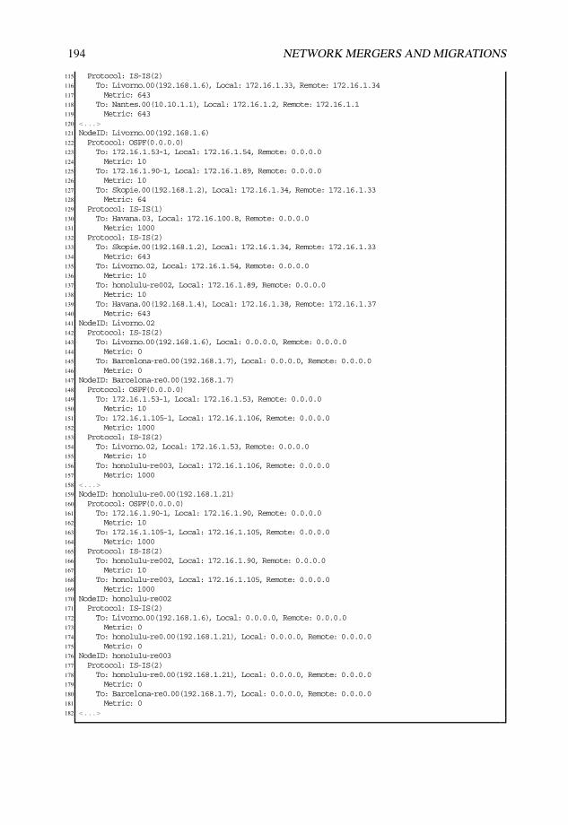
194 NETWORK MERGERS AND MIGRATIONS
115 Protocol: IS-IS(2)116 To: Livorno.00(192.168.1.6), Local: 172.16.1.33, Remote: 172.16.1.34117 Metric: 643118 To: Nantes.00(10.10.1.1), Local: 172.16.1.2, Remote: 172.16.1.1119 Metric: 643120 <...>121 NodeID: Livorno.00(192.168.1.6)122 Protocol: OSPF(0.0.0.0)123 To: 172.16.1.53-1, Local: 172.16.1.54, Remote: 0.0.0.0124 Metric: 10125 To: 172.16.1.90-1, Local: 172.16.1.89, Remote: 0.0.0.0126 Metric: 10127 To: Skopie.00(192.168.1.2), Local: 172.16.1.34, Remote: 172.16.1.33128 Metric: 64129 Protocol: IS-IS(1)130 To: Havana.03, Local: 172.16.100.8, Remote: 0.0.0.0131 Metric: 1000132 Protocol: IS-IS(2)133 To: Skopie.00(192.168.1.2), Local: 172.16.1.34, Remote: 172.16.1.33134 Metric: 643135 To: Livorno.02, Local: 172.16.1.54, Remote: 0.0.0.0136 Metric: 10137 To: honolulu-re002, Local: 172.16.1.89, Remote: 0.0.0.0138 Metric: 10139 To: Havana.00(192.168.1.4), Local: 172.16.1.38, Remote: 172.16.1.37140 Metric: 643141 NodeID: Livorno.02142 Protocol: IS-IS(2)143 To: Livorno.00(192.168.1.6), Local: 0.0.0.0, Remote: 0.0.0.0144 Metric: 0145 To: Barcelona-re0.00(192.168.1.7), Local: 0.0.0.0, Remote: 0.0.0.0146 Metric: 0147 NodeID: Barcelona-re0.00(192.168.1.7)148 Protocol: OSPF(0.0.0.0)149 To: 172.16.1.53-1, Local: 172.16.1.53, Remote: 0.0.0.0150 Metric: 10151 To: 172.16.1.105-1, Local: 172.16.1.106, Remote: 0.0.0.0152 Metric: 1000153 Protocol: IS-IS(2)154 To: Livorno.02, Local: 172.16.1.53, Remote: 0.0.0.0155 Metric: 10156 To: honolulu-re003, Local: 172.16.1.106, Remote: 0.0.0.0157 Metric: 1000158 <...>159 NodeID: honolulu-re0.00(192.168.1.21)160 Protocol: OSPF(0.0.0.0)161 To: 172.16.1.90-1, Local: 172.16.1.90, Remote: 0.0.0.0162 Metric: 10163 To: 172.16.1.105-1, Local: 172.16.1.105, Remote: 0.0.0.0164 Metric: 1000165 Protocol: IS-IS(2)166 To: honolulu-re002, Local: 172.16.1.90, Remote: 0.0.0.0167 Metric: 10168 To: honolulu-re003, Local: 172.16.1.105, Remote: 0.0.0.0169 Metric: 1000170 NodeID: honolulu-re002171 Protocol: IS-IS(2)172 To: Livorno.00(192.168.1.6), Local: 0.0.0.0, Remote: 0.0.0.0173 Metric: 0174 To: honolulu-re0.00(192.168.1.21), Local: 0.0.0.0, Remote: 0.0.0.0175 Metric: 0176 NodeID: honolulu-re003177 Protocol: IS-IS(2)178 To: honolulu-re0.00(192.168.1.21), Local: 0.0.0.0, Remote: 0.0.0.0179 Metric: 0180 To: Barcelona-re0.00(192.168.1.7), Local: 0.0.0.0, Remote: 0.0.0.0181 Metric: 0182 <...>

LINK-STATE IGP MIGRATIONS 195
As for domain “Monsoon”, router Basel and router Torino are selected as illustrativeexamples of purely internal systems, which are still unaware of the upcoming IS–ISdeployment, and a border system between both domains.
Listing 2.115 shows test results and inspections at an internal router in the OSPFv2 stubbyNSSA, excluding forwarding test results. Note the following about the output:
• Each loopback address from each participating device is represented by a Type 7 NSSAAS External LSA per ASBR, together with the externally injected route in domain“Cyclone” (starting from Line 11).
• “Gale Internet” legitimate public addresses from ABRs are visible via Type 7 NSSAAS External LSAs and not as stub networks from their Type 1 Router LSAs (startingfrom Line 11).
• Although the topology is symmetric, with two ABRs and two internal routers, routerNantes is metrically closer to the backbone than router Torino, because router Bilbaohas a GigabitEthernet link to router Nantes and an ATM OC-3 link to router Torino.This backbone topology and correct metric propagation across protocol redistributionleads the link between router Basel and router Inverness to be the preferred egress andingress traffic point for router Basel (Line 27).
Listing 2.115: Initial domain integration tests at Basel
1 user@Basel> show ospf database2
3 OSPF database, Area 0.0.0.34 Type ID Adv Rtr Seq Age Opt Cksum Len5 Router 10.10.1.1 10.10.1.1 0x80000005 394 0x20 0xe938 486 Router 10.10.1.3 10.10.1.3 0x80000004 354 0x20 0x3196 487 Router 10.10.1.9 10.10.1.9 0x80000006 507 0x20 0x4523 968 Router *10.10.1.10 10.10.1.10 0x80000004 521 0x20 0x42cb 969 Summary 0.0.0.0 10.10.1.1 0x80000003 587 0x20 0x50cc 28
10 Summary 0.0.0.0 10.10.1.3 0x80000003 2065 0x20 0x44d6 2811 NSSA 192.168.1.1 10.10.1.1 0x80000005 490 0x20 0x8b3d 3612 NSSA 192.168.1.1 10.10.1.3 0x80000002 1584 0x20 0xcb5d 3613 NSSA 192.168.1.2 10.10.1.1 0x80000003 781 0x20 0xcb5d 3614 NSSA 192.168.1.2 10.10.1.3 0x80000003 741 0x20 0x581 3615 NSSA 192.168.1.3 10.10.1.1 0x80000002 1602 0x20 0xc365 3616 NSSA 192.168.1.3 10.10.1.3 0x80000003 547 0x20 0x6f57 3617 <...>18 NSSA 192.168.10.0 10.10.1.1 0x80000003 1473 0x20 0x157d 3619 NSSA 192.168.10.0 10.10.1.3 0x80000003 1472 0x20 0x4fa0 3620
21 user@Basel> show route protocol ospf table inet.022
23 inet.0: 31 destinations, 33 routes (31 active, 0 holddown, 0 hidden)24 + = Active Route, - = Last Active, * = Both25
26 0.0.0.0/0 *[OSPF/10] 00:58:43, metric 17027 > via at-0/0/0.100128 10.10.1.9/32 *[OSPF/10] 00:59:16, metric 64329 > via at-0/1/0.100130 10.10.1.64/30 *[OSPF/10] 00:59:16, metric 128631 > via at-0/1/0.100132 10.10.1.72/30 [OSPF/10] 00:59:35, metric 64333 > via at-0/1/0.100134 10.10.1.80/30 [OSPF/10] 00:59:35, metric 16035 > via at-0/0/0.100136 192.168.1.1/32 *[OSPF/150] 00:58:33, metric 0, tag 10037 > via at-0/1/0.1001

196 NETWORK MERGERS AND MIGRATIONS
38 192.168.1.2/32 *[OSPF/150] 00:54:01, metric 160, tag 10039 > via at-0/1/0.100140 192.168.1.3/32 *[OSPF/150] 00:58:48, metric 0, tag 10041 > via at-0/0/0.100142 192.168.1.4/32 *[OSPF/150] 00:55:48, metric 743, tag 10043 > via at-0/1/0.100144 192.168.1.5/32 *[OSPF/150] 00:01:28, metric 1743, tag 10045 > via at-0/1/0.100146 192.168.1.6/32 *[OSPF/150] 00:24:38, metric 803, tag 10047 > via at-0/1/0.100148 192.168.1.7/32 *[OSPF/150] 00:24:37, metric 813, tag 10049 > via at-0/1/0.100150 192.168.1.8/32 *[OSPF/150] 00:57:05, metric 100, tag 10051 > via at-0/1/0.100152 192.168.1.9/32 *[OSPF/10] 00:59:16, metric 64353 > via at-0/1/0.100154 192.168.1.20/32 *[OSPF/150] 00:57:05, metric 743, tag 10055 > via at-0/1/0.100156 192.168.1.21/32 *[OSPF/150] 00:24:38, metric 813, tag 10057 > via at-0/1/0.100158 192.168.10.0/24 *[OSPF/150] 00:24:37, metric 813, tag 10059 > via at-0/1/0.100160 224.0.0.5/32 *[OSPF/10] 00:59:40, metric 161 MultiRecv
Listing 2.116 shows results from router Torino’s perspective, again excluding forwardingchecks. Some aspects to highlight:
• Each loopback address from each participating device is represented by a Type 7NSSA AS External LSA and a Type 5 AS External LSA per ASBR, together withthe externally injected route in domain “Cyclone” (starting from Line 51 for Type 5and Line 40 for Type 7 LSAs).
• “Gale Internet” legitimate public addresses from internal systems from domain“Monsoon” are visible via stub networks at their Type 1 Router LSAs and via Type3 Summary LSAs (starting from Line 17).
• Despite closer distance to the parallel ABR router Nantes, intra-area routes are alwayspreferred inside NSSA 0.0.0.3.
Listing 2.116: Initial domain integration tests at Torino
1 user@Torino> show isis adjacency2 Interface System L State Hold (secs) SNPA3 at-0/0/1.0 Bilbao-re0 2 Up 184 so-0/1/0.0 Nantes 2 Up 225
6 user@Torino> show ospf neighbor7 Address Interface State ID Pri Dead8 10.10.1.98 so-0/1/0.0 Full 10.10.1.1 128 329 10.10.1.82 at-1/2/0.1001 Full 10.10.1.10 128 33
10
11 user@Torino> show ospf database12
13 OSPF database, Area 0.0.0.014 Type ID Adv Rtr Seq Age Opt Cksum Len15 Router 10.10.1.1 10.10.1.1 0x80000005 2272 0x22 0x8701 6016 Router *10.10.1.3 10.10.1.3 0x80000007 2238 0x22 0x3152 6017 Summary 10.10.1.9 10.10.1.1 0x80000004 82 0x22 0xa0df 2818 Summary *10.10.1.9 10.10.1.3 0x80000004 138 0x22 0xd904 2819 Summary 10.10.1.10 10.10.1.1 0x80000003 2748 0x22 0xcc2e 2820 Summary *10.10.1.10 10.10.1.3 0x80000004 48 0x22 0x9bc6 28

LINK-STATE IGP MIGRATIONS 197
21 Summary 10.10.1.64 10.10.1.1 0x80000004 173 0x22 0x66e5 2822 Summary *10.10.1.64 10.10.1.3 0x80000004 2331 0x22 0xd44f 2823 Summary 10.10.1.72 10.10.1.1 0x80000003 2651 0x22 0x4c73 2824 Summary *10.10.1.72 10.10.1.3 0x80000003 2708 0x22 0x5151 2825 Summary 10.10.1.80 10.10.1.1 0x80000003 2554 0x22 0x42d4 2826 Summary *10.10.1.80 10.10.1.3 0x80000004 320 0x22 0xca54 2827 Summary 192.168.1.9 10.10.1.1 0x80000003 2457 0x22 0xeb40 2828 Summary *192.168.1.9 10.10.1.3 0x80000003 2611 0x22 0x2564 2829 Summary 192.168.1.10 10.10.1.1 0x80000003 2364 0x22 0x168f 2830 Summary *192.168.1.10 10.10.1.3 0x80000003 2518 0x22 0xe627 2831
32 OSPF database, Area 0.0.0.333 Type ID Adv Rtr Seq Age Opt Cksum Len34 Router 10.10.1.1 10.10.1.1 0x80000006 266 0x20 0xe739 4835 Router *10.10.1.3 10.10.1.3 0x80000005 229 0x20 0x2f97 4836 Router 10.10.1.9 10.10.1.9 0x80000007 153 0x20 0x4324 9637 Router 10.10.1.10 10.10.1.10 0x80000005 167 0x20 0x40cc 9638 Summary 0.0.0.0 10.10.1.1 0x80000004 448 0x20 0x4ecd 2839 Summary *0.0.0.0 10.10.1.3 0x80000004 2424 0x20 0x42d7 2840 NSSA 192.168.1.1 10.10.1.1 0x80000006 357 0x20 0x893e 3641 NSSA *192.168.1.1 10.10.1.3 0x80000003 2053 0x20 0xc95e 3642 NSSA 192.168.1.2 10.10.1.1 0x80000004 629 0x20 0xc95e 3643 NSSA *192.168.1.2 10.10.1.3 0x80000004 593 0x20 0x382 3644 NSSA 192.168.1.3 10.10.1.1 0x80000003 2089 0x20 0xc166 3645 NSSA *192.168.1.3 10.10.1.3 0x80000004 411 0x20 0x6d58 3646 <...>47 NSSA 192.168.10.0 10.10.1.1 0x80000004 1265 0x20 0x137e 3648 NSSA *192.168.10.0 10.10.1.3 0x80000004 1320 0x20 0x4da1 3649 OSPF AS SCOPE link state database # AS-external LSAs for all external legitimate loopback
addresses50 Type ID Adv Rtr Seq Age Opt Cksum Len51 Extern 192.168.1.1 10.10.1.1 0x80000004 537 0x22 0x8b3e 3652 Extern *192.168.1.1 10.10.1.3 0x80000003 2146 0x22 0xc760 3653 Extern 192.168.1.2 10.10.1.1 0x80000004 718 0x22 0xc760 3654 Extern *192.168.1.2 10.10.1.3 0x80000004 684 0x22 0x184 3655 Extern 192.168.1.3 10.10.1.1 0x80000003 2179 0x22 0xbf68 3656 Extern *192.168.1.3 10.10.1.3 0x80000004 502 0x22 0x6b5a 3657 <...>58 Extern 192.168.10.0 10.10.1.1 0x80000004 1354 0x22 0x1180 3659 Extern *192.168.10.0 10.10.1.3 0x80000004 1411 0x22 0x4ba3 3660
61 user@Torino> show isis database62 IS-IS level 1 link-state database:63 LSP ID Sequence Checksum Lifetime Attributes64 Torino.00-00 0xa 0x311b 606 L1 L2 Attached65 1 LSPs66
67 IS-IS level 2 link-state database: # Full visibility on all domain systems running IS-IS68 LSP ID Sequence Checksum Lifetime Attributes69 Nantes.00-00 0xf 0x811d 781 L1 L270 Nantes.02-00 0x8 0x9a45 781 L1 L271 Skopie.00-00 0xc 0x3e56 965 L1 L272 Torino.00-00 0xb 0xc1f0 744 L1 L273 Havana.00-00 0x12 0xcc65 996 L1 L274 Livorno.00-00 0x14 0x8d4f 1002 L1 L275 Livorno.02-00 0x6 0xe232 1002 L1 L276 Barcelona-re0.00-00 0xc 0xdf75 789 L1 L277 Bilbao-re0.00-00 0x10 0x5e6f 774 L1 L278 honolulu-re0.00-00 0xb 0xa849 850 L1 L279 honolulu-re0.02-00 0x8 0x23af 840 L1 L280 honolulu-re0.03-00 0x6 0x4d43 1086 L1 L281 12 LSPs82
83 user@Torino> show isis database detail84 IS-IS level 1 link-state database:85
86 Torino.00-00 Sequence: 0xa, Checksum: 0x311b, Lifetime: 604 secs87 IP prefix: 192.168.1.9/32 Metric: 803 Internal Up88 IP prefix: 192.168.1.10/32 Metric: 160 Internal Up

198 NETWORK MERGERS AND MIGRATIONS
89
90 IS-IS level 2 link-state database:91
92 Nantes.00-00 Sequence: 0xf, Checksum: 0x811d, Lifetime: 778 secs93 IS neighbor: Nantes.02 Metric: 10094 IS neighbor: Skopie.00 Metric: 16095 IS neighbor: Torino.00 Metric: 16096 IP prefix: 10.10.1.96/30 Metric: 160 Internal Up97 IP prefix: 172.16.1.0/30 Metric: 160 Internal Up98 IP prefix: 172.16.1.4/30 Metric: 100 Internal Up99 IP prefix: 192.168.1.1/32 Metric: 0 Internal Up
100 IP prefix: 192.168.1.9/32 Metric: 643 Internal Up # Inverness’ loopback101 IP prefix: 192.168.1.10/32 Metric: 1286 Internal Up # Basel’s loopback102
103 Nantes.02-00 Sequence: 0x8, Checksum: 0x9a45, Lifetime: 778 secs104 IS neighbor: Nantes.00 Metric: 0105 IS neighbor: Bilbao-re0.00 Metric: 0106 <...>107 Torino.00-00 Sequence: 0xb, Checksum: 0xc1f0, Lifetime: 741 secs108 IS neighbor: Nantes.00 Metric: 160109 IS neighbor: Bilbao-re0.00 Metric: 643110 IP prefix: 10.10.1.96/30 Metric: 160 Internal Up111 IP prefix: 172.16.1.100/30 Metric: 643 Internal Up112 IP prefix: 192.168.1.3/32 Metric: 0 Internal Up113 IP prefix: 192.168.1.9/32 Metric: 803 Internal Up # Inverness’ loopback114 IP prefix: 192.168.1.10/32 Metric: 160 Internal Up # Basel’s loopback115 <...>116 user@Torino> show route protocol ospf table inet.0117
118 inet.0: 50 destinations, 65 routes (50 active, 0 holddown, 0 hidden)119 + = Active Route, - = Last Active, * = Both120
121 10.10.1.1/32 *[OSPF/10] 01:42:52, metric 160122 > via so-0/1/0.0123 10.10.1.9/32 *[OSPF/10] 01:43:00, metric 803124 > via at-1/2/0.1001125 <...>126 192.168.1.1/32 [OSPF/150] 01:42:52, metric 0, tag 100127 > via so-0/1/0.0128 192.168.1.2/32 [OSPF/150] 01:38:15, metric 160, tag 100129 > via so-0/1/0.0130 192.168.1.3/32 [OSPF/150] 01:41:40, metric 160, tag 100131 > via so-0/1/0.0132 192.168.1.4/32 [OSPF/150] 01:40:07, metric 743, tag 100133 > via so-0/1/0.0134 192.168.1.5/32 [OSPF/150] 00:45:42, metric 1743, tag 100135 > via so-0/1/0.0136 192.168.1.6/32 [OSPF/150] 01:08:52, metric 803, tag 100137 > via so-0/1/0.0138 192.168.1.7/32 [OSPF/150] 01:08:52, metric 813, tag 100139 > via so-0/1/0.0140 192.168.1.8/32 [OSPF/150] 01:41:21, metric 100, tag 100141 > via so-0/1/0.0142 192.168.1.9/32 *[OSPF/10] 01:43:00, metric 803143 > via at-1/2/0.1001144 192.168.1.10/32 *[OSPF/10] 01:43:00, metric 160145 > via at-1/2/0.1001146 192.168.1.20/32 [OSPF/150] 01:41:21, metric 743, tag 100147 > via so-0/1/0.0148 192.168.1.21/32 [OSPF/150] 01:08:52, metric 813, tag 100149 > via so-0/1/0.0150 192.168.10.0/24 [OSPF/150] 01:08:52, metric 813, tag 100151 > via so-0/1/0.0152 224.0.0.5/32 *[OSPF/10] 04:15:08, metric 1153 MultiRecv154
155 user@Torino> show route protocol isis table inet.0156
157 inet.0: 50 destinations, 65 routes (50 active, 0 holddown, 0 hidden)

LINK-STATE IGP MIGRATIONS 199
158 + = Active Route, - = Last Active, * = Both159
160 172.16.1.0/30 *[IS-IS/18] 01:41:48, metric 320161 > to 10.10.1.98 via so-0/1/0.0162 172.16.1.4/30 *[IS-IS/18] 01:41:48, metric 260163 > to 10.10.1.98 via so-0/1/0.0164 <...>165 192.168.1.1/32 *[IS-IS/18] 01:41:48, metric 160166 > to 10.10.1.98 via so-0/1/0.0167 192.168.1.2/32 *[IS-IS/18] 01:38:23, metric 320168 > to 10.10.1.98 via so-0/1/0.0169 192.168.1.4/32 *[IS-IS/18] 01:40:15, metric 903170 > to 10.10.1.98 via so-0/1/0.0171 192.168.1.5/32 *[IS-IS/18] 00:45:50, metric 1903172 > to 10.10.1.98 via so-0/1/0.0173 192.168.1.6/32 *[IS-IS/18] 01:09:00, metric 963174 > to 10.10.1.98 via so-0/1/0.0175 192.168.1.7/32 *[IS-IS/18] 01:09:00, metric 973176 > to 10.10.1.98 via so-0/1/0.0177 192.168.1.8/32 *[IS-IS/18] 01:41:34, metric 260178 > to 10.10.1.98 via so-0/1/0.0179 192.168.1.9/32 [IS-IS/18] 00:02:46, metric 803, tag 200, tag2 3180 > to 10.10.1.98 via so-0/1/0.0181 192.168.1.20/32 *[IS-IS/18] 01:41:34, metric 903182 > to 10.10.1.98 via so-0/1/0.0183 192.168.1.21/32 *[IS-IS/18] 01:09:00, metric 973184 > to 10.10.1.98 via so-0/1/0.0185 192.168.10.0/24 *[IS-IS/18] 01:09:00, metric 973186 > to 10.10.1.98 via so-0/1/0.0
Listing 2.117 describes router Havana’s view, except for forwarding test results. It isworth emphasizing some topics as follows:
• Router Havana is not setting the ATTached bit on L1 LSPs, because all existing areasare visible through Level 1 (Line 12);
• The Up/Down bit is properly marked inside respective L1 LSP TLVs for routinginformation leaked from Level 2 to Level 1 to avoid Level 2 reinjection (starting fromLine 47);
• Domain “Monsoon” injected prefixes are easily identified via route Tag 200 (Lines 118and 120).
Listing 2.117: Initial domain integration tests at Havana
1 user@Havana> show isis adjacency2 Interface System L State Hold (secs) SNPA3 at-1/2/0.1001 Bilbao-re0 3 Up 26 # L1 and L2 adjacency over same link4 fe-0/3/0.0 Lille 1 Up 24 0:14:f6:81:48:5d5 fe-0/3/0.0 Livorno 1 Up 20 0:14:f6:85:40:5d6 ge-1/1/0.0 male-re0 1 Up 25 0:19:e2:2b:38:fa7 so-1/0/0.0 Livorno 2 Up 248
9 user@Havana> show isis database10 IS-IS level 1 link-state database:11 LSP ID Sequence Checksum Lifetime Attributes12 Havana.00-00 0x14 0x9177 1030 L1 L2 # No ATTached bit13 Havana.02-00 0x8 0x1fa3 838 L1 L214 Havana.03-00 0x8 0x962e 838 L1 L215 Lille.00-00 0x6 0x4171 633 L116 Livorno.00-00 0x16 0xa8d8 676 L1 L217 Bilbao-re0.00-00 0x15 0x5e1b 988 L1 L218 male-re0.00-00 0xb 0x6c38 1072 L119 7 LSPs20

200 NETWORK MERGERS AND MIGRATIONS
21 IS-IS level 2 link-state database:22 LSP ID Sequence Checksum Lifetime Attributes23 Nantes.00-00 0xf 0x811d 617 L1 L224 Nantes.02-00 0x8 0x9a45 617 L1 L225 Skopie.00-00 0xc 0x3e56 802 L1 L226 Torino.00-00 0xb 0xc1f0 577 L1 L227 Havana.00-00 0x12 0xcc65 838 L1 L228 Livorno.00-00 0x14 0x8d4f 843 L1 L229 Livorno.02-00 0x6 0xe232 843 L1 L230 Barcelona-re0.00-00 0xc 0xdf75 631 L1 L231 Bilbao-re0.00-00 0x10 0x5e6f 611 L1 L232 honolulu-re0.00-00 0xb 0xa849 691 L1 L233 honolulu-re002-00 0x8 0x23af 682 L1 L234 honolulu-re003-00 0x6 0x4d43 928 L1 L235 12 LSPs36
37 user@Havana> show isis database detail38 IS-IS level 1 link-state database:39
40 Havana.00-00 Sequence: 0x12, Checksum: 0x1a06, Lifetime: 388 secs41 IS neighbor: Havana.02 Metric: 100042 IS neighbor: Havana.03 Metric: 10043 IS neighbor: Bilbao-re0.00 Metric: 64344 IP prefix: 172.16.1.40/30 Metric: 643 Internal Up45 IP prefix: 172.16.1.84/30 Metric: 100 Internal Up46 IP prefix: 172.16.100.0/24 Metric: 1000 Internal Up47 IP prefix: 192.168.1.1/32 Metric: 743 Internal Down # From IS-IS Level 248 IP prefix: 192.168.1.3/32 Metric: 903 Internal Down # From IS-IS Level 249 IP prefix: 192.168.1.4/32 Metric: 0 Internal Up50 IP prefix: 192.168.1.9/32 Metric: 1386 Internal Down # From IS-IS Level 251 IP prefix: 192.168.1.10/32 Metric: 1063 Internal Down # From IS-IS Level 252
53 Havana.02-00 Sequence: 0x8, Checksum: 0x1fa3, Lifetime: 835 secs54 IS neighbor: Havana.00 Metric: 055 IS neighbor: male-re0.00 Metric: 056
57 Havana.03-00 Sequence: 0x8, Checksum: 0x962e, Lifetime: 835 secs58 IS neighbor: Havana.00 Metric: 059 IS neighbor: Lille.00 Metric: 060 IS neighbor: Livorno.00 Metric: 061
62 Lille.00-00 Sequence: 0x6, Checksum: 0x4171, Lifetime: 631 secs63 IS neighbor: Havana.03 Metric: 100064 IP prefix: 172.16.100.0/24 Metric: 1000 Internal Up65 IP prefix: 192.168.1.5/32 Metric: 0 Internal Up66
67 Livorno.00-00 Sequence: 0x13, Checksum: 0x32fe, Lifetime: 585 secs68 IS neighbor: Havana.02 Metric: 100069 IP prefix: 172.16.100.0/24 Metric: 1000 Internal Up70 IP prefix: 192.168.1.1/32 Metric: 1286 Internal Down # From IS-IS Level 271 IP prefix: 192.168.1.2/32 Metric: 64 Internal Up # From OSPFv272 IP prefix: 192.168.1.3/32 Metric: 1446 Internal Down # From IS-IS Level 273 IP prefix: 192.168.1.6/32 Metric: 0 Internal Up74 IP prefix: 192.168.1.7/32 Metric: 10 Internal Up # From OSPFv275 IP prefix: 192.168.1.9/32 Metric: 1929 Internal Down # From IS-IS Level 276 IP prefix: 192.168.1.10/32 Metric: 1606 Internal Down # From IS-IS Level 277 IP prefix: 192.168.1.21/32 Metric: 10 Internal Up # From OSPFv278 IP prefix: 192.168.10.0/24 Metric: 0 Internal Up79
80 Bilbao-re0.00-00 Sequence: 0x19, Checksum: 0xf990, Lifetime: 548 secs81 IS neighbor: Havana.00 Metric: 64382 IS neighbor: male-re0.00 Metric: 64383 IP prefix: 172.16.1.40/30 Metric: 643 Internal Up84 IP prefix: 172.16.1.76/30 Metric: 643 Internal Up85 IP prefix: 192.168.1.1/32 Metric: 100 Internal Down # From IS-IS Level 286 IP prefix: 192.168.1.3/32 Metric: 260 Internal Down # From IS-IS Level 287 IP prefix: 192.168.1.8/32 Metric: 0 Internal Up88 IP prefix: 192.168.1.9/32 Metric: 743 Internal Down # From IS-IS Level 289 IP prefix: 192.168.1.10/32 Metric: 420 Internal Down # From IS-IS Level 2

LINK-STATE IGP MIGRATIONS 201
90
91 <...>92
93 IS-IS level 2 link-state database:94 <...>95
96 user@Havana> show route protocol isis table inet.097
98 inet.0: 46 destinations, 46 routes (46 active, 0 holddown, 0 hidden)99 + = Active Route, - = Last Active, * = Both
100
101 <...>102 172.16.1.104/30 *[IS-IS/18] 01:11:35, metric 1653103 > to 172.16.1.38 via so-1/0/0.0104 192.168.1.1/32 *[IS-IS/18] 01:42:40, metric 743105 > to 172.16.1.42 via at-1/2/0.1001106 192.168.1.2/32 *[IS-IS/15] 01:14:53, metric 1064, tag 300 # From domain Cyclone107 > to 172.16.100.8 via fe-0/3/0.0108 192.168.1.3/32 *[IS-IS/18] 01:42:40, metric 903109 > to 172.16.1.42 via at-1/2/0.1001110 192.168.1.5/32 *[IS-IS/15] 00:48:24, metric 1000111 > to 172.16.100.5 via fe-0/3/0.0112 192.168.1.6/32 *[IS-IS/15] 01:12:03, metric 1000113 > to 172.16.100.8 via fe-0/3/0.0114 192.168.1.7/32 *[IS-IS/15] 01:14:53, metric 1010, tag 300 # From domain Cyclone115 > to 172.16.100.8 via fe-0/3/0.0116 192.168.1.8/32 *[IS-IS/15] 01:42:50, metric 643117 > to 172.16.1.42 via at-1/2/0.1001118 192.168.1.9/32 *[IS-IS/18] 01:42:40, metric 1386, tag 200, tag2 3 # From domain Monsoon119 > to 172.16.1.42 via at-1/2/0.1001120 192.168.1.10/32 *[IS-IS/18] 01:42:40, metric 1063, tag 200, tag2 3 # From domain Monsoon121 > to 172.16.1.42 via at-1/2/0.1001122 192.168.1.20/32 *[IS-IS/15] 01:43:21, metric 100123 > to 172.16.1.85 via ge-1/1/0.0124 192.168.1.21/32 *[IS-IS/15] 01:14:53, metric 1010, tag 300 # From domain Cyclone125 > to 172.16.100.8 via fe-0/3/0.0126 192.168.10.0/24 *[IS-IS/15] 01:14:53, metric 1000, tag 300 # From domain Cyclone127 > to 172.16.100.8 via fe-0/3/0.0
Finally, Listing 2.118 shows the domain view at router Lille (forwarding testing notincluded). Some points worth mentioning:
• Neither router Havana nor router Livorno nor router Bilbao are setting the ATTachedbit on L1 LSPs, as all existing areas are visible through Level 1 (starting from Line 9).
• The Up/Down bit is properly marked inside respective L1 LSP TLVs for routinginformation leaked from Level 2 to Level 1 to avoid Level 2 reinjection (starting fromLine 31).
• Router Livorno leaks also routes actively present in its routing table via OSPFv2 toLevel 1 and they do not have the Up/Down bit set (starting from Line 68).
Listing 2.118: Initial domain integration tests at Lille
1 user@Lille> show isis adjacency2 Interface System L State Hold (secs) SNPA3 fe-0/3/0.0 Havana 1 Up 8 0:90:69:b4:bc:5d4 fe-0/3/0.0 Livorno 1 Up 24 0:14:f6:85:40:5d5
6 user@Lille> show isis database7 IS-IS level 1 link-state database:8 LSP ID Sequence Checksum Lifetime Attributes9 Havana.00-00 0x14 0x9177 805 L1 L2 # No ATTached bit set

202 NETWORK MERGERS AND MIGRATIONS
10 Havana.02-00 0x8 0x1fa3 612 L1 L211 Havana.03-00 0x8 0x962e 613 L1 L212 Lille.00-00 0x6 0x4171 412 L113 Livorno.00-00 0x16 0xa8d8 452 L1 L2 # No ATTached bit set14 Bilbao-re0.00-00 0x15 0x5e1b 763 L1 L2 # No ATTached bit set15 male-re0.00-00 0xb 0x6c38 847 L116 7 LSPs17
18 IS-IS level 2 link-state database:19 0 LSPs20
21 user@Lille> show isis database detail22 IS-IS level 1 link-state database:23
24 Havana.00-00 Sequence: 0x12, Checksum: 0x1a06, Lifetime: 388 secs25 IS neighbor: Havana.02 Metric: 100026 IS neighbor: Havana.03 Metric: 10027 IS neighbor: Bilbao-re0.00 Metric: 64328 IP prefix: 172.16.1.40/30 Metric: 643 Internal Up29 IP prefix: 172.16.1.84/30 Metric: 100 Internal Up30 IP prefix: 172.16.100.0/24 Metric: 1000 Internal Up31 IP prefix: 192.168.1.1/32 Metric: 743 Internal Down # From IS-IS Level 232 IP prefix: 192.168.1.3/32 Metric: 903 Internal Down # From IS-IS Level 233 IP prefix: 192.168.1.4/32 Metric: 0 Internal Up34 IP prefix: 192.168.1.9/32 Metric: 1386 Internal Down # From IS-IS Level 235 IP prefix: 192.168.1.10/32 Metric: 1063 Internal Down # From IS-IS Level 236 <...>37 Livorno.00-00 Sequence: 0x13, Checksum: 0x32fe, Lifetime: 585 secs38 IS neighbor: Havana.02 Metric: 100039 IP prefix: 172.16.100.0/24 Metric: 1000 Internal Up40 IP prefix: 192.168.1.1/32 Metric: 1286 Internal Down # From IS-IS Level 241 IP prefix: 192.168.1.2/32 Metric: 64 Internal Up # From OSPFv242 IP prefix: 192.168.1.3/32 Metric: 1446 Internal Down # From IS-IS Level 243 IP prefix: 192.168.1.6/32 Metric: 0 Internal Up44 IP prefix: 192.168.1.7/32 Metric: 10 Internal Up # From OSPFv245 IP prefix: 192.168.1.9/32 Metric: 1929 Internal Down # From IS-IS Level 246 IP prefix: 192.168.1.10/32 Metric: 1606 Internal Down # From IS-IS Level 247 IP prefix: 192.168.1.21/32 Metric: 10 Internal Up # From OSPFv248 IP prefix: 192.168.10.0/24 Metric: 0 Internal Up49
50 Bilbao-re0.00-00 Sequence: 0x19, Checksum: 0xf990, Lifetime: 548 secs51 IS neighbor: Havana.00 Metric: 64352 IS neighbor: male-re0.00 Metric: 64353 IP prefix: 172.16.1.40/30 Metric: 643 Internal Up54 IP prefix: 172.16.1.76/30 Metric: 643 Internal Up55 IP prefix: 192.168.1.1/32 Metric: 100 Internal Down # From IS-IS Level 256 IP prefix: 192.168.1.3/32 Metric: 260 Internal Down # From IS-IS Level 257 IP prefix: 192.168.1.8/32 Metric: 0 Internal Up58 IP prefix: 192.168.1.9/32 Metric: 743 Internal Down # From IS-IS Level 259 IP prefix: 192.168.1.10/32 Metric: 420 Internal Down # From IS-IS Level 260 <...>61
62 user@Lille> show route protocol isis table inet.063
64 inet.0: 35 destinations, 35 routes (35 active, 0 holddown, 0 hidden)65 + = Active Route, - = Last Active, * = Both66
67 <...>68 192.168.1.1/32 *[IS-IS/18] 00:51:55, metric 1743, tag 300 # Leaked due to policy69 > to 172.16.100.1 via fe-0/3/0.070 192.168.1.2/32 *[IS-IS/18] 00:51:55, metric 1903, tag 300 # Leaked due to policy71 > to 172.16.100.1 via fe-0/3/0.072 192.168.1.3/32 *[IS-IS/18] 00:51:55, metric 1903, tag 300 # Leaked due to policy73 > to 172.16.100.1 via fe-0/3/0.074 192.168.1.4/32 *[IS-IS/15] 00:51:55, metric 100075 > to 172.16.100.1 via fe-0/3/0.076 192.168.1.6/32 *[IS-IS/15] 00:51:39, metric 100077 > to 172.16.100.8 via fe-0/3/0.078 192.168.1.7/32 *[IS-IS/18] 00:51:55, metric 1653, tag 300 # Leaked due to policy

LINK-STATE IGP MIGRATIONS 203
79 > to 172.16.100.1 via fe-0/3/0.080 192.168.1.8/32 *[IS-IS/15] 00:51:54, metric 164381 > to 172.16.100.1 via fe-0/3/0.082 192.168.1.9/32 *[IS-IS/18] 00:51:55, metric 2386, tag 300, tag2 3 # Leaked due to policy83 > to 172.16.100.1 via fe-0/3/0.084 192.168.1.10/32 *[IS-IS/18] 00:51:55, metric 2063, tag 300, tag2 3 # Leaked due to policy85 > to 172.16.100.1 via fe-0/3/0.086 192.168.1.20/32 *[IS-IS/15] 00:51:54, metric 110087 > to 172.16.100.1 via fe-0/3/0.088 192.168.1.21/32 *[IS-IS/18] 00:51:55, metric 1653, tag 300 # Leaked due to policy89 > to 172.16.100.1 via fe-0/3/0.090 192.168.10.0/24 *[IS-IS/18] 00:51:55, metric 1653, tag 300 # Leaked due to policy91 > to 172.16.100.1 via fe-0/3/0.0
At this stage, basic connectivity to all systems is granted, and the very first milestonein our migration has been successfully achieved without modifying any previously existingforwarding paths in any domain and without any other kind of service disruption. The stateof the global setup after reaching this first milestone is summarized in Figure 2.25.
L2
L2
L2
L2
L2
L2
Male
Bilbao
Havana
Nantes
Skopie
Livorno
Barcelona
Honolulu
192.168.1.4
192.168.1.20
192.168.1.8
10.10.1.1
192.168.1.1
192.168.1.2
192.168.1.6
192.168.1.7
192.168.1.21
Torino
Lille
10.10.1.9
192.168.1.19
InvernessBasel
192.168.1.5
10.10.1.3
192.168.1.3
10.10.1.10
192.168.1.10
OSPFv2 domain
"Monsoon"
IS−IS domain
"Mistral"
Area 49.0001OSPFv2 domain
"Cyclone"
L1
L1
NOC mgmt
center
Area 49.0003
L1
Final IS−IS
domain
Area 49.0003
− Redistribute OSPFv2 to IS−IS
with route−filter 192.168.1.0/24 prefix−length /32
− Block tagged routes
− Redistribute IS−IS and direct
to OSPFv2 with route−filter
192.168.1.0/24 prefix−length /32
− Tag routes with admin value
− OSPFv2 and IS−IS as
"ships in the night" with
default preferences
− Adapt TED credibility
− Avoid authentication checks
for domain integration
− Add Area for L1 adjacency
L1
NSSA no−summaries 0.0.0.3
Area 0.0.0.0
Area 0.0.0.0
TE extensions
Cost 1000
Figure 2.25: Stage six: domain IGP interconnect.
2.3.10 Stage seven: OSPFv2 to IS–IS Level 2 transition in domain“Cyclone”
At this stage, IS–IS should transition to become the most preferred and TED-credible proto-col. Because of the previous configuration of traffic-engineering credibility-protocol-preference, changing IS–IS Level 2 and 1 preferences in participatingsystems at this point directly affects the credibility values for the TED.

204 NETWORK MERGERS AND MIGRATIONS
Because the final objective in the migration is to dismantle OSPFv2 completely, itis necessary at some point to completely remove OSPFv2 adjacencies. Even if OSPFv2becomes unpreferred, by default, RSVP is notified when OSPFv2 adjacencies drop, so asto trigger the corresponding notification for expedited MPLS convergence.
However, in our case, connectivity is ensured by IS–IS at that point, so dropping RSVPneighbors and generating the corresponding notifications upon removal of OSPFv2 is notdesired. As previously described, the Junos OS OSPFv2 knob no-neighbor-down-notification skips that notification, with the intention fully to transition in a ships-in-the-night model from OSPFv2 to another preferred protocol. Note that this knob needs to beactivated on the corresponding links before dismantling their adjacencies so that the routeris previously aware of that operation. Activating such a configuration option in advance isentirely graceful for the system and simply acts as previous advice, while also unprotectingthe setup from RSVP reaction against legitimate IGP failures. Thus, it is recommended tokeep it active only for a transient period.
To summarize, this migration round through the systems in domain “Cyclone” shouldcover the following activities:
• protocol preference transition to automatically consider IS–IS Levels 1 and 2 as mostcredible protocols towards routing table and TED;
• activation of no-neighbor-down-notification for existing OSPFv2 adjacen-cies.
Because internal and external preferences for OSPFv2 and IS–IS Level 1 and Level 2 needto be tuned, the rationale for the preference adaption this time is to restore default values forIS–IS and to mark OSPFv2 as unpreferred, all with the same Junos OS commit. With the ideaof avoiding any other collisions with BGP or other protocols, the following values have beenselected:
• IS–IS Level 1 internal preference = 15 (default);
• IS–IS Level 2 internal preference = 18 (default);
• IS–IS Level 1 external preference = 160 (default);
• IS–IS Level 2 external preference = 165 (default);
• OSPF internal route = 167;
• OSPF AS external route = 169.
Once corresponding checks are issued in the complete domain and no OSPFv2 pathsremain active in the routing table, OSPFv2 can be safely removed from routers withoutfurther impact.
Modifying protocol preferences and adding no-neighbor-down-notificationto existing OSPFv2 adjacencies are completely graceful actions for existing IGP adjacenciesin this setup, as shown in representative Listing 2.119 for router Livorno. At the same time,OSPFv2 preferred routes are not leaked in router Livorno, by deactivating the referringleaking policy term.

LINK-STATE IGP MIGRATIONS 205
Listing 2.119: Protocol preference adaption and RSVP notification drop avoidance in Livorno
1 [edit]2 user@Livorno# set protocols ospf preference 1673 [edit]4 user@Livorno# set protocols ospf external-preference 1695 [edit]6 user@Livorno# delete protocols isis level 1 preference7 [edit]8 user@Livorno# delete protocols isis level 2 preference9 [edit protocols ospf area 0]
10 user@Livorno# set interface so-0/0/0.0 no-neighbor-down-notification11 [edit protocols ospf area 0]12 user@Livorno# set interface ge-0/2/0.0 no-neighbor-down-notification13 [edit protocols ospf area 0]14 user@Livorno# set interface ge-1/3/0.0 no-neighbor-down-notification15 [edit]16 user@Livorno# deactivate policy-options policy-statement leak-loopbacks-to-l1 term ospf17
18 user@Livorno> show route protocol ospf active-path table inet.019
20 inet.0: 41 destinations, 47 routes (40 active, 0 holddown, 1 hidden)21 + = Active Route, - = Last Active, * = Both22
23 224.0.0.5/32 *[OSPF/10] 02:39:56, metric 1 # No active routes apart from allOSPFrouters multicast24 MultiRecv25
26 user@Livorno> show route protocol isis terse table inet.027 # Fully integrated domain in IS-IS28
29 inet.0: 41 destinations, 47 routes (40 active, 0 holddown, 1 hidden)30 + = Active Route, - = Last Active, * = Both31
32 A Destination P Prf Metric 1 Metric 2 Next hop AS path33 <...>34 * 172.16.1.40/30 I 15 1643 >172.16.100.135 * 172.16.1.76/30 I 15 1743 >172.16.100.136 * 172.16.1.84/30 I 15 1100 >172.16.100.137 * 172.16.1.100/30 I 18 1929 >172.16.1.3738 * 172.16.1.104/30 I 18 1010 >172.16.1.5339 172.16.1.9040 * 192.168.1.1/32 I 18 1286 >172.16.1.3341 * 192.168.1.2/32 I 18 643 >172.16.1.3342 * 192.168.1.3/32 I 18 1446 >172.16.1.3343 * 192.168.1.4/32 I 15 1000 >172.16.100.144 * 192.168.1.5/32 I 15 1000 >172.16.100.545 * 192.168.1.7/32 I 18 10 >172.16.1.5346 * 192.168.1.8/32 I 15 1643 >172.16.100.147 * 192.168.1.9/32 I 18 1929 >172.16.1.3348 * 192.168.1.10/32 I 18 1606 >172.16.1.3349 * 192.168.1.20/32 I 15 1100 >172.16.100.150 * 192.168.1.21/32 I 18 10 >172.16.1.9051 * 192.168.10.0/24 I 18 10 >172.16.1.5352
53 user@Livorno> show isis database detail Livorno54 IS-IS level 1 link-state database:55
56 Livorno.00-00 Sequence: 0x19, Checksum: 0x93d7, Lifetime: 890 secs57 IS neighbor: Havana.02 Metric: 100058 IP prefix: 172.16.100.0/24 Metric: 1000 Internal Up59 IP prefix: 192.168.1.1/32 Metric: 1286 Internal Down60 IP prefix: 192.168.1.2/32 Metric: 643 Internal Down # Leaking from IS-IS L261 IP prefix: 192.168.1.3/32 Metric: 1446 Internal Down62 IP prefix: 192.168.1.6/32 Metric: 0 Internal Up63 IP prefix: 192.168.1.7/32 Metric: 10 Internal Down # Leaking from IS-IS L264 IP prefix: 192.168.1.9/32 Metric: 1929 Internal Down65 IP prefix: 192.168.1.10/32 Metric: 1606 Internal Down66 IP prefix: 192.168.1.21/32 Metric: 10 Internal Down # Leaking from IS-IS L267 IP prefix: 192.168.10.0/24 Metric: 10 Internal Down68

206 NETWORK MERGERS AND MIGRATIONS
69 IS-IS level 2 link-state database:70
71 Livorno.00-00 Sequence: 0x1f, Checksum: 0x23b0, Lifetime: 890 secs72 IS neighbor: Skopie.00 Metric: 64373 IS neighbor: Havana.00 Metric: 64374 IS neighbor: Livorno.02 Metric: 1075 IS neighbor: honolulu-re0.02 Metric: 1076 IP prefix: 172.16.1.32/30 Metric: 643 Internal Up77 IP prefix: 172.16.1.36/30 Metric: 643 Internal Up78 IP prefix: 172.16.1.40/30 Metric: 1643 Internal Up79 IP prefix: 172.16.1.52/30 Metric: 10 Internal Up80 IP prefix: 172.16.1.76/30 Metric: 1743 Internal Up81 IP prefix: 172.16.1.84/30 Metric: 1100 Internal Up82 IP prefix: 172.16.1.88/30 Metric: 10 Internal Up83 IP prefix: 172.16.100.0/24 Metric: 1000 Internal Up84 IP prefix: 192.168.1.4/32 Metric: 1000 Internal Up85 IP prefix: 192.168.1.6/32 Metric: 0 Internal Up86 IP prefix: 192.168.1.8/32 Metric: 1643 Internal Up87 IP prefix: 192.168.1.20/32 Metric: 1100 Internal Up88
89 Livorno.02-00 Sequence: 0xc, Checksum: 0x6bc2, Lifetime: 890 secs90 IS neighbor: Livorno.00 Metric: 091 IS neighbor: Barcelona-re0.00 Metric: 092
93 user@Livorno> show ted protocol94 Protocol name Credibility Self node95 IS-IS(1) 497 Livorno.00(192.168.1.6)96 IS-IS(2) 494 Livorno.00(192.168.1.6)97 OSPF(0) 345 Livorno.00(192.168.1.6)
Similar graceful protocol transitions take place on all other systems in this domain,although it is recommended that the existing IS–IS Level 2 be expanded simultaneously foroperational purposes.
What If... Route preference for locally injected prefixes with IS–IS Up/Down bit set
A particular corner case deserves further comments. Even though IS–IS becomes the morepreferred protocol, if the route injection via export policy is not deactivated or removed,OSPFv2 routes still remain preferred in Junos OS. Listing 2.120 illustrates the previouscase at router Livorno without deactivating injection.
Listing 2.120: Routing table and IS–IS Database status at Livorno with OSPF external routeinjection1 user@Livorno> show route protocol ospf active-path table inet.02
3 inet.0: 41 destinations, 43 routes (40 active, 0 holddown, 1 hidden)4 + = Active Route, - = Last Active, * = Both5
6 192.168.1.2/32 *[OSPF/167] 00:06:11, metric 647 > via so-0/0/0.08 192.168.1.7/32 *[OSPF/167] 00:06:11, metric 109 > to 172.16.1.53 via ge-0/2/0.0
10 192.168.1.21/32 *[OSPF/167] 00:06:11, metric 1011 > to 172.16.1.90 via ge-1/3/0.012 192.168.10.0/24 *[OSPF/169] 00:06:11, metric 0, tag 013 > to 172.16.1.53 via ge-0/2/0.014 224.0.0.5/32 *[OSPF/10] 02:19:09, metric 115 MultiRecv16
17 user@Livorno> show isis database detail Livorno level 1

LINK-STATE IGP MIGRATIONS 207
18 Livorno.00-00 Sequence: 0x16, Checksum: 0xfa4c, Lifetime: 806 secs19 IS neighbor: Havana.02 Metric: 100020 IP prefix: 172.16.100.0/24 Metric: 1000 Internal Up21 IP prefix: 192.168.1.1/32 Metric: 1286 Internal Down # Leaking retained22 IP prefix: 192.168.1.2/32 Metric: 64 Internal Up23 IP prefix: 192.168.1.3/32 Metric: 1446 Internal Down # Leaking retained24 IP prefix: 192.168.1.6/32 Metric: 0 Internal Up25 IP prefix: 192.168.1.7/32 Metric: 10 Internal Up26 IP prefix: 192.168.1.9/32 Metric: 1929 Internal Down # Leaking retained27 IP prefix: 192.168.1.10/32 Metric: 1606 Internal Down # Leaking retained28 IP prefix: 192.168.1.21/32 Metric: 10 Internal Up29 IP prefix: 192.168.10.0/24 Metric: 0 Internal Up30
31
32 user@Livorno> show route 192.168.1.2 extensive table inet.033
34 inet.0: 41 destinations, 43 routes (40 active, 0 holddown, 1 hidden)35 192.168.1.2/32 (1 entry, 1 announced)36 TSI:37 KRT in-kernel 192.168.1.2/32 -> {so-0/0/0.0}38 IS-IS level 1, LSP fragment 039 *OSPF Preference: 167 # IS-IS route does not appear, only modified OSPF preference40 Next hop type: Router, Next hop index: 56841 Next-hop reference count: 342 Next hop: via so-0/0/0.0, selected43 State: <Active Int>44 Age: 7:11 Metric: 6445 Area: 0.0.0.046 Task: OSPF47 Announcement bits (3): 0-KRT 4-LDP 5-IS-IS48 AS path: I
This situation, where the IS–IS route does not appear, is a built-in security mechanismwhen injecting routes into Level 1 without the Up/Down bit set to prevent an indirectbackdoor for a routing loop when leaking if the Up/Down bit were not set.
Once the policy term is deactivated, OSPFv2 active routes disappear and leaked prefixesare tagged with the Up/Down bit, as shown in Listing 2.121.
Listing 2.121: Routing table and IS–IS Database status at Livorno without OSPF externalroute injection
1 [edit policy-options policy-statement leak-loopbacks-to-l1]2 user@Livorno# deactivate term ospf3
4 user@Livorno> show route 192.168.1.2 extensive table inet.05
6 inet.0: 41 destinations, 47 routes (40 active, 0 holddown, 1 hidden)7 192.168.1.2/32 (2 entries, 1 announced)8 TSI:9 KRT in-kernel 192.168.1.2/32 -> {172.16.1.33}
10 IS-IS level 1, LSP fragment 011 *IS-IS Preference: 18 # IS-IS route is preferred now12 Level: 213 Next hop type: Router, Next hop index: 51814 Next-hop reference count: 1415 Next hop: 172.16.1.33 via so-0/0/0.0, selected16 State: <Active Int>17 Age: 4 Metric: 64318 Task: IS-IS19 Announcement bits (3): 0-KRT 4-LDP 5-IS-IS20 AS path: I21 OSPF Preference: 167 # OSPF route unpreferred22 Next hop type: Router, Next hop index: 56823 Next-hop reference count: 224 Next hop: via so-0/0/0.0, selected

208 NETWORK MERGERS AND MIGRATIONS
25 State: <Int>26 Inactive reason: Route Preference27 Age: 7:59 Metric: 6428 Area: 0.0.0.029 Task: OSPF30 AS path: I
Once these changes are completely deployed on all systems, after checking that noOSPFv2 routes remain as active paths in any routing table, OSPFv2 can be deleted andsystems can be considered as completely integrated in the final domain. Listing 2.122illustrates those changes in router Livorno, which has an RSVP-TE LSP full mesh towardsall systems in the previous domain “Cyclone”, that remains stable upon these modifications.
Listing 2.122: OSPFv2 final removal in Livorno
1 user@Livorno> monitor start messages2 user@Livorno> monitor start rsvp-transition3 user@Livorno> monitor start mpls-transition4
5 [edit protocols mpls]6 user@Livorno# show7 traceoptions {8 file mpls-transition;9 flag state;
10 flag error;11 }12 label-switched-path Livorno-to-Skopie {13 to 192.168.1.2;14 }15 label-switched-path Livorno-to-Barcelona {16 to 192.168.1.7;17 }18 label-switched-path Livorno-to-Honolulu {19 to 192.168.1.21;20 }21 interface fxp0.0 {22 disable;23 }24 interface so-0/0/0.0;25 interface ge-0/2/0.0;26 interface ge-1/3/0.0;27
28 [edit protocols rsvp]29 user@Livorno# show30 traceoptions {31 file rsvp-transition;32 flag error;33 flag event;34 flag pathtear;35 flag state;36 }37 interface fxp0.0 {38 disable;39 }40 interface so-0/0/0.0 {41 link-protection;42 }43 interface ge-0/2/0.0 {44 link-protection;45 }46 interface ge-1/3/0.0 {47 link-protection;48 }49

LINK-STATE IGP MIGRATIONS 209
50 [edit]51 user@Livorno# delete protocols ospf52 [edit]53 user@Livorno# commit and-quit54 *** mpls-transition ***55 Apr 6 01:09:53.834589 TED free LINK Livorno.00(192.168.1.6)->0000.0000.0000.00(172.16.1.53); Local
Node: 172.16.1.54(192.168.1.6:0) Remote Node: 0.0.0.0(172.16.1.53:0)56 Apr 6 01:09:53.835064 TED free LINK Livorno.00(192.168.1.6)->0000.0000.0000.00(172.16.1.90); Local
Node: 172.16.1.89(192.168.1.6:0) Remote Node: 0.0.0.0(172.16.1.90:0)57 Apr 6 01:09:53.835119 TED free LINK Barcelona-re0.00(192.168.1.7)->0000.0000.0000.00(172.16.1.105);
Local Node: 172.16.1.106(192.168.1.7:0) Remote Node: 0.0.0.0(172.16.1.105:0)58 Apr 6 01:09:53.835168 TED free LINK Barcelona-re0.00(192.168.1.7)->0000.0000.0000.00(172.16.1.53);
Local Node: 172.16.1.53(192.168.1.7:0) Remote Node: 0.0.0.0(172.16.1.53:0)59 Apr 6 01:09:53.835222 TED free LINK honolulu-re0.00(192.168.1.21)->0000.0000.0000.00(172.16.1.105);
Local Node: 172.16.1.105(192.168.1.21:0) Remote Node: 0.0.0.0(172.16.1.105:0)60 <...>61 *** messages ***62 Apr 6 01:09:53.833 Livorno rpd[1102]: RPD_OSPF_NBRDOWN: OSPF neighbor 172.16.1.53 (realm ospf-v2 ge
-0/2/0.0 area 0.0.0.0) state changed from Full to Down due to KillNbr (event reason: interfacewent down)
63 Apr 6 01:09:53.833 Livorno rpd[1102]: RPD_OSPF_NBRDOWN: OSPF neighbor 172.16.1.90 (realm ospf-v2 ge-1/3/0.0 area 0.0.0.0) state changed from Full to Down due to KillNbr (event reason: interfacewent down)
64 Apr 6 01:09:53.834 Livorno rpd[1102]: RPD_OSPF_NBRDOWN: OSPF neighbor 172.16.1.33 (realm ospf-v2 so-0/0/0.0 area 0.0.0.0) state changed from Full to Down due to KillNbr (event reason: interfacewent down)
Junos Tip: Configuration of no-neighbor-down-notification
The no-neighbor-down-notification configuration option needs to be issuednot only at the RSVP-TE LSP ingress point, but also at all transit and end devices for anRSVP-TE LSP. Failing to do so will trigger the corresponding notification to RSVP as well.
In the previous case, if router Barcelona is not configured with this knob, when deletingOSPFv2 in router Livorno, no immediate LSP teardown occurs, but when the formerOSPFv2 neighbor relationship expires on router Barcelona, it will issue the correspondingRSVP PathErr message towards ingress as per Listing 2.123.
Listing 2.123: PathErr generation upon incomplete no-neighbor-down-notificationconfiguration
1 Apr 6 01:10:38.842 Livorno rpd[1102]: RPD_RSVP_NBRDOWN: RSVP neighbor 172.16.1.53 down oninterface ge-0/2/0.0, neighbor seq number change
2 Apr 6 01:10:38.844 Livorno rpd[1102]: RPD_MPLS_PATH_DOWN: MPLS path down on LSP Livorno-to-Barcelona
3 Apr 6 01:10:38.846 Livorno rpd[1102]: RPD_MPLS_LSP_DOWN: MPLS LSP Livorno-to-Barcelona down onprimary()
4 Apr 6 01:10:38.862 Livorno rpd[1102]: RPD_MPLS_PATH_UP: MPLS path up on LSP Livorno-to-Barcelona path bandwidth 0 bps
5 <...>6 *** mpls-transition ***7 Apr 6 01:10:38.844201 mpls lsp Livorno-to-Barcelona primary 172.16.1.54: Down8 Apr 6 01:10:38.844264 RPD_MPLS_PATH_DOWN: MPLS path down on LSP Livorno-to-Barcelona9 Apr 6 01:10:38.844388 tag_path_status called for path Livorno-to-Barcelona(primary ) PSB code 2:0
10 Apr 6 01:10:38.844420 Receive PathErr from 0.0.0.0, can’t locate sender node in database11 Apr 6 01:10:38.844442 mpls lsp Livorno-to-Barcelona primary Session preempted12 Apr 6 01:10:38.846095 mpls lsp Livorno-to-Barcelona primary Deselected as active13 Apr 6 01:10:38.846210 RPD_MPLS_LSP_DOWN: MPLS LSP Livorno-to-Barcelona down on primary()14 Apr 6 01:10:38.862826 tag_path_status called for path Livorno-to-Barcelona(primary ) PSB code 5:015 Apr 6 01:10:38.862870 mpls lsp Livorno-to-Barcelona primary Up16 Apr 6 01:10:38.862969 RPD_MPLS_PATH_UP: MPLS path up on LSP Livorno-to-Barcelona path bandwidth
0 bps17 <...>

210 NETWORK MERGERS AND MIGRATIONS
18 *** rsvp-transition ***19 Apr 6 01:10:38.842533 RSVP Nbr 172.16.1.53 (ge-0/2/0.0): state changed [Up to Down]20 Apr 6 01:10:38.842602 RPD_RSVP_NBRDOWN: RSVP neighbor 172.16.1.53 down on interface ge-0/2/0.0,
neighbor seq number change21 Apr 6 01:10:38.842627 RSVP Nbr 172.16.1.53 (ge-0/2/0.0): state changed [Down to Restarting]22 Apr 6 01:10:38.842648 RSVP Nbr 172.16.1.53 (ge-0/2/0.0): state changed [Restarting to Dead]23 Apr 6 01:10:38.844321 RSVP delete resv state, session 192.168.1.7(port/tunnel ID 51927 Ext-ID
192.168.1.6) Proto 024 Apr 6 01:10:38.844368 RSVP PathErr to client
This transition is depicted in Figure 2.26, in which router Skopie is fully integrated andthe rest of the systems are pending migration.
Skopie
LivornoBarcelona
Honolulu192.168.1.2
192.168.1.6
192.168.1.7
192.168.1.21
Area 0.0.0.0
TE extensions
Cost 1000
IS−IS redistribute
192.168.10.0/24
Cost 1001
OSPFv2
Removal IS−IS redistribute
192.168.10.0/24
Cost 0
OSPFv2 internal
and external unpreferred
OSPFv2 redistribute
192.168.10.0/24
Cost 1000
OSPFv2 redistribute
192.168.10.0/24
L1
L2
L2
L2L2
L2
L2
Figure 2.26: Stage seven: OSPFv2 dismantling in router Skopie after IS–IS L2 preferenceactivation.
2.3.11 Stage eight: Address renumbering and OSPFv2 replacementwith IS–IS in domain “Monsoon”
The renumbering exercise throughout domain “Cyclone” is inherently intrusive in the sensethat router identifiers and WAN addressing need to be adapted to the global “Gale Internet”scheme.
Although obviated in this migration case study, renumbering addresses in a router is anentirely invasive operation. Not only are IGPs affected, but router management also needs tobe completely adapted for protocols. Applications such as NTP, SNMP, and syslog, and otherrelated protocols, such as BGP and RSVP-TE, may need to change next-hop settings, sessionpeers, or LSP destinations, not only for the local system being migrated, but also for otherprotocol peers that undergo this transition. Likewise, access lists or firewall filters that maybe applied to different interfaces or resources need to be addressed in parallel for this prefixsubstitution.

LINK-STATE IGP MIGRATIONS 211
The guidelines in this stage are designed to minimize downtime during the gradualtransition and to grant redundancy and resilience for internal systems, while expanding IS–ISwith legitimate and final “Gale Internet” addresses.
When carrying out this exercise in each system, the following actions are considered:
• Renumber router identifier and WAN addresses towards the final “Gale Internet”domain.
• Retain OSPFv2 neighbor relationships to non-migrated systems, injecting only oldnon-legitimate loopback addresses in the shrinking old domain.
• Activate new IS–IS adjacencies in the corresponding level, but inject legitimate andvalid loopback addresses to both new and old domains.
• Internal routers will be IS–IS L1 systems only and will install a similar default routefollowing ATTached bit setting.
• Redistribute legitimate loopback routes from OSPFv2 internal systems up to IS–IS.
• Leak legitimate loopback routes and 192.168.10.0/24 from IS–IS down to remainingOSPFv2 internal systems. This includes leaking from L1L2 systems to L1 andmigrated L1 systems to OSPFv2.
At this stage, each internal system has native connectivity to the final domain and fullmanagement integration should occur. Once this has happened, migration tactics are basedon moving this borderline one step ahead inside the shrinking OSPFv2 cloud and performinga similar integration exercise in the next router from domain “Monsoon”.
Our final objective is to replicate in the end scenario the same routing decisions andforwarding paths that were previously derived from OSPFv2 costs and route injection atABRs, while at the same time considering that router Basel and router Inverness must remainas internal L1 systems from the same Area 49.0003. Optimal routing to loopback addressesfrom the complete domain should be achieved.
This condition requires that one of the border systems first be renumbered and convertedinto a fully IS–IS integrated system, while the remaining router acts as the gateway forOSPFv2 route injection. Internal systems are then progressively migrated until OSPFv2completely disappears.
Several approaches for considering the order and sequence of this system migration exist.Because router Nantes is closer to the backbone in terms of metrics than router Torino andthe main global premise is to ensure stability, the considered migration order is: router Torino→ router Basel → router Inverness → router Nantes, with a conservative approach: keep thecurrently preferred exit point for most flows for systems still to be migrated.
On the other hand, the premise is to keep OSPFv2 on those systems with an interface tonon-migrated routers. This requires another policy to inject those active routes now via IS–ISLevel 1 into OSPFv2, instead of the previous policy version from L1L2 systems.
Protocol preference also needs careful thought. Although route leaking between IS–ISand OSPFv2 is crafted with route filters, a given border system should not prefer externallyinjected loopback addresses in OSPFv2 over IS–IS Level 1 or Level 2 internal, and legitimateloopback addresses still native to the OSPFv2 domain should persist as active paths againstredistributed paths in IS–IS Level 1 or Level 2 internal with the wide-metrics-only.

212 NETWORK MERGERS AND MIGRATIONS
The same criteria apply for default route installation, although in this case it is worthmentioning that the default route is injected into NSSA 0.0.0.3 in the form of a Type 3Summary LSA and hence remains internal for route selection purposes (if it were injected asType 7 NSSA AS External LSA, some extra adjustment would be needed).
To summarize, default protocol preference values lead to our goal, and no further tweaksare needed here.
However, default route injection needs to be engineered carefully. By default, Junos OSperforms active backbone detection when generating default route LSAs into totally stubbyareas or totally stubby NSSAs, as per [RFC3509]. If OSPFv2 at router Torino is completelydismantled at this stage, router Nantes lacks any kind of active OSPFv2 neighbor relationshipin the backbone area, which means that it becomes detached from the backbone. Whileone could argue whether the current default route is really necessary, after performing morespecific prefix leaking, IS–IS L1 installs a default route based on detection of the ATTachedbit. Two design options are possible to maintain native default route propagation insideOSPFv2 during the migration:
• Do not dismantle OSPFv2 between both router Torino and router Livorno.
• Use the Junos OS hidden knob no-active-backbone to override active backbonedetection in OSPF.
While the first alternative could suffice, this OSPFv2 adjacency would be useless becausethere is no OSPFv2 meaningful routing information beyond the adjacency.
Using no-active-backbone in router Nantes provides an elegant workaroundto circumvent the transient situation, because backbone attachment is purely decidedbased on Area 0.0.0.0 configuration and not on an active neighbor. Notice that theno-active-backbone hidden Junos OS configuration command is considered unsup-ported and should be used with care.
At this point, it is considered a better approach to previously prepare router Nantesfor unilateral default route injection with no-active-backbone, while fully migratingrouter Torino without further headaches, because this is only a temporary stage. Thismodification is shown in Listing 2.124.
Listing 2.124: Disabling OSPFv2 active backbone detection in Nantes
1 [edit protocols ospf]2 user@Nantes# set no-active-backbone
Router Torino is the first gateway to be fully integrated into IS–IS in an intrusivefashion, as a result of adopting the router identifier for the public “Gale Internet” legitimateloopback address. To avoid any kind of transient disruption, the IS–IS Overload bit anda similar OSPF overload implementation in Junos OS are set in the previous stage andremoved after the configuration changes. Although our topology is quite simple, it is alwaysconsidered a best practice to detour any kind of remaining link-state IGP-driven transit flowsduring an intrusive operation. To simplify the standard IS–IS Level 2 to Level 1 loopbackaddress policy, the legitimate “Gale Internet” loopback address is set as passive inLevel 1 for optimal reachability. These configuration changes in router Torino are shownin Listing 2.125.
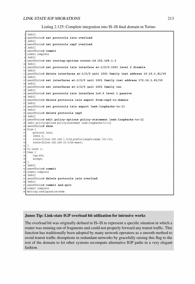
LINK-STATE IGP MIGRATIONS 213
Listing 2.125: Complete integration into IS–IS final domain in Torino
1 [edit]2 user@Torino# set protocols isis overload3 [edit]4 user@Torino# set protocols ospf overload5 [edit]6 user@Torino# commit7 commit complete8 [edit]9 user@Torino# set routing-options router-id 192.168.1.3
10 [edit]11 user@Torino# set protocols isis interface at-1/2/0.1001 level 2 disable12 [edit]13 user@Torino# delete interfaces at-1/2/0 unit 1001 family inet address 10.10.1.81/3014 [edit]15 user@Torino# set interfaces at-1/2/0 unit 1001 family inet address 172.16.1.81/3016 [edit]17 user@Torino# set interfaces at-1/2/0 unit 1001 family iso18 [edit]19 user@Torino# set protocols isis interface lo0.0 level 1 passive20 [edit]21 user@Torino# delete protocols isis export from-ospf-to-domain22 [edit]23 user@Torino# set protocols isis export leak-loopbacks-to-l124 [edit]25 user@Torino# delete protocols ospf26 [edit]27 user@Torino# edit policy-options policy-statement leak-loopbacks-to-l128 [edit policy-options policy-statement leak-loopbacks-to-l1]29 user@Torino# show30 from {31 protocol isis;32 level 2;33 route-filter 192.168.1.0/24 prefix-length-range /32-/32;34 route-filter 192.168.10.0/24 exact;35 }36 to level 1;37 then {38 tag 400;39 accept;40 }41 [edit]42 user@Torino# commit43 commit complete44 [edit]45 user@Torino# delete protocols isis overload46 [edit]47 user@Torino# commit and-quit48 commit complete49 Exiting configuration mode
Junos Tip: Link-state IGP overload bit utilization for intrusive works
The overload bit was originally defined in IS–IS to represent a specific situation in which arouter was running out of fragments and could not properly forward any transit traffic. Thisfunction has traditionally been adopted by many network operators as a smooth method toavoid transit traffic disruptions in redundant networks by gracefully raising this flag to therest of the domain to let other systems recompute alternative IGP paths in a very elegantfashion.
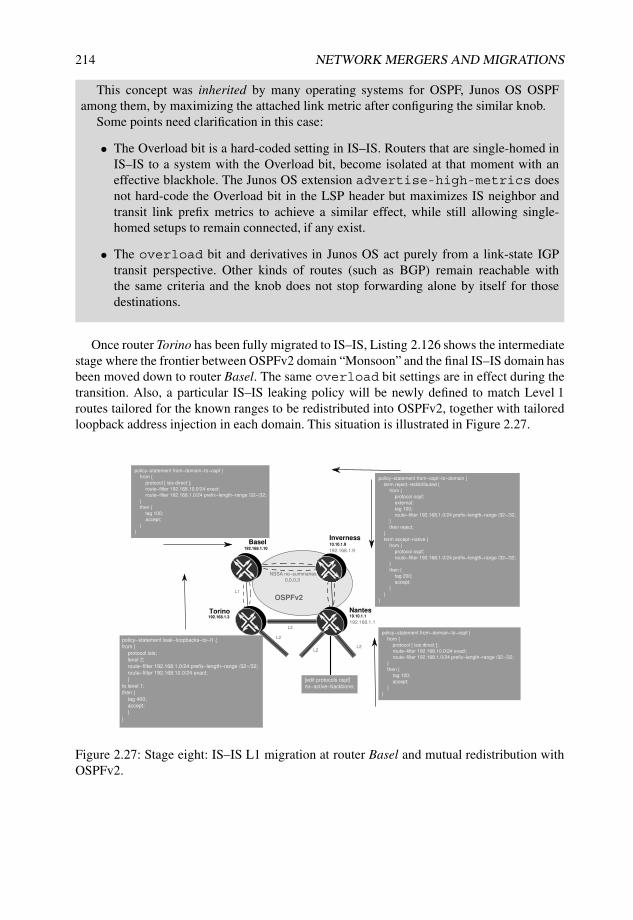
214 NETWORK MERGERS AND MIGRATIONS
This concept was inherited by many operating systems for OSPF, Junos OS OSPFamong them, by maximizing the attached link metric after configuring the similar knob.
Some points need clarification in this case:
• The Overload bit is a hard-coded setting in IS–IS. Routers that are single-homed inIS–IS to a system with the Overload bit, become isolated at that moment with aneffective blackhole. The Junos OS extension advertise-high-metrics doesnot hard-code the Overload bit in the LSP header but maximizes IS neighbor andtransit link prefix metrics to achieve a similar effect, while still allowing single-homed setups to remain connected, if any exist.
• The overload bit and derivatives in Junos OS act purely from a link-state IGPtransit perspective. Other kinds of routes (such as BGP) remain reachable withthe same criteria and the knob does not stop forwarding alone by itself for thosedestinations.
Once router Torino has been fully migrated to IS–IS, Listing 2.126 shows the intermediatestage where the frontier between OSPFv2 domain “Monsoon” and the final IS–IS domain hasbeen moved down to router Basel. The same overload bit settings are in effect during thetransition. Also, a particular IS–IS leaking policy will be newly defined to match Level 1routes tailored for the known ranges to be redistributed into OSPFv2, together with tailoredloopback address injection in each domain. This situation is illustrated in Figure 2.27.
Nantes10.10.1.1
Torino
10.10.1.9
InvernessBasel
192.168.1.3
192.168.1.10
NSSA no−summaries
0.0.0.3
policy−statement from−domain−to−ospf {
from {
protocol [ isis direct ];
route−filter 192.168.10.0/24 exact;
route−filter 192.168.1.0/24 prefix−length−range /32−/32;
}
then {
tag 100;
accept;
}
}
policy−statement from−ospf−to−domain {
term reject−redistributed {
from {
protocol ospf;
external;
tag 100;
route−filter 192.168.1.0/24 prefix−length−range /32−/32;
}
then reject;
}
term accept−native {
from {
protocol ospf;
route−filter 192.168.1.0/24 prefix−length−range /32−/32;
}
then {
tag 200;
accept;
}
}
}OSPFv2
192.168.1.9
192.168.1.1L2
L1
L2
L2L2
policy−statement leak−loopbacks−to−l1 {
from {
protocol isis;
level 2;
route−filter 192.168.1.0/24 prefix−length−range /32−/32;
route−filter 192.168.10.0/24 exact;
}
to level 1;
then {
tag 400;
accept;
}
}
policy−statement from−domain−to−ospf {
from {
protocol [ isis direct ];
route−filter 192.168.10.0/24 exact;
route−filter 192.168.1.0/24 prefix−length−range /32−/32;
}
then {
tag 100;
accept;
}
}
[edit protocols ospf]
no−active−backbone;
Figure 2.27: Stage eight: IS–IS L1 migration at router Basel and mutual redistribution withOSPFv2.

LINK-STATE IGP MIGRATIONS 215
Listing 2.126: IS–IS integration and mutual protocol redistribution in Basel
1 [edit]2 user@Basel# set protocols ospf overload3 [edit]4 user@Basel# commit5 [edit policy-options policy-statement block-non-legitimate-loopback]6 user@Basel# show7 from {8 protocol direct;9 route-filter 10.10.1.10/32 exact; # Avoid own old loopback address
10 }11 then reject;12 [edit policy-options policy-statement from-ospf-to-domain]13 user@Basel# show14 term reject-redistributed {15 from {16 protocol ospf;17 external;18 tag 100;19 route-filter 192.168.1.0/24 prefix-length-range /32-/32;20 }21 then reject; # Avoid already redistributed address to be injected back22 }23 term accept-native {24 from {25 protocol ospf;26 route-filter 192.168.1.0/24 prefix-length-range /32-/32;27 }28 then {29 tag 200;30 accept; # Redistribute native legitimate loopback addresses from domain31 }32 }33 [edit policy-options policy-statement from-domain-to-ospf]34 user@Basel# show35 from {36 protocol [ isis direct ];37 route-filter 192.168.10.0/24 exact; # Remote domain prefix38 route-filter 192.168.1.0/24 prefix-length-range /32-/32; # "Gale Internet" loopback address range39 }40 then {41 tag 100;42 accept;43 }44
45 [edit] # Renumber system and migrate to IS-IS46 user@Basel# set routing-options router-id 192.168.1.1047 [edit]48 user@Basel# delete protocols ospf area 0.0.0.3 interface lo0.049 [edit]50 user@Basel# delete protocols ospf area 0.0.0.3 interface at-0/0/0.100151 [edit protocols ospf]52 user@Basel# set area 0.0.0.3 interface 10.10.1.1053 [edit protocols ospf]54 user@Basel# set export from-domain-to-ospf55 [edit]56 user@Basel# set overload57 [edit]58 user@Basel# set protocols isis level 2 disable59 [edit]60 user@Basel# set protocols isis level 1 authentication-type md561 [edit]62 user@Basel# set protocols isis level 1 authentication-key "Aeris"63 [edit]64 user@Basel# set protocols isis interface lo0.0 level 1 passive65 [edit]66 user@Basel# set protocols isis interface at-0/0/0.100167 [edit]

216 NETWORK MERGERS AND MIGRATIONS
68 user@Basel# set protocols isis level 1 wide-metrics-only69 [edit protocols isis]70 user@Basel# set export [ block-non-legitimate-loopback from-ospf-to-domain ]71 [edit]72 user@Basel# set protocols isis reference-bandwidth 100g73 [edit] # Migrate previous link to outer world from OSPF to IS-IS74 user@Basel# delete interfaces at-0/0/0.1001 family inet address 10.10.1.82/3075 [edit]76 user@Basel# set interfaces at-0/0/0.1001 family inet address 172.16.1.82/3077 [edit]78 user@Basel# set interfaces at-0/0/0.1001 family iso79 [edit] # Add BCD-coded NET-Id80 user@Basel# set interfaces lo0 unit 0 family iso address 49.0003.1921.6800.1010.0081 [edit]82 user@Basel# show protocols isis83 export [ block-non-legitimate-loopback from-ospf-to-domain ];84 reference-bandwidth 100g;85 overload;86 level 2 disable;87 level 1 {88 authentication-key "$9$I7/EhyMWx-b2cyYo"; ### SECRET-DATA89 authentication-type md5;90 wide-metrics-only;91 }92 interface at-0/0/0.1001;93 interface lo0.0 {94 level 1 passive;95 }96 [edit]97 user@Basel# show protocols ospf98 overload;99 export from-domain-to-ospf;
100 reference-bandwidth 100g;101 area 0.0.0.3 {102 nssa no-summaries;103 interface at-0/1/0.1001;104 interface 10.10.1.10;105 }106 [edit]107 user@Basel# commit108 commit complete109 [edit] # Allow back transit traffic after integration110 user@Basel# delete protocols ospf overload111 [edit]112 user@Basel# delete protocols isis overload113 [edit]114 user@Basel# commit and-quit115 commit complete116 Exiting configuration mode117
118 user@Basel> show isis adjacency119 Interface System L State Hold (secs) SNPA120 at-0/0/0.1001 Torino 1 Up 20121
122 user@Basel> show ospf neighbor123 Address Interface State ID Pri Dead124 10.10.1.73 at-0/1/0.1001 Full 10.10.1.9 128 34125
126 user@Basel> show ospf database detail router lsa-id 192.168.1.10127
128 OSPF database, Area 0.0.0.3129 Type ID Adv Rtr Seq Age Opt Cksum Len130 Router *192.168.1.10 192.168.1.10 0x80000007 51 0x20 0xeb38 60131 bits 0x2, link count 3132 id 10.10.1.9, data 10.10.1.74, Type PointToPoint (1)133 Topology count: 0, Default metric: 643134 id 10.10.1.72, data 255.255.255.252, Type Stub (3)135 Topology count: 0, Default metric: 643136 id 10.10.1.10, data 255.255.255.255, Type Stub (3) # Router ID not as Stub route

LINK-STATE IGP MIGRATIONS 217
137 Topology count: 0, Default metric: 0138
139 user@Basel> show ospf database140
141 OSPF database, Area 0.0.0.3142 Type ID Adv Rtr Seq Age Opt Cksum Len143 Router 10.10.1.1 10.10.1.1 0x80000008 2089 0x20 0xe33b 48144 Router 10.10.1.9 10.10.1.9 0x80000019 2500 0x20 0x13ec 96145 Router 10.10.1.10 10.10.1.10 0x80000018 3538 0x20 0x7d30 84146 Router *192.168.1.10 192.168.1.10 0x80000006 1708 0x20 0xed37 60147 Summary 0.0.0.0 10.10.1.1 0x80000001 2089 0x20 0x54ca 28 # Default route from
Nantes148 NSSA 192.168.1.1 10.10.1.1 0x80000008 1322 0x20 0x8540 36149 NSSA *192.168.1.1 192.168.1.10 0x80000002 1445 0x28 0xacee 36150 NSSA 192.168.1.3 10.10.1.1 0x80000007 1422 0x20 0xb96a 36151 NSSA *192.168.1.3 192.168.1.10 0x80000002 1198 0x28 0x52e7 36152 NSSA 192.168.1.4 10.10.1.1 0x80000007 623 0x20 0x8a4f 36153 NSSA *192.168.1.4 192.168.1.10 0x80000002 951 0x28 0xaeff 36154 <...>155
156 user@Basel> show isis database157 IS-IS level 1 link-state database:158 LSP ID Sequence Checksum Lifetime Attributes159 Torino.00-00 0x54 0x7aab 454 L1 L2 Attached160 Basel.00-00 0x3 0x3393 513 L1161 2 LSPs162
163 IS-IS level 2 link-state database:164 0 LSPs165
166 user@Basel> show isis database detail167 IS-IS level 1 link-state database:168
169 Torino.00-00 Sequence: 0x54, Checksum: 0x7aab, Lifetime: 452 secs170 IS neighbor: Basel.00 Metric: 160171 IP prefix: 172.16.1.80/30 Metric: 160 Internal Up172 IP prefix: 192.168.1.1/32 Metric: 160 Internal Down173 IP prefix: 192.168.1.3/32 Metric: 0 Internal Up174 IP prefix: 192.168.1.4/32 Metric: 903 Internal Down175 IP prefix: 192.168.1.6/32 Metric: 1546 Internal Down176 IP prefix: 192.168.1.7/32 Metric: 1556 Internal Down177 IP prefix: 192.168.1.8/32 Metric: 260 Internal Down178 IP prefix: 192.168.1.20/32 Metric: 903 Internal Down179 IP prefix: 192.168.1.21/32 Metric: 1556 Internal Down180 IP prefix: 192.168.10.0/24 Metric: 1556 Internal Down181
182 Basel.00-00 Sequence: 0x3, Checksum: 0x3393, Lifetime: 510 secs183 IS neighbor: Torino.00 Metric: 10184 IP prefix: 172.16.1.80/30 Metric: 10 Internal Up185 IP prefix: 192.168.1.9/32 Metric: 643 Internal Up186 IP prefix: 192.168.1.10/32 Metric: 0 Internal Up187
188 IS-IS level 2 link-state database:189
190 user@Basel> show route protocol ospf active-path table inet.0191
192 inet.0: 27 destinations, 39 routes (27 active, 0 holddown, 0 hidden)193 + = Active Route, - = Last Active, * = Both194
195 0.0.0.0/0 *[OSPF/10] 00:35:05, metric 1296 # Active route preferred from Nantes196 > via at-0/1/0.1001197 10.10.1.9/32 *[OSPF/10] 00:41:45, metric 643198 > via at-0/1/0.1001199 10.10.1.64/30 *[OSPF/10] 00:41:45, metric 1286200 > via at-0/1/0.1001201 192.168.1.9/32 *[OSPF/10] 00:41:45, metric 643202 > via at-0/1/0.1001203 224.0.0.5/32 *[OSPF/10] 15:22:34, metric 1204 MultiRecv

218 NETWORK MERGERS AND MIGRATIONS
205
206 user@Basel> show route protocol isis active-path table inet.0207
208 inet.0: 27 destinations, 39 routes (27 active, 0 holddown, 0 hidden)209 + = Active Route, - = Last Active, * = Both210
211 # External routes preferred via IS-IS212
213 192.168.1.1/32 *[IS-IS/18] 00:39:26, metric 170, tag 400214 > to 172.16.1.81 via at-0/0/0.1001215 192.168.1.3/32 *[IS-IS/15] 00:39:26, metric 10216 > to 172.16.1.81 via at-0/0/0.1001217 192.168.1.4/32 *[IS-IS/18] 00:39:26, metric 913, tag 400218 > to 172.16.1.81 via at-0/0/0.1001219 192.168.1.6/32 *[IS-IS/18] 00:39:26, metric 1556, tag 400220 > to 172.16.1.81 via at-0/0/0.1001221 192.168.1.7/32 *[IS-IS/18] 00:39:26, metric 1566, tag 400222 > to 172.16.1.81 via at-0/0/0.1001223 192.168.1.8/32 *[IS-IS/18] 00:39:26, metric 270, tag 400224 > to 172.16.1.81 via at-0/0/0.1001225 192.168.1.20/32 *[IS-IS/18] 00:39:26, metric 913, tag 400226 > to 172.16.1.81 via at-0/0/0.1001227 192.168.1.21/32 *[IS-IS/18] 00:39:26, metric 1566, tag 400228 > to 172.16.1.81 via at-0/0/0.1001229 192.168.10.0/24 *[IS-IS/18] 00:39:26, metric 1566, tag 400230 > to 172.16.1.81 via at-0/0/0.1001
Note that LSAs injected by router Basel include the legitimate “Gale Internet” loopbackaddress as Advertising Router, which is not injected as part of its Type 1 Router LSA but asanother separate Type 7 NSSA AS External LSA, by means of the OSPFv2 export policyat router Basel.
While it could be argued that a valid transient situation could be built up with Type 7NSSA AS External LSAs relying on other Type 7 NSSA AS External LSAs for reachability,our selective loopback injection has avoided that discussion, as shown in Listing 2.127 fromrouter Inverness’ perspective, because the Forwarding Address field is properly filled with theinternal loopback address as per [RFC2328] (Line 12) and such Type 7 NSSA AS ExternalLSAs remain eligible for forwarding, independently of the situation of the Advertising RouterType 7 NSSA AS External LSAs.
Listing 2.127: Route selection in Inverness during IS–IS transition
1 user@Inverness> show ospf database nssa lsa-id 192.168.1.1 detail2
3 OSPF database, Area 0.0.0.34 Type ID Adv Rtr Seq Age Opt Cksum Len5 NSSA 192.168.1.1 10.10.1.1 0x80000009 363 0x20 0x8341 366 mask 255.255.255.2557 Topology default (ID 0)8 Type: 2, Metric: 0, Fwd addr: 0.0.0.0, Tag: 0.0.0.1009 NSSA 192.168.1.1 192.168.1.10 0x80000003 363 0x28 0xaaef 36
10 mask 255.255.255.25511 Topology default (ID 0)12 Type: 2, Metric: 170, Fwd addr: 10.10.1.10, Tag: 0.0.0.10013 # Forwarding Address pointing to internal valid loopback14
15 user@Inverness> show route protocol ospf table inet.016
17 inet.0: 32 destinations, 34 routes (32 active, 0 holddown, 0 hidden)18 + = Active Route, - = Last Active, * = Both19
20 0.0.0.0/0 *[OSPF/10] 00:42:31, metric 65321 > via so-0/0/1.022 10.10.1.10/32 *[OSPF/10] 15:26:50, metric 643

LINK-STATE IGP MIGRATIONS 219
23 > via at-0/1/0.100124 10.10.1.64/30 [OSPF/10] 04:20:21, metric 64325 > via so-0/0/1.026 10.10.1.72/30 [OSPF/10] 15:26:50, metric 64327 > via at-0/1/0.100128 192.168.1.1/32 *[OSPF/150] 04:20:20, metric 0, tag 10029 > via so-0/0/1.030 192.168.1.3/32 *[OSPF/150] 00:46:45, metric 10, tag 10031 > via at-0/1/0.100132 192.168.1.4/32 *[OSPF/150] 04:20:05, metric 743, tag 10033 > via so-0/0/1.034 192.168.1.6/32 *[OSPF/150] 04:19:57, metric 1386, tag 10035 > via so-0/0/1.036 192.168.1.7/32 *[OSPF/150] 04:19:56, metric 1396, tag 10037 > via so-0/0/1.038 192.168.1.8/32 *[OSPF/150] 04:20:05, metric 100, tag 10039 > via so-0/0/1.040 192.168.1.10/32 *[OSPF/150] 00:49:11, metric 0, tag 10041 > via at-0/1/0.100142 192.168.1.20/32 *[OSPF/150] 04:20:05, metric 743, tag 10043 > via so-0/0/1.044 192.168.1.21/32 *[OSPF/150] 04:19:51, metric 1396, tag 10045 > via so-0/0/1.046 192.168.10.0/24 *[OSPF/150] 04:19:56, metric 1396, tag 10047 > via so-0/0/1.048 224.0.0.5/32 *[OSPF/10] 15:26:55, metric 149 MultiRecv
Junos Tip: Leaking L1 routes with wide-metrics-only
The indirect effect of wide-metrics-only in our topology is that all redistributedroutes from domain “Monsoon” OSPFv2 into IS–IS Level 1 are considered to be internal.This means that default route population policies across IS–IS hierarchies suffice to be ableto flood them to the rest of the network.
In case we did not have wide-metrics-only for IS–IS Level 1, an additional route-leaking policy would be needed at L1L2 systems, router Torino in this intermediate case,to override default behavior and flood loopbacks across the complete setup.
Similar steps are taken until domain “Monsoon” is fully integrated into the final IS–ISdomain. Progress can be easily identified by monitoring the remaining active OSPFv2 routeson router Nantes, as per Listing 2.128 when only the remaining link to router Inverness wasin OSPFv2 NSSA 0.0.0.3 (the OSPFv2 backbone connection in Area 0.0.0.0 to router Torinowas previously dismantled).
Listing 2.128: Latest OSPFv2 remaining information in Nantes prior to dismantling
1 user@Nantes> show ospf database2
3 OSPF database, Area 0.0.0.0 # Area 0 only includes own LSAs4 Type ID Adv Rtr Seq Age Opt Cksum Len5 Router *10.10.1.1 10.10.1.1 0x8000000e 47 0x22 0x922b 486 Summary *10.10.1.9 10.10.1.1 0x80000004 45 0x22 0xa0df 287 Summary *10.10.1.64 10.10.1.1 0x80000002 47 0x22 0x6ae3 288 ASBRSum *192.168.1.9 10.10.1.1 0x80000004 45 0x22 0xdb4e 289
10 OSPF database, Area 0.0.0.3 # Area 3 just includes own and Inverness’ LSAs from legitimateloopback
11 Type ID Adv Rtr Seq Age Opt Cksum Len12 Router *10.10.1.1 10.10.1.1 0x80000010 47 0x20 0xc7f9 4813 Router 192.168.1.9 192.168.1.9 0x8000000a 28 0x20 0x7147 72

220 NETWORK MERGERS AND MIGRATIONS
14 Summary *0.0.0.0 10.10.1.1 0x80000005 47 0x20 0x4cce 2815 NSSA *192.168.1.1 10.10.1.1 0x8000000e 47 0x20 0x7946 3616 NSSA 192.168.1.1 192.168.1.9 0x80000002 48 0x28 0x52eb 3617 NSSA *192.168.1.3 10.10.1.1 0x8000000d 47 0x20 0xad70 3618 NSSA 192.168.1.3 192.168.1.9 0x80000002 48 0x28 0xf7e4 3619 <...>20 NSSA *192.168.1.21 10.10.1.1 0x8000000b 47 0x20 0x70c4 3621 NSSA 192.168.1.21 192.168.1.9 0x80000002 48 0x28 0x426e 3622 NSSA *192.168.10.0 10.10.1.1 0x8000000b 47 0x20 0xdf61 3623 NSSA 192.168.10.0 192.168.1.9 0x80000002 48 0x28 0xb10b 3624 OSPF AS SCOPE link state database25 Type ID Adv Rtr Seq Age Opt Cksum Len26 Extern *192.168.1.1 10.10.1.1 0x80000013 45 0x22 0x385a 3627 Extern *192.168.1.3 10.10.1.1 0x80000013 45 0x22 0xdd53 3628 Extern *192.168.1.4 10.10.1.1 0x80000013 45 0x22 0x3a6b 3629 <...>30 Extern *192.168.1.20 10.10.1.1 0x80000012 45 0x22 0x9bfa 3631 Extern *192.168.1.21 10.10.1.1 0x80000011 45 0x22 0x2cda 3632 Extern *192.168.10.0 10.10.1.1 0x80000011 45 0x22 0x9b77 3633
34 user@Nantes> show route protocol ospf active-path table inet.035
36 inet.0: 45 destinations, 58 routes (45 active, 0 holddown, 0 hidden)37 + = Active Route, - = Last Active, * = Both38
39 10.10.1.9/32 *[OSPF/10] 00:00:49, metric 64340 > via so-1/0/1.041 224.0.0.5/32 *[OSPF/10] 4d 23:49:14, metric 142 MultiRecv
At this point, non-legitimate loopback addresses and IS–IS export policies to inject validloopback addresses or redistribute OSPFv2 can safely be removed without any impact. Notethat specific IS–IS Level 2 to Level 1 route-leaking policies need to remain for optimalrouting purposes. This is depicted in Figure 2.28.
Nantes192.168.1.1
Torino
192.168.1.9
InvernessBasel
192.168.1.3
192.168.1.10
L2
L1
L2
L2L2
policy−statement leak−loopbacks−to−l1 {
from {
protocol isis;
level 2;
route−filter 192.168.1.0/24 prefix−length−range /32−/32;
route−filter 192.168.10.0/24 exact;
}
to level 1;
then {
tag 400;
accept;
}
}
L1
L1
Figure 2.28: Stage eight: final IS–IS status and L2 to L1 leaking at domain “Monsoon”.

LINK-STATE IGP MIGRATIONS 221
2.3.12 Stage nine: IS–IS Level 1 authentication and route-leakingadaption in domain “Mistral” and router Lille
This last migration step mainly consists of adapting the IS–IS Level 1 authentication key tothe final value Aeris and fine-tuning the remaining leaking policy at router Livorno to removeOSPFv2 route injection, given that no more OSPFv2 active routes are in place.
Keeping the same rationale in mind, the idea is to perform authentication transition in asmooth manner, which can be achieved by means of the IS–IS no-authentication-check knob in Junos OS in the following sequence:
• Activate no-authentication-check knob in all participating systems, includ-ing router Lille.
• Adapt Level 1 authentication key to Aeris gradually in each system. Remove specificauthentication settings for IIHs on the point-to-point link between router Havana androuter Bilbao for a joint key Aeris for both levels.
• Remove no-authentication-check in each router, resulting in final key Aerisbeing active the entire domain.
The main drawback to this method is that all systems are exposed to accepting IS–IS unauthenticated information (no-authentication-check applies for both levels)during the transition time frame.
Although avoiding authentication checks can be considered as weakness and a potentialbackdoor for attacks, it is assumed that this will be just a transient period of time. Thereis no impact when adding or removing no-authentication-check, and these threeiterations can almost take place consecutively, once sufficient checks are done. Listing 2.129illustrates how adapting authentication information in the system is harmless as long asno-authentication-check remains active (Lines 51, 56, 61, and 66 show a singletransition when activating the adjacency, which occurred several hours ago as indicated inthe Last Transition field).
Listing 2.129: IS–IS Level 1 authentication transition in Havana
1 [edit]2 user@Havana# edit protocols isis3 [edit protocols isis]4 user@Havana# show5 export leak-loopbacks-to-l1;6 reference-bandwidth 100g;7 no-authentication-check;8 level 1 {9 authentication-key "$9$ZAUH.n6A01hCtMX7NY2k.P"; ### SECRET-DATA
10 authentication-type md5;11 wide-metrics-only;12 }13 level 2 {14 authentication-key "$9$JjGUiPfzn9pDitO"; ### SECRET-DATA15 authentication-type md5;16 wide-metrics-only;17 }18 interface fe-0/3/0.0 {19 level 2 disable;20 }21 interface so-1/0/0.0 {22 level 1 disable;

222 NETWORK MERGERS AND MIGRATIONS
23 }24 interface ge-1/1/0.0 {25 level 2 disable;26 }27 interface at-1/2/0.1001 {28 level 1 {29 hello-authentication-key "$9$7W-dwoaUiqfVwPQ"; ### SECRET-DATA30 hello-authentication-type md5;31 }32 }33 interface lo0.0 {34 level 1 passive;35 level 2 passive;36 }37
38 [edit protocols isis]39 user@Havana# set level 1 authentication-key "Aeris"40 [edit protocols isis]41 user@Havana# delete interface at-1/2/0.1001 level 142 [edit protocols isis]43 user@Havana# commit and-quit44
45 # "Last transition field" indicates that adjacencies remained unaffected46 # Only 1 Up/Down transition for all adjacencies47
48 user@Havana> show isis adjacency detail49 Bilbao-re050 Interface: at-1/2/0.1001, Level: 3, State: Up, Expires in 21 secs51 Priority: 0, Up/Down transitions: 1, Last transition: 17:22:06 ago52 Circuit type: 3, Speaks: IP, IPv653 <...>54 Livorno55 Interface: fe-0/3/0.0, Level: 1, State: Up, Expires in 19 secs56 Priority: 64, Up/Down transitions: 1, Last transition: 06:46:16 ago57 Circuit type: 1, Speaks: IP, IPv6, MAC address: 0:14:f6:85:40:5d58 <...>59 male-re060 Interface: ge-1/1/0.0, Level: 1, State: Up, Expires in 22 secs61 Priority: 64, Up/Down transitions: 1, Last transition: 17:17:20 ago62 Circuit type: 1, Speaks: IP, IPv6, MAC address: 0:19:e2:2b:38:fa63 <...>64 Livorno65 Interface: so-1/0/0.0, Level: 2, State: Up, Expires in 23 secs66 Priority: 0, Up/Down transitions: 1, Last transition: 17:22:34 ago67 Circuit type: 2, Speaks: IP, IPv668 <...>
Once this final authentication key has been deployed in all participating systems,no-authentication-check can be safely deleted.
Finally, because no OSPFv2 active routes exist on router Livorno any longer, the existingroute-leaking policy can be normalized and adapted to inject only Level 2 loopback addressesinto IS–IS Level 1 for optimal routing purposes from all internal L1 systems. This is shownin Listing 2.130.
Listing 2.130: Final route-leaking policy adaption at Livorno
1 [edit policy-options policy-statement leak-loopbacks-to-l1]2 lab@Livorno# show3 term isis {4 from {5 protocol isis;6 level 2;7 route-filter 192.168.1.0/24 prefix-length-range /32-/32;8 route-filter 192.168.10.0/24 exact;9 }
10 to level 1;

LINK-STATE IGP MIGRATIONS 223
11 then {12 tag 300;13 accept;14 }15 }16 term ospf {17 from {18 protocol ospf;19 route-filter 192.168.1.0/24 prefix-length-range /32-/32;20 route-filter 192.168.10.0/24 exact;21 }22 to level 1;23 then {24 tag 300;25 accept;26 }27 }28 [edit policy-options policy-statement leak-loopbacks-to-l1]29 lab@Livorno# delete term ospf30 [edit protocols isis]31 lab@Livorno# delete no-authentication-check32
33 user@Livorno> show isis database detail Livorno level 134 IS-IS level 1 link-state database:35
36 Livorno.00-00 Sequence: 0x87, Checksum: 0x81b0, Lifetime: 1154 secs37 IS neighbor: Havana.02 Metric: 100038 IP prefix: 172.16.100.0/24 Metric: 1000 Internal Up39 IP prefix: 192.168.1.1/32 Metric: 1386 Internal Down40 IP prefix: 192.168.1.3/32 Metric: 1546 Internal Down41 IP prefix: 192.168.1.6/32 Metric: 0 Internal Up # Up bit just for own
loopback42 IP prefix: 192.168.1.7/32 Metric: 10 Internal Down # Down bit marked now43 IP prefix: 192.168.1.9/32 Metric: 2029 Internal Down44 IP prefix: 192.168.1.10/32 Metric: 1706 Internal Down45 IP prefix: 192.168.1.21/32 Metric: 10 Internal Down # Down bit marked now46 IP prefix: 192.168.10.0/24 Metric: 10 Internal Down
All these changes for the final stage are depicted in Figure 2.29.
2.3.13 Migration summary
The goal of the case study after all migration steps is summarized in Figure 2.30.While the migration rollout has been lengthy, no customers suffered any impact, except
for the compulsory address renumbering exercises in domain “Monsoon”, which might havebeen executed during a maintenance window on a weekend night.
A parallel exercise that has not been addressed directly in this case study is theenforcement of configuration homogeneity across all domains. While some divergences havebeen analyzed in some stages, such as the adaption of reference-bandwidth and linkcost manipulation for external links from domain “Cyclone”, other important link-state IGPconfiguration aspects, such as timer values or general protocol statements such as SPF optionsor multitopology support, are beyond the scope of this case study, because an in-depthevaluation of each configuration knob would be required. However, this standardization effortis particularly relevant in live networks.
Apart from this, all requirements have been satisfied in a thoughtful manner and meetingdeadlines. While initial connectivity was rapidly deployed, systems have been progressivelyintegrated in a unique and unified IS–IS domain, including internal L1, L1L2, and pure L2systems as per the design.

224 NETWORK MERGERS AND MIGRATIONS
policy−statement leak−loopbacks−to−l1 {
from {
protocol isis;
level 2;
route−filter 192.168.1.0/24 prefix−length−range /32−/32;
route−filter 192.168.10.0/24 exact;
}
to level 1;
then {
tag 300;
accept;
}
}
Male
Bilbao
Havana
192.168.1.20
192.168.1.8
49.0001.1921.6800.1004.00
49.0003.1921.6800.1004.00
L1
L1
L1
49.0001.1921.6800.1008.00
49.0001.1921.6800.1020.00
L2
Livorno192.168.1.6
Lille192.168.1.5
49.0003.1921.6800.1006.00
L2
L2L2
L1
49.0003.1921.6800.1005.00policy−statement leak−loopbacks−to−l1 {
from {
protocol isis;
level 2;
route−filter 192.168.1.0/24 prefix−length−range /32−/32;
route−filter 192.168.10.0/24 exact;
}
to level 1;
then {
tag 300;
accept;
}
}
192.168.1.4
Figure 2.29: Stage nine: final IS–IS status at domain “Mistral” and Lille.
Male
Bilbao
Havana
Nantes
Skopie
Livorno Barcelona
Honolulu
192.168.1.4
192.168.1.20
192.168.1.8
192.168.1.1
192.168.1.2
192.168.1.6192.168.1.7
192.168.1.21
Torino
Lille
192.168.1.9
InvernessBasel
192.168.1.5
192.168.1.3
192.168.1.10
L1
L1
NOC mgmt
center
Area 49.0003
L1
Final IS−IS
domain
Area 49.0003
L2
L2
L2
L2
L2
L2
L1
L1
L1
Area
49.0001
L1 Redistribute
192.168.10.0/24
Cost 1000
Redistribute
192.168.10.0/24
Cost 1001
Adapte
d c
ost
Adapted cost
Adapted cost
L2
Figure 2.30: Final IS–IS topology including metric adaption and redistribution.
Top management of “Gale Internet” are clearly proud of their network engineers!Challenges like such a sensitive link-state IGP integration are not for the faint hearted.But more important are the instructive lessons learned that one can apply to such real-life

LINK-STATE IGP MIGRATIONS 225
migrations. Among other concepts, the following topics have been evaluated, revisited, andput in practice:
• link-state IGP preference adjustment both for internal and external routes;
• external route injection differences when using IS–IS wide-metrics-only whencompared with standard OSPFv2 rules;
• replication of link metric values in IS–IS and OSPFv2, including bandwidth-derivedreferences;
• IS–IS metric calculation and adjustment to adapt OSPFv2 external Type 2 redistribu-tion design;
• TED protocol credibility deployment for encompassed TED information transition;
• selective loopback address injection in OSPFv2 Type 1 Router LSA and IS–IS LSP;
• definition of multiple leaking policies using administrative tag matching and setting;
• control of mutual protocol redistribution in more than a single leaking point;
• alignment of authentication settings for IS–IS Level 1 and Level 2 in a point-to-point link and tweaking per-level hello-authentication;
• identification of IS–IS ATTached bit setting conditions;
• area stitching in a joint IS–IS Level 1 and respective route selection;
• identification of IS–IS Up/Down bit setting conditions and possible consequences;
• protocol preference and TED credibility transition without affecting RSVPneighbor relationships or LSPs;
• identification of a safeguard mechanism against protocol transition to IS–IS to avoidaccidental leaking;
• progressive intrusive migration into an existing domain, including route redistributionand protocol redefinition to mirror previous area definition and forwarding paths;
• replication of standalone default route selection by tweaking OSPF active backbonedetection during migration;
• utilization of both OSPFv2 and IS–IS overload settings for intrusive maintenanceworks;
• IS–IS per-level authentication changes by means of transient deactivation and progres-sive rollout of a new MD5 key.

226 NETWORK MERGERS AND MIGRATIONS
Bibliography
[ISO10589] ISO. ISO/IEC 10589:2002, Intermediate system to intermediate systemrouting information exchange protocol for use in conjunction with the protocolfor providing the connectionless-mode network service (ISO 8473), 2002.
[RFC1131] J. Moy. OSPF specification. RFC 1131 (Proposed Standard), October 1989.Obsoleted by RFC 1247.
[RFC1195] R. W. Callon. Use of OSI IS-IS for routing in TCP/IP and dual environments.RFC 1195 (Proposed Standard), December 1990. Updated by RFCs 1349,5302, 5304.
[RFC1584] J. Moy. Multicast Extensions to OSPF. RFC 1584 (Historic), March 1994.
[RFC1918] Y. Rekhter, B. Moskowitz, D. Karrenberg, G. J. de Groot, and E. Lear.Address Allocation for Private Internets. RFC 1918 (Best Current Practice),February 1996.
[RFC2328] J. Moy. OSPF Version 2. RFC 2328 (Standard), April 1998.
[RFC2740] R. Coltun, D. Ferguson, and J. Moy. OSPF for IPv6. RFC 2740 (ProposedStandard), December 1999. Obsoleted by RFC 5340.
[RFC2966] T. Li, T. Przygienda, and H. Smit. Domain-wide Prefix Distribution with Two-Level IS-IS. RFC 2966 (Informational), October 2000. Obsoleted by RFC5302.
[RFC2973] R. Balay, D. Katz, and J. Parker. IS-IS Mesh Groups. RFC 2973 (Informa-tional), October 2000.
[RFC3101] P. Murphy. The OSPF Not-So-Stubby Area (NSSA) Option. RFC 3101(Proposed Standard), January 2003.
[RFC3107] Y. Rekhter and E. Rosen. Carrying Label Information in BGP-4. RFC 3107(Proposed Standard), May 2001.
[RFC3137] A. Retana, L. Nguyen, R. White, A. Zinin, and D. McPherson. OSPF StubRouter Advertisement. RFC 3137 (Informational), June 2001.
[RFC3509] A. Zinin, A. Lindem, and D. Yeung. Alternative Implementations of OSPFArea Border Routers. RFC 3509 (Informational), April 2003.
[RFC3630] D. Katz, K. Kompella, and D. Yeung. Traffic Engineering (TE) Extensions toOSPF Version 2. RFC 3630 (Proposed Standard), September 2003. Updatedby RFC 4203.
[RFC3784] H. Smit and T. Li. Intermediate System to Intermediate System (IS-IS)Extensions for Traffic Engineering (TE). RFC 3784 (Informational), June2004. Obsoleted by RFC 5305, updated by RFC 4205.
[RFC4105] J.-L. Le Roux, J.-P. Vasseur, and J. Boyle. Requirements for Inter-Area MPLSTraffic Engineering. RFC 4105 (Informational), June 2005.
[RFC4203] K. Kompella and Y. Rekhter. OSPF Extensions in Support of GeneralizedMulti-Protocol Label Switching (GMPLS). RFC 4203 (Proposed Standard),October 2005.

LINK-STATE IGP MIGRATIONS 227
[RFC4206] K. Kompella and Y. Rekhter. Label Switched Paths (LSP) Hierarchy withGeneralized Multi-Protocol Label Switching (GMPLS) Traffic Engineering(TE). RFC 4206 (Proposed Standard), October 2005.
[RFC4811] L. Nguyen, A. Roy, and A. Zinin. OSPF Out-of-Band Link State Database(LSDB) Resynchronization. RFC 4811 (Informational), March 2007.
[RFC4915] P. Psenak, S. Mirtorabi, A. Roy, L. Nguyen, and P. Pillay-Esnault. Multi-Topology (MT) Routing in OSPF. RFC 4915 (Proposed Standard), June 2007.
[RFC4970] A. Lindem, N. Shen, J.-P. Vasseur, R. Aggarwal, and S. Shaffer. Extensionsto OSPF for Advertising Optional Router Capabilities. RFC 4970 (ProposedStandard), July 2007.
[RFC5120] T. Przygienda, N. Shen, and N. Sheth. M-ISIS: Multi Topology (MT) Routingin Intermediate System to Intermediate Systems (IS-ISs). RFC 5120(Proposed Standard), February 2008.
[RFC5130] S. Previdi, M. Shand, and C. Martin. A Policy Control Mechanism in IS-ISUsing Administrative Tags. RFC 5130 (Proposed Standard), February 2008.
[RFC5151] A. Farrel, A. Ayyangar, and J.-P. Vasseur. Inter-Domain MPLS and GMPLSTraffic Engineering – Resource Reservation Protocol-Traffic Engineering(RSVP-TE) Extensions. RFC 5151 (Proposed Standard), February 2008.
[RFC5185] S. Mirtorabi, P. Psenak, A. Lindem, and A. Oswal. OSPF Multi-Area Adja-cency. RFC 5185 (Proposed Standard), May 2008.
[RFC5250] L. Berger, I. Bryskin, A. Zinin, and R. Coltun. The OSPF Opaque LSAOption. RFC 5250 (Proposed Standard), July 2008.
[RFC5283] B. Decraene, J.-L. Le Roux, and I. Minei. LDP Extension for Inter-Area LabelSwitched Paths (LSPs). RFC 5283 (Proposed Standard), July 2008.
[RFC5305] T. Li and H. Smit. IS-IS Extensions for Traffic Engineering. RFC 5305(Proposed Standard), October 2008. Updated by RFC 5307.
[RFC5308] C. Hopps. Routing IPv6 with IS-IS. RFC 5308 (Proposed Standard), October2008.
[RFC5309] N. Shen and A. Zinin. Point-to-Point Operation over LAN in Link StateRouting Protocols. RFC 5309 (Informational), October 2008.
Further Reading
[1] Aviva Garrett. JUNOS Cookbook, April 2006. ISBN 0-596-10014-0.
[2] Matthew C. Kolon and Jeff Doyle. Juniper Networks Routers : The Complete Reference,February 2002. ISBN 0-07-219481-2.
[3] James Sonderegger, Orin Blomberg, Kieran Milne, and Senad Palislamovic. JUNOSHigh Availability, August 2009. ISBN 978-0-596-52304-6.

228 NETWORK MERGERS AND MIGRATIONS
[4] Hannes Gredler and Walter Goralski. The Complete IS-IS Routing Protocol, January2005. ISBN 1-85233-822-9.
[5] Jeff Doyle and Jennifer Carroll. Routing TCP/IP, Volume 1, October 2005. ISBN 978-1587052026.
[6] Jeff Doyle. OSPF and IS-IS: Choosing an IGP for Large-Scale Networks, November2005. ISBN 978-0321168795.

3
BGP Migrations
The Border Gateway Protocol (BGP) came to standardized life in 1989 with [RFC1105].After more than 20 years of its initial specification, BGP, meant to be a short-term solutionawaiting some yet-to-be-determined long-term solution for the inter-domain routing, is stillvery young and healthy. Production implementations of the protocol have been deployedsince 1990. The most current specification of the BGP protocol at the time of this writing isstill considered to be version 4 as per [RFC4271], thanks to the embedded extensibility. Thischapter considers this version to be the current and most widely deployed one.
Figure 3.1 shows an example of a BGP network composed of interconnected AutonomousSystems (ASs), each with its own address space, that exchange reachability information.The AS number is carried with the advertisements in the form of the AS_PATH attribute,providing loop capability detection.
Integration or division of organizations implies changes in the AS number of theBGP-speaking network devices interconnecting with external peers. AS renumbering is aninfrequent yet cumbersome task, with most expertise residing in the technical departments ofnetwork integrators or Service Providers that merged smaller ISPs during the consolidationphase after the Internet boom.
Various internal peering topologies are possible. Smaller ASs (or networks with highlyscalable equipment) follow a full-mesh arrangement. Following the example in Figure 3.1,the confederation built within AS64501 is composed of two sub-AS numbers not exposedto other domains and that prevent internal loops. AS65550 implements route reflection,allowing routers within the domain to have routing visibility with just peering sessions tothe reflectors.
The success of BGP as a vehicle to interconnect routing administrations identified by anAS has required the extension of the 16-bit AS number (two bytes, up to AS65535) to 32-bit.Interaction between 2-byte ASs and 4-byte ASs has been embedded in the protocol extensionto allow migration and coexistence.
Renumbering ASs and switching internal topologies considering Confederations, RouteReflectors, or flat full mesh, are the most common migration scenarios.
Network Mergers and Migrations Gonzalo Gómez Herrero and Jan Antón Bernal van der Venc© 2010 John Wiley & Sons, Ltd

230 NETWORK MERGERS AND MIGRATIONS
RR RR
AS64501
AS65550
AS65555
AS65530 AS64511 AS65550
sub−AS
65000
sub−AS
65001
Figure 3.1: Reliable and loop-free information distribution with BGP.
Application Note: Use of AS numbers in documentation
The reader may have noticed that most of the AS numbers used throughout this book spanthe autonomous system number range used for documentation purposes, [RFC5398], whichincludes provisions for both 2-byte and 4-byte numbers. The 2-byte range is adjacent to theprivate AS range defined in [RFC1930] and is typically used as a confederation membersub-AS or for private inter-AS arrangements. Figure 3.2 summarizes the allocation.
1 429496729564512 − 65535
private useRFC1930
65536 − 65551
documentationRFC5398
64496 − 65511
documentationRFC5398
16−bit (2−byte) AS number space
16 AS 1024 AS 16 AS
32−bit (4−byte) AS number space
Figure 3.2: Special allocations for autonomous system numbers.
Use of this reserved space of AS numbers prevents accidental configuration of alreadyassigned AS numbers in production networks. Level3 communications (AS1), Universityof Delaware (AS2), and Massachusetts Institute of Technology (AS3) are some obviousbeneficiaries.

BGP MIGRATIONS 231
Following the general structure of the book, this chapter first describes the motivationsfor BGP migrations, giving practical cases that might justify the migration effort. A sectionon considerations analyzes specific protocol behaviors that have to be understood beforetackling a migration, followed by strategies to consider when undertaking this effort. Detailsabout Junos OS implementation provide a glimpse of the internals of the system. Thanks tothe history of Junos OS in BGP networks, a bag of tools described in the resource section ismade available to satisfy corner-case migration requirements.
The case study in this chapter is aligned with case studies in other chapters of the bookand simulates the acquisition of a Service Provider, using BGP confederations for a fastintegration in an initial stage, followed by a subsequent autonomous system integration usingroute reflection.
3.1 Motivations for BGP Migrations
From a control plane perspective, BGP changes may involve software and router configu-ration: new software may be required to support new or enhanced functionality (the latestimplementation of an RFC); configuration changes may be a consequence of new or alteredinternal topological arrangements, or external factors such as business interconnections. Nomatter why, the underlying reason for a BGP protocol change is usually because it mattersfrom a business perspective. Operational efficiency, new services, and scalability are justsome examples that justify modifying existing environments.
The following sections, while by no means comprehensive, provide an overall view of theelements that are worth considering.
Change in AS identifier
This item is one of the most tedious changes to face during asset acquisition. The bookmaintains a strong focus on the BGP behaviors, covering administrative considerations onlybriefly. This motivation is one of the pillars of the case study to follow.
Modification of internal topologies
If route reflection [RFC4456] or confederations [RFC5065] or both, are not already intro-duced in the original network design, a successful business may have to migrate to one orboth to support growth of the business. All these BGP scalability measures accommodatenetwork growth.
Internal BGP reconfiguration after a merger or acquisition may be required. Mergingtogether two ASs might yield a mixed infrastructure, which may require the aforementionedscalability measures. The same measures may be worth taking if any of the networks are notfully meshed internally, building a confederation for fast integration, dismantling it to providea homogeneous result, or using route reflection clusters for direct integration of commonservices that require minimal infrastructure deployment.

232 NETWORK MERGERS AND MIGRATIONS
Robustness and performance
Keeping all eggs in the same basket for different services might not be a wise decision. Theadditional cost of introducing multiple route reflectors might be offset against the cost oflosing a critical service as a result of the misbehavior of a standard service. As an example,having each route reflector be responsible for a single service may be a good lesson learnedfrom past incidents where heavy routing churn of the Internet service affected businesscustomers using VPN services. Besides robustness, per-service scalability of the controlplane provides performance benefits that allow separate growth paths for different services.
Support of new applications
BGP can be used as the delivery channel for new services. Once the foundation layerfor the routing database is in place, additional data sets can peruse the infrastructure ina straightforward way. The BGP capabilities option as per [RFC3392], used during BGPsession establishment, allows for a negotiated agreement of features. Support of BGP MPLSVPNs in the enterprise is one such example. Proposals of data center interconnections areslowly moving away from Layer 2 switching with Spanning Tree in the wide area to anMPLS backbone with BGP as the control plane supporting a Layer 2 (L2) VPN or VirtualPrivate LAN Service (VPLS), incorporating the data center requirements into a stable andreliable MPLS VPN core.
Support of 4-byte AS numbers
Public AS identifiers were extended to 32 bits with [RFC4893]. Although the specificationcalls for a transition mechanism, adding full support may likely imply changing the softwareimplementation. A one-shot upgrade of the network is unrealistic, so the specificationincludes embedded support for a long transition period.
Routing policy modifications
Changes in routing policies can be perceived as a modification of the database contents. InJunos OS, this routing database is the RIB. For a critical network in continuous operation,any BGP routing change that involves altering traffic is carefully analyzed, and the properstrategy that considers minimal impact to be a critical metric is evaluated. The most commonchange in routing policy consists of moving traffic to follow either the closest or furthest exitfor a specific destination. In the trade, this is called hot potato (hand off as soon as possible)and cold potato (hand off as late as possible) routing. Interestingly enough, routing policiesare outside the scope of the protocol specification; lack of standardization provides a lot offlexibility, along with some side effects, as seen in [BGP-WEDGE].
Summarizing from a BGP transport protocol perspective, a change in the internal BGPinfrastructure (such as the session topology or the introduction of a new service) and a changein the global identifier (AS Number) are the most common motivations for considering amigration of the BGP protocol. Changes in the contents of the exchanged information arepart of using the protocol itself and are considered in the broader context of migration of theservices provided by the protocol.

BGP MIGRATIONS 233
3.2 Considerations for BGP Migrations
BGP is a database exchange protocol, featuring peer flow control and information floodingwith loop avoidance. As a lesson learned from the past, the structure of the informationthat is distributed follows a variable encoding paradigm using TLV elements, which allowsfor extensibility. The information is qualified with an Address Family Identifier (AFI) anda Subsequent Address Family Identifier (SAFI) to identify the payload (for example, IPv4,IPv6, and NSAP), which makes BGP suitable as the transport protocol for a wide variety ofapplications.
For vanilla BGP, the data exchanged in this database is reachability information, taggedwith a flexible list of attributes. New applications, such as VPLS and Route Target(RT) constraints, give different semantics to the exchanged data. Instead of reachability,VPLS exchanges membership information for autodiscovery and signaling. RT constraintsexchange RT membership information. Hence, the data exchanged for these new applicationsis not reachability, but rather membership.
The BGP protocol focuses on the exchange of information and relies on TCP to providereliable transport and flow control. As a hard-state protocol, BGP exchanges informationonly when needed, with no periodic exchanges, unlike protocols such as PIM, RSVP, or RIP.BGP designers considered that periodically readvertising known information using duplicateupdates in a database of this size would not be scalable. A bare-bones keepalive messagetickles the TCP connection to ensure that the session is still alive, but it is quickly suppressedif other information is exchanged within the response interval.
Avoiding routing loops is instrumental to ensuring a stable, loop-free packet forwardingenvironment. BGP avoids loops with the introduction of an attribute that records the AS paththat the information has traversed.
Although BGP has grown up over the years, it is still evolving. The base specificationhas been complemented with extensions for authentication with [RFC2385], capabilityadvertisement mechanisms with [RFC3392], route refresh techniques with [RFC2918], andmultiprotocol extensions with [RFC4760], to name a few, with additional proposals still beingconsidered, such as [ID-ADVISORY]. The IETF Interdomain Routing charter [IETF-IDR]contains a complete listing of work, both standardized and in progress, related to BGP.
New feature introduction can be addressed incrementally thanks to BGP capabilityadvertisement, as defined in [RFC3392]. This flexible mechanism negotiates supportedapplications during connection setup, yielding as a result a common set of capabilities tobe used for the life of the long-lived session. The capability advertisement feature is theunderlying reason that keeps version 4 current, because it loosely decouples combined featuresupport from the protocol version number.
BGP follows a destination-based routing paradigm. In migration scenarios, it is veryattractive to enforce routing policy beyond destination reachability. This is unfortunately (butconsciously) not supported by BGP, because designing the protocol with this added com-plexity was left to the long-term solution. Hence, any migration that involves circumventingthe destination-based paradigm during a transition period entails a fair amount of complexityas additional route views or packets jump between forwarding tables within the system. Thecase study in Section 1.4 on Page 21 offers an example of this complexity.
With BGP’s continuing support for new applications (such as MPLS L3VPNs, VPLS,and VPN autodiscovery), some network engineers still claim that the protocol was devised

234 NETWORK MERGERS AND MIGRATIONS
as a routing protocol and was not meant to carry these types of application. Changing thedefinition of the BGP protocol to a “highly scalable and extensible database distributionprotocol” yields “routing information” as a subset of the possible data types to store in thedatabase; that is, BGP can be used to distribute more information than just IP prefixes.
3.2.1 Protocol messages
BGP uses five messages, namely OPEN, UPDATE, KEEPALIVE, NOTIFICATION, andthe late sibling, REFRESH. Figures 3.3 and 3.4 show the layout of these messages. All themessages start with a common header. Additional extensions to the protocol have managedto squeeze themselves into one of these five messages, reflecting the flexibility of the originaldesign.
BGPMessage
Keepalive
Notification
Refresh
Marker
Marker
Marker
Marker
Marker
Marker
Marker
Value
Variable data
16
16
16
16
16
16
16
2
2
2
2 2
2
2
2 2
1
1
1
1
1
1
1 1 1
1 1
Length
(0)
(2+v)
(2+v) AFI
(0)
Type
(3)
(4)
(5) RSV SAFI
Code Subcode
Variable
Variable
Figure 3.3: KEEPALIVE, NOTIFICATION, and REFRESH BGP protocol messages.
The KEEPALIVE message (Figure 3.3) consists of a BGP header with no further contents,used to indicate liveness of the session. The pace at which these messages are sent out isnegotiated in the OPEN message through the hold time parameter. The protocol has provisionfor using UPDATE messages as a liveness indicator, thus suppressing a KEEPALIVEmessage for busy sessions. A packet protocol capture of a BGP session in the middle ofa full routing advertisement to a BGP client would show UPDATE messages in the forwarddirection, and, in the reverse direction, empty TCP acknowledgment segments would confirmthe data as being received correctly, interleaved with periodic KEEPALIVE messages fromthe client side to maintain the established session. As long as communication occurs inboth directions before the negotiated hold time, the session is kept alive. From a migrationperspective, the hold time indirectly defines the pace of keepalives and is negotiated as thelower of both proposals. Changing the hold time affects both sides of the peering session

BGP MIGRATIONS 235
after session establishment and does not require the configutation of a symmetric value onboth peers.
As an exception mechanism, the specification of the NOTIFICATION message (Figure3.3) aims at detailed reporting of the nature of a problem. All notifications are consideredfatal and terminate the session. The appearance of this message during migrations, otherthan as the results of a subcode 4 Administratively Reset, probably indicates some undesiredprotocol violation. An example of such notification is the report of an unexpected AS numberby the peer. Further examples of notifications are documented in [RFC4271].
The REFRESH message (Figure 3.3), not defined in the original BGP specification, is anew capability that peers can signal, as per [RFC2918]. One peer can request retransmissionof routing information from another peer, and the request can be limited to a subsetof the negotiated applications exchanged. An implementation may keep unused inboundinformation in its RIB-In, which allows a refresh to be performed as a local operation withoutpeer intervention. Compared to the original alternative of restarting a session, the operationaladvantage of the REFRESH mechanism is twofold:
• A policy change on one end may result in no change in the other direction, avoidingthe need for readvertisement in both directions after a session flap. An example ofthe advantage is a service provider that receives customer routes and advertises fullrouting. If the customer receives a new address block, it has to ask the provider tochange its import policy to allow the additional prefix range. Changing the policy andsending a refresh message to receive the new prefix blocks is all that is required by theprovider, instead of restarting the BGP protocol session and readvertising the full routetable.
• Policy changes affecting only one of the protocols do not require total re-initializationof the session when multiprotocol sessions are in use. A typical scenario involves aBGP session sharing Internet and MPLS L3VPN routing information, in which a newimport policy (a new VRF with a new route target community) requires receiving VPNroutes anew.
The OPEN message (Figure 3.4) is the first one sent out after the TCP session is estab-lished. Its main purpose is to exchange configuration information and common parametersto be used throughout the peering session. There needs to be agreement on what version thesession will use. All modern systems implement version 4, so the version field is not likelyto be a factor during migrations. Besides the hold time used by BGP keepalive messagesto verify continuous TCP connectivity, the two elements of special interest in a migrationcontext are the My Autonomous System field, to decide what peering relationship is set up,and the optional capabilities parameter.
Information is maintained by means of UPDATE messages (Figure 3.4). A single messagecan contain both advertisements (for new or updated information) as well as withdrawals. Theprotocol assumes that a more recent advertisement is an implicit withdrawal for previouslysignaled information. The original message considered only IPv4 reachability information.A multiprotocol extension, as described in [RFC4760], added an extra MP_UNREACHattribute to complement the withdrawn routes field and an MP_REACH attribute to specifythe non-IPv4 protocol NLRI information. Because of the reliable nature of the TCP transportlayer, an advertisement is not refreshed periodically. Although the protocol is robust withregards to receiving multiple duplicate update information, this situation should not occur.

236 NETWORK MERGERS AND MIGRATIONS
BGP Header
BGPIdentifier
Opt. parameters
Capabilities are Optional parameter type 2
422222 2222
22
2 11
Hold TimeMy AS
OptLengthVersion
Variable
Variable Variable Variable
Update
Open
Marker
16 2 1
withdrawnLength
Multiprotocol Capability (1)AS−4Byte Capability (65)
MP−REACHAS−PATHLOCAL−PREFMED, ORIGINNEXTHOP
withdrawnroutes
PathAttributes
Network LayerReachability Information
Path Attr.Length
(v) (1)(1)
Figure 3.4: OPEN and UPDATE BGP protocol messages.
3.2.2 Capability advertisement
Learning from past experiences, BGP protocol designers wanted to avoid redefining theprotocol to accommodate new business requirements. Bumping up the version number of theBGP protocol every time a new feature was defined was the minor problem. The challengewas to allow for independent feature support without requiring a combinatorial mix ofprotocol versions. Use of a different version for N features would require 2N version numbersto accommodate all possibilities, yielding a major roadblock for new feature introduction.Adding feature number M would mean that 2M−1 additional versions would need to bedefined, to cover for all combinations of feature M and all previous (M − 1) features enabledsimultaneously.
Through flexible capability advertisement from [RFC3392] procedures, each side of aBGP session advertises its desired interest for the various supported features. Capabilitiesare encoded in the Optional Parameters field of the BGP OPEN message (Figure 3.4), afield that can hold multiple optional parameters. From a migration perspective, knowing thecapabilities of the peer introduces the possibility for incremental change, so this feature isinstrumental to progressive rollout.
Listing 3.1 shows a sample Junos OS BGP protocol trace in which the initial OPENmessage is sent to the peer reporting a list of supported capabilities. Note that this supportcan be restricted, by configuration, to agree only on selected functionality.
Listing 3.1: Indicating peer capabilities in OPEN message
1 Jun 27 19:15:42.295730 BGP SEND 192.168.1.5+49305 -> 192.168.1.20+1792 Jun 27 19:15:42.295766 BGP SEND message type 1 (Open) length 1233 Jun 27 19:15:42.295793 BGP SEND version 4 as 65000 holdtime 90 id 192.168.1.5 parmlen 944 Jun 27 19:15:42.295817 BGP SEND MP capability AFI=1, SAFI=1 # Inet unicast

BGP MIGRATIONS 237
5 Jun 27 19:15:42.296001 BGP SEND Refresh capability, code=128 # Refresh (legacy)6 Jun 27 19:15:42.296022 BGP SEND Refresh capability, code=2 # Refresh (standard)7 Jun 27 19:15:42.296045 BGP SEND Restart capability, code=64, time=120, flags= # Graceful restart8 Jun 27 19:15:42.296069 BGP SEND 4 Byte AS-Path capability (65), as_num 65000 # AS4Byte
A partial summary of the capabilities supported by Junos OS along with the standard thatdescribes the capability is shown in Table 3.1. The capabilities referenced as legacy indicatepre-standard implementations using private capability identifiers greater than 127.
Table 3.1 Some Junos OS BGP capabilities
Capability ID Description Reference
1 Multiprotocol Extensions [RFC4760]2 Route Refresh message [RFC2918]3 Outbound Route Filtering [RFC5291]
64 Graceful Restart [RFC3478]65 4 Byte AS PATH [RFC4893]
128 Route Refresh message legacy130 Outbound Route Filtering legacy
3.2.3 Address families
The Multiprotocol Extension for BGP-4 defined with [RFC4760] was the first capability tobe introduced. Its capability identifier type code 1 highlights this fact. This extension allowsBGP to carry information not just for IPv4 and IPv6 routing, but also for other applications(L3VPN, VPLS, and many more). The BGP protocol originally assumed that fixed formatIPv4 prefixes were part of the withdrawn routes and the NLRI fields in the UPDATE message(Figure 3.4). To allow for new applications, the BGP protocol was extended through theintroduction of two new attributes, MP_REACH and MP_UNREACH, which allowed forvariable-length data types.
Signaling of the different supported applications is performed as different capabilities inthe OPEN message, using the capabilities advertisement procedures discussed previously. Aset of supported applications can be signaled, allowing a common session to share L3VPN,IPv4, IPv6, and any other application. The applications whose information is to be carriedare identified using the AFIs [IANA-AFI] and SAFIs [IANA-SAFI], for which the InternetAssigned Numbers Authority (IANA) holds a regulated registry. Table 3.2 shows a subset ofaddress families supported by Junos OS.
As part of capability advertisement, the common set of supported families is agreed uponbetween both parties in the BGP session. A sample exchange is shown in Listing 3.2. Thereceived UPDATE shows in Line 14 that the peer desires to establish a labeled–unicastrelationship, but this is not configured by the sender, as hinted by the resulting log as shownin Line 19.
After session bringup, the common set of supported capabilities is used for the life of thesession, and the extract can be observed by the operational command starting on Line 25.

238 NETWORK MERGERS AND MIGRATIONS
Listing 3.2: Agreeing on supported applications
1 Jun 26 12:43:13.245764 BGP SEND 172.16.100.8+60939 -> 172.16.100.5+1792 Jun 26 12:43:13.245793 BGP SEND message type 1 (Open) length 593 Jun 26 12:43:13.245817 BGP SEND version 4 as 65511 holdtime 90 id 192.168.1.6 parmlen 304 Jun 26 12:43:13.245836 BGP SEND MP capability AFI=1, SAFI=1 # Family inet5 Jun 26 12:43:13.245853 BGP SEND Refresh capability, code=1286 Jun 26 12:43:13.245870 BGP SEND Refresh capability, code=27 Jun 26 12:43:13.245889 BGP SEND Restart capability, code=64, time=120, flags=8 Jun 26 12:43:13.245909 BGP SEND 4 Byte AS-Path capability (65), as_num 65511}9 Jun 26 12:43:13.247772
10 Jun 26 12:43:13.247772 BGP RECV 172.16.100.5+179 -> 172.16.100.8+6093911 Jun 26 12:43:13.247833 BGP RECV message type 1 (Open) length 6712 Jun 26 12:43:13.247856 BGP RECV version 4 as 65500 holdtime 90 id 192.168.1.5 parmlen 3813 Jun 26 12:43:13.247875 BGP RECV MP capability AFI=1, SAFI=114 Jun 26 12:43:13.247892 BGP RECV MP capability AFI=1, SAFI=4 # Labeled unicast15 Jun 26 12:43:13.247909 BGP RECV Refresh capability, code=12816 Jun 26 12:43:13.247925 BGP RECV Refresh capability, code=217 Jun 26 12:43:13.247944 BGP RECV Restart capability, code=64, time=120, flags=18 Jun 26 12:43:13.247963 BGP RECV 4 Byte AS-Path capability (65), as_num 6550019 Jun 26 12:43:13.248074 bgp_process_caps:20 mismatch NLRI with 172.16.100.5 (External AS 65500):21 peer: <inet-unicast inet-labeled-unicast>(257)22 us: <inet-unicast>(1)23 /* output formatted for clarity */24
25 user@Lille>show bgp neighbor 192.168.1.20 | match nlri26 NLRI for restart configured on peer: inet-unicast inet-labeled-unicast27 NLRI advertised by peer: inet-unicast28 NLRI for this session: inet-unicast
Table 3.2 Selection of address familiessupported by Junos OS
AFI SAFI BGP family configuration
1 1 inet unicast1 2 inet multicast1 3 inet anycast1 4 inet labeled-unicast1 5 inet-mvpn signaling1 66 inet-mdt unicast1 132 route-target2 2 inet6 multicast2 4 inet6 labeled-unicast3 128 iso-vpn unicast25 65 l2vpn signaling
Because capabilities are agreed with the details contained in the OPEN message,reconfiguring the set of families supported by a peer triggers a session flap, which has tobe considered during the planning phases of a maintenance activity.
3.2.4 Implications of public AS change
An AS is a connected group of one or more IP prefixes run by one or more network operatorsthat has a single and clearly defined routing policy (see [RFC1930]). Routing policies refer

BGP MIGRATIONS 239
to how the rest of the network makes routing decisions based on NLRI from this autonomoussystem.
Public ASs have a globally unique AS number (ASN) associated with it; this number isused in both the exchange of exterior routing information (between neighboring ASs) and asan identifier of the AS itself. The existence of the AS number used in the BGP protocol assistsin avoiding routing loops as primary purpose. Within a particular AS domain, the ASN haslittle significance for routing policy. Therefore, although one might be tempted to use publicASN allocations to infer the physical location of prefixes, by building a geographical map ofASs per continent, giving the ASN such semantic was never the intention.
The IP addressing space is tied to the ASN. Changing this association between a prefix andan ASN necessarily affects how partners see that information, now tied to a different ASN.The administrative activities that occur as part of an AS migration may involve requesting anew public AS to the corresponding Internet Registry, transferring the existing address spaceto the new AS, and providing peers with necessary notice to allow for changes in their importfiltering rules.
The public Internet makes no provisions for an AS transfer. Every Routing Registry hasan allocation for a range of ASNs, which are not portable. If the new AS falls outside thedomain of the current Registry, a new ASN has to be requested from a different Registry. Itis understood that an AS represents a collection of networks under a single administration;hence, its address allocation has to move to the new AS, presenting a transition stage inwhich the addresses may appear as being sourced from two ASs simultaneously. The BGPprotocol imposes no restriction for a prefix to be sourced from different ASs, but thiscircumvents the standard loop prevention mechanism based on AS detection and opens apotential backdoor for problems, in case route advertisement is not properly controlled.Conversely, the introduction of route aggregation allows for a prefix to appear as residingin more than one AS. However, this is the exception rather than the rule.
It is common practice at peering points to include explicit policy checks to receive updatesfrom a peer only if the peer AS is present in the AS_PATH. Changing an AS involvesnotifying peers to update these security filters accordingly. Similar to AS checks, prefix filtersverify that a specific block of addresses is valid by performing a cross-check with the publicallocation information.
Modifying the AS_PATH during a migration increases the chance of routing loops atintermediate steps where the update traverses old and new ASs. A protection measure worthconsidering is to define specific filter rules preventing updates from the AS that is in transitionfrom coming back to their home domain.
For operators providing MPLS L3VPN services, care must be taken to map relevantparameters that use the AS value to the new AS. These parameters include communities(both normal and extended) and Route Distinguishers (RDs).
3.2.5 AS numbers in route advertisements
From an information exchange perspective, AS information is present in two messages ofthe BGP protocol, OPEN and UPDATE. The former affects session establishment, while thelatter may impact propagation of routing information over the network. The OPEN messagecontains AS information as part of the message header or within an optional capability.

240 NETWORK MERGERS AND MIGRATIONS
Valid AS numbers
Two BGP peers attempt to set up a BGP session, agreeing on common settings throughnegotiation. Initial BGP session negotiation occurs through the exchange of OPEN messages.As described in Section 4.2 of [RFC4271], the OPEN message includes a My AutonomousSystem field. A valid peer AS is required to bring up the session. Deployed versions of JunosOS validate that the content of the My Autonomous System is a non-zero 16-bit AS number.
The extension to 32-bit AS numbers specified in [RFC4893] could not modify this fixed-size field of the OPEN message, and decided to allocate the reserved AS_TRANS value(“23456”) instead, while the real 32-bit AS number is stored as part of a capability. It isconsidered an error to present AS_TRANS as the AS number without an additional 4-byteAS encoded in a capability, and the capability should not include AS_TRANS as the 4-byteAS. When the local end has a 2-byte AS, the AS4 capability is still signaled, including the2-byte AS in the 4-byte capability information. In this case, the My Autonomous System fielddoes include the true 2-byte AS.
Table 3.3 summarizes the valid AS numbers that can be exchanged during an OPENsession.
Table 3.3 Valid AS Numbers in OPEN message
Configuration My AS AS4 capability Validity
AS-2Byte AS-2Byte AS-2Byte validAS-4Byte AS “23456” AS-4Byte valid0 – – errorAS “23456” – – errorAny – 0 errorAny – AS “23456” error
AS numbers and BGP peering relationship
The peering type (internal, external, or confederation) is relevant when deciding to accept anOPEN message. Processing of UPDATE messages over an established session also takes intoaccount the peering relationship to decide whether the path attributes have to be modified.
For an internal peering, the negotiated local AS and the remote AS have to match; for anexternal peering, the received value has to match the local configuration for the peer-as.A confederation peering has an additional behavior that is seen when the global AS of bothpeers is the same, which is that it also considers the confederation sub-AS at both sides.
Changes in the AS for a session require resignaling of the OPEN message, thus affectingestablishment of a neighbor relationship.
3.2.6 AS-related attributes in advertisements
Reachability information is propagated using the UPDATE message, which contains the ASnumber parameter in various attributes. The main purpose of AS numbers is to ensure a

BGP MIGRATIONS 241
loop-free packet forwarding environment. This means that changes to the AS require carefulanalysis of the various attributes to avoid blocking information as a result of loop detectionor injection of inconsistent AS parameters.
AS_PATH attribute
The AS_PATH attribute contains a list of ASs that this information has traversed. It is a keyelement of the loop-prevention mechanism for external BGP, and is also leveraged for loopprevention for internal BGP when using confederations, as per [RFC5065].
Table 3.4 summarizes the elements that constitute AS_PATH. A sequence is considered tobe a continuous path of traversed ASs with the most recent AS presented first in the list.
The possibility of knowing about aggregated prefixes in BGP was added in version 4 of theprotocol. The concept of a continuous path of traversed ASs had to be extended to includea set of ASs that contain a subset of the addressing represented by a prefix. A set is to beunderstood as the mathematical set of ASs that all member prefixes traversed. It may notnecessarily mean that a prefix belongs to all the ASs, because prefix aggregation can create aset from prefixes crossing different ASs.
Introduction of confederations further extended the AS_PATH attribute to mimic thebehavior of the global AS for the sub-AS within the confederation.
Table 3.4 AS_PATH attributes
Name Purpose
AS_SEQUENCE Sequence of global ASsAS_SET Unordered set of global ASsAS_CONFED_SEQUENCE Sequence of confederation sub-ASsAS_CONFED_SET Unordered set of confederation sub-ASs
Based on the BGP peering relationship (confederation, external, or internal), theAS_PATH information is modified when routing information is propagated. This is relevantfor mergers with regard to identifying troubling points during an AS migration. Table 3.5summarizes the options. For cases in which the outbound session is internal BGP (IBGP), nomodification is made to the AS_PATH attribute. Notice that adding the AS to the AS_PATHwould trip AS loop-detection checks at the peering router in the same domain. If the outboundsession is external BGP (EBGP), any CONFED elements are stripped off and the globalconfederation AS is added. Updates from a confederation peer (CBGP) do not have its ASmodified when talking to internal peers. Conversely, routes going out over a confederationpeering modify only the sub-AS component in the AS_PATH.
Under the assumption that more AS hops imply higher cost, the AS_PATH provides aninter-AS metric that influences best-path selection. A modification to the AS number shouldnot in itself trigger a metric change, but insertion or removal of an AS (through companymergers or divestitures) may influence overall routing, especially for TE policies at otherends expecting a given number of ASs.

242 NETWORK MERGERS AND MIGRATIONS
Table 3.5 Outbound modification of AS_PATH
From To AS_PATH modification
EBGP IBGP No handlingCBGP IBGP No handlingAny EBGP Prepend local AS in AS_SEQUENCEAny CBGP Prepend confederation sub-AS in AS_CONFED_SEQUENCE
AGGREGATOR attribute
Aggregate routes may have contributed with prefixes sourced from different ASs. TheAGGREGATOR attribute hints at the last router (identified by the BGP Identifier in theOPEN message) and the AS that performed the aggregation function. During a transientstage, some devices may indicate disparity in the source AS for the aggregate route. TheBGP Identifier may indicate which systems are yet to be migrated.
List of COMMUNITIES attribute
This attribute was not part of the original BGP specification, but rather, was added later with[RFC1997]. The attribute allows marking or coloring a set of prefixes based on policy lan-guage. With the introduction of communities, it becomes possible to constrain connectivity orperform a certain degree of traffic engineering. Connectivity can be constrained by limitingthe flow of routing information, and the flow of routing information can be constrained bymarking a certain set of routes with a particular community and then filtering out routesthat have such a community. This attribute improves the description of the intended routingdistribution policy.
Except for well-known community allocations, the semantics of the community markerare left for private use. The private community is based on the AS number plus a locallysignificant identifier. This allows widespread usage because each AS domain can define itsown set of private communities, with the possibility of discrimination when overlapping theuse of the identifier across domains.
The need for a broader range of communities because of the introduction of L3VPNs with[RFC4360] promoted a new format called the extended community that also includes the ASnumber in one of its variants.
Note that multiple communities can be attached to a route. Junos OS flexible policy lan-guage allows the addition, removal, setting, and checking of communities, or a combinationof these actions, to be used to translate (map) community conventions between domains.
3.2.7 Internal peering topologies
BGP as a control plane is formed by a set of point-to-point TCP sessions between two peers.Within an AS, three topologies can be combined to provide reachability:
• Full mesh, as originally defined in the BGP specification. Any two routers connectdirectly and exchange both the local information and relay external information.

BGP MIGRATIONS 243
• Confederation, as defined in [RFC5065], in which a set of sub-ASs are connectedtogether to form a confederation. The full-mesh requirement is lifted, and additionalattributes are added to identify routing loops. The confederation BGP session actslike a regular external BGP session, with two modifications: no change in someattributes (protocol NEXTHOP, MED, and LOCAL_PREFERENCE), and handlingof the AS_CONFED variants within the AS_PATH.
• Route Reflection, as described in [RFC4456], in which one reflector takes the role ofrelaying routing information between internal peers. From a migration perspective, itis worth noting that this scaling technique included easy transition as one of the designcriteria.
Demarcation points
Existing deployments for both confederation and reflection topologies achieve the same goalof scalability by means of hiding information, but like multi-area OSPF as compared tomultilevel IS–IS, they differ in their demarcation point, as shown in Figure 3.5.
RR
R1 R2 R1 R2
Sub−AutonomousSystem 1
Sub−AutonomousSystem 2
Route reflection Confederation
ASBR1 ASBR2
Figure 3.5: Comparing reflection and confederation boundaries.
Notice that a remarkable difference between confederations and reflection is the fact thatin a confederation, internal routers can belong to a single confederation, but in reflection,internal routers can be simultaneously homed to different reflection clusters.
The typical use case for confederations is to interconnect ASs that have differentadministrative boundaries and in which a clear policy has to be enforced between the sub-ASs. It is common for each sub-AS to have a different IGP, and in that case, the standardprocedure of the protocol setting the next hop is overridden by using policies.
The link between the sub-ASs provides a clear boundary. This behavior mirrors themultilevel approach in multilevel IS–IS, in which each intermediate system belongs to

244 NETWORK MERGERS AND MIGRATIONS
a different area and a Level 2 adjacency is used to join areas. To join domains usingconfederations typically involves two confederation border routers with a confederation BGPsession between them, a slightly modified version of external BGP. From a network planningperspective, additional ports and network capacity must be allocated for the confederationinterconnect. Router ports are devoted to an internal function instead of serving customeraccess demands; this is not required with route reflection.
Route reflection, on the other hand, mimics the logic of an OSPF ABR with multiple areashomed to the same router. A BGP route reflector client can simultaneously join differentrouters, each one acting as route reflector for a standalone or shared cluster with anotherreflector server. Joining domains using reflection might involve a single route reflectorhoming all reflector clients, with a common IGP that does not require changes to thedefaults.
Over time, again as with OSPF and IS–IS, customer requirements and practical enhance-ments have improved simultaneous support of features within a single router, while remainingwithin the bounds of relevant standards. The end result is that functionality between the twoscaling approaches becomes equivalent, and the decision between reflection or confederationis sometimes a matter of historic perspective. Merging of ASs in which one AS is alreadyconfederated may justify extension of the confederation; pre-existence of reflection is a goodhead start when continuing to add clients or clusters.
Avoiding internal routing loops
The initial specification of full-mesh IBGP topologies did not allow the relaying of internalinformation to prevent routing loops. Protocol extensions to identify routing loops wereadded to both confederations and reflectors, following two distinct approaches.
In confederations, the existing AS_PATH attribute was extended by defining two addi-tional TLV elements, AS_CONFED_SET and AS_CONFED_SEQUENCE. Albeit withinthe same namespace as regular ASs, only sub-AS numbers can populate these elements.These elements mimic the previous TLV (AS_SET, AS_SEQUENCE), but their scope islimited to a confederation. The specification requires these new elements to be visible onlywithin the confederation, stripping them when advertising routes to external BGP peers.Being for private use, the sub-AS numbering typically involves ASs from the private rangeas per [RFC1930]. As part of troubleshooting during a migration, messages that containthese invalid elements may indicate peering between a confederated and a non-confederatedrouter.
The approach of reflection introduced the notion of a reflection cluster that takes care ofa set of reflector clients. This notion requires no new extensions and so eases migration.The ORIGINATOR_ID (with the router ID of the originator of the prefix) ensures thata client, which is otherwise unaware of reflection extensions, does not receive an updatethat it originated, as might happen with two route reflectors homing the same client. Asan additional precautionary measure to cover for misconfiguration, the CLUSTER_LISTattribute includes the list of cluster identifiers traversed by the update. A reflector must filteran incoming update with its own identifier as a loop prevention mechanism. The specifics ofreflection attributes are relevant when merging or splitting reflection clusters.

BGP MIGRATIONS 245
Integration of IBGP peering roles
By carefully designing the IBGP roles at a granular level, a good opportunity exists forcontrolling migration between the various topologies using Junos OS features:
• For the same AS, confederation peering sessions with a different local sub-AS arefeasible, simulating a hub as in the reflection case.
• It is possible to apply policy language to IBGP sessions. Confederation peerings areconsidered external sessions, but route reflection sessions may also be a benefit forinbound and outbound policies.
• Route reflectors can apply outbound policy that changes the protocol next hop. Withinthe same AS, two route reflectors can establish a trust relationship similar to whatconfederations achieve. With this functionality, it is possible to block incoming oroutgoing announcements as it is done with confederations.
• An EBGP session can be simulated with IBGP by peering over the interface addressesand enabling a next-hop change on a route reflection cluster.
• The protocol next-hop can be configured to remain unchanged, which is not the defaultbehavior. A use case for this situation is the interconnection of reflectors over externalpeerings for L3VPNs.
• A single Junos OS router can act as route reflector on one session, simulate member-ship to a confederation on another, and further establish a regular internal or externalpeering. This flexibility is very attractive when using a helper device supporting atransition.
3.2.8 Keep last active route with BGP equal cost external paths
For densely meshed ASs, it is common to receive the same reachability information fromdifferent peers. Depending on policy, best-path selection may end up tie-breaking at the lastpossible step, the peer IP address. The inactive path shows Update source as the reason.
For EBGP peerings, the local system has to rely on an identifier (the peer’s IP address)that is beyond the control of the AS. For equal-cost paths coming from multiple externalpeerings to the same AS, the local best-path selection may change based on the presence ofthese additional paths.
A subset of the well-documented persistent route oscillation case is defined under[RFC3345] and can be resolved by slightly modifying the last step in the decision process,avoiding a path change because of the update source and forcing a prefix to stay on the lastactive path, as per [RFC5004].
Migration scenarios involving changes in peering sessions and path advertisements arelikely affected by this behavior, keeping prefixes on the old path while a new equal cost pathis already available.
This behavior can be tackled by properly changing BGP attributes for the old path (givingit an overall lower cost, for instance) or removing the old path altogether.
This situation is exemplified in a particular scenario at a later section on page 362.

246 NETWORK MERGERS AND MIGRATIONS
3.2.9 Grouping policy with communities
BGP communities are a powerful tool to group a set of prefixes that share a common property.This type of grouping can be a local decision, or it can be made in agreement with third partiesto implement policies at an inter-AS level.
Migrations may usually involve moving routing information from the old to the new stage.The ability to tag the migration stage on a granular level (per prefix) with BGP may benefittransition and rollback procedures.
Following are two examples in which policy grouping may make sense:
• Redistribution control: decide which parts of the routing domain have to transitioninto the new scenario. A use case for redistribution control is the migration of criticalservices requiring a maintenance window, with the bulk of standard services beingperformed during the day.
• Filtering control: during an AS migration, loop avoidance mechanisms inherentlyprovided by the AS_PATH may not be feasible because the AS is not present inprefixes coming from not-yet migrated nodes. Tagging legacy AS information with acommunity allows for inbound filtering of these prefixes that would pass the AS_PATHcheck but may trigger a forwarding loop.
While both examples cover significant uses for BGP communities as a control tool, manyother migration scenarios can greatly benefit from these BGP attributes as a management andpolicy implementation mechanism.
3.2.10 Handling of protocol next-hop changes
One of the key additions to general routing in the BGP specification is the introduction of alevel of indirection in route resolution. The NEXTHOP attribute provides a reference of theBGP speaker that needs to be reached to forward the packet for the advertised NLRI, but thisBGP speaker does not need to be directly connected. As a constraint check, a feasible pathmust exist in the router to reach the NEXTHOP to consider the received NLRI valid. ThisNEXTHOP reachability enforcement is performed by most routing operating systems, JunosOS among them.
A similar indirection strategy is taken in multi-area OSPF for external reachabilityinformation contained in Type 5 AS External LSAs, as described in [RFC2328]. In intra-areascenarios, knowing the local Type 1 Router LSA is enough to resolve external information.Because the Type 1 LSA does not leave an area, reachability to the ASBR is made availableby the ABR through the utilization of other Type 4 ASBR Summary LSAs. These Type 4LSAs provide reachability information for the ASBR in foreign areas. A recursive lookupresolves the Type 5 prefix information over the Type 4 router reference, which provides therelevant Type 1 ABR information. Unlike BGP, which uses the complete routing table forresolution, this type of resolution process is self-contained in the OSPF protocol.
The BGP specification provides fixed semantics for the NEXTHOP attribute and the NLRIcomponent of the UPDATE message. Both fields represent IPv4 addresses. To support newapplications, the multiprotocol extension defined in [RFC4760] introduces the concept of anaddress family and also includes the next hop in the MP_REACH attribute along with theNLRI, for each of these address families. The next-hop information is meaningless in the

BGP MIGRATIONS 247
route withdrawal and is not included in the MP_UNREACH, because only one path can beadvertised on a session for an NLRI.
The peering relationship (internal, external, or confederation) influences the automaticmodification of the next hop. The rationale behind this concept is that leaving a domain islikely to hide the internal infrastructure, while interconnecting within a domain might benefitfrom extended visibility of the final destination for optimal forwarding (as the result of alower route metric value).
A summary of the default behavior regarding next-hop changes is given in Table 3.6.Notice that the default behavior for the first case is different for IP and MPLS NLRIs. Thedefault behavior in IP is to leave next-hop unchanged for information traveling from EBGPto IBGP. MPLS routes differ in that they set next-hop self by default, with the understandingthat the MPLS label domain for each of the ASs differs.
Table 3.6 Default next-hop changes for BGP updates
From ToNext-hop change forIPv4 NLRI
Next-hop change forMPLS NLRI
external internal No Yesinternal internal No Nointernal external Yes Yesexternal external Yes Yes
Confederations and route reflectors propagate updates within an internal BGP domain,and as such are considered to be under a common infrastructure. Hence, by default,advertisements to a reflector client or a confederation peer in another sub-AS do not changethe next-hop. Advertisements from reflectors and confederations in different sub-ASs aretreated as advertisements coming from internal peers for the purposes of next-hop handling.
For updates transitioning from external to external session on the same local interface, itis possible to optimize next-hop handling: receiving an update from one party on a subnetintended for another party in the same subnet can be advertised with a next hop of theoriginating party. This optimization is called third party next hop, and is an implementationthat short-cuts forwarding that would otherwise involve traffic in and out of the same interfaceon the intermediate router.
Junos Tip: Avoiding default BGP next-hop changes
The Junos OS policy language includes the action then next-hop that is leveragedboth for IP and MPLS routes when them.
The default behavior follows the scheme listed in Table 3.6. Overriding the defaultbehavior to prevent the next hop from changing can be achieved by resetting thedefaults to never change the next hop and then relying on the policy language to setthe next hop when required. Section 5.6.9 includes further details about the Junos OSno-nexthop-change knob.

248 NETWORK MERGERS AND MIGRATIONS
Policy language flexibility in Junos OS assists in interconnection scenarios where notmodifying the next hop for IP or MPLS routes makes sense, leveraging the level ofindirection provided by BGP. When an MPLS labeled path exists end to end between ASs,it can be interesting to interconnect route reflectors that are not in the forwarding path overa multihop EBGP session that keeps the original next hop in the UPDATE, advertising thefinal end points as next hops.
A practical example of a L3VPN inter-AS connection with ASBRs relaying updates tothe reflectors is provided in Section 5.6.9 of the case study in Chapter 5.
Figure 3.6 summarizes the decision process for next-hop handling.
Setting BGP next hop
no−nexthop−change?
Yes
Yes
No
No
Next−Hop unchanged Next−Hop changed
IncomingBGP peering
type?
OutgoingBGP peering
type?
LabeledNLRI?
OutgoingBGP peering
type?
IBGP, CBGP
IBGP, CBGP
IBGP, CBGP
EBGP
EBGP EBGP
Figure 3.6: Decision process Setting next hop to self.
Local policy can modify the default next-hop change behavior, by declaring one of thelocal IP addresses or self as the next hop for an update that is being propagated. When anext-hop self change is in effect, the default is to use the address of the peering session as thenext hop.
In migration scenarios, it may be required to set up parallel BGP sessions between twosystems on different pairs of IP addresses. The next-hop change for the same prefix yieldssimilar advertisements with differing next hops.
3.3 Generic Strategies for BGP Migrations
As described in the motivations section, Section 3.1, changes to the IBGP topology and ASrenumbering are the main reasons to undergo modifications in the BGP infrastructure. Thissection discusses strategies to address these types of migration.

BGP MIGRATIONS 249
3.3.1 Leverage protocol layering
It is common practice to leave infrastructure routes to the IGP, leaving to IBGP the taskof carrying the bulk of services identified by end-customer prefixes. BGP leverages theIGP protocol to set up its control plane, establishing TCP sessions between router loopbackaddresses, and relies on this IGP information to perform recursive BGP next-hop resolution.Splitting or merging IGPs modifies the reachability information required for the BGP controlplane. A good strategy is to divide and conquer to simplify the migration exercise, bymaintaining independence of IGP and IBGP migration activities whenever possible.
Multihop external sessions also benefit from protocol layering. In Junos OS, except forregular EBGP over directly connected sessions, a next-hop resolution process takes place toresolve the BGP next hop for prefixes learned over internal and multihop external sessions.
3.3.2 Adding redundancy
BGP rides on top of TCP, a connection-oriented transport protocol. From a graceful migrationperspective, little can be done to keep a TCP session open if one of the constituent elementsof the TCP socket needs modification, as is the case with a peering address change. For anetwork in continuous operation, the major operational concern for any network change isto keep downtime and routing churn to a minimum during migration activities. A typicalstrategy to minimize traffic loss because of prefix unreachability is to create more stateby adding duplicate information. Both multiple advertisements of the same reachabilityinformation from different points and additional BGP peering sessions provide the necessaryredundancy that may cover for routing information that disappears during transient phases inthe middle of a migration.
Unfortunately, there is a connectivity impact that affects locally originated prefixes andsingle-homed customers that have no alternate paths, but this can typically be managed in acontrolled environment through a maintenance window agreement with the end customer.
From an overall design perspective, besides improving maintenance operations, it isalso beneficial to have multiple paths to a destination to improve restoration times, leavingconvergence to a local decision when multiple precomputed backup paths may be availablebefore the newly advertised best path is received. This design may also reduce overall churnin certain topologies, and it is a recommended workaround to prevent a persistent routeoscillation condition, such as those described in [RFC3345].
However, having multiple alternate paths for the same prefix might not be desirable incertain situations in which a prefix is disconnected and a path withdrawal triggers pathhunting, because different peers provide their new best-path information in successiveupdates until everything converges to “this prefix was disconnected.” This tradeoff must beconsidered seriously during transient migration phases so as not to severely impact serviceconvergence during regular operation.
3.3.3 Scalability
Adding peering sessions necessarily influences control plane scaling in the number ofsessions and the number of available paths. The desire for redundancy has to be carefullybalanced with the appropriate control plane capacity limits to comply with the business

250 NETWORK MERGERS AND MIGRATIONS
requirement; that is, minimizing downtime while maintaining connectivity during themigration.
3.3.4 Beware of IP routers in transit
The migration of BGP-aware routers might affect forwarding of transit traffic. Transit routersshould be kept out of the forwarding path (using IGP metric techniques such as overload withhigh metrics as shown in Junos Tip on Page 213) if BGP changes are planned. An alternativeis to use tunneling mechanisms (such as MPLS forwarding or Generic Routing Encapsulation(GRE) tunneling) to keep end-to-end traffic transparent to BGP changes on border routersthat are also acting as transit routers. For MPLS services such as L3VPNs, this alternativeis embedded in the design when using TE paths, as packets are always encapsulated and areimmune to non-infrastructure IP changes in the transit layer.
Application Note: Reflectors on the forwarding path and the cluster ID
For a route to be reflected, the route reflector has to have a route that passes constraintchecks and has a valid next hop to the destination. Effectively, if the reflector considers thatit can reach the destination, it can advertise the prefix.
Scalability advantages of defining a pair of route reflectors within the same Cluster-IDare well understood. Client routes received from the peer reflector in the same cluster arefiltered during inbound processing, and as such are not advertised further.
In designs with reflectors on the IP forwarding path, the tradeoff with such a design isthat misconfiguration or a transient loss of connectivity from a client to one of the reflectorsmay blackhole traffic traversing that reflector whose destination is that route reflectionclient.
Notice that in this design, despite the partial control plane connectivity loss, the alternatereflector still advertises the prefix with a valid next hop to the rest of the network. Trafficfollowing shortest-path metrics may be directed to the reflector that learned the prefix onlyfrom the companion route reflector but discarded it because its Cluster-ID is present in thereceived CLUSTER-LIST attribute, indicating a possible loop formation.
If this risk of blackholing is likely to happen in a given topology, one of the followingalternatives may be used:
• Enable a different Cluster-ID on each reflector, with the scaling implications this has.
• Ensure that a tunneling mechanism is in place to avoid IP lookups on the reflector.This includes MPLS forwarding for standard IPv4 traffic flows.
• Remove the route reflector from the forwarding path.
3.3.5 Coordinating external peering changes
EBGP migrations usually involve a change in the AS number. During a transient phase,reachability information is announced over both the old and new ASs while the migrationis in progress. Because EBGP migrations involve external sessions with peers, customers,

BGP MIGRATIONS 251
and transit providers, it may be a lengthy process. Leveraging the Junos OS alias knobremoves the need for strict timing when coordinating the AS change on the peering betweenboth operation teams, thus allowing the focus to remain on updating security filters and loopavoidance.
3.3.6 Best-path selection
Through its various attributes, BGP provides a plethora of options to uniquely identify onebest path from among a set of routes. For cases in which the change has to remain transparentto the rest of the network, it may be desirable to keep these attributes unchanged in theoutgoing messages. Best-path selection can be enforced through local policy language usingJunos OS protocol preference, which is useful to control single-router peering migrations thatshould otherwise not be noticeable to the rest of the network. A sample use of such scenariois covered in the inter-AS peering change from Option A to Option B in Section 5.6.5 of thecase study in Chapter 5.
3.3.7 Changing IBGP topologies
This section discusses the modifications in the arrangement of internal peering sessions,describing the modifications depending on the desired target setup (confederation, reflection,or full mesh).
Moving to a confederation topology
The existing topology may be either a full-mesh or a route reflector setup. Interestinglyenough, for existing networks with a common IGP, there may be little incentive to move froma reflection to a confederation topology, because both scaling mechanisms achieve the samegoal of information reduction and the differences between the two can be compensated for bysmart implementations. Support for both designs in the future is guaranteed by widespreaduse and by proven operational deployments.
The goal is to move a router from a regular AS to a confederated AS with minimal impact.The migration can be summarized as follows:
• identifying the confederation border router or routers. The administrative boundary istypically aligned with a change in domain control, such as an IGP or a demarcationpoint for the forwarding path of most of the traffic. If the source topology includesroute reflection, the route reflectors might already be in the forwarding path and mightbe suitable candidates to become confederation border routers;
• assigning sub-AS numbers. Although these numbers are of local, intra-domain sig-nificance, Junos OS takes these AS numbers into account when performing AS loopprevention checks. A common approach is to assign AS numbers in the private rangeas defined in [RFC1930];
• changing routers into confederated devices one at a time, especially those connectedto external peerings. The confederation border represents the AS to the rest of thenetwork. The first elements to introduce in the confederation are the border routersthat have external peerings where AS_PATH handling is performed;

252 NETWORK MERGERS AND MIGRATIONS
• bringing up confederation peerings;
• verifying the availability of routing information;
• decommissioning old sessions. Before removing sessions, care has to be taken to verifythat the active information is as expected. Incongruent information on both old and newsessions will likely influence the actual forwarding because of the next-hop reachabilitychanges.
Moving to a route reflector topology
The route reflection technique relies on a new behavior added to a subset of routers thatis independent of the pre-existing routing information. For redundancy, at least one pairof routers is selected to be reflectors. These can be existing devices or new elements tobe dedicated to this task. Old BGP speakers that do not support reflection ignore the newattributes but still process the routing information.
Changing to a reflection topology requires careful selection in placement of the reflector.Because of the information reduction that reflectors introduce, care has to be taken tochoose the proper location in the network to avoid oscillation, with situations described in[RFC3345]. Oscillation can be avoided by ensuring that the decisions of the reflector mimicthe ones the reflector client would make. For this consistent path selection to happen, it isdesirable to keep the metrics used by the reflector comparable to the ones used by the clients.
Maintaining reflectors on the forwarding path of traffic outside the cluster is a goodapproach to keeping the decisions within the cluster homogeneous. Dedicated reflectors tendto combine a strong control plane with a limited forwarding plane and as such, networkdesigners tend to avoid placing them in the forwarding path.
Migration to a route reflector topology can be summarized as follows:
• identifying the route reflectors. If the original topology is a confederation, thesuggested approach is to start by enabling reflection on the confederation borders,which keeps reflectors on the forwarding path and allows the appropriate path selectionto occur;
• defining a cluster identifier on the reflector;
• peering with all reflector clients. Starting from a full-mesh scenario, enabling reflectioneffectively adds redundancy to the existing information. Notice that BGP path selectionconsiders a path worse, the longer the contents of the CLUSTER-LIST attribute. Nothaving a CLUSTER-LIST attribute, as is the case in a full mesh, is considered better,and hence provides a natural “depreference” mechanism when moving to Reflection;
• verifying that additional routing information is available. No conflicts should appearrelated to the reachability of both BGP update versions, unless any changes in theactual forwarding behavior because of next-hop reachability are desired;
• decommissioning the old session. Given the added redundancy, if the original stagewas full mesh, pre-existing sessions can be torn down progressively with no loss ofconnectivity.

BGP MIGRATIONS 253
Moving to a Full Mesh
This type of migration involves adding the necessary sessions across routers. If the initial stateis a confederation, multiple personalities can be configured on the router through AS dualityto maintain both types of peering simultaneously and to allow for incremental changes.
Because reflection and confederation provide scalability through reduction of information,adding direct sessions adds new information. No changes in traffic patterns occur in thosecases in which the new information is always worse than the already available information.One approach would be to unprefer information over the new sessions to allow for analysisof best-path information changes after carrying out the migration.
3.4 Junos OS Implementation of BGP
Having a database exchange protocol running relentlessly for several years on a router withvery long up times requires careful design. As in any protocol, information is received,processed, and propagated, but unlike other protocols, the scale at which this has to happenfor BGP is significant. Traditional Internet designs involve multiple peers advertising thesame routing information, requiring storage of the active routing table multiple times.Implementations of BGP that run on the Internet require managing a datastore of millionsof routes, to be distributed to hundreds of interconnecting peers. With the advent of BGP asa supporting vehicle to provide additional services (as in the case of customer VPN routes),the size of the database may be even larger.
A base implementation that band-aids, or temporarily fixes, scalability by adding pro-cessing power is short-sighted. Here, Junos OS comes to rescue with a sound, scalable, andproven implementation, albeit one that has continuously to incorporate lessons learned fromthe Internet classroom to keep fit.
The following sections escort a BGP update within a router, from the packet’s arrival froma BGP peer to its final propagation to a neighboring router. This discussion essentially tracesthe life of a packet in the forwarding plane world. This discussion assumes that the BGPsession is already established.
3.4.1 Inbound
When the remote peer device sends a packet to the local peer, the final message it sendsis an UPDATE message. At the session layer, the TCP socket, which has a large enoughsized window allows this message to cross over the transmission media and the first 4 KB ofthe message are placed into the receive buffers. Syntactic and semantic checks followingPostel’s Law from [RFC793] are liberal in their controls of the received message. TheBGP process extracts Network Layer Reachability Information (NLRI) and initializes newdata structures. In congestion situations, BGP leverages TCP transport layer backpressurecapabilities to ensure that inbound updates can actually be processed. Under high load, theTCP session is throttled to ensure that the sender does not flood the receiver with updatesthat worsen the processing requirements. In addition, the sender implementation optimizesoutbound updates by means of state compression, suppressing older information when newerinformation overrides it.

254 NETWORK MERGERS AND MIGRATIONS
3.4.2 Adj-RIB-In
The BGP protocol specification defines RIB-in, referring to the information that has not yetbeen processed by inbound route policy. The BGP protocol implementation can examine theupdate to determine whether it is appropriate and can make the decision either to keep theroute or to filter it out to save memory.
Junos Tip: Retaining invalid routes
Through the configurable keep option in Junos OS, it is possible to maintain receivedinappropriate routes in memory for troubleshooting purposes. These routes remain in ahidden state and, as such, cannot propagate further.
By default, RIB-in filtering occurs for paths that fail the AS loop prevention check (thatis, when one of the local ASs is present in the AS_PATH of the route more times than thenumber of configured loops). Paths that are rejected in import policy are still maintained inmemory as hidden routes to avoid the need for path advertisement if local inbound policychanges.
To improve scalability in L3VPN applications, path filtering also occurs by default inrouters that are acting as regular PE devices for those paths in which no RT extendedcommunities match any of the locally configured VRFs. To allow proper route propagation,an exception is made to this automatic filtering for routers performing either a routereflector or an ASBR function.
Use of the keep none alternative modifies the default behavior to remove all traces ofpaths that fail consistency checks (AS, invalid next hop) as well as inbound policy. Whenthis option is enabled, the local BGP peer sends a REFRESH message to the remote peerafter any configuration policy changes to request that the remote peer send a fresh copy ofthe full set of paths.
From a generic troubleshooting perspective, the keep all knob may assist inidentifying specific reasons why a path is remaining hidden during an AS migration.Listing 3.3 illustrates this concept by showing two prefixes that are hidden because of anAS loop. Activating keep all flaps all BGP sessions.
Listing 3.3: Troubleshooting looped paths with keep all
1 user@Livorno# run show route receive-protocol bgp 172.16.1.37 table inet.0 all2
3 inet.0: 36 destinations, 38 routes (35 active, 0 holddown, 1 hidden)4 Prefix Nexthop MED Lclpref AS path5 * 192.168.52.0/24 172.16.1.37 100 (65002) I6
7 user@Livorno# set protocols bgp keep all8
9 # All sessions flap after this configuration change10
11 user@Livorno# run show route receive-protocol bgp 172.16.1.37 table inet.0 all12
13 inet.0: 36 destinations, 42 routes (35 active, 0 holddown, 5 hidden)14 Prefix Nexthop MED Lclpref AS path15 192.168.51.0/24 172.16.1.37 100 (65002 65001) I # Looped16 * 192.168.52.0/24 172.16.1.37 100 (65002) I17 192.168.53.0/24 172.16.1.37 100 (65002 65001) 64503 I # Looped

BGP MIGRATIONS 255
3.4.3 Loc-RIB
Information selected by means of the BGP decision process is collected into the Local RIB.In Junos OS, the Loc-RIB corresponds to the regular routing table, a destination-based prefixtable containing routes from all protocols. Multiple routes for the same prefix are groupedtogether, including both routes learned from BGP and those learned from other protocols.The decision process in selecting an active route involves a best-path selection algorithm thatconsiders all routes that are present in the routing table. This process is not constrained to aparticular protocol. The result of the best-path selection process may yield a BGP route thatis inactive, and hence the route is not to be advertised further.
The decision process is triggered when a new update arrives or when a state change occurs,triggering the underlying transport to resolve the BGP next hop anew. These changes do notoccur at scheduled times. An example of the decision process running is when an IGP changeoccurs that makes a BGP next hop less preferable.
3.4.4 Adj-RIB-Out
The outbound RIB includes routing information that is pending advertisement by means ofUPDATE messages that are sent from the local peer to its remote peers. To optimize memoryusage, BGP neighbors are grouped in sets that share a common advertising policy (export, inJunos OS parlance).
Junos Tip: Grouping together BGP peers
Because of the flexibility of Junos OS configuration, BGP properties can be configured atthe neighbor level as well as at the group level, possibly creating different advertisementpolicies within the same group. This additional Junos OS logic automatically splits thegroups into smaller groups if neighbors are configured with properties that differ from thegroup properties.
Listing 3.4 provides an example in which an IBGP group has three configuredneighbors, one of which has a local preference setting that deviates from the default value100 (Line 8). The resulting groups that are created detect the change in outbound policy,splitting the group accordingly (Line 28).
Listing 3.4: Automatic splitting of BGP groups
1 user@Livorno> show configuration protocols bgp group IBGP2 type internal;3 local-address 192.168.1.6;4 family inet-vpn {5 unicast;6 }7 neighbor 192.168.1.2 {8 local-preference 10; # Change outbound default9 }
10 neighbor 192.168.1.7;11 neighbor 192.168.1.21;12
13 user@Livorno> show bgp group IBGP14 Group Type: Internal AS: 64501 Local AS: 6450115 Name: IBGP Index: 0 Flags: <Export Eval>16 Holdtime: 017 Total peers: 2 Established: 1

256 NETWORK MERGERS AND MIGRATIONS
18 192.168.1.7+5443419 192.168.1.2120 bgp.l3vpn.0: 0/0/0/021 NMM.inet.0: 0/0/0/022
23 Group Type: Internal AS: 64501 Local AS: 6450124 Name: IBGP Index: 1 Flags: <Export Eval>25 Options: <Localpref> # Local Preference option differs for this peer26 Holdtime: 0 Localpref: 1027 Total peers: 1 Established: 128 192.168.1.2+179 # Peer split off from configured group29 bgp.l3vpn.0: 5/5/5/030 NMM.inet.0: 4/5/5/0
Given that the nature of a group is to have a consistent export policy, outbound changesare processed on a per-peer-group basis. The multiprotocol nature of BGP is addressed byenqueuing the various protocol families in sequence on a session. During the evaluation ofthe export policy (Junos OS flags routes in this state with the Exportpending status), routesending is deferred to allow for possible changes. Efficient packing of information groupedby a common set of attributes is a further optimization that may re-merge different NLRIs inthe same UPDATE message.
A further verification step checks whether the route meets the Outbound Route Filtering(ORF) or the route-target filter constraints, preventing it from being advertised if it meetsthese constraints.
The advertised information is marked to avoid any duplicate advertisements. An examplethat could trigger such a duplicate advertisement is a change in a route’s CLUSTER-LISTattribute that has to be sent to an external peer. External advertisements do not include thisattribute, so the update can be suppressed to improve efficiency.
These three types of optimization (deferring, remerging, and removing information)leverage a per-group route queue that is closely coupled to the TCP socket. Routes are addedor removed from the advertisement queue, providing state compression and ensuring thatonly the most current information is advertised only when needed.
Sending updates regarding a group is optimized for slow peers. In cases when a largenumber of routes change, the TCP sessions of high-performance BGP peers capableof handling more routes receive a higher volume of these updates and slower peerseventually block their receiving side of the TCP session. Handling all these updates involvesaccommodating diverse load and latency capabilities, including moving slow peers to theout-of-sync state. Once the TCP session is unblocked, the updating sequence continues, butonly with the latest relevant information.
Junos Tip: BGP Minimum Route Advertisement Interval
To somewhat maintain prefix churn under control, BGP defines in [RFC4271]Section 9.2.1.1 the parameter MinRouteAdvertisementInterval as the amount of time thatmust elapse between route advertisements and withdrawals.
Junos OS implementation does implement a Minimum Route Advertisement Interval(MRAI) of 0. The MRAI values specified in [RFC4271] are 5 seconds for IBGP and30 seconds for EBGP.

BGP MIGRATIONS 257
The BGP configuration command out-delay can be used to group prefix activity andsend at most one prefix change for the specified interval. The command is applied at thegroup and neighbor levels, but tracking is performed per destination prefix. If configured,two updates for a destination prefix are separated at least out-delay seconds apart. Thisconfiguration command is also applicable to VPN prefixes exchanged using BGP on aPE–CE interface.
3.5 Resources for Junos OS BGP Migrations
This section discusses specific Junos OS details and behavior to assist in migrations.Advertising an inactive route due to protocol preferences, AS identification, and allowingfor controlled AS loops are discussed next.
3.5.1 Advertisement of inactive BGP routes
Some migration scenarios can result in a prefix being present in the routing table both as anIGP route and a BGP route. Default or manipulated protocol preferences in Junos OS mayactivate the IGP route, stopping propagation of the BGP version that contains BGP attributes.The advertise-inactive configuration knob assists in this scenario, allowing for anon-active BGP route to be advertised into BGP. This knob applies only for the case in whichthe reason for not advertising the BGP route is the existence of the same route from anotherprotocol.
3.5.2 Flexible identification of the local AS
Bigger and better routers with enhanced scalability in the control plane hint towards aconsolidation based on devices that perform multiple roles simultaneously. As describedin Section 3.2.5, BGP identifies a My Autonomous System field in exchanges of the BGPOPEN message, but it is likely that the identification of the local AS number may requiretweaking during mergers, migrations, or to accommodate new applications in which routinginformation traverses the same AS on different planes.
Originally intended as a straightforward way to merge ASs, the local-as knob in JunosOS has undergone several enhancements based on customer demand. From the onset, its aimwas to provide a way to simulate an old AS in the path, allowing the acquisition of an AS tobe incrementally accommodated in the network by simulating the existence of the old AS.
To better illustrate the operation of the different variants, the example in Figure 3.7describes the AS_PATH information for two updates originating in AS64501 and AS64502as they traverse the core AS64500, which is configured with a local-as of 64510.
The following sections detail the different alternatives to the local-as configurationstatement, which can be used alone or in combination with additional parameters: loops (notdiscussed further), private, alias, and no-prepend-global-as.
Default local-as behavior
The default functionality of the local-as knob is to insert the local AS number along withthe global AS number in both directions of the updates. From an AS_PATH perspective, thisbehavior truly simulates an external domain that is connected by EBGP at both ends. In the

258 NETWORK MERGERS AND MIGRATIONS
R1
AS64501 AS64502AS64500
local−
as 6
4510 o
n E
BG
P
EBGP EBGPIBGP
R4
private
private
alias
alias
no−prepend−global−as
no−prepend−global−as
no−prepend−global−asand private
10.1/16
10.1/1664501
10.2/1664500 64510 64502
10.1/1664501
10.2/1664500 64502
10.2/1664500 64510 6450210.2/1664500 64502
10.2/1664500 64502
10.1/1664501
10.1/1664501
10.1/1664501
10.2/1664510 64502
10.2/1664502
10.2/1664510 6450210.2/1664502
10.2/1664502
10.1/1664501
10.1/1664501
10.1/1664501
10.1/1664510 64500 64501
10.2/1664502
10.2/1664502
10.2/166450210.2/1664502
10.2/1664502
10.1/1664510 64500 64501
10.1/1664510 6450164500 64501
10.1/1664510 64501
10.2/16
default
default
R2 R3
Figure 3.7: Influence of local-as alternatives in AS_PATH.
example in Figure 3.7, the prefix 10.1.0.0/16 in AS64501 on router R1 is advertised to routerR2 in AS64500. The routing table contains this prefix with an AS_PATH of AS64501 (R2does not add its own AS in IBGP peerings). R3 adds the local-as AS64510 information beforeadvertising it to R4. In the reverse direction, the prefix 10.2.0.0/16 in AS64502 is advertisedby R4, and is installed in the routing table of R3 with an additional AS, AS64510.
private option The local-as knob was quickly enhanced with a private option, whichkeeps the local-as identifier only in updates sent towards the peer, stripping the informationinternally. The BGP peering session is established on the private AS, and this private AS isadded to outgoing updates. However, the private AS is not added to incoming updates. Therationale behind this behavior is to acknowledge to the rest of the peering neighbors that theclients behind the (now private) AS have been integrated successfully.
alias option For large AS domains with multiple external peers, coordination of bothends of the external peering connection can hinder rollout. An extension through the aliasknob implements an alternative behavior, switching between the old AS and the new AS.Once the session is brought up with one of both ASs selected as peer AS, the identifier ofthe AS that is not selected for use plays no role in AS_PATH handling procedures for thisneighbor. Notice that this knob cannot be used in combination with the private option.
The Junos Tip on Page 274 details the case in which the alias knob is configured onboth ends of the peering arrangement, introducing a lockstep behavior as both peers fightendlessly to find the proper AS to use.
no-prepend-global-as option Rolling out new applications can require that the coreinfrastructure BGP protocol be decoupled from the access BGP protocol. This need fostered

BGP MIGRATIONS 259
the introduction of no-prepend-global-as knob, which is an alternative to the useof independent domains discussed in Section 5.2.5. The knob effectively produces the samebehavior as the alias command in choosing the local-as, but the two are incompatibleand cannot be used together. The Application Note on Page 451 provides a use case tointegrate route distribution into a L3VPN without prepending the transport AS. Notice thatno-prepend-global-as cannot be used in combination with the alias configurationcommand, but it is possible to define private to also filter out the local-as in inboundupdates.
Use of local-as with internal peerings
One of the most interesting side effects of the local-as knob is its use with IBGP peeringsessions. These peerings require that both ends of the session agree on the same AS valueat the time that the session is established. The advantage of the local-as knob is that itallows a per-neighbor selection for what is to be considered to be the local-as. The resultis that a single router can be an IBGP speaker in two different ASs simultaneously. If thealternating flexibility of the alias knob is added to the mix, a smooth AS migration pathcan be accomplished by transitioning internal peering ASs for neighbors one by one. Notethat there is no specific AS_PATH handling for routes learned through IBGP sessions.
Application Note: Migration of an IBGP AS
Figure 3.8 shows an example of a staged IBGP migration from AS64500 to 64501 usinglocal-as alias and a route reflector. The key element is the usage of the knob on theroute reflector group, combined with progressive AS changes on a router-by-router basis.Because internal peerings perform no modifications to the AS_PATH, it is possible to builda session between two different system ASs. The back-and-forth effect of the alias knobmeans that no further coordination is required between the reflector and the clients.
AS64500
AS64500
AS64510
AS64510AS64510
AS64510
AS64510
AS64510
AS64500
AS64510
Step 1. RR on AS 64510 with alias 64500 at group level
Step 2. Change of R3 to new AS
Step N. All borders on new AS
Final Step. Removal of alias knob on RR
IBGP
IBGP
IBGP
IBGP
IBGP
IBGP
IBGP
IBGP
RR
RR
RR
RR
R2
R2
R2
R2
R3R3
R3
R3R3
R3
Figure 3.8: Smooth migration of IBGP AS.

260 NETWORK MERGERS AND MIGRATIONS
The second stage of the case study in Section 3.6.2 provides a practical example thatleverages this functionality.
A similar approach can be achieved for a full-mesh scenario, but it involves configuringalias on each router in the domain to allow for incremental session changes from the oldAS to the new AS.
3.5.3 Allowing for AS loops
To avoid routing loops, Junos OS implements AS filtering on incoming updates. Routesincluding an AS that is configured locally are considered to be unusable. By default, theroute is verified in Junos OS against any AS that is configured locally as part of a commonAS-path domain, no matter in what routing instance, and not just for the local neighbor. Nodistinction is made with regard to a confederation AS or a privately configured local-as. Thisvalidation can be scoped to a set of locally configured ASs through the independent-domainfunctionality. Section 5.2.5 provides additional details.
In some applications, the granularity of the AS identifier verification is too coarse, anda design including a limited number of loops for certain peers is desired. As a protectionmeasure, specifying a limit to the number of loops is required. The default validationis then relaxed to allow for up to the configured number of locally configured ASs. InJunos OS, the granularity of this configuration option ranges from the whole router allthe way in the BGP configuration hierarchy down to a specific family under a neighbor(family inet unicast loops).
A sample scenario that justifies the introduction of this functionality is the existence of aL3VPN application in which the same Service Provider (the same AS) provided both secureand unsecure VPN services.
3.6 Case Study
The goal of this case study is to illustrate two common BGP migration scenarios:
• fast integration of two ASs through confederation. The existing BGPdomain “Cyclone,” AS64501, and domain “Mistral” AS64502, become a single,4-byte AS, AS65550, with three member sub-ASs. The NOC router, router Lille, isincorporated to be part of the confederation within its own sub-AS;
• full-mesh BGP integration. The confederation, along with domain “Monsoon,” ismerged into a single 4-byte AS.
The reduced topology used in this case study shown in Figure 3.9 mimics a real-lifenetwork setup. This case study relies heavily on the local-as configuration statementto simulate presence in different ASs.
3.6.1 Original network
The service provider “Gale Internet” is under construction by merging three different routingdomains, as shown in Figure 3.10. The following considerations have to be taken into accountbefore addressing this migration:

BGP MIGRATIONS 261
Male
Bilbao
Havana
Nantes
Skopie
Livorno
Barcelona
Honolulu
192.168.1.4
192.168.1.20
192.168.1.8
10.10.1.1
192.168.1.2
192.168.1.6
192.168.1.7
192.168.1.21
Torino
Lille
10.10.1.9
Inverness
Basel
192.168.1.5
10.10.1.3
10.10.1.10
IBGP full meshdomain "Monsoon"AS64503
IBGP route reflectiondomain "Mistral"
AS64502IBGP full meshdomain "Cyclone"AS64501
NOC mgmtcenter
Customer prefix
192.168.51.0/24
Customer prefix
192.168.53.0/24
Customer prefix
192.168.52.0/24
IBGP
IBGP
IBGP
Route Reflection
EBGP
EBGP
EBGP
EBGP
EBGP
EBGP
Figure 3.9: Original topology including BGP AS allocations.
AS64502 AS64501
AS64503
192.168.52.0/24 192.168.51.0/24
192.168.53.0/24
IBGP route reflection
domain "Mistral"
IBGP full mesh
domain "Cyclone"
IBGP full mesh
domain "Monsoon"
AS 65500
NOC192.168.50.0/24
Figure 3.10: Initial BGP topology before starting the migration.

262 NETWORK MERGERS AND MIGRATIONS
• Domain “Cyclone” is the service provider AS 64501, with a full-mesh IBGP topology.
• Domain “Mistral” has a BGP route reflection topology with router Male as the RouteReflector. Domain “Mistral” is AS 64502.
• Four customer addressing pools are identified, one for each AS plus the NOCinfrastructure. Each pool has been tagged with community-name customer of value65535:0 for traceability purposes.
• At the onset of the migration, the IGP in each domain is self-contained within theAS. Connectivity between the ASs is performed using EBGP peering over the WANaddresses.
• Each border router tags advertised prefixes with a special community identifying boththe router that is advertising and the AS, as shown in Table 3.7. router Havana androuter Livorno have an additional peering over the LAN connecting to the NOC.
Table 3.7 BGP communities used in the case study
Community Description
65535:0 Customer route64501:1 Customer of domain “Cyclone”64502:1 Customer of domain “Mistral”64503:1 Customer of domain “Monsoon”64503:101 Advertised by router Nantes64501:102 Advertised by router Skopie64502:104 Advertised by router Havana64502:1104 Advertised by router Havana over LAN64501:106 Advertised by router Livorno64501:1106 Advertised by router Livorno over LAN64502:108 Advertised by router Bilbao
An additional session exists between router Livorno and routerHavana over the NOC LAN.
Listing 3.5 shows the customer routes before the start of the migration as seen fromrouter Nantes. The output is filtered to show only the route’s AS path, community, and thepath selection state. For example, prefix 192.168.52.0/24 on Line 25 belonging to domain“Mistral” has an active path from the connection to router Bilbao, a path learned from routerTorino, and a path from router Skopie in domain “Cyclone” with a longer AS_PATH as shownon Line 35.
Listing 3.5: Initial view of customer routes at router Nantes
1 user@Nantes> show route table inet.0 community-name customer detail |2 match " ˆ [ ˆ ]|Communities|AS path|reason|Proto|via"3
4 inet.0: 40 destinations, 47 routes (40 active, 0 holddown, 0 hidden)
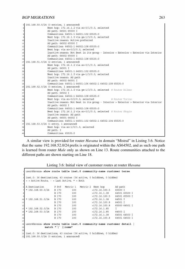
BGP MIGRATIONS 263
5 192.168.50.0/24 (3 entries, 1 announced)6 Next hop: 172.16.1.2 via so-0/1/0.0, selected7 AS path: 64501 65500 I8 Communities: 64501:1 64501:102 65535:09 Next hop: 172.16.1.5 via ge-1/3/0.0, selected
10 Inactive reason: Active preferred11 AS path: 64502 65500 I12 Communities: 64502:1 64502:108 65535:013 Next hop: via so-0/2/0.0, selected14 Inactive reason: Not Best in its group - Interior > Exterior > Exterior via Interior15 AS path: 64502 65500 I16 Communities: 64502:1 64502:108 65535:017 192.168.51.0/24 (2 entries, 1 announced)18 Next hop: 172.16.1.2 via so-0/1/0.0, selected19 AS path: 64501 I20 Communities: 64501:1 64501:102 65535:021 Next hop: 172.16.1.5 via ge-1/3/0.0, selected22 Inactive reason: AS path23 AS path: 64502 64501 I24 Communities: 64501:1 64501:106 64502:1 64502:108 65535:025 192.168.52.0/24 (3 entries, 1 announced)26 Next hop: 172.16.1.5 via ge-1/3/0.0, selected # Router Bilbao27 AS path: 64502 I28 Communities: 64502:1 64502:108 65535:029 Next hop: via so-0/2/0.0, selected # Router Torino30 Inactive reason: Not Best in its group - Interior > Exterior > Exterior via Interior31 AS path: 64502 I32 Communities: 64502:1 64502:108 65535:033 Next hop: 172.16.1.2 via so-0/1/0.0, selected # Router Skopie34 Inactive reason: AS path35 AS path: 64501 64502 I36 Communities: 64501:1 64501:102 64502:1 64502:104 65535:037 192.168.53.0/24 (1 entry, 1 announced)38 Next hop: via so-1/0/1.0, selected39 AS path: I40 Communities: 65535:0
A similar view is provided for router Havana in domain “Mistral” in Listing 3.6. Noticethat the same 192.168.52.0/24 prefix is originated within the AS64502, and as such one pathis learned from router Male only as shown on Line 13. Route communities attached to thedifferent paths are shown starting on Line 18.
Listing 3.6: Initial view of customer routes at router Havana
1 user@Havana> show route table inet.0 community-name customer terse2
3 inet.0: 36 destinations, 43 routes (36 active, 0 holddown, 0 hidden)4 + = Active Route, - = Last Active, * = Both5
6 A Destination P Prf Metric 1 Metric 2 Next hop AS path7 * 192.168.50.0/24 B 170 100 >172.16.100.5 65500 I8 B 170 100 >172.16.1.38 64501 65500 I9 B 170 100 >172.16.100.5 64501 65500 I
10 * 192.168.51.0/24 B 170 100 >172.16.1.38 64501 I11 B 170 100 >172.16.100.8 64501 I12 B 170 100 >172.16.100.8 65500 64501 I13 * 192.168.52.0/24 B 170 100 >172.16.1.85 I14 * 192.168.53.0/24 B 170 100 >172.16.1.85 64503 I15 B 170 100 >172.16.1.38 64501 64503 I16 B 170 100 >172.16.100.8 64501 64503 I17
18 user@Havana> show route table inet.0 community-name customer detail |19 match " ˆ [ ˆ ]|comm"20
21 inet.0: 36 destinations, 43 routes (36 active, 0 holddown, 0 hidden)22 192.168.50.0/24 (3 entries, 1 announced)

264 NETWORK MERGERS AND MIGRATIONS
23 Communities: 65535:024 Communities: 64501:1 64501:106 65535:025 Communities: 64501:1 64501:1106 65535:026 192.168.51.0/24 (3 entries, 1 announced)27 Communities: 64501:1 64501:106 65535:028 Communities: 64501:1 64501:1106 65535:029 Communities: 65535:030 192.168.52.0/24 (1 entry, 1 announced)31 Communities: 65535:032 192.168.53.0/24 (3 entries, 1 announced)33 Communities: 64503:1 64503:101 65535:034 Communities: 64501:1 64501:106 64503:1 64503:101 65535:035 Communities: 64501:1 64501:1106 64503:1 64503:101 65535:0
The view within domain “Cyclone” is shown for router Livorno in Listing 3.7. Line 22 andLine 25 show two paths for the prefix 192.168.52.0/24, one over a direct leased line (WAN)connection, and another over the shared media with the upcoming NOC router. Notice thatthe prefix for the NOC pool 192.168.50.0/24 is also present.
Listing 3.7: Initial view of customer routes at router Livorno
1 user@Livorno> show route table inet.0 community-name customer detail |2 match " ˆ [ ˆ ]|Communities|AS path|reason|Proto|via"3
4 inet.0: 38 destinations, 47 routes (37 active, 0 holddown, 1 hidden)5 192.168.50.0/24 (3 entries, 1 announced)6 Next hop: 172.16.100.5 via fe-0/3/0.0, selected7 AS path: 65500 I8 Communities: 65535:09 Next hop: 172.16.1.37 via so-0/0/1.0, selected
10 Inactive reason: AS path11 AS path: 64502 65500 I12 Communities: 64502:1 64502:104 65535:013 Next hop: 172.16.100.5 via fe-0/3/0.0, selected14 Inactive reason: Not Best in its group - Update source15 AS path: 64502 65500 I16 Communities: 64502:1 64502:1104 65535:017 192.168.51.0/24 (1 entry, 1 announced)18 Next hop: 172.16.1.53 via ge-0/2/0.0 weight 0x1, selected19 AS path: I20 Communities: 65535:021 192.168.52.0/24 (3 entries, 1 announced)22 Next hop: 172.16.1.37 via so-0/0/1.0, selected23 AS path: 64502 I24 Communities: 64502:1 64502:104 65535:025 Next hop: 172.16.100.1 via fe-0/3/0.0, selected26 Inactive reason: Not Best in its group - Update source27 AS path: 64502 I28 Communities: 64502:1 64502:1104 65535:029 Next hop: 172.16.100.1 via fe-0/3/0.0, selected30 Inactive reason: AS path31 AS path: 65500 64502 I32 Communities: 64502:1 64502:1104 65535:033 192.168.53.0/24 (4 entries, 1 announced)34 Next hop: via so-0/0/0.0 weight 0x1, selected35 AS path: 64503 I36 Communities: 64503:1 64503:101 65535:037 Next hop: 172.16.1.37 via so-0/0/1.0, selected38 Inactive reason: AS path39 AS path: 64502 64503 I40 Communities: 64502:1 64502:104 64503:1 64503:101 65535:041 Next hop: 172.16.100.1 via fe-0/3/0.0, selected42 Inactive reason: Not Best in its group - Update source43 AS path: 64502 64503 I44 Communities: 64502:1 64502:1104 64503:1 64503:101 65535:045 Next hop: 172.16.100.1 via fe-0/3/0.0, selected

BGP MIGRATIONS 265
46 Inactive reason: AS path47 AS path: 65500 64502 64503 I48 Communities: 64502:1 64502:1104 64503:1 64503:101 65535:0
3.6.2 Target network
The dependence on the parallel IGP migration to a unified and common IS–IS topologyblocks a direct full-mesh integration. Therefore, the approach taken is to merge two of theASs in a confederation first, to later integrate all three domains into a full-mesh IBGP.
First milestone: Build confederation AS65550
The goal of the first phase in the migration is to transition the two independent ASs in domain“Cyclone” and domain “Mistral” into a single confederation. Figure 3.11 shows the targetnetwork scenario after reaching the first milestone. The independent AS64501 and AS64502are merged into a confederation.
AS65550IBGP ConfederationSub−AS 65002 Sub−AS 65001
AS 65500
AS64503
192.168.52.0/24 192.168.51.0/24
192.168.53.0/24
IBGP route reflection
domain "Mistral"
IBGP full mesh
domain "Cyclone"
IBGP full mesh
domain "Monsoon"
NOC192.168.50.0/24
Figure 3.11: Network state after first milestone with BGP confederation.
Second milestone: Full-mesh IBGP
Migration at the IGP layer is progressing smoothly to integrate all domains into a unifiedIS–IS topology. After the first milestone of the IGP migration is achieved, as described inthe IGP case study in Section 2.3.9, all routers have full visibility of the loopback addresseswithin the domain.
Business requirements impose a global merge into a single 4-byte AS65550 by transition-ing the confederation to a full IBGP mesh. The second phase in the BGP migration is to moveto a full-mesh IBGP topology, only after IS–IS reachability between all routers in the threedomains is accomplished, as shown in Figure 3.12.

266 NETWORK MERGERS AND MIGRATIONS
AS65550IBGP full mesh
192.168.52.0/24 192.168.51.0/24
192.168.53.0/24
domain "Mistral" domain "Cyclone"
domain "Monsoon"
NOC192.168.50.0/24
Figure 3.12: Final state after migration to full-mesh IBGP.
3.6.3 Migration strategy
The stages for the BGP migration strategy and their dependencies are illustrated inFigure 3.13. Note that some stages can be carried out in parallel while others such asconfederating member sub-ASs require strict sequencing.
Threeseparate
AutonomousSystems
Building a confederation
AS Transition
Full mesh IBGP
1. Confederation of Domain Cyclone
2. Confederation of Domain Mistral
1st
milest.
AS65550Confederation
with two sub−AS
Done!
2nd m.
AS65550Full IBGP
Mesh
Global IS−IS integration
3. first interconnectof both confederations
4. Monitor
10. Monitor
5. Roll out andcleanup
6. EBGPPeering
7. Prepare Lille
as route reflector8. Activatereflector
9. Switch firstpilot router tonew AS 11. Roll out
and clean up
Figure 3.13: Approach taken for the BGP migration.

BGP MIGRATIONS 267
The activities to carry out to achieve the migration follow:
• Build a confederation out of AS64501 and AS64502;
– In stage one, domain “Cyclone” is confederated into a single AS65550 with onlyone sub-AS 65001. Despite being confederated, all external peerings continue touse the original AS 64501 for peering.
– In stage two, domain “Mistral” is also confederated into the same AS65550with only one sub-AS 65002. External peerings follow the original AS 64502.Notice that not doing so and having AS65550 in the AS_PATH would trip ASloop detection mechanisms. Prefixes would be filtered between the two domains,which is undesirable.
– After this preparatory work, stage three establishes the first confederationinterconnect between domain “Mistral” and domain “Cyclone.” The secondpeering session over the LAN between router Havana and router Livorno isleft on the original ASs to simulate an incremental transition involving multipleinterconnects.
– Stage four monitors the transient state of both networks, which are confederatedinto a single AS65550 and at the same time separated into two ASs.
– Once migration issues are addressed, stage five undertakes the rollout to theremaining routers in both domains, followed by cleanup of interim configuration.
• Present the confederation prefixes as belonging to AS65550 to external peers;
– Previous work did not modify how external ASs view both domains, other thanbecause of changes in AS_PATH length. Stage six modifies how other ASsview the customers’ prefixes within domain “Mistral” and domain “Cyclone”by peering on the 4-byte AS 65550. Customer prefixes in these two domains areadvertised as originating from AS65550.
• Full-mesh IBGP of the IBGP confederation AS 65550 with full-mesh AS 65503 andthe NOC. The ultimate goal is to become a single AS. After the IS–IS migrationdescribed in the case study of Chapter 2, the staged approach taken to incorporatedomain “Monsoon” and building a BGP full mesh follows:
– Preparatory work is performed in stage seven. The NOC router Lille is preparedas a route reflector for AS 65550, albeit with an inactive (bgp cluster)reflection configuration. One reflector group is configured for each of the ASsor sub-ASs to be merged. All routers are configured with a new IBGP group,which eventually becomes the final configuration. Configured policies ensurethat the reflected routing information is not considered “best.” The evaluationof the reflected information should confirm that best-path selection is appropriate(based on the IGP cost).
– At stage eight, reflection is activated for router Lille, which becomes a relay forthe prefixes received from within the domain.
– At stage nine, the first router is transitioned to the new AS65550. Router Nantesis taken as a representative router for the change.
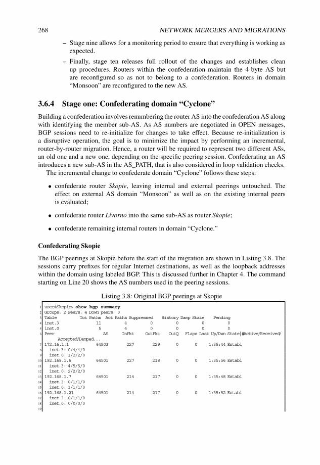
268 NETWORK MERGERS AND MIGRATIONS
– Stage nine allows for a monitoring period to ensure that everything is working asexpected.
– Finally, stage ten releases full rollout of the changes and establishes cleanup procedures. Routers within the confederation maintain the 4-byte AS butare reconfigured so as not to belong to a confederation. Routers in domain“Monsoon” are reconfigured to the new AS.
3.6.4 Stage one: Confederating domain “Cyclone”
Building a confederation involves renumbering the router AS into the confederation AS alongwith identifying the member sub-AS. As AS numbers are negotiated in OPEN messages,BGP sessions need to re-initialize for changes to take effect. Because re-initialization isa disruptive operation, the goal is to minimize the impact by performing an incremental,router-by-router migration. Hence, a router will be required to represent two different ASs,an old one and a new one, depending on the specific peering session. Confederating an ASintroduces a new sub-AS in the AS_PATH, that is also considered in loop validation checks.
The incremental change to confederate domain “Cyclone” follows these steps:
• confederate router Skopie, leaving internal and external peerings untouched. Theeffect on external AS domain “Monsoon” as well as on the existing internal peersis evaluated;
• confederate router Livorno into the same sub-AS as router Skopie;
• confederate remaining internal routers in domain “Cyclone.”
Confederating Skopie
The BGP peerings at Skopie before the start of the migration are shown in Listing 3.8. Thesessions carry prefixes for regular Internet destinations, as well as the loopback addresseswithin the domain using labeled BGP. This is discussed further in Chapter 4. The commandstarting on Line 20 shows the AS numbers used in the peering sessions.
Listing 3.8: Original BGP peerings at Skopie
1 user@Skopie> show bgp summary2 Groups: 2 Peers: 4 Down peers: 03 Table Tot Paths Act Paths Suppressed History Damp State Pending4 inet.3 11 4 0 0 0 05 inet.0 5 4 0 0 0 06 Peer AS InPkt OutPkt OutQ Flaps Last Up/Dwn State|#Active/Received/
Accepted/Damped...7 172.16.1.1 64503 227 229 0 0 1:35:44 Establ8 inet.3: 0/4/4/09 inet.0: 1/2/2/0
10 192.168.1.6 64501 227 218 0 0 1:35:56 Establ11 inet.3: 4/5/5/012 inet.0: 2/2/2/013 192.168.1.7 64501 214 217 0 0 1:35:48 Establ14 inet.3: 0/1/1/015 inet.0: 1/1/1/016 192.168.1.21 64501 214 217 0 0 1:35:52 Establ17 inet.3: 0/1/1/018 inet.0: 0/0/0/019

BGP MIGRATIONS 269
20 user@Skopie> show bgp neighbor | match ˆPeer21 Peer: 172.16.1.1+179 AS 64503 Local: 172.16.1.2+61782 AS 6450122 Peer: 192.168.1.6+179 AS 64501 Local: 192.168.1.2+58608 AS 6450123 Peer: 192.168.1.7+179 AS 64501 Local: 192.168.1.2+53273 AS 6450124 Peer: 192.168.1.21+179 AS 64501 Local: 192.168.1.2+53061 AS 64501
Listing 3.9 shows the existing configuration at router Skopie. Additional configuration tobecome a member of a confederation starts at Line 4, by setting up the sub-AS number andthe list of confederation members along with the confederation AS.
Notice on Line 22 that the local-as command is applied to the global level affecting allBGP groups to ensure at this preparatory stage that no change occurs to the internal orexternal peering by activating this configuration.
Listing 3.9: Activating the confederation
1 user@Skopie> show configuration routing-options autonomous-system2 64501;3
4 user@Skopie# set routing-options autonomous-system 650015 user@Skopie# set routing-options confederation 65550 members [ 65000 65001 65002 65003 ]6
7 user@Skopie# show routing-options | find autonomous8 autonomous-system 65001;9 confederation 65550 members [ 65001 65002 ];
10
11 user@Skopie# set protocols bgp local-as 64501 alias12 user@Skopie> show configuration protocols bgp13 family inet {14 unicast;15 labeled-unicast {16 rib {17 inet.3;18 }19 }20 }21 export [ nhs own-loopback ];22 local-as 64501 alias; # Maintain peerings on original AS6450123 group IBGP-Mesh {24 type internal;25 local-address 192.168.1.2;26 export [ nhs own-loopback ];27 neighbor 192.168.1.6;28 neighbor 192.168.1.21;29 neighbor 192.168.1.7;30 }31 group EBGP {32 export [ tag-64501 tag-skopie customer-routes own-loopback ];33 neighbor 172.16.1.1 {34 peer-as 64503;35 }36 inactive: neighbor 172.16.100.99 {37 peer-as 64502;38 }39 }
Committing these changes in the configuration involves a BGP session flap. All peeringsreconfigure to the new settings, using the confederation sub-AS (65001) for the internalpeerings, and the confederation AS (65550) for the external peering. This is shown inListing 3.10. Note that both the local and remote ASs show no indication of a TCP transportport as shown starting at Line 12, hinting that the peerings are down.

270 NETWORK MERGERS AND MIGRATIONS
Listing 3.10: Reconfigured sessions after confederation settings
1 user@Skopie> show bgp summary2 Groups: 2 Peers: 4 Down peers: 43 Table Tot Paths Act Paths Suppressed History Damp State Pending4 inet.3 0 0 0 0 0 05 inet.0 0 0 0 0 0 06 Peer AS InPkt OutPkt OutQ Flaps Last Up/Dwn State|#Active/Received/
Accepted/Damped...7 172.16.1.1 64503 0 0 0 0 2 Active8 192.168.1.6 65001 0 0 0 0 2 Active9 192.168.1.7 65001 0 0 0 0 2 Active
10 192.168.1.21 65001 0 0 0 0 2 Active11
12 user@Skopie> show bgp neighbor | match ˆPeer13 Peer: 172.16.1.1 AS 64503 Local: 172.16.1.2 AS 6555014 Peer: 192.168.1.6 AS 65001 Local: 192.168.1.2 AS 6500115 Peer: 192.168.1.7 AS 65001 Local: 192.168.1.2 AS 6500116 Peer: 192.168.1.21 AS 65001 Local: 192.168.1.2 AS 65001
With the above settings, the peers reject session establishment because of incorrect ASnumbers. This rejection trips the local-as logic to switch to the original AS number, 64501.A sample exchange is shown in Listing 3.11.
Listing 3.11: Sample AS negotiation in IBGP with alias
1 Jun 29 06:03:20.260834 bgp_send: sending 59 bytes to 192.168.1.21 (Internal AS 65001)2 Jun 29 06:03:20.2608703 Jun 29 06:03:20.260870 BGP SEND 192.168.1.2+59769 -> 192.168.1.21+1794 Jun 29 06:03:20.260918 BGP SEND message type 1 (Open) length 595 Jun 29 06:03:20.260955 BGP SEND version 4 as 65001 holdtime 90 id 192.168.1.2 parmlen 306 Jun 29 06:03:20.260985 BGP SEND MP capability AFI=1, SAFI=17 Jun 29 06:03:20.261013 BGP SEND Refresh capability, code=1288 Jun 29 06:03:20.261040 BGP SEND Refresh capability, code=29 Jun 29 06:03:20.261071 BGP SEND Restart capability, code=64, time=120, flags=
10 Jun 29 06:03:20.261102 BGP SEND 4 Byte AS-Path capability (65), as_num 6500111 Jun 29 06:03:20.26230312 Jun 29 06:03:20.262303 BGP RECV 192.168.1.21+179 -> 192.168.1.2+5976913 Jun 29 06:03:20.262379 BGP RECV message type 1 (Open) length 5914 Jun 29 06:03:20.262416 BGP RECV version 4 as 64501 holdtime 90 id 192.168.1.21 parmlen 3015 Jun 29 06:03:20.262446 BGP RECV MP capability AFI=1, SAFI=116 Jun 29 06:03:20.262473 BGP RECV Refresh capability, code=12817 Jun 29 06:03:20.262500 BGP RECV Refresh capability, code=218 Jun 29 06:03:20.262531 BGP RECV Restart capability, code=64, time=120, flags=19 Jun 29 06:03:20.262562 BGP RECV 4 Byte AS-Path capability (65), as_num 6450120 Jun 29 06:03:20.26268321 Jun 29 06:03:20.262683 BGP RECV 192.168.1.21+179 -> 192.168.1.2+5976922 Jun 29 06:03:20.262747 BGP RECV message type 3 (Notification) length 2123 Jun 29 06:03:20.262780 BGP RECV Notification code 2 (Open Message Error)24 subcode 2 (bad peer AS number)25 <...>26 Jun 29 06:03:36.31731827 Jun 29 06:03:36.317318 BGP RECV 192.168.1.21+51147 -> 192.168.1.2+17928 Jun 29 06:03:36.317588 BGP RECV message type 1 (Open) length 5929 Jun 29 06:03:36.317627 BGP RECV version 4 as 64501 holdtime 90 id 192.168.1.21 parmlen 3030 Jun 29 06:03:36.317658 BGP RECV MP capability AFI=1, SAFI=131 Jun 29 06:03:36.317686 BGP RECV Refresh capability, code=12832 Jun 29 06:03:36.317712 BGP RECV Refresh capability, code=233 Jun 29 06:03:36.317744 BGP RECV Restart capability, code=64, time=120, flags=34 Jun 29 06:03:36.317774 BGP RECV 4 Byte AS-Path capability (65), as_num 6450135 Jun 29 06:03:36.317995 advertising receiving-speaker only capability to neighbor 192.168.1.21 (
Internal AS 65001)36 Jun 29 06:03:36.318040 bgp_send: sending 59 bytes to 192.168.1.21 (Internal AS 65001)37 Jun 29 06:03:36.31807438 Jun 29 06:03:36.318074 BGP SEND 192.168.1.2+179 -> 192.168.1.21+5114739 Jun 29 06:03:36.318192 BGP SEND message type 1 (Open) length 5940 Jun 29 06:03:36.318233 BGP SEND version 4 as 64501 holdtime 90 id 192.168.1.2 parmlen 30

BGP MIGRATIONS 271
41 Jun 29 06:03:36.318262 BGP SEND MP capability AFI=1, SAFI=142 Jun 29 06:03:36.318290 BGP SEND Refresh capability, code=12843 Jun 29 06:03:36.318317 BGP SEND Refresh capability, code=244 Jun 29 06:03:36.318347 BGP SEND Restart capability, code=64, time=120, flags=45 Jun 29 06:03:36.318378 BGP SEND 4 Byte AS-Path capability (65), as_num 6450146 Jun 29 06:03:36.318932
Listing 3.12 shows the result after AS negotiation, with peering ASs listed starting atLine 19. This time the ports bound to the IP addresses indicate a properly established TCPsession.
Listing 3.12: Result on router Skopie after AS negotiation
1 user@Skopie> show bgp summary2 Groups: 2 Peers: 4 Down peers: 03 Table Tot Paths Act Paths Suppressed History Damp State Pending4 inet.3 11 4 0 0 0 05 inet.0 6 4 0 0 0 06 Peer AS InPkt OutPkt OutQ Flaps Last Up/Dwn State|#Active/Received/
Accepted/Damped...7 172.16.1.1 64503 15 18 0 0 33 Establ8 inet.3: 0/4/4/09 inet.0: 1/3/3/0
10 192.168.1.6 64501 14 8 0 0 1:37 Establ11 inet.3: 4/5/5/012 inet.0: 2/2/2/013 192.168.1.7 64501 8 7 0 0 1:37 Establ14 inet.3: 0/1/1/015 inet.0: 1/1/1/016 192.168.1.21 64501 6 6 0 0 1:37 Establ17 inet.3: 0/1/1/018
19 user@Skopie> show bgp neighbor | match ˆPeer20 Peer: 172.16.1.1+179 AS 64503 Local: 172.16.1.2+51633 AS 6450121 Peer: 192.168.1.6+62149 AS 64501 Local: 192.168.1.2+179 AS 6450122 Peer: 192.168.1.7+64096 AS 64501 Local: 192.168.1.2+179 AS 6450123 Peer: 192.168.1.21+64771 AS 64501 Local: 192.168.1.2+179 AS 64501
Because the peering AS negotiated during the OPEN message exchange decides thecontents of the AS_PATH in updates, and the peering AS did not change, the routinginformation still matches the situation at the start of this stage.
A sample output from router Livorno and router Nantes reflects this, as shown inListing 3.13.
Listing 3.13: Routing view in router Nantes and router Livorno after confederating skopie
1 user@Nantes> show route table inet.0 community-name customer terse2
3 inet.0: 40 destinations, 47 routes (40 active, 0 holddown, 0 hidden)4 + = Active Route, - = Last Active, * = Both5
6 A Destination P Prf Metric 1 Metric 2 Next hop AS path7 * 192.168.50.0/24 B 170 100 >172.16.1.5 64502 65500 I8 B 170 100 >so-0/2/0.0 64502 65500 I9 B 170 100 >172.16.1.2 64501 65500 I
10 * 192.168.51.0/24 B 170 100 >172.16.1.2 64501 I11 B 170 100 >172.16.1.5 64502 64501 I12 * 192.168.52.0/24 B 170 100 >172.16.1.5 64502 I13 B 170 100 >so-0/2/0.0 64502 I14 B 170 100 >172.16.1.2 64501 64502 I15 * 192.168.53.0/24 B 170 100 >so-1/0/1.0 I16
17 user@Livorno> show route table inet.0 community-name customer terse18

272 NETWORK MERGERS AND MIGRATIONS
19 inet.0: 39 destinations, 48 routes (38 active, 0 holddown, 1 hidden)20 + = Active Route, - = Last Active, * = Both21
22 A Destination P Prf Metric 1 Metric 2 Next hop AS path23 * 192.168.50.0/24 B 170 100 >172.16.100.5 65500 I24 B 170 100 >172.16.1.37 64502 65500 I25 B 170 100 >172.16.100.5 64502 65500 I26 * 192.168.51.0/24 B 170 100 >172.16.1.53 I27 * 192.168.52.0/24 B 170 100 >172.16.1.37 64502 I28 B 170 100 >172.16.100.1 64502 I29 B 170 100 >172.16.100.1 65500 64502 I30 * 192.168.53.0/24 B 170 100 >so-0/0/0.0 64503 I31 B 170 100 >172.16.1.37 64502 64503 I32 B 170 100 >172.16.100.1 64502 64503 I33 B 170 100 >172.16.100.1 65500 64502 64503 I
Confederating Livorno
The same configuration added on router Skopie in Listing 3.9 is also implemented on routerLivorno. The AS negotiation stage agrees to use the global AS, 64501, for the peeringsto external neighbors as well as for the peerings to the internal neighbors that are not yetmigrated.
After committing the preliminary configuration, the BGP peerings flap, as shown inListing 3.14. Initially, all peers are assumed to be on the confederation sub-AS for internalpeerings and global AS for external peerings, as shown on Line 14.
Listing 3.14: Peerings flap at router Livorno after confederating
1 user@Livorno> show bgp summary2 Groups: 4 Peers: 6 Down peers: 63 Table Tot Paths Act Paths Suppressed History Damp State Pending4 inet.0 0 0 0 0 0 05 inet.3 0 0 0 0 0 06 Peer AS InPkt OutPkt OutQ Flaps Last Up/Dwn State|#Active/Received/
Accepted/Damped...7 172.16.1.37 64502 0 0 0 0 7 Active8 172.16.100.1 64502 0 0 0 0 7 Active9 172.16.100.5 65500 0 0 0 0 7 Active
10 192.168.1.2 65550 0 0 0 0 7 Active11 192.168.1.7 65550 0 0 0 0 7 Active12 192.168.1.21 65550 0 0 0 0 7 Active13
14 user@Livorno> show bgp neighbor | match ˆPeer15 Peer: 172.16.1.37 AS 64502 Local: 172.16.1.38 AS 6555016 Peer: 172.16.100.1 AS 64502 Local: 172.16.100.8 AS 6555017 Peer: 172.16.100.5 AS 65500 Local: 172.16.100.8 AS 6555018 Peer: 192.168.1.2 AS 65001 Local: 192.168.1.6 AS 6500119 Peer: 192.168.1.7 AS 65001 Local: 192.168.1.6 AS 6500120 Peer: 192.168.1.21 AS 65001 Local: 192.168.1.6 AS 65001
The result of AS negotiation is shown in Listing 3.15. Two AS numbers are used forIBGP peering: the old global AS, for non-migrated peers, and the new confederation sub-AS(65001) towards router Skopie (Line 5).
Listing 3.15: New peerings at router Livorno after confederating
1 user@Livorno> show bgp neighbor | match ˆPeer2 Peer: 172.16.1.37+62508 AS 64502 Local: 172.16.1.38+179 AS 645013 Peer: 172.16.100.1+64757 AS 64502 Local: 172.16.100.8+179 AS 645014 Peer: 172.16.100.5+58576 AS 65500 Local: 172.16.100.8+179 AS 645015 Peer: 192.168.1.2+179 AS 64501 Local: 192.168.1.6+51045 AS 65001 # IBGP Peering on sub-AS

BGP MIGRATIONS 273
6 Peer: 192.168.1.7+50246 AS 64501 Local: 192.168.1.6+179 AS 64501 # Still on old AS7 Peer: 192.168.1.21+58473 AS 64501 Local: 192.168.1.6+179 AS 64501 # Still on old AS
Confederating internal peers
In the same fashion, the remainder of routers in AS64501 in domain “Cyclone” areprogressively confederated into sub-AS 65001, one router at a time.
What If... Keeping internal peers on the old AS
If the AS migration is considered to be a transitional effort, it might not require changingall internal routers. Taking router Honolulu as an example of an internal router, there is norequirement to confederate it to the new AS. Advertisement over internal peerings do notcare about the locally configured AS, so ensuring establishment of the session (by keepinglocal-as at the peers) suffices. A similar approach could be taken for router Male in domain“Mistral”.
For ISPs with a few external connections on a couple of border routers, AS renumberingmay be as simple as modifying just these border routers!
3.6.5 Stage two: Confederating domain “Mistral”
The strategy for the domain “Mistral” is a replica of the one taken for domain “Cyclone,” thistime for sub-AS 65002. At this stage, care has to be taken to ensure that router Havana androuter Livorno peer only on the original AS numbers, and to avoid a sub-AS confederationBGP peering until both domains have properly migrated all border routers with externalpeerings.
Configuration changes to confederate domain “Mistral”
Listing 3.16 summarizes the changes in domain “Mistral”. The configuration for routerBilbao mimics the one of router Skopie, mapped to the new sub-AS. Note that router Malehas no alias configuration, because it is assumed that all internal peering connections to thealready confederated border routers are made with the new subconfederation AS number. Asan alternative, router Male could keep the original AS number and stick to the alias settingto connect to the border routers, or it could modify its own AS number but keep the knob tomaintain service to additional internal border routers.
Listing 3.16: Changes to confederate AS 64502
1 # Bilbao, similar to Skopie2 user@Bilbao# set routing-options autonomous-system 65002;3 user@Bilbao# set routing-options confederation 65550 members [ 65001 65002 ]4 user@Bilbao# set protocols bgp local-as 64502 alias5
6 # Male, similar to Honolulu and Barcelona7 user@Male# set routing-options autonomous-system 65002;8 user@Male# set routing-options confederation 65550 members [ 65001 65002 ]9
10 # Havana, similar to Livorno11 user@Havana# set routing-options autonomous-system 65002;12 user@Havana# set routing-options confederation 65550 members [ 65001 65002 ]13 user@Havana# set protocols bgp local-as 64502 alias

274 NETWORK MERGERS AND MIGRATIONS
The configuration for router Havana in Listing 3.16 mimics the one from router Livorno.However, because both ends of the peering session have alias configured (Line 13),additional configuration shown in Listing 3.17 is necessary to cover a corner case in whichalias negotiation never succeeds.
Listing 3.17: Changes to confederate AS64502
1 [ edit protocols bgp group EBGP ]2 user@Havana# set neighbor 172.16.1.38 local-as 64502 no-prepend-global-as3 user@Havana# set neighbor 172.16.100.8 local-as 64502 no-prepend-global-as
What If... AS selection when both sides use alias
The alias knob alternates the local AS value between the router AS and the configuredlocal-as. When both ends of the session implement this behavior, as is done by the neighboron Line 19 of Listing 3.21, there may be a condition where the two sides get stuck at theglobal AS number, as shown in Listing 3.18. Both sides attempt to establish a session,but fail to switch ASs as they both bring down the TCP connection before receiving thenotification with the bad peer-as number information, as shown on Line 29 and Line 56.
Having a BGP peer behave as a passive side (thus never initiating the TCP session) doesnot help because alias requires the OPEN message exchange to start on the local sidefor the AS to switch.
Listing 3.18: Stuck alias negotiation
1 # Havana to Livorno2 Jun 30 05:21:30.712125 bgp_send: sending 59 bytes to 172.16.100.8 (External AS 64501)3 Jun 30 05:21:30.7121624 Jun 30 05:21:30.712162 BGP SEND 172.16.100.1+64956 -> 172.16.100.8+1795 Jun 30 05:21:30.712209 BGP SEND message type 1 (Open) length 596 Jun 30 05:21:30.712246 BGP SEND version 4 as 23456 holdtime 90 id 192.168.1.4 parmlen 307 Jun 30 05:21:30.712313 BGP SEND MP capability AFI=1, SAFI=18 Jun 30 05:21:30.712343 BGP SEND Refresh capability, code=1289 Jun 30 05:21:30.712370 BGP SEND Refresh capability, code=2
10 Jun 30 05:21:30.712401 BGP SEND Restart capability, code=64, time=120, flags=11 Jun 30 05:21:30.712431 BGP SEND 4 Byte AS-Path capability (65), as_num 6555012 Jun 30 05:21:30.71451413 Jun 30 05:21:30.714514 BGP RECV 172.16.100.8+179 -> 172.16.100.1+6495614 Jun 30 05:21:30.714588 BGP RECV message type 1 (Open) length 5915 Jun 30 05:21:30.714622 BGP RECV version 4 as 23456 holdtime 90 id 192.168.1.6 parmlen 3016 Jun 30 05:21:30.714689 BGP RECV MP capability AFI=1, SAFI=117 Jun 30 05:21:30.714717 BGP RECV Refresh capability, code=12818 Jun 30 05:21:30.714743 BGP RECV Refresh capability, code=219 Jun 30 05:21:30.714774 BGP RECV Restart capability, code=64, time=120, flags=20 Jun 30 05:21:30.714804 BGP RECV 4 Byte AS-Path capability (65), as_num 6555021 Jun 30 05:21:30.714960 bgp_process_open:2587: NOTIFICATION sent to 172.16.100.8 (External AS 64501):22 code 2 (Open Message Error)23 subcode 2 (bad peer AS number),24 Reason: peer 172.16.100.8 (External AS 64501) claims 65550, 64501 configured25 Jun 30 05:21:30.715070 bgp_send: sending 21 bytes to 172.16.100.8 (External AS 64501)26 Jun 30 05:21:30.71510727 Jun 30 05:21:30.715107 BGP SEND 172.16.100.1+64956 -> 172.16.100.8+17928 Jun 30 05:21:30.715155 BGP SEND message type 3 (Notification) length 2129 Jun 30 05:21:30.715186 BGP SEND Notification code 2 (Open Message Error)30 subcode 2 (bad peer AS number)31
32 # Livorno to Havana33 Jun 30 05:21:30.71345434 Jun 30 05:21:30.713454 BGP RECV 172.16.100.1+64956 -> 172.16.100.8+17935 Jun 30 05:21:30.713581 BGP RECV message type 1 (Open) length 59

BGP MIGRATIONS 275
36 Jun 30 05:21:30.713604 BGP RECV version 4 as 23456 holdtime 90 id 192.168.1.4 parmlen 3037 Jun 30 05:21:30.713623 BGP RECV MP capability AFI=1, SAFI=138 Jun 30 05:21:30.713640 BGP RECV Refresh capability, code=12839 Jun 30 05:21:30.713656 BGP RECV Refresh capability, code=240 Jun 30 05:21:30.713675 BGP RECV Restart capability, code=64, time=120, flags=41 Jun 30 05:21:30.713730 BGP RECV 4 Byte AS-Path capability (65), as_num 6555042 Jun 30 05:21:30.713795 advertising receiving-speaker only capability43 to neighbor 172.16.100.1 (External AS 64502)44 Jun 30 05:21:30.71382445 Jun 30 05:21:30.713824 BGP SEND 172.16.100.8+179 -> 172.16.100.1+6495646 Jun 30 05:21:30.713852 BGP SEND message type 1 (Open) length 5947 Jun 30 05:21:30.713873 BGP SEND version 4 as 23456 holdtime 90 id 192.168.1.6 parmlen 3048 Jun 30 05:21:30.713890 BGP SEND MP capability AFI=1, SAFI=149 Jun 30 05:21:30.713907 BGP SEND Refresh capability, code=12850 Jun 30 05:21:30.713922 BGP SEND Refresh capability, code=251 Jun 30 05:21:30.713940 BGP SEND Restart capability, code=64, time=120, flags=52 Jun 30 05:21:30.713958 BGP SEND 4 Byte AS-Path capability (65), as_num 6555053 Jun 30 05:21:30.71397754 Jun 30 05:21:30.713977 BGP SEND 172.16.100.8+179 -> 172.16.100.1+6495655 Jun 30 05:21:30.714003 BGP SEND message type 3 (Notification) length 2156 Jun 30 05:21:30.714022 BGP SEND Notification code 2 (Open Message Error)57 subcode 2 (bad peer AS number)58 Jun 30 05:21:30.714128 bgp_pp_recv:2860: NOTIFICATION sent to 172.16.100.1+64956 (proto):59 code 2 (Open Message Error)60 subcode 2 (bad peer AS number),61 Reason: no group for 172.16.100.1+64956 (proto)62 from AS 65550 found (peer as mismatch), dropping him
If the timing is right, such that one of the peers has already switched on the alias AS, thepeering is brought up correctly. One possible way to avoid this race condition is to forceone of the sides to always use the local-as (with the no-prepend- global-as option)instead of bouncing back and forth between the two ASs.
The configuration change is shown in Listing 3.19, where router Livorno has theadditional flag on Line 4. Traces for router Havana starting on Line 10 show the resultingbringup.
Listing 3.19: Use of no-prepend-global-as to counter negotiation deadlock
1 user@Livorno# show protocols bgp group EBGP neighbor 172.16.100.12 export [ tag-64501 tag-Livorno-Lan customer-routes own-loopback ];3 peer-as 64502;4 local-as 64501 no-prepend-global-as; # Stick to this AS5
6 user@Havana# show protocols bgp group EBGP neighbor 172.16.100.87 export [ tag-64502 tag-havana-lan customer-routes ];8 peer-as 64501;9
10
11 Jun 30 05:53:01.966119 BGP RECV 172.16.100.8+57819 -> 172.16.100.1+17912 Jun 30 05:53:01.966241 BGP RECV message type 1 (Open) length 5913 Jun 30 05:53:01.966286 BGP RECV version 4 as 64501 holdtime 90 id 192.168.1.6 parmlen 3014 Jun 30 05:53:01.966317 BGP RECV MP capability AFI=1, SAFI=115 Jun 30 05:53:01.966344 BGP RECV Refresh capability, code=12816 Jun 30 05:53:01.966371 BGP RECV Refresh capability, code=217 Jun 30 05:53:01.966402 BGP RECV Restart capability, code=64, time=120, flags=18 Jun 30 05:53:01.966432 BGP RECV 4 Byte AS-Path capability (65), as_num 6450119 Jun 30 05:53:01.966678 advertising receiving-speaker only capability20 to neighbor 172.16.100.8 (External AS 64501)21 Jun 30 05:53:01.966723 bgp_send: sending 59 bytes to 172.16.100.8 (External AS 64501)22 Jun 30 05:53:01.96675723 Jun 30 05:53:01.966757 BGP SEND 172.16.100.1+179 -> 172.16.100.8+5781924 Jun 30 05:53:01.966803 BGP SEND message type 1 (Open) length 5925 Jun 30 05:53:01.966838 BGP SEND version 4 as 23456 holdtime 90 id 192.168.1.4 parmlen 3026 Jun 30 05:53:01.966866 BGP SEND MP capability AFI=1, SAFI=127 Jun 30 05:53:01.966893 BGP SEND Refresh capability, code=128

276 NETWORK MERGERS AND MIGRATIONS
28 Jun 30 05:53:01.966920 BGP SEND Refresh capability, code=229 Jun 30 05:53:01.966948 BGP SEND Restart capability, code=64, time=120, flags=30 Jun 30 05:53:01.966978 BGP SEND 4 Byte AS-Path capability (65), as_num 6555031 Jun 30 05:53:01.96873332 Jun 30 05:53:01.968733 BGP RECV 172.16.100.8+57819 -> 172.16.100.1+17933 Jun 30 05:53:01.968811 BGP RECV message type 3 (Notification) length 2134 Jun 30 05:53:01.968843 BGP RECV Notification code 2 (Open Message Error)35 subcode 2 (bad peer AS number)36 Jun 30 05:53:33.97199737 Jun 30 05:53:33.971997 BGP RECV 172.16.100.8+49936 -> 172.16.100.1+17938 Jun 30 05:53:33.972162 BGP RECV message type 1 (Open) length 5939 Jun 30 05:53:33.972200 BGP RECV version 4 as 64501 holdtime 90 id 192.168.1.6 parmlen 3040 Jun 30 05:53:33.972230 BGP RECV MP capability AFI=1, SAFI=141 Jun 30 05:53:33.972258 BGP RECV Refresh capability, code=12842 Jun 30 05:53:33.972284 BGP RECV Refresh capability, code=243 Jun 30 05:53:33.972315 BGP RECV Restart capability, code=64, time=120, flags=44 Jun 30 05:53:33.972346 BGP RECV 4 Byte AS-Path capability (65), as_num 6450145 Jun 30 05:53:33.972595 advertising receiving-speaker only capability46 to neighbor 172.16.100.8 (External AS 64501)47 Jun 30 05:53:33.972639 bgp_send: sending 59 bytes to 172.16.100.8 (External AS 64501)48 Jun 30 05:53:33.97267449 Jun 30 05:53:33.972674 BGP SEND 172.16.100.1+179 -> 172.16.100.8+4993650 Jun 30 05:53:33.972721 BGP SEND message type 1 (Open) length 5951 Jun 30 05:53:33.972755 BGP SEND version 4 as 64502 holdtime 90 id 192.168.1.4 parmlen 3052 Jun 30 05:53:33.972783 BGP SEND MP capability AFI=1, SAFI=153 Jun 30 05:53:33.972810 BGP SEND Refresh capability, code=12854 Jun 30 05:53:33.972837 BGP SEND Refresh capability, code=255 Jun 30 05:53:33.972866 BGP SEND Restart capability, code=64, time=120, flags=56 Jun 30 05:53:33.972906 BGP SEND 4 Byte AS-Path capability (65), as_num 64502
IBGP activation inside domain “Mistral”
Because the session between router Havana and router Male is an IBGP one, the AS_PATHis not modified in the exchanged advertisements. Hence, there is no net effect to the routinginformation other than to the loop-detection mechanisms for received updates, which nowinclude the confederation AS and member sub-ASs. Listing 3.20 shows no change in therouting view for router Male, despite the anomalous peering arrangement.
Listing 3.20: Routing views after confederating router Havana
1 user@male-re0> show bgp neighbor | match ˆPeer2 Peer: 192.168.1.4+179 AS 65002 Local: 192.168.1.20+61582 AS 650023 Peer: 192.168.1.8+179 AS 65002 Local: 192.168.1.20+51381 AS 650024
5 user@male-re0> show route table inet.0 community-name customer detail |6 match " ˆ [ ˆ ]|comm|AS path|reason|via"7
8 inet.0: 12 destinations, 12 routes (12 active, 0 holddown, 0 hidden)9 192.168.50.0/24 (1 entry, 1 announced)
10 Next hop: 172.16.1.86 via ge-4/2/4.0, selected11 AS path: 65500 I12 Communities: 65535:013 192.168.51.0/24 (1 entry, 1 announced)14 Next hop: 172.16.1.86 via ge-4/2/4.0, selected15 AS path: 64501 I16 Communities: 64501:1 64501:106 65535:017 192.168.52.0/24 (1 entry, 1 announced)18 AS path: I19 Communities: 65535:020 192.168.53.0/24 (1 entry, 1 announced)21 Next hop: via so-3/2/1.0, selected22 AS path: 64503 I23 Communities: 64503:1 64503:101 65535:0

BGP MIGRATIONS 277
3.6.6 Stage three: First confederation peering to bind both sub-ASdomains together
After all the border routers are confederated in each domain, the two independent ASs with aconfederation sub-AS each can be merged into a single confederation AS with two sub-ASs.This part of the transition has to be a coordinated operation on both ends of the confederationborder. The existing peering between router Livorno and router Havana is modified into aconfederation peering by configuring both sides of the peering session simultaneously.
Listing 3.21 shows the changes on both ends of the peering between router Livorno androuter Havana. The neighbor on Line 15 is deactivated, and a new group is added for theconfederation peering on Line 27. The second session between the two ASs on Line 19 ismaintained to illustrate a transitional stage in which sessions use both types of arrangement,EBGP and CBGP.
Listing 3.21: Bringing up the confederation BGP external peering
1 user@Livorno# show protocols bgp2 <...>3 local-as 64501 alias;4 group IBGP {5 type internal;6 local-address 192.168.1.6;7 export [ nhs own-loopback ];8 neighbor 192.168.1.2;9 neighbor 192.168.1.7;
10 neighbor 192.168.1.21;11 }12 group EBGP {13 type external;14 export own-loopback;15 inactive: neighbor 172.16.1.37 {16 export [ tag-64501 tag-Livorno customer-routes own-loopback ];17 peer-as 64502;18 }19 neighbor 172.16.100.1 {20 export [ tag-64501 tag-Livorno-Lan customer-routes own-loopback ];21 peer-as 64502;22 }23 neighbor 172.16.100.5 {24 peer-as 65500;25 }26 }27 group EBGP-Confed {28 type external;29 export [ nhs tag-64501 tag-Livorno customer-routes own-loopback ];30 neighbor 172.16.1.37 {31 peer-as 65002;32 }33 }
The confederation peering rationale assumes an intra-organizational setup, in which bothorganizations have full visibility. By default, the protocol mechanics do not change the nexthop in updates egressing a confederation border. Given that, at this stage, visibility is limitedbecause both domains are still independent at the IGP layer, a next-hop self policy is addedin Line 29 to allow for proper route resolution.
Committing the changes in Listing 3.21 brings up the confederation peering on the sub-AS numbers, as shown on Line 3 of Listing 3.22. Note that the parallel session on Line 4 isstill using the old AS numbers.

278 NETWORK MERGERS AND MIGRATIONS
Listing 3.22: External confederation peering
1 user@Livorno> show bgp neighbor | match ˆPeer2
3 Peer: 172.16.1.37+52323 AS 65002 Local: 172.16.1.38+179 AS 650014 Peer: 172.16.100.1+179 AS 64502 Local: 172.16.100.8+63329 AS 645015 Peer: 172.16.100.5+58798 AS 65500 Local: 172.16.100.8+179 AS 645016 Peer: 192.168.1.2+56608 AS 64501 Local: 192.168.1.6+179 AS 650017 Peer: 192.168.1.7+52918 AS 64501 Local: 192.168.1.6+179 AS 645018 Peer: 192.168.1.21+58262 AS 64501 Local: 192.168.1.6+179 AS 64501
3.6.7 Stage four: Monitoring period
A cautionary period is defined to monitor this interim stage where some of the peerings areon the original AS using EBGP and one peering is already CBGP.
Prefixes originated in two ASs
Having two ASs that interconnect sessions with both old and new arrangements simulta-neously may be the case when confederation peerings are brought up incrementally in thenetwork and both ASs has multiple peering routers. During the transition, routing informationhas two different origins. The advertisements in Listing 3.23 show this dichotomy for thenow internal customer prefix from sub-AS 65002 on router Livorno. For instance, lookingat the customer prefix from domain “Mistral,” 192.168.52.0/24 has a path with the sub-AS(Line 12), and the paths learned from the original external AS (direct on Line 13 and throughrouter Lille on Line 14).
Listing 3.23: Prefixes with duplicate origins
1 user@Livorno> show route table inet.0 community-name customer terse2
3 inet.0: 38 destinations, 48 routes (37 active, 0 holddown, 2 hidden)4 + = Active Route, - = Last Active, * = Both5
6 A Destination P Prf Metric 1 Metric 2 Next hop AS path7 * 192.168.50.0/24 B 170 100 >172.16.100.5 65500 I8 B 170 100 >172.16.1.37 (65002) 65500 I9 B 170 100 >172.16.100.5 64502 65500 I
10 * 192.168.51.0/24 B 170 100 >172.16.1.53 I11 B 170 100 >172.16.100.1 64502 I12 * 192.168.52.0/24 B 170 100 >172.16.1.37 (65002) I13 B 170 100 >172.16.100.1 64502 I14 B 170 100 >172.16.100.1 65500 64502 I15 * 192.168.53.0/24 B 170 100 >172.16.1.37 (65002) 64503 I16 B 170 100 >so-0/0/0.0 64503 I17 B 170 100 >172.16.100.1 64502 64503 I18 B 170 100 >172.16.100.1 65500 64502 64503 I
Routing loop analysis
Analysis of Listing 3.23 on Line 11 shows the customer route 192.168.51/24 belonging todomain “Cyclone” as originated by domain “Mistral”. This route is originated in domain“Cyclone” and advertised to domain “Mistral” over the new confederated session, asshown in Figure 3.14. The advertisement includes the confederation sub-AS, 65001, and theinformation about the old AS, AS64501, is lost. Domain “Mistral” considers this prefix as

BGP MIGRATIONS 279
originated within its own global AS65550, and sends this route back over the pre-existingEBGP session. Because it is an external peering, router Havana removes the confederationsub-AS information and prepends its own AS, AS64502, in the update to router Livorno.
HavanaLivorno
192.168.1.4192.168.1.6
IBGP route reflection
domain "Mistral"
AS64502 and
AS65550 / sub−AS 65002
IBGP full mesh
domain "Cyclone"
AS64501 and
AS65550 / sub−AS 65001
Customer prefix
192.168.51.0/24CBGP
Prefix: 192.168.51.0/24
AS_PATH: (65001)
Prefix: 192.168.51.0/24
AS_PATH: 64502
EBGP
1
2
Figure 3.14: Routing loop for prefix 192.168.51.0/24 during transition.
Having both types of peering (confederated and non-confederated) introduces a potentialrouting loop and the default protection against using this route is the AS_PATH length rule(a prefix is better if it has a shorter AS_PATH). The experienced reader may already raise hisor her eyebrows at the risk this valid path is introducing.
Care has to be taken to compensate for the lack of natural AS loop protection. Giventhat all advertisements are tagged with the originating AS, border routes can match on thiscommunity as a protection mechanism. Prefix filtering can also be implemented in caseswhere the community attribute is filtered by a transit BGP peer. The additional configurationpolicy in Listing 3.24 gives an example of this approach. A community from64501 is taggedto all prefixes traversing domain “Cyclone” and an import policy blocks updates with thiscommunity.
Listing 3.24: Blocking self advertisements to compensate for the lack of AS loop detection
1 [edit]2 user@Livorno# show policy-options policy-statement tag-645013 from protocol bgp;4 then {5 community add from64501;6 }7 [edit]8 user@Livorno# show configuration policy-options policy-statement block-own9 term community-based {
10 from community from64501;11 then reject;12 }13 term prefix-based {14 from {15 route-filter 192.168.51.0/24 orlonger;16 }17 then reject;18 }19
20 [edit]

280 NETWORK MERGERS AND MIGRATIONS
21 user@Livorno# show protocols bgp | compare22 [edit protocols bgp group EBGP]23 + import block-own;24 [edit protocols bgp group EBGP-Confed]25 + import block-own;
However, implementing this change might eliminate more than just the customer prefixesif a third-party AS is receiving transit service. Looking at the prefix from domain “Monsoon,”192.168.53.0/24, and comparing Listing 3.23, Line 17 and Listing 3.25, Line 10, the missingpath for prefix 192.168.53/24 can be explained as seen in Listing 3.25, Line 13, which showsthat router Livorno tagged this update when advertising it to router Havana (Line 38).
Listing 3.25: Blocking looped third-party updates
1 user@Livorno# run show route table inet.0 terse 192.168.53.0/242
3 inet.0: 38 destinations, 45 routes (37 active, 0 holddown, 5 hidden)4 + = Active Route, - = Last Active, * = Both5
6 A Destination P Prf Metric 1 Metric 2 Next hop AS path7 * 192.168.51.0/24 B 170 100 >172.16.1.53 I8 * 192.168.52.0/24 B 170 100 >172.16.1.37 (65002) I9 B 170 100 >172.16.100.1 64502 I
10 * 192.168.53.0/24 B 170 100 >so-0/0/0.0 64503 I11
12 user@Livorno# run show route table inet.0 community-name customer all 192.168.53.0/2413 detail | match " ˆ [ ˆ ]|state|BGP|AS path|commu"14
15 inet.0: 37 destinations, 46 routes (36 active, 0 holddown, 5 hidden)16 192.168.53.0/24 (3 entries, 1 announced)17 *BGP Preference: 170/-10118 Label-switched-path Livorno-to-Skopie19 State: <Active Int Ext>20 Local AS: 65001 Peer AS: 6450121 Task: BGP_65001.192.168.1.2+5660822 Announcement bits (3): 0-KRT 4-BGP RT Background 5-Resolve tree 223 AS path: 64503 I24 Communities: 64503:1 64503:101 65535:025 BGP /-10126 State: <Hidden Ext>27 Inactive reason: Unusable path # Hidden route because of policy28 Local AS: 65001 Peer AS: 6450229 Task: BGP_64502.172.16.100.1+17930 AS path: 64502 64503 I31 Communities: 64501:1 64501:106 64502:1 64502:1104 64503:1 64503:101 65535:032 BGP33 State: <Hidden Int Ext>34 Inactive reason: Unusable path # Hidden route because of AS loop35 Local AS: 65001 Peer AS: 6500236 Task: BGP_65002.172.16.1.37+5232337 AS path: (65002 65001) 64503 I (Looped: 65001)38 Communities: 64501:1 64501:106 64502:1 64502:104 64503:1 64503:101 65535:0
Hidden routes for labeled paths
Changing from single-hop EBGP to CBGP activates the route resolution process. No next-hop resolution is necessary in single-hop EBGP because a local connection exists. For CBGPand IBGP, the next-hop can be far away.
In regular IPv4 prefixes, BGP next-hop resolution occurs on the inet.3 RIB first, then oninet.0. For labeled paths, like VPN-IPv4 and Labeled-IPv4, resolution occurs using inet.3only. Even though the CBGP session peers on the interface address, the resolution processlooks at inet.3 for the appropriate next hop. This concept is discussed further in Section 4.4.4.

BGP MIGRATIONS 281
The paths received from the CBGP session in router Livorno shown on Listing 3.26indicate that the IPv4 paths are correctly received and installed while Labeled-IPv4 pathsremain hidden (Line 11).
Listing 3.26: Change from EBGP to CBGP hides routes in inet.3
1 user@Livorno> show route receive-protocol bgp 172.16.1.372
3 inet.0: 36 destinations, 42 routes (35 active, 0 holddown, 3 hidden)4 Prefix Nexthop MED Lclpref AS path5 * 192.168.52.0/24 192.168.1.20 100 (65002) I6 * 192.168.53.0/24 192.168.1.8 100 (65002) 64503 I7
8 inet.3: 7 destinations, 16 routes (6 active, 0 holddown, 7 hidden) # Hidden routes in inet.39
10
11 user@Livorno> show route receive-protocol bgp 172.16.1.37 hidden12
13 inet.0: 36 destinations, 42 routes (35 active, 0 holddown, 3 hidden)14 Prefix Nexthop MED Lclpref AS path15 192.168.51.0/24 192.168.1.7 100 (65002 65001) I16
17 inet.3: 7 destinations, 16 routes (6 active, 0 holddown, 7 hidden)18 Prefix Nexthop MED Lclpref AS path19 192.168.1.2/32 172.16.1.37 100 (65002) 64502 64501 I20 192.168.1.6/32 172.16.1.37 100 (65002) 64502 64501 I21 192.168.1.7/32 172.16.1.37 100 (65002) 64502 64501 I22 192.168.1.8/32 192.168.1.8 100 (65002) I # No next hop23 192.168.1.20/32 192.168.1.20 100 (65002) I # No next hop24 192.168.1.21/32 172.16.1.37 100 (65002) 64502 64501 I
To activate these labeled paths it is required to perform an additional configuration step asdescribed in the Junos Tip on Section 4.5.4.
Listing 3.27 shows the configuration to leak the interface in inet.3 using RIB groups alongwith the corrected view.
Listing 3.27: Leak interface in inet.3 to allow resolution
1 user@Livorno# show | compare2 [edit policy-options policy-statement interface-to-inet3]3 term loopback { ... }4 + term cbgp {5 + from interface so-0/0/1.0;6 + then accept;7 + }8 term no-more-inet3 { ... }9
10 user@Livorno# show routing-options rib-groups int-to-inet311 import-rib [ inet.0 inet.3 ];12 import-policy interface-to-inet3;13
14 user@Livorno> show route receive-protocol bgp 172.16.1.3715
16 inet.0: 36 destinations, 42 routes (35 active, 0 holddown, 3 hidden)17 Prefix Nexthop MED Lclpref AS path18 * 192.168.52.0/24 172.16.1.37 100 (65002) I19 * 192.168.53.0/24 172.16.1.37 100 (65002) 64503 I20
21 inet.3: 9 destinations, 18 routes (8 active, 0 holddown, 5 hidden)22 Prefix Nexthop MED Lclpref AS path23 * 192.168.1.4/32 172.16.1.37 100 (65002) I24 * 192.168.1.8/32 172.16.1.37 100 (65002) I25 * 192.168.1.20/32 172.16.1.37 100 (65002) I
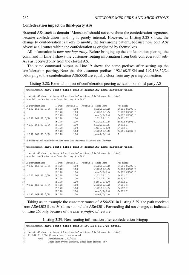
282 NETWORK MERGERS AND MIGRATIONS
Confederation impact on third-party ASs
External ASs such as domain “Monsoon” should not care about the confederation segments,because confederation handling is purely internal. However, as Listing 3.28 shows, thechange to confederation is likely to modify the forwarding pattern, because now both ASsadvertise all routes within the confederation as originated by themselves.
All information is now one hop away. Before bringing up the confederation peering, thecommand in Line 1 shows the customer-routing information from both confederation sub-ASs as received only from the closest AS.
The same command output in Line 19 shows the same prefixes after setting up theconfederation peering. Note that the customer prefixes 192.168.51/24 and 192.168.52/24belonging to the confederation AS65550 are equally close from any peering connection.
Listing 3.28: External impact of confederation peering activation on third-party AS
1 user@Nantes> show route table inet.0 community-name customer terse2
3 inet.0: 40 destinations, 47 routes (40 active, 0 holddown, 0 hidden)4 + = Active Route, - = Last Active, * = Both5
6 A Destination P Prf Metric 1 Metric 2 Next hop AS path7 * 192.168.50.0/24 B 170 100 >172.16.1.2 64501 65500 I8 B 170 100 >172.16.1.5 64502 65500 I9 B 170 100 >so-0/2/0.0 64502 65500 I
10 * 192.168.51.0/24 B 170 100 >172.16.1.2 64501 I11 B 170 100 >172.16.1.5 64502 64501 I12 * 192.168.52.0/24 B 170 100 >172.16.1.5 64502 I13 B 170 100 >so-0/2/0.0 64502 I14 B 170 100 >172.16.1.2 64501 64502 I15 * 192.168.53.0/24 B 170 100 >so-1/0/1.0 I16
17 # bringup of confederation session between Livorno and Havana18
19 user@Nantes> show route table inet.0 community-name customer terse20
21 inet.0: 40 destinations, 48 routes (40 active, 0 holddown, 0 hidden)22 + = Active Route, - = Last Active, * = Both23
24 A Destination P Prf Metric 1 Metric 2 Next hop AS path25 * 192.168.50.0/24 B 170 100 >172.16.1.2 64501 65500 I26 B 170 100 >172.16.1.5 64502 65500 I27 B 170 100 >so-0/2/0.0 64502 65500 I28 * 192.168.51.0/24 B 170 100 >172.16.1.2 64501 I29 B 170 100 >172.16.1.5 64502 I30 B 170 100 >so-0/2/0.0 64502 I31 * 192.168.52.0/24 B 170 100 >172.16.1.2 64501 I32 B 170 100 >172.16.1.5 64502 I33 B 170 100 >so-0/2/0.0 64502 I34 * 192.168.53.0/24 B 170 100 >so-1/0/1.0 I
Taking as an example the customer routes of AS64501 in Listing 3.29, the path receivedfrom AS64502 (Line 30) does not include AS64501. Forwarding did not change, as indicatedon Line 26, only because of the active preferred feature.
Listing 3.29: New routing information after confederation bringup
1 user@Nantes> show route table inet.0 192.168.51.0/24 detail2
3 inet.0: 40 destinations, 48 routes (40 active, 0 holddown, 0 hidden)4 192.168.51.0/24 (3 entries, 1 announced)5 *BGP Preference: 170/-1016 Next hop type: Router, Next hop index: 567

BGP MIGRATIONS 283
7 Next-hop reference count: 88 Source: 172.16.1.29 Next hop: 172.16.1.2 via so-0/1/0.0, selected
10 State: <Active Ext>11 Local AS: 64503 Peer AS: 6450112 Age: 5:35:5013 Task: BGP_64501.172.16.1.2+5163314 Announcement bits (3): 0-KRT 4-BGP RT Background 5-Resolve tree 115 AS path: 64501 I16 Communities: 64501:1 64501:102 65535:017 Accepted18 Localpref: 10019 Router ID: 192.168.1.220 BGP Preference: 170/-10121 Next hop type: Router, Next hop index: 57422 Next-hop reference count: 723 Source: 172.16.1.524 Next hop: 172.16.1.5 via ge-1/3/0.0, selected25 State: <Ext>26 Inactive reason: Active preferred27 Local AS: 64503 Peer AS: 6450228 Age: 1:0129 Task: BGP_64502.172.16.1.5+17930 AS path: 64502 I # AS Path does not include 6450131 Communities: 64501:1 64501:106 64502:1 64502:108 65535:032 Accepted33 Localpref: 10034 Router ID: 192.168.1.835 BGP Preference: 170/-10136 Next hop type: Indirect37 Next-hop reference count: 338 Source: 192.168.1.339 Next hop type: Router, Next hop index: 56440 Next hop: via so-0/2/0.0, selected41 Protocol next hop: 192.168.1.342 Indirect next hop: 8c930a8 -43 State: <NotBest Int Ext>44 Inactive reason: Not Best in its group - Interior > Exterior > Exterior via Interior45 Local AS: 64503 Peer AS: 6450346 Age: 1:01 Metric2: 16047 Task: BGP_64503.192.168.1.3+6436448 AS path: 64502 I49 Communities: 64501:1 64501:106 64502:1 64502:108 65535:050 Accepted51 Localpref: 10052 Router ID: 10.10.1.3
The analysis of external AS shows that traffic may change for prefixes belonging toconfederation members. This change is also expected whenever an AS peers in multiplelocations with another AS and is not specific to confederations.
Junos Tip: Detecting a leak of confederation segments
In Junos OS, the EBGP session strips confederation segments only if the router isconfigured as a confederation member.
If the confederation peering between sub-AS 65001 and sub-AS 65002 is establishedbefore all border routers are confederated, leaking of the AS_CONFED elements inthe AS_PATH occurs. This leak can be detected easily on the receiving peer, becausethe offending route flags the route as hidden and unusable and contains the invalidconfederation member in the AS_PATH.
Listing 3.30 is the route view on router Nantes when router Bilbao is not yet configuredas a confederation member, but when the peering between router Livorno and router

284 NETWORK MERGERS AND MIGRATIONS
Havana is a confederation BGP session. The AS_PATH information of the updatefrom router Bilbao for customers in domain “Cyclone” (192.168.51.0/24) includes theconfederation AS 65001, which is unexpected on an external peering session. Line 16reports this fact.
Listing 3.30: Illegal confederation segment received over EBGP
1 user@Nantes> show route hidden table inet.0 detail2
3 inet.0: 43 destinations, 49 routes (43 active, 0 holddown, 1 hidden)4 <...>5 192.168.51.0/24 (2 entries, 1 announced)6 BGP7 Next hop type: Router, Next hop index: 5638 Next-hop reference count: 69 Source: 172.16.1.5
10 Next hop: 172.16.1.5 via ge-1/3/0.0, selected11 State: <Hidden Ext>12 Inactive reason: Unusable path13 Local AS: 64503 Peer AS: 6450214 Age: 2:0715 Task: BGP_64502.172.16.1.5+17916 AS path: 64502 (65001) I (InvalidConfedSegment)17 Communities: 64501:1 64501:106 64502:1 64502:108 65535:018 Router ID: 192.168.1.8
3.6.8 Stage five: CBGP deployment and EBGP cleanup betweendomain “Cyclone” and domain “Mistral”
General rollout and subsequent cleanup of legacy configuration is carried out in this stage.
General deployment of CBGP
Interesting effects showed up during the monitoring stage. Once clarified, general rolloutof remaining CBGP peerings can take place in a coordinated fashion. Routing changes canbe handled using BGP attributes to prioritize some routes over others, which is a commonoperation in the internetworking industry.
Cleanup of EBGP
After domain “Cyclone” and domain “Mistral” have been confederated and when all theconfederation peerings are up, there is no further need to keep the original AS for internalpeerings. An example is shown in Listing 3.31. Line 1 shows the confederation peerings atrouter Livorno over the internal AS65001.
Because alias is active for IBGP, the peering between router Skopie and router Livornoshown in Line 5 and Line 15 illustrates diverse AS settings based on how the AS negotiationtakes place.
Listing 3.31: IBGP peering on confederation AS
1 user@Skopie# run show bgp neighbor | match ˆPeer2 Peer: 172.16.1.37+51276 AS 65002 Local: 172.16.1.38+179 AS 650013 Peer: 172.16.100.1+179 AS 65002 Local: 172.16.100.8+65414 AS 650014 Peer: 172.16.100.5+58798 AS 65500 Local: 172.16.100.8+179 AS 64501

BGP MIGRATIONS 285
5 Peer: 192.168.1.2+179 AS 64501 Local: 192.168.1.6+54176 AS 65001 # Real-AS6 Peer: 192.168.1.7+60913 AS 65001 Local: 192.168.1.6+179 AS 650017 Peer: 192.168.1.21+179 AS 65001 Local: 192.168.1.6+55362 AS 650018
9 # peering flaps, router restart10
11 user@Livorno> show bgp neighbor | match ˆPeer12 Peer: 172.16.1.37+179 AS 65002 Local: 172.16.1.38+60039 AS 6500113 Peer: 172.16.100.1+179 AS 65002 Local: 172.16.100.8+59415 AS 6500114 Peer: 172.16.100.5+64620 AS 65500 Local: 172.16.100.8+179 AS 6450115 Peer: 192.168.1.2+62535 AS 65001 Local: 192.168.1.6+179 AS 65001 # Sub-AS16 Peer: 192.168.1.7+62835 AS 65001 Local: 192.168.1.6+179 AS 6500117 Peer: 192.168.1.21+179 AS 65001 Local: 192.168.1.6+55843 AS 65001
The alias command can be removed for IBGP, but it has to stay active for externalpeerings, discussed in Section 3.6.9. Configuration changes are shown in Listing 3.32. Noticethat the removal of the alias knob is not disruptive, as revealed by the Last Up/Downcolumn starting at Line 8.
Listing 3.32: Keep alias command for EBGP
1 [edit]2 user@Skopie# show | compare3 [edit protocols bgp]4 - local-as 64501 alias;5 [edit protocols bgp group EBGP]6 + local-as 64501 alias;7
8 user@Skopie> show bgp summary9 Groups: 2 Peers: 4 Down peers: 0
10 Table Tot Paths Act Paths Suppressed History Damp State Pending11 inet.0 7 4 0 0 0 012 inet.3 11 4 0 0 0 013 Peer AS InPkt OutPkt OutQ Flaps Last Up/Dwn State|#Active/Received/
Accepted/Damped...14 172.16.1.1 64503 26 29 0 0 7:57 Establ15 inet.0: 1/3/3/016 inet.3: 3/4/4/017 192.168.1.6 65001 26 27 0 0 7:52 Establ18 inet.0: 2/3/3/019 inet.3: 1/5/5/020 192.168.1.7 65001 22 28 0 0 7:57 Establ21 inet.0: 1/1/1/022 inet.3: 0/1/1/023 192.168.1.21 65001 21 29 0 0 7:57 Establ24 inet.0: 0/0/0/025 inet.3: 0/1/1/0
3.6.9 Stage six: External peering on new 4-byte AS
At this point, the confederation has been successfully migrated. However, the external viewstill sees the old AS, awaiting customers, peers, and service providers to change their externalpeering configuration. The intuitive change at the external AS is the peer-as setting, but thechanges usually also involve tweaking policies related to the updates themselves, includingrouting policy and placing additional prefix rules in forwarding filters.
Use of domain “Monsoon” as transit
The goal when merging an AS is to consolidate different ASs into one. If the AS to mergeis receiving transit from a third party, this transit service breaks as soon as the AS_PATH

286 NETWORK MERGERS AND MIGRATIONS
includes the AS number of the consolidated AS. At the onset of the migration, domain“Mistral” and domain “Cyclone” can get transit service through router Nantes in domain“Monsoon.” As soon as the external peering uses the confederation AS 65550, transit breaksbecause of AS loop detection at router Skopie and router Bilbao. Mechanisms exist to allowleaking of such prefixes through the loops configuration construct, but this involves a changein the whole domain. After all, an AS should not require its confederation to be repairedthrough a transit AS!
Changing EBGP peering at domain “Monsoon”
Listing 3.33 is an example of a change in router Nantes as per configuration on Line 18 thattakes effect immediately by router Skopie and router Bilbao after AS negotiation occurs.
Listing 3.33: External AS border Nantes to peer to 4-byte confederation AS
1 user@Nantes> show bgp summary2 Groups: 2 Peers: 5 Down peers: 03 Table Tot Paths Act Paths Suppressed History Damp State Pending4 inet.3 9 8 0 0 0 05 inet.0 10 4 0 0 0 06 Peer AS InPkt OutPkt OutQ Flaps Last Up/Dwn State|#Active/Received/
Accepted/Damped...7 172.16.1.2 64501 1019 937 0 4 12:23 Establ8 inet.3: 4/5/5/09 inet.0: 1/3/3/0
10 172.16.1.5 64502 1370 1327 0 4 1:18:57 Establ11 inet.3: 4/4/4/012 inet.0: 2/3/3/013 192.168.1.3 64503 1811 1805 0 0 13:14:47 0/3/3/0
0/0/0/014 192.168.1.9 64503 1755 1807 0 0 13:15:26 0/0/0/0
0/0/0/015 192.168.1.10 64503 1759 1808 0 0 13:15:39 1/1/1/0
0/0/0/016
17 [edit]18 user@Nantes# show | compare19 [edit protocols bgp group EBGP neighbor 172.16.1.5]20 - peer-as 64502;21 + peer-as 65550;22 [edit protocols bgp group EBGP neighbor 172.16.1.2]23 - peer-as 64501;24 + peer-as 65550;25
26 user@Nantes> show bgp summary27 Groups: 2 Peers: 5 Down peers: 028 Table Tot Paths Act Paths Suppressed History Damp State Pending29 inet.3 16 8 0 0 0 030 inet.0 10 4 0 0 0 031 Peer AS InPkt OutPkt OutQ Flaps Last Up/Dwn State|#Active/Received/
Accepted/Damped...32 172.16.1.2 65550 24 16 0 0 5:59 Establ33 inet.3: 4/8/8/034 inet.0: 0/3/3/035 172.16.1.5 65550 22 24 0 0 6:03 Establ36 inet.3: 4/8/8/037 inet.0: 3/3/3/038 192.168.1.3 64503 1829 1829 0 0 13:22:56 0/3/3/0
0/0/0/039 192.168.1.9 64503 1773 1830 0 0 13:23:35 0/0/0/0
0/0/0/040 192.168.1.10 64503 1777 1832 0 0 13:23:48 1/1/1/0
0/0/0/0
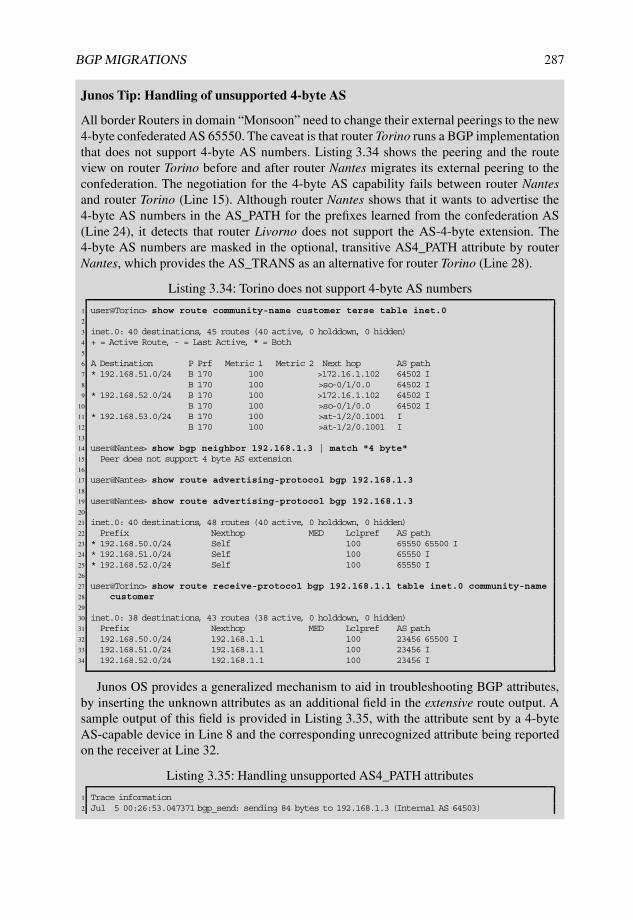
BGP MIGRATIONS 287
Junos Tip: Handling of unsupported 4-byte AS
All border Routers in domain “Monsoon” need to change their external peerings to the new4-byte confederated AS 65550. The caveat is that router Torino runs a BGP implementationthat does not support 4-byte AS numbers. Listing 3.34 shows the peering and the routeview on router Torino before and after router Nantes migrates its external peering to theconfederation. The negotiation for the 4-byte AS capability fails between router Nantesand router Torino (Line 15). Although router Nantes shows that it wants to advertise the4-byte AS numbers in the AS_PATH for the prefixes learned from the confederation AS(Line 24), it detects that router Livorno does not support the AS-4-byte extension. The4-byte AS numbers are masked in the optional, transitive AS4_PATH attribute by routerNantes, which provides the AS_TRANS as an alternative for router Torino (Line 28).
Listing 3.34: Torino does not support 4-byte AS numbers
1 user@Torino> show route community-name customer terse table inet.02
3 inet.0: 40 destinations, 45 routes (40 active, 0 holddown, 0 hidden)4 + = Active Route, - = Last Active, * = Both5
6 A Destination P Prf Metric 1 Metric 2 Next hop AS path7 * 192.168.51.0/24 B 170 100 >172.16.1.102 64502 I8 B 170 100 >so-0/1/0.0 64502 I9 * 192.168.52.0/24 B 170 100 >172.16.1.102 64502 I
10 B 170 100 >so-0/1/0.0 64502 I11 * 192.168.53.0/24 B 170 100 >at-1/2/0.1001 I12 B 170 100 >at-1/2/0.1001 I13
14 user@Nantes> show bgp neighbor 192.168.1.3 | match "4 byte"15 Peer does not support 4 byte AS extension16
17 user@Nantes> show route advertising-protocol bgp 192.168.1.318
19 user@Nantes> show route advertising-protocol bgp 192.168.1.320
21 inet.0: 40 destinations, 48 routes (40 active, 0 holddown, 0 hidden)22 Prefix Nexthop MED Lclpref AS path23 * 192.168.50.0/24 Self 100 65550 65500 I24 * 192.168.51.0/24 Self 100 65550 I25 * 192.168.52.0/24 Self 100 65550 I26
27 user@Torino> show route receive-protocol bgp 192.168.1.1 table inet.0 community-name28 customer29
30 inet.0: 38 destinations, 43 routes (38 active, 0 holddown, 0 hidden)31 Prefix Nexthop MED Lclpref AS path32 192.168.50.0/24 192.168.1.1 100 23456 65500 I33 192.168.51.0/24 192.168.1.1 100 23456 I34 192.168.52.0/24 192.168.1.1 100 23456 I
Junos OS provides a generalized mechanism to aid in troubleshooting BGP attributes,by inserting the unknown attributes as an additional field in the extensive route output. Asample output of this field is provided in Listing 3.35, with the attribute sent by a 4-byteAS-capable device in Line 8 and the corresponding unrecognized attribute being reportedon the receiver at Line 32.
Listing 3.35: Handling unsupported AS4_PATH attributes
1 Trace information2 Jul 5 00:26:53.047371 bgp_send: sending 84 bytes to 192.168.1.3 (Internal AS 64503)

288 NETWORK MERGERS AND MIGRATIONS
3 Jul 5 00:26:53.0474994 Jul 5 00:26:53.047499 BGP SEND 192.168.1.1+179 -> 192.168.1.3+633315 Jul 5 00:26:53.047562 BGP SEND message type 2 (Update) length 846 Jul 5 00:26:53.047599 BGP SEND flags 0x40 code Origin(1): IGP7 Jul 5 00:26:53.047638 BGP SEND flags 0x40 code ASPath(2) length 4: 234568 Jul 5 00:26:53.047673 BGP SEND flags 0xc0 code AS4Path(17) length 6: 65550 # AS4Path attribute9 Jul 5 00:26:53.047705 BGP SEND flags 0x40 code NextHop(3): 192.168.1.1
10 Jul 5 00:26:53.047736 BGP SEND flags 0x40 code LocalPref(5): 10011 Jul 5 00:26:53.047776 BGP SEND flags 0xc0 code Communities(8): 64501:1 64501:106 65535:012 Jul 5 00:26:53.047818 BGP SEND 192.168.51.0/2413
14 user@Torino> show route 192.168.51/24 detail inactive-path15
16 inet.0: 40 destinations, 45 routes (40 active, 0 holddown, 0 hidden)17 192.168.51.0/24 (2 entries, 1 announced)18 BGP Preference: 170/-10119 Next hop type: Indirect20 Next-hop reference count: 221 Source: 192.168.1.122 Next hop type: Router, Next hop index: 49123 Next hop: via so-0/1/0.0, selected24 Protocol next hop: 192.168.1.125 Indirect next hop: 8a73138 -26 State: <Int Ext>27 Inactive reason: Interior > Exterior > Exterior via Interior28 Local AS: 64503 Peer AS: 6450329 Age: 12:26 Metric2: 16030 Task: BGP_64503.192.168.1.1+17931 AS path: 23456 I Unrecognized Attributes: 9 bytes32 AS path: Attr flags e0 code 11: 02 01 00 01 00 0e # AS4Path attribute33 Communities: 64501:1 64501:106 64502:1 64502:108 65535:034 Localpref: 10035 Router ID: 10.10.1.1
In this case, the EBGP peering between router Torino and router Bilbao needs to stick tothe old AS, AS64502, a bit longer, until router Torino is upgraded to a release with 4-byteAS support.
With this last step, the first milestone has been accomplished. The network is confederatedand external peerings see the confederation as the 4-byte AS65550.
Meanwhile, the parallel link-state IGP migration is progressing successfully. Visibility ofall routers in the three domains is available through a unified and common IS–IS topology,which allows the second part of the migration towards an IBGP full mesh to start.
3.6.10 Stage seven: Bringup IBGP peerings to Lille
Listing 3.36 shows the initial BGP configuration required for router Lille to become a routereflector for all routers to be migrated. A generic group with the allow setting enablesany router with AS 65550 to peer with router Lille and to obtain all routing information.Groups with specific neighborship information are required to align the proper alias AS withthe sub-AS domain. One such group is defined for domain “Cyclone” (Line 29), domain“Mistral” (Line 39), and an additional group for the external domain “Monsoon” (Line 48).The existing group used for the transport of labeled BGP paths in the MPLS transport casestudy (Chapter 4) is left untouched, maintaining the alias knob for the AS 65500 (Line 13).
Notice at this stage that the configuration on router Lille does not act as a reflector (that is,the cluster statement is not active). This is done on purpose as a safety measure to controlwhich routing information is being received.

BGP MIGRATIONS 289
Listing 3.36: BGP setup for Lille
1 user@Lille# show protocols bgp2 family inet {3 unicast;4 labeled-unicast {5 rib {6 inet.3;7 }8 }9 }
10 group EBGP {11 local-address 172.16.100.5;12 export [ customer-routes from-loopback-to-LBGP ];13 local-as 65500 alias;14 neighbor 172.16.100.1 {15 peer-as 64502;16 }17 neighbor 172.16.100.8 {18 peer-as 64501;19 }20 }21 group IBGP-RR-Cluster {22 type internal;23 family inet {24 unicast;25 }26 inactive: cluster 192.168.1.5;27 allow 192.168.0.0/16;28 }29 group IBGPCluster-Cyclone {30 type internal;31 local-address 192.168.1.5;32 local-as 65001 alias;33 inactive: cluster 192.168.1.5;34 neighbor 192.168.1.2;35 neighbor 192.168.1.6;36 neighbor 192.168.1.7;37 neighbor 192.168.1.21;38 }39 group IBGPCluster-Mistral {40 type internal;41 local-address 192.168.1.5;42 local-as 65002 alias;43 inactive: cluster 192.168.1.5;44 neighbor 192.168.1.4;45 neighbor 192.168.1.20;46 neighbor 192.168.1.8;47 }48 group IBGPCluster-Monsoon {49 type internal;50 local-address 192.168.1.5;51 local-as 64503 alias;52 inactive: cluster 192.168.1.5;53 neighbor 192.168.1.1;54 neighbor 192.168.1.9;55 neighbor 192.168.1.10;56 neighbor 192.168.1.3;57 }58
59
60 user@Lille# show routing-options61 <...>62 router-id 192.168.1.5;63 autonomous-system 65550;
Each router to be migrated is configured with an additional BGP group, as the con-figuration template in Listing 3.37 shows. Note that for internal peering, each router uses

290 NETWORK MERGERS AND MIGRATIONS
the value configured under the autonomous system, which is the confederation sub-AS forconfederation members in domain “Mistral” and domain “Cyclone” and the domain AS fordomain “Monsoon.”
Listing 3.37: IBGP route reflector client template configuration
1 inactive: group IBGP-RRC {2 type internal;3 local-address 192.168.1.X; # Varies per router4 neighbor 192.168.1.5; # Lille5 }
Listing 3.38 illustrates the received customer prefixes from various border routers fromthe viewpoint of router Lille. The active paths correspond to the redistribution points of thecustomer infrastructure routes.
Listing 3.38: Lille as a regular IBGP router homed to all routers
1 user@Lille> show bgp summary | match " ˆ [ ˆ ]|inet.0"2
3 Groups: 4 Peers: 13 Down peers: 04 Table Tot Paths Act Paths Suppressed History Damp State Pending5 inet.0 21 3 0 0 0 06 inet.3 20 7 0 0 0 07 Peer AS InPkt OutPkt OutQ Flaps Last Up/Dwn State|#Active/Received/
Accepted/Damped...8 172.16.100.1 64502 121 120 0 0 47:26 Establ9 inet.0: 0/2/2/0
10 172.16.100.8 64501 124 127 0 0 47:22 Establ11 inet.0: 0/2/2/012 192.168.1.1 64503 71 66 0 0 28:36 Establ13 inet.0: 0/0/0/014 192.168.1.2 65001 68 67 0 0 27:36 Establ15 inet.0: 0/1/0/016 192.168.1.3 64503 38 30 0 0 13:27 Establ17 inet.0: 0/3/2/018 192.168.1.4 65002 84 78 0 0 31:26 Establ19 inet.0: 0/3/0/020 192.168.1.6 65001 92 78 0 1 31:41 Establ21 inet.0: 0/3/0/022 192.168.1.7 65001 80 83 0 0 33:28 Establ23 inet.0: 1/1/1/024 192.168.1.8 65002 79 75 0 0 32:01 Establ25 inet.0: 0/1/0/026 192.168.1.9 64503 57 57 0 0 24:40 Establ27 inet.0: 0/0/0/028 192.168.1.10 64503 70 74 0 1 18:01 Establ29 inet.0: 1/1/1/030 192.168.1.20 65002 103 84 0 0 33:59 Establ31 inet.0: 1/4/1/032 192.168.1.21 65001 52 50 0 0 22:31 Establ33 inet.0: 0/0/0/0
Most of the hidden routes are updates received over the pre-existing EBGP or CBGPpeerings that are propagated back to router Lille. Their AS_PATH hints at a loop, and so theyare hidden, as shown in Listing 3.39.
Listing 3.39: Hidden routes on Lille because of AS loop
1 user@Lille> show route table inet.0 community-name customer all terse2
3 inet.0: 34 destinations, 53 routes (34 active, 0 holddown, 12 hidden)

BGP MIGRATIONS 291
4 + = Active Route, - = Last Active, * = Both5
6 A Destination P Prf Metric 1 Metric 2 Next hop AS path7 * 192.168.50.0/24 S 5 Receive8 B >172.16.100.1 65500 I # Loop9 B >172.16.100.1 65500 I # Loop
10 B >172.16.100.8 65500 I # Loop11 B 172.16.100.1 64502 65500 I # Loop12 >172.16.100.813 * 192.168.51.0/24 B 170 100 >172.16.100.8 I14 B 170 100 >172.16.100.1 64502 I15 B 170 100 172.16.100.1 64502 I16 >172.16.100.817 B 170 100 >172.16.100.8 64501 I18 B >172.16.100.1 (65001) I19 B >172.16.100.1 (65001) I20 * 192.168.52.0/24 B 170 100 >172.16.100.1 I21 B 170 100 >172.16.100.1 64502 I22 B 170 100 172.16.100.1 64502 I23 >172.16.100.824 B 170 100 >172.16.100.8 64501 I25 B >172.16.100.8 (65002) I26 * 192.168.53.0/24 B 170 100 172.16.100.1 I27 >172.16.100.828 B >172.16.100.1 65500 I # Loop29 B >172.16.100.1 64503 I30 B >172.16.100.1 65500 I # Loop31 B >172.16.100.8 64503 I32 B >172.16.100.8 65500 I # Loop
Once router Lille peers with all routers, it can advertise its own address space as an internalroute. The view of this address space as seen by router Livorno is shown in Listing 3.40.Notice at Line 7 that the confederation AS is not counting towards the total AS_PATH length.
Listing 3.40: Selection after advertising the NOC space
1 user@Livorno> show route 192.168.50/24 detail | match " ˆ [ ˆ ]|AS|comm|reason|BGP"2
3 inet.0: 37 destinations, 49 routes (36 active, 0 holddown, 4 hidden)4 192.168.50.0/24 (4 entries, 1 announced)5 *BGP Preference: 170/-1016 Local AS: 65001 Peer AS: 650027 Task: BGP_65002.172.16.1.37+1798 Announcement bits (3): 0-KRT 4-BGP RT Background 5-Resolve tree 19 AS path: (65002) I
10 Communities: 64502:1 64502:104 65535:011 BGP Preference: 170/-10112 Inactive reason: Not Best in its group - Update source13 Local AS: 65001 Peer AS: 6500214 Task: BGP_65002.172.16.100.1+17915 AS path: (65002) I16 Communities: 64502:1 64502:104 65535:017 BGP Preference: 170/-10118 Inactive reason: Not Best in its group - Router ID19 Local AS: 65001 Peer AS: 6500120 Task: BGP_65001.192.168.1.5+17921 AS path: I22 Communities: 65535:023 BGP Preference: 170/-10124 Inactive reason: AS path25 Local AS: 65001 Peer AS: 6550026 Task: BGP_65500.172.16.100.5+6504227 AS path: 65500 I28 Communities: 65535:0

292 NETWORK MERGERS AND MIGRATIONS
3.6.11 Stage eight: Enable route reflection on router Lille
The updates from the NOC towards the routers are now directly reachable over the IGP.Updates from other routers are received at router Lille, but reflection needs to be activated torelay those updates, as shown in Listing 3.41.
Listing 3.41: Configuration of router Lille as a route reflector
1 user@Lille> show configuration | compare rollback 12 [edit protocols bgp group IBGP-RR-Cluster]3 ! active: cluster 192.168.1.5;4 [edit protocols bgp group IBGPCluster-Cyclone]5 ! active: cluster 192.168.1.5;6 [edit protocols bgp group IBGPCluster-Mistral]7 ! active: cluster 192.168.1.5;8 [edit protocols bgp group IBGPCluster-Monsoon]9 ! active: cluster 192.168.1.5;
Listing 3.42 shows the customer routes as learned by the NOC router Lille.
Listing 3.42: View on router Lille and border router Nantes
1 user@Lille> show route community-name customer terse2
3 inet.0: 34 destinations, 40 routes (34 active, 0 holddown, 4 hidden)4 + = Active Route, - = Last Active, * = Both5
6 A Destination P Prf Metric 1 Metric 2 Next hop AS path7 * 192.168.0.0/24 S 5 Receive8 * 192.168.51.0/24 B 170 100 >172.16.100.8 I9 * 192.168.52.0/24 B 170 100 >172.16.100.1 I
10 * 192.168.53.0/24 B 170 100 172.16.100.1 I11 >172.16.100.812 B 170 100 172.16.100.1 I13 >172.16.100.814
15 user@Lille> show route 192.168.48/21 terse16
17 inet.0: 34 destinations, 52 routes (34 active, 0 holddown, 11 hidden)18 + = Active Route, - = Last Active, * = Both19
20 A Destination P Prf Metric 1 Metric 2 Next hop AS path21 * 192.168.50.0/24 S 5 Receive22 * 192.168.51.0/24 B 170 100 >172.16.100.8 I23 B 170 100 >172.16.100.1 64502 I24 B 170 100 172.16.100.1 64502 I25 >172.16.100.826 B 170 100 >172.16.100.8 64501 I27 * 192.168.52.0/24 B 170 100 >172.16.100.1 I28 B 170 100 >172.16.100.1 64502 I29 B 170 100 172.16.100.1 64502 I30 >172.16.100.831 B 170 100 >172.16.100.8 64501 I32 * 192.168.53.0/24 B 170 100 172.16.100.1 I33 >172.16.100.8
3.6.12 Stage nine: Switch router Nantes to the 4-byte AS
By changing the AS to the global AS 65550, any router in the domain that has a direct impactin introduces a flap in all BGP neighbors. The session is only established correctly with routerLille, which belongs to the 4-byte AS, and with other already migrated routers, all of which

BGP MIGRATIONS 293
are in the global AS. For border routers with external peerings, the local-as configurationstatement is suggested for asynchronous migrations, as usual.
Taking router Nantes as the first router to move to the AS 65550, Listing 3.43 showsthe peerings before the configurations change. Line 25 provides the delta in changes. Theresult is shown on Line 32. Notice on Line 39 that only the peering with router Lille can beestablished properly.
Listing 3.43: Nantes on new AS
1 [edit]2 user@Nantes# run show route terse table inet.0 community-name customer3
4 inet.0: 46 destinations, 58 routes (46 active, 0 holddown, 0 hidden)5 + = Active Route, - = Last Active, * = Both6
7 A Destination P Prf Metric 1 Metric 2 Next hop AS path8 * 192.168.0.0/24 B 170 100 >172.16.1.2 I9 172.16.1.5
10 B 170 100 >172.16.1.2 65550 I11 B 170 100 >172.16.1.5 64502 I12 * 192.168.51.0/24 B 170 100 >172.16.1.2 I13 B 170 100 >172.16.1.2 65550 I14 B 170 100 >172.16.1.5 64502 I15 * 192.168.52.0/24 B 170 100 >172.16.1.5 I16 B 170 100 >172.16.1.2 65550 I17 B 170 100 >172.16.1.5 64502 I18 * 192.168.53.0/24 B 170 100 >so-1/0/1.0 I19 B 170 100 >so-1/0/1.0 I20 B 170 100 >so-1/0/1.0 I21 B 170 100 >172.16.1.2 65550 I22 B 170 100 >172.16.1.5 64502 I23
24 [edit]25 user@Nantes# show | compare26 [edit routing-options]27 - autonomous-system 64503;28 + autonomous-system 65550;29 [edit protocols bgp]30 ! inactive: group EBGP { ... }31
32 user@Nantes> show bgp summary33 Groups: 2 Peers: 4 Down peers: 334 Table Tot Paths Act Paths Suppressed History Damp State Pending35 inet.3 0 0 0 0 0 036 inet.0 4 4 0 0 0 037 Peer AS InPkt OutPkt OutQ Flaps Last Up/Dwn State38 192.168.1.3 65550 0 12 0 0 5:28 Active39 192.168.1.5 65550 15 13 0 0 4:32 4/4/4/040 192.168.1.9 65550 0 12 0 0 5:28 Active41 192.168.1.10 65550 0 12 0 0 5:28 Active42
43 user@Nantes> show route terse table inet.0 community-name customer44
45 inet.0: 42 destinations, 44 routes (42 active, 0 holddown, 0 hidden)46 + = Active Route, - = Last Active, * = Both47
48 A Destination P Prf Metric 1 Metric 2 Next hop AS path49 * 192.168.50.0/24 B 170 100 172.16.1.5 I50 >172.16.1.251 * 192.168.51.0/24 B 170 100 >172.16.1.2 I52 * 192.168.52.0/24 B 170 100 >172.16.1.5 I53 * 192.168.53.0/24 B 170 100 >so-1/0/1.0 I

294 NETWORK MERGERS AND MIGRATIONS
3.6.13 Stage ten: Monitor
No major issues are observed during the monitoring period.
3.6.14 Stage eleven: Roll out and cleanup
Additional routers can now be changed to become true AS65550 members. Once the routinginformation is in place, additional IBGP sessions can be established between migratedrouters. Eventually, this rollout builds a full-mesh IBGP for AS65550.
As routers complete full peering on the new AS, the local-as configuration commandcan be gradually removed. When all routers are fully meshed, router Lille becomes redundantin the distribution of IBGP information and its reflector function can be disabled. As part ofthe full IBGP mesh, router Lille maintains advertisement of the NOC pool to the rest of thenetwork.
3.6.15 Migration summary
Because of the full visibility requirement, the BGP migration for “Gale” Internet took atwo-phased approach.
In the first phase, a BGP confederation integrated domain “Mistral” and domain “Cyclone,”showing joint customers that integration was a fact, under a single AS.
The successful IS–IS migration allowed a move to a full-mesh IBGP using an incrementalapproach.
Depending on the sequencing in which routers are migrated, traffic changes are likely.BGP routing policy, which was in place separating the different domains, becomes uselesswithin a full-mesh IBGP. Intra-domain policy control needs to take place.
Bibliography
[BGP-WEDGE] T. G. Griffin. BGP Wedgies: Bad Policy Interactions that Cannot beDebugged, 2004.
[IANA-AFI] Internet Assigned Numbers Authority. Address Family Identifiers,December 2009.
[IANA-SAFI] Internet Assigned Numbers Authority. Subsequent Address FamilyIdentifiers, December 2009.
[ID-ADVISORY] T. Scholl and J. Scudder. BGP advisory message, March 2009.
[IETF-IDR] Internet Engineering Task Force. Inter Domain Routing charter, 2009.
[RFC793] J. Postel. Transmission Control Protocol. RFC 793 (Standard), Septem-ber 1981. Updated by RFCs 1122, 3168.
[RFC1105] K. Lougheed and Y. Rekhter. Border Gateway Protocol (BGP). RFC1105 (Experimental), June 1989. Obsoleted by RFC 1163.
[RFC1930] J. Hawkinson and T. Bates. Guidelines for Creation, Selection, andRegistration of an Autonomous System (AS). RFC 1930 (Best CurrentPractice), March 1996.

BGP MIGRATIONS 295
[RFC1997] R. Chandra, P. Traina, and T. Li. BGP Communities Attribute. RFC1997 (Proposed Standard), August 1996.
[RFC2328] J. Moy. OSPF Version 2. RFC 2328 (Standard), April 1998.
[RFC2385] A. Heffernan. Protection of BGP Sessions via the TCP MD5 SignatureOption. RFC 2385 (Proposed Standard), August 1998.
[RFC2918] E. Chen. Route Refresh Capability for BGP-4. RFC 2918 (ProposedStandard), September 2000.
[RFC3345] D. McPherson, V. Gill, D. Walton, and A. Retana. Border GatewayProtocol (BGP) Persistent Route Oscillation Condition. RFC 3345(Informational), August 2002.
[RFC3392] R. Chandra and J. Scudder. Capabilities Advertisement with BGP-4.RFC 3392 (Draft Standard), November 2002.
[RFC3478] M. Leelanivas, Y. Rekhter, and R. Aggarwal. Graceful Restart Mecha-nism for Label Distribution Protocol. RFC 3478 (Proposed Standard),February 2003.
[RFC4271] Y. Rekhter, T. Li, and S. Hares. A Border Gateway Protocol 4 (BGP-4).RFC 4271 (Draft Standard), January 2006.
[RFC4360] S. Sangli, D. Tappan, and Y. Rekhter. BGP Extended CommunitiesAttribute. RFC 4360 (Proposed Standard), February 2006.
[RFC4456] T. Bates, E. Chen, and R. Chandra. BGP Route Reflection: AnAlternative to Full Mesh Internal BGP (IBGP). RFC 4456 (DraftStandard), April 2006.
[RFC4760] T. Bates, R. Chandra, D. Katz, and Y. Rekhter. Multiprotocol Exten-sions for BGP-4. RFC 4760 (Draft Standard), January 2007.
[RFC4893] Q. Vohra and E. Chen. BGP Support for Four-octet AS Number Space.RFC 4893 (Proposed Standard), May 2007.
[RFC5004] E. Chen and S. Sangli. Avoid BGP Best Path Transitions from OneExternal to Another. RFC 5004 (Proposed Standard), September 2007.
[RFC5065] P. Traina, D. McPherson, and J. Scudder. Autonomous System Confed-erations for BGP. RFC 5065 (Draft Standard), August 2007.
[RFC5291] E. Chen and Y. Rekhter. Outbound Route Filtering Capability for BGP-4. RFC 5291 (Proposed Standard), August 2008.
[RFC5398] G. Huston. Autonomous System (AS) Number Reservation for Docu-mentation Use. RFC 5398 (Informational), December 2008.
Further Reading
[1] Aviva Garrett. JUNOS Cookbook, April 2006. ISBN 0-596-10014-0.
[2] Matthew C. Kolon and Jeff Doyle. Juniper Networks Routers : The Complete Reference,February 2002. ISBN 0-07-219481-2.

296 NETWORK MERGERS AND MIGRATIONS
[3] James Sonderegger, Orin Blomberg, Kieran Milne, and Senad Palislamovic. JUNOSHigh Availability, August 2009. ISBN 978-0-596-52304-6.
[4] Sam Halabi. Internet Routing Architectures, September 2000. ISBN 978-1578702336.
[5] John W. Stewart. BGP4: Inter-Domain Routing in the Internet, December 1998.ISBN 978-1578702336.
[6] Randy Zhang and Micah Bartell. BGP Design and Implementation, December 2009.ISBN 978-1587051098.

4
MPLS label distributionMigrations
MPLS has revolutionized the internetworking industry in recent years. Originally envisionedas a flexible tag-switching architecture that could span beyond an ATM or Frame Relay cloud,MPLS currently constitutes a reference framework to deploy multiple services from opticaland Ethernet backhaul to Traffic Engineering or private Layer 3 VPNs.
Multiple enterprises and service providers have had to deploy MPLS in their networksas a moving-forward strategy to better traffic-engineer their networks or offer MPLS-basedservices, and soon thereafter the question about merging MPLS label distribution domainsarose. Different label distribution protocols or even diverse adoptions from an early standardhave caused integration headaches for many network engineers.
4.1 Motivations for MPLS label distribution Migrations
Foundations for successful deployment of MPLS-based applications have not only beenintegrating MPLS with other protocols such as an IGP or BGP, but also the election of thecorrect strategy for MPLS label allocation and distribution. Those topics have been addressedsince the very early origins of MPLS.
[RFC3035], [RFC3036] (made obsolete by [RFC5036]), and [RFC3037] soon advocatedthe concept of a brand new Label Distribution Protocol (LDP). This new protocol wasexclusively defined to distribute MPLS label bindings with a set of mechanisms by whichLabel-Switched Paths (LSPs) may get established by mapping Forwarding EquivalenceClasses (FECs) to MPLS label bindings. LDP included several discovery procedures aswell, so that not only directly connected peers, but also, by means of an extended discoverymechanism based on LDP targeted hellos, distant LSRs could set up an LDP session. Thismachinery has been the cornerstone for many MPLS-based applications and needs to beconsidered carefully for migration purposes.
On the other hand, [RFC3107] redefined the utilization of a well-known transport-capableprotocol to carry FECs to label mappings: BGP. By means of a specific new capability
Network Mergers and Migrations Gonzalo Gómez Herrero and Jan Antón Bernal van der Venc© 2010 John Wiley & Sons, Ltd

298 NETWORK MERGERS AND MIGRATIONS
and AFI/SAFI combination, BGP was expanded to be able to advertise MPLS labels usingstandard BGP flow-control and establishment mechanisms. The maturity and future-prooftransport scalability features of this protocol made this specific flavor, commonly knownas Labeled BGP (L-BGP), a successful option to distribute labels with minimal protocolexpansion. L-BGP has also become a very popular protocol to act as substrate for specificinter-AS VPN interconnections.
In parallel, efforts were made to cope with Traffic-Engineering (TE) requirements forMPLS, as described in [RFC2702]. The biggest headache for engineers at that time wasdetermining the best way to overcome the limitations of standard IGP control mechanismsand habilitate resource-oriented LSPs explicitly. Soon, [RFC3209] and [RFC3936] emergedwith new extensions and procedures for an old and known Resource Reservation protocol(RSVP), leading to RSVP-TE. With such extensions, RSVP was virtually extended tosupport those prerequisites for MPLS. Other approaches such as expanding LDP withConstrained-Routing LDP (CR-LDP) defined in [RFC3212] were futile in the end and theIETF and networking industry finally reached consensus with [RFC3468], moving CR-LDPto informational status and stopping further work on it.
This evolution has finally left three such protocol flavors, namely LDP, L-BGP, and RSVP-TE as references for MPLS label distribution. Each protocol provides specific features andhas caveats. Each protocol may be the best or worst match in a certain environment orcircumstances. This chapter evaluates these protocols and describes MPLS label distributiondomain integration from the perspective of how these protocols interact and handle MPLSlabel transport, particularly from the Junos OS perspective.
4.2 Considerations for MPLS label distributionMigrations
Each label distribution protocol provides different features that may suit some design needsat a given time but can also present some drawbacks.
While RSVP-TE is explicitly a downstream-on-demand protocol, L-BGP works in adownstream-unsolicited fashion, meaning that label bindings are distributed as soon as theybecome available. LDP presents both options with different label request and mappingmechanisms and with control modes within the same protocol definition. Standard transportlabel distribution in LDP occurs in a downstream-unsolicited fashion as well, although thereare some setups in which it is done on demand, and both can perfectly coexist.
LDP presents information in the form of TLV structures and includes notification andadvisory mechanisms, so that future extensibility is guaranteed, with specific bits in eachTLV indicating how error handling should be used for unknown TLVs. RSVP-TE expandedthe original RSVP standard with additional objects but [RFC3209] states that unknownLabel objects or Label Request objects should be handled with ResvErr messages orPathErr messages, the same ones sent by transit LSRs when they do not recognize otherobjects such us Explicit Route Objects or Record Route objects. Only Hello extensionsare defined as backward-compatible and are able to be silently discarded. On the otherhand, L-BGP is enforced by standard BGP extensibility with new Capabilities and Families.Initial BGP session negotiation determines, therefore, which capabilities and address families

MPLS LABEL DISTRIBUTION MIGRATIONS 299
are supported, and protocol extensibility is conditioned in this sense by handling transitiveattributes that may be unknown.
By means of all of its extensions, RSVP-TE LSPs can be instantiated with explicit routes(that is to say, not strictly following the best IGP path) with different options, resources suchas bandwidth can be explicitly allocated to LSPs (routing vendors tend to define applicationsbased on this), both fast and ingress rerouting of established LSPs are available with RSVP-TE in a smooth make-before-break fashion, and the protocol allows tracking of the actualroute traversed by each LSP, as well as diagnostics and bandwidth-driven updates on thefixed paths. Such path protection and rerouting can also follow a given pre-emption and holdscheme to determine at each point in time which path the traffic is taking, depending onresource and node availability. All these concepts are not available in LDP or L-BGP. LDPenforces label bindings, but it is up to the IGP to determine LSP selection without any end-to-end guarantees (other mechanisms such as Bidirectional Forwarding Detection or BFD maybe coupled for that), and L-BGP makes use of all standard flow-control BGP mechanisms butdoes not perform any resource allocation or transit route tracking.
[RFC4090] defines fast-reroute mechanisms for RSVP-TE-based LSPs so that localrepairs can be pre-established and become active in tens of milliseconds. There are no similarbuilt-in protocol mechanisms at LDP or L-BGP, although the possibility to tunnel thosesessions over an RSVP-TE exists.
However, all these extra mechanisms do not come at no cost. RSVP-TE requires morestate consumption than LDP or L-BGP. Usually Path state blocks and Reservation stateblocks are maintained not only at ingress and egress LSRs, but also at RSVP-TE LSP transitrouters, so as to determine when the request needs to be forwarded and where a label needsto be mapped (this state needs to be linked to further resource reservation or fast rerouteinformation each time). LDP and L-BGP are completely agnostic to this. Because of theirdownstream-unsolicited nature, label bindings are active at the moment the forwarding tableis populated with such transport labels.
Also, most routing vendors have developed the dedicated RSVP-TE LSP concept tomake it available as a Forwarding Adjacency that can act as a virtual tunnel for the IGP.In that sense, not only MPLS traffic but also plain IPv4 traffic can be transported over suchForwarding Adjacencies because they act merely as another virtual IGP link. This conceptwas further developed with [RFC4203], [RFC4205], and [RFC4206] to allow construction ofMPLS LSP hierarchies by creating Forwarding Adjacency LSPs. In this way, the underlyingRSVP-TE LSPs present virtualized links in the Traffic-Engineering Database (TED), thusmaking an underlying LSP substrate available only for other end-to-end LSPs but not visiblein the standard IGP database for plain IPv4 or IPv6 traffic. Neither of these features isavailable in LDP or L-BGP, so both these protocols must collaborate with RSVP-TE at somepoint to be able to build up such hierarchies.
Considering a domain to be a number of network elements within a common pathcomputation responsibility and an area as the traditional division of an IGP, interareaand interdomain LSPs are another differentiating topic. [RFC5283] proposes a relaxationof the traditional LDP longest-match prefix approach to activate a label binding andtherefore to leverage IGP route propagation across area boundaries to encompass thelabel binding FEC: aggregate prefixes for more specific FECs become valid arguments toactivate label bindings. However, if the traditional IGP-LDP dependence across domainsis not maintained, additional machinery is needed to populate label bindings through the

300 NETWORK MERGERS AND MIGRATIONS
interconnect. [RFC5151] specifies signaling mechanisms for contiguous, nested, or stitchedLSPs across domains considering a given degree of TE visibility among them. On the otherhand, L-BGP can set up interdomain LSPs with all TE resources available in EBGP andif support for [RFC5543] is granted, LSP-specific TE information can be carried as anadditional attribute.
All these factors, along with many others, need to be evaluated to make the right decisionto integrate MPLS label distribution protocols, as summarized in Table 4.1.
4.3 Generic Strategies for an MPLS label distributionprotocol Migration
A failure or an outage during an MPLS label distribution protocol migration, or simplymisalignment with another protocol such as a coupled link-state IGP, can have severeconsequences for MPLS-based applications.
Apart from defining the migration premises and performing proofs of concept, carryingout MPLS label distribution protocol migration activities requires additional thinking beyondthe label distribution protocols themselves, due to other external dependencies that affectselection of the best MPLS label. Label selection is not determined by the label distributionprotocols alone, but rather, by whoever picks the best route, leading to MPLS label bindingwith available distributed labels. In this sense, IGPs, BGP, static and direct routes, and otherprotocols injecting route information must be analyzed for label-binding purposes and mustbe considered together in a migration framework.
4.3.1 MPLS label distribution protocol coexistence
Parallel coexistence of MPLS label distribution protocols in a network is common practiceand is the preferred option at many service provider and enterprise networks.
Because these MPLS label distribution protocols have different and orthogonal bindingmethods, it is ultimately a question of maintaining each one at the control plane andselectively choosing the adequate label binding at a time by means of preferences oradministrative distances.
Each MPLS label distribution protocol populates its label database and distributes suchinformation according to its own methods. At each ingress LSR, one label binding is selecteddepending on a given preference.
If the proper label distribution infrastructure is in place, route selection is performedonly at ingress LSRs, because MPLS label switching takes place along the LSP as lookupoperation. This behavior means that ingress LSRs determine which LSP is taken as wellas the preference of each label distribution protocol. Once a label distributed from a givenprotocol is selected at the ingress, it follows the LSP and other label distribution protocols donot interfere (unless tunneling techniques are used).
The bottom line is that MPLS label distribution protocols can coexist as ships-in-the-nightand that their control plane mechanisms are independent. Each LSR makes its own decisionto pick up the proper label binding from the respective protocol, and this selection remainsalong the LSP.

MPLS LABEL DISTRIBUTION MIGRATIONS 301
Table 4.1 Rationale for MPLS label distribution protocol migrations
Factor LDP RSVP-TE L-BGP
Labeldistributionmode
DownstreamUnsolicited andon-demand
DownstreamOn-demand
DownstreamUnsolicited
Informationpackaging
TLVs insidewell-knownmessages
Objects withdifferent treatment
Controlled by BGPcapabilities exceptfor transitiveoptional attributes
Pathestablishment
IGP-driven IGP-driven,controlled by ERO
Depending on BGPneighbor reachability
Diagnostics IGP-driven ormessage from LDPpeer
End-to-end in bothdirections
From BGP peer
Resourcereservation
None Controlled by ERO Depending on BGPneighbor reachability
Rerouting Depending on IGPor over RSVP-TE
Make-before-break,fast reroute
Depending onunderlying substrateor over RSVP-TE
Pre-emption Depending on bestIGP route
Comprehensivescheme, objects
Depending on bestBGP route per pathselection
Stateconsumption
LDP databasepopulation
Path and Resvblocks, linkinglabels, resources andother LSPs
BGP routes
Hierarchies Targeted sessionsover RSVP-TE
[RFC4206] Over RSVP-TE orLDP
Inter-domaininterconnect
Targeted sessionsover RSVP-TE
[RFC5151] Native in EBGP
Inter-areainterconnect
[RFC5283] [RFC5151] orwithout prior CSPF
Transparent
Traffic-Engineering
Tunneling overRSVP-TE
Present since[RFC2702]
[RFC5543]
4.3.2 MPLS label distribution protocol redistribution
Redistribution in MPLS label distribution protocols has implications beyond those of otherprotocols such as IGPs.
Because each protocol has different requirements, when selecting label bindings to beidentified from one protocol and created in another for a simple label swap (or pop in the caseof penultimate or ultimate routers), an engineer needs to consider that the matching prefix,

302 NETWORK MERGERS AND MIGRATIONS
which identifies the FEC, also needs to be redistributed or must follow the same redistributionpath.
For MPLS label distribution protocols in Junos OS, the IGPs also play a key role. LDPand RSVP-TE require a matching route in inet.0, globally determined by an existing IGP(or a static or a direct route on rare occasions). L-BGP allows flexible mechanisms toinject routes into one or another table, but recursive resolution for the next hop requires apreviously present route in inet.3. From that point of view, redistributing label bindings fromone protocol into another may also require IGP redistribution or at least the need to enforcethe requirement that routes resolving the LSP are present in a certain table for the labelbinding to become effective.
Similar to other types of redistribution, only the best sibling paths are eligible forredistribution into another protocol. The behavior here is slightly different among theprotocols:
• LDP: tends to create and distribute label bindings without split-horizon control andwith ordered control, unsolicited distribution in Junos OS. The task of selecting thebest path is left to the IGP, which ultimately defines label selection from the LDPdatabase.
• RSVP-TE: can create more than a single MPLS LSP to the same destination. Ulti-mately, the internal pre-emption and hold RSVP schemes, together with constrainedSPF execution, define the active LSP to which to forward traffic.
• L-BGP: implements the standard BGP path selection mechanisms, with all tie-breakingcomparisons, to define the best path.
For each protocol, when selecting the active label bindings to use to redistribute fromone into another, the implications of these path-selection mechanisms need to be considered.Usually, a route that covers the path must be present in the other domains as well for the labelbinding to remain active.
Interaction with other protocols
MPLS label distribution protocol transport label bindings for FECs and may require otherrouting protocols to inject parallel plain routing information for the same prefixes.
LDP poses no specific requirement for the parallel route for the FEC. This route does noteven need to be specifically present in a link-state IGP. In addition, static, aggregate, or BGProutes in the main routing table can act as substrate for the label binding to become locallyactive. The advantage for LDP in having a uniform IGP leading to consistent route selectionfor the FEC is that the inherited paths are best from an SPF calculation point of view and arefree of loops, because LDP inherently has neither route calculation nor built-in loop detectionmechanisms.
RSVP-TE first looks into the TED. As seen in previous chapters, this particular databaseis populated by specific IGP extensions with additional information that is considered byRSVP-TE for best path selection. The IGP metric is used as a tie-breaker as well, but otherfactors that constrain path determination can also be configured at the ingress LSR.
L-BGP is a specific family in BGP that associates label bindings to routes. This meansthat other families can be negotiated and other types of route can also be exchanged over

MPLS LABEL DISTRIBUTION MIGRATIONS 303
the same session. L-BGP routes do not specifically need a parallel route from an IGP, butroute activation first requires a proper resolution and next-hop reachability, as with otherBGP routes. Also, parallel unlabeled routes representing FECs can be perfectly exchangedover the same session as standard AFI 1 SAFI 1 routes if needed.
4.3.3 MPLS label distribution protocol overlay
Another feasible integration scenario is based on an overlay model of MPLS label distributionprotocols. An overlay means that a certain protocol can transport and resolve its labelbindings over another protocol that is underneath.
This model is particularly useful when the intent is to scale with downstream on-demand label distributions or to distribute labels in a downstream-unsolicited fashion over aprimary downstream on-demand label distribution topology. While the latter provides basicconnectivity for participating systems, with a label binding assigned to each of them as aFEC, the overlying protocol eases transport and distribution for label bindings associatedwith FECs unknown to this core topology.
The result is that the underlying layer acts as resolution for a flexible upper label transport.Three common techniques are representative of this case:
• RSVP-TE over RSVP-TE: RSVP-TE distributes downstream on-demand labels overand beyond the existing RSVP-TE LSP mesh acting as transport or core. Thanksto GMPLS extensions and mechanisms defined in [RFC4203], [RFC4205], and[RFC4206] to create Forwarding Adjacency LSPs (FA-LSPs), the external LSPs canresolve over internal or transport FA-LSPs. This setup grants scalability in the sensethat fewer states and resources are consumed when creating hierarchies with RSVP-TE, while providing features like fast reroute or TE end to end.
• LDP tunneling over RSVP-TE: LDP transports label bindings in a downstream-unsolicited fashion over a given RSVP-TE LSP mesh. LDP routes resolve over RSVP-TE driven next hops in the corresponding table.
• Internal L-BGP over RSVP-TE or LDP: L-BGP transports label bindings in adownstream-unsolicited fashion over a given RSVP-TE LSP mesh or an LDP domain.LDP or RSVP-TE routes provide the necessary resolution substrate for independentL-BGP routes to become active. In this case, no parallel route in the main routing tablemay be needed.
An MPLS label distribution protocol overlay model requires additional label push actionsat ingress LSRs and relevant pop and swap actions when entering or exiting one layer, withthe corresponding requirements on the forwarding plane. However, it creates a recursive andscalable scenario that is particularly useful in network migrations in which some layers mayneed to remain opaque to others or label bindings may need to be transparently transportedover other protocols.
4.3.4 MPLS label distribution protocol parameterization
Similar to IGPs, an MPLS domain can be defined as a myriad of systems under commonMPLS scoping and parameterization. This means that MPLS label distribution domains canbe split up and contained by using specific parameters and features.

304 NETWORK MERGERS AND MIGRATIONS
Junos OS supports authentication extensions to RSVP-TE, LDP, and BGP and suchsettings can easily accommodate domain transition or integration depending on the selectedkeys. LDP and BGP can be configured with a particular key for HMAC-MD5 on a per-session basis, whereas RSVP-TE enforces configuration on a per-interface basis, requiringthat all received and transmitted RSVP messages with all neighbors are authenticated on theinterface.
In addition to protecting against replay attacks and message spoofing, these authenticationparameters can also help to differentiate among adjacencies and neighbors within the samephysical topology. Progressive deployment or shrinking of a given MPLS domain can besteered with authentication settings that allow or restrict neighbor relationships at the desiredpace.
As a summary for all possible MPLS label distribution integration strategies, Figure 4.1depicts all feasible redistribution, overlay, and interconnect options supported in Junos OSfor MPLS label distribution protocols in different domains.
ldp
ldp
ldp
rsvp
rsvp
rsvp
ldp
ldp
rsvp
ldp
rsvp
rsvp
ldp
ldp
rsvp
ldp
rsvp
rsvp
ldp
ldp
ldp
rsvp
rsvp
rsvp
ldp
lbgp
lbgp
lbgplbgp
lbgp lbgp
ldp
rsvp
lbgp
R1
LDP
LDP/L−BGP
L−BGP(LDP/RSVP)
RSVP
LDP(L−BGP)
(1 − IGP redistribution)
(2 − inter−Area RSVP)
R2 R3 R4 R5 R6
RSVP/L−BGP(unsupported)
(3 − unfeasible)
Figure 4.1: MPLS label distribution protocol integration options in Junos OS.
4.4 Resources for an MPLS label distribution protocolMigration
For all these generic MPLS label distribution migration strategies, routing operating systemsoffer resources and features for implementation. Certainly, these features are sometimes alsodependent on resources outside MPLS label distribution protocols, such as IGP redistributionto inject routes representing FECs from one domain to another.

MPLS LABEL DISTRIBUTION MIGRATIONS 305
Junos OS extends the generic preference-based protocol scheme to MPLS label distri-bution protocols. This global model aligns routes from protocols to determine active labelbindings in inet.3.
Apart from the global preference scheme, Junos OS offers a wide range of configurationoptions related to control for LDP label distribution and FEC selection, label bindingpopulation filtering, IGP shortcuts for RSVP-TE LSPs, additional FEC association to RSVP-TE LSPs, LDP tunneling, route resolution, and label advertisement for L-BGP, among others.
4.4.1 MPLS label distribution protocol preference
Junos OS has some default preferences for MPLS label distribution protocols that determineactive label bindings for inet.3 in each case. Table 4.2 illustrates the default preferences forMPLS label distribution protocols. In the case of L-BGP, the standard default preference forBGP is inherited automatically, keeping the same value for internal and external L-BGP. Notethat a lower value indicates a stronger preference.
Table 4.2 MPLS LDP preferences in Junos
Route type Preference value
RSVP-TE 7
LDP 9
Internal and external L-BGP 170
These default values are automatically assumed, but Junos OS includes configurationoptions to manipulate the preference value for each of these protocols. Listing 4.1 indicatesthe global configuration knobs to determine a different preference from the default value.However, Junos OS policy language also offers the possibility to change the preference valueas a feasible action.
Listing 4.1: MPLS LDP preference manipulation in Junos OS
1 [edit protocols ldp]2 user@Livorno# set preference ?3 Possible completions:4 <preference> Route preference5 [edit protocols mpls]6 user@Livorno# set preference ?7 Possible completions:8 <preference> Preference value9 [edit protocols bgp]
10 user@Livorno# set preference ?11 Possible completions:12 <preference> Preference value
An adequate and ordered protocol preference scheme is a key factor for a redistribution orships-in-the-night model among MPLS label distribution protocols.

306 NETWORK MERGERS AND MIGRATIONS
4.4.2 Resources to control LDP label distribution
FEC eligibility for LDP
Despite injecting routes into the Junos OS inet.3 table once label bindings are flooded, LDPlooks into inet.0 only to create new label bindings. The default egress-policy in JunosOS is to create label bindings for addresses present on lo0.0 only, as opposed to otheroperating systems that issue specific bindings for all LDP-enabled interfaces. This defaultbehavior enforces the idea that loopback addresses are also used by default as next hops forother applications using that label as transport, without a specific need to allocate unnecessarylabels for other addresses as FECs.
This behavior can be adjusted, though, for more granular or coarser label allocation inLDP. Junos OS egress-policies create MPLS label allocations for the prefixes thatmatch the policy conditions. It is worth remarking that these policies control new labelallocation for local prefixes on the router, when the router is acting as egress LSR for allthese prefixes as destinations (the router advertises either explicit or implicit null), but thesepolicies are not used to control label binding flooding between neighbors.
LDP looks in Junos OS into inet.0 to identify prefixes as FECs for new label allocations.This is practical for direct or IGP routes present in inet.0, but poses a challenge whenredistributing label bindings from another MPLS label distribution protocol, such as L-BGPor RSVP-TE, that may have placed label bindings in inet.3. In this case, rib-groupscan provide adequate machinery for programming a label swap between protocols. Usingfrom rib inet.3 in an LDP egress-policy is futile, because this match is noteffective as per LDP design.
Considering the default LDP label database status depicted in Listing 4.2, Listing 4.3shows the effects of applying a specific egress-policy on router Male to allocate labelsto all direct routes. Lines 26 and 27, and 51 and 52 show how additional implicit-null labelsare allocated for the own loopback address and also transit networks, and are both advertisedto router Havana and router Bilbao. Also, router Havana and router Bilbao are advertisingback another label for the non-local transit networks following that advertisement from routerMale, as shown in Line 19 and Line 44.
It is worth remarking that egress-policies completely override the default JunosOS LDP label allocation behavior, and if the loopback address is not covered, an implicitor explicit-null advertisement is no longer made for it. In this case, the loopback address isnothing more than another direct route.
Listing 4.2: LDP database at Male
1 user@male-re0> show ldp database2 Input label database, 192.168.1.20:0--192.168.1.4:03 Label Prefix4 100064 192.168.1.1/325 <...>6
7 Output label database, 192.168.1.20:0--192.168.1.4:08 Label Prefix9 308592 192.168.1.1/32
10 308544 192.168.1.2/3211 308672 192.168.1.3/3212 308560 192.168.1.4/3213 308656 192.168.1.5/3214 308576 192.168.1.6/3215 308688 192.168.1.7/32

MPLS LABEL DISTRIBUTION MIGRATIONS 307
16 308528 192.168.1.8/3217 308608 192.168.1.9/3218 308624 192.168.1.10/3219 3 192.168.1.20/3220 308640 192.168.1.21/3221 308640 192.168.10.1/3222
23 Input label database, 192.168.1.20:0--192.168.1.8:024 Label Prefix25 299840 192.168.1.1/3226 <...>27
28 Output label database, 192.168.1.20:0--192.168.1.8:029 Label Prefix30 308592 192.168.1.1/3231 308544 192.168.1.2/3232 308672 192.168.1.3/3233 308560 192.168.1.4/3234 308656 192.168.1.5/3235 308576 192.168.1.6/3236 308688 192.168.1.7/3237 308528 192.168.1.8/3238 308608 192.168.1.9/3239 308624 192.168.1.10/3240 3 192.168.1.20/3241 308640 192.168.1.21/3242 308640 192.168.10.1/32
Listing 4.3: LDP egress policies at Male
1 [edit policy-options policy-statement allocate-label-direct]2 user@male-re0# show3 term direct {4 from protocol direct;5 then accept;6 }7
8 [edit]9 user@male-re0# set protocols ldp egress-policy allocate-label-direct
10
11 [edit]12 user@male-re0# commit and-quit13 commit complete14 Exiting configuration mode15
16 user@male-re0> show ldp database17 Input label database, 192.168.1.20:0--192.168.1.4:018 Label Prefix19 100032 172.16.1.76/30 # Transit Male-Bilbao20 100064 192.168.1.1/3221 <...>22
23
24 Output label database, 192.168.1.20:0--192.168.1.4:025 Label Prefix26 3 172.16.1.76/30 # Transit Male-Bilbao27 3 172.16.1.84/30 # Transit Male-Havana28 308592 192.168.1.1/3229 308544 192.168.1.2/3230 308672 192.168.1.3/3231 308560 192.168.1.4/3232 308656 192.168.1.5/3233 308576 192.168.1.6/3234 308688 192.168.1.7/3235 308528 192.168.1.8/3236 308608 192.168.1.9/3237 308624 192.168.1.10/3238 308640 192.168.1.21/32

308 NETWORK MERGERS AND MIGRATIONS
39 308640 192.168.10.1/3240 3 192.168.20.1/32 # Male’s loopback41
42 Input label database, 192.168.1.20:0--192.168.1.8:043 Label Prefix44 299776 172.16.1.84/30 # Transit Male-Havana45 299840 192.168.1.1/3246 <...>47
48
49 Output label database, 192.168.1.20:0--192.168.1.8:050 Label Prefix51 3 172.16.1.76/30 # Transit Male-Bilbao52 3 172.16.1.84/30 # Transit Male-Havana53 308592 192.168.1.1/3254 308544 192.168.1.2/3255 308672 192.168.1.3/3256 308560 192.168.1.4/3257 308656 192.168.1.5/3258 308576 192.168.1.6/3259 308688 192.168.1.7/3260 308528 192.168.1.8/3261 308608 192.168.1.9/3262 308624 192.168.1.10/3263 308640 192.168.1.21/3264 308640 192.168.10.1/3265 3 192.168.20.1/32 # Male’s loopback
Label binding population filtering at LDP
Both export and import filtering are available for LDP in Junos OS with the intention tofilter outgoing label bindings and control route installation for incoming label bindings,respectively.
Export filtering: Junos OS allows filtering of outbound LDP label bindings by applyingpolicies to block them from being advertised to neighboring routers.
These policies block or accept population of label bindings in the LDP database andact at that level only. This means that they can match on route-filter, interface,neighbor, or next-hop, but the only valid actions are accept or reject. Theycannot modify any specific LDP route attributes, because they are applied to outgoingadvertisements.
Also, the unique from condition accepted is a route-filter, while it can be appliedto a specific interface, neighbor or next-hop. This granular scalpel can filteroutbound label advertisements matching a specific prefix to LDP peers in different fashions.
Using the same default LDP label database status shown in Listing 4.2, Listing 4.4 showsthe policy definition to block a label advertisement for a FEC representing router Havana torouter Bilbao as LDP neighbor. Line 50 indicates how filtered LDP bindings appear, showingthat the label binding is filtered towards router Bilbao, despite installing the LDP route locallyas per Line 66.
Listing 4.4: LDP export policies at Male
1 [edit policy-options policy-statement block-Havana-to-Bilbao-ldp-label-bindings]2 user@male-re0# show3 term block-Havana-to-Bilbao {4 from {5 route-filter 192.168.1.4/32 exact; # FEC for Havana

MPLS LABEL DISTRIBUTION MIGRATIONS 309
6 }7 to neighbor 192.168.1.8; # Bilbao LDP peer8 then reject;9 }
10 term default {11 then accept;12 }13
14 [edit]15 user@male-re0# set protocols ldp export block-Havana-to-Bilbao-ldp-label-bindings16
17
18 user@male-re0> show ldp database19 Input label database, 192.168.1.20:0--192.168.1.4:020 Label Prefix21 100064 192.168.1.1/3222 <...>23
24 Output label database, 192.168.1.20:0--192.168.1.4:025 Label Prefix26 308592 192.168.1.1/3227 308544 192.168.1.2/3228 308672 192.168.1.3/3229 308560 192.168.1.4/3230 308656 192.168.1.5/3231 308576 192.168.1.6/3232 308688 192.168.1.7/3233 308528 192.168.1.8/3234 308608 192.168.1.9/3235 308624 192.168.1.10/3236 3 192.168.1.20/3237 308640 192.168.1.21/3238 308640 192.168.10.1/3239
40 Input label database, 192.168.1.20:0--192.168.1.8:041 Label Prefix42 299840 192.168.1.1/3243 <...>44
45 Output label database, 192.168.1.20:0--192.168.1.8:046 Label Prefix47 308592 192.168.1.1/3248 308544 192.168.1.2/3249 308672 192.168.1.3/3250 308560 192.168.1.4/32 (Filtered) # Filtered label binding to Bilbao51 308656 192.168.1.5/3252 308576 192.168.1.6/3253 308688 192.168.1.7/3254 308528 192.168.1.8/3255 308608 192.168.1.9/3256 308624 192.168.1.10/3257 3 192.168.1.20/3258 308640 192.168.1.21/3259 308640 192.168.10.1/3260
61 user@male-re0> show route table inet.3 192.168.1.4/3262
63 inet.3: 11 destinations, 11 routes (11 active, 0 holddown, 0 hidden)64 + = Active Route, - = Last Active, * = Both65
66 192.168.1.4/32 *[LDP/9] 08:19:21, metric 100 # LDP route to Havana67 > to 172.16.1.86 via ge-4/2/4.068
69 user@Bilbao-re0> show ldp database session 192.168.1.2070 Input label database, 192.168.1.8:0--192.168.1.20:071 Label Prefix72 308592 192.168.1.1/3273 308544 192.168.1.2/3274 308672 192.168.1.3/32

310 NETWORK MERGERS AND MIGRATIONS
75 308656 192.168.1.5/32 # Missing FEC-label binding for Havana76 308576 192.168.1.6/3277 308528 192.168.1.8/3278 308608 192.168.1.9/3279 308624 192.168.1.10/3280 3 192.168.1.20/3281 308640 192.168.1.21/3282 308640 192.168.10.1/3283
84 Output label database, 192.168.1.8:0--192.168.1.20:085 Label Prefix86 <...>
With regard to migrations, the consequences of LDP label advertisement filtering are thatLSPs can be practically blackholed at the moment an outbound LDP filter is placed over abest IGP path. This LDP export filtering does not detour the establishment of an LSP path,because this is indirectly decided by the IGP, but can in practice activate or suppress a givenLDP-based LSP whether or not the label is present.
Nevertheless, LDP export filtering is able to craft LDP LSP path creation whether or notthe IGP path follows a given direction. For instance, Listing 4.4 indirectly enforces that anLDP-based LSP path from router Bilbao to router Havana only exists in our topology whenan IS–IS L1 adjacency exists between them both. The reason is that intra-area L1 routes arefirst preferred and router Male blocks that LSP with this LDP export policy. This happenseven though router Male installs the LSP to router Havana and router Bilbao, so no internalLSPs inside the IS–IS L1 Area are affected.
Import filtering: Junos OS allows received LDP label bindings to be filtered by applyingpolicies to accept or deny them from neighboring routers for local label installation.
Note that the label bindings can only be accepted or rejected as a consequence of importpolicies, but no other route attributes can be manipulated with those policies. Therefore, whencompared to export policies, import filtering directly affects locally installed LDP routesas well, as routes are either accepted or rejected for installation. This means that importpolicies can match on route-filter, interface, neighbor or next-hop, or acombination of these, to first locally influence LDP route installation with accept orreject actions and second, affect LDP advertisements in possible downstream paths. LDPimport filtering is another coarse tool to determine whether or not label advertisements for aspecific FEC or from a particular LDP peer are valid. However, because LDP import filteringis applied inbound, it affects local route installation as well.
Taking Listing 4.2 as the default LDP database scenario, Listing 4.5 describes the policydefinition and inbound application to block the LDP label binding for the loopback addressfrom router Havana as representative FEC, when this label binding is received directlyfrom router Havana. Line 23 shows how the LDP label binding is filtered inbound and asa consequence, there is no local route for it.
Listing 4.5: LDP import policies at Male
1 [edit policy-options policy-statement block-Havana-from-Havana-ldp-binding]2 user@male-re0# show3 term block-Havana {4 from {5 neighbor 192.168.1.4; # When advertised from Havana6 route-filter 192.168.1.4/32 exact; # Block Havana’s FEC7 }
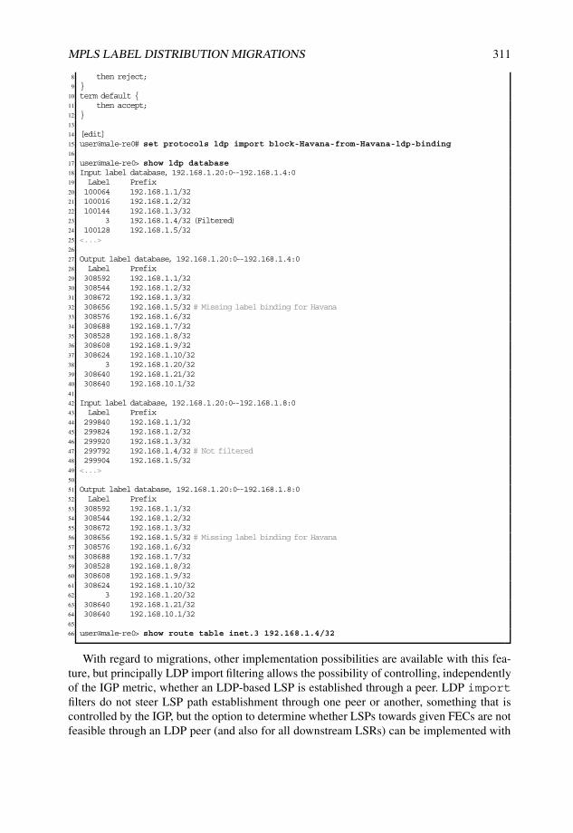
MPLS LABEL DISTRIBUTION MIGRATIONS 311
8 then reject;9 }
10 term default {11 then accept;12 }13
14 [edit]15 user@male-re0# set protocols ldp import block-Havana-from-Havana-ldp-binding16
17 user@male-re0> show ldp database18 Input label database, 192.168.1.20:0--192.168.1.4:019 Label Prefix20 100064 192.168.1.1/3221 100016 192.168.1.2/3222 100144 192.168.1.3/3223 3 192.168.1.4/32 (Filtered)24 100128 192.168.1.5/3225 <...>26
27 Output label database, 192.168.1.20:0--192.168.1.4:028 Label Prefix29 308592 192.168.1.1/3230 308544 192.168.1.2/3231 308672 192.168.1.3/3232 308656 192.168.1.5/32 # Missing label binding for Havana33 308576 192.168.1.6/3234 308688 192.168.1.7/3235 308528 192.168.1.8/3236 308608 192.168.1.9/3237 308624 192.168.1.10/3238 3 192.168.1.20/3239 308640 192.168.1.21/3240 308640 192.168.10.1/3241
42 Input label database, 192.168.1.20:0--192.168.1.8:043 Label Prefix44 299840 192.168.1.1/3245 299824 192.168.1.2/3246 299920 192.168.1.3/3247 299792 192.168.1.4/32 # Not filtered48 299904 192.168.1.5/3249 <...>50
51 Output label database, 192.168.1.20:0--192.168.1.8:052 Label Prefix53 308592 192.168.1.1/3254 308544 192.168.1.2/3255 308672 192.168.1.3/3256 308656 192.168.1.5/32 # Missing label binding for Havana57 308576 192.168.1.6/3258 308688 192.168.1.7/3259 308528 192.168.1.8/3260 308608 192.168.1.9/3261 308624 192.168.1.10/3262 3 192.168.1.20/3263 308640 192.168.1.21/3264 308640 192.168.10.1/3265
66 user@male-re0> show route table inet.3 192.168.1.4/32
With regard to migrations, other implementation possibilities are available with this fea-ture, but principally LDP import filtering allows the possibility of controlling, independentlyof the IGP metric, whether an LDP-based LSP is established through a peer. LDP importfilters do not steer LSP path establishment through one peer or another, something that iscontrolled by the IGP, but the option to determine whether LSPs towards given FECs are notfeasible through an LDP peer (and also for all downstream LSRs) can be implemented with

312 NETWORK MERGERS AND MIGRATIONS
this. For example, Listing 4.5 shows that an LDP path is established only internally to routerHavana whenever the IGP calculation points to router Bilbao as next hop, a behavior thatcan allow other less-preferred protocol label bindings (for example, L-BGP by default) to beselected without needing to tweak protocol preferences. In the case of equal-cost multiplepaths to a destination, LDP import filtering can also determine which of the available siblingpaths is selected, rather than allowing the selection to be done based on other criteria.
All these resources for manipulating and controlling label distribution and for installinglabels with LDP are summarized in the workflow shown in Figure 4.2, which has beensimplified to emphasize the most important tie-breaking design drivers.
Default Junos OSbehavior
LDP policy
Action onown originatedlabel bindings?
Yes No
Yes
No
’egress−policy’
Condition labelbinding
propagation?
No
Yes
Conditionroute
installation?
No Yes’export−policy’ ’import−policy’
FEC allocation to
loopback addresses
only?
Figure 4.2: LDP policy design feature workflow.
4.4.3 Resources for route installation with RSVP-TE
IGP shortcuts for TE
As previously described, Junos OS has a dedicated routing table, inet.3, that contains MPLSLSP destinations, which are routes representing FECs with a legitimate and valid labelbinding. Junos OS considers first by default routes in inet.3 to be representative as next hopsfor all kinds of BGP routes, and only if these next hops are not found in inet.3, Junos OSuses afterwards routes from inet.0 as eligible BGP next hops. Other kinds of traffic, suchas routing protocol flows between IGP-routed addresses, do not make use of this resolutioninfrastructure under those conditions and directly look into inet.0 by default. The rationale forthis default behavior is that BGP is the scalable routing information transport protocol parexcellence, which requires recursive resolution, whereas IGPs are focused on determiningultimate next hops for system reachability, rather than transporting routes.

MPLS LABEL DISTRIBUTION MIGRATIONS 313
This conservative behavior can be relaxed by expanding inet.3 route eligibility to all typesof traffic, not only to BGP routes, by activating IGP shortcuts. In that situation, all MPLSnext hops are moved from inet.3 to inet.0 and therefore become feasible for other types oftraffic, not only BGP. With that strategy, inet.3 is completely emptied and inet.0 becomes therepository for IP and MPLS lookups. The consequence is that MPLS LSPs are also eligiblenext hops in inet.0 (emulating default behavior for other operating systems) for all types oflookup.
In fact, Junos OS performs SPF calculations for route entries and these LSPs are selectedas next hops for destinations located downstream from the egress LSR. This means that LSPselection is not prone to loops for destinations closer to the egress LSRs, because the ingresspoint decides whether traffic to such a destination has to be switched over that LSP by lookinginto the IGP database. This is a sledge-hammer approach to using MPLS LSPs for all kinds oftraffic whenever they are available, based just on a single local decision at the ingress LSR. Inthe end, there are no modifications to any of the standard protocol operations, but rather, it is apurely local routing table decision. One advantage to this method is that it provides the abilityto activate this behavior without influencing any other systems in the IGP area or domain.
Considering domain “Cyclone” as reference scenario, Listing 4.6 shows the consequencesof activating traffic-engineering bgp-igp, with RSVP routes becoming activepaths in inet.0
Apart from replicating other routing vendor’s default behavior to reach IGP routes overMPLS LSPs, IGP shortcuts can be helpful when facing migrations to hide an IGP core withthe MPLS substrate and, especially, to indirectly avoid internal IP lookups inside the coretowards destinations beyond the LSP egress point. Those routes selected by the ingress LSRsto be beyond the LSPs are automatically MPLS-switched with no need to inject a specificlabel binding for them using any MPLS LSP, that is to say, traffic can be MPLS-switched todestinations without any specific label binding in any MPLS LDP.
However, this feature is not granular: it is all or nothing! Despite being a purely localdecision without involving any other systems in the domain, these IGP shortcuts cannot befine-tuned by destination, FEC, VPN or even by LSP.
Listing 4.6: Traffic-engineering bgp-igp at Livorno
1 [edit protocols mpls]2 user@Livorno# show3 traffic-engineering bgp-igp;4 label-switched-path Livorno-to-Skopie {5 to 192.168.1.2;6 }7 label-switched-path Livorno-to-Barcelona {8 to 192.168.1.7;9 }
10 label-switched-path Livorno-to-Honolulu {11 to 192.168.1.21;12 }13 <...>14
15 user@Livorno> show route table inet.0 192.168.1.0/2416
17 inet.0: 38 destinations, 48 routes (37 active, 0 holddown, 3 hidden)18 + = Active Route, - = Last Active, * = Both19
20 <...>21 192.168.1.2/32 *[RSVP/7] 00:00:39, metric 64 # RSVP route as active path in inet.022 > via so-0/0/0.0, label-switched-path Livorno-to-Skopie23 [OSPF/10] 00:00:39, metric 64

314 NETWORK MERGERS AND MIGRATIONS
24 > via so-0/0/0.025 192.168.1.6/32 *[Direct/0] 2d 19:03:5626 > via lo0.027 192.168.1.7/32 *[RSVP/7] 00:00:39, metric 10 # RSVP route as active path in inet.028 > to 172.16.1.53 via ge-0/2/0.0, label-switched-path Livorno-to-Barcelona29 [OSPF/10] 00:00:39, metric 1030 > to 172.16.1.53 via ge-0/2/0.031 192.168.1.21/32 *[RSVP/7] 00:00:39, metric 10 # RSVP route as active path in inet.032 > to 172.16.1.90 via ge-1/3/0.0, label-switched-path Livorno-to-Honolulu33 [OSPF/10] 00:00:39, metric 1034 > to 172.16.1.90 via ge-1/3/0.035 <...>
A collateral effect occurs in Junos OS when electing the routes to be reachable via MPLSLSPs: LSP FECs are injected into inet.0 thanks to the label binding and inet.3 is emptied bythis action.
Because inet.3 is designed to contain MPLS LSP destinations, Junos OS properly resolvesany kind of MPLS VPN route when the next hop for the advertisement is present in inet.3.Indirectly, this behavior makes other destinations beyond MPLS LSP egress points reachablethrough them, but also causes these label bindings to be no longer eligible as next hops forany kind of VPN route.
In an attempt to have the best of both worlds, another knob was conceived: traffic-engineering bgp-igp-both-ribs. With it, both objectives are achieved: MPLSLSP destinations are copied to inet.0 to allow routes beyond to be reachable through them,and these same destinations are kept in inet.3 for proper VPN route resolution. In the end,the same routes derived from active label bindings are present in both tables! This is alsoanother all-or-nothing feature: it cannot be granularly tweaked on a per-LSP-destination orVPN basis; it applies to all active paths with label bindings.
Listing 4.7 illustrates the differential effect in domain “Cyclone” when activating thatfeature in Livorno. Note that the same RSVP routes are present in both inet.0 and inet.3with the same attributes (in fact, similar mechanisms to rib-groups are internally usedfor this).
Listing 4.7: Traffic-engineering bgp-igp-both-ribs at Livorno
1 [edit protocols mpls]2 user@Livorno# show3 traffic-engineering bgp-igp-both-ribs;4 label-switched-path Livorno-to-Skopie {5 to 192.168.1.2;6 }7 label-switched-path Livorno-to-Barcelona {8 to 192.168.1.7;9 }
10 label-switched-path Livorno-to-Honolulu {11 to 192.168.1.21;12 }13 <...>14
15 user@Livorno> show route table inet.0 192.168.1.0/2416
17 # RSVP routes in inet.018
19 inet.0: 38 destinations, 48 routes (37 active, 0 holddown, 3 hidden)20 + = Active Route, - = Last Active, * = Both21
22 <...>23 192.168.1.2/32 *[RSVP/7] 00:00:07, metric 6424 > via so-0/0/0.0, label-switched-path Livorno-to-Skopie25 [OSPF/10] 00:02:52, metric 64
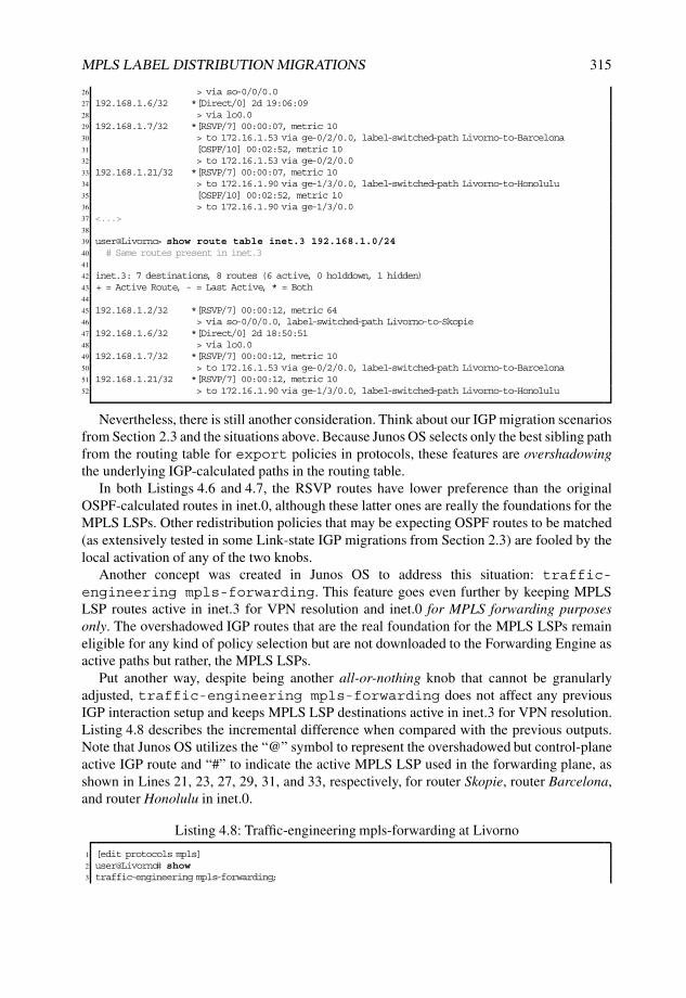
MPLS LABEL DISTRIBUTION MIGRATIONS 315
26 > via so-0/0/0.027 192.168.1.6/32 *[Direct/0] 2d 19:06:0928 > via lo0.029 192.168.1.7/32 *[RSVP/7] 00:00:07, metric 1030 > to 172.16.1.53 via ge-0/2/0.0, label-switched-path Livorno-to-Barcelona31 [OSPF/10] 00:02:52, metric 1032 > to 172.16.1.53 via ge-0/2/0.033 192.168.1.21/32 *[RSVP/7] 00:00:07, metric 1034 > to 172.16.1.90 via ge-1/3/0.0, label-switched-path Livorno-to-Honolulu35 [OSPF/10] 00:02:52, metric 1036 > to 172.16.1.90 via ge-1/3/0.037 <...>38
39 user@Livorno> show route table inet.3 192.168.1.0/2440 # Same routes present in inet.341
42 inet.3: 7 destinations, 8 routes (6 active, 0 holddown, 1 hidden)43 + = Active Route, - = Last Active, * = Both44
45 192.168.1.2/32 *[RSVP/7] 00:00:12, metric 6446 > via so-0/0/0.0, label-switched-path Livorno-to-Skopie47 192.168.1.6/32 *[Direct/0] 2d 18:50:5148 > via lo0.049 192.168.1.7/32 *[RSVP/7] 00:00:12, metric 1050 > to 172.16.1.53 via ge-0/2/0.0, label-switched-path Livorno-to-Barcelona51 192.168.1.21/32 *[RSVP/7] 00:00:12, metric 1052 > to 172.16.1.90 via ge-1/3/0.0, label-switched-path Livorno-to-Honolulu
Nevertheless, there is still another consideration. Think about our IGP migration scenariosfrom Section 2.3 and the situations above. Because Junos OS selects only the best sibling pathfrom the routing table for export policies in protocols, these features are overshadowingthe underlying IGP-calculated paths in the routing table.
In both Listings 4.6 and 4.7, the RSVP routes have lower preference than the originalOSPF-calculated routes in inet.0, although these latter ones are really the foundations for theMPLS LSPs. Other redistribution policies that may be expecting OSPF routes to be matched(as extensively tested in some Link-state IGP migrations from Section 2.3) are fooled by thelocal activation of any of the two knobs.
Another concept was created in Junos OS to address this situation: traffic-engineering mpls-forwarding. This feature goes even further by keeping MPLSLSP routes active in inet.3 for VPN resolution and inet.0 for MPLS forwarding purposesonly. The overshadowed IGP routes that are the real foundation for the MPLS LSPs remaineligible for any kind of policy selection but are not downloaded to the Forwarding Engine asactive paths but rather, the MPLS LSPs.
Put another way, despite being another all-or-nothing knob that cannot be granularlyadjusted, traffic-engineering mpls-forwarding does not affect any previousIGP interaction setup and keeps MPLS LSP destinations active in inet.3 for VPN resolution.Listing 4.8 describes the incremental difference when compared with the previous outputs.Note that Junos OS utilizes the “@” symbol to represent the overshadowed but control-planeactive IGP route and “#” to indicate the active MPLS LSP used in the forwarding plane, asshown in Lines 21, 23, 27, 29, 31, and 33, respectively, for router Skopie, router Barcelona,and router Honolulu in inet.0.
Listing 4.8: Traffic-engineering mpls-forwarding at Livorno
1 [edit protocols mpls]2 user@Livorno# show3 traffic-engineering mpls-forwarding;

316 NETWORK MERGERS AND MIGRATIONS
4 label-switched-path Livorno-to-Skopie {5 to 192.168.1.2;6 }7 label-switched-path Livorno-to-Barcelona {8 to 192.168.1.7;9 }
10 label-switched-path Livorno-to-Honolulu {11 to 192.168.1.21;12 }13 <...>14
15 user@Livorno> show route table inet.0 192.168.1.0/2416
17 inet.0: 38 destinations, 48 routes (37 active, 0 holddown, 3 hidden)18 + = Active Route, - = Last Active, * = Both19
20 <...>21 192.168.1.2/32 @[OSPF/10] 00:04:47, metric 64 # IGP route for Livorno22 > via so-0/0/0.023 #[RSVP/7] 00:00:08, metric 64 # MPLS LSP for Livorno24 > via so-0/0/0.0, label-switched-path Livorno-to-Skopie25 192.168.1.6/32 *[Direct/0] 2d 19:06:0926 > via lo0.027 192.168.1.7/32 @[OSPF/10] 00:04:47, metric 10 # IGP route for Barcelona28 > to 172.16.1.53 via ge-0/2/0.029 #[RSVP/7] 00:00:08, metric 10 # MPLS LSP for Barcelona30 > to 172.16.1.53 via ge-0/2/0.0, label-switched-path Livorno-to-Barcelona31 192.168.1.21/32 @[OSPF/10] 00:04:47, metric 10 # IGP route for Honolulu32 > to 172.16.1.90 via ge-1/3/0.033 #[RSVP/7] 00:00:07, metric 10 # MPLS LSP for Honolulu34 > to 172.16.1.90 via ge-1/3/0.0, label-switched-path Livorno-to-Honolulu35 <...>36
37 user@Livorno> show route table inet.3 192.168.1.0/2438
39 inet.3: 7 destinations, 8 routes (6 active, 0 holddown, 1 hidden)40 + = Active Route, - = Last Active, * = Both41
42 192.168.1.2/32 *[RSVP/7] 00:00:13, metric 6443 > via so-0/0/0.0, label-switched-path Livorno-to-Skopie44 192.168.1.6/32 *[Direct/0] 2d 18:52:4645 > via lo0.046 192.168.1.7/32 *[RSVP/7] 00:00:13, metric 1047 > to 172.16.1.53 via ge-0/2/0.0, label-switched-path Livorno-to-Barcelona48 192.168.1.21/32 *[RSVP/7] 00:00:12, metric 1049 > to 172.16.1.90 via ge-1/3/0.0, label-switched-path Livorno-to-Honolulu
Additional prefix association to RSVP-TE MPLS LSPs
As previously seen, Junos OS only associates the configured FEC with a particular RSVP-TE-steered LSP by default. FECs tend to correspond to egress LSR host addresses and theseroutes may not suffice in certain scenarios, in which it is well known that other destinationsare reachable beyond the LSP destination by design.
However, Junos OS has another granular knob to install additional routes over a commonRSVP-TE LSP: install. This feature allows the configuration of additional destinationprefixes over an LSP. These prefixes therefore appear in inet.3, together with the MPLS LSPegress point, and become eligible next hops for MPLS VPNs.
This behavior may not suffice in some scenarios that need actually to forward traffic tothose destinations, not only to make them feasible next hops. In Junos OS, this means thatsuch destinations should not appear in inet.3, but in inet.0. The install knob has beencomplemented with an active suffix to indicate the desire to inject the prefix into inet.0

MPLS LABEL DISTRIBUTION MIGRATIONS 317
instead of inet.3. In this way, MPLS switching can take place for that destination aggregateuntil the LSP egress point, and at that point, an IP lookup should ensure final reachability,instead of making this additional prefix a next hop available beyond the LSP.
This feature provides an additional tool to control traffic association with an LSP:destinations can be associated on a granular, per-LSP basis. This is also a purely localdecision at the ingress point and is not explicitly related to any protocol mechanism: prefixesare statically bound at the ingress point for resolution in inet.3 or for forwarding in inet.0with the active knob. It provides, therefore, the benefits of traffic control at the ingressLSR bound to a downstream on-demand label solicitation for the LSP FEC, along with thecollateral effects of such granularity. For a global domain-wide association, this behaviorneeds to be replicated at all ingress points, rather than the downstream unsolicited behaviorof LDP tunneling over RSVP-TE, in which the egress LSR controls label association.
Listing 4.9 describes the effect and configuration changes needed to activate the associa-tion of 192.168.10.1/32 at router Livorno over its LSP to router Barcelona with the installknob and the active suffix. Note that this prefix is not included as part of any RSVP object,as depicted starting from Line 20 with a trace options excerpt for the RSVP-TE Path message.It is also worth highlighting that the active knob moves the prefix destination to inet.0,without keeping a copy into inet.3: it has the equivalent effect of setting a static route ininet.0 to an RSVP-TE LSP, as seen in Line 44.
Listing 4.9: Installing external aggregate over LSP to Barcelona in Livorno
1 [edit protocols mpls label-switched-path Livorno-to-Barcelona]2 user@Livorno# set install 192.168.10.1/323
4 user@Livorno> show route 192.168.10.1/32 exact5
6 inet.0: 28 destinations, 30 routes (27 active, 0 holddown, 1 hidden)7 + = Active Route, - = Last Active, * = Both8
9 192.168.10.1/32 *[OSPF/150] 00:10:07, metric 0, tag 010 > to 172.16.1.53 via ge-0/2/0.011
12 inet.3: 5 destinations, 5 routes (4 active, 0 holddown, 1 hidden)13 + = Active Route, - = Last Active, * = Both14
15 192.168.10.1/32 *[RSVP/7] 00:00:05, metric 1016 > to 172.16.1.53 via ge-0/2/0.0, label-switched-path Livorno-to-Barcelona17
18 *** ’rsvp-traceoptions’ has been created ***19 Jul 12 17:27:25.420391 task_timer_dispatch: calling RSVP_RSVP SESSION, late by 0.00120 Jul 12 17:27:25.420591 RSVP send Path 192.168.1.6->192.168.1.7 Len=212 ge-0/2/0.0 # Path message
from Livorno to Barcelona21 Jul 12 17:27:25.420620 Session7 Len 16 192.168.1.7(port/tunnel ID 52104 Ext-ID 192.168.1.6) Proto 022 Jul 12 17:27:25.420644 Hop Len 12 172.16.1.53/0x08e3324823 Jul 12 17:27:25.420662 Time Len 8 30000 ms24 Jul 12 17:27:25.420688 SrcRoute Len 12 172.16.1.54 S25 Jul 12 17:27:25.420707 LabelRequest Len 8 EtherType 0x80026 Jul 12 17:27:25.420728 Properties Len 12 Primary path27 Jul 12 17:27:25.420749 SessionAttribute Len 28 Prio (7,0) flag 0x0 ‘‘Livorno-to-Barcelona’’28 Jul 12 17:27:25.420770 Sender7 Len 12 192.168.1.6(port/lsp ID 17)29 Jul 12 17:27:25.420809 Tspec Len 36 rate 0bps size 0bps peak Infbps m 20 M 150030 Jul 12 17:27:25.420829 ADspec Len 48 MTU 150031 Jul 12 17:27:25.420850 RecRoute Len 12 172.16.1.5332 Jul 12 17:27:25.421019 task_send_msg: task RSVP socket 11 length 236 flags MSG_DONTROUTE(4) to
172.16.1.90 out interface ge-1/3/0.033 Jul 12 17:27:25.421077 task_timer_uset: timer RSVP_RSVP SESSION <Touched Processing> set to offset 45
at 17:28:1034 Jul 12 17:27:25.421151 task_timer_dispatch: returned from RSVP_RSVP SESSION, rescheduled in 4535

318 NETWORK MERGERS AND MIGRATIONS
36 [edit protocols mpls label-switched-path Livorno-to-Honolulu]37 user@Livorno# set install 192.168.10.1/32 active38
39 user@Livorno> show route 192.168.10.1/32 exact40
41 inet.0: 28 destinations, 31 routes (27 active, 0 holddown, 1 hidden)42 + = Active Route, - = Last Active, * = Both43
44 192.168.10.1/32 *[RSVP/7] 00:00:05, metric 10 # RSVP route only in inet.045 > to 172.16.1.53 via ge-0/2/0.0, label-switched-path Livorno-to-Barcelona46 [OSPF/150] 00:19:06, metric 0, tag 047 > to 172.16.1.53 via ge-0/2/0.0
Junos Tip: Combining RSVP-TE LSP prefix association with IGP shortcuts
This association of additional prefixes to RSVP-TE LSPs does not exclude the utilizationof IGP shortcuts. In fact, they can be perfectly complemented.
The same routing result from Listing 4.9 can be obtained when combining installand traffic-engineering bgp-igp, as seen in Listing 4.10. This provides theadvantage that active does not need to be explicitly set on each installed prefix, andall LSP destinations, as well as all additionally installed prefixes, are moved to inet.0.
Listing 4.10: Combining additional prefix and IGP shortcuts in Livorno
1 [edit protocols mpls]2 user@Livorno# set traffic-engineering bgp-igp3 [edit protocols mpls label-switched-path Livorno-to-Barcelona]4 user@Livorno# set install 192.168.10.1/325
6 user@Livorno> show route 192.168.10.1/32 exact7
8 inet.0: 28 destinations, 31 routes (27 active, 0 holddown, 1 hidden)9 + = Active Route, - = Last Active, * = Both
10
11 192.168.10.1/32 *[RSVP/7] 00:00:07, metric 10 # RSVP route only in inet.012 > to 172.16.1.53 via ge-0/2/0.0, label-switched-path Livorno-to-Barcelona13 [OSPF/150] 00:23:13, metric 0, tag 014 > to 172.16.1.53 via ge-0/2/0.0
LDP tunneling over RSVP
LDP was originally conceived in [RFC3036] and [RFC3037] for non-traffic-engineeredapplications, but RSVP-TE extensions were precisely defined for that purpose at [RFC3209].As networks grow over time, a full-mesh of RSVP-based LSPs becomes more difficult tooperate and maintain due to an N2 growth path and signaling limitations, and differentscalability concepts are proposed.
One feasible implementation consists of tunneling LDP LSPs over RSVP-TE LSPs.LDP includes resources to support sessions between non-directly connected LSRs, andby tunneling those LSPs, the benefits of providing TE and fast reroute capabilities todownstream unsolicited LSPs can be achieved, combining the advantages of both worlds.The rationale is to tunnel data traffic traversing those LDP LSPs, while targeted LDP controltraffic between remote neighbors remains outside this plane.
In Junos OS, this is implemented by having link-state IGPs using RSVP-TE LSPs in theSPF calculation and adding hidden routes to inet.3 representing each LSP. The reason for

MPLS LABEL DISTRIBUTION MIGRATIONS 319
these routes to remain hidden is to constrain their utilization to LDP and avoid other protocols(BGP by default) being able to use those next hops for resolution. Similarly, those next hopswill be disclosed if TE shortcuts for RSVP-TE are activated.
Also, LDP next-hop tracking is extended for these RSVP-TE LSPs: if they become activenext hops for an LDP FEC, the label advertised by that remote LDP peer reachable throughthe RSVP-TE LSP becomes active. This means a double MPLS label push at the ingressLSR: the inner label to reach the LDP FEC and the outer label to reach the LDP peer viaRSVP-TE LSP. This can also occur in transit between a non-extended LDP and a targetedLDP session, meaning that the programmed action can be an MPLS label swap and push forthe RSVP-TE destination, instead of a double push.
Listing 4.11 shows the necessary configuration steps on router Livorno to activate LDPtunneling over the existing RSVP-TE LSP mesh from domain “Cyclone”. The featureis simply activated by enabling the loopback interface for LDP protocol and adding therespective ldp-tunneling knob at the RSVP-TE LSPs, as shown in Lines 5, 9, and 13.Note that Junos OS presents an additional hook via strict-targeted-hellos tojust limit targeted LDP session establishment to those LDP peers matching destinationsfrom RSVP-TE LSPs configured with ldp-tunneling and do not accept other arbitrarytargeted LDP sessions.
Listing 4.11: LDP tunneling activation over RSVP-TE mesh at Livorno
1 [edit protocols mpls]2 user@Livorno# show3 label-switched-path Livorno-to-Skopie {4 to 192.168.1.2;5 ldp-tunneling; # Activate LDP targeted session over LSP6 }7 label-switched-path Livorno-to-Barcelona {8 to 192.168.1.7;9 ldp-tunneling; # Activate LDP targeted session over LSP
10 }11 label-switched-path Livorno-to-Honolulu {12 to 192.168.1.21;13 ldp-tunneling; # Activate LDP targeted session over LSP14 }15 interface all;16 interface fxp0.0 {17 disable;18 }19
20 [edit protocols ldp]21 user@Livorno# show22 track-igp-metric;23 strict-targeted-hellos; # Limit LDP sessions to be targeted per config24 interface lo0.0;25
26 user@Livorno> show mpls lsp ingress27 Ingress LSP: 3 sessions28 To From State Rt P ActivePath LSPname29 192.168.1.2 192.168.1.6 Up 0 * Livorno-to-Skopie30 192.168.1.7 192.168.1.6 Up 1 * Livorno-to-Barcelona31 192.168.1.21 192.168.1.6 Up 0 * Livorno-to-Honolulu32 Total 3 displayed, Up 3, Down 033
34 user@Livorno> show rsvp neighbor35 RSVP neighbor: 3 learned36 Address Idle Up/Dn LastChange HelloInt HelloTx/Rx MsgRcvd37 172.16.1.33 5 1/0 2d 3:03:20 9 20316/20316 2456938 172.16.1.90 5 3/2 1d 15:18:17 9 20313/20312 1741839 172.16.1.53 5 2/1 1d 22:15:16 9 20237/20215 21409

320 NETWORK MERGERS AND MIGRATIONS
40
41 user@Livorno> show ldp neighbor42 Address Interface Label space ID Hold time43 192.168.1.2 lo0.0 192.168.1.2:0 4444 192.168.1.7 lo0.0 192.168.1.7:0 3145 192.168.1.21 lo0.0 192.168.1.21:0 3546
47 user@Livorno> show ldp session48 Address State Connection Hold time49 192.168.1.2 Operational Open 2650 192.168.1.7 Operational Open 2551 192.168.1.21 Operational Open 24
When routing tables are analyzed in detail, one notices that hidden routes in tableinet.3 are visible for RSVP-TE LSP destinations, so that these shortcuts are eligible forLDP route computations only. Listing 4.12 shows those routing table excerpts from theperspective of router Livorno. In fact, considering a label binding for the externally injectedprefix 192.168.10.1/32 into domain “Cyclone” only in LDP and not as RSVP-TE LSPdestination, the LDP label binding becomes active over the RSVP-TE LSP following anOSPFv2 route. Because of implicit LDP egress-policies at participating LSRs, routerLivorno receives an LDP label binding for each other participating router reachable over thecorresponding RSVP-TE LSP; however, because of default protocol preferences, RSVP ispreferred. Line 21 shows the LDP route preferred for the externally injected prefix, installedover the RSVP-TE LSP, for the closest exit point. Lines 49, 51, 53, and 55 depict hiddenroutes for each destination to be considered for LDP calculations.
Listing 4.12: Routing table effect when activating LDP tunneling at Livorno
1 user@Livorno> show route table inet.32
3 inet.3: 10 destinations, 18 routes (7 active, 0 holddown, 7 hidden)4 + = Active Route, - = Last Active, * = Both5
6 <...>7 192.168.1.2/32 *[RSVP/7] 2d 03:04:32, metric 648 > via so-0/0/0.0, label-switched-path Livorno-to-Skopie9 [LDP/9] 1d 15:19:24, metric 64
10 > via so-0/0/0.0, label-switched-path Livorno-to-Skopie11 192.168.1.6/32 *[Direct/0] 2d 02:51:0612 > via lo0.013 192.168.1.7/32 *[RSVP/7] 1d 22:16:28, metric 1014 > to 172.16.1.53 via ge-0/2/0.0, label-switched-path Livorno-to-Barcelona15 [LDP/9] 1d 15:19:24, metric 1016 > to 172.16.1.53 via ge-0/2/0.0, label-switched-path Livorno-to-Barcelona17 192.168.1.21/32 *[RSVP/7] 1d 15:19:06, metric 1018 > to 172.16.1.90 via ge-1/3/0.0, label-switched-path Livorno-to-Honolulu19 [LDP/9] 1d 15:19:06, metric 1020 > to 172.16.1.90 via ge-1/3/0.0, label-switched-path Livorno-to-Honolulu21 192.168.10.1/32 *[LDP/9] 1d 15:19:24, metric 0 # LDP route over RSVP-TE LSP22 > to 172.16.1.53 via ge-0/2/0.0, label-switched-path Livorno-to-Barcelona23
24 user@Livorno> show route 192.168.10.1/32 extensive table inet.325
26 inet.3: 10 destinations, 18 routes (7 active, 0 holddown, 7 hidden)27 192.168.10.1/32 (2 entries, 2 announced)28 State: <FlashAll>29 *LDP Preference: 930 Next hop type: Router31 Next-hop reference count: 432 Next hop: 172.16.1.53 via ge-0/2/0.0 weight 0x1, selected33 Label-switched-path Livorno-to-Barcelona # RSVP-TE LSP as next hop34 State: <Active Int>35 Local AS: 65001

MPLS LABEL DISTRIBUTION MIGRATIONS 321
36 Age: 1d 15:27:07 Metric: 037 Task: LDP38 Announcement bits (2): 2-Resolve tree 1 3-Resolve tree 239 AS path: I40
41 user@Livorno> show route table inet.3 hidden42
43 # Hidden shortcuts for LDP computation44
45 inet.3: 10 destinations, 18 routes (7 active, 0 holddown, 7 hidden)46 + = Active Route, - = Last Active, * = Both47
48 <...>49 192.168.1.2/32 [OSPF] 2d 03:05:37, metric 6450 > via so-0/0/0.0, label-switched-path Livorno-to-Skopie51 192.168.1.7/32 [OSPF] 1d 22:17:33, metric 1052 > to 172.16.1.53 via ge-0/2/0.0, label-switched-path Livorno-to-Barcelona53 192.168.1.21/32 [OSPF] 1d 15:20:11, metric 1054 > to 172.16.1.90 via ge-1/3/0.0, label-switched-path Livorno-to-Honolulu55 192.168.10.1/32 [OSPF] 1d 22:17:33, metric 0, tag 056 > to 172.16.1.53 via ge-0/2/0.0, label-switched-path Livorno-to-Barcelona
The applicability of LDP tunneling for MPLS transport migration purposes resides in itssimplicity to extend and merge LDP clouds: MPLS domains can be easily stitched over atransit RSVP-TE LSP core or interconnected just by activating the feature and letting LDPlabel bindings be populated (this also requires that IGP routes be manipulated in a similarfashion). It is a very simple mechanism to unify LDP domains and presents the advantageof interacting perfectly, and with no further resources, with non-targeted LDP sessions atthe RSVP-TE ingress LSRs. Thus, LDP tunneling becomes also a practical downstreamunsolicited label distribution implementation over an RSVP-TE LSP mesh, in which LDPlabel bindings can be fine-tuned via LDP egress and export policies at boundary routers.
A simplified view of these features, which determine RSVP-TE route installation and labeldistribution, is shown in Figure 4.3 to illustrate differences among them that lead to particulardesign criteria.
4.4.4 Resources for label advertisement and route resolution withLabeled BGP
Route resolution for Labeled BGP
The Labeled BGP address family (AFI 1, SAFI 4) is explicitly activated at each BGP peerwith the family inet labeled-unicast configuration option. This knob allowseach neighbor to negotiate this family type and to signal LSPs for FECs represented by IPprefixes with labels, as per [RFC3107]. Per the default action with BGP, these routes, alongwith their labels, are installed in Junos OS in inet.0. While this route installation can be aperfect fit for standard route resolution pointing to those next hops, Junos OS requires thatMPLS VPN applications resolve over next hops present in inet.3, indicating that a labelbinding is present for that FEC in the dedicated table. Similarly to LDP and RSVP-TE,L-BGP routes can also be installed in inet.3 in different ways.
inet.3 as primary table for L-BGP: Junos OS allows the one-to-one relationship betweenBGP NLRI and table to be modified granularly. The rib inet.3 knob for the labeled-unicast family associates inet.3 as the primary table into which L-BGP routes are installedalong with their labels.

322 NETWORK MERGERS AND MIGRATIONS
’traffic−engineringbgp−igp’
RSVP−TE policy
UnilateralMPLS switching
for ALLdestinations?
Yes No
No
Yes
Extradestinationsgranularlyat Ingress
LSR?
No
Yes
’ldp−tunneling’
Need IGP routeseligible forpolicies?
Yes
’traffic−engineringmpls−forwarding’
No’traffic−engineringbgp−igp−both−ribs’
Extradestinationsgranularlyat Egress
LSR?
’install’
’active’Yes
No
Yes
Yes
Default Junos OS behavior(’traffic−engineeringbgp’)
No
NoActivate
destinations granularly in
inet.0?
Needdestinations in
inet.0?(MPLS
forwarding)
Needdestinations in
inet.3?(MPLS VPNresolution)
Figure 4.3: RSVP-TE design criteria and tie-breakers.
This behavior still allows standard BGP IPv4 unicast routes to use inet.0 as theircorresponding table, with a unique BGP family-table liaison, and then to advertise prefixesfor different purposes with different families. Junos OS also offers enough versatility with itspolicy language to apply different BGP TE rules on a per-family basis.
When activating this option, a behavior similar to advertise-inactive is internally enabledon this specific family, because it is expected to resolve those L-BGP routes (usually routerloopbacks) over RSVP or LDP for proper resolution, and thus, these L-BGP routes maybecome inactive paths in the routing table when overlapping with RSVP-TE or LDP FECsfor the same destinations.
The main advantages of using inet.3 are that other routes present in that table are directlyeligible for export, and that imported routes and labels are already placed in inet.3. No furthertweaks are then needed to redistribute LDP or RSVP signaled FECs into L-BGP, because theyuse a common container as table. On the other hand, inet.3 becomes the route resolution RIB,so any resolution apart from directly connected routes (that is, L-IBGP, confederation L-BGP,or multihop L-EBGP) requires that the corresponding next hop is present in inet.3.
It may also be desirable to place these routes in inet.0 for standard IPv4 route resolutionpurposes. This can be also achieved by attaching a standard rib-group to the family, thusimporting inet.3 routes into inet.0 as well.
Copying Labeled BGP routes into inet.3: Another option offered by Junos OS is tomaintain inet.0 as primary table for L-BGP routes, but to allow MPLS VPN resolution overthem by automatically copying those routes to inet.3
The resolve-vpn option for the labeled-unicast family internally activatesa rib-group that imports these routes both into inet.0 as primary table and inet.3 assecondary copies.

MPLS LABEL DISTRIBUTION MIGRATIONS 323
This alternative allows resolution for MPLS VPNs with the secondary copies present ininet,3 but installs and exports routes from inet.0, so they are then also eligible for standardIPv4 lookup actions.
Junos Tip: Primary routing table exclusiveness for L-BGP routes
Both L-BGP route resolution options are mutually exclusive and Junos OS enforces thisdecision. The rib inet.3 option takes precedence when both are configured, with theunderstanding that setting a primary table has higher significance. The user is also notifiedof this behavior by means of a commit warning, as per Listing 4.13.
Listing 4.13: L-BGP route resolution exclusiveness
1 [edit protocols bgp]2 user@Basel# show3 group IBGP {4 type internal;5 local-address 192.168.1.10;6 family inet {7 unicast;8 labeled-unicast {9 rib {
10 inet.3;11 }12 resolve-vpn;13 }14 }15 export bind-local-label;16 <...>17 }18 user@Basel# commit and-quit19 [edit protocols bgp group IBGP family inet]20 ’labeled-unicast’21 BGP: Warning: resolve-vpn keyword ignored - primary table is inet.322 commit complete23 Exiting configuration mode
Label advertisement for Labeled BGP
As per general rule, in L-BGP the associated label is changed in Junos OS with everynext-hop change for the route. This means that the standard next-hop change whentransitioning from internal to external L-BGP, or vice versa, indirectly leads to a label swap(or pop if one of the labels is implicit-null). In other situations, such as L-IBGP routereflection, confederated L-BGP sessions with specific next-hop setting policies, and directadvertisements from an L-EBGP session to another L-EBGP peer (without a joint sharedbroadcast media for third-party next-hop advertisement), labels included in the NLRI arechanged in Junos OS when readvertising the route, and the MPLS action (label swap or pop)is installed in the forwarding table mpls.0.
Advertising null label for connected routes: Junos OS also allows advertising an explicit-null label (0 for IPv4, 2 for IPv6) for directly connected routes (actually for both inet and inet6labeled-unicast families).
The default behavior is to advertise the implicit-null label (3 for inet labeled-unicast) toenforce penultimate-hop popping. With regard to migrations, there are certain setups in which

324 NETWORK MERGERS AND MIGRATIONS
an MPLS label is always needed end to end, for instance, to enforce MPLS CoS settingsbetween L-BGP ASBRs or, especially, to avoid an IP lookup at some point. Listing 4.14illustrates changes in router Livorno before and after activating the explicit-null knob.
Listing 4.14: L-BGP explicit null advertisement for connected routes
1 user@Livorno> show route advertising-protocol bgp 172.16.1.37 192.168.1.6 extensive2
3 inet.3: 10 destinations, 18 routes (8 active, 0 holddown, 5 hidden)4 * 192.168.1.6/32 (1 entry, 1 announced)5 BGP group L-EBGP type External6 Route Label: 3 # Implicit null7 Nexthop: Self8 Flags: Nexthop Change9 AS path: [64501] I
10
11 user@Livorno> configure12 Entering configuration mode13 [edit protocols bgp group L-EBGP]14 user@Livorno# set family inet labeled-unicast explicit-null connected-only15 [edit protocols bgp group L-EBGP]16 user@Livorno# commit and-quit17 commit complete18 Exiting configuration mode19 user@Livorno> show route advertising-protocol bgp 172.16.1.37 192.168.1.6 extensive20
21 inet.3: 10 destinations, 18 routes (8 active, 0 holddown, 5 hidden)22 * 192.168.1.6/32 (1 entry, 1 announced)23 BGP group L-EBGP type External24 Route Label: 0 # Explicit null25 Nexthop: Self26 Flags: Nexthop Change27 AS path: [64501] I
Two figures provide an overview of all the design knobs in Junos OS related toL-BGP. Figure 4.4 shows a simple route injection design workflow, and Figure 4.5 showsthe workflow for a label allocation scheme.
4.5 Case Study
The same company acquisition scenario from previous chapters is used in our case studyhere. Integrating MPLS-based applications is fairly common in a network merger scenario,and sometimes it is actually the ultimate goal of a migration.
Extending and integrating MPLS label distribution protocols over the network topologyensures that those end-to-end MPLS-based applications can be provisioned and operatedamong participating networks.
4.5.1 Original network
Considering the same initial setups for merging into a common service provider “GaleInternet,” MPLS domains also need to be integrated. As a parallel exercise to integrating link-state IGPs and BGP, MPLS label distribution protocols will be integrated with the intentionto have a final joint MPLS domain. Taking into account MPLS transport support in each ofthe single initial domains, as depicted in Figure 4.6, domain “Monsoon” did not previouslyoffer any kind of MPLS service, although domain “Mistral” is using LDP as the current
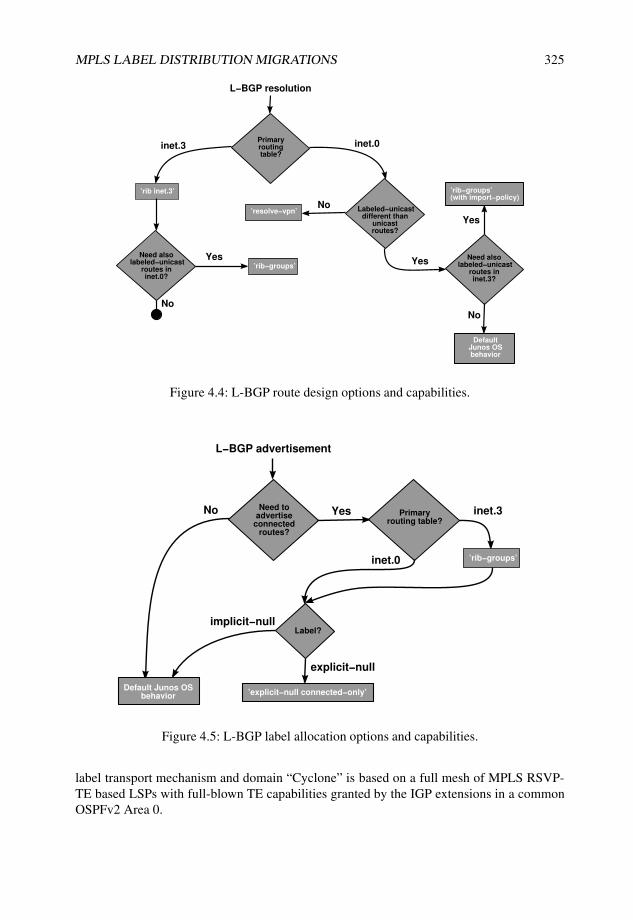
MPLS LABEL DISTRIBUTION MIGRATIONS 325
L−BGP resolution
Primaryroutingtable?
inet.3 inet.0
Yes
No
’rib−groups’Yes
’rib inet.3’
Need alsolabeled−unicast
routes ininet.0?
Labeled−unicastdifferent than
unicastroutes?
’resolve−vpn’
Need alsolabeled−unicast
routes ininet.3?
Yes
No
Default Junos OSbehavior
No
’rib−groups’(with import−policy)
Figure 4.4: L-BGP route design options and capabilities.
L−BGP advertisement
Need toadvertise
connectedroutes?
No Yes
Default Junos OSbehavior
Primaryrouting table?
inet.3
’rib−groups’
Label?
inet.0
implicit−null
’explicit−null connected−only’
explicit−null
Figure 4.5: L-BGP label allocation options and capabilities.
label transport mechanism and domain “Cyclone” is based on a full mesh of MPLS RSVP-TE based LSPs with full-blown TE capabilities granted by the IGP extensions in a commonOSPFv2 Area 0.

326 NETWORK MERGERS AND MIGRATIONS
Area 0.0.0.0
TE extensions
Co
st
10
00
LDP
RSVP−TEMale
Bilbao
Havana
Nantes
Skopie
Livorno
Barcelona
Honolulu
192.168.1.4
192.168.1.20
192.168.1.8
10.10.1.1
192.168.1.2
192.168.1.6
192.168.1.7
192.168.1.21
Torino
Lille
10.10.1.9
Inverness
Basel
192.168.1.5
10.10.1.3
10.10.1.10
OSPFv2
domain "Monsoon"
AS64503
IS−IS and LDP
domain "Mistral"
AS64502OSPFv2 and RSVP−TE
domain "Cyclone"
AS64501
NOC mgmt
center
AS65500
Figure 4.6: Original topology including MPLS label distribution protocols support at eachdomain.
In terms of BGP, the initial situation illustrated in Figure 3.9 is considered as thebackground scenario for eventual L-BGP deployment. Each domain is represented by adifferent and independent AS, which is not yet confederated or integrated, and the samemesh topology is intended to be used if needed.
Top management has also set as a parallel goal to initially integrate and connect bothMPLS domains in a redundant fashion, and as final objective a joint integration into a unifiedMPLS domain with common rules and label distribution mechanisms.
As first milestone for the merging, it is understood that a consistent setup is created withlabel-binding transport across the existing domains that offer MPLS services, namely domain“Mistral” and domain “Cyclone”. This setup should allow MPLS VPNs to be stretched overthe recently acquired infrastructure as soon as an initial label-binding transport integrationoccurs. This first interconnect must also comply with the usual redundancy and resiliencerequirements to survive against as many single points of failure as possible.
After this first milestone, once all domains have been merged into a common link-stateIGP, a gradual migration to a unified label transport protocol is scoped.
4.5.2 Target network
Considering all parallel migration exercises, the final topology includes a unique MPLS labeldistribution protocol in parallel to a unified link-state IGP and BGP setup. Depending on thestatus of other migrations, two major milestones have been defined:
• interconnect MPLS domains to be able to provide services end-to-end;
• integrate all systems under a common MPLS label distribution protocol.
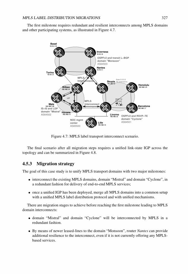
MPLS LABEL DISTRIBUTION MIGRATIONS 327
The first milestone requires redundant and resilient interconnects among MPLS domainsand other participating systems, as illustrated in Figure 4.7.
Male
Bilbao
Havana
Nantes
Skopie
Livorno
Barcelona
Honolulu
192.168.1.4
192.168.1.20
192.168.1.8
10.10.1.1
192.168.1.2
192.168.1.6
192.168.1.7
192.168.1.21
Torino
Lille
10.10.1.9
Inverness
Basel
192.168.1.5
10.10.1.3
10.10.1.10
OSPFv2 and transit L−BGP
domain "Monsoon"
AS64503
IS−IS and LDP
domain "Mistral"
AS64502OSPFv2 and RSVP−TE
domain "Cyclone"
AS64501NOC mgmt
center
AS65500
LDP
Area 0.0.0.0
TE extensions
RSVP−TE
Full meshMPLS
Interconnect
MPLS
Interconnects
Figure 4.7: MPLS label transport interconnect scenario.
The final scenario after all migration steps requires a unified link-state IGP across thetopology and can be summarized in Figure 4.8.
4.5.3 Migration strategy
The goal of this case study is to unify MPLS transport domains with two major milestones:
• interconnect the existing MPLS domains, domain “Mistral” and domain “Cyclone”, ina redundant fashion for delivery of end-to-end MPLS services;
• once a unified IGP has been deployed, merge all MPLS domains into a common setupwith a unified MPLS label distribution protocol and with unified mechanisms.
There are migration stages to achieve before reaching the first milestone leading to MPLSdomain interconnects:
• domain “Mistral” and domain “Cyclone” will be interconnected by MPLS in aredundant fashion.
• By means of newer leased-lines to the domain “Monsoon”, router Nantes can provideadditional resilience to the interconnect, even if it is not currently offering any MPLS-based services.

328 NETWORK MERGERS AND MIGRATIONS
Male
Bilbao
Havana
Nantes
Skopie
Livorno
Barcelona
Honolulu
192.168.1.4
192.168.1.20
192.168.1.8
192.168.1.1
192.168.1.2
192.168.1.6
192.168.1.7
192.168.1.21
Torino
Lille
192.168.1.9
Inverness
Basel
192.168.1.5
192.168.1.3
192.168.1.10
Common
MPLS label
distribution
protocol
Across IS−IS levels
NOC mgmt
center
Cost 1000
L1
L2
L2
L2
L2
L2
L2
L1
L1
L1
L2
L1
L1
L1
Figure 4.8: Final MPLS label distribution topology.
• Router Lille is the router providing transit services for the NOC, and as such, it initiallyoffers no MPLS VPNs. However, the plan is to integrate this domain as soon aspossible, because the NOC folks also need intra-VPN management. For this reason,router Lille will also be interconnected to be able to instantiate VPNs and thus offermanaged services inside each VPN, such as CE activation and configuration.
Once all these steps have been accomplished, the final MPLS domain migration requiresa unified link-state IGP on all routers and can be accomplished only when this prerequisiteis met. For this reason, all changes to reach the first milestone need to remain stable andindependent of any IGP changes that may occur during transient phases.
As with other migrations, redundancy and minimal impact are principal goals of theprocess. MPLS-based services are financially crucial for “Gale Internet,” and operationalturbulences with this product could have fatal consequences during the company acquisitionand migration period.
Interconnecting MPLS domains
The first design decision to make is the choice for the glue to stitch both domains together ina resilient fashion.
The idea is to make use of any of the existing available MPLS label distribution protocolsto distribute such label bindings across domains. Consider the existing protocols:
• RSVP-TE: is implemented on available information from the TED. In this case, thereis no joint TED, so interdomain RSVP LSPs would not be precalculated from available

MPLS LABEL DISTRIBUTION MIGRATIONS 329
information but rather, would be purely signaled across interconnects. This mechanismlacks some transparency for events in the other domain and requires additional hooksto refer to existing FECs in the IGP at each domain.
• LDP: usually relies on IGPs to determine the active label binding, but at this point, thereis no unified link-state IGP. When supporting interarea, interdomain, or hierarchicalLDP, less specific FEC route-matching is needed for selecting the label binding. Thisrequirement imposes the need to at least redistribute some aggregates and adds opacityin a redundant interconnect, as well as requiring support for that feature.
• L-BGP: relies only on IGPs for internal peer reachability, which is BGP’s standardbehavior for internal sessions. However, BGP is decoupled from the IGP whenadvertising label bindings with EBGP, and Junos OS offers resources to determinewhether those routes are installed in inet.0, inet.3 or both. As per standard BGPUPDATE messages propagation, the NLRI for each specific route is populated ina transparent and immediate fashion, without affecting any other label bindingsfrom the same domain. Existing BGP attributes also enable the fine-tuning of routeadvertisement among domains as well as the implementation of an optimal andredundant route reachability scheme.
In this environment, L-BGP is elected as the vehicle of choice to transport labelbindings across domains. The fundamental differences to sway the balance are its completeindependence from a given IGP for granular advertisement and the previous existence ofseparate BGP ASs for each domain. L-BGP as label distribution protocol also ensures aneasy transition by just activating the required labeled unicast family on existing BGPmesh topologies and adapting redistribution policies where necessary.
Furthermore, even though domain “Monsoon” does not provide any MPLS services, itis connected using the new leased lines to both domain “Mistral” and domain “Cyclone”.Just by enabling external L-BGP among router Nantes, router Bilbao, and router Skopie,together with MPLS activation over both external links, an additional path is establishedwithout the need to redistribute routes or aggregates. This extra path enforces the redundancyrequirements for the initial stage and at the same time opens the door for offering MPLS-based services even inside domain “Monsoon”.
Another consideration needs to be made after discussing domain interconnection: externallabel binding distribution inside each domain. Two different approaches are feasible basedon the previous choice of interconnect methodology:
• Redistribution: external label bindings can be redistributed at ASBRs inside eachdomain for further internal population. In the case of domain “Cyclone”, RSVP-TE would need to be used as the substrate for another downstream unsolicited labeldistribution protocol to distribute those external bindings in a flexible manner. Fordomain “Mistral”, because LDP follows IGP routes, these externally injected prefixeswould need to be redistributed into the IGP as well.
• Overlay: internal L-BGP resolving over another substrate in inet.3 can be deployedover LDP and RSVP-TE, at domain “Mistral” and domain “Cyclone”, respectively.
The internal L-BGP overlay model clearly benefits from seamless integration, becauseit requires no manipulation of existing internal IGPs or MPLS label distribution protocols

330 NETWORK MERGERS AND MIGRATIONS
at each domain. It also provides smooth label-binding propagation to each internal router aspart of the standard route advertisement mechanisms between IBGP and EBGP, together withgranular TE mechanisms inherent in BGP.
In a nutshell, L-BGP is selected as the protocol not only to interconnect domains but alsoto provide end-to-end label transport between devices at different sites in an overlay fashionover the existing, underlying label distribution protocols within each domain.
Considering the initial stage from the BGP case study in Section 3.6, labeled uni-cast is deployed as an additional family over the existing BGP virtual topologies in eachdomain, namely:
• full IBGP mesh in domain “Cyclone”;
• route reflection with router Male as the reflector server for domain “Mistral”.
Figure 4.9 depicts the MPLS interconnect and distribution scenario with all domains androuter Lille, considering such BGP mesh scheme in each domain.
Male
Bilbao
Havana
Nantes
Skopie
Livorno
Barcelona
Honolulu
192.168.1.4
192.168.1.20
192.168.1.8
10.10.1.1
192.168.1.2
192.168.1.6
192.168.1.7
192.168.1.21
Torino
Lille
10.10.1.9
Inverness
Basel
192.168.1.5
10.10.1.3
10.10.1.10
OSPFv2 and transit L−BGP
domain "Monsoon"
AS64503
IS−IS and LDP
domain "Mistral"
AS64502 OSPFv2 and RSVP−TE
domain "Cyclone"
AS64501
NOC mgmt
center
AS65500
L−EBGP
L−EBGP
L−EBGP
L−EBGP
LDP
Area 0.0.0.0
TE extensions
RSVP−TE
Full mesh
L−IBGP
BGP
RR Server
L−IBGP
L−IBGP
L−IBGP L−IBGP
L−IBGP
L−IBGP
Figure 4.9: MPLS label transport interconnect scenario.
For this scenario, the activities to carry out before reaching the first milestone are:
• Deploy internal L-BGP inside domain “Mistral” over the route reflection scheme byadding the labeled-unicast family and external L-BGP on router Bilbao androuter Havana, so they become ASBRs for external interconnects.

MPLS LABEL DISTRIBUTION MIGRATIONS 331
• Deploy internal L-BGP inside domain “Cyclone” over the full-mesh scheme by addingthe labeled-unicast family and external L-BGP on router Skopie and routerLivorno, so they become ASBRs for external interconnects.
• New leased-lines to domain “Monsoon” enable another path that can back up potentialfailures at either router Havana or router Livorno. By establishing external L-BGPsessions between router Bilbao and router Nantes, and between router Nantes androuter Skopie, another backup transit is available between both domain “Mistral” anddomain “Cyclone”.
When first interconnecting domains, note that the label-binding population inside each oneis based on standard BGP route advertisement rules, both in a full-mesh or route reflectionfashion. This means that inside each domain, no redistribution with any of the existinglabel distribution protocols is needed because they are simply used for internal L-BGP routeresolution purposes.
Migration to a common LDP
Once a common and unified IGP domain has been deployed, another evaluation needs to becarried out to plan for the final unified MPLS label distribution protocol.
Discarding RSVP-TE for the previously discussed reasons, L-BGP can retain its func-tionality to bind domains and populate label bindings perfectly in an overlay model.
However, parallel changes in other protocols influence MPLS label distribution as well,namely:
• The IGP is unified in all domains, meaning that a single label distribution protocolfollowing the IGP can be rolled out with no interconnects or redistributions.
• The diverse BGP ASs are unified into a joint global AS, meaning that previous externalconnections now become internal. This change is important for L-BGP in the sense thatanother label distribution protocol needs to be rolled out underneath all these previousexternal connections.
To summarize the requirements, another label distribution protocol needs to be rolled out,at least at the domain interconnects, and label bindings can follow IGP routes, thus forminga consolidated topology.
From a migration perspective, LDP can transition progressively to become the only andglobal MPLS label distribution protocol. While it is legitimate to retain L-BGP to transportlabel bindings, LDP can be deployed as IGPs are merged and can become the underlyingresolution substrate for L-BGP.
All these stages for the MPLS label distribution protocol migration strategy and theirinteraction are shown in Figure 4.10. These stages closely depend on each other in a strictsequence or can be accomplished in parallel until reaching a milestone.
4.5.4 Stage one: Labeled BGP deployment over LDP in domain“Mistral”
As the first step, internal L-BGP needs to be rolled out in domain “Mistral”. By using theexisting LDP as a feasible resolution layer for L-IBGP sessions, this deployment is as simple

332 NETWORK MERGERS AND MIGRATIONS
DifferentMPLSlabel
distributionprotocols at "Cyclone"
and "Mistral"
MPLS domain interconnect1. L−BGP deploymentover LDP in "Mistral"
2. L−BGP deploymentover RSVP−TE in "Monsoon"
4. Redundant L−BGP over "Monsoon"
3. External L−BGP interconnectbetween "Mistral" and "Monsoon"
1st
milest.
MPLS label binding transport among systems
in different domains
6. LDP activation in all domains
Done!
2nd m.
LDP integration
Domains integrated with commonLDP settings
5. L−BGP interconnect via Lille
Global IS−IS integration 7. L−BGP familycleanup (Optional)
Figure 4.10: Strategy for the MPLS label distribution protocol migration.
as extending the existing BGP session infrastructure with the new labeled-unicastfamily.
Because this domain includes two ASBRs that support external L-BGP, the same familyalso needs to be externally activated towards domain “Cyclone” and other routers.
Listing 4.15 illustrates the full BGP configuration at router Bilbao. As per Lines 10and 22, inet.3 is configured as primary table to install L-BGP routes without any specificleaking to inet.0. The idea is to automatically select and feed this table, which is shared withLDP and RSVP-TE in an independent fashion to inet.0.
Listing 4.15: Complete BGP configuration at Bilbao, including internal and external labeledunicast
1 [edit protocols bgp]2 user@Bilbao-re0# show3 group IBGP {4 type internal;5 local-address 192.168.1.8;6 family inet {7 unicast;8 labeled-unicast {9 rib {
10 inet.3; # inet.3 as primary table11 }12 }13 }14 export [ nhs own-loopback ]; # next hop self policy for IBGP routes15 neighbor 192.168.1.20; # Male as route Reflector Server16 }17 group EBGP {18 family inet {

MPLS LABEL DISTRIBUTION MIGRATIONS 333
19 unicast;20 labeled-unicast {21 rib {22 inet.3; # inet.3 as primary table23 }24 }25 }26 export own-loopback;27 peer-as 64503;28 neighbor 172.16.1.6;29 }30
31
32 [edit policy-options policy-statement own-loopback]33 user@Bilbao-re0# show34 term own-loopback {35 from {36 protocol direct; # local loopback address37 rib inet.3; # Enforce loopback presence in inet.338 route-filter 192.168.1.0/24 prefix-length-range /32-/32;39 }40 to rib inet.3;41 then accept;42 }43
44 [edit routing-options]45 user@Bilbao-re0# show46 interface-routes {47 rib-group inet int-to-inet3; # Apply rib-groups to direct routes48 }49 rib-groups {50 int-to-inet3 {51 import-rib [ inet.0 inet.3 ]; # inet.0 as primary, inet.3 as secondary52 import-policy interface-to-inet3; # Route sharing controlled by import policy53 }54 }55 router-id 192.168.1.8;56 autonomous-system 64502;57
58 [edit policy-options policy-statement interface-to-inet3]59 user@Bilbao-re0# show60 term loopback {61 from interface lo0.0; # Just match on loopback address62 then accept;63 }64 term no-more-inet3 {65 to rib inet.3;66 then reject; # Do not import anything else into inet.367 }68 term default {69 to rib inet.0;70 then accept; # allow default accept for primary table inet.071 }
Note that each router needs to advertise a label binding for its own loopback address inL-BGP. This is achieved with two different Junos OS configuration resources:
• rib-groups applied to the router’s own loopback address, so that the route is sharedbetween inet.0 and inet.3, and is thus eligible for advertisement as a labeled route(Line 50 from Listing 4.15);
• export policy for all IBGP and EBGP neighbors to redistribute the local route frominet.3 (Lines 14 and 26 from Listing 4.15).

334 NETWORK MERGERS AND MIGRATIONS
As shown in Line 52 from Listing 4.15, such route-sharing between both tables iscontrolled by means of a rib-group import policy, so that only a copy for theloopback interface address is installed and not for all direct routes.
At this stage for domain “Mistral”, internal L-BGP properly resolves thanks to LDPbeing the underlying MPLS label distribution protocol. However, routes remain unpreferredbecause of default protocol preferences. Listing 4.16 illustrates the inet.3 table, consideringroute reflection over router Male, with the following observations:
• L-BGP routes remain inactive due to route preference against LDP (Lines 11 and 24).
• Both L-BGP loopback bindings from router Male and router Havana are implicit-null(Lines 13 and 26).
• Resolution for the L-BGP route for the router Havana loopback address, which isnot directly connected by IS–IS, requires a label push with the LDP allocated label(Line 10). This is a clear indication of L-BGP resolving over LDP.
Listing 4.16: Internal L-BGP routes inactive resolving over LDP at Bilbao
1 user@Bilbao-re0> show route table inet.3 extensive |2 match “entr|AS:|reason|Next-hop|Label|Preference”3 192.168.1.4/32 (2 entries, 1 announced)4 *LDP Preference: 95 Next-hop reference count: 36 Label operation: Push 2998407 Local AS: 645028 BGP Preference: 170/-1019 Next-hop reference count: 1
10 Label operation: Push 299840 # Resolving over LDP11 Inactive reason: Route Preference12 Local AS: 64502 Peer AS: 6450213 Route Label: 314 192.168.1.8/32 (1 entry, 1 announced)15 *Direct Preference: 016 Next-hop reference count: 517 Local AS: 6450218 192.168.1.20/32 (2 entries, 1 announced)19 *LDP Preference: 920 Next-hop reference count: 321 Local AS: 6450222 BGP Preference: 170/-10123 Next-hop reference count: 124 Inactive reason: Route Preference25 Local AS: 64502 Peer AS: 6450226 Route Label: 3
Listing 4.16 shows internal L-BGP route resolution; the same concept needs to beevaluated for external L-BGP on the interconnects. L-BGP requires that advertised routesresolve over MPLS-enabled interfaces.
With regard to the external L-BGP activation, note that because this is single-hop L-EBGP,the external interface routes towards other domains do not need to be copied to inet.3 becauseno indirect resolution is needed. Listing 4.17 shows that activating the external interface forMPLS is sufficient for proper route activation.
Listing 4.17: External MPLS activation for L-EBGP at Bilbao
1 [edit protocols mpls]2 user@Bilbao-re0# set interface ge-0/1/0.0 # External interface activation into MPLS

MPLS LABEL DISTRIBUTION MIGRATIONS 335
3
4 [edit interfaces]5 user@Bilbao-re0# set ge-0/1/0.0 family mpls # Family mpls active on external interface
An exception worth mentioning is the case of confederated or multihop L-EBGP in whichindirect next-hop resolution for the BGP peer is needed. In this case, additional configurationis compulsory for proper route installation, such as static or interface route leaking to inet.3with the rib-groups knob.
Junos Tip: Symptoms of route advertisement or resolution failures with externalL-BGP
A common human error consists of not properly enabling MPLS for external interfaceswith L-EBGP sessions over them. Mainly because L-BGP sessions become establishedand routes are exchanged between peers, this failure may not be evident at first sight.
However, if the external interface is not active in the [edit protocols mpls]stanza, when reflecting externally received routes over the internal L-BGP, BGP labelallocation failures are explicitly displayed in Junos OS when the outputs for those routesare examined carefully.
Listing 4.18 illustrates the case of routes reflected over the internal L-BGP sessionbetween router Havana and router Bilbao. Note that Line 6 explicitly refers to the reasonfor the label allocation failure.
Listing 4.18: L-BGP label allocation failures when external interface is not MPLS-enabled
1 user@Havana> show route advertising-protocol bgp 192.168.1.20 extensive2
3 inet.3: 10 destinations, 14 routes (10 active, 0 holddown, 0 hidden)4 * 192.168.1.2/32 (2 entries, 1 announced)5 BGP group L-IBGP type Internal6 BGP label allocation failure: protocols mpls not enabled on interface # No label allocation7 Nexthop: Not advertised # Route not advertised, no MPLS action can be installed in PFE8 Flags: Nexthop Change9 MED: 64
10 Localpref: 10011 AS path: [64502] 64501 I12
13 * 192.168.1.6/32 (2 entries, 1 announced)14 BGP group L-IBGP type Internal15 Route Label: 30529616 Nexthop: Self17 Flags: Nexthop Change18 Localpref: 10019 AS path: [64502] 64501 I20 <...>21
22 user@Havana> configure23 Entering configuration mode24 [edit]25 user@Havana# set protocols mpls interface so-1/0/0.026 [edit]27 user@Havana# commit and-quit28 commit complete29 Exiting configuration mode30 user@Havana> clear bgp neighbor 192.168.1.20 soft31 # Soft clear outgoing advertised NLRIs

336 NETWORK MERGERS AND MIGRATIONS
32
33 user@Havana> show route advertising-protocol bgp 192.168.1.20 extensive34
35 inet.3: 10 destinations, 14 routes (10 active, 0 holddown, 0 hidden)36 * 192.168.1.2/32 (2 entries, 1 announced)37 BGP group L-IBGP type Internal38 Route Label: 305312 # Proper label allocation (swap)39 Nexthop: Self40 Flags: Nexthop Change41 MED: 6442 Localpref: 10043 AS path: [64502] 64501 I44
45 * 192.168.1.6/32 (2 entries, 1 announced)46 BGP group L-IBGP type Internal47 Route Label: 305296 # Proper label allocation (swap)48 Nexthop: Self49 Flags: Nexthop Change50 Localpref: 10051 AS path: [64502] 64501 I52 <...>53
54 user@Havana> show route table mpls.0 label 30531255
56 mpls.0: 16 destinations, 16 routes (16 active, 0 holddown, 0 hidden)57 + = Active Route, - = Last Active, * = Both58
59 305312 *[VPN/170] 05:36:01 # Label for L-BGP route 192.168.1.260 > to 172.16.1.38 via so-1/0/0.0, Swap 305600
From this output, it is worth remarking that the L-BGP route for router Livorno wasindeed readvertised internally despite the fact that the external interface was not activefor MPLS. The reason for this behavior resides in the routes advertised from routerLivorno. As per Listing 4.19, router Livorno advertises the L-BGP route for its loopbackwith an implicit-null label, with the intention of triggering penultimate-hop popping onrouter Havana because they are directly connected. Although this route can be legitimatelyreadvertised because the associated MPLS action is a pop for the previous label, whateverbidirectional MPLS application established over it (such as L3VPN) would be blackholedat this point if MPLS were not enabled on the interface.
Listing 4.19: L-BGP route advertisement from Livorno and PHP MPLS pop actioninstallation towards a non-MPLS-enabled interface
1 user@Havana> show route receive-protocol bgp 172.16.1.38 192.168.1.6 extensive2
3 inet.3: 12 destinations, 22 routes (12 active, 0 holddown, 0 hidden)4 * 192.168.1.6/32 (3 entries, 1 announced)5 Accepted6 Route Label: 3 # Incoming advertisement with implicit-null7 Nexthop: 172.16.1.388 AS path: 64501 I9
10 user@Havana> show route table mpls.0 label 30529611
12 mpls.0: 16 destinations, 16 routes (16 active, 0 holddown, 0 hidden)13 + = Active Route, - = Last Active, * = Both14
15 305296 *[VPN/170] 05:49:2416 > to 172.16.1.38 via so-1/0/0.0, Pop # Pop MPLS label towards Livorno17 305296(S=0) *[VPN/170] 05:44:1618 > to 172.16.1.38 via so-1/0/0.0, Pop # Pop MPLS label towards Livorno

MPLS LABEL DISTRIBUTION MIGRATIONS 337
Omitting the family mpls option on the external interconnect interface is anothercommon human error. Junos OS includes another check to enforce alignment for next-hopinstallation in this case. Considering the same link from the previous example, Listing 4.20illustrates what occurs when family mpls is not included. Line 6 explicitly shows thereason for the label allocation failure.
Listing 4.20: L-BGP label allocation failures when external interface does not includefamily MPLS
1 user@Havana> show route advertising-protocol bgp 192.168.1.20 extensive2
3 inet.3: 9 destinations, 13 routes (9 active, 0 holddown, 0 hidden)4 * 192.168.1.2/32 (2 entries, 1 announced)5 BGP group L-IBGP type Internal6 BGP label allocation failure: family mpls not enabled on interface # No label allocation7 Nexthop: Not advertised # Route not advertised, no MPLS action can be installed in PFE8 Flags: Nexthop Change9 MED: 64
10 Localpref: 10011 AS path: [64502] 64501 I12 <...>13 user@Havana> configure14 Entering configuration mode15 [edit]16 user@Havana# set interfaces so-1/0/0.0 family mpls17 [edit]18 user@Havana# commit and-quit19 commit complete20 Exiting configuration mode21
22 user@Havana> clear bgp neighbor 192.168.1.8 soft23
24 user@Havana> show route advertising-protocol bgp 192.168.1.20 extensive25
26 inet.3: 9 destinations, 13 routes (9 active, 0 holddown, 0 hidden)27 * 192.168.1.2/32 (2 entries, 1 announced)28 BGP group L-IBGP type Internal29 Route Label: 30003230 Nexthop: Self31 Flags: Nexthop Change32 MED: 6433 Localpref: 10034 AS path: [64502] 64501 I35 <...>36
37 user@Havana> show route table mpls label 30003238
39 mpls.0: 14 destinations, 14 routes (14 active, 0 holddown, 0 hidden)40 + = Active Route, - = Last Active, * = Both41
42 300032 *[VPN/170] 00:00:55 # Label for L-BGP route 192.168.1.243 > to 172.16.1.38 via so-1/0/0.0, Swap 300272
Another typical error is not including a copy of the external interface route or static routeleading to the next hop in inet.3. With a single-hop L-EBGP session, no indirect resolutionis required, but under other circumstances where next-hop reachability is not direct, suchas L-IBGP, multihop L-EBGP, or confederated-BGP (CBGP), the next hop must be presentin inet.3 and routes allowing its resolution must be present as well. The principal symptomfor this kind of mistake in Junos OS is a hidden route with unusable path for installation inthe routing table. Listing 4.21 illustrates a case with a multihop L-EBGP session between

338 NETWORK MERGERS AND MIGRATIONS
router Bilbao and router Skopie via router Nantes with the unusable path symptom, asshown in Lines 53 and 62 for some label bindings on one side, and Lines 75 and 84 on theother BGP peer.
Note that this route resolution failure symptom is also visible in other cases, such as withL-IBGP when the corresponding next-hop route is not present in inet.3 (either via LDP, viaRSVP-TE or via interface route sharing).
Listing 4.21: Multihop L-BGP route resolution failures when external interface is notleaked to inet.3
1 # Multihop session in Bilbao2 [edit protocols bgp group multihop-L-EBGP]3 user@Bilbao-re0# show4 family inet {5 labeled-unicast {6 rib {7 inet.3;8 }9 }
10 }11 export own-loopback;12 peer-as 64501;13 neighbor 172.16.1.2 {14 multihop {15 ttl 3;16 }17 }18 [edit routing-options static]19 user@Bilbao-re0# show route 172.16.1.2/3220 # Route towards next hop for multihop reachability21 next-hop 172.16.1.6;22
23 # Multihop session in Skopie24 [edit protocols bgp group multihop-L-EBGP]25 user@Skopie# show26 import prefer-LBGP-to-LDP;27 family inet {28 labeled-unicast {29 rib {30 inet.3;31 }32 }33 }34 export from-RSVP-to-LBGP;35 peer-as 64502;36 neighbor 172.16.1.5 {37 multihop {38 ttl 3;39 }40 }41 [edit routing-options static]42 user@Skopie# show route 172.16.1.5/3243 # Route towards next hop for multihop reachability44 next-hop 172.16.1.1;45
46 # Hidden inet.3 routes due to Unusable path47 user@Bilbao-re0> show route table inet.3 hidden extensive |48 match “entr|hop|reason|Accepted|State”49 192.168.1.2/32 (2 entries, 1 announced)50 Next hop type: Unusable51 Next-hop reference count: 552 State: <Hidden Ext>53 Inactive reason: Unusable path

MPLS LABEL DISTRIBUTION MIGRATIONS 339
54 Accepted # Valid after import policy processing55 Indirect next hops: 156 Protocol next hop: 172.16.1.2 # Route unusable when received from Skopie57 Indirect next hop: 0 -58 192.168.1.5/32 (2 entries, 1 announced)59 Next hop type: Unusable60 Next-hop reference count: 561 State: <Hidden Ext>62 Inactive reason: Unusable path63 Accepted # Valid after import policy processing64 Indirect next hops: 165 Protocol next hop: 172.16.1.2 # Route unusable when received from Skopie66 Indirect next hop: 0 -67 <...>68
69 user@Skopie> show route table inet.3 hidden extensive |70 match “entr|hop|reason|Accepted|State”71 192.168.1.4/32 (3 entries, 1 announced)72 Next hop type: Unusable73 Next-hop reference count: 474 State: <Hidden Ext>75 Inactive reason: Unusable path76 Accepted # Valid after import policy processing77 Indirect next hops: 178 Protocol next hop: 172.16.1.5 # Route unusable when received from Bilbao79 Indirect next hop: 0 -80 192.168.1.5/32 (3 entries, 1 announced)81 Next hop type: Unusable82 Next-hop reference count: 483 State: <Hidden Ext>84 Inactive reason: Unusable path85 Accepted # Valid after import policy processing86 Indirect next hops: 187 Protocol next hop: 172.16.1.5 # Route unusable when received from Bilbao88 Indirect next hop: 0 -89 <...>90
91 # Unresolved routes in Bilbao92 user@Bilbao-re0> show route resolution unresolved detail93 Tree Index 194 192.168.1.5/32 # L-BGP route for Lille unresolved95 Protocol Nexthop: 172.16.1.2 Push 31204896 Indirect nexthop: 0 -97 192.168.1.21/32 # L-BGP route for Honolulu unresolved98 Protocol Nexthop: 172.16.1.2 Push 31180899 Indirect nexthop: 0 -
100 192.168.1.7/32 # L-BGP route for Barcelona unresolved101 Protocol Nexthop: 172.16.1.2 Push 311792102 Indirect nexthop: 0 -103 192.168.1.6/32 # L-BGP route for Livorno unresolved104 Protocol Nexthop: 172.16.1.2 Push 311776105 Indirect nexthop: 0 -106 192.168.1.2/32 # L-BGP route for Skopie unresolved107 Protocol Nexthop: 172.16.1.2108 Indirect nexthop: 0 -109 Tree Index 2110 Tree Index 3111
112 # Unresolved routes in Skopie113 user@Skopie> show route resolution unresolved detail114 Tree Index 1115 192.168.1.8/32 # L-BGP route for Bilbao unresolved116 Protocol Nexthop: 172.16.1.5117 Indirect nexthop: 0 -118 192.168.1.20/32 # L-BGP route for Male unresolved119 Protocol Nexthop: 172.16.1.5 Push 301424120 Indirect nexthop: 0 -121 192.168.1.4/32 # L-BGP route for Havana unresolved

340 NETWORK MERGERS AND MIGRATIONS
122 Protocol Nexthop: 172.16.1.5 Push 301408123 Indirect nexthop: 0 -124 192.168.1.5/32 # L-BGP route for Lille unresolved125 Protocol Nexthop: 172.16.1.5 Push 301568126 Indirect nexthop: 0 -
To resolve the failures, one needs to consider that next-hop reachability is made possibleby means of a static route, which resolves over an external interface. This means that notonly does this static route need to be present in inet.3, but also the direct route that enablesits resolution in that table must be leaked. Listing 4.22 shows the steps needed to correctthe problem.
Listing 4.22: Multihop L-BGP route resolution failures when external interface is notleaked to inet.3
1 # External interface route leaking with inet.32 [edit policy-options policy-statement interface-to-inet3]3 user@Bilbao-re0# set term eLBGP-interface from interface ge-0/1/0.04 [edit policy-options policy-statement interface-to-inet3]5 user@Bilbao-re0# set term eLBGP-interface then accept6 [edit policy-options policy-statement interface-to-inet3]7 user@Bilbao-re0# insert term eLBGP-interface before term no-more-inet38 [edit policy-options policy-statement interface-to-inet3]9 user@Bilbao-re0# show
10 term loopback {11 from interface lo0.0;12 then accept;13 }14 term eLBGP-interface { # External interface route needs to be shared with inet.315 from interface ge-0/1/0.0;16 then accept;17 }18 term no-more-inet3 {19 to rib inet.3;20 then reject;21 }22 term default {23 to rib inet.0;24 then accept;25 }26
27 # Additional route to BGP next hop on inet.3 for proper resolution28 # Same could have been achieved via rib-groups with existing route in inet.029 [edit routing-options]30 user@Bilbao-re0# set rib inet.3 static route 172.16.1.2/32 next-hop 172.16.1.631
32 # No more unusable paths, L-BGP routes properly resolved33 user@Bilbao-re0> show route table inet.3 hidden extensive |34 match “entr|hop|reason|Accepted|State”35
36 user@Bilbao-re0> show route resolution unresolved detail37 Tree Index 138 Tree Index 239 Tree Index 3
Figure 4.11 illustrates the L-BGP overlay model that is placed over LDP, which is alreadyinternally present in the domain.

MPLS LABEL DISTRIBUTION MIGRATIONS 341
Male
Bilbao
Havana192.168.1.4
192.168.1.20
192.168.1.8
L2
L1
L1
L−EBGP
L−EBGP
L−EBGP
LDP
policy−statement own−loopback {
term own−loopback {
from {
protocol direct;
rib inet.3;
route−filter 192.168.1.0/24 prefix−length−range /32−/32;
}
then accept;
}
}
Perform Next−Hop self
policy when readvertising
EBGP routes into IBGP
L−IBGP
L−IBGP
BGP RR Server
Figure 4.11: Stage one: internal L-BGP over LDP at domain “Mistral”.
What If... Redistribution of LDP and L-BGP in domain “Mistral”
An alternative to implementing an overlay model of L-BGP on top of LDP is aredistribution approach, in which label bindings from one protocol are reinjected into theother and vice versa.
This approach can be valid when the intention is not to propagate internal L-BGP to eachinternal router, and a network engineer may just conceive redistribution with the internalLDP without any further manipulation than in the domain ASBRs.
Despite not requiring changes on each internal router, re-injecting routes and labelbindings correctly imposes a configuration burden on the ASBRs.
Considering this alternative implementation for domain “Mistral”, router Bilbao androuter Havana as ASBRs for domain “Mistral” redistribute internal label bindings intoexternal L-BGP and, in the reverse direction, to the internal LDP. In addition, an internalL-BGP session is established between both routers for added resilience.
For an LDP label binding to become active, the matching IGP route needs to be presentin inet.0 as well. At a preliminary stage when IGP routes are not redistributed, an optionwould be to redistribute those L-BGP routes into the local IGP at both ASBRs (in fact, thisis standard practice when IGPs are not merged).
Although the mutual label redistribution approach is valid, because the global migrationobjective includes a unified IGP, the needed substrate in inet.0 for internal label bindingsto become active is possible only when a unified IGP is extended over all domains; thatis, rather than injecting those external routes from L-BGP at ASBRs both into inet.0 (viaexternal IGP routes as shown in the Junos Tip later in this section) and inet.3, those routesin inet.0 appear with the unified IS–IS domain, goal of the link-state IGP migration. At thispoint, the label bindings in inet.3 are deemed valid to be used beyond a single domain.

342 NETWORK MERGERS AND MIGRATIONS
Because this domain includes two ASBRs talking external L-BGP, the potential formutual redistribution is present. While BGP is an attribute-rich protocol with multipleNLRI-tagging mechanisms, LDP lacks any specific tagging TLV or way to administrativelymark label bindings. The existence of an internal L-BGP session in this case is vital to avoidselecting internally redistributed label bindings in LDP for external backup redistributionto L-BGP at the parallel ASBR.
From the previous exercise in the BGP case study in Section 3.6, router Male is actingas a route reflector server within domain “Mistral” for existing IBGP sessions. In this case,the decision is to have a direct IBGP session for the labeled-unicast family for thefollowing reasons:
• Router Male introduces an additional point of failure for communication betweenboth ASBRs. Loop mitigation depends only on configuration and reachabilitybetween the two ASBRs.
• This is a transient stage with only two ASBRs, so this choice is easy to accommodatein a first phase and dismantle in the final scenario.
• The ability to select a different AFI/SAFI combination on a per-session basis causesno interference with the existing setup.
Figure 4.12 depicts this pitfall that occurs because LDP does not natively support anytype of administrative tagging and L-BGP routes do not necessarily follow IGP selections.
Male
Bilbao
Havana192.168.1.4
192.168.1.20
192.168.1.8
L1
L1
L1
L−EBGP
L−EBGP
L−EBGP
LDP
policy−statement from−LBGP−to−LDP {
term lbgp {
from {
protocol bgp;
route−filter 192.168.1.0/24 prefix−length−range /32−/32;
route−filter 192.168.10.0/24 exact;
}
then accept;
}
}
policy−statement from−LDP−to−LBGP {
term ldp {
from {
protocol ldp;
rib inet.3;
route−filter 192.168.1.0/24 prefix−length−range /32−/32;
}
then accept;
}
term own−loopback {
from {
protocol direct;
rib inet.3;
route−filter 192.168.1.0/24 prefix−length−range /32−/32;
}
then accept;
}
}
AS_PATH information
lost when redistributing
from L−BGP to LDP
Active LDP bindings (matching IGP route)
eligible for redistribution back to L−BGP.
No tagging identifying previous AS transit.
Advertised L−BGP routes do not need
to follow IGP
1
2
Figure 4.12: Potential for mutual redistribution without L-IBGP session at domain“Mistral”.
As long as the internal L-BGP session between router Bilbao and router Havanais established between loopback addresses, it is ensured that if they remain connected,externally injected L-BGP bindings will be further populated by IBGP and must not

MPLS LABEL DISTRIBUTION MIGRATIONS 343
be picked up from LDP. In the other direction, built-in BGP mechanisms ensure loopavoidance by detecting the own AS in the AS_PATH attribute (ensuring that this AS isunique in the setup). Therefore, it is basically a question of protocol preference as towhether to make L-BGP routes always preferred against LDP and, on the external side,whether to let BGP detect AS loops.
Listing 4.23 illustrates policy definition and configuration for redistribution from LDPto L-BGP at router Bilbao. As per Lines 10 and 22, inet.3 is configured as the primary tablefor installing L-BGP routes without any specific leaking to inet.0.
Listing 4.23: Label binding redistribution policies from LDP to L-BGP and application atBilbao
1 [edit protocols bgp]2 user@Bilbao-re0# show3 group L-IBGP {4 type internal;5 local-address 192.168.1.8;6 import prefer-LBGP-to-LDP;7 family inet {8 labeled-unicast {9 rib {
10 inet.3; # inet.3 as primary table11 }12 }13 }14 export nhs; # next hop self policy for IBGP routes15 neighbor 192.168.1.4;16 }17 group L-EBGP {18 import prefer-LBGP-to-LDP;19 family inet {20 labeled-unicast {21 rib {22 inet.3; # inet.3 as primary table23 }24 }25 }26 export from-LDP-to-LBGP;27 peer-as 64502;28 neighbor 172.16.1.6;29 }30
31 [edit policy-options policy-statement prefer-LBGP-to-LDP]32 user@Bilbao-re0# show33 term prefer-LBGP {34 then {35 preference 7; # Lower protocol preference than LDP36 accept;37 }38 }39
40 [edit policy-options policy-statement from-LDP-to-LBGP]41 user@Bilbao-re0# show42 term ldp {43 from {44 protocol ldp;45 rib inet.3; # Enforce presence in inet.346 route-filter 192.168.1.0/24 prefix-length-range /32-/32; # Standard loopback range47 }48 to rib inet.3;49 then accept;50 }51 term own-loopback {52 from {
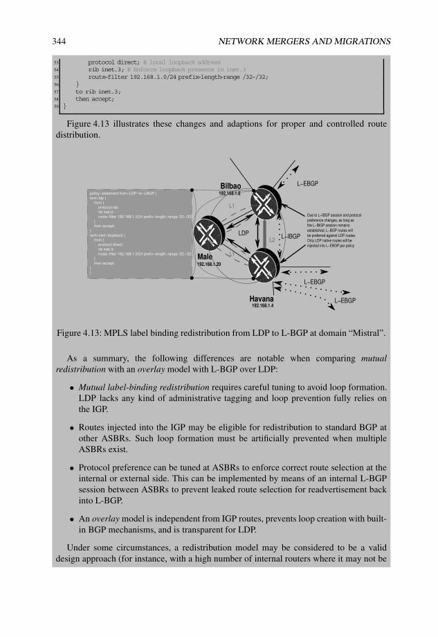
344 NETWORK MERGERS AND MIGRATIONS
53 protocol direct; # local loopback address54 rib inet.3; # Enforce loopback presence in inet.355 route-filter 192.168.1.0/24 prefix-length-range /32-/32;56 }57 to rib inet.3;58 then accept;59 }
Figure 4.13 illustrates these changes and adaptions for proper and controlled routedistribution.
ution.
Male
Bilbao
Havana192.168.1.4
192.168.1.20
192.168.1.8
L1
L1
L−EBGP
L−EBGP
L−EBGP
LDP
policy−statement from−LDP−to−LBGP {
term ldp {
from {
protocol ldp;
rib inet.3;
route−filter 192.168.1.0/24 prefix−length−range /32−/32;
}
then accept;
}
term own−loopback {
from {
protocol direct;
rib inet.3;
route−filter 192.168.1.0/24 prefix−length−range /32−/32;
}
then accept;
}
}
Due to L−IBGP session and protocol
preference changes, as long as
the L−IBGP session remains
established, L−BGP routes will
be preferred against LDP routes.
Only LDP native routes will be
injected into L−EBGP per policy
L−IBGPL2
Figure 4.13: MPLS label binding redistribution from LDP to L-BGP at domain “Mistral”.
As a summary, the following differences are notable when comparing mutualredistribution with an overlay model with L-BGP over LDP:
• Mutual label-binding redistribution requires careful tuning to avoid loop formation.LDP lacks any kind of administrative tagging and loop prevention fully relies onthe IGP.
• Routes injected into the IGP may be eligible for redistribution to standard BGP atother ASBRs. Such loop formation must be artificially prevented when multipleASBRs exist.
• Protocol preference can be tuned at ASBRs to enforce correct route selection at theinternal or external side. This can be implemented by means of an internal L-BGPsession between ASBRs to prevent leaked route selection for readvertisement backinto L-BGP.
• An overlay model is independent from IGP routes, prevents loop creation with built-in BGP mechanisms, and is transparent for LDP.
Under some circumstances, a redistribution model may be considered to be a validdesign approach (for instance, with a high number of internal routers where it may not be
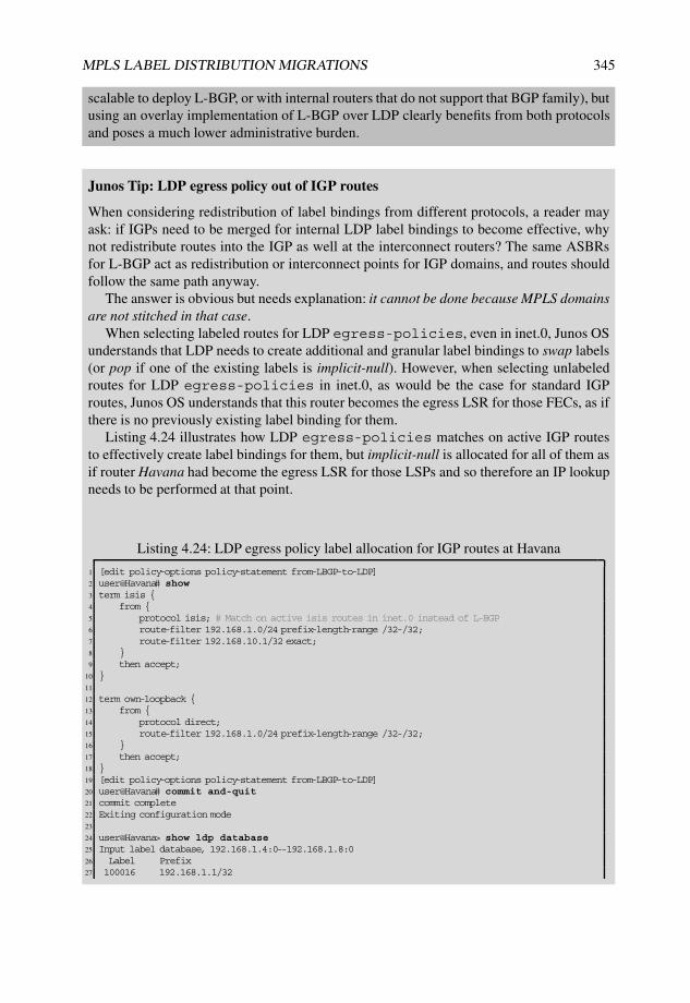
MPLS LABEL DISTRIBUTION MIGRATIONS 345
scalable to deploy L-BGP, or with internal routers that do not support that BGP family), butusing an overlay implementation of L-BGP over LDP clearly benefits from both protocolsand poses a much lower administrative burden.
Junos Tip: LDP egress policy out of IGP routes
When considering redistribution of label bindings from different protocols, a reader mayask: if IGPs need to be merged for internal LDP label bindings to become effective, whynot redistribute routes into the IGP as well at the interconnect routers? The same ASBRsfor L-BGP act as redistribution or interconnect points for IGP domains, and routes shouldfollow the same path anyway.
The answer is obvious but needs explanation: it cannot be done because MPLS domainsare not stitched in that case.
When selecting labeled routes for LDP egress-policies, even in inet.0, Junos OSunderstands that LDP needs to create additional and granular label bindings to swap labels(or pop if one of the existing labels is implicit-null). However, when selecting unlabeledroutes for LDP egress-policies in inet.0, as would be the case for standard IGProutes, Junos OS understands that this router becomes the egress LSR for those FECs, as ifthere is no previously existing label binding for them.
Listing 4.24 illustrates how LDP egress-policies matches on active IGP routesto effectively create label bindings for them, but implicit-null is allocated for all of them asif router Havana had become the egress LSR for those LSPs and so therefore an IP lookupneeds to be performed at that point.
Listing 4.24: LDP egress policy label allocation for IGP routes at Havana
1 [edit policy-options policy-statement from-LBGP-to-LDP]2 user@Havana# show3 term isis {4 from {5 protocol isis; # Match on active isis routes in inet.0 instead of L-BGP6 route-filter 192.168.1.0/24 prefix-length-range /32-/32;7 route-filter 192.168.10.1/32 exact;8 }9 then accept;
10 }11
12 term own-loopback {13 from {14 protocol direct;15 route-filter 192.168.1.0/24 prefix-length-range /32-/32;16 }17 then accept;18 }19 [edit policy-options policy-statement from-LBGP-to-LDP]20 user@Havana# commit and-quit21 commit complete22 Exiting configuration mode23
24 user@Havana> show ldp database25 Input label database, 192.168.1.4:0--192.168.1.8:026 Label Prefix27 100016 192.168.1.1/32

346 NETWORK MERGERS AND MIGRATIONS
28 100016 192.168.1.2/3229 <...>30
31 Output label database, 192.168.1.4:0--192.168.1.8:032 Label Prefix # PHP for all FECs33 3 192.168.1.1/3234 3 192.168.1.2/3235 3 192.168.1.3/3236 3 192.168.1.4/3237 3 192.168.1.5/3238 3 192.168.1.6/3239 3 192.168.1.7/3240 3 192.168.1.8/3241 3 192.168.1.9/3242 3 192.168.1.10/3243 3 192.168.1.20/3244 3 192.168.1.21/3245 3 192.168.10.1/3246
47 Input label database, 192.168.1.4:0--192.168.1.20:048 Label Prefix49 299792 192.168.1.1/3250 299792 192.168.1.2/3251 <...>52
53 Output label database, 192.168.1.4:0--192.168.1.20:054 Label Prefix55 3 192.168.1.1/3256 3 192.168.1.2/3257 3 192.168.1.3/3258 3 192.168.1.4/3259 3 192.168.1.5/3260 3 192.168.1.6/3261 3 192.168.1.7/3262 3 192.168.1.8/3263 3 192.168.1.9/3264 3 192.168.1.10/3265 3 192.168.1.20/3266 3 192.168.1.21/3267 3 192.168.10.1/32
4.5.5 Stage two: Labeled BGP deployment over RSVP-TE in domain“Cyclone”
Domain “Cyclone” is an RSVP-TE fully meshed LSP setup with full-blown TE extensionsavailable. As per the original requirements and design decisions, it will be interconnectedto domain “Mistral” via external L-BGP to advertise internal and receive external labelbindings. Also, internal L-BGP is implemented in an overlay fashion, resolving over RSVP-TE LSPs.
Fundamentally, the main difference with the previous integration at domain “Mistral”(Section 4.5.4) is the resolution substrate for internal L-BGP: LDP at domain “Mistral”,RSVP-TE at domain “Cyclone”.
Because of the downstream-on-demand nature of RSVP-TE, a full mesh of participatingdevices is required when internal L-BGP is deployed. This is needed to ensure completeconnectivity and resolution, and the need becomes more obvious than with LDP (which usesdownstream-unsolicited propagation).

MPLS LABEL DISTRIBUTION MIGRATIONS 347
Therefore, internal L-BGP is rolled out in domain “Cyclone” in a parallel fashion, bysimply extending the new labeled-unicast family over the existing BGP full mesh andlocally creating a label binding for the own loopback to be advertised in L-BGP.
Because this domain also includes two ASBRs with external L-BGP, the labeled-unicast family also needs to be externally activated towards domain “Mistral” and otherrouters.
In a symmetric fashion to the activation on router Bilbao illustrated in Listing 4.15,Listing 4.25 describes the configuration at router Skopie. As with the previous case, inet.3is configured as the primary table to install L-BGP routes only in inet.3 and without anycopies in inet.0 (see Lines 9 and 22).
Listing 4.25: Complete BGP configuration and rib-groups at Skopie
1 user@Skopie# show2 [edit protocols bgp]3 group IBGP {4 type internal;5 local-address 192.168.1.2;6 family inet {7 labeled-unicast {8 rib {9 inet.3; # inet.3 as primary table
10 }11 }12 }13 export [ nhs own-loopback ]; # next hop self policy for IBGP routes14 neighbor 192.168.1.6; # Internal full BGP mesh15 neighbor 192.168.1.7;16 neighbor 192.168.1.21;17 }18 group EBGP {19 family inet {20 labeled-unicast {21 rib {22 inet.3; # inet.3 as primary table23 }24 }25 }26 export own-loopback;27 neighbor 172.16.1.1 {28 peer-as 64503;29 }30 }31
32 [edit policy-options policy-statement own-loopback]33 user@Skopie# show34 term own-loopback {35 from {36 protocol direct; # local loopback address37 rib inet.3; # Enforce loopback presence in inet.338 route-filter 192.168.1.0/24 prefix-length-range /32-/32;39 }40 to rib inet.3;41 then accept;42 }43
44 [edit routing-options]45 user@Skopie# show46 interface-routes {47 rib-group inet int-to-inet3; # Apply rib-groups to direct routes48 }49 static {50 route 172.16.0.0/12 {51 next-hop 172.26.26.1;

348 NETWORK MERGERS AND MIGRATIONS
52 retain;53 no-readvertise;54 }55 }56 rib-groups {57 int-to-inet3 {58 import-rib [ inet.0 inet.3 ]; # inet.0 as primary, inet.3 as secondary59 import-policy interface-to-inet3; # Route sharing controlled by import policy60 }61 direct {62 import-rib [ inet.0 inet.3 ];63 }64 }65 router-id 192.168.1.2;66 autonomous-system 64501;67
68 [edit policy-options policy-statement interface-to-inet3]69 user@Skopie# show70 term loopback {71 from interface lo0.0; # Just match on loopback address72 then accept;73 }74 term no-more-inet3 {75 to rib inet.3;76 then reject; # Do not import anything else into inet.377 }78 term default {79 to rib inet.0;80 then accept; # allow default accept for primary table inet.081 }
Likewise, routers from domain “Cyclone” include rib-groups applied to their ownloopback address for leaking into inet.3 (Line 57), being tailored with a rib-groupimport-policy (Line 59), and export policies for all BGP neighbors to advertise thethe router’s own label bindings (Lines 13 and 26).
Therefore, internal L-BGP resolves this time thanks to RSVP-TE acting as underlyingMPLS label distribution protocol, but similarly to domain “Mistral”, BGP routes remainunpreferred because of default protocol preferences. Listing 4.26 shows the inet.3 table withall internal routes from domain “Cyclone”. Some observations are worth mentioning here:
• L-BGP routes remain inactive due to route preference against RSVP-TE (Lines 15, 28,and 41).
• All L-BGP loopback bindings from router Livorno, router Barcelona and routerHonolulu are implicit-null (Lines 17, 30, and 43).
• All L-BGP routes resolve over the underlying RSVP-TE LSPs, requiring a labelpush with the RSVP-TE allocated label, except for router Livorno which is directlyconnected and considers implicit-null for RSVP-TE (Lines 14, 26, and 39).
Listing 4.26: Internal L-BGP routes inactive resolving over RSVP-TE at router Skopie
1 user@Skopie> show route table inet.3 extensive |2 match “entr|AS:|reason|Next-hop|Label|Preference”3 192.168.1.2/32 (1 entry, 1 announced)4 *Direct Preference: 05 Next-hop reference count: 36 Local AS: 645017 192.168.1.6/32 (2 entries, 2 announced)8 *RSVP Preference: 7

MPLS LABEL DISTRIBUTION MIGRATIONS 349
9 Next-hop reference count: 410 Label-switched-path Skopie-to-Livorno11 Local AS: 6450112 BGP Preference: 170/-10113 Next-hop reference count: 214 Label-switched-path Skopie-to-Livorno # Resolving over RSVP-TE15 Inactive reason: Route Preference16 Local AS: 64501 Peer AS: 6450117 Route Label: 318 192.168.1.7/32 (2 entries, 2 announced)19 *RSVP Preference: 720 Next-hop reference count: 421 Label-switched-path Skopie-to-Barcelona22 Label operation: Push 30076823 Local AS: 6450124 BGP Preference: 170/-10125 Next-hop reference count: 226 Label-switched-path Skopie-to-Barcelona # Resolving over RSVP-TE27 Label operation: Push 30076828 Inactive reason: Route Preference29 Local AS: 64501 Peer AS: 6450130 Route Label: 331 192.168.1.21/32 (2 entries, 2 announced)32 *RSVP Preference: 733 Next-hop reference count: 434 Label-switched-path Skopie-to-Honolulu35 Label operation: Push 30131236 Local AS: 6450137 BGP Preference: 170/-10138 Next-hop reference count: 239 Label-switched-path Skopie-to-Honolulu # Resolving over RSVP-TE40 Label operation: Push 30131241 Inactive reason: Route Preference42 Local AS: 64501 Peer AS: 6450143 Route Label: 3
Such internal label bindings need to be exchanged with other routers from differentdomains. The same route resolution concept for L-BGP needs to be evaluated for externalinterconnects, meaning that these routes need to be exchanged over MPLS-enabled inter-faces.
All external interconnects from domain “Cyclone” are single-hop L-EBGP with norequirement for indirect resolution in inet.3. Thus, in this setup, activating the externalinterface for MPLS is enough, together with the new family over the EBGP session.Listing 4.27 illustrates that simple activation for the case of router Skopie.
Listing 4.27: External MPLS activation for L-EBGP at router Skopie
1 [edit protocols mpls]2 user@Skopie# set interface so-0/1/0.0 # External interface activation into MPLS3
4 [edit interfaces]5 user@Skopie# set so-0/1/0.0 family mpls # Family mpls active on external interface
Figure 4.14 illustrates the L-BGP overlay model over the RSVP-TE full mesh in thedomain.
What If... Redistribution of RSVP-TE and L-BGP in domain “Cyclone”
At this stage, it is worth evaluating whether mutual redistribution between RSVP-TE andL-BGP label bindings could be a feasible alternative.

350 NETWORK MERGERS AND MIGRATIONS
The main limitation is imposed by the different nature of label distribution with eachprotocol: downstream on-demand in the case of RSVP-TE and downstream unsolicited inthe case of L-BGP.
While FECs need to be statically configured on each RSVP-TE LSP on each ingressLSR for path signaling to occur, L-BGP populates label bindings in an unsolicited fashionfollowing the standard BGP distribution rules.
It is possible to extract RSVP-TE label bindings and inject them into L-BGP at theASBR that is acting as ingress LSR for the RSVP-TE LSP. But how could other LSRs forthose LSPs be aware of L-BGP label bindings present at the ASBRs? Each LSR wouldhave to be configured with the FECs of existing or new LSPs, either for mapping to anexisting LSP or for a downstream on-demand solicitation for new labels for each newerFEC. Mapping additional FECs over a joint RSVP-TE LSP can be achieved in Junos OSby means of the install knob.
However, this alternative clearly does not scale in a realistic scenario as soon as thesetup requires multiple FECs.
Another option would be to deploy LDP for downstream unsolicited label distributionin an overlay fashion with RSVP-TE, using LDP tunneling techniques, and then to performredistribution between LDP and L-BGP. This concept has a basic design flaw, because L-BGP can already be extended inside the domain in such an overlay manner without needingto introduce another protocol just for redistribution purposes.
Skopie
Livorno
Barcelona
Honolulu
192.168.1.2
192.168.1.6
192.168.1.7
192.168.1.21Area 0.0.0.0
TE extensions
Link failure
RSVP−TE
Full meshL−EBGP
L−EBGP
L−EBGP
policy−statement from−RSVP−LDP−to−LBGP {
term ldp {
from {
protocol ldp;
rib inet.3;
route−filter 192.168.1.0/24 prefix−length−range /32−/32;
}
then accept;
}
/* output skipped */
}
L−IBGP
policy−statement own−loopback {
term own−loopback {
from {
protocol direct;
rib inet.3;
route−filter 192.168.1.0/24 prefix−length−range /32−/32;
}
then accept;
}
}
L−IBGP
L−IBGP
L−IBGP
L−IBGP
Figure 4.14: Stage two: internal L-BGP over RSVP-TE at domain “Cyclone”.
Junos Tip: Installing a secondary loopback address for RSVP-TE
Junos OS offers resources for manipulating route installation on an existing LSP for FECsrepresented by addresses different from the RSVP-TE destination itself.

MPLS LABEL DISTRIBUTION MIGRATIONS 351
Listing 4.28 illustrates the configuration of the install knob to attachadditional prefixes as eligible FECs beyond a certain RSVP-TE LSP and theno-install-to-address feature to avoid installing the LSP end point itself,which is done for clarity purposes.
When Junos OS installs additional destinations over a common RSVP-TE LSP, metricsfor the LSP egress end are inherited by all other prefixes, which aligns with the purpose ofanother parallel loopback identification with the same routing reachability.
Listing 4.28: LSP FEC installation migration to a secondary loopback for the LSP toBarcelona in Livorno
1 [edit protocols mpls label-switched-path Livorno-to-Barcelona]2 user@Livorno# show3 no-install-to-address;4 to 192.168.1.7;5 install 192.168.1.77/32;6
7 user@Livorno> show route table inet.3 192.168.1.78
9 inet.3: 11 destinations, 16 routes (10 active, 0 holddown, 1 hidden)10 + = Active Route, - = Last Active, * = Both11
12 192.168.1.7/32 *[LDP/9] 00:00:44, metric 10 # RSVP backup path has disappeared13 > to 172.16.1.53 via ge-0/2/0.014
15 user@Livorno> show route table inet.3 192.168.1.7716
17 inet.3: 11 destinations, 16 routes (10 active, 0 holddown, 1 hidden)18 + = Active Route, - = Last Active, * = Both19
20 192.168.1.77/32 *[RSVP/10] 00:00:49, metric 10 # RSVP LSP preferred for the secondary address21 > to 172.16.1.53 via ge-0/2/0.0, label-switched-path Livorno-to-Barcelona22
23 user@Livorno> show mpls lsp name Livorno-to-Barcelona extensive24 Ingress LSP: 3 sessions25
26 192.168.1.727 From: 192.168.1.6, State: Up, ActiveRoute: 0, LSPname: Livorno-to-Barcelona28 ActivePath: (primary)29 LoadBalance: Random30 Encoding type: Packet, Switching type: Packet, GPID: IPv431 *Primary State: Up, Preference: 1032 Priorities: 7 033 SmartOptimizeTimer: 18034 Computed ERO (S [L] denotes strict [loose] hops): (CSPF metric: 10)35 172.16.1.53 S36 Received RRO (ProtectionFlag 1=Available 2=InUse 4=B/W 8=Node 10=SoftPreempt 20=Node-ID):37 172.16.1.5338 16 Sep 20 19:20:55.959 CSPF: computation result accepted 172.16.1.5339 15 Sep 20 17:24:18.289 Selected as active path40 14 Sep 20 17:24:18.288 Record Route: 172.16.1.5341 13 Sep 20 17:24:18.288 Up42 <...>
Note that installation of the additional FEC for the secondary address and removal of theroute for the primary end point has been entirely graceful, without the need to tear downthe path.
At this point, MPLS services and applications could be migrated over secondaryaddresses. For instance, setting MP-BGP sessions among those secondary addressesautomatically provides RSVP-TE inherent features for the BGP families over thesesessions.

352 NETWORK MERGERS AND MIGRATIONS
4.5.6 Stage three: Labeled BGP interconnect between domain“Cyclone” and domain “Mistral”
At this point, external L-BGP sessions are activated on router Bilbao and router Havana asASBRs for domain “Mistral”, and router Skopie and router Livorno as ASBRs for domain“Cyclone”.
Router Havana and router Bilbao have two direct interconnects over different links andonce these inter-AS sessions become established, label bindings from each domain areflooded inside the other.
The cornerstone of this migration methodology is visible here as a specific behaviorin Junos OS: despite being inactive paths, L-BGP routes are advertised externally andMPLS label actions are programmed in the forwarding plane. Without requiring furthermanipulation, MPLS label actions derived from L-BGP are prepared and L-BGP routes areadvertised over the external sessions.
Listing 4.29 shows how internal label bindings from router Havana, as ASBR for domain“Mistral”, are advertised to router Livorno, and how label swap actions are programmed forthe various labels. For instance, Lines 6, 26, and 36 show how the L-BGP label allocated forrouter Bilbao is advertised by router Havana, programmed in the forwarding table of routerHavana as a swap action towards router Male, and presented as a pop action in router Maletowards router Bilbao, respectively.
Listing 4.29: L-BGP routes advertised from Havana to Livorno
1 user@Havana> show route advertising-protocol bgp 172.16.1.38 extensive2 | match “entr|Label”3 * 192.168.1.4/32 (1 entry, 1 announced) # Havana4 Route Label: 35 192.168.1.8/32 (2 entries, 2 announced) # Bilbao6 Route Label: 2999527 192.168.1.20/32 (2 entries, 2 announced) # Male8 Route Label: 2999369
10 user@Havana> show route table mpls label 29993611
12 mpls.0: 16 destinations, 16 routes (16 active, 0 holddown, 0 hidden)13 + = Active Route, - = Last Active, * = Both14
15 299936 *[VPN/170] 00:19:28, metric2 100, from 192.168.1.20 # Pop towards Male16 > to 172.16.1.85 via ge-1/1/0.0, Pop17 299936(S=0) *[VPN/170] 00:19:28, metric2 100, from 192.168.1.2018 > to 172.16.1.85 via ge-1/1/0.0, Pop19
20
21 user@Havana> show route table mpls label 29995222
23 mpls.0: 16 destinations, 16 routes (16 active, 0 holddown, 0 hidden)24 + = Active Route, - = Last Active, * = Both25
26 299952 *[VPN/170] 00:20:14, metric2 743, from 192.168.1.20 # Swap to Bilbao27
28 > to 172.16.1.85 via ge-1/1/0.0, Swap 29977629
30
31 user@male-re0> show route table mpls label 29977632
33 mpls.0: 7 destinations, 7 routes (7 active, 0 holddown, 0 hidden)34 + = Active Route, - = Last Active, * = Both35
36 299776 *[LDP/9] 00:16:08, metric 1 # Pop to Bilbao37 > via so-3/2/1.0, Pop

MPLS LABEL DISTRIBUTION MIGRATIONS 353
38 299776(S=0) *[LDP/9] 00:16:08, metric 139 > via so-3/2/1.0, Pop
At domain “Cyclone”, a similar behavior can be observed, with the main difference beingan underlying resolution substrate of single-hop RSVP-TE LSPs.
Listing 4.30 shows how internal label bindings from router Livorno, an ASBR for domain“Cyclone”, are advertised to router Havana. Because these internal single-hop RSVP-TELSPs are used for internal system reachability, all MPLS forwarding actions related toexternally advertised label bindings result in a label pop and next-hop selection to each ofthese RSVP-TE LSPs when forwarding traffic internally.
Lines 17, 27, and 37 show the respective next hop installed for each of the advertisedlabels for router Skopie, router Barcelona, and router Livorno with the consequence of alabel pop action and selection of the corresponding RSVP-TE LSP.
Listing 4.30: L-BGP routes advertised from Livorno to Havana
1 user@Livorno> show route advertising-protocol bgp 172.16.1.37 extensive2 | match “entr|Label”3 192.168.1.2/32 (2 entries, 2 announced)4 Route Label: 3016005 * 192.168.1.6/32 (1 entry, 1 announced)6 Route Label: 37 192.168.1.7/32 (2 entries, 2 announced)8 Route Label: 3016169 192.168.1.21/32 (2 entries, 2 announced)
10 Route Label: 30166411
12 user@Livorno> show route table mpls label 30160013
14 mpls.0: 23 destinations, 23 routes (23 active, 0 holddown, 0 hidden)15 + = Active Route, - = Last Active, * = Both16
17 301600 *[VPN/170] 00:33:49, metric2 64, from 192.168.1.2 # Pop to Skopie18 > via so-0/0/0.0, label-switched-path Livorno-to-Skopie19 301600(S=0) *[VPN/170] 00:33:49, metric2 64, from 192.168.1.220 > via so-0/0/0.0, label-switched-path Livorno-to-Skopie21
22 user@Livorno> show route table mpls label 30161623
24 mpls.0: 23 destinations, 23 routes (23 active, 0 holddown, 0 hidden)25 + = Active Route, - = Last Active, * = Both26
27 301616 *[VPN/170] 00:33:56, metric2 10, from 192.168.1.7 # Pop to Barcelona28 > to 172.16.1.53 via ge-0/2/0.0, label-switched-path Livorno-to-Barcelona29 301616(S=0) *[VPN/170] 00:33:56, metric2 10, from 192.168.1.730 > to 172.16.1.53 via ge-0/2/0.0, label-switched-path Livorno-to-Barcelona31
32 user@Livorno> show route table mpls label 30166433
34 mpls.0: 23 destinations, 23 routes (23 active, 0 holddown, 0 hidden)35 + = Active Route, - = Last Active, * = Both36
37 301664 *[VPN/170] 00:34:03, metric2 10, from 192.168.1.21 # Pop to Honolulu38 > to 172.16.1.90 via ge-1/3/0.0, label-switched-path Livorno-to-Honolulu39 301664(S=0) *[VPN/170] 00:34:03, metric2 10, from 192.168.1.2140 > to 172.16.1.90 via ge-1/3/0.0, label-switched-path Livorno-to-Honolulu
At this point, it is interesting to analyze how the externally advertised label bindings fromeach domain are internally distributed at the other and which label actions are programmedfor each of them.

354 NETWORK MERGERS AND MIGRATIONS
Listing 4.31 illustrates how externally received label bindings are internally propagatedwith a label swap action, showing an example for the label corresponding to router Barcelona(Line 29).
Listing 4.31: L-BGP routes received at Havana from Livorno
1 user@Havana> show route receive-protocol bgp 172.16.1.38 extensive | match “entr|Label”2 * 192.168.1.2/32 (3 entries, 1 announced)3 Route Label: 3016004 * 192.168.1.6/32 (3 entries, 1 announced)5 Route Label: 36 * 192.168.1.7/32 (3 entries, 1 announced)7 Route Label: 3016168 * 192.168.1.21/32 (3 entries, 1 announced)9 Route Label: 301664
10
11 user@Havana> show route advertising-protocol bgp 192.168.1.20 extensive12 | match “entr|Label”13 * 192.168.1.2/32 (3 entries, 1 announced)14 Route Label: 29987215 * 192.168.1.4/32 (1 entry, 1 announced)16 Route Label: 317 * 192.168.1.6/32 (3 entries, 1 announced)18 Route Label: 29988819 * 192.168.1.7/32 (3 entries, 1 announced)20 Route Label: 29990421 * 192.168.1.21/32 (3 entries, 1 announced)22 Route Label: 29992023
24 user@Havana> show route table mpls label 29990425
26 mpls.0: 16 destinations, 16 routes (16 active, 0 holddown, 0 hidden)27 + = Active Route, - = Last Active, * = Both28
29 299904 *[VPN/170] 00:46:2030 > to 172.16.1.38 via so-1/0/0.0, Swap 301616 # Swap external with internal label
Listing 4.32 shows the same behavior on router Livorno, considering a label swap action,shown here for the label corresponding to router Bilbao (Line 26).
Listing 4.32: L-BGP routes received at Havana from Livorno
1 user@Livorno> show route receive-protocol bgp 172.16.1.37 extensive2 | match “entr|Label”3 * 192.168.1.4/32 (3 entries, 1 announced)4 Route Label: 35 * 192.168.1.8/32 (3 entries, 1 announced)6 Route Label: 2999527 * 192.168.1.20/32 (3 entries, 1 announced)8 Route Label: 2999369
10 user@Livorno> show route advertising-protocol bgp 192.168.1.7 extensive11 | match “entr|Label”12 * 192.168.1.4/32 (3 entries, 1 announced)13 Route Label: 30168014 * 192.168.1.6/32 (1 entry, 1 announced)15 Route Label: 316 * 192.168.1.8/32 (3 entries, 1 announced)17 Route Label: 30171218 * 192.168.1.20/32 (3 entries, 1 announced)19 Route Label: 30169620
21 user@Livorno> show route table mpls label 30171222
23 mpls.0: 23 destinations, 23 routes (23 active, 0 holddown, 0 hidden)24 + = Active Route, - = Last Active, * = Both25

MPLS LABEL DISTRIBUTION MIGRATIONS 355
26 301712 *[VPN/170] 00:49:1127 > to 172.16.1.37 via so-0/0/1.0, Swap 299952 # Swap external with internal label
Label-binding advertisements and end-to-end flows between router Barcelona and routerBilbao from previous listings in this stage are summarized in Figure 4.15 with labelscorresponding to each protocol for router Barcelona, and Figure 4.16 for router Bilbao. Bothfigures also include MPLS label actions programmed in the forwarding plane.
MaleBilbao Havana Livorno Barcelona192.168.1.4192.168.1.20192.168.1.8 192.168.1.6 192.168.1.7
RSVP−TELDPLDP
L−IBGP L−IBGP L−EBGP L−IBGP
Route Reflector
No Next Hop self
for client routes
Domain "Mistral" Domain "Cyclone"
299840
299904 301616
3LDP RSVP−TE
L−BGPL−BGP
Pop
No label change
with no next hop self
Swap
L−BGP label with LDP label
Pop
VPN label
Label Advertisement
Forwarding
3299904
3
Figure 4.15: Stage three: label bindings for router Barcelona.
Junos Tip: Troubleshooting an L-BGP overlay model with inter-AS Option C
Once domains have been interconnected, Layer 3 VPNs can be extended over them simplyby establishing multihop external BGP sessions directly among the PEs or by using routereflectors. In a nutshell, this is an implementation of the inter-AS Option C model as definedin [RFC4364] and explained later in Section 5.2.6.
As a simple example, an extended L3VPN is configured with common RouteDistinguisher (RD) and Route Target (RT) on both router Bilbao and router Barcelona,as shown in Listing 4.33 for router Bilbao.
When establishing such a simple L3VPN for troubleshooting purposes, the followingitems are relevant:
• Reachability routes for EBGP peers also need to be present in inet.0 to establish theBGP session itself. This is achieved by means of rib-groups to copy primaryinet.3 routes into inet.0 as well (Line 17).

356 NETWORK MERGERS AND MIGRATIONS
MaleBilbao Havana Livorno Barcelona192.168.1.4192.168.1.20192.168.1.8 192.168.1.6 192.168.1.7
RSVP−TELDPLDP
L−IBGP L−IBGP L−EBGP L−IBGP
Route Reflector
No Next Hop self
for client routes
Domain "Mistral" Domain "Cyclone"
3
3 3
299776
299952
3
301712
LDP RSVP−TE
L−BGPL−BGP
Pop
No label change
with no next hop self
Swap L−BGP label
with LDP label
Swap L−EBGP label
with L−IBGP label
VPN label
Label Advertisement
Forwarding
Figure 4.16: Stage three: label bindings for router Bilbao.
• L3VPNs are established over multihop EBGP sessions with extended TTL values(Line 30). Other designs may consider domain ASBRs as route reflectors forfamily inet-vpn unicast.
• A triple MPLS label push action takes place at the ingress for the VPN label,L-BGP remote neighbor reachability label, and LDP internal ASBR reachability label(Line 51).
Listing 4.33: Layer 3 VPN over MPLS interconnect between Barcelona and Bilbao
1 [edit routing-instances NMM]2 user@Bilbao-re0# show3 instance-type vrf;4 interface lo0.8;5 route-distinguisher 65401:65401;6 vrf-target target:65401:65401;7 vrf-table-label;8
9 [edit protocols bgp]10 user@Bilbao-re0# show11 group IBGP {12 type internal;13 local-address 192.168.1.8;14 family inet {15 unicast;16 labeled-unicast {17 rib-group optc; # Needed to set up extended EBGP inet-vpn session18 rib {19 inet.3;20 }

MPLS LABEL DISTRIBUTION MIGRATIONS 357
21 }22 }23 export [ nhs own-loopback ];24 neighbor 192.168.1.20;25 }26 <...>27 group EBGP-l3vpn {28 type external;29 multihop {30 ttl 5; # extended ttl31 }32 local-address 192.168.1.8;33 family inet-vpn {34 unicast;35 }36 peer-as 64501;37 neighbor 192.168.1.7;38 }39
40 [edit routing-options rib-groups optc]41 user@Bilbao-re0# show42 import-rib [ inet.3 inet.0 ]; # Copy inet.3 routes into inet.043
44 user@Bilbao-re0> show route table NMM45
46 NMM.inet.0: 2 destinations, 2 routes (2 active, 0 holddown, 0 hidden)47 + = Active Route, - = Last Active, * = Both48
49 192.168.7.7/32 *[BGP/170] 00:15:32, localpref 100, from 192.168.1.750 AS path: 64501 I51 > via so-1/3/1.0, Push 301824, Push 299904, Push 299840(top) # Triple push52 192.168.8.8/32 *[Direct/0] 00:41:5953 > via lo0.854
55 user@Bilbao-re0> ping 192.168.7.7 source 192.168.8.8 routing-instance NMM56 PING 192.168.7.7 (192.168.7.7): 56 data bytes57 64 bytes from 192.168.7.7: icmp_seq=0 ttl=64 time=1.190 ms58 64 bytes from 192.168.7.7: icmp_seq=1 ttl=64 time=1.111 ms59 C60 --- 192.168.7.7 ping statistics ---61 2 packets transmitted, 2 packets received, 0% packet loss62 round-trip min/avg/max/stddev = 1.111/1.151/1.190/0.039 ms
4.5.7 Stage four: Redundant label binding distribution over domain“Monsoon”
Despite not being MPLS-enabled, the leased lines over domain “Monsoon” provide an alter-native and redundant interconnect path between domain “Cyclone” and domain “Mistral”.In fact, router Nantes is strategically positioned simply to interconnect both domains locallywithout a specific need to extend any MPLS label distribution protocol inside the domain“Monsoon”.
One virtue of an external L-BGP is that it can easily provide a redundant label distributionpath that is completely independent of any IGP interconnect. LDP cannot be used tointerconnect such domains at this stage, because the IGPs are not linked yet and RSVP-TErequires specific FEC installation which is not really intended in this transit label distributionscenario. Just by activating MPLS and external L-BGP from this AS, another interconnectbetween domain “Cyclone” and domain “Mistral” is automatically enabled.
Figure 4.17 shows a simplified form of this scenario. Listing 4.34 shows the neces-sary configuration steps at this dual connection, together with representative outputs for

358 NETWORK MERGERS AND MIGRATIONS
Nantes10.10.1.1
Torino
10.10.1.9
InvernessBasel
10.10.1.3
10.10.1.10
NSSA no−summaries 0.0.0.3
Area 0.0.0.0
OSPFv2
192.168.1.1
No internal MPLS
label distribution protocol
L−EBGPL−EBGP
Skopie192.168.1.2
Bilbao192.168.1.8
AS64502
AS64503
AS64501
MPLS label binding propagation from L−IBGP to L−EBGP and viceversa.
Standard BGP attribute handling
Standard EBGP next−hop rewrite
and label swap action as MPLS
interconnect
Figure 4.17: Stage four: MPLS interconnect via external L-BGP at domain “Monsoon”.
exchanged routes. Note that MPLS actions are also programmed. The general action isan MPLS label swap, except for directly connected L-EBGP neighbors with implicit-nulladvertisements, as per Lines 132 for router Bilbao and 124 for router Skopie, which showthat a label pop is installed in the Forwarding Engine.
Listing 4.34: MPLS interconnect between domain “Mistral” and domain “Cyclone” viaNantes
1 [edit protocols bgp]2 user@Nantes# show3 group L-EBGP {4 type external;5 family inet {6 labeled-unicast {7 rib {8 inet.3;9 }
10 }11 }12 export own-loopback;13 neighbor 172.16.1.5 {14 peer-as 64502;15 }16 neighbor 172.16.1.2 {17 peer-as 64501;18 }19 }20
21 [edit protocols mpls] # External interfaces active for mpls protocols22 user@Nantes# show23 interface so-0/1/0.0;24 interface ge-1/3/0.0;25
26 [edit interfaces so-0/1/0 unit 0]27 user@Nantes# show28 family inet {29 address 172.16.1.1/30;30 }

MPLS LABEL DISTRIBUTION MIGRATIONS 359
31 family iso;32 family mpls; # active for external interconnect33
34 [edit interfaces ge-1/3/0 unit 0]35 user@Nantes# show36 family inet {37 address 172.16.1.6/30;38 }39 family iso;40 family mpls; # active for external interconnect41
42 user@Nantes> show bgp summary43 Groups: 1 Peers: 2 Down peers: 044 Table Tot Paths Act Paths Suppressed History Damp State Pending45 inet.3 14 7 0 0 0 046 Peer AS InPkt OutPkt OutQ Flaps Last Up/Dwn State|#Active/Received/
Accepted/Damped...47 172.16.1.2 64501 4046 4053 0 1 1d 6:22:45 Establ48 inet.3: 4/7/7/049 172.16.1.5 64502 3316 3322 0 0 1d 0:47:05 Establ50 inet.3: 3/7/7/051
52
53 # Received from domain ‘‘Cyclone’’54 user@Nantes> show route receive-protocol bgp 172.16.1.2 extensive | match “entr|Label”55 * 192.168.1.2/32 (2 entries, 1 announced)56 Route Label: 357 192.168.1.4/32 (2 entries, 1 announced)58 Route Label: 30169659 * 192.168.1.6/32 (2 entries, 1 announced)60 Route Label: 30112061 * 192.168.1.7/32 (2 entries, 1 announced)62 Route Label: 30115263 192.168.1.8/32 (2 entries, 1 announced)64 Route Label: 30172865 192.168.1.20/32 (2 entries, 1 announced)66 Route Label: 30171267 * 192.168.1.21/32 (2 entries, 1 announced)68 Route Label: 30150469
70 # Received from domain ‘‘Mistral’’71 user@Nantes> show route receive-protocol bgp 172.16.1.5 extensive | match “entr|Label”72 192.168.1.2/32 (2 entries, 1 announced)73 Route Label: 30188874 * 192.168.1.4/32 (2 entries, 1 announced)75 Route Label: 30184076 192.168.1.6/32 (2 entries, 1 announced)77 Route Label: 30185678 192.168.1.7/32 (2 entries, 1 announced)79 Route Label: 30187280 * 192.168.1.8/32 (2 entries, 1 announced)81 Route Label: 382 * 192.168.1.20/32 (2 entries, 1 announced)83 Route Label: 30126484 192.168.1.21/32 (2 entries, 1 announced)85 Route Label: 30190486
87
88 # Advertised to domain ‘‘Cyclone’’89 user@Nantes> show route advertising-protocol bgp 172.16.1.2 extensive |90 match “entr|Label”91 * 192.168.1.1/32 (1 entry, 1 announced)92 Route Label: 393 * 192.168.1.4/32 (2 entries, 1 announced)94 Route Label: 31014495 * 192.168.1.8/32 (2 entries, 1 announced)96 Route Label: 30982497 * 192.168.1.20/32 (2 entries, 1 announced)98 Route Label: 309840

360 NETWORK MERGERS AND MIGRATIONS
99
100
101 # Advertised to domain ‘‘Mistral’’102 user@Nantes> show route advertising-protocol bgp 172.16.1.5 extensive |103 match “entr|Label”104 * 192.168.1.1/32 (1 entry, 1 announced)105 Route Label: 3106 * 192.168.1.2/32 (2 entries, 1 announced)107 Route Label: 309696108 * 192.168.1.6/32 (2 entries, 1 announced)109 Route Label: 309744110 * 192.168.1.7/32 (2 entries, 1 announced)111 Route Label: 309760112 * 192.168.1.21/32 (2 entries, 1 announced)113 Route Label: 310032114
115 user@Nantes> show route table mpls.0116
117 mpls.0: 12 destinations, 12 routes (12 active, 0 holddown, 0 hidden)118 + = Active Route, - = Last Active, * = Both119
120 <...>121 309696 *[VPN/170] 1d 00:50:29 # Skopie (directly connected)122 > to 172.16.1.2 via so-0/1/0.0, Pop123 309696(S=0) *[VPN/170] 1d 00:50:29 # Skopie (directly connected)124 > to 172.16.1.2 via so-0/1/0.0, Pop125 309744 *[VPN/170] 1d 00:50:29 # Livorno126 > to 172.16.1.2 via so-0/1/0.0, Swap 301120127 309760 *[VPN/170] 1d 00:50:29 # Barcelona128 > to 172.16.1.2 via so-0/1/0.0, Swap 301152129 309824 *[VPN/170] 1d 00:50:29 # Bilbao (directly connected)130 > to 172.16.1.5 via ge-1/3/0.0, Pop131 309824(S=0) *[VPN/170] 1d 00:50:29 # Bilbao (directly connected)132 > to 172.16.1.5 via ge-1/3/0.0, Pop133 309840 *[VPN/170] 1d 00:50:29 # Male134 > to 172.16.1.5 via ge-1/3/0.0, Swap 301264135 310032 *[VPN/170] 09:50:07 # Honolulu136 > to 172.16.1.2 via so-0/1/0.0, Swap 301504137 310144 *[VPN/170] 02:04:56 # Havana138 > to 172.16.1.5 via ge-1/3/0.0, Swap 301840
4.5.8 Stage five: MPLS integration and interconnect via router Lille
Router Lille is the collocated router at the NOC premises, and one initial objective is to beable to integrate it into the existing MPLS services from both domain “Cyclone” and domain“Mistral”.
L-BGP provides resources to enable this additional interconnect between the two domainsand, at the same time, to activate label bindings from each IGP in a completely independentfashion. For instance, L3VPN CEs requiring specific monitoring from the NOC or SLAmeasurement devices based on RPM are directly reachable from the NOC even beforeintegrating IGPs!
This exercise is parallel to the setup configured on router Nantes based on external L-BGP.However, there are two important remarks:
• Router Lille is configured with a global AS, 65500, maintaining EBGP sessionstowards both domains.
• Router Lille not only reflects routes between both interconnected domains (with third-party next hops as is standard in broadcast segments), but also advertises its ownloopback so that it is present in both domains.

MPLS LABEL DISTRIBUTION MIGRATIONS 361
This second bullet is fundamental for the instantiation and integration of MPLS appli-cations. The advertisement of the own loopback address as L-BGP route is achieved in thesame fashion as with other ASBRs: by leaking the loopback address into inet.3 and enablingadvertisement from there with the rib-groups structure.
Listing 4.35 depicts configuration changes and the outputs of the two BGP sessionstowards each domain.
Listing 4.35: MPLS interconnect between domain “Mistral” and domain “Cyclone” and ownintegration at Lille
1 [edit protocols bgp]2 user@Lille# show3 group L-EBGP {4 family inet {5 labeled-unicast {6 rib {7 inet.3;8 }9 }
10 }11 export own-loopback;12 neighbor 172.16.100.1 { # Havana13 peer-as 64502;14 }15 neighbor 172.16.100.8 { # Livorno16 peer-as 64501;17 }18 }19
20 [edit policy-options policy-statement own-loopback]21 user@Lille# show22 term own-loopback {23 from {24 protocol direct;25 rib inet.3;26 route-filter 192.168.1.0/24 prefix-length-range /32-/32;27 }28 then accept;29 }30
31 [edit policy-options policy-statement interface-to-inet3]32 user@Lille# show33 term loopback {34 from interface lo0.0; # Leak only loopback address to inet.335 then accept;36 }37 term no-more-inet3 {38 to rib inet.3;39 then reject;40 }41 term default {42 to rib inet.0;43 then accept;44 }45
46 [edit protocols mpls]47 user@Lille# show48 interface fe-0/3/0.0; # Activate external interface on MPLS49
50 [edit interfaces fe-0/3/0]51 user@Lille# show52 unit 0 {53 family inet {54 address 172.16.100.5/24;55 }56 family iso;

362 NETWORK MERGERS AND MIGRATIONS
57 family mpls;58 }59
60 user@Lille> show bgp summary61 Groups: 1 Peers: 2 Down peers: 062 Table Tot Paths Act Paths Suppressed History Damp State Pending63 inet.0 0 0 0 0 0 064 inet.3 13 9 0 0 0 065 Peer AS InPkt OutPkt OutQ Flaps Last Up/Dwn State|#Active/Received/Damped
...66 172.16.100.1 64503 1286 1304 0 4 9:14:53 Establ67 inet.3: 3/4/068 172.16.100.8 64501 1028 1029 0 3 7:44:59 Establ69 inet.3: 5/8/070
71 user@Lille> show route advertising-protocol bgp 172.16.100.172
73 inet.3: 9 destinations, 16 routes (9 active, 0 holddown, 0 hidden)74 Prefix Nexthop MED Lclpref AS path75 * 192.168.1.2/32 Self 64501 I # Skopie76 * 192.168.1.5/32 Self I # Lille77 * 192.168.1.6/32 Self 64501 I # Livorno78 * 192.168.1.7/32 Self 64501 I # Barcelona79 * 192.168.1.21/32 Self 64501 I # Honolulu80
81 user@Lille> show route advertising-protocol bgp 172.16.100.882
83 inet.3: 9 destinations, 16 routes (9 active, 0 holddown, 0 hidden)84 Prefix Nexthop MED Lclpref AS path85 * 192.168.1.4/32 Self 64502 I # Havana86 * 192.168.1.5/32 Self I # Lille87 * 192.168.1.8/32 Self 64502 I # Bilbao88 * 192.168.1.20/32 Self 64502 I # Male89
90
91 user@Lille> show route receive-protocol bgp 172.16.100.1 table inet.392
93 inet.3: 9 destinations, 13 routes (9 active, 0 holddown, 0 hidden)94 Prefix Nexthop MED Lclpref AS path95 * 192.168.1.4/32 172.16.100.1 64503 I # Havana96 192.168.1.6/32 172.16.100.1 64503 64501 I # Livorno97 * 192.168.1.8/32 172.16.100.1 743 64503 I # Bilbao98 * 192.168.1.20/32 172.16.100.1 100 64503 I # Male
Figure 4.18 depicts the interconnect setup through router Lille.
Junos Tip: L-BGP route selection due to “Active preferred”
Whenever router Lille is interconnected, a label binding for 192.168.1.5 is receivedfrom both peers and populated further, indicating that router Lille has been alreadyinterconnected to router Havana and router Livorno.
Both routes are received at router Nantes by means of different EBGP sessions fromrouters with different router IDs. Under these circumstances, router ID comparison is notperformed by default in Junos OS if one of the external paths is active. As describedin Section 3.2.8, given that both different external paths are usable and have the samepreference, with same local preference, AS path lengths, origin, MED, IGP metric, andempty cluster lists, Junos OS enforces a certain last active path behavior in this caseto avoid persistent route oscillation that can result from MED comparison, which canpotentially lead to best-path selection loops in given scenarios.

MPLS LABEL DISTRIBUTION MIGRATIONS 363
Havana Livorno192.168.1.4 192.168.1.6
Lille192.168.1.5
IS−IS and LDP
domain "Mistral"
AS64502
OSPFv2 and RSVP−TE
domain "Cyclone"
AS64501
NOC mgmt
center
AS65500
L−EBGP
L−EBGP
LDP
Standard EBGP next−hop rewrite
and label swap action as MPLS
interconnect
Advertisement of own loopback
to both domains
RSVP−TE
Full
mesh
L−IBGP
RR client
L−IBGP
L−IBGP
L−IBGP
Figure 4.18: Stage five: MPLS integration and interconnect via router Lille.
Listing 4.36 shows how both versions of L-BGP route for 192.168.1.5 are evaluated andillustrates that the final tie-breaking item is whether the route was previously active, asshown in Line 30.
Listing 4.36: L-BGP route selection for Lille at Nantes
1 user@Nantes> show route 192.168.1.5/32 exact extensive table inet.32
3 inet.3: 10 destinations, 18 routes (10 active, 0 holddown, 0 hidden)4 192.168.1.5/32 (2 entries, 1 announced)5 TSI:6 Page 0 idx 0 Type 1 val 8cfb0d87 *BGP Preference: 170/-1018 Next hop type: Router9 Next-hop reference count: 2
10 Source: 172.16.1.211 Next hop: 172.16.1.2 via so-0/1/0.0, selected12 Label operation: Push 30174413 State: <Active Ext>14 Local AS: 64503 Peer AS: 6450115 Age: 2:01:4716 Task: BGP_64501.172.16.1.2+6338717 Announcement bits (1): 1-BGP RT Background18 AS path: 64501 65500 I19 Accepted20 Route Label: 30174421 Localpref: 10022 Router ID: 192.168.1.223 BGP Preference: 170/-10124 Next hop type: Router25 Next-hop reference count: 126 Source: 172.16.1.527 Next hop: 172.16.1.5 via ge-1/3/0.0, selected28 Label operation: Push 30193629 State: <Ext>30 Inactive reason: Active preferred # Unselected31 Local AS: 64503 Peer AS: 6450232 Age: 2:01:4133 Task: BGP_64502.172.16.1.5+55450
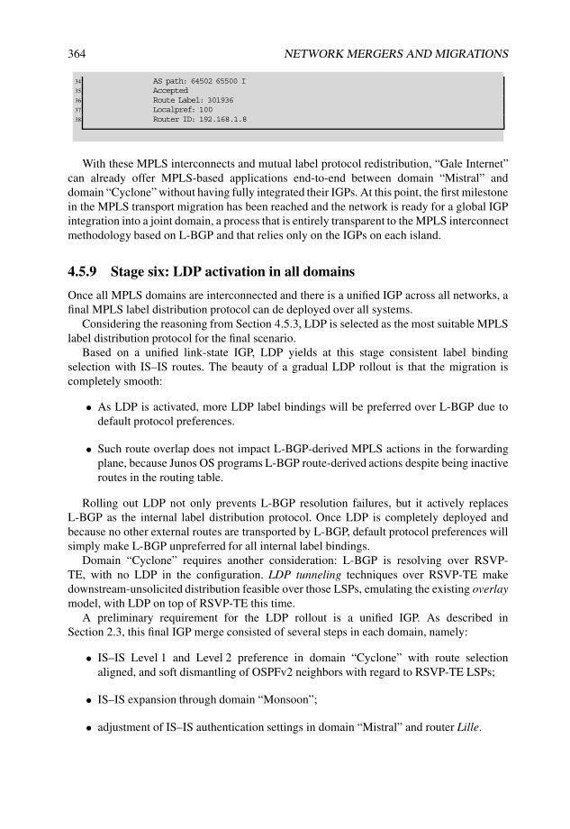
364 NETWORK MERGERS AND MIGRATIONS
34 AS path: 64502 65500 I35 Accepted36 Route Label: 30193637 Localpref: 10038 Router ID: 192.168.1.8
With these MPLS interconnects and mutual label protocol redistribution, “Gale Internet”can already offer MPLS-based applications end-to-end between domain “Mistral” anddomain “Cyclone” without having fully integrated their IGPs. At this point, the first milestonein the MPLS transport migration has been reached and the network is ready for a global IGPintegration into a joint domain, a process that is entirely transparent to the MPLS interconnectmethodology based on L-BGP and that relies only on the IGPs on each island.
4.5.9 Stage six: LDP activation in all domains
Once all MPLS domains are interconnected and there is a unified IGP across all networks, afinal MPLS label distribution protocol can de deployed over all systems.
Considering the reasoning from Section 4.5.3, LDP is selected as the most suitable MPLSlabel distribution protocol for the final scenario.
Based on a unified link-state IGP, LDP yields at this stage consistent label bindingselection with IS–IS routes. The beauty of a gradual LDP rollout is that the migration iscompletely smooth:
• As LDP is activated, more LDP label bindings will be preferred over L-BGP due todefault protocol preferences.
• Such route overlap does not impact L-BGP-derived MPLS actions in the forwardingplane, because Junos OS programs L-BGP route-derived actions despite being inactiveroutes in the routing table.
Rolling out LDP not only prevents L-BGP resolution failures, but it actively replacesL-BGP as the internal label distribution protocol. Once LDP is completely deployed andbecause no other external routes are transported by L-BGP, default protocol preferences willsimply make L-BGP unpreferred for all internal label bindings.
Domain “Cyclone” requires another consideration: L-BGP is resolving over RSVP-TE, with no LDP in the configuration. LDP tunneling techniques over RSVP-TE makedownstream-unsolicited distribution feasible over those LSPs, emulating the existing overlaymodel, with LDP on top of RSVP-TE this time.
A preliminary requirement for the LDP rollout is a unified IGP. As described inSection 2.3, this final IGP merge consisted of several steps in each domain, namely:
• IS–IS Level 1 and Level 2 preference in domain “Cyclone” with route selectionaligned, and soft dismantling of OSPFv2 neighbors with regard to RSVP-TE LSPs;
• IS–IS expansion through domain “Monsoon”;
• adjustment of IS–IS authentication settings in domain “Mistral” and router Lille.

MPLS LABEL DISTRIBUTION MIGRATIONS 365
All these events occur in a completely transparent fashion with regard to the current MPLStransport topology. External L-BGP sessions are set on a single-hop basis and existing LDPand RSVP-TE domains are internal (the IS–IS setup keeps the same forwarding paths asOSPFv2 in domain “Cyclone”).
After aligning all protocol preferences and natively activating IS–IS Level 2 in the domaininterconnects, the setup is ready for LDP activation.
Junos Tip: Unadvertised effects of LDP-IGP Synchronization when stitching domains
LDP-IGP Synchronization is considered to be a best practice in networks with MPLSservices and IP reachability completely aligned. For this reason, it is part of the standardconfiguration at many networks to activate that feature in templates or via Junos OSgroups. However, there is an obvious but dramatic pitfall if LDP-IGP Synchronizationis not taken into account when stitching domains.
Once the final IGP has been completely rolled out, LDP can be smoothly activated inall domain interconnects, assuming that LDP neighbor router identifiers are known throughthe IGP. If this LDP activation stage is needed beforehand and LDP–IGP synchronizationis active, the feature may indirectly maximize the IGP metric for the interconnect link, eventhough the IGP adjacency is legitimate, if router IDs are not known between peers and theLDP session over TCP cannot be established.
This condition means that pre-activating LDP in those interconnect cases is harmlesswith regard to LDP because the session is not set up until the IGP is standardizedand the router identifiers are reachable. However, if the IGP interface includes theldp-synchronization knob, the collateral effect is a topology change.
Consider the interconnect case between router Skopie and router Nantes, which canestablish a Level 2 IS–IS adjacency between them. Router Nantes is still the ASBR for theold OSPFv2 domain and is using the old non-public loopback address (which also acts,by default, as the LDP router identifier). Although IS–IS can be perfectly activated with aproper Net-ID and family iso activation in the interconnect, enabling LDP in this casewith LDP-IGP synchronization indirectly leads to link-cost maximization. Activating LDPunder these circumstances over a fully established and sane IS–IS adjacency changes theSPF tree across all domains!
Listing 4.37 summarizes the circumstances and effects on both router Skopie and routerNantes. Lines 13, 26, and 29 show standard IS–IS derived metrics in the respective old andnew-style TLVs. At the moment LDP is activated and because of the TCP connection errorfor the LDP session, as seen in Line 64, metric values are maximized for the neighbor IS inold and new-style TLVs, as shown in Lines 92, 105, and 109 and the metric value remainsmaximum until the situation with LDP is corrected. Note, however, that the metric valuefor the related IP prefix over that interface is immune to this modification, because thefeature affects only neighbor reachability, as seen in Lines 107 and 110 when compared tothe previous status in Lines 27 and 30.
Listing 4.37: Indirect effects of LDP-IGP synchronization with unknown LDP routeridentifier
1 user@Skopie> show isis adjacency2 Interface System L State Hold (secs) SNPA3 so-0/1/0.0 Nantes 2 Up 23

366 NETWORK MERGERS AND MIGRATIONS
4 so-1/0/0.0 Livorno 2 Up 255
6 user@Skopie> show isis interface so-0/1/0.0 extensive7 IS-IS interface database:8 so-0/1/0.09 Index: 67, State: 0x6, Circuit id: 0x1, Circuit type: 2
10 LSP interval: 100 ms, CSNP interval: 15 s, Loose Hello padding11 Adjacency advertisement: Advertise12 Level 213 Adjacencies: 1, Priority: 64, Metric: 643 # Standard calculated metric14 Hello Interval: 9.000 s, Hold Time: 27 s15
16 user@Skopie> show isis database Nantes extensive17 | match “IP router id|Skopie|172.16.1.0/30”18 IS neighbor: Skopie.00 Metric: 16019 IP prefix: 172.16.1.0/30 Metric: 160 Internal Up20 IP router id: 10.10.1.121 IS extended neighbor: Skopie.00, Metric: default 16022 IP extended prefix: 172.16.1.0/30 metric 160 up23
24 user@Skopie> show isis database Skopie extensive25 | match “IP router id|Nantes|172.16.1.0/30”26 IS neighbor: Nantes.00 Metric: 643 # Standard derived metric27 IP prefix: 172.16.1.0/30 Metric: 643 Internal Up # Standard derived
metric28 IP router id: 192.168.1.229 IS extended neighbor: Nantes.00, Metric: default 643 # Standard derived metric30 IP extended prefix: 172.16.1.0/30 metric 643 up # Standard derived metric31
32 # Activating LDP over interconnect interface with LDP-IGP Synchronization33
34 user@Skopie> configure35 Entering configuration mode36 [edit]37 user@Skopie# set protocols isis interface so-0/1/0.0 ldp-synchronization38 [edit]39 user@Skopie# set protocols ldp interface so-0/1/0.040 [edit]41 user@Skopie# commit and-quit42 commit complete43 Exiting configuration mode44
45 user@Skopie> show isis adjacency46 Interface System L State Hold (secs) SNPA47 so-0/1/0.0 Nantes 2 Up 2648 so-1/0/0.0 Livorno 2 Up 2549
50 user@Skopie> show ldp neighbor51 Address Interface Label space ID Hold time52 192.168.1.6 lo0.0 192.168.1.6:0 3253 192.168.1.7 lo0.0 192.168.1.7:0 3154 192.168.1.21 lo0.0 192.168.1.21:0 4355 172.16.1.1 so-0/1/0.0 10.10.1.1:0 10 # Neighbor detected56
57 user@Skopie> show ldp session 10.10.1.1 extensive58 Address: 10.10.1.1, State: Nonexistent, Connection: Closed, Hold time: 059 Session ID: 192.168.1.2:0--10.10.1.1:060 Connection retry in 0 seconds61 Active, Maximum PDU: 4096, Hold time: 30, Neighbor count: 162 Neighbor types: discovered # Discovered neighbor over interface63 Keepalive interval: 10, Connect retry interval: 164 Last down 00:00:00 ago; Reason: connection error # TCP connection error65 Protection: disabled66 Local - Restart: disabled, Helper mode: enabled67 Remote - Restart: disabled, Helper mode: disabled68 Local maximum neighbor reconnect time: 120000 msec69 Local maximum neighbor recovery time: 240000 msec70 Nonstop routing state: Not in sync

MPLS LABEL DISTRIBUTION MIGRATIONS 367
71 Next-hop addresses received:72 so-0/1/0.073
74 Message type Total Last 5 seconds75 Sent Received Sent Received76 Initialization 0 0 0 077 Keepalive 0 0 0 078 Notification 0 0 0 079 Address 0 0 0 080 Address withdraw 0 0 0 081 <...>82
83 user@Skopie> show isis interface so-0/1/0.0 extensive84 IS-IS interface database:85 so-0/1/0.086 Index: 67, State: 0x6, Circuit id: 0x1, Circuit type: 287 LSP interval: 100 ms, CSNP interval: 15 s, Loose Hello padding88 Adjacency advertisement: Advertise89 LDP sync state: in hold-down, for: 00:00:06, reason: LDP down during config90 config holdtime: infinity91 Level 292 Adjacencies: 1, Priority: 64, Metric: 16777214 # Maximized cost93 Hello Interval: 9.000 s, Hold Time: 27 s94
95 user@Skopie> show isis database Nantes extensive |96 match “IP router id|Skopie|172.16.1.0/30”97 IS neighbor: Skopie.00 Metric: 16098 IP prefix: 172.16.1.0/30 Metric: 160 Internal Up99 IP router id: 10.10.1.1
100 IS extended neighbor: Skopie.00, Metric: default 160101 IP extended prefix: 172.16.1.0/30 metric 160 up102
103 user@Skopie> show isis database Skopie extensive |104 match “IP router id|Nantes|172.16.1.0/30”105 IS neighbor: Nantes.00 Metric: 16777214 # Maximized metric for neighbor106 IP prefix: 172.16.1.0/30 Metric: 643 Internal Up107 # Standard derived metric for IP prefix108 IP router id: 192.168.1.2109 IS extended neighbor: Nantes.00, Metric: default 16777214 # Maximized metric for neighbor110 IP extended prefix: 172.16.1.0/30 metric 643 up # Standard derived metric for IP prefix
Activating LDP over the interconnects requires adding them under the LDP protocolstanza. These interfaces are already present under [edit protocols mpls] andinclude family mpls in their definition, which was done earlier when external L-BGPwas activated.
By enabling LDP, the implicit discovery mechanism is enabled over those links to identifyneighbors for potential LDP sessions. For those systems in domain “Cyclone”, there is notgoing to be any internal auto-discovery but rather, targeted LDP sessions on top of RSVP-TELSPs. LDP is tunneled in that case over all internal RSVP-TE LSPs.
As a representative example, Listing 4.38 depicts the results of activating LDP over theinterconnect and of tunneling LDP over RSVP-TE LSPs on router Livorno. It is worth makingthese observations:
• L-BGP routes do not disappear, but become unpreferred after the newer LDP paths areestablished.
• LDP routes point to the same peer as the previous L-BGP label bindings (Lines 52, 58,62, 67, and 72).

368 NETWORK MERGERS AND MIGRATIONS
• Label actions derived from L-BGP remain, and only newly allocated labels for LDPappear in the MPLS table.
• Despite being inactive now, L-BGP routes are exported to external EBGP neighborswith the same labels (Line 77).
This last bullet is key for a seamless migration: the same advertised label bindings inlabeled BGP persist despite the fact that the paths are locally inactive. This is a powerfulmigration feature because gradual rollout of LDP activation remains transparent for L-BGProute advertisements.
Listing 4.38: LDP activation in Livorno
1 user@Livorno> show route table inet.3 terse2
3 inet.3: 10 destinations, 23 routes (9 active, 0 holddown, 1 hidden)4 + = Active Route, - = Last Active, * = Both5
6 A Destination P Prf Metric 1 Metric 2 Next hop AS path7 * 192.168.1.1/32 B 170 100 >so-0/0/0.0 64503 I # Preferred BGP route for
Nantes8 B 170 100 >172.16.1.37 64502 64503 I9 B 170 100 >172.16.100.1 64502 64503 I
10 B 170 100 >172.16.100.5 65500 64502 64503 I11 <...>12 * 192.168.1.4/32 B 170 100 >172.16.1.37 64502 I # Preferred BGP route for
Havana13 B 170 100 >172.16.100.1 64502 I14 B 170 100 >172.16.100.5 65500 64502 I15 * 192.168.1.5/32 B 170 100 >172.16.100.5 65500 I # Preferred BGP route for
Lille16 B 170 100 >172.16.1.37 64502 65500 I17 B 170 100 >172.16.100.1 64502 65500 I18 <...>19 * 192.168.1.8/32 B 170 100 >172.16.1.37 64502 I # Preferred BGP route for
Bilbao20 B 170 100 >172.16.100.1 64502 I21 B 170 100 >172.16.100.5 65500 64502 I22 * 192.168.1.20/32 B 170 100 >172.16.1.37 64502 I # Preferred BGP route for
Male23 B 170 100 >172.16.100.1 64502 I24 B 170 100 >172.16.100.5 65500 64502 I25 <...>26
27 # Activating LDP over interconnect and RSVP-TE LSPs28
29 [edit]30 user@Livorno# show | compare31 [edit protocols mpls label-switched-path Livorno-to-Skopie]32 + ldp-tunneling;33 [edit protocols mpls label-switched-path Livorno-to-Barcelona]34 + ldp-tunneling;35 [edit protocols mpls label-switched-path Livorno-to-Honolulu]36 + ldp-tunneling;37 [edit protocols]38 + ldp {39 + track-igp-metric;40 + strict-targeted-hellos;41 + interface so-0/0/1.0;42 + interface fe-0/3/0.0;43 + interface lo0.0;44 + }45
46 user@Livorno> show route table inet.3 terse47

MPLS LABEL DISTRIBUTION MIGRATIONS 369
48 inet.3: 16 destinations, 38 routes (12 active, 5 holddown, 6 hidden)49 + = Active Route, - = Last Active, * = Both50
51 A Destination P Prf Metric 1 Metric 2 Next hop AS path52 * 192.168.1.1/32 L 9 1386 >so-0/0/1.0 # New LDP route for Nantes53 B 170 100 >so-0/0/0.0 64503 I54 B 170 100 >172.16.1.37 64502 64503 I55 B 170 100 >172.16.100.1 64502 64503 I56 B 170 100 >172.16.100.5 65500 64502 64503 I57 <...>58 * 192.168.1.4/32 L 9 1000 >172.16.100.1 # New LDP route for Havana59 B 170 100 >172.16.1.37 64502 I60 B 170 100 >172.16.100.1 64502 I61 B 170 100 >172.16.100.5 65500 64502 I62 * 192.168.1.5/32 L 9 1000 >172.16.100.5 # New LDP route for Lille63 B 170 100 >172.16.100.5 65500 I64 B 170 100 >172.16.1.37 64502 65500 I65 B 170 100 >172.16.100.1 64502 65500 I66 <...>67 * 192.168.1.8/32 L 9 1743 >172.16.100.1 # New LDP route for Bilbao68 B 170 100 >172.16.1.37 64502 I69 B 170 100 >172.16.100.1 64502 I70 B 170 100 >172.16.100.5 65500 64502 I71 <...>72 * 192.168.1.20/32 L 9 1100 >172.16.100.1 # New LDP route for Male73 B 170 100 >172.16.1.37 64502 I74 B 170 100 >172.16.100.1 64502 I75 B 170 100 >172.16.100.5 65500 64502 I76
77 # Same L-BGP routes advertised78 user@Livorno> show route advertising-protocol bgp 172.16.1.37 extensive |79 match “entr|Label”80 192.168.1.1/32 (6 entries, 3 announced)81 Route Label: 30184082 192.168.1.2/32 (4 entries, 3 announced)83 Route Label: 30185684 192.168.1.5/32 (4 entries, 2 announced)85 Route Label: 30172886 * 192.168.1.6/32 (1 entry, 1 announced)87 Route Label: 388 192.168.1.7/32 (4 entries, 3 announced)89 Route Label: 30209690 192.168.1.21/32 (4 entries, 3 announced)91 Route Label: 301792
This transition on router Livorno is illustrated in Figure 4.19.To summarize, LDP can be gracefully rolled out over all existing routers in the topology.
Once all routers are fully integrated with LDP as domain-wide MPLS label distributionprotocol, the labeled-unicast family from BGP sessions, together with supportingrib-groups for route sharing, can be safely dismantled.
As explained in Section 3.2.3, note that the removal of a given family from an existingBGP session triggers a renegotiation with the newly available address families.
Junos Tip: Knob strict-targeted-hellos and direct LDP sessions
Note that the configuration at domain “Cyclone” routers includes the strict-targeted-hellos knob as an additional protection mechanism against undesiredtargeted LDP sessions, as well as direct LDP sessions over the external interconnects inthe ASBRs. Listing 4.39 reviews the LDP protocol configuration on router Skopie.
The strict-targeted-hellos knob does not restrict LDP sessions to be targetedonly. It actually enforces that all extended targeted LDP sessions to be set up correspond to

370 NETWORK MERGERS AND MIGRATIONS
locally configured RSVP-TE destinations with the ldp-tunneling extension. However,this knob allows direct non-extended LDP sessions to be established over directlyconnected interfaces perfectly. The actions of this knob do not counteract the establishmentof autodiscovered LDP sessions; the knob simply enforces constraints to LDP targetedsessions.
Listing 4.39: LDP configuration at Skopie including strict-targeted-hellos
1 user@Skopie> show configuration protocols ldp2 strict-targeted-hellos;3 egress-policy from-LBGP-to-LDP;4 interface so-0/1/0.0;5 interface lo0.0;
Havana Livorno192.168.1.4 192.168.1.6
Lille192.168.1.5
IS−IS and LDP
domain "Mistral"
AS64502
OSPFv2 and RSVP−TE
domain "Cyclone"
AS64501
NOC mgmt
center
AS65500
L−EBGP
L−EBGP
LDP
Auto−discovered interface−based
LDP sessions on external
interconnects
LDP tunneling over RSVP−TE LSPs
on internal domain
RSVP−TE
Full
mesh
L−IBGP
RR client
L−IBGP
L−IBGP
L−IBGP
LDP
LDP
Targeted
LDP
sessions
Figure 4.19: Stage six: activation of LDP in router Livorno as gradual label distributiontransition.
4.5.10 Migration summary
Figure 4.20 summarizes the goals of the migration scenario after the integration has beencompleted.
The MPLS label distribution protocol migration has had several dependencies on the IGPand BGP migrations, but first by interconnecting and later transitioning the MPLS labeldistribution protocols, the new features have been gradually deployed in a seamless fashion.
All prerequisites have been satisfied, first to expedite the MPLS service offering acrossall domains and later to unify the setup with a common internal MPLS label distributionprotocol.
“Gale Internet” has been able to expand their service portfolio with extended reachabilitywhile in the middle of a merger process, and customers (and obviously top management!)

MPLS LABEL DISTRIBUTION MIGRATIONS 371
Male
Bilbao
Havana
Nantes
Skopie
Livorno
Barcelona
Honolulu
192.168.1.4
192.168.1.20
192.168.1.8
192.168.1.1
192.168.1.2
192.168.1.6
192.168.1.7
192.168.1.21
Torino
Lille
192.168.1.9
Inverness
Basel
192.168.1.5
192.168.1.3
192.168.1.10
Final LDP
domain
Area 0.0.0.0
TE extensions
NOC mgmt
center
Co
st
10
00
LDP
RSVP−TE
LDP
LDP
LDP
LDP tunneling
over RSVP−TE
Targeted LDP sessions
Targeted LDP sessions
Targeted LDP sessions
Targeted LDP sessions
Figure 4.20: Final MPLS label distribution topology.
are impressed by this! This case study has provided several lessons and concepts learned,including the following:
• evaluation of MPLS label distribution to interconnect domains;
• analysis of several MPLS label distribution protocol strategies and dependencies withregard to IGP routes;
• evaluation of route resolution requirements for L-BGP;
• utilization of the rib-groups Junos OS feature for route leaking between inet.3 andinet.0;
• definition of policies to export label bindings for the routers’ own loopback addresseswith L-BGP;
• identification of L-BGP label allocation, incorrect configuration, and route resolutionfailures;
• expansion of L-IBGP inside each domain;
• LDP egress policy adaption to create label bindings for external routes in a mutualprotocol redistribution model;
• analysis of potential scenarios for mutual label binding redistribution on dual-ASBRdomains;
• installation of additional FECs to be bound to existing RSVP-TE LSPs;

372 NETWORK MERGERS AND MIGRATIONS
• rollout of redundant label distribution interconnects among domains;
• identification of MPLS label action differences when announcing internally andexternally L-BGP routes;
• definition of troubleshooting configuration for L3VPNs over L-BGP (Inter-AS OptionC);
• advertisement of label bindings related to inactive L-BGP routes with MPLS labelaction installed in the forwarding plane;
• graceful activation of LDP, allowing other label distribution protocols running in thebackground;
• discovery of unadvertised effects of LDP-IGP synchronization when stitching domains;
• LDP-tunneling deployment over an existing RSVP-TE LSP mesh for downstream-unsolicited label distribution;
• utilization of the strict-targeted-hellos Junos OS feature to enforce con-straints for LDP-tunneled sessions;
• as the final cleanup, gradual decommissioning of L-BGP.
Bibliography
[RFC2702] D. Awduche, J. Malcolm, J. Agogbua, M. O’Dell, and J. McManus. Require-ments for Traffic Engineering Over MPLS. RFC 2702 (Informational),September 1999.
[RFC3035] B. Davie, J. Lawrence, K. McCloghrie, E. Rosen, G. Swallow, Y. Rekhter, andP. Doolan. MPLS using LDP and ATM VC Switching. RFC 3035 (ProposedStandard), January 2001.
[RFC3036] L. Andersson, P. Doolan, N. Feldman, A. Fredette, and B. Thomas. LDPSpecification. RFC 3036 (Proposed Standard), January 2001. Obsoleted byRFC 5036.
[RFC3037] B. Thomas and E. Gray. LDP Applicability. RFC 3037 (Informational),January 2001.
[RFC3107] Y. Rekhter and E. Rosen. Carrying Label Information in BGP-4. RFC 3107(Proposed Standard), May 2001.
[RFC3209] D. Awduche, L. Berger, D. Gan, T. Li, V. Srinivasan, and G. Swallow. RSVP-TE: Extensions to RSVP for LSP Tunnels. RFC 3209 (Proposed Standard),December 2001. Updated by RFCs 3936, 4420, 4874, 5151, 5420.
[RFC3212] B. Jamoussi, L. Andersson, R. Callon, R. Dantu, L. Wu, P. Doolan, T. Worster,N. Feldman, A. Fredette, M. Girish, E. Gray, J. Heinanen, T. Kilty, andA. Malis. Constraint-Based LSP Setup using LDP. RFC 3212 (ProposedStandard), January 2002. Updated by RFC 3468.

MPLS LABEL DISTRIBUTION MIGRATIONS 373
[RFC3468] L. Andersson and G. Swallow. The Multiprotocol Label Switching (MPLS)Working Group decision on MPLS signaling protocols. RFC 3468 (Informa-tional), February 2003.
[RFC3936] K. Kompella and J. Lang. Procedures for Modifying the Resource reSerVationProtocol (RSVP). RFC 3936 (Best Current Practice), October 2004.
[RFC4090] P. Pan, G. Swallow, and A. Atlas. Fast Reroute Extensions to RSVP-TE forLSP Tunnels. RFC 4090 (Proposed Standard), May 2005.
[RFC4203] K. Kompella and Y. Rekhter. OSPF Extensions in Support of GeneralizedMulti-Protocol Label Switching (GMPLS). RFC 4203 (Proposed Standard),October 2005.
[RFC4205] K. Kompella and Y. Rekhter. Intermediate System to Intermediate System (IS-IS) Extensions in Support of Generalized Multi-Protocol Label Switching(GMPLS). RFC 4205 (Informational), October 2005. Obsoleted by RFC 5307.
[RFC4206] K. Kompella and Y. Rekhter. Label Switched Paths (LSP) Hierarchy withGeneralized Multi-Protocol Label Switching (GMPLS) Traffic Engineering(TE). RFC 4206 (Proposed Standard), October 2005.
[RFC4364] E. Rosen and Y. Rekhter. BGP/MPLS IP Virtual Private Networks (VPNs).RFC 4364 (Proposed Standard), February 2006. Updated by RFCs 4577, 4684.
[RFC5036] L. Andersson, I. Minei, and B. Thomas. LDP Specification. RFC 5036 (DraftStandard), October 2007.
[RFC5151] A. Farrel, A. Ayyangar, and JP. Vasseur. Inter-Domain MPLS and GMPLSTraffic Engineering – Resource Reservation Protocol-Traffic Engineering(RSVP-TE) Extensions. RFC 5151 (Proposed Standard), February 2008.
[RFC5283] B. Decraene, JL. Le Roux, and I. Minei. LDP Extension for Inter-Area LabelSwitched Paths (LSPs). RFC 5283 (Proposed Standard), July 2008.
[RFC5543] H. Ould-Brahim, D. Fedyk, and Y. Rekhter. BGP Traffic EngineeringAttribute. RFC 5543 (Proposed Standard), May 2009.
Further Reading
[1] Ina Minei and Julian Lucek. MPLS-Enabled Applications: Emerging Developments andNew Technologies, June 2008. ISBN 978-0470986448.
[2] Aviva Garrett. JUNOS Cookbook, April 2006. ISBN 0-596-10014-0.
[3] Matthew C. Kolon and Jeff Doyle. Juniper Networks Routers : The Complete Reference,February 2002. ISBN 0-07-219481-2.
[4] James Sonderegger, Orin Blomberg, Kieran Milne, and Senad Palislamovic. JUNOSHigh Availability, August 2009. ISBN 978-0-596-52304-6.
[5] Luc De Ghein. MPLS Fundamentals, December 2006. ISBN 978-1587051975.


5
MPLS Layer 3 VPN Migrations
If MPLS has revolutionized the internetworking industry over the last ten years, BGP-basedLayer 3 VPNs (L3VPNs) are probably their most popular and widespread application. In fact,the ability to construct virtual and independent Layer 3 topologies over the same network ina scalable and flexible fashion and based simply on routing paradigms has been a majorfactor and business driver for many service providers and enterprise networks just to startimplementing MPLS.
A common exercise over the last several years at many internetworks has been a migrationfrom a traditional flat topology to a VPN-structured MPLS environment, not only to offeradditional services but also as a security mechanism or for the sake of controlled and isolatedmanagement at each L3 VPN.
MPLS BGP-based L3VPNs have gained so much popularity that different interconnectmodels have been precluded and evolved over time. These inter-AS interconnect types haveallowed flexible disposition of Layer 3 VPNs across different backbones and providers withmore granular or scalable approaches to stitch them.
[RFC2547] (now evolved to [RFC4364]) started as an appeal to the concept of definingMPLS-based L3VPNs to support the outsourcing of IP backbone services for enterprisenetworks. The idea was to benefit from MPLS features to deploy independent VPNs overthe same global architecture and to have the features be completely separate without a needfor specific security constructs.
BGP-based L3VPNs are based on a so-called peer model, in which Customer Edge (CE)and Provider Edge (PE) devices talk to each other by means of a routing protocol or construct,which can be as simple as mutual static routes or even directly connected networks. Ina nutshell, a unique Route Distinguisher (RD) is added to the prefix information to grantaddress uniqueness, and Route Target (RT) extended communities are also added to it todetermine prefix imports on remote sites. This construct is transported precisely by meansof a AFI 1, SAFI 128 BGP NLRI. The power of this concept resides in the fact that it scalesthe known transport capabilities of BGP, combining the protocol with the MPLS servicemultiplexing premise.
Network Mergers and Migrations Gonzalo Gómez Herrero and Jan Antón Bernal van der Venc© 2010 John Wiley & Sons, Ltd
376 NETWORK MERGERS AND MIGRATIONS
BGP-based L3VPNs have also allowed the construction of multiple any-to-any, one-to-any, or one-to-one VPN communication models simply by defining import and export rulesbased on the RT. Just defining the proper policies is enough to allow or block unidirectionalflows between sites!
Simply by having different routing constructs for each Virtual Routing and Forwarding(VRF) table, a given degree of security is automatically enforced: unless RTs match for bothimport and export policies, there cannot be flows between VRF sites without common RTs(for example, part of a common VPN or extranet). There is no need for additional securityenforcement to achieve this objective, as opposed to traditional security-based VPNs. Thebeauty of this concept is that any security, authentication, or encryption mechanism can beimplemented if needed inside each VPN on top of the isolation provided by BGP-basedMPLS L3 VPNs.
This paradigm also offers the ability to multiplex and differentiate services whenassociated with the L3VPNs. Because several L3VPNs can coexist in the same network,different services can naturally be mapped to different VPNs (either meshed or in arbitraryrelationships) with diverse class-of-service per-hop behaviors or forwarding treatment. JunosOS even offers enough resources to map these L3VPNs to different IGP topologies (thanksto multitopology routing) or to naturally different LSPs, just by setting intended next hops forthese BGP L3VPN NLRIs.
All this flexibility has been the trigger to migrate and integrate legacy and flat networksinto L3VPNs over a common infrastructure and to interconnect them across MPLS back-bones. This chapter deals with the migrations related to MPLS BGP-based L3VPNs, focusingon integrating networks as BGP-based Layer 3 VPNs and migrating through differentinterconnect models.
5.1 Motivations for Layer 3 VPN Migrations
As L3VPNs became more and more popular, the need to interconnect and integrate them soonarose. Ever since [RFC2547], the need to design interconnect mechanisms with protocolartifacts became clear: L3VPNs needed to span beyond a single service provider to beeven more effective than a legacy network. Imagine the operational and installation costsfor a multinational enterprise network being expanded across countries and continents, andcompare them with a L3VPN interconnected across service providers in different regionsthat reuse their infrastructure to offer another VRF termination! Looking at this, how manycorporate customers have major service providers gained over the last years based on thisarchitecture?
When considering the network architectures to be integrated into L3VPNs, several aspectsmust be analyzed, from political reasons to service requirements. As discussed with othertypes of migration, some of these motivations in a real-life scenario may arise individually orin various combinations.
5.1.1 Security enforcement
The ability virtually to segregate Layer 3 topologies over a common infrastructure istremendously powerful. Compared with plain old legacy networks, this separation is natively

MPLS LAYER 3 VPN MIGRATIONS 377
enforced at Layer 3 with the construction of VPNs and the granular definition of RT importand export policies at each VRF.
This segregation can leverage security policies at a given enterprise or service-providingnetwork by implementing an additional native isolation layer between topologies, thatdoes not impede the application of security-based authentication, protection, privacy, orconfidentiality rules among endpoints.
Also, the ability to build up arbitrary communication models enforces certain securitypremises to allow user-to-user communication in each direction.
5.1.2 Communication flow handling
Arbitrary communication models are allowed simply by defining RT import and exportpolicies at each VPN site.
Point-to-multipoint, point-to-point, multipoint-to-multipoint, or any kind of arbitrarymesh can be built up based on RT distribution, and this virtual topology can be administeredand designed independently of routing settings on CE domains or the core backbonetopology.
When integrating a legacy network as a L3VPN, more flexibility in intersite communica-tion can be added with this inherent behavior of L3VPNs, without modifying any previousrouting among internal systems.
5.1.3 Service multiplexing
A key design feature of MPLS is support for multiplexing services within the same networkinfrastructure, mostly on a per-label basis. This feature works not only among different VPNtypes and MPLS applications, but also with diverse L3 VPNs.
The concept of a single L3VPN becomes diffuse when more than one RT can be matchedfor a VRF import or tagged at a VRF export policy. While a L3VPN can be thought of as asubset of sites and site membership is determined by those policies, a VPN-IPv4 route with itsextended communities is the ultimate, deterministic piece of information needed to establishend-to-end flows. The same VPN-IPv4 route can therefore be exported and imported intoseveral L3VPNs, and multiple services from different L3VPNs can thus be multiplexed uponthe same common piece of information.
5.1.4 Route manipulation
By combining an inter-AS connection model with additional constructs, native routes froma VPN can be populated beyond a backbone, constrained within a subset of VRFs, oraggregated at certain VPN boundaries.
This variety of interconnect options provides an added value to a L3VPN when comparedwith a traditional plain network. Routing information can be adapted when stitching L3VPNsback to back or when advertising prefixes out of a VRF (blocking more specific routes, forinstance), independent of the communication protocol between PE and CE.
378 NETWORK MERGERS AND MIGRATIONS
5.1.5 Routing redundancy
VPN-IPv4 uniqueness is determined by the combination of a RD and the internal IPv4prefix. While some routing protocols running in a legacy network just select the best pathfor forwarding purposes, the RD data structure can provide additional identification detailsbound to IPv4 prefixes: VPN-IPv4 routes sharing a common IPv4 prefix can be distinguishedby using alternate RDs.
This fact consumes additional resources but allows quicker convergence for alternate paths(because a backup route is maintained) and grants additional redundancy in failure cases(because the backup route does not need to be readvertised from the original PE).
5.2 Considerations for Layer 3 VPN Migrations
Not only do L3VPNs need to be evaluated for potential technical aspects in migrations, butalso the possible range of protocols to be used to interconnect CE domains with PEs needsto be evaluated, considering both their advantages and drawbacks, particularly in cases inwhich a flat network is being newly integrated as a L3VPN, because such integration alsointroduces changes in the CE domain routing protocol.
Likewise, different interconnect modalities for L3VPNs must be analyzed in terms oftechnical features that offer advantages or pitfalls for integration scenarios.
5.2.1 Layer 3 VPNs
By default, Junos OS assigns an MPLS label to each PE–CE connection and installs thatMPLS route in the respective routing table with a next hop being that logical interface. Also,the VRF-configured RD is assigned to these routes and others received from each site so thatit is attached to these IPv4 prefixes when they are advertised in the form of VPN-IPv4 (orinet-vpn in Junos OS parlance) BGP NLRIs. Note that despite having different routes in thesame VRF, they all share the same common RD. VPN-IPv4 Routes are exported as dictatedby policies that tag them with an arbitrary number of extended communities.
[RFC4360] enforces a given structure on extended communities by defining typesand subtypes, and by allowing them to specify whether they can be transitive acrossAS boundaries. At the time of this writing, IANA has allocated the following standardcommunity types related to L3VPNs as per this recommendation:
• RT (2-octet AS and IPv4-address specific): route-to-VRF membership;
• Router or Site of Origin (2-octet AS and IPv4-address specific): specific site injectingrouting information;
• OSPF Domain Identifier (2-octet AS and IPv4-address specific): OSPF domain forroute-to-LSA translation purposes;
• BGP Data Collection (2-octet AS): standard peer relationship, or geographical ortopological information;
• Source AS (2-octet AS): source AS identifier for C-multicast routes in L3VPNmulticast environments;

MPLS LAYER 3 VPN MIGRATIONS 379
• OSPF Router ID (IPv4-address specific): unique identifier for each instance inside theOSPF domain;
• VRF Route Import (IPv4-address specific): determination for import of C-multicastroutes in a VRF in L3VPN multicast environments;
• OSPF Route Type (Opaque): identification of original OSPF Area, metric, and LSAtype for translation purposes;
• Color Extended Community (Opaque): payload identification related to BGP Encap-sulation SAFI;
• Encapsulation Extended Community (Opaque): encapsulation protocol identifier relatedto BGP Encapsulation SAFI.
RTs ultimately determine how routes are exchanged among VRFs; more specifically, howthey are exported to MP-BGP and to which VRFs IPv4 prefixes are imported from MP-BGP.This process is described in detail in Section 1.2.
PEs sharing a VPN need to exchange those NLRIs, either directly or through any kind ofroute reflector or ASBR. When a PE announces those NLRIs, it can optionally exclude routesfor VPNs not shared with peers thanks to dynamic BGP capabilities related to OutboundRoute Filtering (ORF). Even if this is not done, each PE may receive VPN-IPv4 routes, butonly installs the derived IPv4 prefixes in the per-VRF table if RT policies from the respectiveinstance require their import. These routes need to be valid as well and need to pass all sanitychecks, including BGP next-hop reachability and LSP existence to this endpoint by means ofan MPLS label distribution protocol or a directly connected external peer, so that both MPLSlabels (the outer label for next-hop reachability, and the inner label for the VPN-IPv4 route)are installed in the forwarding plane.
Note that the standard BGP route selection process takes place with VPN-IPv4 routes.Attributes that are used as tie-breakers for path determination are commonly used. Thisbehavior introduces further route selection variables in the case of duplicate routes ormultihoming, such as distributing the IGP metric among PEs or use of local preference, thatwere not previously present in a legacy flat network.
The VRF forwarding table is checked for incoming PE traffic through any CE interfaceto determine whether it must be locally switched towards another CE (in the same oranother VRF that is part of the same VPN, or even the default routing instance with someconfigurations), locally destined to the PE control plane (such as diverse PE–CE routingprotocols), or MPLS-switched to any remote PE. If the destination is remote, both inner andouter MPLS labels are pushed onto the IPv4 packet to be forwarded through the backbone.
The inner VPN label remains untouched in the forwarding path between PEs, and theMPLS backbone switches the outer label as determined by the label distribution protocol.Junos OS performs penultimate-hop popping (PHP) by default, so when a packet reachessuch a hop, the outer label is popped before forwarding the packet to the destination PE. Atthis remote PE, the inner VPN label is matched against the known VRFs and the IPv4 internalpayload is forwarded to the proper CE. In the case of ultimate-hop popping, the destinationPE has to perform all these actions at the same time along with popping the outer label.
Following this review of the natural forwarding and control-plane paths, it is time toconsider additional items when integrating networks by means of BGP-based L3VPNs.

380 NETWORK MERGERS AND MIGRATIONS
Route Distinguisher (RD) selection planning for Layer 3 VPN routes
Route Distinguisher (RD) selection determines address uniqueness.A legacy IPv4 plain topology may not have duplicate addresses. In a VPN-IPv4 setup,
uniqueness is determined by RDs, that are added to the IPv4 prefix, so the risk to overlapaddressing space among VPNs is determined by IPv4 address overlapping and RDs. Despitehaving different RTs, if VPN-IPv4 routes from different VPNs share both RD and IPv4 prefix,they overlap on a route reflector, ASBR, or PE that is importing routes from those VPNs.
A proper network-wide RD allocation scheme yields no overlaps (Junos OS even enforcesa commit error for local duplicate RDs across instances), but CE sites multihomed to differentPEs or VRFs may propagate their internal prefixes in the MPLS cloud with a different or acommon RD.
The tradeoff with RD planning is usually convergence versus memory resource occupa-tion. Having more than a single VPN-IP4 prefix locally representing the same IPv4 prefixwith diverse RDs ensures quicker path selection in case one disappears without requiring aBGP refresh, but comes at the cost of keeping additional memory reserved for all these paths.
RDs can therefore be used to construct multiple VPN-IPv4 routes for the same IPv4 prefix,placing the IPv4 prefix in different VRFs by physically connecting the CE to the VRF orusing route-sharing techniques.
In such fashion, BGP can install multiple different routes to the same end system throughdifferent VPNs, and LSPs to each destination can be implemented by establishing differentpacket-handling or QoS premises. This is certainly one way for differentiating treatment ofdiverse flows towards the same destination.
Route Target (RT) planning for Layer 3 VPN routes
A careful Route Target (RT) plan allows the implementation of any arbitrary virtual topology,leveraging the VPN concept to allow connectivity among different sites in diverse ways.
This use of RTs is considerably more powerful than plain IP networks, because theyallow the crafting of multiple unidirectional flows among arbitrary VRFs without the need toimplement any filtering mechanism.
For instance, the same end system can simultaneously be a CE for different VPNs. It is aquestion of CE routing to the desired attachment circuit to each VRF and then constructing avirtual hub-and-spoke topology with RTs to virtualize access to the same end device throughdifferent VPNs. In this case, filtering or deep packet inspection techniques can be easilyenforced in one VPN, while retaining legacy and plain connections through another.
On the other hand, BGP L3VPNs naturally provide isolation between VPN topologies.Security is enforced by orthogonal VPNs not sharing any kind of RT. Just by keeping controlof VRF import and export policies that match or tag RTs in each direction, differential flowtreatment can be achieved on a per-VPN basis.
BGP next-hop handling for Layer 3 VPN routes
As discussed in Section 3.2.10, the BGP protocol decoupled the physical layer from thecontrol plane by introducing a level of indirection through the protocol next hop. Whenthe reachability information contains MPLS labels, this level of indirection has some

MPLS LAYER 3 VPN MIGRATIONS 381
implications worth exploring for cases in which an intermediate device makes a change tothe next hop.
Figure 5.1 splits the two directions of traffic between the top and bottom halves. The dottedlines correspond to the routing information exchanged over a multiprotocol BGP (MP-BGP)session. Solid lines provide actual MPLS labels used by packets travelling on the forwardingplane.
L1x
L1a
LV21
LV11
LV31
L2r
L1c
L2s
L1d
L1y
L1b
PEPE1
PE1
VPN label
VPN label
BGP session
BGP session
Advertise local−context
VPN label
Tunnel label
Tunnel label
PE2 PE3
PE2 PE3
Figure 5.1: Effect of BGP next-hop change on labeled NLRIs.
The BGP session interconnects PE1, PE2, and PE3. BGP routing connectivity is accom-plished from PE2 to both PE1 and PE3. Notice that the drawing does not show an AS border.PE2 might be performing the role of an IBGP route reflector at the control plane, where alldevices are in the same AS. At the same time, PE2 could also be acting as a border routerthat has both an IBGP connection to one side and an EBGP connection (or even two EBGPconnections, for each PE in different ASs) to the other side.
At the forwarding layer, transport labels Lnα correspond to LSP n that is built from a setof labels α. Signaling for the transport label (RSVP, LDP, or even Labeled-BGP), is omittedfor clarity. The VPN labels LVnm correspond to the VPN labels as advertised by PE n. Onlyone label for each VRF is shown for illustration purposes.
The top half of Figure 5.1 illustrates a typical interconnection between two PE devices inan MPLS L3VPN network. Prefixes received on PE3 from PE1 via PE2 maintain the protocolnext hop intact. The bottom half depicts the reverse situation, but with PE1 receiving prefixesfrom PE3 via PE2, with PE2 changing the BGP protocol next hop.
When a BGP protocol next hop is modified, the context of the information changes alongwith it. MPLS label values are meaningful only to the originator of the label (PE1 for LV11in the top half; PE3 for LV31 and PE2 for LV21 in the bottom half). Changing the originatorof a BGP update through a protocol next-hop change for an MPLS route requires the new

382 NETWORK MERGERS AND MIGRATIONS
advertisement to have an MPLS VPN label that is understood by the new originating router.If PE2 were to change the next hop to self while keeping the VPN label LV31 intact, thatexisting label may be misinterpreted because it might already be allocated to another servicewithin PE2, or it might be outside of the label allocation capabilities of PE2.
Hence, the readvertising router has to allocate a new label and bind it to the old MPLSinformation in the MPLS forwarding table. At the forwarding layer in the PE1-to-PE3direction, the transport LSP is split into two segments, requiring PE2 to perform properMPLS label swap and push operations for incoming traffic with label LV21, namely swapto LV31, push L2r (transport to PE3).
From a pure MPLS switching perspective, the VRF present in PE2 plays no role in thediscussion.
Maximum Transmission Unit (MTU) dimensioning for Layer 3 VPNs
Stretching forwarding paths inside a L3VPN requires proper Maximum Transmission Unit(MTU) dimensioning.
MPLS labels are four octets each. A common human error is lack of proper MPLS MTUadjustment inside the core to comply with internal IPv4 MTUs that may be implementedat the PE–CE interfaces or beyond the CEs. This problem is exacerbated when moreMPLS labels are added to the stack, with MPLS transport overlay models or fast rerouteimplementations, for instance.
Another common failure arises when an L3VPN is extended beyond a single backbonewith unified administration. When interconnecting a L3VPN with other networks, it isimportant to identify the internal MTU supported within each L3VPN. In the end, thisfactor is independent from the selection of one or the other inter-AS option for the L3VPNintegration and depends rather on proper MTU dimensioning in each network.
5.2.2 RIP as PE–CE protocol
Routing Information Protocol (RIP) is a distance-vector protocol that uses the Bellman–Ford algorithm for route selection. It is the origin of all routing protocols and introducedthe concepts of route information distribution and path computation among systems within acommon domain.
Naturally, RIP has evolved to cope with modern features such as authentication andclassless routing (added in RIP version 2). Although it has been clearly superseded by OSPFand IS–IS in complex networks, RIP still presents advantages in some environments becauseof its simplicity and low bandwidth overhead.
Many network topologies consider RIP version 2 as an adequate fit for a PE–CE protocolbecause of these reasons. When simple dynamic route distribution between PE and CE isrequired, without a strict requirement on convergence times or complicated route transport,RIP version 2 can be a valuable option.
Another typical scenario for RIP version 2 utilization includes low-end CE devices thatcannot perform any kind of dynamic routing with other protocols such as BGP or OSPFv2.Because of its simplicity and easy configuration, RIP version 2 provides dynamic routeadvertisement, which is an advantage over simple static routes.

MPLS LAYER 3 VPN MIGRATIONS 383
RIP implements different basic loop-prevention techniques, which can be considered asinherent from distance-vector protocols and less powerful than local topology computationperformed with link-state routing:
• The basic Count to Infinity concept sets a maximum metric of 16 to represent infinity.Because the metric is increased as the route is populated from one neighbor to another,it is assumed that reaching such threshold means that the Update has been looped.
• The classic Split Horizon paradigm prevents routes learned from a neighbor frombeing sent back to that neighbor in own originated Updates.
• Split Horizon with poison reverse evolves Split Horizon to advertise those routesback to the neighbor they were learned from, but with their metrics set to infinity toimmediately break potential loops.
• Triggered Updates in RIP attempt to speed up convergence and to correct mutualdeception situations among more than a pair of routers by asynchronously sendingroute updates when that route changes. These updates are sent in addition to the regularRIP Updates, which also act to refresh the routing table.
Such simple mechanisms are inherent to RIP version 2, as defined in [RFC2453], and donot consider any other interactions.
However, when using RIP as the PE–CE protocol, another major consideration is neededin multihomed CE domains. As compared with other protocols that consider inherent loop-prevention mechanisms when injecting routes towards the CEs, RIP lacks any similarconcept. In fact, the same problem appears in plain topologies without MPLS L3VPNs whenmutual route redistribution between RIP and other protocols is performed at more than onesite: RIP relies on the previous constructs for loop prevention, but cannot natively notify if aroute is internally or externally injected.
Consider our well-known topology with a couple of multihomed VPN sites, as shown inFigure 5.2.
Because the default preference in Junos OS for RIP is 100, when using a standardconfiguration, RIP routes are preferred as active paths when compared with BGP, whosedefault preference in Junos OS is 170. In this scenario, the following sequence explains afirst loop creation, with the inherent redistribution due to route advertisement to a CE in aL3VPN environment:
• Livorno advertises VPN-IPv4-redistributed routes to the CE domain as RIP Updates.
• Havana, as a parallel PE in the same segment, selects the RIP Updates as active paths,rather than the original VPN-IPv4 routes.
• Livorno is again eligible to import these VPN-IPv4 routes from Havana as activepaths, instead of the original version. This can be fixed, though, with standard BGPmechanisms such as using the extended Site of Origin community and avoiding suchimports.
This means that Havana prefers the RIP routes to the original VPN-IPv4 routes fromanother remote site. Note that this could happen just as easily and in a similar fashion in theother direction, depending on where VPN-IPv4 routes are received first.

384 NETWORK MERGERS AND MIGRATIONS
Nantes
Skopie
Livorno
Barcelona
Honolulu
192.168.1.1
192.168.1.2
192.168.1.6
192.168.1.7
192.168.1.21
Torino
Lille
192.168.1.9
InvernessBasel
192.168.1.5
192.168.1.3
192.168.1.10
MPLS
Backbone
RIP PE−CE
Male
Bilbao
Havana192.168.1.4
192.168.1.20
192.168.1.8
RIP PE−CE
RIP PE−CE
RIP routes
redistributed as
VPN−IPv4
RIP
RIP routes
from one PE
selected at
another PE
VPN−IPv4 routes
redistributed into RIP
VPN−IPv4 routes
redistributed into RIP
RIP routes from one PE
selected at another PE
12
3
3
4
5
Figure 5.2: Routing loop formation with RIP as PE–CE.
While this path-selection behavior can easily be fixed inside the VPN site simply byblocking updates on the forwarding path (using a Junos OS firewall filter) or on the controlplane (using Junos OS RIP import policies), the situation is more convoluted if these PEsthat are servicing a common CE domain are not directly connected (and therefore, no sourceIP address for RIP updates can be matched). Following the previous sequence in the samescenario:
• Bilbao advertises VPN-IPv4-redistributed routes to the CE domain as RIP Updates.
• Torino detects such routes from the PE and populates RIP Updates inside the CEdomain, increasing the metric.
• Nantes receives a RIP Update with those routes, increases the metric value, andpropagates the route to Skopie.
• Skopie, as the parallel PE in the VPN sites, selects the RIP Updates from Nantes asactive paths, rather than the original VPN-IPv4 routes.
• Bilbao is again eligible to import these VPN-IPv4 routes from Torino if no extendedSite of Origin communities or similar mechanisms are used.
Note that in this case, no filters or policies can directly match on the source IPv4 addressfor the RIP updates, because they are propagated through the CE domain.
Inside the VPN, a possible loop-mitigation mechanism is based on using route filtering oradministrative tagging to distinguish routes that have been leaked from the MPLS backbonefrom those that have been natively injected by the CEs.

MPLS LAYER 3 VPN MIGRATIONS 385
5.2.3 OSPFv2 as PE–CE protocol
[RFC4577] was born with a migration scenario in mind, as described in the introductionand other sections in this RFC. Using OSPFv2 as a PE–CE protocol eases transitionaltechniques and does not require the CE domain to support or operate any protocol other thanOSPFv2. As OSPFv2 is a link-state IGP based on principles that do not exactly match a BGP-based L3VPN scenario such as transparent flooding, hierarchy definition, and internetworkor intranetwork route preferences (standard route redistribution into OSPFv2 yields Type 5and 7 LSAs), additional concepts are needed to simulate conditions of a plain OSPFv2domain, abstracted from its mapping onto a L3VPN. The idea is to define structures thatare independent of the overlay OSPFv2 domain topology.
A way to do this is to consider PEs as Area 0 ABRs by default, that is, members of thebackbone. This area is actually a kind of super-backbone that can interconnect different sitesfrom the same domain that are configured to be in Area 0. This means that in the case of CEattachment circuits, PEs are always considered to be ABRs and hence are natural exit pointsfrom that non-backbone area. In the case of CEs that are part of the backbone, they see PEsas other router members from the same area and can inject any type of summary LSAs. Otherremote VRFs can be included and can be configured in the backbone. In this situation, PEsplay a different role from their standard one, being able to inject Type 3 Summary LSAs forthe received VPN-IPv4 routes to the locally attached CEs.
Effectively, this abstraction is a powerful migration application: the ability to partition andsegregate an OSPFv2 backbone across VRFs without modifying route selection (becauseroutes from different sites remain intra-area)! An alternative covered in [RFC2328] is thedeployment of virtual links, but they are neither as scalable nor as flexible as an MPLSbackbone with multiple L3VPNs. The Site of Origin extended community enforces a genericmechanism in MPLS VPNs for avoiding reinjection of routes towards a multihomed siteand it may also apply here for avoiding partition repair if needed, but without its application,OSPFv2 networks can be reassembled just by modifying OSPFv2 extended communities andattributes.
From a transition perspective, those resources are tremendously useful to craft configu-rations and setups, and they add versatility to integration activities. Of these resources, thefollowing concepts are important with regards to migrations.
Domain Identifiers
OSPF domain identifiers are extended communities that represent joint domains.The glue that binds all VRF sites belonging to the same common OSPF network is
the domain identifier. This extended community, which is attached to the routes, uniquelyidentifies the network to which the routes belong. Upon receiving such routes, a PE checksthe attached attribute against the locally configured domain identifier. If there is a match withany of the local domain identifiers, the implicit significance is that they are intended to belongto the same OSPF network and LSA injection to the attached CEs is determined by the routetype. If they are different, their origin is understood to be different and they are redistributedin any external LSA form.
Note that the domain identifier also opens the door for another migration scenario: theability to determine local LSA types and route selection at each VRF site independently of

386 NETWORK MERGERS AND MIGRATIONS
original LSA types! Simply by attaching arbitrary domain identifiers when exporting VPN-IPv4 routes and planning imports matching different domain identifiers, route decisions at theCEs can be influenced by distinguishing different domains. This overrides the basic principlesof uniform LSA types across the same area.
OSPF route type
OSPF route types are extended communities that serve as an identifier for originating area,LSA type, and external route type.
Once domain identifiers are matched and it is determined that the incoming route belongsto the same network, a translator PE needs to understand how this route was originallyflooded in OSPFv2 by its root device. This information is necessary so as to craft the properLSA at remote sites that are importing this route. The OSPF route type is another extendedcommunity that encodes the originating area identifier, LSA type, and external route typewhen needed.
The translation algorithm is quite simple:
• If the route is a consequence of an original Type 5 or 7 LSA (meaning that it wasoriginally injected as an external route), the LSA type remains unchanged.
• If the route was originally part of an internal Type 1, 2, or 3 LSA, it is advertised to thelocal attachment circuits as a Type 3 LSA, meaning that summarization is performedfor an intra-area or inter-area network as an inter-area route.
Note that Type 4 LSAs are never translated into VPN-IPv4 routes because their signifi-cance is futile: PEs always appear as ASBRs in each local VRF, and the information for theoriginal ASBR injecting the route is natively lost in translation.
Also, the internal translation is actually independent of the original area identifier. It doesnot matter whether it is the same or a different area; it is always injected as a summary LSAand is presented as internal to the network.
As a rule of thumb, the global translation premise, once domains are matched, can besummarized as keep routes that were originally external routes as external, and keep onesthat were originally internal as internal summaries. This behavior is consistent with thedefault OSPFv2 route preference, in which intra-area routes are preferred over inter-arearoutes, and these latter are preferred over external routes.
Sham links
Sham links are virtual intra-area links between peer VRFs.It may even be necessary to inject native intra-area routing information through the
backbone. This becomes especially apparent when backdoor links among CE sites exist in atopology and traffic needs to transit the backbone; that is, for intra-area routes to point to nexthops in the backbone rather than through the backdoor links. Without a specific mechanism,metric adaption does not help because intra-area routes always win against inter-area, and themost preferred translation from VPN-IPv4 routes is in the form of Type 3 LSAs.
A concept called sham links comes to the rescue here. Sham links are unnumbered, point-to-point virtual constructs appearing in the PE VRF Router LSA as intra-area interconnectsbetween VRF sites and for any eligible area (including Area 0). In a nutshell, they are virtual

MPLS LAYER 3 VPN MIGRATIONS 387
links between PEs inside the VPN and represent an intra-area construct. To avoid unnecessaryflooding through the backbone, sham links may behave as OSPF demand circuits becauseonly topological changes really need to get populated in such a scenario.
This machinery is perceived by CEs as intra-area links eligible for forwarding whencompared with any other backdoor links among CE sites. The intra-area versus inter-areadichotomy can then be easily solved by adjusting metrics.
From a migration perspective, an adequate transition scenario from a legacy plain networkto a L3VPN can be tuned even with a fine-grained approach of first creating a sham linkbetween affected sites before decommissioning links among CEs. Rather than tearing downa backdoor link to force traffic to go through the MPLS backbone, a soft move can beperformed by setting up the sham link and making it preferred against the internal siteconnection that is to be dismantled.
Another useful application in migration scenarios occurs when considering multihomedsites in which internal networks may be mutually injected to the CEs as Type 3 LSAs, butthe intention is to force given flows transiting a single upstream PE. Here, a simple sham linkbetween that PE and the remote site may lead to that setup, because CEs perceive that link aspart of that Router LSA and hence as an intra-area route.
DN bit and VPN Route Tag
The DN bit inside the LSA Options field and the VPN Route Tag, which reutilizes thestandard External Route Tag field from Type 5 and Type 7 AS and NSSA external LSAs,are identifiers for loop prevention within the backbone.
[RFC4576] grew up in parallel to [RFC4577] to provide a powerful signaling mechanismfor LSAs to represent leaking from VPN-IPv4 routes into a given CE domain. It cannibalizedthe high-order bit from the LSA Options field (unused since its definition at [RFC2328]) todistinguish route-leaking into a CE domain at reinjected routes in the form of LSA Types 3,5, or 7 as shown in Figure 5.3. As this remains unmodified per natural OSPFv2 LSA flooding,a redundant PE providing upstream knows that routes represented by such LSAs have beenleaked from VPN-IPv4 NLRIs and do not need to be reinjected again.
Previous draft versions of [RFC4576] based the route-leaking signaling on a modificationof the AS External Tag field in Type 5 and 7 LSAs. In fact, [RFC4577] defines proceduresfor configuring the AS External Tag and states that default values derived from the transportMPLS backbone AS should stand in for the transport through a given network. The intentionof the default value definition is to help in identifying the transit MPLS backbone AS,as illustrated in Figure 5.4, so as to identify precisely how the VPN-IPv4 route has beentransported and that it has indeed been transformed into an NSSA or AS External LSAtowards the attached CEs and PEs in the VRF, without leaving this concept to a vendor-specific implementation. The exception to the rule occurs if the AS number is 4 bytes long.In this case, [RFC4577] requests that the value must be configured, because there is notenough space in the existing AS External Tag field for a unique AS identification.
Because the AS External Tag field is missing in Type 3 LSAs, problems were createdfrom reinjecting already leaked intranetwork routes (imagine different domain identifiersat both redundant PEs, for instance). To be fully compliant and backwards compatible,[RFC4577] enforces checking and setting of both variables to indicate route-leaking and
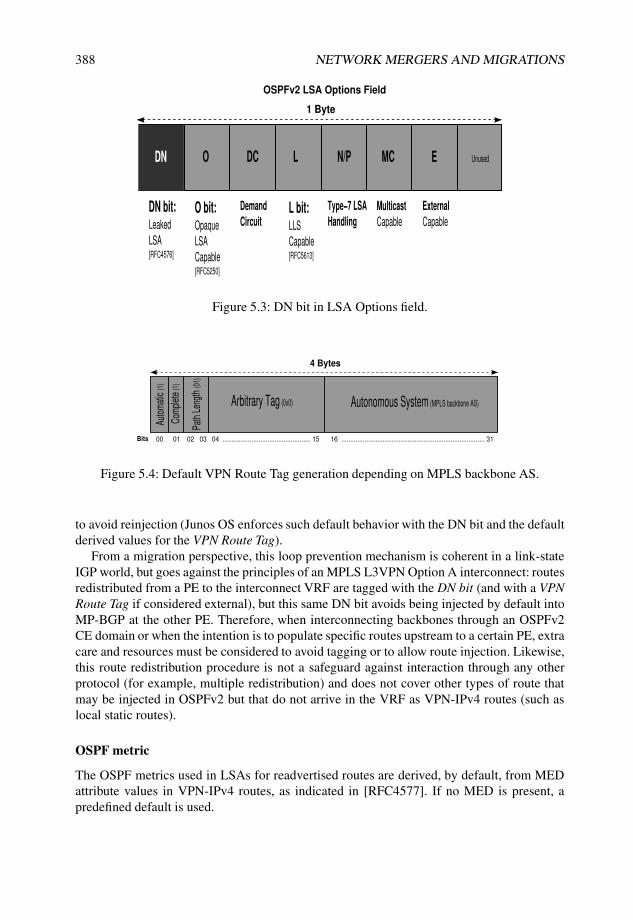
388 NETWORK MERGERS AND MIGRATIONS
1 Byte
DN bit:Leaked
LSA[RFC4576]
OSPFv2 LSA Options Field
DN O DC L N/P MC E Unused
O bit:Opaque
LSA
Capable[RFC5250]
External
Capable
Multicast
Capable
Type−7 LSA
Handling
Demand
CircuitL bit:LLS
Capable[RFC5613]
Figure 5.3: DN bit in LSA Options field.
4 Bytes
Auto
mat
ic(1
)
Com
plet
e (1
)
Path
Len
gth
(01)
Arbitrary Tag (0x0) Autonomous System (MPLS backbone AS)
00 01 02 03 04 ................................................. 15 16 ................................................................................ 31Bits
Figure 5.4: Default VPN Route Tag generation depending on MPLS backbone AS.
to avoid reinjection (Junos OS enforces such default behavior with the DN bit and the defaultderived values for the VPN Route Tag).
From a migration perspective, this loop prevention mechanism is coherent in a link-stateIGP world, but goes against the principles of an MPLS L3VPN Option A interconnect: routesredistributed from a PE to the interconnect VRF are tagged with the DN bit (and with a VPNRoute Tag if considered external), but this same DN bit avoids being injected by default intoMP-BGP at the other PE. Therefore, when interconnecting backbones through an OSPFv2CE domain or when the intention is to populate specific routes upstream to a certain PE, extracare and resources must be considered to avoid tagging or to allow route injection. Likewise,this route redistribution procedure is not a safeguard against interaction through any otherprotocol (for example, multiple redistribution) and does not cover other types of route thatmay be injected in OSPFv2 but that do not arrive in the VRF as VPN-IPv4 routes (such aslocal static routes).
OSPF metric
The OSPF metrics used in LSAs for readvertised routes are derived, by default, from MEDattribute values in VPN-IPv4 routes, as indicated in [RFC4577]. If no MED is present, apredefined default is used.

MPLS LAYER 3 VPN MIGRATIONS 389
From a migration perspective, it is important to ensure a smooth transition of the originalmetric to MED at the original advertisement site or adequate tuning of the BGP attribute.Very likely, this attribute may already be the tie-breaker in the remote VRF when selecting theactive path for the VPN-IPv4 route (independent of a common or distinct route distinguisher)prior to translation into an OSPFv2 LSA. Accurate MED setting is another step needed toguarantee that forwarding in the MPLS backbone takes place between the same CE sites asprior to a migration, in a plain OSPFv2 topology.
Figure 5.5 illustrates a basic decision flowchart to manipulate attributes for VPN-IPv4routes derived from the original Type 1, 2, or 3 LSAs at the root site (that is, from internalroutes in the OSPF domain).
OSPF LSA injection from VPN−IPv4 route (original Type 1,2,3 LSAs)
Need intra−area
route?
Yes No
’Sham Links’
Need inter−area
route?
matching’DomainIdentifiers’
No
No
Yes
Bleach ’DN bit’and ’VPN routetag’
Externalroute to be leaked
back toMPLS?
Yes
different’DomainIdentifiers’
Keep ’DN bit’ (default)and keep default ormodify ’VPN routetag’
Figure 5.5: Design alternatives to inject LSAs in a L3VPN CE domain originally derivedfrom OSPFv2 internal network routes.
5.2.4 EBGP as PE–CE protocol
Nowadays, external BGP is probably the most extended and commonly used interconnectoption between PE and the CE domains.
EBGP between PEs and CEs is simple, because it does not require specific redistributionpolicies among protocols, and because it is scalable as a transport protocol, offering the samevariety of TE options to steer traffic to and from each customer internal domain.
Despite not requiring any redistribution between protocols, a route transformation cer-tainly occurs when IPv4 unicast routes from the CE domain are transformed into VPN-IPv4routes with a RD and relevant extended communities are attached to the NLRI.
Such route transformation includes changes in BGP data structures and attributes that needto be considered from a migration perspective:

390 NETWORK MERGERS AND MIGRATIONS
• RDs define address uniqueness across the MPLS backbone or even, in the case in whichroutes are advertised beyond a single transport, the AS.
• AS_PATH is expanded with the transport AS when it is advertised from one VPN siteto another.
• If different VPN sites belong to the same AS (for instance, when splitting a legacynetwork into different VPN sites), the inherent BGP AS_PATH loop detectionmechanism discards updates from other sites if no manipulation is done, because thelocal AS is visible in the BGP AS_PATH at border CEs.
• Depending on the specific implementation, extended communities may be propagatedfrom PE to CE, even though the intention is to handle imports and exports out of everyVRF. This is particularly relevant in the case of inter-AS Option A, in which PEs maybe directly confronted with EBGP (see Section 3.2.4).
• Certain BGP attributes that may be present in IBGP no longer transition throughthe MPLS backbone because of the AS boundaries. This is especially relevant forLOCAL_PREFERENCE, a well-known attribute used to define TE policies insidean AS.
• IGP metrics towards the route next hop are a common path selection tie-breaker inmost modern router implementations. Because of the implicit next-hop rewrite onEBGP sessions, IGP metrics for these destinations change when transiting the MPLSbackbone.
When integrating a plain BGP network as part of a L3VPN, despite keeping the sameprotocol as the communication vehicle through the L3VPN backbone, such modifications inthe protocol setup need to be analyzed. In the end, newer EBGP sessions interact with theexisting setup to inject routes that originally were internal routes.
5.2.5 IBGP as PE–CE protocol
[draft-marques-ppvpn-ibgp-00] introduces an approach to transparently exchange BGProutes among CE sites.
As compared to using standard EBGP as the PE–CE protocol, in which the transportdomain AS is involved (or overwritten) in the AS_PATH and other attributes such asLOCAL_PREFERENCE, ORIGINATOR, and CLUSTER_LIST get lost when transiting ASboundaries, [draft-marques-ppvpn-ibgp-00] offers an approach to blindly encapsulate anddecapsulate the attributes in a new flexible attribute, ATTRSET, which acts as a container forthe originally inserted attributes with their values (except for the NEXT_HOP, MP_REACH,and MP_UNREACH attributes). This container acts as an attribute stack, into which theoriginal attributes are pushed by the advertising PE. They are popped at each VPN site whenperforming path selection in each VRF RIB, and at each site the PE’s real NEXT_HOP is setbefore sending the IPv4 native NLRI to the end CE.
Figure 5.6 shows the handling of this attribute when routes are propagating in a sampletopology.
This method provides numerous benefits when using BGP as the PE–CE protocol because,although the peer model with the PE router prevails, CEs can distribute their originally

MPLS LAYER 3 VPN MIGRATIONS 391
CE1
MPLS L3VPN
PE1PE2
CE2
IBGP PE−CE
IBGP PE−CE
Local−preference
MED
AS Path: I
Next−Hop:CE1
Clusterd ID
Originator ID
etc.
Local−preference
MED
AS Path: I
Next−Hop:PE1
etc.
ATTRSET
Local−preference
MED
AS Path: I
Clusterd ID
Originator ID
etc.
Local−preference
MED
AS Path: I
Next−Hop:PE2
Clusterd ID
Originator ID
etc.
PE1 pushing
original attttributes
into ATTRSET stack
at VPN−IPv4 NLRI
attributes except
from original
Next−Hop
PE2 popping
original attttributes
from ATTRSET stack
as IPv4 NLRI
attributes over
IBGP PE−CE doing
Next−Hop−self
Original Next−Hop
is not copied into ATTRSET
MP−IBGP PE1−PE2
VPN−IPv4 AFI/SAFI
Figure 5.6: BGP attribute handling per draft-marques-ppvpn-ibgp-00.
intended TE attributes in a transparent fashion, opaque to the transport in the MPLSbackbone. Considering a legacy plain network whose main route advertisement vehicleis IBGP, this feature is a powerful tool to expand regions into VRF sites easily withoutmodifying the route distribution policies. Indirectly, PEs act as route reflection points forall routes arriving by means of VPN-IPv4 NLRIs towards each CE attachment world andtherefore multiplex routing information from all VPN remote sites.
From a migration perspective, note that this attribute handling is completely orthogonalto whatever IGP or BGP hierarchies are run at each site. It merely provides transparent routeredistribution, end to end, through the VPN backbone.
5.2.6 Inter-AS options
Interconnecting third-party networks using L3VPNs is addressed by simulating those third-party networks as CE devices. To minimize the impact of such a migration, the PE–CEprotocol is adapted to the third-party network. However, in some cases the customer isanother service provider, and the interconnection arrangement is a way to partner foradditional reachability or redundancy.
Inter-AS connectivity established using any of the pre-existing PE–CE protocols followsthe so-called Option A interconnect as defined in Section 10 of [RFC4364]. The samespecification provides two additional options to improve scalability, based on the forwardingplane traffic on the interconnect: Option B for single-stacked MPLS traffic, and Option C

392 NETWORK MERGERS AND MIGRATIONS
for double-stacked MPLS traffic. These are shown in Figure 5.7. A short comparison of thevarious options is shown in Table 5.1.
L1a
L1a
L1a
L1a
L1c
LV1
LV1
LV1
LV1
LV1
LV1
LV1
LV1
LV1
LV1 LV2
per VRF IP
IPIP
L1d
L1d
L1d
L1d
L1e
L1e
L1e
L1e
L1b
L1b
L1b
L1b
R1
VPN
VPN
VPN
VPNOption C
BGP
Option B
Option A+B
Option A
Transport
Transport
Transport
Transport
R2 R3 R4 R5 R6
Figure 5.7: Inter-AS L3VPN interconnection alternatives.
Table 5.1 Comparison of L3VPN inter-AS interconnects
Consideration IP inet-vpn labeled-inet(Option A) (Option B) (Option C)
IP features yes no noMPLS no 1 label 2 labelsInterconnect multiple single singleScalability per IP prefix per VPN per PE
Option A: IP packet as the PE–CE transport
In [RFC4364] Section 10, Option A, the interconnecting ASBR router behaves like a regularPE device. This router has complete control over redistribution and policy, and prefixaggregation within a VRF is readily available. All regular IP features available on a regularPE device (such as packet filtering, per-VRF statistics, and logging) are also available at thisborder point.
Customer-specific class-of-service requirements can be applied to each subinterfaceat the interconnection. Each customer can get differentiated IP precedence marking and

MPLS LAYER 3 VPN MIGRATIONS 393
traffic shaping. For instance, partnering with international VPNs can have traffic shapingenabled on the interconnect, limiting the amount of total off-net traffic.
Any VPNs that require interconnection must be present, which poses a scalability concern.Besides, a different PE–CE interface for each VRF can be cumbersome from a provisioningperspective, especially when the Layer 2 media is not directly connected. A typical exampleis the use of different logical circuits represented by combinations of VPIs and VCIs in anATM network.
Option B: Single stacked MPLS-labeled packet as the PE–CE transport
In [RFC4364] Section 10, Option B, a first level of scalability is added by exchanging VPN-labeled traffic. Similarly to a provider with two PEs directly connected to each other, the twoASBRs exchange inet-vpn prefixes but have no transport label. Being two different providers,the BGP interconnection is of an external nature, and additional provisions for transiting ofVPN traffic have to be taken into account. A similar setup can be attained by using RouteReflection for internal connections.
In an Option A, the semantics for the RT are lost because the exchange does not takeplace over MP-BGP. The interconnecting subinterface provides the binding between routesand target VRF. Conversely, there is a true VPN blending in Option B, requiring agreementon the RT tagging policy to be used for interconnected VPNs. Two approaches are commonpractice:
• Defining a new RT for shared VPNs. This requires tagging import and export policiesfor all PEs where this VPN has a corresponding CE attachment through a VRF,irrespective of the carrier domain. This makes sense for newly provisioned VPNswhere the multidomain connectivity requirements are known. Typically, the L3VPNNLRI ends up with more than one RT community; the intradomain RT community isnot changed, but rather, an additional community representing the intercarrier policy isspecified.
• Provide translation at the VPN border. RT community translations are set up forselected VPNs at the ASBR as part of the inter-AS peering agreement. Most commondesigns centralize VPN reachability information in a couple of redundant L3VPNRoute Reflectors, which become an interesting place to conduct the RT communitymapping. Section 5.6.5 in the case study uses this strategy.
Option C: Dual-stacked MPLS label as the PE–CE transport
In the approach dubbed Option C, the VPN-labeled traffic is not directly connected andrequires some means of end-to-end transport between the PEs. For an extensive discussionabout the approach to build an MPLS transport tunnel between PEs and ASs, see the casestudy in Chapter 4.
The Option C alternative is used when extending all VPNs in a network or when movingPEs between networks, to minimize the impact. Each domain has labeled paths to the PEsin the other domain, so a PE homes VPNs for any of the domains in a seamless way. Thisis a good choice when integrating networks or moving PE routers between networks, but agood level of coordination must exist between the two groups, including the NOCs, perimetersecurity, management, accounting, and planning.

394 NETWORK MERGERS AND MIGRATIONS
Two alternatives are defined to interconnect using Option C:
• Labeled-BGP. This alternative leverages the flexible policy knobs of BGP to constrainadvertisement or further protect each peer from instabilities caused by the other peer.
• LDP plus an IGP of choice. Because LDP relies on a routing protocol for its labeladvertisement decision process, it is also required to combine FEC advertisement withan additional routing protocol.
Option A+B: Single-stacked MPLS with IP functionality
Various proposals (now expired) have been made requesting standardization for a scenariothat is a combination of Options A and B, such as [draft-kulmala-l3vpn-interas-option-d].The described proposal requires behavior changes on the ASBR device, but does nototherwise modify the interaction between systems (no new messages are defined, and existingbehaviors are maintained).
In this modified approach, the end-to-end MPLS path between two PEs is broken at theASBR border, triggering a lookup in the underlying application layer. The goal is to retainthe benefits of an Option A interconnection from the application visibility perspective whileleveraging the scalability enhancements provided by the Option B MPLS interconnection.
Application Note: Scaling L3VPNs with hierarchical PE
A variation of the inter-AS approach proposed as Option A+B discussed in Section 5.2.6can be applied within the same AS, to obtain the benefits of an MPLS interconnect forscalability, while leveraging IP functionality for aggregation purposes.
PE
Nantes10.10.1.1
10.10.1.9
Virtualized CE
Inverness
Frame Relay
access
DLC
I 101
DLC
I 102
DLC
I 100
To cover more departments with differentiated
routing at customer premises, regular approach
is to virtualize the CE and to extend the number
of subinterfaces interconnecting PE and CE.
per subinterface
PE−CE routing
IBGP full meshMPLS L3VPN
Figure 5.8: Adding low-capacity PE through aggregation.

MPLS LAYER 3 VPN MIGRATIONS 395
Looking at the MPLS L3VPN network in Figure 5.8, the CE router Inverness, withvirtualization capabilities, is a low-cost strategy because the customer requires separateconnectivity for each department. The initial approach is to use virtual-router instances tosegregate each department’s routing information and to use a separate logical connection tothe PE router Nantes. Because the CE router cannot handle all VPN information, the edgePE Nantes performs prefix aggregation, advertising only selected route blocks.
A roadblock that might prevent general deployment of this solution is the existence ofa Layer 2 infrastructure (Frame Relay, ATM, or Metro Ethernet) in the interconnection.Adding a new VRF on the PE and a new virtual router on the CE also requires provisioningof a new subinterface, with the usual lead times and operational coordination.
The approach of introducing the Customer Premises device in the MPLS L3VPN (withfull visibility) is very attractive from the provisioning point of view, because an MPLS pipesubstitutes for the multiple set of PE–CE connections. However, this may not be desirabledepending on the capabilities of the low-end CE device. As an added constraint in thisexample, the router Inverness is a small-capacity device, which can serve only a minimalset of VRFs and does not cope well maintaining an IGP of hundreds of PE devices.
The careful reader may have noticed that the first approach maps nicely to an OptionA interconnect, because it is a regular PE–CE interconnection. Hiding full visibility ofthe whole MPLS L3VPN network while benefiting from the Option B advantages can beachieved by treating both router Nantes and router Inverness as ASBRs of an Option Binterconnect. If router Nantes advertises itself as the next hop for all announcements, routerInverness does not require full topological information.
HPE
Nantes10.10.1.1
10.10.1.9
LPE
Inverness
PE Basel
10.10.1.3
so−0/1/0.0
fe−0/3
/1.0
fe−0/3
/1.0
172.16.2
00.0/2
4
172.11.1.96/30
10.10.1.10
172.16.1.64/30
so−0/0/1.0
so−1/0/1.0
so−0/2/0.0
BGP full mesh
MPLS L3VPN
OSPF
area 0.0.0.0
P Torino
IBGP
Cluster
1.1.1.1
policy−statement Aggregate−routes−only {
term aggregates {
from {
community Aggregate−route;
}
then next−hop self;
}
term block−remainder {
then reject;
}
}
The HPE has instantiated copies of the VRFs; only specifically
tagged routes (corresponding to aggregates) are to be advertised
downstream. This requires forwarding traffic to perform an IP
lookup in search of more specific prefixes.
Prefixes from the LPE are advertised into the cloud with no further modification.
MP−IBGP
LDP
MP−IBGP
LDP
IBGP export at HPE towards the LPE
Customer VRF has multiple prefixes that can not be handled
by LPE. Define some aggregate blocks that will be the ones
to forward down to LPEs, and keep more specifics within
the regular PE domain. BGP Community tagging allows for
selective advertisement at the HPE.
Figure 5.9: Hierarchical PE concept with route reflection.
Although the regular Option B is meant to interconnect ASs through EBGP, thisApplication Note provides a feasible alternative within the AS by means of route reflection,as shown in Figure 5.9. Router Nantes becomes a High-end PE (HPE) in the hierarchy, with

396 NETWORK MERGERS AND MIGRATIONS
router Inverness acting as the Low-end PE (LPE). Both HPE and LPE require inter-ASASBR capabilities. In addition, the HPE should be able to trigger an IP lookup for trafficthat follows the aggregate advertisements. In Junos OS, by default, instantiating a VRF andallocating a Table Label (using vrf-table-label or Virtual Tunnel interfaces) is enough toenable this functionality.
Note A table label VRF advertises the same table label over inet-vpn for all routes,whether the routes originated locally within the VRF or through readvertisement ofreceived inet-vpn routes belonging to the VRF.
A combination of route reflection and BGP export policy controls what has to beadvertised downstream to the LPE. Using BGP community tagging, the aggregates donot need to be sourced locally, giving a single point of control at the ingress PE thatapplies to all HPEs. If desired, use of route-filter in policy paired with proper extendedRT communities can constrain advertisement of specific prefixes.
As the configuration in Listing 5.1 shows, a single inet-vpn session is establishedbetween WAN interface addresses to the HPE. Because of the inherent multihop natureof IBGP, it is necessary to leak these interface addresses into the inet.3 table properly toresolve received prefixes. Listing 4.21 in Chapter 4 on Page 338 provides more detail.
Listing 5.1: LPE Inverness setup
1 user@Inverness> show configuration protocols bgp2 group IBGP {3 type internal;4 local-address 10.10.1.66; # Local WAN address on LPE5 family inet-vpn {6 unicast;7 }8 neighbor 10.10.1.65; # WAN address at LPE9 }
10 user@Inverness> show configuration routing-options rib-groups11 int-to-inet3 {12 import-rib [ inet.0 inet.3 ];13 import-policy interface-to-inet3; # Leak WAN interface to inet.314 }15 user@Inverness> show configuration routing-options interface-routes16 rib-group inet int-to-inet3;17
18 user@Inverness> show configuration policy-options policy-statement19 interface-to-inet320 term LPE-nh {21 from interface so-0/0/1.0;22 then accept;23 }24 term no-more-inet3 {25 to rib inet.3;26 then reject;27 }
At the HPE router Nantes, configuration requires use of policy language to constrainadvertisements to the LPE Inverness. A sample policy is shown in Listing 5.2.
Listing 5.2: Use of policy at HPE to constrain advertisement to LPE
1 user@Nantes> show configuration protocols bgp2 group IBGP {3 type internal;4 local-address 10.10.1.1;5 family inet-vpn {

MPLS LAYER 3 VPN MIGRATIONS 397
6 unicast;7 }8 export nhs;9 inactive: neighbor 10.10.1.3;
10 neighbor 10.10.1.10;11 }12 group IBGP-LPEs {13 type internal;14 local-address 10.10.1.65; # WAN address of Nantes towards LPE Inverness15 family inet-vpn {16 unicast;17 }18 export [ nhs Aggregate-routes-only ];19 cluster 10.10.1.1; # Route reflection20 neighbor 10.10.1.66;21 }22 user@Nantes> show configuration policy-options policy-statement23 Aggregate-routes-only24 term aggregates {25 from community Aggregate-route;26 then next policy;27 }28 term block-others { # Do not readvertise prefixes by default29 then reject;30 }
The next-hop self policy on Line 18 is required to ensure that all BGP reachabilityinformation on router Inverness can be resolved properly through the HPE router Nantes.Failure to add this policy would require router Inverness to contain a labeled path towardsrelevant PE loopback addresses in inet.3.
The cluster knob that enables reflection (Line 19) is not strictly required in the HPEto LPE advertisement direction if aggregates are configured locally on router Nantes insteadof on the ingress PEs. For advertisements in the reverse direction, updates coming from theLPE router Inverness may also get only as far as the HPE, with appropriate aggregationbeing performed at the HPE to readvertise into the backbone. However, because scalabilityinto the backbone should not be a concern, reflecting the routes provides direct visibility toLPE reachability information.
Notice that the policy match in Line 25 specifies routes with a community. A route filtercan be applied instead.
Junos Tip: Matching prefixes for inet-vpn routes
As part of Junos OS policy-based filtering for inet-vpn routes, a route-filter matchcondition can be added to restrict further the routes to be advertised. The route-filtermatch ignores the RD part of the NLRI. Combining the route-filter with an extendedcommunity match is recommended to scope the match to the intended VPN. Section 5.6.5in the case study on Page 484 uses this feature to filter more-specific routes for anaggregate route.
5.2.7 Carrier Supporting Carrier (CsC)As a natural evolution of an IP-based L3 VPN service, [RFC4364] also allows for MPLStraffic to be contained in the VPN. The applicability of this scenario is relevant when a carrierhas no local homing of the customer’s VPN routes within its AS, thus optimizing resource

398 NETWORK MERGERS AND MIGRATIONS
consumption. In this scenario, the customer buys an MPLS connecting service, exchanging IPinformation used to build the transport tunnels across the provider VPN. A separate instanceis allocated for this MPLS VPN, with properties similar to IP MPLS L3VPNs.
As with Option C described in Section 5.2.6, both L-BGP and a combination of LDP plusthe IGP of choice are defined to convey the label information for these FECs.
Relying on third-party backbone infrastructure to build an MPLS L3VPN may be anattractive proposition. From a migration perspective, migrating may be as simple as carefullycontrolling the FEC advertisements within and outside of the domain.
In an enterprise scenario, a CsC setup may be interesting when part of the enterprisewants to build and administer VPNs independently, while leveraging the L3VPN coreinfrastructure. As an example, a manufacturing plant connected to the research laboratoriessharing several VPNs can be hidden behind a CsC VPN supported by the IT depart-ment.
Note that the major goal of CsC is to separate the two infrastructures. Thus, this option isfeasible when the inner and outer VPN layers do not require direct interconnection.
5.3 Generic Strategies for L3VPN Migrations
With all the possible expansion and interconnect models for L3VPNs, there are multipletechnical alternatives for migrations. By correctly aligning and combining these alternatives,several strategies for migration can be planned and implemented.
5.3.1 Layer VPN Route Target mapping
A RT ultimately determines L3VPN membership and can be arbitrarily tagged to each VPN-IPv4 route. More than a single RT can be tagged at VRF export, and any value can be expectedfor VRF import.
This multiple setting and matching mechanism is a powerful vehicle for a soft transitionof L3VPNs. Routes can arbitrarily include multiple RTs at a transition stage, making themeligible to be imported into more than a single VRF. Depending on how reverse flows are setup, such multiple appearance in more than one VRF ensures that a destination can be presentin multiple VRF tables as long as needed.
This behavior of matching and setting multiple arbitrary RTs allows granularity on a per-route basis and is commonly deployed as a permanent design in extranets or other hub-and-spoke topologies.
5.3.2 Layer 3 VPN Route Distinguiser mapping
RDs are embedded into VPN-IPv4 prefixes. These data structures cannot be applied multipletimes to the same IPv4 prefix inside the same VRF, because the combination of a RD and anIPv4 prefix create a unique VPN-IPv4 route.
Deploying common or distinct RDs across VPN sites has been a tradeoff made in severalMPLS backbones. Defining granular RD (usually on a per-VRF, per-PE basis) grants anotherdistinguishing factor to the route and therefore multiplies the paths, allowing additionalresilience towards the destination in multihomed CE domains. On the other hand, this implicitroute multiplication leads to additional memory consumption and has a clear scaling impact.

MPLS LAYER 3 VPN MIGRATIONS 399
By using several RDs for the same root IPv4 prefix, more paths are available for selectionand installation in the end device’s VRF, allowing for quicker convergence when primarypaths disappear.
5.3.3 Parallel L3VPNs
Another approach distinguishes different L3VPNs as planes between CE domains. Thetransition does not take place inside the MPLS backbone by keeping the same VRF, butrather, between PEs and the CE domain by including uplinks in separate VRFs.
CEs are therefore multihomed to more than a single VRF. Despite injecting the sameIPv4 prefix into the PE, different RDs allow duplicate destinations within the core and allowmultiple RTs in each VRF, thus virtually creating parallel topologies, which allows for aseamless migration from one VPN to another.
5.3.4 Interconnecting L3VPNs
Section 5.2.6 describes inter-AS connection options with L3VPNs. These methodologies areused to expand L3VPNs beyond a single carrier with the intention of integrating services andapplications.
A migration strategy may start with a simple inter-AS Option A, and transition or combinedifferent options to achieve the best of all worlds in common ASBRs. For instance, a simpleOption A Interconnect providing IP layer operations such as filtering or accounting can beprogressively expanded with an Option B for consolidated route advertisement while keepinglocal Option A interconnects for some VRFs that require IP header inspection.
5.4 Junos Implementation of L3VPNs
If multiple sites are connected to the same PE and they have disjoint VPNs, Junos OSimplements those sites in separate routing and forwarding tables. If those local VRF sitesshare any VPNs, Junos OS still creates separate routing and forwarding tables for each VRF,and the routes from each site are shared by the mechanisms described in Section 1.2.3 so thattraffic can be forwarded among local VRFs with a common RT or with artificially sharedroutes using rib-groups.
BGP next-hop reachability checks are implemented per default in Junos OS for VPN-IPv4NLRIs. These checks not only require the next hops to be present and reachable in inet.0only, but also when indirect resolution for these prefixes is required, these next hops must beidentified as FECs with a valid, existing label binding in inet.3. VPN-IPv4 prefixes whosenext hops are not active in inet.3 are not installed and are immediately discarded, unlesskeep all is configured, in which case they remain hidden in Junos OS terminology.
The VRF paradigm introduces several concepts in Junos OS that at the time of this writingare trivial but are the cornerstone of L3VPN implementations:
• The Routing Instance concept was leveraged: the capability exists to define routingoptions and protocols inside a routing instance, in a manner similar to the default,together with a proper interface association to a specific instance.

400 NETWORK MERGERS AND MIGRATIONS
• Dynamic RIBs are created for each VRF instance: a separate set of routing tables isflexibly assigned to each VRF.
• Enhancement of RIB list structures to properly associate protocol-imported prefixes toRIBs for addition or deletion at each one.
• BGP mechanisms such as Capability advertisement and Refresh were first introducedwith the VPN-IPv4 family to allow these routes to be able to negotiate their supportwith a peer, and to let the BGP peer know of the requirement to refresh and send agiven set of routes, thus avoiding the need to keep all VPN-IPv4 routes (not all neededat a given time if a local matching VRF does not exist).
• BGP needed to coordinate MPLS label assignments and relinquishments for eachVPN-IPv4 route to avoid overlapping and ensure proper forwarding.
• On the forwarding plane, the Packet Forwarding Engines (PFEs) needed to be readyfor a minimum of a double label push or pop (excluding other mechanisms such as fastreroute variations or LDP tunneling over RSVP that may require additional labels inthe stack).
• At the kernel and routing socket level, the prior interface-VRF association has to beimplemented with multiple tables per address family. Ultimately, this means multipleforwarding tables per address family as dictated by the interfaces in each VRF touniquely identify each route change.
• The complex forwarding structures among VRFs or between a VRF and the defaultrouting instance described in Section 1.1 require specific next hops that can be madevisible across VRFs or can directly point to another RIB and be VRF-specific whenhardware lookups occur.
• The traditional single route lookup paradigm in Junos OS needed to be improved toallow both an MPLS VPN label lookup to the proper VRF and an IP lookup inside aVRF simultaneously on PEs for incoming traffic.
This last bullet has been discussed for many years: Junos OS-based platforms haveimproved mechanisms to ensure hardware-based single lookups per flow. The need to accom-modate a double lookup arose later, as soon as more than a single CE interface was presenton a VRF or when particular capabilities requiring IP lookups were deemed necessary.
5.4.1 MPLS label allocation for L3VPNs
By default, when advertising VRF information into the core, Junos OS allocates one VPNlabel to every next hop that requires forwarding within a VRF. If the prefix is not to beadvertised, this allocation does not take place.
Traffic arriving over the core interface that uses this VPN label is mapped to the final nexthop, and traffic is forwarded out of the VRF with no further processing.
In a nutshell, hardware-based line-rate forwarding structures in Junos OS-based platformsare based on certain key value extraction from incoming packets to perform a single lookupto determine the destination for the traffic and possibly apply other actions (such as sampling

MPLS LAYER 3 VPN MIGRATIONS 401
and port-mirroring). This single-lookup premise poses a challenge for incoming backbonetraffic at PEs in certain scenarios:
• Outgoing firewall filtering on the PE–CE interface for policing, implementing securityrules, multifield reclassification, sampling, and other actions.
• When an additional IP lookup is needed inside the VRF to reach another VRFtermination over a medium shared by PE–CE for additional resolution.
Juniper Networks engineers developed a solution to allow double lookup: table labels.This concept is based on the allocation of a common MPLS label for all prefixes within eachVRF.
Allocation of table labels is possible using either Label-Switched Interfaces (LSIs) orVirtual Tunnel (vt) interfaces. Once a VRF is configured for table-label functionality, allprefixes are advertised with this label by default. It is possible to change the allocation andrevert to the default for each next-hop allocation.
L3 VPN table label with vrf-table-label
The virtual LSI’s infrastructure enables a packet to be received directly tagged with a specificlabel as if it arrives on the LSIs. Indirectly, the VRF lookup has been performed and theASICs are now ready to perform the needed IP lookup for IPv4 prefixes identified after VPNlabel decapsulation is performed by the LSIs. This LSI-VRF table binding is uniquely foreach MPLS VPN label, which is mapped on all regular core-facing interfaces to the LSI anddirectly extracts IPv4 traffic inside the VRF context.
Routes inside the VRF configured with the vrf-table-label knob are advertisedwith the same special label allocated for that VRF. As arriving packets for the VRF are passedthrough the LSI structure and MPLS labels are detached, an IP lookup is performed as if theywere arriving on the VRF through the LSI, permitting the configuration of arbitrary PE–CE egress filtering to implement the same policies and rules that could be achieved for anylocal traffic between two PE–CE interfaces inside a VRF. Listing 5.3 shows related resourcesvisible through the Junos OS CLI for LSI interfaces associated with each VRF (Line 16) andhow a VPN table label is allocated in the mpls.0 routing table with a fake route (Line 25): itissues a proper lookup for traffic in the table referred as Next-Table.
Listing 5.3: Simple VRF-table-label implementation at router Livorno for route lookup
1 user@Livorno> show configuration routing-instances2 nmm {3 instance-type vrf;4 interface fe-0/3/0.0;5 route-distinguisher 65000:65000;6 vrf-target target:65000:65000;7 vrf-table-label; # Table label allocation for this VRF8 }9
10 user@Livorno> show interfaces routing-instance nmm terse11 Interface Admin Link Proto Local Remote12 fe-0/3/0.0 up up inet 172.16.100.8/2413 172.16.100.108/2414 iso15 inet6 fe80::214:f6ff:fe85:405d/6416 lsi.0 up up inet # LSI interface associated with VRF nmm table-label17 iso

402 NETWORK MERGERS AND MIGRATIONS
18 inet619
20 user@Livorno> show route table mpls extensive21
22 mpls.0: 1 destinations, 1 routes (1 active, 0 holddown, 0 hidden)23 16 (1 entry, 0 announced)24 *VPN Preference: 025 Next table: nmm.inet.0 # Action for VRF nmm table-label received lookup26 Label operation: Pop27 Next-hop reference count: 128 State: <Active NotInstall Int Ext>29 Age: 38:4830 Task: RT31 AS path: I
This implementation concept leads to two different effects:
• Because a VRF lookup is indirectly performed with the LSI association, full IP lookupcapabilities are available inside the VRF.
• Assigning the same VRF table label for all IPv4 prefixes from a VRF reducesconsumption of MPLS labels.
Junos Tip: VRF EXP classification with vrf-table-label
When the vrf-table-label feature is activated, the default MPLS EXP classifier isapplied to the routing instance. Indirectly, the complete VPN table label is represented bythe LSI, so in the ultimate hop to the PE, the inner label is directly matched with the LSI,and EXP bits are checked for an initial classification on the LSI.
If the Juniper Networks router PIC containing the PE–P interface is installed on any typeof Enhanced FPC, this default indirect multifield classification on the LSI can be overriddenwith an arbitrary customer EXP classifier, the one intended for VPN label EXP inspection(usually the same Multifield classification from the core). Listing 5.4 depicts the changesneeded on top of Listing 5.3 for a VRF-specific EXP classification and how to inspect theresults. Line 14 indicates that the EXP-based Multifield classification is actually applied onthe allocated LSI to that VRF.
Listing 5.4: EXP classifier with VRF-table-label implementation at router Livorno
1 user@Livorno> show configuration class-of-service classifiers exp NMM2 import default;3 forwarding-class assured-forwarding {4 loss-priority low code-points [ 000 001 010 011 100 101 ];5 }6
7 user@Livorno> show configuration class-of-service routing-instances nmm8 classifiers {9 exp NMM;
10 }11 user@Livorno> show class-of-service routing-instance12 Routing instance: nmm13
14 Logical interface: lsi.0, Index: 69 # LSI allocated to VRF nmm with EXP classification15 Object Name Type Index16 Classifier NMM exp 58329

MPLS LAYER 3 VPN MIGRATIONS 403
This EXP-based classification can also be enabled for other VPN types, such as VPLSLSIs, on MX-series platforms. Note that this feature is currently not supported wheneverVRFs are defined inside logical systems.
Assigning a common VRF table label should be considered a best practice from animplementation perspective: IPv4 prefixes should already be unique or duplicated inside aVRF, and the IPv4 prefix part of a VPN-IPv4 route should already disambiguate destinationsonce the VRF is reached. In other words, having a common VRF table label does notaffect forwarding to destinations inside the VRF and saves numerous resources in terms ofMPLS labels and next-hop allocations. This can be helpful from a migration perspective, butalso the opposite intention could be an ultimate goal when implementing L3VPNs: avoidan IP lookup in a PE–CE termination and blindly forward traffic to the CE. Scenariossuch as a hub-and-spoke extranet or an inter-AS Option A interconnect in which trafficneeds to be sent to a CE inside a particular VRF site without looking into the real IPdestination address inside can be easily implemented by avoiding the vrf-table-labelconcept.
L3VPN table label with virtual tunnel interfaces
Another internal VRF lookup alternative is available in devices that have a Tunnel PIC: thedefinition of a virtual tunnel interface associated with each VRF. The fundamentals of thisstructure are based on traffic first transiting through the virtual loopback tunnel to detach theMPLS VPN label and then issuing a proper IP lookup after the loop.
These virtual loopback tunnel logical interfaces are defined following the Tunnel PIClocation, need to include family inet and family mpls, and need to be includedin the VRF for each logical unit for proper lookup. Listing 5.5 shows the configurationsnippet needed and the effects in terms of VRF-related interfaces. Line 4 highlights the needto include the full logical vt- extension inside the VRF. Note that this feature is mutuallyexclusive with vrf-table-label, and an LSI is no longer allocated for the VRF.
Listing 5.5: Simple virtual loopback tunnel implementation at router Livorno for route lookup
1 user@Livorno> show configuration routing-instances nmm2 instance-type vrf;3 interface fe-0/3/0.0;4 interface vt-1/2/0.0; # VT logical interface matching Tunnel PIC location5 route-distinguisher 65000:65000;6 vrf-target target:65000:65000;7
8 user@Livorno> show configuration interfaces vt-1/2/0.09 family inet;
10 family mpls;11
12 user@Livorno> show interfaces routing-instance nmm terse13 Interface Admin Link Proto Local Remote14 fe-0/3/0.0 up up inet 172.16.100.8/2415 172.16.100.108/2416 iso17 inet6 fe80::214:f6ff:fe85:405d/6418 vt-1/2/0.0 up up inet # VT interface, no longer LSI19
20 user@Livorno> show interfaces vt-1/2/0.021 Logical interface vt-1/2/0.0 (Index 86) (SNMP ifIndex 245)22 Flags: Point-To-Point 0x4000 Encapsulation: Virtual-loopback-tunnel # Reserved vt tunnel
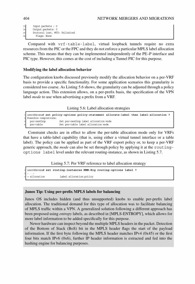
404 NETWORK MERGERS AND MIGRATIONS
23 Input packets : 024 Output packets: 025 Protocol inet, MTU: Unlimited26 Flags: None
Compared with vrf-table-label, virtual loopback tunnels require no extraresources from the PIC or the FPC and they do not enforce a particular MPLS label allocationscheme. This means that they can be implemented independently of the PE–P interface andPIC type. However, this comes at the cost of including a Tunnel PIC for this purpose.
Modifying the label allocation behavior
The configuration knobs discussed previously modify the allocation behavior on a per-VRFbasis to provide a specific functionality. For some application scenarios this granularity isconsidered too coarse. As Listing 5.6 shows, the granularity can be adjusted through a policylanguage action. This extension allows, on a per-prefix basis, the specification of the VPNlabel mode to use when advertising a prefix from a VRF.
Listing 5.6: Label allocation strategies
1 user@Havana# set policy-options policy-statement allocate-label then label-allocation ?2 Possible completions:3 per-nexthop Set per-nexthop label allocation mode4 per-table Set per-table label allocation mode
Constraint checks are in effect to allow the per-table allocation mode only for VRFsthat have a table-label capability (that is, using either a virtual tunnel interface or a tablelabel). The policy can be applied as part of the VRF export policy or, to keep a per-VRFgeneric approach, the mode can also be set through policy by applying it at the routing-options label level under the relevant routing-instance, as shown in Listing 5.7.
Listing 5.7: Per VRF reference to label allocation strategy
1 user@Havana# set routing-instances NMM-Big routing-options label ?2 <...>3 + allocation Label allocation policy
Junos Tip: Using per-prefix MPLS labels for balancing
Junos OS includes hidden (and thus unsupported) knobs to enable per-prefix labelallocation. The traditional demand for this type of allocation was to facilitate balancingof MPLS traffic within a VPN. A generalized solution following a different approach hasbeen proposed using entropy labels, as described in [MPLS-ENTROPY], which allows formore label information to be added specifically for this purpose.
Newer hardware can inspect beyond the multiple MPLS headers in the packet. Detectionof the Bottom of Stack (BoS) bit in the MPLS header flags the start of the payloadinformation. If the first byte following the MPLS header matches IPv4 (0x45) or the firstfour bits match IPv6 (0x6), further IP header information is extracted and fed into thehashing engine for balancing purposes.

MPLS LAYER 3 VPN MIGRATIONS 405
Application Note: Selective label allocation for hub-and-spoke VPN
The per-next-hop default label allocation scheme in Junos OS is perfectly suited for hub-and-spoke VPNs with a single VRF, in which spoke traffic is directed to the hub, thusbypassing a best-match IP prefix lookup. When the hub PE has also locally attachedCEs that are on a broadcast media, as shown in Figure 5.10, it is necessary to activateIP functionality to allow ARP resolution to occur.
The conflict of needing MPLS forwarding for the hub site and at the same timeleveraging IP functionality for the CEs on the same VRF can be resolved either by movingthe hub site onto a separate VRF with table-label functionality or by leveraging the per-next-hop allocation capability feature.
Ethernet shared media
Hub locationCE CE CE
vrf−exporthub routestarget:64502:1
vrf−importspoke routestarget:64502:2
PE
MPLS L3VPN
RIB
Figure 5.10: Hub-and-spoke requiring ARP for the local CE.
Listing 5.8 shows a sample configuration for a Hub VRF with table-label functionalityenabled (Line 6) that is overridden globally to per-next-hop mode (Line 9). Besides theusual vrf-export policy that tags the hub prefixes, an additional vrf-export policy reactivatesthe table-label capability for direct routes (Line 5), allowing for ARP resolution whilemaintaining per-next-hop functionality for the remaining prefixes towards the hub site.
Listing 5.8: Hub-and-spoke with per-table policy for direct routes
1 user@Havana# show routing-instances NMM-Hub2 instance-type vrf;3 interface so-1/0/0.100;4 vrf-target import target:64502:2; # Import Spoke community5 vrf-export [ table-for-direct tag-hub ]6 vrf-table-label; # Use of table label by default7 routing-options {8 label {9 allocation default-nexthop; # Default to next-hop allocation

406 NETWORK MERGERS AND MIGRATIONS
10 }11 }12 user@Havana# show policy-options policy-statement table-for-direct13 term direct {14 from protocol direct;15 then label-allocation per-table;16 }17
18 user@Havana# show policy-options policy-statement default-nexthop19 term default {20 then {21 label-allocation per-nexthop;22 accept;23 }24 }25 user@Havana# show policy-options policy-statement tag-hub26 then {27 community add Hub;28 accept;29 }30 user@Havana# show policy-options community Hub31 members target:64502:1;
Substituting transit labels in MPLS routes
As discussed in Section 3.2.10, the BGP protocol decouples the physical layer from thecontrol plane by introducing a level of indirection through the protocol next hop. Whenthe reachability information contains MPLS labels, this level of indirection has someimplications worth exploring for cases when an intermediate device performs a change inthe next hop.
When the BGP protocol next hop is modified for an MPLS route, the context of theinformation changes as well. MPLS label values are meaningful only to the originator ofthe label. Changing the originator of a BGP update for an MPLS route by changing the nexthop to self requires the new advertisement to have an MPLS label that is understood by theoriginating router. Note that the previous label might already be allocated to another service,or it might be outside the label pool capabilities of this router. Hence, the readvertising routerhas to allocate a new label and bind this label to the old MPLS information in the MPLSforwarding table.
In Junos OS, this new VPN label advertised is normally taken from the global pool and isbound to the incoming label with an MPLS label swap operation. Traffic coming in with thislabel is MPLS-switched and the advertised label is changed with the original label.
If the label to be advertised is the table label allocated to one of the VRFs, traffic isreceived on the IP VRF and an IP lookup takes place. This effectively breaks the end-to-endMPLS path and enables IP transit functionality.
In Junos OS, it is possible to control the allocation of VPN labels for transit MPLS routes,as shown in Listing 5.9. The associated policy should accept or reject that the advertisedlabel is a table label instead of a regular label for a particular prefix.
Listing 5.9: Per-VRF reference to transit label substitution strategy
1 user@Havana# set routing-instances NMM-Big routing-options label ?2 <...>3 + substitution Label substitution policy

MPLS LAYER 3 VPN MIGRATIONS 407
Junos Tip: Choosing a table label with extranets
In overlapping VPN scenarios, a single VPN prefix has more than one RT communityattached. If the prefix is installed in multiple VRFs and more than one VRF has a tablelabel, which of the table labels should be used in the advertisement?
Junos OS enforces deterministic behavior by sorting communities and VRF instancenames lexicographically (that is, alphabetically) and choosing the table label of the firstVRF with a table label that matches the first community in the list.
Once the table label has been selected, the substitution policy is inspected.
Figure 5.11 summarizes the decision process from a design perspective when an additionallookup inside a VRF is intended.
Lookup inside VRF
Need IPlookup inside
VRF? e.g. IP route,egress filter
No Yes
Default Junos OSbehaviorper−nexthop label
Choose label oflexicographicallylowest table namehaving a table label
New label fromcommon pool
Modern corePIC and enough
resources?
Label allocationpolicy?
Label substitution
policy?
’vrf−table−label’
Tunnel PICor ASM?
No
No No
No
Yes Yes
’vt− interface’
Yes
Per nexthop
Per table
External PE−CE hairpin or similarimplementation
Figure 5.11: Design alternatives to perform lookup inside a VRF.
5.5 Resources for L3VPN Migrations
After general strategies and routing implementations with regards to L3VPNs have beenanalyzed, the local and proprietary features offered by most operating systems with thisrespect must be considered.
Junos OS offers numerous configuration options related to standard protocol structuresthat provide added value with regards to migration activities. This section analyzes the mostrelevant Junos OS resources for L3VPN migrations, examining the features for each PE–CEprotocol.
5.5.1 RIP PE–CE resources
Despite not presenting relevant differences or newer features as compared to RIP in a flatnetwork or not considering any specific standard for RIP as a PE–CE protocol, certainresources from the standard RIP version 2, as defined in [RFC2453], must be taken intoaccount differently when integrating this protocol to interact with CEs in a L3 VPN.

408 NETWORK MERGERS AND MIGRATIONS
Among others, administrative tagging can become an interesting loop-prevention mecha-nism in CE domains.
Administrative tagging
[RFC2453] enforces that the Route Tag field be preserved and readvertised with a route. Theoriginal intention was to use this field as a distinguisher between internal and external RIProutes.
While this field can be used arbitrarily, it is certainly helpful in redistribution scenarios,particularly to address potential routing loop formation, as shown in Figure 5.2 on Page 384.
As with other protocols, the Junos OS Route Tag attribute is automatically populated intothe Route Tag field when exporting RIP Updates that include those prefixes.
Application Note: Mitigate loop formation with a multihomed RIPnetwork into a L3VPN with Route Tag fields
The advantage of the Route Tag field in RIP Updates is that it is maintained whilepropagating the route update and while the metric increases. Therefore, a practicalapplication consists of using this identifier as unique distinguisher for leaking information.
In a nutshell, PEs may set a specific value on a RIP Update towards the CE domain andcan use that value to identify routes that originated outside the local VPN site but that wereleaked from the MPLS backbone.
If administrative control on such action is maintained, this tool can be more scalablethan policies based on route-filtering or firewall filters matching on peer PEs on a commonLAN.
Consider a legacy RIP network such as the one in Figure 5.12, in which eachparticipating device injects a external prefix into RIP. This network is intended to beintegrated as a L3VPN, first by segregating Lille into a separate VRF.
Lille
Nantes
192.168.1.5
so−0/1/0.0
172.1
6.1
.24/3
0
so−1/0/0.0
192.168.1.1Torino
192.168.1.9
InvernessBasel
192.168.1.3
so−1/0/1.0
172.1
6.1
.28/3
0
so−0/1/0.0
at−1/2/0.1001
at−0/0/0.1001
172.1
6.1
.80/3
0
172.11.1.96/30
at−0/1/0.1001
192.168.1.10at−0/1/0.1001
172.16.1.72/30
172.1
6.1
.64/3
0so−0/0/1.0
so−1/0/1.0
so−0/1/1.0
so−0/2/0.0
RIP192.168.100.0/24
192.168.30.0/24
192.168.50.0/24
192.168.90.0/24
192.168.10.0/24
RIP
Figure 5.12: Original RIP network to be integrated in a L3VPN.

MPLS LAYER 3 VPN MIGRATIONS 409
If such segregation is performed while dual-homing both Lille and the rest of thenetwork to represent similar parallel paths to the original setup, as shown on Figure 5.13,less than optimal routing can be easily observed when inspecting original prefixes.
Focusing on the address segment injected by router Nantes as a legitimate PE configuredwith default protocol preferences, Listing 5.10 shows active paths for this destination in allparticipating PEs in the network. The following situation can be observed:
1. Router Nantes advertises the native segment in RIP.
2. Router Bilbao and router Skopie select the local RIP route as the active path becauseof default protocol preference and redistribute this prefix as VPN-IPv4 route intoMP-BGP.
3. This route is eligible to be imported at other VRFs in the network sharing the sameRT.
4. Router Livorno selects the BGP route from router Skopie because of its lower MED,if it arrives first via MP-BGP than internally through the CE domain.
5. Under these circumstances, router Havana selects the RIP route advertised by routerLivorno internally in the CE domain connecting to Lille. This is because of thedefault protocol preference values and can be considered less-than-optimal routingbecause the direct path to the source PE remains as backup.
6. Router Havana readvertises this fake local route back into MP-BGP considering itlocal. Router Bilbao keeps selecting the local RIP route directly from router Nantesas the active path because of the default protocol preference.
Nantes
Skopie
Livorno
Barcelona
Honolulu
192.168.1.1
192.168.1.2
192.168.1.6
192.168.1.7
192.168.1.21
Torino
Lille
192.168.1.9
InvernessBasel
192.168.1.5
192.168.1.3
192.168.1.10
MPLS
Backbone
RIP PE−CE
Male
Bilbao
Havana192.168.1.4
192.168.1.20
192.168.1.8
RIP PE−CE
RIP PE−CE
RIP route
redistributed as
VPN−IPv4
RIP
RIP route
from Livorno
selected at
Havana,
prefered against
BGP route from Skopie
VPN−IPv4 NLRI for original route
redistributed into RIP
Native RIP route from Nantes
selected at Skopie
1
2
3
4
5
192.168.10.0/24
6 VPN−IPv4 route
imported in VRFs
RIP route
redistributed as
VPN−IPv4
1Native RIP route from Nantes
selected at Bilbao
Figure 5.13: Less-than-optimal routing with default RIP as PE–CE protocol.

410 NETWORK MERGERS AND MIGRATIONS
To summarize, RIP paths visible through a backdoor link inside a VRF remain preferredif no manipulation is done. This case does not properly illustrate a loop for two reasons:
• Router Bilbao receives that route natively in RIP. Other routes from different siteswould be accepted here through BGP paths that would be readvertised back usingRIP.
• Junos OS translates the RIP metric into the BGP MED attribute when translatingroutes as VPN-IPv4 by default. No policies manipulate MEDs in this example. Thiskeeps the BGP route path from router Skopie as preferred on router Livorno, ascompared with the route from router Havana, which has a higher MED (Line 16).
Listing 5.10: Active paths for Nantes routes at all PEs
1 user@Skopie> show route 192.168.10.0/24 table NMM terse2
3 NMM.inet.0: 8 destinations, 13 routes (8 active, 0 holddown, 0 hidden)4 + = Active Route, - = Last Active, * = Both5
6 A Destination P Prf Metric 1 Metric 2 Next hop AS path7 * 192.168.10.0/24 R 100 2 >172.16.1.18 B 170 100 3 >so-1/0/0.0 I9
10 user@Livorno> show route 192.168.10.0/24 table NMM terse11
12 NMM.inet.0: 8 destinations, 13 routes (8 active, 0 holddown, 0 hidden)13 + = Active Route, - = Last Active, * = Both14 # BGP MED is tie-breaker here15 A Destination P Prf Metric 1 Metric 2 Next hop AS path16 * 192.168.10.0/24 B 170 100 2 >so-0/0/0.0 I17 B 170 100 3 >so-0/0/1.0 I18
19 user@Havana> show route 192.168.10.0/24 table NMM terse20
21 NMM.inet.0: 8 destinations, 12 routes (8 active, 0 holddown, 0 hidden)22 + = Active Route, - = Last Active, * = Both23
24 A Destination P Prf Metric 1 Metric 2 Next hop AS path25 * 192.168.10.0/24 R 100 2 >172.16.100.826 B 170 100 3 >172.16.1.85 I27
28 user@Bilbao-re0> show route 192.168.10.0/24 table NMM terse29
30 NMM.inet.0: 8 destinations, 18 routes (8 active, 0 holddown, 0 hidden)31 + = Active Route, - = Last Active, * = Both32
33 A Destination P Prf Metric 1 Metric 2 Next hop AS path34 * 192.168.10.0/24 R 100 3 >172.16.1.10135 B 170 100 2 >at-1/2/1.0 I36 B 170 100 2 >so-1/3/1.0 I
Junos Tip: Default MED population for VPN-IPv4 NLRIs with RIP metric
As seen on Line 16 in Listing 5.10, Junos OS injects the original RIP metric from theIPv4 route that was being redistributed as the MED attribute value from the VPN-IPv4NLRI.
This behavior can be considered as another safeguard against potential routing loops,because transiting the MPLS backbone does not set a lower metric value by default ifsuch a route is readvertised in RIP.

MPLS LAYER 3 VPN MIGRATIONS 411
As example in the previous topology, imagine a transient situation in which both PEs(router Skopie and router Bilbao) are much closer internally through the CE domain interms of RIP metrics than the original source in the same CE domain, and such a routeis not protected with a Site of Origin attribute. If the BGP NLRI is received with muchlower MED values, this could eventually lead to the other PE preferring the backdoorpath from the other PE instead of the original advertisement.
Defining a simple policy to block or deprefer routes from the peer PE through the CEdomain is an adequate tactic to improve routing and to avoid any potential loops. Using acommon tag value when exporting the routes in RIP and matching that field for importfrom the CE domain ensures that a PE knows whenever a route has been leaked from thebackbone.
Listing 5.11 illustrates changes needed in Livorno as arbitrary PE to accomplish suchpolicies.
Listing 5.11: Configuration changes for route optimization on router Livorno
1 [edit routing-instances NMM protocols rip]2 user@Livorno# show3 group CE {4 export NMM-bgp-to-rip;5 import NMM-rip-to-bgp;6 neighbor fe-0/3/0.0;7 }8
9 [edit policy-options policy-statement NMM-rip-to-bgp]10 user@Livorno# show11 term rip {12 from {13 protocol rip;14 tag 64502;15 }16 then {17 preference 200; # Higher preference than default BGP18 }19 }20
21 [edit policy-options policy-statement NMM-bgp-to-rip]22 user@Livorno# show23 term bgp {24 from protocol bgp;25 then {26 tag 64502;27 accept; # Tag all redistributed routes from BGP28 }29 }30
31 [edit policy-options policy-statement NMM-vrf-export]32 user@Livorno# show33 term block-PE {34 from {35 protocol rip;36 tag 64502;37 }38 then reject; # Do not export routes into BGP learned from other PE39 }40 term rip {41 from protocol rip;42 then {43 community add target:64501:64501;44 accept;

412 NETWORK MERGERS AND MIGRATIONS
45 }46 }
Instead of directly rejecting routes from the parallel PE through the backdoor path, thedesign option is to unprefer such backup paths but to keep them eligible by means ofsetting a preference higher than BGP. The VRF export policy is tuned in this case so thatthese routes are not readvertised into BGP, where they could possibly create a loop.
This design ensures that the root BGP path is preferred as long as it remains availableand that backup paths through the CE domain are eligible for forwarding installation butare not redistributed into MP-BGP.
Focusing again on the address segment injected by router Nantes after theseconfiguration changes in all PEs, Listing 5.12 illustrates the changes. Lines 18 and 31 showhow paths for the same destinations learned from RIP from the parallel PE are now kept asbackups with higher preference.
Listing 5.12: Active paths for Nantes routes at all PEs after tagging routes
1 user@Skopie> show route 192.168.10.0/24 table NMM terse2
3 NMM.inet.0: 8 destinations, 12 routes (8 active, 0 holddown, 0 hidden)4 + = Active Route, - = Last Active, * = Both5
6 A Destination P Prf Metric 1 Metric 2 Next hop AS path7 * 192.168.10.0/24 R 100 2 >172.16.1.18 B 170 100 3 >so-1/0/0.0 I9
10 user@Livorno> show route 192.168.10.0/24 table NMM terse11
12 NMM.inet.0: 8 destinations, 16 routes (8 active, 0 holddown, 0 hidden)13 + = Active Route, - = Last Active, * = Both14
15 A Destination P Prf Metric 1 Metric 2 Next hop AS path16 * 192.168.10.0/24 B 170 100 2 >so-0/0/0.0 I17 B 170 100 3 >so-0/0/1.0 I18 R 200 2 >172.16.100.1 # RIP route from Havana19
20 user@Livorno> show route 192.168.10.0/24 protocol rip extensive | match Tag21 RIP route tag 64502; no poison reverse22 Age: 7:42 Metric: 2 Tag: 64502 # Tag present in RIP route23
24 user@Havana> show route 192.168.10.0/24 table NMM terse25
26 NMM.inet.0: 8 destinations, 12 routes (8 active, 0 holddown, 0 hidden)27 + = Active Route, - = Last Active, * = Both28
29 A Destination P Prf Metric 1 Metric 2 Next hop AS path30 * 192.168.10.0/24 B 170 100 3 >172.16.1.85 I31 R 200 2 >172.16.100.8 # RIP route from Livorno32
33 user@Havana> show route 192.168.10.0/24 protocol rip extensive | match Tag34 RIP route tag 64502; no poison reverse35 Age: 1:07:29 Metric: 2 Tag: 64502 # Tag present in RIP route36
37 user@Bilbao-re0> show route 192.168.10.0/24 table NMM terse38
39 NMM.inet.0: 8 destinations, 13 routes (8 active, 0 holddown, 0 hidden)40 + = Active Route, - = Last Active, * = Both41
42 A Destination P Prf Metric 1 Metric 2 Next hop AS path43 * 192.168.10.0/24 R 100 3 >172.16.1.101 # Original path from Nantes44 B 170 100 2 >at-1/2/1.0 I

MPLS LAYER 3 VPN MIGRATIONS 413
These changes are illustrated on Figure 5.14.
Nantes
Skopie
Livorno
Barcelona
Honolulu
192.168.1.1
192.168.1.2
192.168.1.6
192.168.1.7
192.168.1.21
Torino
Lille
192.168.1.9
InvernessBasel
192.168.1.5
192.168.1.3
192.168.1.10
MPLS
Backbone
RIP PE−CE
Male
Bilbao
Havana192.168.1.4
192.168.1.20
192.168.1.8
RIP PE−CE
RIP PE−CE
RIP route
redistributed as
VPN−IPv4
RIP
RIP route from Livorno
visible at Havana,
unprefered because
of TAG value
Native RIP route from Nantes
selected at Skopie
1
2
3
4
5
192.168.10.0/24
VPN−IPv4 route
imported in VRFs
1Native RIP route from Nantes
selected at Bilbao
VPN−IPv4 NLRI for original route
redistributed into RIP with TAGRIP route from Havana
visible at Livorno,
unprefered because
of TAG value
4
5
VPN−IPv4 NLRI for original route
redistributed into RIP with TAG
Figure 5.14: Optimal routing with administrative tagging for RIP as PE–CE.
5.5.2 OSPFv2 PE–CE resourcesJunos OS offers several configuration features related to OSPFv2 PE–CE mechanismsdefined in [RFC4576] and [RFC4577]. Such features are not only limited to comply withstandards, but also offer interesting tools for migrations when using OSPFv2 as the PE–CEprotocol.
Sham links present specific structures to emulate backdoor connections over a L3VPN.The OSPF Domain Identifier extended community attribute ultimately determines how aroute is going to be redistributed towards attached CEs, mainly as Type 3 or as Type 5 or7 LSA. Both the DN bit and VPN Route Tag are also tools to steer route leaking beyonda VRF, affecting redistribution of Type 3, 5, and 7 LSAs from a CE domain to the MPLSbackbone.
From a migration perspective, these elements are tools to control the scope and redis-tribution of VPN-IPv4 routes into and possibly beyond a VRF. Junos OS offers a wideconfiguration range, even allowing some of these behaviors to be disabled under controlledcircumstances.
Sham links
Sham links are an adequate migration tool to replace backdoor links among CEs withbackbone connections. [RFC4577] enforces that whenever sham links are present in atopology, they should be equally eligible as intra-area links.

414 NETWORK MERGERS AND MIGRATIONS
In Junos OS, when configuring a sham-link, a local database of sham-linkentries is created in each instance. These entries are indexed by remote sham-link endpoint addresses and OSPFv2 area identifiers to provide unique references for each virtualconnection. Note that for sham links to become active at the forwarding plane, both endpoints need to be configured on both sides. Listing 5.13 summarizes the basic steps in JunosOS to configure sham-links.
Listing 5.13: Basic sham-link configuration on router Livorno
1 [edit routing-instances NMM]2 user@Livorno# set protocols ospf sham-link local ?3 Possible completions:4 <local> Local sham link endpoint address # Local identifier for all sham links5
6 [edit routing-instances NMM]7 user@Livorno# set protocols ospf area 0 sham-link-remote 192.168.2.2 ?8 Possible completions: # Configuration options for each Sham-Link destination9 <[Enter]> Execute this command
10 + apply-groups Groups from which to inherit configuration data11 + apply-groups-except Don’t inherit configuration data from these groups12 demand-circuit Interface functions as a demand circuit13 flood-reduction Enable flood reduction14 ipsec-sa IPSec security association name15 metric Sham link metric (1..65535)16 > topology Topology specific attributes17 | Pipe through a command
Each sham link is virtually represented as a logical interface to the routing subsystem. Thisvirtual logical interface is created for each sham link database entry whenever the end pointaddress is reachable through a destination over the MPLS L3VPN. The decision to bring upor tear down these logical interfaces is made as a result of monitoring the destination forthe end point and inspecting its reachability. However, logical interfaces are not removedfrom the system as long as the configuration remains, even if the destination has long beenunreachable, because the intent is to bring this virtual circuit up as soon as the end point isvisible beyond a certain PE VRF. In fact, a dummy physical interface is created to group allthe logical interfaces representing sham links with a specific encapsulation for identificationpurposes with OSPFv2. In Junos OS, all these interface indexes remain known only to therouting subsystem.
Thus, OSPFv2 is notified whenever a sham-link virtual interface becomes active andtriggers the specific OSPFv2 data structure construction. A monitoring process (daemon)is programmed with the remote end-point address destination in specific sham-linkconstructs to identify remotely received packets over such a sham link. Once such a virtualadjacency is established, it is advertised as an unnumbered point-to-point link type in eachType 1 Router LSA. This link-type entry contains the SNMP MIB index for the sham linkfrom a reserved range, a mechanism similar to what is done for other unnumbered point-to-point links, which are uniquely referred to by their ifIndex.
In the OSPFv2 database description packet exchange process, the sham-link MTU isset to zero, assuming unknown values for the transit path between PEs. This mechanismis similar to parallel OSPFv2 constructs, such as virtual links or standard tunnel inter-faces.
If the virtual sham–link interface becomes the natural next hop for active paths, whenperforming SPF calculations, the router does not add these routes to the RIB, because it

MPLS LAYER 3 VPN MIGRATIONS 415
is expected that there is a VPN-IPv4 covering prefix for this destination, which thereforeensures that the MPLS backbone path inside the L3VPN is preferred, as is intended with itsdefinition. In the case of Equal-Cost Multiple Paths (ECMP) between the sham link and thebackdoor paths, they are also not added because the intent is to prefer sham links over equalmetric values.
Application Note: Using sham links to integrate a legacy OSPFv2network into a L3VPN
A very common exercise at Service Providers nowadays is dismantling legacy OSPFv2networks with the intention of integrating regions as VRF sites across a commonmultiservice MPLS backbone in which connectivity is maintained by means of L3VPNresources. The ability to speak OSPFv2 between the PE and each of the legacy CE siteseases integration tasks tremendously without the need to use another protocol as vehicle forconnectivity and redistribution, and while, at the same time, retaining OSPFv2 database androute control as a result of protocol peering with each of the PEs.
Considering a scenario like the one represented in Figure 5.15, the idea is to implementuseful Junos OS and standard configuration resources to progressively segregate routersas different VRF sites to be integrated under a common VPN. As the most representativesituation, router Lille is first going to be segregated and interconnected over more than oneMPLS backbone, as shown in Figure 5.16. Needless to say, such a transition is intended tobe carried out as smoothly as possible.
Lille
Nantes
192.168.1.5
so−0/1/0.0
172.
16.1
.24/
30
so−1/0/0.0
192.168.1.1
Torino
192.168.1.9Inverness
Basel
192.168.1.3
so−1/0/1.0
172.16.1.28/30
so−0/1/0.0
at−1/2/0.1001
at−0/0/0.1001
172.1
6.1
.80/3
0
172.11.1.96/30
at−0/1/0.1001
192.168.1.10at−0/1/0.1001
172.16.1.72/30
172.1
6.1
.64/3
0so−0/0/1.0
so−1/0/1.0
so−0/1/1.0
so−0/2/0.0
OSPF legacy network
Area 0.0.0.0
Cost 10000 C
ost 1
0000
Figure 5.15: Representative legacy OSPFv2 network to be integrated in an L3VPN.

416 NETWORK MERGERS AND MIGRATIONS
Nantes
Skopie
Livorno
Barcelona
Honolulu
192.168.1.1
192.168.1.2
192.168.1.6
192.168.1.7
192.168.1.21
Torino
Lille
192.168.1.9
InvernessBasel
192.168.1.5
192.168.1.3
192.168.1.10
Area 0.0.0.0
TE extensions
RSVP−TE
OSPF legacy network
Area 0.0.0.0
Domain "Cyclone"
MPLS Backbone
OSPF PE−CE
Male
Bilbao
Havana192.168.1.4
192.168.1.20
192.168.1.8
Domain "Mistral"
MPLS Backbone
LDP
OSPF legacy site
Area 0.0.0.0
OSPF redistribution
to and from VPN−IPv4 routes
LSA to route
translation and vice versa
OSPF PE−CEOSPF PE−CE
MP−BGP
family inet−vpn unicast
MP−BGP
family inet−vpn unicast
Figure 5.16: Migrated legacy OSPFv2 network over an L3VPN.
At this initial stage, the OSPFv2 database contains only LSAs representative of thelegacy networks routers and links, as shown in Listing 5.14 from router Lille’s perspective,including link costs to the rest of the network (assuming that bidirectional metrics are thesame). Note that Opaque LSAs with TE extensions are considered to be a substantial partof the legacy network.
Listing 5.14: Initial OSPFv2 database and link costs at Lille prior to L3VPN integration
1 user@Lille> show ospf database2
3 OSPF database, Area 0.0.0.04 Type ID Adv Rtr Seq Age Opt Cksum Len5 Router 192.168.1.1 192.168.1.1 0x8000002f 23 0x22 0x1d26 132 # Nantes6 Router 192.168.1.3 192.168.1.3 0x80000023 24 0x22 0xfdd8 120 # Torino7 Router *192.168.1.5 192.168.1.5 0x80000029 23 0x22 0xd541 96 # Lille8 Router 192.168.1.9 192.168.1.9 0x8000001c 24 0x22 0xa9ae 96 # Inverness9 Router 192.168.1.10 192.168.1.10 0x8000001a 25 0x22 0xb775 84 # Basel
10 OpaqArea 1.0.0.1 192.168.1.1 0x80000018 23 0x22 0x82be 2811 OpaqArea 1.0.0.1 192.168.1.3 0x80000017 24 0x22 0x8cb1 2812 OpaqArea*1.0.0.1 192.168.1.5 0x80000018 23 0x22 0x92a6 2813 OpaqArea 1.0.0.1 192.168.1.9 0x80000018 24 0x22 0xa28e 2814 OpaqArea 1.0.0.1 192.168.1.10 0x80000018 25 0x22 0xa688 2815
16 user@Lille> show ospf interface extensive | match “PtToPt|Cost”17 so-0/1/0.0 PtToPt 0.0.0.0 0.0.0.0 0.0.0.0 118 Type: P2P, Address: 0.0.0.0, Mask: 0.0.0.0, MTU: 4470, Cost: 1000019 Topology default (ID 0) -> Cost: 1000020 so-0/1/0.0 PtToPt 0.0.0.0 0.0.0.0 0.0.0.0 021 Type: P2P, Address: 172.16.1.26, Mask: 255.255.255.252, MTU: 4470, Cost: 1000022 Topology default (ID 0) -> Passive, Cost: 1000023 so-0/1/1.0 PtToPt 0.0.0.0 0.0.0.0 0.0.0.0 124 Type: P2P, Address: 0.0.0.0, Mask: 0.0.0.0, MTU: 4470, Cost: 1000025 Topology default (ID 0) -> Cost: 1000026 so-0/1/1.0 PtToPt 0.0.0.0 0.0.0.0 0.0.0.0 027 Type: P2P, Address: 172.16.1.30, Mask: 255.255.255.252, MTU: 4470, Cost: 1000028 Topology default (ID 0) -> Passive, Cost: 10000

MPLS LAYER 3 VPN MIGRATIONS 417
The intent is progressively to replace the natural uplinks for router Lille with connectionsto a PE in an L3VPN setup. Because they are intra-area links and the intent is to provideparallel upstreams, a feasible approach is to use sham links as a natural replacement forintra-area connections during the first migration. Basically, a sham link that is parallel toa natural intra-area link should be equally eligible from an SPF computation perspective,and in that case the sham link cost becomes a tie-breaker, while natural LSA translationmechanisms based on different OSPF Route Types yield Type 3, 5, or 7 LSAs and thereforeare less preferred than the internal link in the backbone area.
This first migration step is summarized in Figure 5.17. Note that sham links are setup between PEs inside the VRF and should appear at router Lille as virtual intra-arealinks.
Nantes
Skopie
Livorno
Barcelona
Honolulu
192.168.1.1
192.168.1.2
192.168.1.6
192.168.1.7
192.168.1.21
Torino
Lille
192.168.1.9
InvernessBasel
192.168.1.5
192.168.1.3
192.168.1.10
Area 0.0.0.0
TE extensions
RSVP−TE
OSPF legacy network
Area 0.0.0.0
Domain "Cyclone"
MPLS Backbone
OSPF PE−CE
Link Cost 160
OSPF PE−CE
Link Cost 1000
Sham
Link
Metric
10000
Lin
k C
ost 1
0000
Lin
k C
ost 1
0000
Figure 5.17: Stage one: prepare parallel sham link over L3VPN network.
For such a setup, the basic configuration (even considering a NULL Domain Identifier)is illustrated in Listing 5.15. As a precaution during initial activation, a higher calculatedmetric should be derived in paths over the sham links so as to check that they areestablished before actually forwarding any traffic over them. (If not configured, a valueof 1 is determined by default and therefore all flows may automatically travel over thesham link.)
Considering the costs for both links between router Lille and the rest of a commonArea 0, the direct circuit Lille-Nantes injects a metric value of 10000, while a defaultreference results on 1000 for the FastEthernet link Lille-Livorno and 160 for the OC-12link Skopie-Nantes. The metric for the sham link may not be arbitrary at this stage, if it isintended to first deploy the sham link as a backup path. The link costs can be summarized

418 NETWORK MERGERS AND MIGRATIONS
as follows:︷ ︸︸ ︷
Lille–Nantes OSPFv2 path cost <︷ ︸︸ ︷
Lille–Nantes MPLS path cost (5.1)
︷ ︸︸ ︷
Lille–Nantes internal OSPFv2 path = Lille–Nantes = 10000 (5.2)
︷ ︸︸ ︷
Lille–Nantes MPLS path = Sham-Link Livorno–Skopie +︷ ︸︸ ︷
Uplinks to Livorno and Skopie(5.3)
︷ ︸︸ ︷
Lille–Nantes MPLS path = Sham-Link Livorno–Skopie + Lille–Livorno
+Skopie–Nantes (5.4)
︷ ︸︸ ︷
Lille–Nantes MPLS path = Sham-Link Livorno–Skopie + 1160 (5.5)
︷ ︸︸ ︷
Lille–Nantes internal OSPFv2 path = 10000 < Sham-Link Livorno–Skopie + 1160(5.6)
In other words, the sham-link metric needs to be carefully selected so that CE backdoorsremain preferred. It has been decided to arbitrarily configure the metric value of 10000 onboth ends, (as shown on Lines 15 and 36) in Listing 5.15, so that the internal path inside thelegacy OSPFv2 network remains preferred at this first stage. Note that in other scenarios,costs through internal backdoor links could already result in lower values than just addingmetrics for the PE–CE uplinks, without even considering sham links, and further metricmanipulation may be needed.
It is worth remarking that local and remote identifiers for sham-link end points arelocally configured loopback addresses inside the L3VPN that do not need to be visibleat CEs. The rationale behind this design decision is based on the fundamentals of shamlinks: end points need to be reachable over the L3VPN for sham links to be eligible forforwarding. With the presence of a backdoor and the default preference values at thisstage, if these addresses are injected into the native OSPFv2 backbone, those destinationaddresses become preferred through the backbone links (even if they are redistributed withan AS external LSA) and sham links are not set up. This leads to a design decision in whichthe addresses used to establish sham links reside virtually outside the OSPFv2 network andare used only for signalling purposes.
Listing 5.15: Basic sham-link configuration on router Skopie and router Livorno as transitPEs
1 user@Skopie> show configuration routing-instances2 NMM {3 instance-type vrf;4 interface so-0/1/0.0;5 interface lo0.2;6 route-distinguisher 64501:64501;7 vrf-export NMM-vrf-export;8 vrf-target target:64501:64501;9 vrf-table-label;
10 protocols {11 ospf {12 reference-bandwidth 100g;13 sham-link local 192.168.2.2; # Global identifiers for sham-link local addresses

MPLS LAYER 3 VPN MIGRATIONS 419
14 area 0.0.0.0 {15 sham-link-remote 192.168.6.6 metric 10000; # Higher-metric end point16 interface so-0/1/0.0;17 }18 }19 }20 }21
22 user@Livorno> show configuration routing-instances23 NMM {24 instance-type vrf;25 interface fe-0/3/0.0;26 interface lo0.6;27 route-distinguisher 64501:64501;28 vrf-export NMM-vrf-export;29 vrf-target target:64501:64501;30 vrf-table-label;31 protocols {32 ospf {33 reference-bandwidth 100g;34 sham-link local 192.168.6.6; # Global identifiers for sham-link local addresses35 area 0.0.0.0 {36 sham-link-remote 192.168.2.2 metric 10000; # Higher-metric end point37 interface fe-0/3/0.0;38 }39 }40 }41 }42
43 user@Livorno> show configuration policy-options policy-statement NMM-vrf-export44 term ospf {45 from protocol ospf;46 then {47 community add target:64501:64501;48 accept;49 }50 }51 term direct {52 from protocol direct;53 then {54 community add target:64501:64501;55 accept;56 }57 }
From these configuration snippets, it is also worth noting that there are no export policiesin OSPFv2 inside the VRF for remotely received VPN-IPv4 routes to be flooded to theCEs. The intent is to flood these routes over sham links in this simple example, whichhas only two VRF sites, because the sham link actually bridges both locations in theOSPFv2 topology. Reinjecting routes in OSPFv2 that are already native in the topologyas a result of the backdoor links adds additional churn and increases the chance of a loop tobe created. If another VRF site without a sham-link termination were to be included in thesame L3VPN, additional policies (for example, using different RTs, standard communities,or administrative tagging) would need to be created to allow AS External LSAs to begenerated at each PE acting as ASBR only for those specific routes.
Listing 5.16 depicts how sham links are represented in the topology: an unnumberedpoint-to-point-type link appears in each Type 1 Router LSA and a virtual neighbor isconstructed to signify this virtual connection through the backbone. Lines 3 and 18 showhow such virtual neighbors are present in Junos OS at each side once reachability ischecked. In newly received Type 1 Router LSAs for the PEs in the OSPFv2 database,

420 NETWORK MERGERS AND MIGRATIONS
Lines 45 and 64 show how sham links are presented as unnumbered point-to-point linktypes in each Type 1 Router LSA.
Listing 5.16: Sham-link representation at router Skopie and router Livorno as transit PEs
1 user@Skopie> show ospf neighbor instance NMM extensive2 Address Interface State ID Pri Dead3 192.168.6.6 shamlink.0 Full 192.168.6.6 0 344 Area 0.0.0.0, opt 0x42, DR 0.0.0.0, BDR 0.0.0.05 Up 00:02:00, adjacent 00:02:00 # Virtual representation of sham link6 Topology default (ID 0) -> Bidirectional7 172.16.1.1 so-0/1/0.0 Full 192.168.1.1 128 358 Area 0.0.0.0, opt 0x42, DR 0.0.0.0, BDR 0.0.0.09 Up 00:02:11, adjacent 00:02:11
10 Topology default (ID 0) -> Bidirectional11
12 user@Livorno> show ospf neighbor instance NMM extensive13 Address Interface State ID Pri Dead14 172.16.100.5 fe-0/3/0.0 Full 192.168.1.5 128 3315 Area 0.0.0.0, opt 0x42, DR 172.16.100.5, BDR 172.16.100.816 Up 00:05:44, adjacent 00:05:4017 Topology default (ID 0) -> Bidirectional18 192.168.2.2 shamlink.0 Full 192.168.2.2 0 3719 Area 0.0.0.0, opt 0x42, DR 0.0.0.0, BDR 0.0.0.020 Up 00:05:46, adjacent 00:05:46 # Virtual representation of sham link21 Topology default (ID 0) -> Bidirectional22
23 user@Livorno> show ospf database instance NMM24
25 OSPF database, Area 0.0.0.026 Type ID Adv Rtr Seq Age Opt Cksum Len27 Router 192.168.1.1 192.168.1.1 0x8000003d 2314 0x22 0x852 14428 Router 192.168.1.3 192.168.1.3 0x8000002e 2801 0x22 0xe7e3 12029 Router 192.168.1.5 192.168.1.5 0x8000003a 440 0x22 0x6279 9630 Router 192.168.1.9 192.168.1.9 0x80000027 2802 0x22 0x93b9 9631 Router 192.168.1.10 192.168.1.10 0x80000025 2802 0x22 0xa180 8432 # Router-LSA for Skopie inside L3VPN33 Router 192.168.2.2 192.168.2.2 0x80000011 2037 0x22 0x5570 6034 # Router-LSA for Livorno inside L3VPN35 Router *192.168.6.6 192.168.6.6 0x80000010 2006 0x22 0x5f06 4836 Network 172.16.100.5 192.168.1.5 0x8000000f 2002 0x22 0xe2ce 3237 <...>38
39 user@Livorno> show ospf database instance NMM lsa-id 192.168.2.2 extensive40
41 OSPF database, Area 0.0.0.042 Type ID Adv Rtr Seq Age Opt Cksum Len43 Router 192.168.2.2 192.168.2.2 0x80000011 2064 0x22 0x5570 6044 bits 0x1, link count 345 id 192.168.6.6, data 128.1.0.0, Type PointToPoint (1) # ifIndex for sham link46 Topology count: 0, Default metric: 10000 # Metric for sham link47 id 192.168.1.1, data 172.16.1.2, Type PointToPoint (1)48 Topology count: 0, Default metric: 160 # Metric derived from reference-bd 100g49 id 172.16.1.0, data 255.255.255.252, Type Stub (3)50 Topology count: 0, Default metric: 160 # Metric derived from reference-bd 100g51 <...>52 Aging timer 00:25:3553 Installed 00:34:21 ago, expires in 00:25:36, sent 00:34:19 ago54 Last changed 09:44:21 ago, Change count: 455
56 user@Livorno> show ospf database instance NMM lsa-id 192.168.6.6 extensive57
58 OSPF database, Area 0.0.0.059 Type ID Adv Rtr Seq Age Opt Cksum Len60 Router *192.168.6.6 192.168.6.6 0x80000010 2040 0x22 0x5f06 4861 bits 0x1, link count 262 id 172.16.100.5, data 172.16.100.8, Type Transit (2)

MPLS LAYER 3 VPN MIGRATIONS 421
63 Topology count: 0, Default metric: 1000 # Metric derived from reference-bd 100g64 id 192.168.2.2, data 128.1.0.0, Type PointToPoint (1) # ifIndex for sham link65 Topology count: 0, Default metric: 10000 # Metric for sham link66 <...>67 Aging timer 00:25:5968 Installed 00:34:00 ago, expires in 00:26:00, sent 00:33:58 ago69 Last changed 09:44:00 ago, Change count: 4, Ours
Once the sham link is properly checked and established, the setup is ready for a softtransition to prefer one of router Lille’s uplinks through the L3VPN. Whenever a localrouting decision is to be made and a sham link is present, the latter is selected based on anequal-path metric. However, the existence of the sham link remains unknown to the CEs:they just see a point-to-point connection between routers, as signalled by their LSAs. Thismeans that in order to softly migrate traffic over the L3VPN without affecting any otherflows going over the uplink to router Nantes, the path-calculated cost over the L3VPN mustbe lower than the native internal uplink. At this moment, the metric for the sham link mustbe adapted to revert the equation:
︷ ︸︸ ︷
Lille–Nantes OSPFv2 path cost >︷ ︸︸ ︷
Lille–Nantes MPLS path cost (5.7)
︷ ︸︸ ︷
Lille–Nantes internal OSPFv2 path = Lille–Nantes = 10000 (5.8)
︷ ︸︸ ︷
Lille–Nantes MPLS path = Sham-link Livorno–Skopie + 1160 (5.9)
︷ ︸︸ ︷
Lille–Nantes internal OSPFv2 path = 10000 > Sham-link Livorno–Skopie + 1160(5.10)
The most suitable approach for migrating traffic in this setup is to decrease the linkmetric for the sham link from 10000 to any value lower than 8840 in both directions. Inorder to avoid any influence on traffic flows over the parallel uplink between router Lilleand router Torino, a value of 8839 ensures traffic shift over the L3VPN for the Lille–Nantesconnection with minimal changes. This second migration step is based simply on metricadaption on such sham link and is illustrated in Figure 5.18.
When modifying such values in the configuration, path calculations promptly convergeover the L3VPN, as shown in Listing 5.17.
Listing 5.17: Bidirectional metric adaption in sham link at Skopie and Livorno
1 user@Nantes> show route 192.168.1.52
3 inet.0: 34 destinations, 39 routes (34 active, 0 holddown, 0 hidden)4 + = Active Route, - = Last Active, * = Both5
6 192.168.1.5/32 *[OSPF/10] 00:09:47, metric 100007 > via so-1/0/0.0 # Lille preferred over native uplink8
9 user@Lille> show route 192.168.1.110
11 inet.0: 27 destinations, 29 routes (27 active, 0 holddown, 0 hidden)12 + = Active Route, - = Last Active, * = Both13
14 192.168.1.1/32 *[OSPF/10] 00:09:41, metric 1000015 > via so-0/1/0.0 # Nantes preferred over native uplink16
17 [edit routing-instances NMM protocols ospf]

422 NETWORK MERGERS AND MIGRATIONS
18 gonzalo@Skopie# set area 0.0.0.0 sham-link-remote 192.168.6.6 metric 883919 [edit routing-instances NMM protocols ospf]20 gonzalo@Livorno# set area 0.0.0.0 sham-link-remote 192.168.2.2 metric 883921
22 user@Lille> show route 192.168.1.123
24 inet.0: 27 destinations, 29 routes (27 active, 0 holddown, 0 hidden)25 + = Active Route, - = Last Active, * = Both26
27 192.168.1.1/32 *[OSPF/10] 00:00:06, metric 999928 > to 172.16.100.8 via fe-0/3/0.0 # Path to Nantes now pointing to sham link29
30 user@Nantes> show route 192.168.1.531
32 inet.0: 34 destinations, 39 routes (34 active, 0 holddown, 0 hidden)33 + = Active Route, - = Last Active, * = Both34
35 192.168.1.5/32 *[OSPF/10] 00:00:03, metric 999936 > via so-0/1/0.0 # Path to Lille now pointing to sham link
Nantes
Skopie
Livorno
Barcelona
Honolulu
192.168.1.1
192.168.1.2
192.168.1.6
192.168.1.7
192.168.1.21
Torino
Lille
192.168.1.9
InvernessBasel
192.168.1.5
192.168.1.3
192.168.1.10
Area 0.0.0.0
TE extensions
RSVP−TE
OSPF legacy network
Area 0.0.0.0
Domain "Cyclone"
MPLS Backbone
OSPF PE−CE
Link Cost 160
Sham Link Metric
adapted from original cost of 10000
to value 8839 to make it preferred
against native uplink
OSPF PE−CE
Link Cost 1000
Sham
Link
Metric
8839
Lin
k C
ost 1
00
00
Lin
k Cost 1
0000
Figure 5.18: Stage two: adapt metric for Skopie–Livorno sham link.
After the metric adoption, the second native uplink internal to the legacy networkbetween router Nantes and router Lille can be safely disconnected. This is checked byconfirming active path next-hop selection for all OSPFv2 routes on router Nantes and routerLille and confirming that the relevant routes now point towards the L3VPN uplinks and thatno routes elect the former connection, as shown in Listing 5.18.
Listing 5.18: Route selection towards sham link on router Lille and router Nantes
1 user@Nantes> show ospf neighbor2 Address Interface State ID Pri Dead3 172.16.1.2 so-0/1/0.0 Full 192.168.2.2 128 34

MPLS LAYER 3 VPN MIGRATIONS 423
4 172.16.1.97 so-0/2/0.0 Full 192.168.1.3 128 385 172.16.1.26 so-1/0/0.0 Full 192.168.1.5 128 37 # Lille6 172.16.1.66 so-1/0/1.0 Full 192.168.1.9 128 337
8 user@Nantes> show route protocol ospf table inet.0 terse active-path9
10 inet.0: 34 destinations, 39 routes (34 active, 0 holddown, 0 hidden)11 + = Active Route, - = Last Active, * = Both12
13 A Destination P Prf Metric 1 Metric 2 Next hop AS path14 <...>15 * 192.168.1.3/32 O 10 160 >so-0/2/0.016 * 192.168.1.5/32 O 10 9999 >so-0/1/0.0 # Lille preferred beyond Skopie17 * 192.168.1.9/32 O 10 643 >so-1/0/1.018 * 192.168.1.10/32 O 10 320 >so-0/2/0.019 <...>20
21 user@Lille> show ospf neighbor22 Address Interface State ID Pri Dead23 172.16.100.8 fe-0/3/0.0 Full 192.168.6.6 128 3224 172.16.1.25 so-0/1/0.0 Full 192.168.1.1 128 37 # Nantes25 172.16.1.29 so-0/1/1.0 Full 192.168.1.3 128 3926
27 user@Lille> show route protocol ospf terse table inet.0 active-path28
29 inet.0: 27 destinations, 29 routes (27 active, 0 holddown, 0 hidden)30 + = Active Route, - = Last Active, * = Both31
32 A Destination P Prf Metric 1 Metric 2 Next hop AS path33 <...>34 * 192.168.1.1/32 O 10 9999 >172.16.100.8 # Nantes preferred beyond Livorno35 * 192.168.1.3/32 O 10 10000 >so-0/1/1.036 * 192.168.1.9/32 O 10 10642 >172.16.100.837 * 192.168.1.10/32 O 10 10160 >so-0/1/1.038 <...>
Minimal metric differences in the path cost calculation over the sham link ensure that noprevious flows over the second uplink between router Torino and router Lille are divertedover the newly established sham link.
Tearing down the OSPF neighbor relationship between both routers over the legacy linkis seamless at this point. Figure 5.19 shows the scenario after decommissioning the linkfrom the old topology.
A second redundant uplink between router Torino and router Lille still needs to beremoved. Using the same sham link resources, the migration strategy is the same: aprogressive deployment of a parallel sham link, with metric tuning for minimal costdifferences. For the sake of illustration, another well-known domain is going to be usedas second MPLS backbone service provider: domain “Mistral” from our known topology.Actually, utilization of such sham link mechanisms is independent of using one or manyL3VPN providers. The scenario would have been similar with domain “Cyclone” as asingle provider, but the intent is to enforce the main rationale behind sham links: virtualpoint-to-point OSPF L3VPN-specific structures to exclusively bind end points. Such aconstruct makes standard MP-BGP to PE–CE protocol redistribution useless because thetunnel is constructed inside the L3VPN and routing information prefers the tunnel as theeligible next hop because it is considered to be an intra-area connection.
Figure 5.20 now includes domain “Mistral” as a redundant L3VPN service providerwith OSPF PE–CE connections in the same domain.

424 NETWORK MERGERS AND MIGRATIONS
Nantes
Skopie
Livorno
Barcelona
Honolulu
192.168.1.1
192.168.1.2
192.168.1.6
192.168.1.7
192.168.1.21
Torino
Lille
192.168.1.9
InvernessBasel
192.168.1.5
192.168.1.3
192.168.1.10
Area 0.0.0.0
TE extensions
RSVP−TE
OSPF legacy network
Area 0.0.0.0
Domain "Cyclone"
MPLS BackboneOSPF PE−CE
Link Cost 160
OSPF PE−CE
Link Cost 1000
Sham
Link
Metric
8839
Lin
k C
ost 1
0000
Figure 5.19: Stage three: decommissioning Lille–Nantes uplink.
Nantes
Skopie
Livorno
Barcelona
Honolulu
192.168.1.1
192.168.1.2
192.168.1.6
192.168.1.7
192.168.1.21
Torino
Lille
192.168.1.9
InvernessBasel
192.168.1.5
192.168.1.3
192.168.1.10
Area 0.0.0.0
TE extensions
RSVP−TE
OSPF legacy network
Area 0.0.0.0
Domain "Cyclone"
MPLS Backbone
Male
Bilbao
Havana192.168.1.4
192.168.1.20
192.168.1.8
Domain "Mistral"
MPLS Backbone
LDP
OSPF PE−CE
OSPF PE−CE
OSPF PE−CE
Link Cost 160
OSPF PE−CE
Link Cost 1000
Sham
Link
Metric
8839
Lin
k C
ost 1
0000
Figure 5.20: Stage four: connecting domain “Mistral” as second L3VPN supplier.
The previous debate applies to this situation and considering that the topology is almostsymmetric, a parallel sham link is established between private loopback addresses insidethe L3VPN, specifically between router Bilbao and router Havana. Metrics are adjusted ina completely parallel fashion as in the domain “Cyclone”’s sham link. To keep complete

MPLS LAYER 3 VPN MIGRATIONS 425
symmetry, only the ATM OC-3 link between router Torino and Bilbao includes a cost of160 to completely replicate the OC-12 Nantes-Skopie uplink metric. Listing 5.19 includessnippets for the relevant changes on Havana and Bilbao as the PEs providing transitservices for the OSPF domain with a parallel sham link, applying same design criteriaas with router Livorno and router Skopie.
Listing 5.19: VRF and sham-link configuration on Havana and Bilbao
1 user@Havana> show configuration routing-instances2 NMM {3 instance-type vrf;4 interface fe-0/3/0.0;5 interface lo0.4;6 route-distinguisher 64503:64503;7 vrf-export NMM-vrf-export;8 vrf-target target:64503:64503;9 vrf-table-label;
10 routing-options {11 router-id 192.168.4.4;12 }13 protocols {14 ospf {15 reference-bandwidth 100g;16 sham-link local 192.168.4.4;17 area 0.0.0.0 {18 sham-link-remote 192.168.8.8 metric 8839; # Same metric for parallel sham link19 interface lo0.4 {20 passive;21 }22 interface fe-0/3/0.0;23 }24 }25 }26 }27
28 user@Bilbao-re0> show configuration routing-instances29 NMM {30 instance-type vrf;31 interface at-1/2/0.0;32 interface lo0.8;33 route-distinguisher 64503:64503;34 vrf-export NMM-vrf-export;35 vrf-target target:64503:64503;36 vrf-table-label;37 routing-options {38 router-id 192.168.8.8;39 }40 protocols {41 ospf {42 reference-bandwidth 100g;43 sham-link local 192.168.8.8;44 area 0.0.0.0 {45 sham-link-remote 192.168.4.4 metric 8839; # Same metric for parallel sham link46 interface at-1/2/0.0 {47 metric 160;48 }49 interface lo0.8 {50 passive;51 }52 }53 }54 }55 }

426 NETWORK MERGERS AND MIGRATIONS
The setup is depicted on Figure 5.21, which includes parallel sham-link settlement andmetric adaption.
Nantes
Skopie
Livorno
Barcelona
Honolulu
192.168.1.1
192.168.1.2
192.168.1.6
192.168.1.7
192.168.1.21
Torino
Lille
192.168.1.9
InvernessBasel
192.168.1.5
192.168.1.3
192.168.1.10
Area 0.0.0.0
TE extensions
RSVP−TE
OSPF legacy network
Area 0.0.0.0
Domain "Cyclone"
MPLS BackboneOSPF PE−CE
Link Cost 160
Male
Bilbao
Havana192.168.1.4
192.168.1.20
192.168.1.8
Domain "Mistral"
MPLS Backbone
LDP
OSPF PE−CE
Link Cost 160
OSPF PE−CE
Link Cost 1000
Sham
Link
Metric
8839
Lin
k C
ost 1
0000
OSPF PE−CE
Link Cost 1000
Sham
Link
Metric
8839
Figure 5.21: Stage five: sham link and metric adaption over domain “Mistral”.
With the calculated metric settings, no traffic should flow over the remaining internaluplink between router Torino and router Lille, similar to what was achieved previouslywith domain “Cyclone.” Inspecting the routing tables on both directly attached CEs, asshown in Listing 5.20, confirms the successful smooth migration over the L3VPN.
Listing 5.20: Routing tables on Nantes, Torino, and Lille after the final sham-link metricadaption
1 user@Nantes> show route protocol ospf active-path table inet.0 terse2
3 inet.0: 34 destinations, 38 routes (34 active, 0 holddown, 0 hidden)4 + = Active Route, - = Last Active, * = Both5
6 A Destination P Prf Metric 1 Metric 2 Next hop AS path7 <...>8 * 192.168.1.3/32 O 10 160 >so-0/2/0.0 # Torino over direct link9 * 192.168.1.5/32 O 10 9999 >so-0/1/0.0 # Lille over L3VPN to Skopie
10 * 192.168.1.9/32 O 10 643 >so-1/0/1.0 # Inverness over direct link11 * 192.168.1.10/32 O 10 320 >so-0/2/0.0 # Basel over Torino12 * 224.0.0.5/32 O 10 1 MultiRecv13
14 user@Torino> show route protocol ospf active-path table inet.0 terse15
16 inet.0: 30 destinations, 35 routes (30 active, 0 holddown, 0 hidden)17 + = Active Route, - = Last Active, * = Both18
19 A Destination P Prf Metric 1 Metric 2 Next hop AS path20 <...>21 * 192.168.1.1/32 O 10 160 >so-0/1/0.0 # Nantes over direct link22 * 192.168.1.5/32 O 10 9999 >at-0/0/1.0 # Lille over L3VPN to Bilbao23 * 192.168.1.9/32 O 10 803 >so-0/1/0.0 # Inverness balanced over Nantes

MPLS LAYER 3 VPN MIGRATIONS 427
24 at-1/2/0.1001 # and Inverness25 * 192.168.1.10/32 O 10 160 >at-1/2/0.1001 # Inverness over direct link26 * 224.0.0.5/32 O 10 1 MultiRecv27
28 user@Lille> show route protocol ospf active-path table inet.0 terse29
30 inet.0: 27 destinations, 28 routes (27 active, 0 holddown, 0 hidden)31 + = Active Route, - = Last Active, * = Both32
33 A Destination P Prf Metric 1 Metric 2 Next hop AS path34 <...>35 * 192.168.1.1/32 O 10 9999 >172.16.100.8 # Nantes over L3VPN to Livorno36 * 192.168.1.3/32 O 10 9999 >172.16.100.1 # Torino over L3VPN to Havana37 * 192.168.1.9/32 O 10 10642 >172.16.100.8 # Inverness over uplink to Livorno38 * 192.168.1.10/32 O 10 10159 >172.16.100.1 # Basel over L3VPN to Havana39 * 224.0.0.5/32 O 10 1 MultiRecv
At this point, the remaining internal link between router Torino and router Lille canbe safely decommissioned because no active paths are established over it. This last CEbackdoor is dismantled, as shown in Figure 5.22, and the OSPFv2 network is virtuallyredundantly connected to router Lille, but is now physically split.
Nantes
Skopie
Livorno
Barcelona
Honolulu
192.168.1.1
192.168.1.2
192.168.1.6
192.168.1.7
192.168.1.21
Torino
Lille
192.168.1.9
InvernessBasel
192.168.1.5
192.168.1.3
192.168.1.10
Area 0.0.0.0
TE extensions
RSVP−TE
OSPF legacy network
Area 0.0.0.0
Domain "Cyclone"
MPLS BackboneOSPF PE−CE
Link Cost 160
Male
Bilbao
Havana192.168.1.4
192.168.1.20
192.168.1.8
Domain "Mistral"
MPLS Backbone
LDP
OSPF PE−CE
Link Cost 160
OSPF legacy site
Area 0.0.0.0
OSPF PE−CE
Link Cost 1000
Sham
Link
Metric
8839
OSPF PE−CE
Link Cost 1000
Sham
Link
Metric
8839
Figure 5.22: Stage six: decommissioning the last link Torino–Lille and segmenting theOSPFv2 network.
Sham links were designed in [RFC4576] as virtual interconnects to be most preferredas next hops compared to existing CE backdoors. In the current stage, all backdoorsfrom router Lille to the rest of the OSPFv2 network have been gracefully dismantled.The rationale for using sham links to interconnect OSPF islands is no longer necessary,because all backdoors have been disconnected. Standard route-to-LSA translation, as per[RFC4576], can be tuned to achieve a similar objective without needing to maintain point-to-point structures and sham-link end points.

428 NETWORK MERGERS AND MIGRATIONS
The Application Note on Page 431 continues this example, showing how to dismantlethese now unnecessary sham links and how to achieve a proper route-to-LSA translationwith domain-ID planning.
Junos Tip: Sham-link end point address advertisement and selection
Sham links require that next hops be visible through the L3VPN to be properly established.Listing 5.21 depicts resolution at each PE inside the VRF for the sham-link end points.
Listing 5.21: Sham-link end-point resolution on Skopie and Livorno as transit PEs
1 user@Skopie> show route 192.168.6.6 table NMM2
3 NMM.inet.0: 23 destinations, 41 routes (23 active, 0 holddown, 0 hidden)4 + = Active Route, - = Last Active, * = Both5 192.168.6.6/32 *[BGP/170] 17:55:24, localpref 100, from 192.168.1.66 AS path: I7 > via so-1/0/0.0, label-switched-path Skopie-to-Livorno8
9 user@Livorno> show route 192.168.2.2 table NMM10 NMM.inet.0: 23 destinations, 41 routes (23 active, 0 holddown, 1 hidden)11 + = Active Route, - = Last Active, * = Both12
13 192.168.2.2/32 *[BGP/170] 17:55:16, localpref 100, from 192.168.1.214 AS path: I15 > via so-0/0/0.0, label-switched-path Livorno-to-Skopie
This requirement is intended to detect active paths for the destinations beyond a remotePE over the L3VPN and not for destinations beyond any CE backdoor. Junos OS enforcesSection 4.2.7.1 of [RFC4577] by explicitly not advertising stub networks that representsham-link end point addresses when configuring sham-link local, even when thecovering logical interface is active in OSPF inside the VRF.
In the same setup, before any link cost manipulation, even when setting such loopbackinterfaces as passive in OSPF, Type 1 Router LSAs do not include the addressesrepresenting the sham-link endpoints, as shown in Listing 5.22.
Listing 5.22: Futile loopback interface passivation in OSPFv2 at Skopie and Livorno
1 [edit]2 user@Skopie# set routing-instances NMM protocols ospf area 0 interface lo0.2 passive3 [edit]4 user@Livorno# set routing-instances NMM protocols ospf area 0 interface lo0.65 passive6
7 user@Skopie> show ospf database instance NMM lsa-id 192.168.2.2 extensive8
9 OSPF database, Area 0.0.0.010 Type ID Adv Rtr Seq Age Opt Cksum Len11 Router *192.168.2.2 192.168.2.2 0x80000064 1695 0x22 0xaec3 6012 bits 0x1, link count 313 id 192.168.6.6, data 128.1.0.0, Type PointToPoint (1) # Sham link to Livorno14 Topology count: 0, Default metric: 1000015 id 192.168.1.1, data 172.16.1.2, Type PointToPoint (1) # P2P link to CE Nantes16 Topology count: 0, Default metric: 16017 id 172.16.1.0, data 255.255.255.252, Type Stub (3) # Stub network for P2P prefix18 Topology count: 0, Default metric: 16019 Gen timer 00:21:4520 Aging timer 00:31:45

MPLS LAYER 3 VPN MIGRATIONS 429
21 Installed 00:28:15 ago, expires in 00:31:45, sent 00:28:13 ago22 Last changed 02:08:15 ago, Change count: 17, Ours23
24 user@Livorno> show ospf database instance NMM lsa-id 192.168.6.6 extensive25
26 OSPF database, Area 0.0.0.027 Type ID Adv Rtr Seq Age Opt Cksum Len28 Router *192.168.6.6 192.168.6.6 0x80000059 2278 0x22 0xb0b 4829 bits 0x3, link count 230 id 172.16.100.8, data 172.16.100.8, Type Transit (2) # Transit network to CE Lille31 Topology count: 0, Default metric: 100032 id 192.168.2.2, data 128.1.0.1, Type PointToPoint (1) # Sham Link to Skopie33 Topology count: 0, Default metric: 1000034 Gen timer 00:01:4535 Aging timer 00:22:0136 Installed 00:37:58 ago, expires in 00:22:02, sent 00:37:56 ago37 Last changed 02:00:03 ago, Change count: 21, Ours
On the other hand, setting sham-link end point addresses to match those from the PE–CEinterface is futile when the CE backdoor is active, because such end points are internallyknown through the legacy OSPFv2 domain and default preferences result in OSPF internalroutes being preferred over VPN-IPv4 BGP paths. Listing 5.23 shows that the failed sham-link end point address resolution over internal OSPF routes causes the sham link not tobecome active.
Listing 5.23: Sham-link end-point wrong resolution through internal OSPF paths on Skopieand Livorno
1 [edit routing-instances NMM]2 user@Skopie# show | compare3 [edit routing-instances NMM protocols ospf]4 - sham-link local 192.168.2.2;5 + sham-link local 172.16.1.2;6 [edit routing-instances NMM protocols ospf area 0.0.0.0]7 + sham-link-remote 172.16.100.8 metric 10000;8 - sham-link-remote 192.168.6.6 metric 10000;9
10 [edit routing-instances NMM]11 user@Livorno# show | compare12 [edit routing-instances NMM protocols ospf]13 - sham-link local 192.168.6.6;14 + sham-link local 172.16.100.8;15 [edit routing-instances NMM protocols ospf area 0.0.0.0]16 + sham-link-remote 172.16.1.2 metric 10000;17 - sham-link-remote 192.168.2.2 metric 10000;18
19 user@Skopie> show route 172.16.100.8 table NMM20
21 NMM.inet.0: 20 destinations, 39 routes (20 active, 0 holddown, 0 hidden)22 + = Active Route, - = Last Active, * = Both23
24 172.16.100.0/24 *[OSPF/10] 00:01:50, metric 11160 # Sham link destination internally preferred25 > via so-0/1/0.026 [BGP/170] 00:01:50, localpref 100, from 192.168.1.627 AS path: I28 > via so-1/0/0.0, label-switched-path Skopie-to-Livorno29
30 user@Skopie> show ospf neighbor instance NMM31 # No more Sham-Links32 Address Interface State ID Pri Dead33 172.16.1.1 so-0/1/0.0 Full 192.168.1.1 128 3734
35 user@Livorno> show route 172.16.1.2 table NMM36
37 NMM.inet.0: 20 destinations, 38 routes (20 active, 0 holddown, 0 hidden)

430 NETWORK MERGERS AND MIGRATIONS
38 + = Active Route, - = Last Active, * = Both39
40 172.16.1.0/30 *[OSPF/10] 00:01:11, metric 11160 # Sham-Link destination internally preferred41 > to 172.16.100.5 via fe-0/3/0.042 [BGP/170] 00:01:07, localpref 100, from 192.168.1.243 AS path: I44 > via so-0/0/0.0, label-switched-path Livorno-to-Skopie45
46 user@Livorno> show ospf neighbor instance NMM47 # No more Sham-Links48 Address Interface State ID Pri Dead49 172.16.100.5 fe-0/3/0.0 Full 192.168.1.5 128 39
To summarize, because Junos OS enforces this deliberate route suppression towardsattached CEs for sham links to be established, a best practice is to define specific loopbackaddresses as end points for these sham links or to use existing loopback addresses insideeach VRF, ensuring that the disappearance of the route in the OSPF database does not leadto any side effects at any CE with other services.
OSPF route handling
Junos OS complies with the default behaviors defined in [RFC4576] and [RFC4577] byenforcing a NULL Domain Identifier if no specific value is configured.
The domain-id knob allows local setting of an OSPF Domain Identifier on a per-VRFbasis to check incoming VPN-IPv4 routes and determine how they are redistributed locally.Adding the OSPF Domain Identifier extended community to advertised VPN-IPv4 routes iscontrolled with policy language (usually as part of the vrf-export chain), in which suchidentifiers must be explicitly added to the routes before being added for advertisement on thebackbone.
The absence of any domain-id configuration is interpreted in Junos OS as a NULLdomain, but a good practice is to configure explicit OSPF Domain Identifiers among intendedsites to avoid accidental redistribution effects from other domains.
Junos OS supports both AS- and IPv4-address-like extended communities for the OSPFDomain Identifier, also implementing autocompletion of the Administrative Field to a valueof 0 in case it is not configured. Listing 5.24 shows an example of how to configureboth exports by adding the AS-like OSPF Domain Identifier extended community and byperforming import checks against the local AS-like OSPF Domain Identifier. Using IPv4-address-like OSPF Domain Identifiers is entirely similar.
Listing 5.24: Configuring an AS-like Domain Identifier on a routing instance on Livorno
1 [edit routing-instances NMM] # Incoming checks against local domain-id2 user@Livorno# set protocols ospf domain-id 64502:13
4 [edit] # Definition of the extended community5 user@Livorno# set policy-options community domain-id:64502:1 members domain-id:64502:16
7 [edit policy-options policy-statement NMM-vrf-export term ospf] # Add extended community on export8 user@Livorno# set then community add domain-id:64502:1

MPLS LAYER 3 VPN MIGRATIONS 431
Junos Tip: Configuring Domain Identifiers
A common operator mistake with the activation of Domain Identifiers in Junos OS isassuming that just configuring the domain-id in the ospf protocol stanza, that is, justwith the command from Line 2 in Listing 5.24, is sufficient.
That snippet just activates a particular domain-id to compare against DomainIdentifier extended communities from imported routes and to determine the LSA translationtype derived from the route according to [RFC4577]. However, it does not perform taggingof extended communities with that domain-id for advertised routes. It controls inboundchecking only, but does not perform outbound tagging.
Adding OSPF Domain Identifier extended communities is done the same way as withother extended communities in Junos OS: by defining a community and adding it in a policyterm, as shown in the rest of Listing 5.24. Note that the rich policy language in Junos OSallows an administrator to even add more than a single Domain Identifier to advertisedroutes.
An interesting corner case for a migration case study appears when setting domain-iddisable. The following effects appear when crafting this setup with that value:
• The backbone becomes detached from the VRF for local ABR translations betweenareas in the same VRF, which is relevant for cases with default summary injection instub areas.
• Unilateral translation of MP-BGP routes into LSAs 5 occurs, independent of theDomain Identifier values present in received routes.
• Type 3 LSAs from a local non-backbone area are selected for translation into MP-BGP.
In a nutshell, configuring Domain Identifiers is an indirect way to enforce that all routesare redistributed towards the CE as External LSAs, independently of incoming VPN-IPv4Domain Identifier values.
Application Note: Dismantling sham links and selecting adequateDomain Identifiers for route translation
Following the example and setup illustrated in the Application Note 5.5.2 for the last stage,shown in Figure 5.22, the idea is to maintain a joint domain and keep the same areaidentification understandable across L3VPN islands by relating it to a common domain.Potential routing information accuracy loss that may occur when dismantling sham linksand injecting Type 3 LSAs for all internal routes from each L3VPN island to each VRFis negligible because there are now no backdoors and it is not possible to detect the sameroutes internally in the area through Type 1 or Type 2 LSAs.
Imagine a multiservices MPLS VPN backbone with more than one OSPF domain thatis expanded across VPNs. Adequate Domain Identifier planning and settings are essentialfor proper area identification and route translation. Following a considered best practice,a common AS-like Domain Identifier “64502:1” is configured in the VRF on all PEs, asshown in Listing 5.24 for router Livorno.

432 NETWORK MERGERS AND MIGRATIONS
However, an additional step is needed for proper route redistribution: an export policyon each PE that redistributes backbone routes into OSPF towards the CEs. This is shownfor router Livorno in Listing 5.25 for illustrative purposes, but it is done similarly on allother PEs.
Listing 5.25: Activating OSPF export policies in Livorno
1 [edit policy-options policy-statement NMM-bgp-to-ospf]2 user@Livorno# show3 term bgp {4 from {5 protocol bgp;6 }7 then accept;8 }9
10 [edit routing-instances NMM protocols ospf]11 user@Livorno# set export NMM-bgp-to-ospf
The setup depicted in Figure 5.22 is extended over two different MPLS VPN backbones,but the following examples are equally representative of the case in which one or moreMPLS backbones provides connectivity to the OSPF domain.
After deploying OSPF Domain Identifiers and export policies while keeping sham links,another OSPF database inspection is needed. Comparing the new situation in Listing 5.26with the previous OSPF database in Listing 5.16, no relevant changes are visible.
Listing 5.26: OSPF database from the domain after activating Domain Identifiers andbefore dismantling sham links
1 user@Livorno> show ospf database instance NMM2
3 OSPF database, Area 0.0.0.04 Type ID Adv Rtr Seq Age Opt Cksum Len5 Router 192.168.1.1 192.168.1.1 0x80000028 1337 0x22 0x796b 1086 Router 192.168.1.3 192.168.1.3 0x8000003f 1174 0x22 0x87aa 1207 Router 192.168.1.5 192.168.1.5 0x8000003c 148 0x22 0x2348 488 Router 192.168.1.9 192.168.1.9 0x80000023 1338 0x22 0x9bb5 969 Router 192.168.1.10 192.168.1.10 0x80000022 1339 0x22 0xa77d 84
10 Router 192.168.2.2 192.168.2.2 0x80000042 1336 0x22 0x7c5c 6011 Router 192.168.4.4 192.168.4.4 0x80000059 1076 0x22 0xf4cb 4812 Router *192.168.6.6 192.168.6.6 0x80000060 1335 0x22 0x2b4 4813 Router 192.168.8.8 192.168.8.8 0x80000009 1080 0x22 0x1f14 6014 Network 172.16.100.5 192.168.1.5 0x80000027 1336 0x22 0x1d07 3615 OpaqArea 1.0.0.1 192.168.1.1 0x8000001d 1337 0x22 0x78c3 2816 OpaqArea 1.0.0.1 192.168.1.3 0x8000001d 1338 0x22 0x80b7 2817 OpaqArea 1.0.0.1 192.168.1.5 0x8000002b 1336 0x22 0x6cb9 2818 OpaqArea 1.0.0.1 192.168.1.9 0x8000001d 1338 0x22 0x9893 2819 OpaqArea 1.0.0.1 192.168.1.10 0x8000001d 1339 0x22 0x9c8d 28
Smart readers may wonder why no new LSAs appear in the database now that OSPFexport policies are active in each PE’s VRF. Latest Junos OS releases implement additionalloop-prevention safeguard checks when exporting routes from MP-BGP to OSPF whenactive sham links are present in the setup: BGP routes are not exported to OSPF if asham link is available; however, the routes remain locally active on the PE for forwardingpurposes. The rationale behind this implementation is to avoid the creation of additionalforwarding loops that could be formed when simultaneously populating routes from theremote end through the sham link as a consequence of MP-BGP-to-OSPF redistribution inthe PE.

MPLS LAYER 3 VPN MIGRATIONS 433
This safeguard check is visible in the form of OSPF hidden routes in each table oneach PE representing the MP-BGP routes that should be exported to OSPF, but whoseredistribution is hindered by this prevention mechanism, as seen in Listing 5.27 for routeslearned over the sham link on router Livorno and router Skopie pointing to the remoteend. The end result is to keep MP-BGP routes active on the PE for forwarding purposesover the backbone while impeding their redistribution to OSPF because of the overlappingOSPF hidden route in the RIB that points to the sham link. Similarly, those hidden OSPFroutes that point to the sham link are not eligible for MP-BGP redistribution either to avoidcreating the loop in the other direction. Note that this also benefits from Junos OS defaultprotocol preferences being applied (OSPF is preferred over BGP).
Listing 5.27: Hidden OSPF routes learned over the sham link on Livorno and Skopie
1 user@Skopie> show route protocol ospf hidden table NMM2
3 NMM.inet.0: 18 destinations, 21 routes (18 active, 0 holddown, 2 hidden)4 + = Active Route, - = Last Active, * = Both5
6 172.16.100.0/24 [OSPF] 01:01:39, metric 98397 > via shamlink.08 192.168.1.5/32 [OSPF] 01:01:39, metric 9839 # Lille9 > via shamlink.0
10
11 user@Livorno> show route protocol ospf hidden table NMM12
13 NMM.inet.0: 18 destinations, 30 routes (18 active, 0 holddown, 12 hidden)14 + = Active Route, - = Last Active, * = Both15
16 <...>17 172.16.1.0/30 [OSPF] 01:02:12, metric 899918 > via shamlink.019 172.16.1.64/30 [OSPF] 01:02:12, metric 964220 > via shamlink.021 <...>22 172.16.1.100/30 [OSPF] 00:38:50, metric 931923 > via shamlink.024 192.168.1.1/32 [OSPF] 01:02:12, metric 8999 # Nantes25 > via shamlink.026 192.168.1.3/32 [OSPF] 01:02:12, metric 9159 # Torino27 > via shamlink.028 192.168.1.9/32 [OSPF] 01:02:12, metric 9642 # Inverness29 > via shamlink.030 192.168.1.10/32 [OSPF] 01:02:12, metric 9319 # Basel31 > via shamlink.0
Therefore, the modification is guaranteed to be completely hitless for the setup, becausethe OSPFv2 database from the domain remains unmodified, as shown in Listing 5.26.
The advantage of performing the previous activation is that it allows to check thatcommunities have been properly added on each PE, without modifying routing tables, justby inspecting VPN-IPv4 advertised routes, as shown in Listing 5.28 for the redistributedOSPF routes to the backbone, without effectively impacting the setup. Lines 7, 11,15, and 19 show properly set extended communities on advertised routes from routerSkopie representing Router LSAs for router Nantes, router Torino, Inverness, and Basel.Line 26 shows the same for router Livorno representing router Lille. On the otherbackbone, the parallel effect is visible on Lines 34, 38, 42, and 46 for Bilbao and onLine 53 for Havana representing the same LSAs. Note that if the setup were a joint or

434 NETWORK MERGERS AND MIGRATIONS
interconnected backbone, the effect would be the same; only the AS paths would changeaccordingly.
Listing 5.28: Extended community inspection after activating Domain Identifiers
1 user@Skopie> show route advertising-protocol bgp 192.168.1.6 192.168.1.0/242 extensive | match “entry|Commun|path”3 <...>4 * 192.168.1.1/32 (1 entry, 1 announced) # Nantes5 AS path: [64501] I6 # Common Domain-ID, Area 0 Router-LSA7 Communities: target:64501:64501 domain-id:64502:1 rte-type:0.0.0.0:1:08 * 192.168.1.3/32 (1 entry, 1 announced) # Torino9 AS path: [64501] I
10 # Common Domain-ID, Area 0 Router-LSA11 Communities: target:64501:64501 domain-id:64502:1 rte-type:0.0.0.0:1:012 * 192.168.1.9/32 (1 entry, 1 announced) # Inverness13 AS path: [64501] I14 # Common Domain-ID, Area 0 Router-LSA15 Communities: target:64501:64501 domain-id:64502:1 rte-type:0.0.0.0:1:016 * 192.168.1.10/32 (1 entry, 1 announced) # Basel17 AS path: [64501] I18 # Common Domain-ID, Area 0 Router-LSA19 Communities: target:64501:64501 domain-id:64502:1 rte-type:0.0.0.0:1:020
21 user@Livorno> show route advertising-protocol bgp 192.168.1.2 192.168.1.5/3222 extensive | match “entry|Commun|path”23 * 192.168.1.5/32 (1 entry, 1 announced) # Lille24 AS path: [64501] I25 # Common Domain-ID, Area 0 Router-LSA26 Communities: target:64501:64501 domain-id:64502:1 rte-type:0.0.0.0:1:027
28 user@Bilbao-re0> show route advertising-protocol bgp 192.168.1.429 extensive | match “entry|Commun|path”30 <...>31 * 192.168.1.1/32 (1 entry, 1 announced) # Nantes32 AS path: [64503] I33 # Common Domain-ID, Area 0 Router-LSA34 Communities: target:64503:64503 domain-id:64502:1 rte-type:0.0.0.0:1:035 * 192.168.1.3/32 (1 entry, 1 announced) # Torino36 AS path: [64503] I37 # Common Domain-ID, Area 0 Router-LSA38 Communities: target:64503:64503 domain-id:64502:1 rte-type:0.0.0.0:1:039 * 192.168.1.9/32 (1 entry, 1 announced) # Inverness40 AS path: [64503] I41 # Common Domain-ID, Area 0 Router-LSA42 Communities: target:64503:64503 domain-id:64502:1 rte-type:0.0.0.0:1:043 * 192.168.1.10/32 (1 entry, 1 announced) # Basel44 AS path: [64503] I45 # Common Domain-ID, Area 0 Router-LSA46 Communities: target:64503:64503 domain-id:64502:1 rte-type:0.0.0.0:1:047
48 user@Havana> show route advertising-protocol bgp 192.168.1.8 192.168.1.5/3249 extensive | match “entry|Commun|path”50 * 192.168.1.5/32 (1 entry, 1 announced) # Lille51 AS path: [64503] I52 # Common Domain-ID, Area 0 Router-LSA53 Communities: target:64503:64503 domain-id:64502:1 rte-type:0.0.0.0:1:0
The current situation, including Domain Identifier checking and advertisement, isdepicted in Figure 5.23.

MPLS LAYER 3 VPN MIGRATIONS 435
Nantes
Skopie
Livorno
Barcelona
Honolulu
192.168.1.1
192.168.1.2
192.168.1.6
192.168.1.7
192.168.1.21
Torino
Lille
192.168.1.9
InvernessBasel
192.168.1.5
192.168.1.3
192.168.1.10
Area 0.0.0.0
TE extensions
RSVP−TE
OSPF legacy network
Area 0.0.0.0
Domain "Cyclone"
MPLS BackboneOSPF PE−CE
Link Cost 160
Male
Bilbao
Havana192.168.1.4
192.168.1.20
192.168.1.8
Domain "Mistral"
MPLS Backbone
LDP
OSPF PE−CE
Link Cost 160
OSPF legacy site
Area 0.0.0.0
domain−id 64502:1
domain−id 64502:1
domain−id:64502:1
added to OSPF
redistributed routes
OSPF PE−CE
Link Cost 1000
Sham
Link
Metric
8839
OSPF PE−CE
Link Cost 1000
Sham
Link
Metric
8839
Figure 5.23: Stage seven: Domain Identifier activation.
Once OSPF Domain Identifier tagging has been ensured, sham links can be dismantled.Even though both of them can be deleted simultaneously, a good network engineer mustconsider a transient stage. Thus, this exercise first deletes the sham link over domain“Mistral” (forwarding and traffic balancing considerations apart) to evaluate potentialissues. Listing 5.29 shows the configuration changes and effects in the OSPF databaseafter this operation. In inspecting the OSPF database, the only new AS external LSAsthat appear on Lines 49 and 51 refer to the parallel sham-link end points for routerSkopie and router Livorno, which were used previously only for signaling purposes andwere not previously redistributed to OSPF because they were visible beyond the parallelsham link. No other major changes are visible. As expected, Lines 58 and 78 revealthat point-to-point link types representing the dismantled sham link disappear from theRouter LSAs.
Listing 5.29: Dismantling sham links on Havana and Bilbao
1 [edit routing-instances NMM protocols ospf]2 user@Havana# delete sham-link local3 [edit routing-instances NMM protocols ospf]4 user@Havana# delete area 0.0.0.0 sham-link-remote 192.168.8.85
6 Sep 3 18:05:11 Havana rpd[1221]: RPD_OSPF_NBRDOWN: OSPF neighbor 192.168.8.87 (realm ospf-v2 shamlink.0 area 0.0.0.0) state changed from Full to Down because of KillNbr8 (event reason: interface went down)9 Sep 3 18:05:11 Havana rpd[1221]: EVENT Delete UpDown shamlink.0 index 2147549184
10 <PointToPoint Localup>11 Sep 3 18:05:11 Havana rpd[1221]: EVENT <Delete UpDown> shamlink.0 index 2147549184

436 NETWORK MERGERS AND MIGRATIONS
12 <PointToPoint>13
14 [edit routing-instances NMM protocols ospf]15 user@Bilbao-re0# delete sham-link local16 [edit routing-instances NMM protocols ospf]17 user@Bilbao-re0# delete area 0.0.0.0 sham-link-remote 192.168.4.418
19 Sep 3 18:05:15 Bilbao-re1 rpd[1127]: RPD_OSPF_NBRDOWN: OSPF neighbor 192.168.4.420 (realm ospf-v2 shamlink.0 area 0.0.0.0) state changed from Full to Down because of KillNbr21 (event reason: interface went down)22 Sep 3 18:05:15 Bilbao-re1 rpd[1127]: EVENT Delete UpDown shamlink.0 index 214754918423 <PointToPoint Localup>24 Sep 3 18:05:15 Bilbao-re1 rpd[1127]: EVENT <Delete UpDown> shamlink.0 index 214754918425 <PointToPoint>26
27 user@Bilbao-re0> show ospf database instance NMM28
29 OSPF database, Area 0.0.0.030 Type ID Adv Rtr Seq Age Opt Cksum Len31 Router 192.168.1.1 192.168.1.1 0x8000002f 1759 0x22 0x6b72 10832 Router 192.168.1.3 192.168.1.3 0x80000046 1595 0x22 0x79b1 12033 Router 192.168.1.5 192.168.1.5 0x8000004d 1006 0x22 0x159 4834 Router 192.168.1.9 192.168.1.9 0x8000002a 1760 0x22 0x8dbc 9635 Router 192.168.1.10 192.168.1.10 0x80000029 1759 0x22 0x9984 8436 Router 192.168.2.2 192.168.2.2 0x8000004d 1159 0x22 0x6667 6037 Router 192.168.4.4 192.168.4.4 0x80000004 24 0x22 0x6737 4838 Router 192.168.6.6 192.168.6.6 0x80000003 998 0x22 0xbc57 4839 Router *192.168.8.8 192.168.8.8 0x80000014 16 0x22 0x841c 6040 Network 172.16.100.5 192.168.1.5 0x80000002 1006 0x22 0x77d1 3641 OpaqArea 1.0.0.1 192.168.1.1 0x80000024 1759 0x22 0x6aca 2842 OpaqArea 1.0.0.1 192.168.1.3 0x80000024 1758 0x22 0x72be 2843 OpaqArea 1.0.0.1 192.168.1.5 0x80000032 2289 0x22 0x5ec0 2844 OpaqArea 1.0.0.1 192.168.1.9 0x80000024 1760 0x22 0x8a9a 2845 OpaqArea 1.0.0.1 192.168.1.10 0x80000024 1759 0x22 0x8e94 2846 OSPF AS SCOPE link state database47 Type ID Adv Rtr Seq Age Opt Cksum Len48 Extern 192.168.2.2 192.168.6.6 0x80000001 1161 0xa2 0x8606 3649 # Redistribution of Sham-Link endpoint50 Extern 192.168.6.6 192.168.2.2 0x80000008 2019 0xa2 0x582d 3651 # Redistribution of Sham-Link endpoint52
53 user@Bilbao-re0> show ospf database instance NMM lsa-id 192.168.8.8 extensive54
55 OSPF database, Area 0.0.0.056 Type ID Adv Rtr Seq Age Opt Cksum Len57 Router *192.168.8.8 192.168.8.8 0x80000014 555 0x22 0x841c 6058 bits 0x3, link count 3 # Missing Point-to-Point link for sham link59 id 192.168.1.3, data 172.16.1.102, Type PointToPoint (1)60 Topology count: 0, Default metric: 16061 id 172.16.1.100, data 255.255.255.252, Type Stub (3)62 Topology count: 0, Default metric: 16063 id 192.168.8.8, data 255.255.255.255, Type Stub (3)64 Topology count: 0, Default metric: 065 Topology default (ID 0)66 Type: PointToPoint, Node ID: 192.168.1.367 Metric: 160, Bidirectional68 Gen timer 00:40:4569 Aging timer 00:50:4570 Installed 00:09:15 ago, expires in 00:50:45, sent 00:09:15 ago71 Last changed 00:09:15 ago, Change count: 7, Ours72
73 user@Havana> show ospf database instance NMM lsa-id 192.168.4.4 extensive74
75 OSPF database, Area 0.0.0.076 Type ID Adv Rtr Seq Age Opt Cksum Len77 Router *192.168.4.4 192.168.4.4 0x80000004 606 0x22 0x6737 4878 bits 0x3, link count 2 # Missing Point-to-Point link for sham link79 id 172.16.100.5, data 172.16.100.1, Type Transit (2)

MPLS LAYER 3 VPN MIGRATIONS 437
80 Topology count: 0, Default metric: 100081 id 192.168.4.4, data 255.255.255.255, Type Stub (3)82 Topology count: 0, Default metric: 083 Topology default (ID 0)84 Type: Transit, Node ID: 172.16.100.585 Metric: 481, Bidirectional86 Gen timer 00:39:5387 Aging timer 00:49:5388 Installed 00:10:06 ago, expires in 00:49:54, sent 00:10:06 ago89 Last changed 00:10:06 ago, Change count: 3, Ours
The reason for this smooth dismantling with no unexpected side effects is because ofdefault OSPF route selection policies and Junos OS default preferences, together withthe built-in loop-prevention mechanisms in the latest Junos OS releases when sham linkscoexist with export policies for common destinations. Listing 5.30 shows route selectionat router Bilbao and router Havana for internal routers in the remote island, namely routerNantes and router Lille. The output shows that the internal route preference remains forOSPF and also points to the remaining sham link on Lines 8 and 20; that is to say, theexisting sham link keeps islands stitched in the same area, and Router LSAs remain visiblethere. When Bilbao and Havana evaluate the route for translation, the internal OSPF pathis preferred because of Junos OS default preferences.
Listing 5.30: Route selection for remote CEs after dismantling sham links in Havana andBilbao
1 user@Bilbao-re0> show route 192.168.1.5 exact table NMM2 # Route for Lille3
4 NMM.inet.0: 18 destinations, 35 routes (18 active, 0 holddown, 0 hidden)5 + = Active Route, - = Last Active, * = Both6
7 192.168.1.5/32 *[OSPF/10] 00:12:03, metric 103198 > via at-1/2/0.0 # Internal next hop towards sham link9 [BGP/170] 00:12:00, MED 1000, localpref 100, from 192.168.1.4
10 AS path: I11 > via so-1/3/1.0, Push 16, Push 299824(top)12
13 user@Havana> show route 192.168.1.1 exact table NMM14 # Route for Nantes15
16 NMM.inet.0: 18 destinations, 34 routes (18 active, 0 holddown, 0 hidden)17 + = Active Route, - = Last Active, * = Both18
19 192.168.1.1/32 *[OSPF/10] 00:12:55, metric 999920 > to 172.16.100.8 via fe-0/3/0.0 # Internal next hop towards sham link21 [BGP/170] 00:12:55, MED 320, localpref 100, from 192.168.1.822 AS path: I23 > to 172.16.1.85 via ge-1/1/0.0, Push 16, Push 299904(top)
The chances that a transient routing loop might occur are minimized as a result of thisanalysis. This transient scenario is illustrated in Figure 5.24.
Nevertheless, all traffic between both sites is flowing over the sham link as comparedwith the previous load-balancing scenario, so the remaining sham link between routerSkopie and router Livorno must be torn down as well for an equivalent effect. Listing 5.31shows the modifications for this last removal.

438 NETWORK MERGERS AND MIGRATIONS
Nantes
Skopie
Livorno
Barcelona
Honolulu
192.168.1.1
192.168.1.2
192.168.1.6
192.168.1.7
192.168.1.21
Torino
Lille
192.168.1.9
InvernessBasel
192.168.1.5
192.168.1.3
192.168.1.10
Area 0.0.0.0
TE extensions
RSVP−TE
OSPF legacy network
Area 0.0.0.0
Domain "Cyclone"
MPLS BackboneOSPF PE−CE
Link Cost 160
Male
Bilbao
Havana192.168.1.4
192.168.1.20
192.168.1.8
Domain "Mistral"
MPLS Backbone
LDP
OSPF PE−CE
Link Cost 160
OSPF legacy site
Area 0.0.0.0
domain−id 64502:1
domain−id 64502:1
domain−id:64502:1
added to OSPF
redistributed routes
OSPF PE−CE
Link Cost 1000
Sham
Link
Metric
8839
OSPF PE−CE
Link Cost 1000
Figure 5.24: Stage eight: sham-link decommissioning over domain “Mistral”.
Listing 5.31: Dismantling sham links on Skopie and Livorno
1 [edit routing-instances NMM protocols ospf]2 user@Livorno# delete sham-link local3 [edit routing-instances NMM protocols ospf]4 user@Livorno# delete area 0 sham-link-remote 192.168.2.25
6 Sep 4 07:17:02.862 Livorno rpd[1321]: RPD_OSPF_NBRDOWN: OSPF neighbor 192.168.2.27 (realm ospf-v2 shamlink.0 area 0.0.0.0) state changed from Full to Down because of KillNbr8 (event reason: interface went down)9 Sep 4 07:17:02.864 Livorno rpd[1321]: EVENT Delete UpDown shamlink.0 index 2147549184
10 <PointToPoint Localup>11 Sep 4 07:17:02.864 Livorno rpd[1321]: EVENT <Delete UpDown> shamlink.0 index 214754918412 <PointToPoint>13
14 [edit routing-instances NMM protocols ospf]15 user@Skopie# delete sham-link local16 [edit routing-instances NMM protocols ospf]17 user@Skopie# delete area 0 sham-link-remote 192.168.6.618
19 Sep 4 07:16:57 Skopie rpd[26607]: RPD_OSPF_NBRDOWN: OSPF neighbor 192.168.6.620 (realm ospf-v2 shamlink.0 area 0.0.0.0) state changed from Full to Down because of KillNbr21 (event reason: interface went down)22 Sep 4 07:16:57 Skopie rpd[26607]: EVENT Delete UpDown shamlink.0 index 214754918423 <PointToPoint Localup>24 Sep 4 07:16:57 Skopie rpd[26607]: EVENT <Delete UpDown> shamlink.0 index 214754918425 <PointToPoint>
This latest step has actually been the real transition to uniform route redistribution andtranslation. Because there is no longer an artificial backdoor created by any sham link, twodifferent but related OSPFv2 databases need to be inspected and analyzed. Listing 5.32 and

MPLS LAYER 3 VPN MIGRATIONS 439
Listing 5.33 show an overview of each OSPFv2 database (after issuing a clear ospfdatabase purge instance NMM in each segment for illustration purposes).
Listing 5.32: OSPFv2 database at Livorno after decommissioning the sham link
1 user@Livorno> show ospf database instance NMM2
3 OSPF database, Area 0.0.0.04 Type ID Adv Rtr Seq Age Opt Cksum Len5 Router 192.168.1.5 192.168.1.5 0x8000004f 212 0x22 0xfc5b 48 # Lille6 Router 192.168.4.4 192.168.4.4 0x80000005 212 0x22 0x6538 48 # Havana7 Router *192.168.6.6 192.168.6.6 0x80000005 211 0x22 0xd9b0 48 # Livorno8 Network 172.16.100.5 192.168.1.5 0x80000003 212 0x22 0x75d2 369 <...>
10 Summary 172.16.1.80 192.168.4.4 0x80000002 212 0xa2 0x8578 2811 Summary *172.16.1.80 192.168.6.6 0x80000002 211 0xa2 0xb1a7 2812 Summary 172.16.1.96 192.168.4.4 0x80000002 212 0xa2 0xe409 2813 Summary *172.16.1.96 192.168.6.6 0x80000002 211 0xa2 0xca1f 2814 Summary *172.16.1.100 192.168.6.6 0x80000002 211 0xa2 0xe85c 2815 Summary 192.168.1.1 192.168.4.4 0x80000002 212 0xa2 0x8419 28 # Nantes16 Summary *192.168.1.1 192.168.6.6 0x80000002 211 0xa2 0x2515 2817 Summary 192.168.1.3 192.168.4.4 0x80000002 212 0xa2 0x2b11 28 # Torino18 Summary *192.168.1.3 192.168.6.6 0x80000002 211 0xa2 0x5641 2819 Summary 192.168.1.9 192.168.4.4 0x80000002 212 0xa2 0x69a6 28 # Inverness20 Summary *192.168.1.9 192.168.6.6 0x80000002 211 0xa2 0x9a3 2821 Summary 192.168.1.10 192.168.4.4 0x80000002 212 0xa2 0x2a6a 28 # Basel22 Summary *192.168.1.10 192.168.6.6 0x80000002 211 0xa2 0x5699 2823 Summary 192.168.2.2 192.168.4.4 0x80000002 212 0xa2 0xb545 28 # Skopie24 Summary *192.168.8.8 192.168.6.6 0x80000002 211 0xa2 0x1dcd 28 # Bilbao25 OpaqArea 1.0.0.1 192.168.1.5 0x80000034 212 0x22 0x5ac2 2826 # TE extensions from Lille27 OSPF AS SCOPE link state database28 Type ID Adv Rtr Seq Age Opt Cksum Len29 Extern *172.16.1.0 192.168.6.6 0x80000002 211 0xa2 0xbd80 3630 # Direct route from Skopie for PE-CE segment31 Extern 172.16.1.100 192.168.4.4 0x80000002 212 0xa2 0x10cb 3632 # Direct route from Bilbao for PE-CE segment33 Extern *192.168.2.2 192.168.6.6 0x80000002 211 0xa2 0x8407 3634 # Endpoint from Skopie35 Extern 192.168.8.8 192.168.4.4 0x80000002 212 0xa2 0x443d 3636 # Endpoint from Bilbao
Listing 5.33: OSPFv2 database at Skopie after decommissioning the sham link
1 user@Skopie> show ospf database instance NMM2
3 OSPF database, Area 0.0.0.04 Type ID Adv Rtr Seq Age Opt Cksum Len5 Router 192.168.1.1 192.168.1.1 0x80000031 25 0x22 0x6774 108 # Nantes6 Router 192.168.1.3 192.168.1.3 0x80000048 26 0x22 0x75b3 120 # Torino7 Router 192.168.1.9 192.168.1.9 0x8000002c 26 0x22 0x89be 96 # Inverness8 Router 192.168.1.10 192.168.1.10 0x8000002b 28 0x22 0x9586 84 # Basel9 Router *192.168.2.2 192.168.2.2 0x8000004f 24 0x22 0x90c3 60 # Skopie
10 Router 192.168.8.8 192.168.8.8 0x80000016 28 0x22 0x801e 60 # Bilbao11 Summary *192.168.1.5 192.168.2.2 0x80000002 24 0xa2 0xc635 28 # Lille12 Summary 192.168.1.5 192.168.8.8 0x80000002 28 0xa2 0x7877 2813 Summary *192.168.4.4 192.168.2.2 0x80000002 24 0xa2 0xaf4a 28 # Havana14 Summary 192.168.6.6 192.168.8.8 0x80000002 28 0xa2 0x37b2 28 # Livorno15 OpaqArea 1.0.0.1 192.168.1.1 0x80000026 25 0x22 0x66cc 2816 OpaqArea 1.0.0.1 192.168.1.3 0x80000026 26 0x22 0x6ec0 2817 OpaqArea 1.0.0.1 192.168.1.9 0x80000026 26 0x22 0x869c 2818 OpaqArea 1.0.0.1 192.168.1.10 0x80000026 28 0x22 0x8a96 2819 OSPF AS SCOPE link state database20 Type ID Adv Rtr Seq Age Opt Cksum Len21 Extern *172.16.100.0 192.168.2.2 0x80000002 24 0xa2 0xbe21 3622 # LAN segment for Lille23 Extern 172.16.100.0 192.168.8.8 0x80000002 28 0xa2 0x943d 36
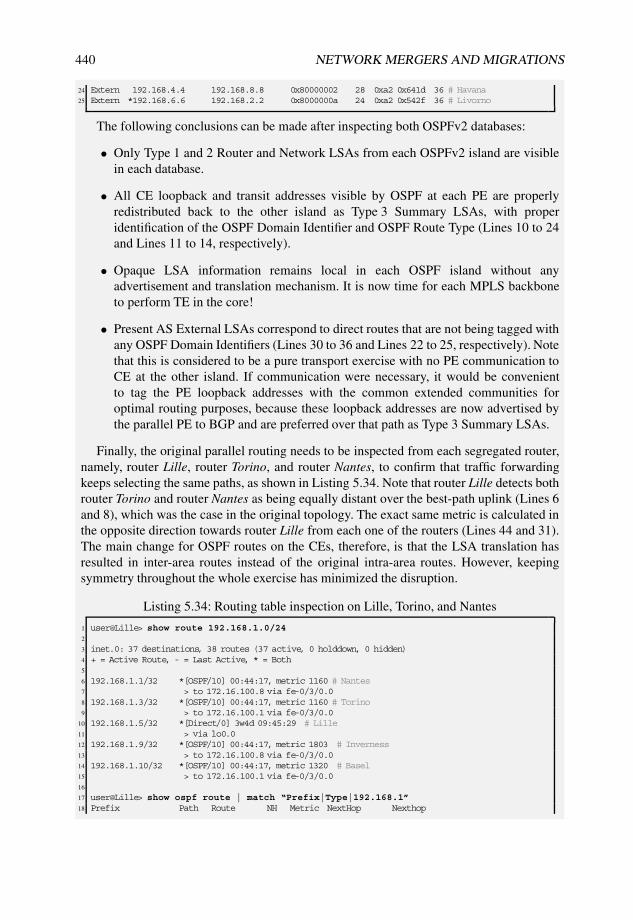
440 NETWORK MERGERS AND MIGRATIONS
24 Extern 192.168.4.4 192.168.8.8 0x80000002 28 0xa2 0x641d 36 # Havana25 Extern *192.168.6.6 192.168.2.2 0x8000000a 24 0xa2 0x542f 36 # Livorno
The following conclusions can be made after inspecting both OSPFv2 databases:
• Only Type 1 and 2 Router and Network LSAs from each OSPFv2 island are visiblein each database.
• All CE loopback and transit addresses visible by OSPF at each PE are properlyredistributed back to the other island as Type 3 Summary LSAs, with properidentification of the OSPF Domain Identifier and OSPF Route Type (Lines 10 to 24and Lines 11 to 14, respectively).
• Opaque LSA information remains local in each OSPF island without anyadvertisement and translation mechanism. It is now time for each MPLS backboneto perform TE in the core!
• Present AS External LSAs correspond to direct routes that are not being tagged withany OSPF Domain Identifiers (Lines 30 to 36 and Lines 22 to 25, respectively). Notethat this is considered to be a pure transport exercise with no PE communication toCE at the other island. If communication were necessary, it would be convenientto tag the PE loopback addresses with the common extended communities foroptimal routing purposes, because these loopback addresses are now advertised bythe parallel PE to BGP and are preferred over that path as Type 3 Summary LSAs.
Finally, the original parallel routing needs to be inspected from each segregated router,namely, router Lille, router Torino, and router Nantes, to confirm that traffic forwardingkeeps selecting the same paths, as shown in Listing 5.34. Note that router Lille detects bothrouter Torino and router Nantes as being equally distant over the best-path uplink (Lines 6and 8), which was the case in the original topology. The exact same metric is calculated inthe opposite direction towards router Lille from each one of the routers (Lines 44 and 31).The main change for OSPF routes on the CEs, therefore, is that the LSA translation hasresulted in inter-area routes instead of the original intra-area routes. However, keepingsymmetry throughout the whole exercise has minimized the disruption.
Listing 5.34: Routing table inspection on Lille, Torino, and Nantes
1 user@Lille> show route 192.168.1.0/242
3 inet.0: 37 destinations, 38 routes (37 active, 0 holddown, 0 hidden)4 + = Active Route, - = Last Active, * = Both5
6 192.168.1.1/32 *[OSPF/10] 00:44:17, metric 1160 # Nantes7 > to 172.16.100.8 via fe-0/3/0.08 192.168.1.3/32 *[OSPF/10] 00:44:17, metric 1160 # Torino9 > to 172.16.100.1 via fe-0/3/0.0
10 192.168.1.5/32 *[Direct/0] 3w4d 09:45:29 # Lille11 > via lo0.012 192.168.1.9/32 *[OSPF/10] 00:44:17, metric 1803 # Inverness13 > to 172.16.100.8 via fe-0/3/0.014 192.168.1.10/32 *[OSPF/10] 00:44:17, metric 1320 # Basel15 > to 172.16.100.1 via fe-0/3/0.016
17 user@Lille> show ospf route | match “Prefix|Type|192.168.1”18 Prefix Path Route NH Metric NextHop Nexthop

MPLS LAYER 3 VPN MIGRATIONS 441
19 Type Type Type Interface addr/label20 192.168.1.1/32 Inter Network IP 1160 fe-0/3/0.0 172.16.100.8 # Nantes21 192.168.1.3/32 Inter Network IP 1160 fe-0/3/0.0 172.16.100.1 # Torino22 192.168.1.5/32 Intra Network IP 0 lo0.023 192.168.1.9/32 Inter Network IP 1803 fe-0/3/0.0 172.16.100.8 # Inverness24 192.168.1.10/32 Inter Network IP 1320 fe-0/3/0.0 172.16.100.1 # Basel25
26 user@Torino> show route 192.168.1.527
28 inet.0: 33 destinations, 38 routes (33 active, 0 holddown, 0 hidden)29 + = Active Route, - = Last Active, * = Both30
31 192.168.1.5/32 *[OSPF/10] 00:46:46, metric 1160 # Lille32 > via at-0/0/1.033
34 user@Torino> show ospf route | match “Prefix|Type|192.168.1.5”35 Prefix Path Route NH Metric NextHop Nexthop36 Type Type Type Interface addr/label37 192.168.1.5/32 Inter Network IP 1160 at-0/0/1.0 # Lille38
39 user@Nantes> show route 192.168.1.540
41 inet.0: 36 destinations, 40 routes (36 active, 0 holddown, 0 hidden)42 + = Active Route, - = Last Active, * = Both43
44 192.168.1.5/32 *[OSPF/10] 00:48:06, metric 1160 # Lille45 > via so-0/1/0.046
47 user@Nantes> show ospf route | match “Prefix|Type|192.168.1.5”48 Prefix Path Route NH Metric NextHop Nexthop49 Type Type Type Interface addr/label50 192.168.1.5/32 Inter Network IP 1160 so-0/1/0.0 # Lille
This final setup is represented in Figure 5.25, which shows that the topology has finallyemulated the original uplinks for the legacy network over MPLS backbones keepingsymmetric and parallel costs, after carrying out smooth transitions first using sham linksfirst and then using proper LSA translation.
Nantes
Skopie
Livorno
Barcelona
Honolulu
192.168.1.1
192.168.1.2
192.168.1.6
192.168.1.7
192.168.1.21
Torino
Lille
192.168.1.9
InvernessBasel
192.168.1.5
192.168.1.3
192.168.1.10
Area 0.0.0.0
TE extensions
RSVP−TE
OSPF legacy network
Area 0.0.0.0
Domain "Cyclone"
MPLS BackboneOSPF PE−CE
Link Cost 160
Male
Bilbao
Havana192.168.1.4
192.168.1.20
192.168.1.8
Domain "Mistral"
MPLS Backbone
LDP
OSPF PE−CE
Link Cost 160
OSPF legacy site
Area 0.0.0.0
domain−id 64502:1
domain−id 64502:1
domain−id:64502:1
added to OSPF
redistributed routes
OSPF PE−CE
Link Cost 1000
OSPF PE−CE
Link Cost 1000
Figure 5.25: Stage nine: sham-link decommissioning over domain “Cyclone” and finalsetup.

442 NETWORK MERGERS AND MIGRATIONS
domain-vpn-tag
Junos OS complies with standard mechanisms defined in [RFC4576] and [RFC4577] withregard to the DN bit and VPN Route Tag by setting automatically derived values to be fullycompatible with earlier leak-prevention implementations that made use only of the VPNRoute Tag.
The domain-vpn-tag configuration knob allows the setting of specific External RouteTag values in Type 5 and 7 LSAs injected towards the CEs. This knob allows arbitrary valuesto be configured following certain administrative policies, for instance. Note that the value setwith the knob cannot be overridden with an additional OSPF export policy inside the VRF:domain-vpn-tag takes precedence and sets the definitive value for the External RouteTag field in Junos OS.
A standard scenario that makes use of this implementation is a PE multihomed topology inwhich route leaking towards the backbone is controlled by setting common or disjoint OSPFVPN Route Tags. For legacy PEs that may not understand the DN bit but do comply withprevious versions of [RFC4577], or when multihoming the setup to more than one MPLStransport backbone (with different AS numbers resulting in different default OSPF VPNRoute Tag values), this feature is tremendously helpful.
Another possible application is crafting an External Route Tag value with the domain-vpn-tag knob at the PEs. Legacy CEs that comply with [RFC1403], Section 4.4 for old-fashioned BGP-OSPF interaction can generate AS paths derived from the External Route Tagvalue further down the path as advertisements within EBGP sessions.
Despite the fact that the PE can mark the DN bit for all advertisements towards theCE domain, considering the topology from Figure 5.25, Listing 5.35 illustrates the changeson router Livorno and router Havana in a given redistributed AS External LSA afterimplementing a common VPN Route Tag. Note that the LSAs originally include defaultAS-derived values in the Tag field, as shown in Figure 5.4 on Lines 7 and 19. Also note thatthe configuration change automatically updates the field, as seen in Lines 31 and 39.
This change is not strictly needed to control route leaking because both routers mark theDN bit in the Options field prior to the change, as seen in Figure 5.3 and in Listing 5.35with the Options byte value “0xa2” including the DN bit marking, before the modification(Lines 4 and 16) and after it (Lines 30 and 38). This is considered here just to illustrate thebackward-compatible behavior.
Listing 5.35: Same VPN route tag configured in Livorno and Havana
1 user@Havana> show ospf database instance NMM lsa-id 172.16.1.100 extensive external2 OSPF AS SCOPE link state database3 Type ID Adv Rtr Seq Age Opt Cksum Len4 Extern *172.16.1.100 192.168.4.4 0x80000001 1860 0xa2 0x12ca 36 # DN bit set5 mask 255.255.255.2526 Topology default (ID 0)7 Type: 2, Metric: 0, Fwd addr: 0.0.0.0, Tag: 208.0.251.247 # AS-derived VPN Route Tag8 Gen timer 00:05:049 Aging timer 00:29:00
10 Installed 00:31:00 ago, expires in 00:29:00, sent 00:31:00 ago11 Last changed 00:31:00 ago, Change count: 1, Ours12
13 user@Livorno> show ospf database instance NMM lsa-id 172.16.1.0 external extensive14 OSPF AS SCOPE link state database15 Type ID Adv Rtr Seq Age Opt Cksum Len16 Extern *172.16.1.0 192.168.6.6 0x80000003 2647 0xa2 0xbb81 36 # DN bit set17 mask 255.255.255.252

MPLS LAYER 3 VPN MIGRATIONS 443
18 Topology default (ID 0)19 Type: 2, Metric: 0, Fwd addr: 0.0.0.0, Tag: 208.0.251.245 # AS-derived VPN Route Tag20 Gen timer 00:02:4521 Aging timer 00:15:5322 Installed 00:44:07 ago, expires in 00:15:53, sent 00:44:05 ago23 Last changed 01:33:31 ago, Change count: 1, Ours24
25 [edit routing-instances NMM protocols ospf]26 user@Havana# set domain-vpn-tag 6450227
28 user@Havana> show ospf database instance NMM lsa-id 172.16.1.100 extensive external |29 match “Extern|Tag:”30 Extern *172.16.1.100 192.168.4.4 0x80000002 63 0xa2 0xc3ea 36 # DN bit set31 Type: 2, Metric: 0, Fwd addr: 0.0.0.0, Tag: 0.0.251.246 # VPN Route Tag 6450232
33 [edit routing-instances NMM protocols ospf]34 user@Livorno# set domain-vpn-tag 6450235
36 user@Livorno> show ospf database instance NMM lsa-id 172.16.1.0 external extensive |37 match “Extern|Tag”38 Extern *172.16.1.0 192.168.6.6 0x80000004 46 0xa2 0x8f7c 36 # DN bit set39 Type: 2, Metric: 0, Fwd addr: 0.0.0.0, Tag: 0.0.251.246 # VPN route tag 64502
Another interesting corner case for controlling route leaking takes place when settingdomain-vpn-tag 0. This configuration has the following consequences:
• “Bleaching” (zeroing) of External Route Tag field on Type 5 and 7 LSAs;
• Untagging of DN bit in Options field on Type 5 and 7 LSAs.
To sum up, domain-vpn-tag 0 removes all distinguishers for PE–CE leaking fromany External LSA type and overrides the standard loop protection behavior on OSPFv2 CEdomains to allow redistribution through other PEs towards their backbone in the same setup.
Note that Type 3 Summary LSAs representing inter-area networks after translation are notaffected by this specific setting in Junos OS and keep the DN bit set after redistribution (thereis no such Route Tag field in Summary LSAs). It is understood that if a VPN-IPv4 route istranslated into a Type 3 Summary LSA, it belongs to the same domain (sharing the sameDomain Identifier between VPN sites).
It goes without saying that a smart network engineer must think more than twice beforeimplementing this knob, because it disables an implicit loop-prevention mechanism andopens a door for redistribution and forwarding issues!
Junos Tip: Inter-AS Option A based on OSPF Domain Identifier mismatch, DN bitand VPN Route Tag bleaching
[RFC4577] describes resources for using OSPF as a PE–CE communication protocol insidea VRF, but doing this certainly impedes PE–PE communication within a VRF (that isto say, with an inter-AS Option A interconnect) with the already discussed built-in loop-blocking mechanisms. This case certainly requires careful design and should also considerthe domain-flooding scope of OSPFv2 as a link-state routing protocol.
However, there can be some scenarios in which a network designer may need tointerconnect two MPLS backbones through an OSPF island inside a VPN site or to allowroute advertisement beyond a PE for the purpose of installing a backup path. In such setups,LSAs advertised towards the CE domain must cope with the following requirements:

444 NETWORK MERGERS AND MIGRATIONS
• DN bit must not be set;
• VPN Route Tag must not be the same across PEs.
The domain-vpn-tag 0 configuration allows bleaching of both the DN bit andTag field, but acts on Type 5 or Type 7 LSAs. If VPN sites belong to a common OSPFdomain, Type 3 LSAs (such as inter-area routes) are not affected by this change. Thismeans that an artificial OSPF Domain Identifier mismatch must be issued to force allroutes to be injected towards the attached CEs and PEs in the VPN site as external LSAs.While different OSPF Domain Identifier values can be configured at participating CEs, theadvantage of using domain-id disable is that it always and unilaterally detaches thePE from the backbone for that purpose, leading to the generation of Type 5 and Type 7LSAs, independent of any OSPF Domain Identifier, either null or any specific value, ofincoming routes.
Note that the bidirectional configuration imposed in Junos OS for setting (using exportpolicies) and matching (using the domain-id knob) OSPF Domain Identifiers also offersadditional possibilities for further tweaking of route advertisements, because a given PE cantag a specific OSPF Domain Identifier on exported routes while matching another value(or completely disabling Domain Identifier matching), thereby creating unidirectionalrules.
Consider a derivation from the well-known topology in Figure 5.25, in which it is nowdesired to have the CE segment shared among router Lille, router Livorno, and routerHavana also act as a backup path for domain “Cyclone” to reach VPN routes from theOSPFv2 legacy network.
By removing the Domain Identifier checks and bleaching the DN bit and VPN RouteTag fields on Havana, all received VPN-IPv4 routes are translated as AS External LSAsinside the VPN site, with the following actions:
• Because domain-id disable is set for incoming route checks, OSPF DomainIdentifiers from received routes are ignored and these routes are translated as eitherType 5 or Type 7 LSAs.
• Because the only Area configured in the VRF site is 0.0.0.0, the translation resultsinto Type 5 LSAs.
• The DN bit is not set and the VPN route tag is bleached as a result of thedomain-vpn-tag 0 configuration.
• Router Livorno imports those Type 5 LSAs for internal readvertisement to MP-BGPbecause none of the [RFC4577] loop-control mechanisms are set.
The configuration changes and effects on Havana are described in Listing 5.36.When comparing this listing with Listing 5.32, the expected changes introduced by theconfiguration changes become clearer: routes that were previously injected as Type 3Summary LSAs with matching OSPF Domain Identifiers and proper route translation(Lines 10 to 24 from Listing 5.32) are now visible as Type 5 AS External LSAs (Lines 18to 29 from Listing 5.36).

MPLS LAYER 3 VPN MIGRATIONS 445
Listing 5.36: Disabling Domain Identifier checks and DN bit and VPN route tagging onHavana
1 [edit routing-instances NMM protocols ospf]2 user@Havana# set domain-vpn-tag 03 [edit routing-instances NMM protocols ospf]4 user@Havana# set domain-id disable5
6 user@Havana> show ospf database instance NMM7
8 OSPF database, Area 0.0.0.09 Type ID Adv Rtr Seq Age Opt Cksum Len
10 Router 192.168.1.5 192.168.1.5 0x8000005c 12 0x22 0xe268 4811 Router *192.168.4.4 192.168.4.4 0x80000014 11 0x22 0x444b 4812 Router 192.168.6.6 192.168.6.6 0x80000011 12 0x22 0xc1bc 4813 Network 172.16.100.5 192.168.1.5 0x80000010 12 0x22 0x5bdf 3614 OpaqArea 1.0.0.1 192.168.1.5 0x80000036 1097 0x22 0x56c4 2815 OSPF AS SCOPE link state database16 Type ID Adv Rtr Seq Age Opt Cksum Len17 <...>18 Extern *172.16.1.72 192.168.4.4 0x80000001 11 0x22 0xc6b 3619 Extern *172.16.1.80 192.168.4.4 0x80000001 11 0x22 0x866e 3620 Extern *172.16.1.96 192.168.4.4 0x80000001 11 0x22 0xe5fe 3621 Extern *172.16.1.100 192.168.4.4 0x80000004 11 0x22 0x2cf2 3622 Extern *192.168.1.1 192.168.4.4 0x80000001 11 0x22 0x850f 36 # Nantes23 Extern *192.168.1.3 192.168.4.4 0x80000001 11 0x22 0x2c07 36 # Torino24 Extern *192.168.1.9 192.168.4.4 0x80000001 11 0x22 0x6a9c 36 # Inverness25 Extern *192.168.1.10 192.168.4.4 0x80000001 11 0x22 0x2b60 36 # Basel26 # Mgmt Loopback for Skopie27 Extern *192.168.2.2 192.168.4.4 0x80000001 11 0x22 0xb63b 3628 # Mgmt Loopback for Bilbao29 Extern *192.168.8.8 192.168.4.4 0x80000004 11 0x22 0x6064 36
Listing 5.37 reveals further details with regard to the data on the parallel PE in the samenetwork segment:
• Options and External Route Tag field are untagged (Options field “0x22” instead of“0xa2”) and bleached (Tag: 0.0.0.0) (for example, see Lines 12 and 13 for the ASExternal LSA representing router Nantes loopback);
• As a consequence, those routes from external LSAs are advertised internally in theMPLS backbone domain “Cyclone” towards other neighbors. As a curiosity, notethat the original OSPF metric cost is kept from the original translation and is passedto the next transformation into the VPN-IPv4 BGP route MED attribute value.
Listing 5.37: AS External LSA inspection and route advertisement on Livorno afterchanges on Havana
1 user@Livorno> show ospf database instance NMM external extensive2 | match “Extern|Tag”3 <...>4 Extern 172.16.1.72 192.168.4.4 0x80000001 161 0x22 0xc6b 365 Type: 2, Metric: 963, Fwd addr: 0.0.0.0, Tag: 0.0.0.06 Extern 172.16.1.80 192.168.4.4 0x80000001 161 0x22 0x866e 367 Type: 2, Metric: 320, Fwd addr: 0.0.0.0, Tag: 0.0.0.08 Extern 172.16.1.96 192.168.4.4 0x80000001 161 0x22 0xe5fe 369 Type: 2, Metric: 320, Fwd addr: 0.0.0.0, Tag: 0.0.0.0
10 Extern 172.16.1.100 192.168.4.4 0x80000004 161 0x22 0x2cf2 3611 Type: 2, Metric: 0, Fwd addr: 0.0.0.0, Tag: 0.0.0.012 Extern 192.168.1.1 192.168.4.4 0x80000001 161 0x22 0x850f 36 # Nantes13 Type: 2, Metric: 320, Fwd addr: 0.0.0.0, Tag: 0.0.0.014 Extern 192.168.1.3 192.168.4.4 0x80000001 161 0x22 0x2c07 36 # Torino15 Type: 2, Metric: 160, Fwd addr: 0.0.0.0, Tag: 0.0.0.0

446 NETWORK MERGERS AND MIGRATIONS
16 Extern 192.168.1.9 192.168.4.4 0x80000001 161 0x22 0x6a9c 36 # Inverness17 Type: 2, Metric: 963, Fwd addr: 0.0.0.0, Tag: 0.0.0.018 Extern 192.168.1.10 192.168.4.4 0x80000001 161 0x22 0x2b60 36 # Basel19 Type: 2, Metric: 320, Fwd addr: 0.0.0.0, Tag: 0.0.0.020 # Mgmt Loopback for Skopie21 Extern 192.168.2.2 192.168.4.4 0x80000001 161 0x22 0xb63b 3622 Type: 2, Metric: 480, Fwd addr: 0.0.0.0, Tag: 0.0.0.023 # Mgmt Loopback for Bilbao24 Extern 192.168.8.8 192.168.4.4 0x80000004 161 0x22 0x6064 3625 Type: 2, Metric: 0, Fwd addr: 0.0.0.0, Tag: 0.0.0.026
27 user@Livorno> show route advertising-protocol bgp 192.168.1.2 table NMM28
29 NMM.inet.0: 20 destinations, 34 routes (20 active, 0 holddown, 0 hidden)30 Prefix Nexthop MED Lclpref AS path31 <...>32 * 172.16.1.72/30 Self 963 100 I33 * 172.16.1.80/30 Self 320 100 I34 * 172.16.1.96/30 Self 320 100 I35 * 172.16.1.100/30 Self 0 100 I36 * 172.16.100.0/24 Self 100 I37 * 192.168.1.1/32 Self 320 100 I38 * 192.168.1.3/32 Self 160 100 I39 * 192.168.1.5/32 Self 481 100 I40 * 192.168.1.9/32 Self 963 100 I41 * 192.168.1.10/32 Self 320 100 I42 * 192.168.2.2/32 Self 480 100 I43 * 192.168.4.4/32 Self 481 100 I44 * 192.168.6.6/32 Self 100 I45 * 192.168.8.8/32 Self 0 100 I
This situation is illustrated in Figure 5.26.
Nantes
Skopie
Livorno
Barcelona
Honolulu
192.168.1.1
192.168.1.2
192.168.1.6
192.168.1.7
192.168.1.21
Torino
Lille
192.168.1.9
InvernessBasel
192.168.1.5
192.168.1.3
192.168.1.10
Area 0.0.0.0
TE extensions
RSVP−TE
OSPF legacy network
Area 0.0.0.0
Domain "Cyclone"
MPLS BackboneOSPF PE−CE
Link Cost 160
Male
Bilbao
Havana192.168.1.4
192.168.1.20
192.168.1.8Domain "Mistral"
MPLS Backbone
LDP
OSPF PE−CE
Link Cost 160
OSPF PE−CE Link Cost 1000
OSPF legacy site
Area 0.0.0.0
domain−id 64502:1
domain−id 64502:1
domain−id:64502:1
added to OSPF
redistributed routes
domain−id disable
domain−vpn−tag 0 Routes redistributed
as Type−5 LSAs
with DN bit untagged
and External route Tag 0
External Routes from
Type−5 LSAs
with DN bit untagged
and External route Tag 0
imported for MP−BGP redistribution
Figure 5.26: OSPF DN bit and VPN Route Tag bleaching, and Domain Identifier checkremoval at Havana.
In a nutshell, all other PEs participating in the same VPN at domain “Cyclone” can seetwo different active paths for the same original OSPF routes. It is a question of performingsome BGP TE as desired inside the domain to ensure that paths advertised from router

MPLS LAYER 3 VPN MIGRATIONS 447
Skopie are always preferred when present (this can be as simple as defining differentvrf-export policies to manipulate the BGP attributes).
On router Skopie, the default protocol preferences from Junos OS ensure that no routingloop is formed, because OSPF paths are always preferred over BGP paths from routerLivorno whenever they are present, as seen in Listing 5.38. Because all selected routes forleaking on router Havana are originally advertised as Type 1 or Type 2 LSAs, this alsoconfirms that no routing loops should be formed on router Skopie when transient routingchurn occurs, because intra-area routes are always preferred in OSPF over external routesas soon as they become present.
Listing 5.38: AS External LSA inspection and route advertisement on Livorno afterchanges on Skopie
1 user@Skopie> show route table NMM | no-more2
3 NMM.inet.0: 20 destinations, 35 routes (20 active, 0 holddown, 0 hidden)4 + = Active Route, - = Last Active, * = Both5
6 <...>7 192.168.1.1/32 *[OSPF/10] 10:14:04, metric 160 # Nantes8 > via so-0/1/0.09 [BGP/170] 00:03:24, MED 320, localpref 100, from 192.168.1.6
10 AS path: I11 > via so-1/0/0.0, label-switched-path Skopie-to-Livorno12 192.168.1.3/32 *[OSPF/10] 10:14:04, metric 320 # Torino13 > via so-0/1/0.014 [BGP/170] 00:03:24, MED 160, localpref 100, from 192.168.1.615 AS path: I16 > via so-1/0/0.0, label-switched-path Skopie-to-Livorno17 192.168.1.5/32 *[BGP/170] 00:07:54, MED 481, localpref 100, from 192.168.1.6 # Lille18 AS path: I19 > via so-1/0/0.0, label-switched-path Skopie-to-Livorno20 <...>21 192.168.8.8/32 *[OSPF/10] 02:05:39, metric 480 # Bilbao mgmt loopback22 > via so-0/1/0.023 [BGP/170] 00:06:19, MED 0, localpref 100, from 192.168.1.624 AS path: I25 > via so-1/0/0.0, label-switched-path Skopie-to-Livorno26 224.0.0.5/32 *[OSPF/10] 10:15:32, metric 127 MultiRecv
To be clear, this exercise has focused on route leaking in one direction for simplicity.Most applications require bidirectional flows, and thus a similar exercise should beperformed in the other direction if required by the service (for example, similardomain-id disable and domain-vpn-tag 0 in router Livorno for reverse backuppaths).
Junos Tip: Controlling route propagation from a CE with the VPN Route Tag
Another interesting application related to VPN Route Tags appears when considering theOSPFv2 protocol resources that [RFC4577] and [RFC4576] are reutilizating for PE–CEcommunications:
• DN bit reuses the high-order bit of the LSA Options field, which is unused as per[RFC2328], Section A.2.

448 NETWORK MERGERS AND MIGRATIONS
• VPN Route Tag reuses the 32-bit External Route tag that [RFC2328], Section A.4.5described to be used to propagate information across a domain.
Thus, the External Route Tag field is available to any router participating in OSPFv2,because the tag was designed for administrative tagging. On the other hand, [RFC4577]requests that any participating PE check and overwrite this field for backward-compatibilitypurposes if it detects a loop.
To briefly summarize, any participating CE can influence MP-BGP route redistributionfor locally originated Type 5 and Type 7 LSAs by setting external tags to match those fromselected PEs! This ability provides another indirect route advertisement mechanism thatremains external to the PEs and allows further possibilities for VPN customers to influencerouting in an MPLS backbone.
Consider another variation of the scenario in Figure 5.25, in which router Inverness as aCE is externally injecting 192.168.90.0/24 by means of a Type 5 LSA. The prerequisite inthis case is that traffic towards that destination uniquely flows through domain “Mistral”.Although this can be controlled on PEs with OSPFv2 import or vrf-export policies,it is requested that such TE be remotely controlled by the CE and be kept transparent to thePE configuration.
By making use of the mechanism described in this Junos Tip, router Inverness couldcraft the External Route Tag field in the Type 5 LSA for 192.168.90.0/24 so that it matchesthe VPN Route Tag from domain “Cyclone” so that this LSA is rejected in that domain,but is kept for legitimate redistribution to MP-BGP at domain “Mistral”.
Assuming default VPN Route Tag values in this scenario, derived from the AS numberas shown in Figure 5.4, router Inverness needs to set a decimal value of 3489725429 in theExternal Route Tag field to cause the VPN Route Tag to have the value corresponding to AS64501.This can be controlled simply with the OSPFv2 export policy on router Inverness,as shown in Listing 5.39, because the tag-setting action of the policy not only modifies theinternal route attribute in the routing table, but also sets the External Route Tag field withthat value in case it is exported into any type of AS external LSAs, as shown in Line 14.
Listing 5.39: External route tag setting on Inverness matching domain “Cyclone” VPNroute tag
1 [edit policy-options policy-statement NMM-static-to-ospf]2 user@Inverness# show3 term static {4 from protocol static;5 then {6 tag 3489725429; # External Route Tag value matching ‘‘Cyclone’’ domain’s VPN Route Tag7 accept;8 }9 }
10 user@Inverness> show ospf database instance NMM external lsa-id 192.168.90.011 extensive | match “Extern|Tag”12 Extern 192.168.90.0 192.168.1.9 0x80000001 130 0x22 0x6751 3613 Type: 2, Metric: 0, Fwd addr: 0.0.0.0, Tag: 208.0.251.24514 # ‘‘Cyclone’’ domain’s VPN Route Tag
Once the crafted Type 5 LSA is originated on router Inverness, which is an ASBR,routing table inspection on both PEs, router Bilbao and router Skopie, shows that despitedetecting the Type 5 LSA, the corresponding route is installed only on router Bilbao,which selects it for redistribution as a VPN-IPv4 route. The route is not even installed

MPLS LAYER 3 VPN MIGRATIONS 449
on router Skopie, which considers that the matching VPN Route Tag indicates that theroute is an already leaked route into OSPFv2 and thus assumes that an MP-BGP path forit should also be available. This is illustrated in Listing 5.40 for both router Bilbao androuter Skopie, which shows that no route-matching occurs on router Skopie and also showshow the VPN-IPv4-redistributed route is advertised by router Bilbao with the proper OSPFDomain Identifier and OSPF Route Type (Line 26).
Listing 5.40: OSPPFv2 database and routing table inspection on Bilbao and Skopie for thecrafted external route from Inverness
1 user@Bilbao-re0> show ospf database instance NMM external lsa-id 192.168.90.02 extensive3 OSPF AS SCOPE link state database4 Type ID Adv Rtr Seq Age Opt Cksum Len5 Extern 192.168.90.0 192.168.1.9 0x80000001 24 0x22 0x6751 366 mask 255.255.255.07 Topology default (ID 0)8 Type: 2, Metric: 0, Fwd addr: 0.0.0.0, Tag: 208.0.251.2459 Aging timer 00:59:36
10 Installed 00:00:21 ago, expires in 00:59:3611 Last changed 00:00:21 ago, Change count: 112
13 user@Bilbao-re0> show route advertising-protocol bgp 192.168.1.4 192.168.90.014 extensive15 # Route selected for MP-BGP redistribution16 NMM.inet.0: 21 destinations, 22 routes (21 active, 0 holddown, 0 hidden)17 * 192.168.90.0/24 (1 entry, 1 announced) # External route from Inverness18 BGP group IBGP type Internal19 Route Distinguisher: 64503:6450320 VPN Label: 1621 Nexthop: Self22 Flags: Nexthop Change23 MED: 024 Localpref: 10025 AS path: [64503] I26 Communities: target:64503:64503 domain-id:64502:1 rte-type:0.0.0.0:5:127 # Extended Communities referring to Type 5 LSA28
29 user@Skopie> show ospf database instance NMM external lsa-id 192.168.90.0 extensive30 OSPF AS SCOPE link state database31 Type ID Adv Rtr Seq Age Opt Cksum Len32 Extern 192.168.90.0 192.168.1.9 0x80000001 130 0x22 0x6751 3633 mask 255.255.255.034 Topology default (ID 0)35 Type: 2, Metric: 0, Fwd addr: 0.0.0.0, Tag: 208.0.251.24536 Aging timer 00:57:5037 Installed 00:02:08 ago, expires in 00:57:5038 Last changed 00:02:08 ago, Change count: 139
40 user@Skopie> show route 192.168.90.0/24 exact table NMM41 # No matches on the external route42 user@Skopie>
This example has considered a scenario with two different MPLS backbones. However,in the case of a joint core providing transit services, the same objective can be easilyachieved by setting different VPN Route Tags on redundantly connected PEs.
Route-Type-community
[RFC4577] recommends using the 2-byte type field 0x306 value to represent the OSPF RouteType attribute, and at the time of this writing, [IANA-extended-communities] assigns thesame value to OSPF Route Type extended communities.

450 NETWORK MERGERS AND MIGRATIONS
Previous implementations of the OSPF Route Type attribute were based on a differentvalue for the 2-byte type field: 0x8000. [RFC4577] states that this value should also beaccepted for backwards compatibility. From a network integration perspective, the challengeis to get legacy devices that implement earlier versions of [RFC4577] to properly understandthe OSPF Route Type from other VPN locations. In this case, use of this previous valuemay be required until heterogeneous support is confirmed across all PEs that are members ofthe VPN.
Junos OS supports the arbitrary setting of one or the other extended community typevalues, as shown in Listing 5.41.
Listing 5.41: Configuration options for the extended route type community for compatibilitypurposes
1 [edit routing-instances NMM protocols ospf]2 user@Livorno# set route-type-community ?3 Possible completions:4 iana BGP extended community value used is 0x03065 vendor Vendor BGP extended community value used is 0x8000
5.5.3 BGP PE–CE resources
Considering BGP as the most scalable, and probably most used, protocol for PE–CEcommunication, Junos OS is specifically committed to extend all plain BGP features thatcan be configured in the main routing instance so that they can also be configured within aVRF where applicable.
Section 3.5 describes the most relevant BGP features for migrations. It is worth consider-ing some of them again from the perspective of using them for PE–CE communication.
local-as
Section 3.5.2 describes the wide range of available commands in Junos OS to manipulateAS insertion in the AS_PATH. The local-as knob in Junos OS allows an externalrepresentation of a different AS for peers when negotiating and establishing BGP sessions,with several related suffixes to steer AS_PATH creation. Those resources are also availableinside a VRF in Junos OS and therefore can be used for scenarios with EBGP as the PE–CEprotocol.
This flexible handling of ASs allows for administrative manipulation of a givenAS_PATH, in which ASs can be artificially inserted, expanded, or suppressed. From allavailable options included in Section 3.5.2, two are particularly relevant for an environmentwith EBGP as the PE–CE protocol and transport over an MPLS backbone:
• local-as private keeps the local-as for BGP session handling and routeadvertisement towards peers, but this AS is suppressed from AS_PATHs towards thebackbone. This allows the AS identified with the local-as command in the VRFfor AS_PATHs to be stripped from routes advertised towards the backbone;
• local-as no-prepend-global-as does not include the global AS numberwhen advertising routes out of the network. This allows the AS corresponding to theMPLS transport backbone for AS_PATHs to be stripped from routes advertised towardsthe CE. Note that the local-as value configured in the VRF BGP session remainspresent in the AS_PATH; only the MPLS transport AS is suppressed.

MPLS LAYER 3 VPN MIGRATIONS 451
By selecting these local-as options, arbitrary AS numbers can be suppressed fromthe AS_PATH and transit through the MPLS core AS can remain hidden from the CE,allowing utilization of arbitrary AS_PATH policies just based on CE domain ASs for trafficengineering.
Junos Tip: Integrate route distribution into a L3VPN without prepending thetransport AS
A combination of local-as private and local-as no-prepend-global-asallows the suppression of ASs of the transport backbones and VRF local-as values forAS_PATHs transmitted upstream to the backbone.
The local-as feature provides a clear benefit when the intent is to keep routedistribution between ASs transparent for transport through an MPLS service provider.A migration scenario in which a legacy network that bases customer and service routeredistribution on a given interaction of EBGP sessions can also make use of this featureas part of being integrated into a L3VPN. It is also feasible to inject other prefixes intoone or another VRF site, thus avoiding the insertion of the MPLS backbone AS, and withor without a minimal need to manipulate BGP policies on any of the legacy routers, nowconsidered CEs in this scenario. This L3VPN can act both as a replacement for the olddirect EBGP interconnect and also as an uplink for routes from other sites.
With the network topology set up as defined in Figure 5.27, considering a full IBGPmesh on some routers and simultaneous EBGP sessions to router Lille on router Nantes androuter Torino, one of the backdoors is going to be migrated to become part of a L3VPN.
The exchanged BGP routes are considered the main focus for the migration,and it is considered essential that they are kept independent of the transit throughthe service provider. In fact, router Nantes implements some TE policies based onas-path-prepend twice with its own AS for routes further from router Torino androuter Basel, and router Torino does the same for router Nantes and router Inverness.
Lille
Nantes
192.168.1.5
so−0/1/0.0
172.
16.1
.24/
30
so−1/0/0.0
192.168.1.1Torino
192.168.1.9InvernessBasel
192.168.1.3
so−1/0/1.0
172.16.1.28/30
so−0/1/0.0
at−1/2/0.1001
at−0/0/0.1001
172.1
6.1
.80/3
0
172.11.1.96/30
at−0/1/0.1001
192.168.1.10at−0/1/0.1001
172.16.1.72/30
172.1
6.1
.64/3
0so−0/0/1.0
so−1/0/1.0
so−0/1/1.0
so−0/2/0.0
IBGP Full Mesh
AS 64502
OSPF Area 0.0.0.0
BGP 192.168.100.0/24
BGP 192.168.30.0/24
BGP 192.168.50.0/24
BGP 192.168.90.0/24
BGP 192.168.10.0/24
EBGP
AS 65550
EBGP EBGP as−path−prepend x2 64502
192.168.100.0/24
192.168.30.0/24
as−path−prepend x2 64502
192.168.90.0/24
192.168.10.0/24
Figure 5.27: Representative legacy BGP network to be integrated in a L3VPN.

452 NETWORK MERGERS AND MIGRATIONS
Listing 5.42 depicts the routing table including AS_PATH for each of the receivedroutes. With this setup, route transit over the L3VPN leads to a modification in the TEstrategies due to additional ASs that could appear in the AS_PATH, including, amongothers, the one for the MPLS backbone.
Listing 5.42: Initial BGP routing table on Lille prior to L3VPN integration
1 user@Lille> show route protocol bgp terse table inet.02
3 inet.0: 24 destinations, 29 routes (24 active, 0 holddown, 0 hidden)4 + = Active Route, - = Last Active, * = Both5
6 A Destination P Prf Metric 1 Metric 2 Next hop AS path7 * 192.168.10.0/24 B 170 100 >172.16.1.25 64502 I8 B 170 100 >172.16.1.29 64502 64502 64502 I9 * 192.168.30.0/24 B 170 100 >172.16.1.29 64502 I
10 B 170 100 >172.16.1.25 64502 64502 64502 I11 * 192.168.90.0/24 B 170 100 >172.16.1.25 64502 I12 B 170 100 >172.16.1.29 64502 64502 64502 I13 * 192.168.100.0/24 B 170 100 >172.16.1.29 64502 I14 B 170 100 >172.16.1.25 64502 64502 64502 I15
By making use of the local-as private and the no-prepend-global-asconfiguration options when integrating one of the uplinks as part of the L3VPN, only thefinal local-as for the egress VRF is added to the AS_PATH when advertising routes tothe CE.
A migration scenario using both commands is conceivable when interconnecting PEswith router Nantes and router Lille, as shown in Figure 5.28.
Nantes
Skopie
Livorno
Barcelona
Honolulu
192.168.1.1
192.168.1.2
192.168.1.6
192.168.1.7
192.168.1.21
Torino
Lille
192.168.1.9
Inverness
Basel
192.168.1.5
192.168.1.3
192.168.1.10
Area 0.0.0.0
TE extensions
RSVP−TE
Domain "Cyclone"
MPLS Backbone
AS 64501
EBGP
PE−CE
BGP 192.168.100.0/24
BGP 192.168.90.0/24
BGP 192.168.30.0/24
BGP 192.168.10.0/24
BGP 192.168.50.0/24
EBGP PE−CE
IBGP Full Mesh internal
AS 64502
OSPF Area 0.0.0.0
local−as 65550
private
no−prepend−global−as
EBGP
EBGP
as−path−prepend x2 64502
192.168.100.0/24
192.168.30.0/24as−path−prepend x2 64502
192.168.90.0/24
192.168.10.0/24
local−as 64502
private
no−prepend−global−as
AS 65550
Figure 5.28: Interconnect domain “Cyclone” PEs with router Lille and router Nantes.

MPLS LAYER 3 VPN MIGRATIONS 453
Listing 5.43 shows the configuration changes needed on Livorno, one of the PEs, toactivate the local-as private and the no-prepend-global-as together withEBGP peering towards router Lille. It is worth noting the following items:
• The no-prepend-global-as option is active on the local AS used with theCE (64502), which is still used for BGP session establishment and control purposes(Line 10).
• Advertised routes towards the CE do not include the MPLS backbone provider AS(64501) because of the no-prepend-global-as knob (Line 15).
• Router Lille selects backup paths for destinations over the L3VPN instead of fromrouter Torino (Line 22).
Listing 5.43: EBGP routes and no-prepend-global-as configuration in router Livorno androuter Lille
1 [edit routing-instances NMM protocols bgp]2 user@Livorno# show3 group EBGP-PE-CE {4 type external;5 local-address 172.16.100.8;6 family inet {7 unicast;8 }9 peer-as 65550;
10 local-as 64502 private no-prepend-global-as; # Private and no-prepend-global-as11 neighbor 172.16.100.5;12 }13
14 user@Livorno> show route advertising-protocol bgp 172.16.100.5 table NMM15 # AS 64501 not included in AS_PATH16 NMM.inet.0: 7 destinations, 12 routes (7 active, 0 holddown, 0 hidden)17 Prefix Nexthop MED Lclpref AS path18 * 192.168.10.0/24 Self 64502 I19 * 192.168.90.0/24 Self 64502 I20
21 user@Lille> show route protocol bgp terse table inet.022 # Backup paths for preferred routes over L3VPN instead of Torino23 inet.0: 24 destinations, 33 routes (24 active, 0 holddown, 0 hidden)24 + = Active Route, - = Last Active, * = Both25
26 A Destination P Prf Metric 1 Metric 2 Next hop AS path27 * 192.168.10.0/24 B 170 100 >172.16.1.25 64502 I28 B 170 100 >172.16.100.8 64502 64502 I # Over VPN29 B 170 100 >172.16.1.29 64502 64502 64502 I30 * 192.168.30.0/24 B 170 100 >172.16.1.29 64502 I31 B 170 100 >172.16.1.25 64502 64502 64502 I32 B 170 100 >172.16.100.8 64502 64502 64502 I # Over VPN33 * 192.168.90.0/24 B 170 100 >172.16.1.25 64502 I34 B 170 100 >172.16.100.8 64502 64502 I # Over VPN35 B 170 100 >172.16.1.29 64502 64502 64502 I36 * 192.168.100.0/24 B 170 100 >172.16.1.29 64502 I37 B 170 100 >172.16.1.25 64502 64502 64502 I38 B 170 100 >172.16.100.8 64502 64502 64502 I # Over VPN
Paths through the L3VPN are now eligible to become active after the direct backdoorbetween router Lille and router Nantes is disconnected.
When using both local-as private and no-prepend-global-as com-mands, not all ASs can be suppressed from AS_PATHs. The local-as corresponding
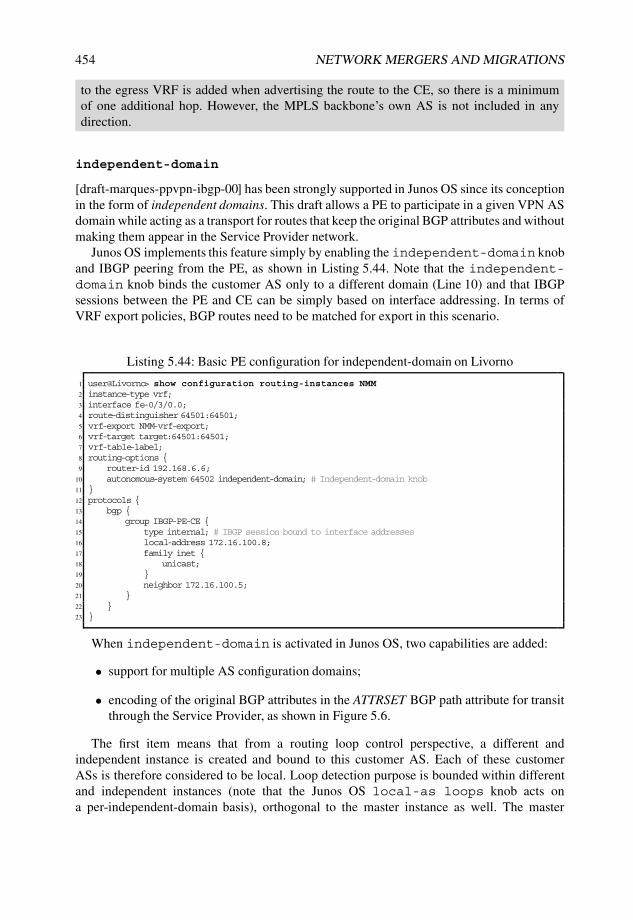
454 NETWORK MERGERS AND MIGRATIONS
to the egress VRF is added when advertising the route to the CE, so there is a minimumof one additional hop. However, the MPLS backbone’s own AS is not included in anydirection.
independent-domain
[draft-marques-ppvpn-ibgp-00] has been strongly supported in Junos OS since its conceptionin the form of independent domains. This draft allows a PE to participate in a given VPN ASdomain while acting as a transport for routes that keep the original BGP attributes and withoutmaking them appear in the Service Provider network.
Junos OS implements this feature simply by enabling the independent-domain knoband IBGP peering from the PE, as shown in Listing 5.44. Note that the independent-domain knob binds the customer AS only to a different domain (Line 10) and that IBGPsessions between the PE and CE can be simply based on interface addressing. In terms ofVRF export policies, BGP routes need to be matched for export in this scenario.
Listing 5.44: Basic PE configuration for independent-domain on Livorno
1 user@Livorno> show configuration routing-instances NMM2 instance-type vrf;3 interface fe-0/3/0.0;4 route-distinguisher 64501:64501;5 vrf-export NMM-vrf-export;6 vrf-target target:64501:64501;7 vrf-table-label;8 routing-options {9 router-id 192.168.6.6;
10 autonomous-system 64502 independent-domain; # Independent-domain knob11 }12 protocols {13 bgp {14 group IBGP-PE-CE {15 type internal; # IBGP session bound to interface addresses16 local-address 172.16.100.8;17 family inet {18 unicast;19 }20 neighbor 172.16.100.5;21 }22 }23 }
When independent-domain is activated in Junos OS, two capabilities are added:
• support for multiple AS configuration domains;
• encoding of the original BGP attributes in the ATTRSET BGP path attribute for transitthrough the Service Provider, as shown in Figure 5.6.
The first item means that from a routing loop control perspective, a different andindependent instance is created and bound to this customer AS. Each of these customerASs is therefore considered to be local. Loop detection purpose is bounded within differentand independent instances (note that the Junos OS local-as loops knob acts ona per-independent-domain basis), orthogonal to the master instance as well. The master

MPLS LAYER 3 VPN MIGRATIONS 455
independent-domain instance includes all other local ASs including its own and those ASsdefined in instances without the independent-domain knob.
Indirectly, this means that any local-as information that may be included in a givenstanza is domain-specific and relevant only for AS_PATH loop-detection purposes insidethat independent domain. Thus, if a route migrates across these AS-path domains using rib-groups or auto-export, it is necessary to perform AS prepending on the AS_PATH as if itwere a virtual EBGP session between the domains to ensure that the AS_PATH is correct andconsistent for loop detection.
From a migration perspective, independent-domain provides a twofold benefit:
• Service Providers can transport customer routes without their AS being present in thecustomer routes’ AS_PATH.
• Original BGP attributes are kept without need for specific policies on PEs.
Both these items are key distinguishers for this feature because they make customer BGPpolicies and TE almost completely transparent and independent from the transport throughthe Service Providers. Interim scenarios in which a given AS shares transit through traditionalInternet peering and an MPLS L3VPN, or transition topologies in which the intent is notto modify the original BGP attributes can benefit greatly from this concept because theyallow end customers to steer traffic directly without any further interaction with the transitprovider.
Application Note: Integrating route distribution and attributes into anL3VPN with independent domains
Because the independent-domain knob allows transparent forwarding of the originalBGP attributes from a given CE, a migration scenario in which a legacy network that basescustomer and service route redistribution on any arbitrary BGP mesh can benefit fromthis feature to migrate backdoor links into a L3VPN and therefore disseminate routinginformation over different networks, even across more than one MPLS backbone.
While this feature can act as a transparent replacement for a backdoor link, themain advantage of an implementation based on an L3VPN (as opposed to a parallelimplementation with any L2VPN or VPLS flavor) is that other routes from remote VPNsites can be granularly controlled for VRF import and therefore multiplexed with theexisting replacement. In a nutshell, a traditional L3VPN can also act as a transparentsubstitute for a backdoor link from another network.
If application flows are based on BGP routes, it is not strictly necessary to interact withany IGP from the PE, but only directly with BGP. The independent-domain featureallows the original TE attributes to be kept from the CEs while encapsulating traffic insidean MPLS L3VPN.
Consider our well-known topology constructed as shown in Figure 5.29 with an originalfull IBGP mesh among participating routers based on a common OSPFv2 backbone inwhich each device externally peers with another customer AS with plain unicast IPv4routes, importing them with their respective BGP attributes. The migration goal is todismantle both backdoor links between router Lille and router Nantes, and router Lille and

456 NETWORK MERGERS AND MIGRATIONS
router Torino, while integrating the transit together with other routes into a given L3VPNin a smooth and non-intrusive fashion.
Lille
Nantes
192.168.1.5
so−0/1/0.0
172.
16.1
.24/
30
so−1/0/0.0
192.168.1.1
Torino
192.168.1.9
InvernessBasel
192.168.1.3
so−1/0/1.0
172.1
6.1
.28/3
0
so−0/1/0.0
at−1/2/0.1001
at−0/0/0.1001172.1
6.1
.80/3
0
172.11.1.96/30
at−0/1/0.1001192.168.1.10
at−0/1/0.1001
172.16.1.72/30
172.1
6.1
.64/3
0so−0/0/1.0
so−1/0/1.0
so−0/1/1.0
so−0/2/0.0
IBGP Full Mesh
AS 64502OSPF Area 0.0.0.0
BGP 192.168.100.0/24
local−preference 100
MED 100
AS path: 64510
BGP 192.168.30.0/24
local−preference 30
MED 30
AS path: 64503
BGP 192.168.50.0/24
local−preference 50
MED 50
AS path: 64505
BGP 192.168.90.0/24
local−preference 90
MED 90
AS path: 64509
BGP 192.168.10.0/24
local−preference 10
MED 10
AS path: 64510
EBGP
EBGP
EBGP
EBGP
EBGP
Figure 5.29: Representative legacy IBGP full-mesh network to be integrated in a L3VPN.
These routes represent customer address space and sensitive applications and are themain focus of the integration. Therefore, it is considered vital to maintain all BGP attributesfrom the original end customer ASs so as not to change the original TE policies on therouters, and it is assumed that physical transits are derived over the new PEs. There is alsoa certain risk that traffic-engineering policies from the transport Service Provider mightoverlap those from the original domain.
Because each participating router in the original full mesh injects the exter-nal routes with a different LOCAL_PREFERENCE, MED, and AS_PATH, theindependent-domain feature becomes the perfect fit for transporting them ina scalable fashion without requiring crafted policies on the transport domain PEs.Independent domains directly skip any potential conflicts because the transport TE policiesare therefore based on BGP attributes attached to the internal VPN-v4 NLRIs rather thanon the encapsulated attributes in the ATTRSET.
Figure 5.30 illustrates the objective scenario in which router Lille is physically isolatedfrom the original backbone, but remains connected and integrated into a joint L3VPN thatis used as a transparent transport.

MPLS LAYER 3 VPN MIGRATIONS 457
Nantes
Skopie
Livorno
Barcelona
Honolulu
192.168.1.1
192.168.1.2
192.168.1.6
192.168.1.7
192.168.1.21
Torino
Lille
192.168.1.9
Inverness
Basel
192.168.1.5
192.168.1.3
192.168.1.10
Area 0.0.0.0
TE extensions
RSVP−TE
IBGP Full Mesh
AS 64502
OSPF
Area 0.0.0.0
Domain "Cyclone"
MPLS Backbone
IBGP PE−CE
IBGP redistribution
to and from VPN−IPv4 routes
Original customer
BGP attributes are kept
IBGP PE−CE
MP−BGP
family inet−vpn unicast
IBGP Site
AS 64502
BGP 192.168.100.0/24
local−preference 100
MED 100
AS path: 64510BGP 192.168.90.0/24
local−preference 90
MED 90
AS path: 64509
BGP 192.168.30.0/24
local−preference 30
MED 30
As path: 64503 BGP 192.168.10.0/24
local−preference 10
MED 10
AS path: 64501
BGP 192.168.50.0/24
local−preference 50
MED 50
AS path: 64505
EBGP
EBGP
EBGP
EBGP
EBGP
Figure 5.30: Migrated legacy IBGP full-mesh network over a L3VPN.
A global configuration and routing table overview is provided in Listing 5.45 fromrouter Lille’s perspective, including IGP metrics to each of the other peers in the network,and the MED and local-preference values as designed.
Listing 5.45: Initial BGP configuration and routing table on Lille prior to L3VPNintegration
1 user@Lille> show configuration protocols bgp group IBGP2 type internal;3 local-address 192.168.1.5;4 family inet {5 unicast;6 }7 export redist-static;8 neighbor 192.168.1.1; # Nantes9 neighbor 192.168.1.3; # Torino
10 neighbor 192.168.1.10; # Basel11 neighbor 192.168.1.9; # Inverness12
13 user@Lille> show route protocol bgp table inet.0 extensive |14 match “entr|Protocol next hop|Localpref|metric|AS path”15 192.168.10.0/24 (1 entry, 1 announced) # Address space from Nantes16 Protocol next hop: 192.168.1.117 Age: 2:56 Metric: 10 Metric2: 643 # Local preference and MED from Nantes18 AS path: 64501 I19 Localpref: 1020 Protocol next hop: 192.168.1.1 Metric: 64321 Metric: 643 Node path count: 122 192.168.30.0/24 (1 entry, 1 announced) # Address space from Torino

458 NETWORK MERGERS AND MIGRATIONS
23 Protocol next hop: 192.168.1.324 Age: 4:06 Metric: 30 Metric2: 643 # Local preference and MED from Torino25 AS path: 64503 I26 Localpref: 3027 Protocol next hop: 192.168.1.3 Metric: 64328 Metric: 643 Node path count: 129 <...>30 192.168.90.0/24 (1 entry, 1 announced) # Address space from Inverness31 Protocol next hop: 192.168.1.932 Age: 6:37 Metric: 90 Metric2: 1286 # Local preference and MED from Inverness33 AS path: 64509 I34 Localpref: 9035 Protocol next hop: 192.168.1.9 Metric: 128636 Metric: 1286 Node path count: 137 192.168.100.0/24 (1 entry, 1 announced) # Address space from Basel38 Protocol next hop: 192.168.1.1039 Age: 2:27 Metric: 100 Metric2: 803 # Local preference and MED from Basel40 AS path: 64510 I41 Localpref: 10042 Protocol next hop: 192.168.1.10 Metric: 80343 Metric: 803 Node path count: 144
Continuing with the migration requires that the native uplinks from router Lille bereplaced with the transit interconnect to router Livorno, and within the same L3VPN, routerNantes is migrated to router Skopie.
Compared with previous migration setups, the focus is BGP route advertisement. Itis assumed that newer transits lead to a different forwarding behavior, but inter-AS TEpolicies must remain the same. In this case, the BGP route advertisement must retain thesame attributes and criteria.
A first legitimate consideration is the BGP virtual topology into which the PEs need tobe inserted. Figure 5.29 represents a full IBGP mesh among routers with no specific routereflection. Indirectly, inserting a PE with independent-domain means that routesreceived from a CE are readvertised to the backbone, and vice versa, so reflection isperformed using IBGP and with no specific BGP attributes related to BGP route reflection.While the intent is actually to include the reflection in this migration, PEs need to be ableto gather all IBGP routes from each VPN site in which they participate.
Although router Lille as a standalone segregated site can receive all routes from routerLivorno without further propagation down the path to any IBGP peer, only router Nantesis physically connected to router Skopie at the remaining major site.
The traditional IBGP reflection paradigm for how to mesh routers or reflect routes ispresented here. In a simplistic fashion, two alternatives are available for this major VPNsite:
• Route Reflection: directly attached CE (router Nantes) performs route reflectiontowards the PE (router Skopie).
• Full mesh: PE (router Skopie) is fully meshed with all CEs (router Nantes, routerTorino, router Inverness and router Basel) in the final VPN site.
Next-hop reachability is also a legitimate concern. [draft-marques-ppvpn-ibgp-00]imposes a next-hop substitution when advertising routes from the PE to the CE andextracting the original attributes from the transport ATTRSET.

MPLS LAYER 3 VPN MIGRATIONS 459
Depending on the selected virtual BGP topology into which router Skopie gets meshed,the original next hop may or may not need to be advertised:
• Route reflection: router Nantes performs the next-hop rewrite together with routereflection towards router Skopie and towards the rest of the domain.
• Full mesh: either router Skopie is engaged in the internal IGP or bidirectionalreachability is ensured not only with router Nantes but also with other routers atthe major site.
The first option is based on [RFC4456] route reflection and presents the advantage ofinserting a clear demarcation point at the PE boundary to the directly attached CEs, withoutinfluencing any other internal routers in the major VPN island. Router Skopie does notneed to participate in the corresponding IGP or make its BGP next hop reachable beyondrouter Nantes, which even allows for address overlapping with that transit interface. Amain disadvantage is that router Nantes becomes a route reflector server with router Skopiebeing its client, requiring a next-hop change in each direction and inserting additionalattributes inherent to route reflection, as per [RFC4456], that are not present in the originalpath: ORIGINATOR_ID and CLUSTER_LIST. Their influence is not only limited to loopdetection, but CLUSTER_LIST length is also considered in Junos OS as a route selectiontie-breaker at some point.
The second option does not attach any further BGP attributes to the original routes,keeping the root Attribute-Set, but requires further protocol manipulation on router Skopieand eventually, router Nantes. In fact, router Skopie gets fully inserted in the major VPNisland IBGP mesh, which poses a challenge of proper next-hop reachability. This requiresthat either router Skopie participates in the IGP as well, or that equivalent bidirectionalBGP neighbor reachability is ensured by setting the transit interface as IGP passive onrouter Nantes and by configuring a static route on router Skopie for the reverse direction,or equivalent constructs.
Both options are illustrated in Figure 5.31.
Nantes
Skopie
192.168.1.1
192.168.1.2
Torino
192.168.1.9
Inverness
Basel
192.168.1.3
192.168.1.10
Option 1:
− Nantes as RR Server for Skopie,
peering based on WAN addresses
− Full−mesh among Basel, Inverness,
Torino and Nantes
192.168.100.0/24192.168.90.0/24
192.168.30.0/24192.168.10.0/24
IBGP PE−CE
Full mesh
RR Server
Cluster id
192.168.1.1
RR Client
Nantes
Skopie
192.168.1.1
192.168.1.2
Torino
192.168.1.9
Invernes
Basel
192.168.1.3
192.168.1.10
Option 2:
− Full−mesh among Basel,
Inverness, Torino, Nantes
and Skopie
− Skopie includes OSPF or
similar artifacts for BGP peer
reachability
192.168.100.0/24192.168.90.0/24
192.168.30.0/24192.168.10.0/24
IBGP PE−CE
Full mesh
Figure 5.31: IBGP mesh alternatives for integration into a L3VPN.

460 NETWORK MERGERS AND MIGRATIONS
As usual, our criteria are that the topology under study be future-proof and simple. Fromthis perspective, the second option based on an IBGP mesh is selected for the followingreasons:
• The migration setup presents only four internal routers that require minimal changesfor the new BGP neighbor router Skopie.
• Because the upstream connection is single-homed, router Nantes can easily set thePE–CE interface as OSPF passive to ensure the best and optimal routing.
• Because of the addressing scheme used, router Skopie does not need to be active inOSPF, and a simple reverse static route for the loopback range suffices for BGP-peerand next-hop reachability.
Note that all these considerations are not really needed in the case of simple VPN sites,as seen with router Lille, in which PEs can directly peer to CEs without further propagationto other IBGP peers.
Once the IBGP virtual topology has been evaluated and chosen, planning the uplinktransition requires further thinking. A traditional approach in this book has been first toperform migrations only for control-plane checks before activating the newer scenariofor forwarding: in this setup, first activate the IBGP uplinks to the PEs but keep routesunpreferred for installation into the forwarding table, and then just get them installed asactive paths after successful inspection of the BGP advertisement.
The inherent next-hop substitution dictated by [draft-marques-ppvpn-ibgp-00] has aclear influence here, because all original BGP attributes are disclosed again in theadvertisement towards the CE, except for the next hop. The consequence is therefore thatIGP metrics become dependent on the distance to the next hop calculated by each CE.This fact is the cornerstone of the ultimate BGP route selection transition in this scenario:while keeping the same topology and legacy BGP attributes, IGP metrics to the PE arethe decision makers on each CE to select either the path advertised by the PE or the paththrough the legacy backdoors to the destination.
In a nutshell, create the adequate policies in order not to select PE’s advertised routes inCEs first. Planning this initial transient stage must take into account that Junos OS allowsBGP attributes to be tweaked inside the VRF with policies and knobs. These override theoriginal attributes in the ATTRSET.
Additional policies or knobs can therefore be used on each PE to make their advertisedroutes towards the CEs unpreferred. Arbitrarily, the Junos OS metric-out knob witha maximum value has been selected here as a valid approach, but other approaches, suchas using the local-preference knob for outbound advertisement or setting a specificexport policy, are equally legitimate for the same purpose.
Thus, the first migration step interconnects PEs to CEs in each island with unpreferredBGP advertisements for initial control checking, as summarized in Figure 5.32.
Listing 5.46 shows the configuration changes needed on router Livorno to activateindependent-domain together with IBGP peering towards router Lille. In this case,it suffices to have a single IBGP session towards router Lille as the solitary CE. Thissnippet includes MED magnification for outbound advertisements as a preventive measurefor initial comparisons (Line 5).

MPLS LAYER 3 VPN MIGRATIONS 461
Nantes
Skopie
Livorno
Barcelona
Honolulu
192.168.1.1
192.168.1.2
192.168.1.6
192.168.1.7
192.168.1.21
Torino
Lille
192.168.1.9
Inverness
Basel
192.168.1.5
192.168.1.3
192.168.1.10
Area 0.0.0.0
TE extensions
RSVP−TE
Domain "Cyclone"
MPLS BackboneIBGP
PE−CE
BGP 192.168.100.0/24
local−preference 100
MED 100
AS path: 64510BGP 192.168.90.0/24
local−preference 90
MED 90
AS path: 64509
BGP 192.168.30.0/24
local−preference 30
MED 30
As path: 64503 BGP 192.168.10.0/24
local−preference 10
MED 10
AS path: 64501
BGP 192.168.50.0/24
local−preference 50
MED 50
AS path: 64505
EBGP
EBGP
EBGP
EBGP
EBGP
IBGP PE−CE
IBGP Full Mesh internal
AS 64502
OSPF Area 0.0.0.0
Maximum MED out
Backup paths
Maximum MED out
Backup paths
Figure 5.32: Stage one: interconnect domain “Cyclone” PEs and make PE-advertised routesunpreferred.
Listing 5.46: Initial IBGP and independent-domain configuration on router Lille and routerLivorno
1 [edit routing-instances NMM protocols bgp]2 user@Livorno# show3 group IBGP-PE-CE {4 type internal;5 metric-out 4294967295; # MED magnification for backup paths6 local-address 172.16.100.8;7 family inet {8 unicast;9 }
10 neighbor 172.16.100.5;11 }12
13 [edit routing-instances NMM routing-options]14 user@Livorno# show15 autonomous-system 64502 independent-domain; # Independent-domain creation16
17 [edit protocols bgp group IBGP-PE-CE]18 user@Lille# show19 type internal;20 local-address 172.16.100.5;21 family inet {22 unicast;23 }24 neighbor 172.16.100.8;
However, the remaining major VPN site requires a more verbose configuration.Listing 5.47 illustrates the new configuration on router Skopie and all other internal routers,which, following the previous discussion, can be summarized with these points:
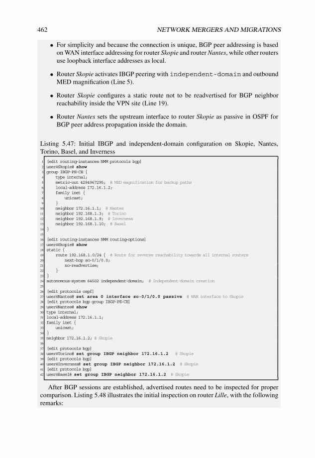
462 NETWORK MERGERS AND MIGRATIONS
• For simplicity and because the connection is unique, BGP peer addressing is basedon WAN interface addressing for router Skopie and router Nantes, while other routersuse loopback interface addresses as local.
• Router Skopie activates IBGP peering with independent-domain and outboundMED magnification (Line 5).
• Router Skopie configures a static route not to be readvertised for BGP neighborreachability inside the VPN site (Line 19).
• Router Nantes sets the upstream interface to router Skopie as passive in OSPF forBGP peer address propagation inside the domain.
Listing 5.47: Initial IBGP and independent-domain configuration on Skopie, Nantes,Torino, Basel, and Inverness
1 [edit routing-instances NMM protocols bgp]2 user@Skopie# show3 group IBGP-PE-CE {4 type internal;5 metric-out 4294967295; # MED magnification for backup paths6 local-address 172.16.1.2;7 family inet {8 unicast;9 }
10 neighbor 172.16.1.1; # Nantes11 neighbor 192.168.1.3; # Torino12 neighbor 192.168.1.9; # Inverness13 neighbor 192.168.1.10; # Basel14 }15
16 [edit routing-instances NMM routing-options]17 user@Skopie# show18 static {19 route 192.168.1.0/24 { # Route for reverse reachability towards all internal routers20 next-hop so-0/1/0.0;21 no-readvertise;22 }23 }24 autonomous-system 64502 independent-domain; # Independent-domain creation25
26 [edit protocols ospf]27 user@Nantes# set area 0 interface so-0/1/0.0 passive # WAN interface to Skopie28 [edit protocols bgp group IBGP-PE-CE]29 user@Nantes# show30 type internal;31 local-address 172.16.1.1;32 family inet {33 unicast;34 }35 neighbor 172.16.1.2; # Skopie36
37 [edit protocols bgp]38 user@Torino# set group IBGP neighbor 172.16.1.2 # Skopie39 [edit protocols bgp]40 user@Inverness# set group IBGP neighbor 172.16.1.2 # Skopie41 [edit protocols bgp]42 user@Basel# set group IBGP neighbor 172.16.1.2 # Skopie
After BGP sessions are established, advertised routes need to be inspected for propercomparison. Listing 5.48 illustrates the initial inspection on router Lille, with the followingremarks:

MPLS LAYER 3 VPN MIGRATIONS 463
• Outbound MED magnification is properly performed while keeping other originalattributes such as LOCAL_PREF and AS_PATH.
• Advertised routes from router Livorno remain as backup paths as a result of MEDcomparison.
• IGP metric (Metric2 ) is 0 for router Livorno as a directly connected PE.
Listing 5.48: IBGP-received routes in Lille from Livorno
1 user@Lille> show route receive-protocol bgp 172.16.100.8 table inet.02
3 inet.0: 29 destinations, 35 routes (29 active, 0 holddown, 0 hidden)4 Prefix Nexthop MED Lclpref AS path5 192.168.10.0/24 172.16.100.8 4294967295 10 64501 I # Maximum MED Out6 192.168.30.0/24 172.16.100.8 4294967295 30 64503 I # Maximum MED Out7 192.168.90.0/24 172.16.100.8 4294967295 90 64509 I # Maximum MED Out8 192.168.100.0/24 172.16.100.8 4294967295 100 64510 I # Maximum MED Out9
10 user@Lille> show route protocol bgp detail |11 match “entr|Protocol next hop|Localpref|metric|AS path”12 192.168.10.0/24 (2 entries, 1 announced)13 Protocol next hop: 192.168.1.114 Age: 2:23:39 Metric: 10 Metric2: 64315 AS path: 64501 I16 Localpref: 1017 Protocol next hop: 172.16.100.818 Inactive reason: Not Best in its group - Route Metric or MED comparison19 Age: 1:51 Metric: 4294967295 Metric2: 0 # Minimal IGP Metric20 AS path: 64501 I21 Localpref: 10 # Same original Localpref22 192.168.30.0/24 (2 entries, 1 announced)23 Protocol next hop: 192.168.1.324 Age: 2:27:19 Metric: 30 Metric2: 64325 AS path: 64503 I26 Localpref: 3027 Protocol next hop: 172.16.100.828 Inactive reason: Not Best in its group - Route Metric or MED comparison29 Age: 35:36 Metric: 4294967295 Metric2: 0 # Minimal IGP Metric30 AS path: 64503 I31 Localpref: 30 # Same original Localpref32 <...>33 192.168.90.0/24 (2 entries, 1 announced)34 Protocol next hop: 192.168.1.935 Age: 2:26:43 Metric: 90 Metric2: 128636 AS path: 64509 I37 Localpref: 9038 Protocol next hop: 172.16.100.839 Inactive reason: Not Best in its group - Route Metric or MED comparison40 Age: 35:36 Metric: 4294967295 Metric2: 0 # Minimal IGP Metric41 AS path: 64509 I42 Localpref: 90 # Same original Localpref43 192.168.100.0/24 (2 entries, 1 announced)44 Protocol next hop: 192.168.1.1045 Age: 2:26:17 Metric: 100 Metric2: 80346 AS path: 64510 I47 Localpref: 10048 Protocol next hop: 172.16.100.849 Inactive reason: Not Best in its group - Route Metric or MED comparison50 Age: 35:36 Metric: 4294967295 Metric2: 0 # Minimal IGP Metric51 AS path: 64510 I52 Localpref: 100 # Same original Localpref
Inspecting a sample route on router Livorno coming over the backbone also reveals howthe ATTRSET is built and detected, as seen in Listing 5.49.

464 NETWORK MERGERS AND MIGRATIONS
Listing 5.49: IBGP-received routes on Lille from Livorno
1 user@Livorno> show route receive-protocol bgp 192.168.1.2 detail |2 table NMM 192.168.10.0/243
4 NMM.inet.0: 7 destinations, 7 routes (7 active, 0 holddown, 0 hidden)5 * 192.168.10.0/24 (1 entry, 1 announced)6 Import Accepted7 Route Distinguisher: 64501:645018 VPN Label: 169 Nexthop: 192.168.1.2
10 Localpref: 10011 AS path: I12 Communities: target:64501:6450113 AttrSet AS: 6450214 MED: 1015 Localpref: 1016 AS path: 64501 I17
18 user@Livorno> show route advertising-protocol bgp 172.16.100.5 detail table NMM192.168.10.0/24
19
20 NMM.inet.0: 7 destinations, 7 routes (7 active, 0 holddown, 0 hidden)21 * 192.168.10.0/24 (1 entry, 1 announced)22 BGP group IBGP-PE-CE type Internal23 Nexthop: Self24 Flags: Nexthop Change25 MED: 429496729526 Localpref: 1027 AS path: [64502] 64501 I
Junos Tip: AS path loop avoidance by means of independent-domains
Another application of the independent-domain feature is to create different AS-path domains for AS loop checking without using any local-as loops knobs.
Reviewing Listing 5.49 again, on Lines 16 and 27 64501 appears as the final customerAS from which this route is originated.
However, 64501 is also the internal AS used in the Service Provider transportbackbone (Line 5), which is configured without any particular allowance for AS loops, asseen in Listing 5.50.
Listing 5.50: Internal AS configuration on Livorno
1 user@Livorno> show bgp neighbor 192.168.1.2 | match “ ˆPeer”2 Peer: 192.168.1.2+55701 AS 64501 Local: 192.168.1.6+179 AS 645013
4 user@Livorno> show configuration routing-options autonomous-system5 64501;6
7 user@Livorno> show configuration routing-instances NMM routing-options8 autonomous-system 64502 independent-domain;
Effectively, the transport Service Provider is not performing any kind of AS path loopchecking in their main instance on this customer’s AS_PATHs, as a consequence of theadditional domain creation triggered by the independent-domain feature. Thosechecks are therefore carried out on a per-independent-domain basis, in this caseindependently in the VRF and in the main routing instance.

MPLS LAYER 3 VPN MIGRATIONS 465
Junos Tip: AS path loop detection per family
The local-as loops knob specifies the maximum number of times that a local AScan appear in AS_PATH attributes from routes received from a BGP peer.
Junos OS considers each AS configured under [edit routing-options] orrelated to the local-as loops knob to be local for loop detection purposes. All theASs across the routing instances are considered to be part of a common AS-path domainor Independent domain, and Junos OS enforces that the loops value is therefore commonto all instances, because AS paths are shared across all of them and loop checking isperformed on a per AS-path domain basis. The main routing table is also considered tobe part of the same AS-path domain, and the same loops value needs to be set if thisfeature is needed.
However, Junos OS also offers the option of configuring a loops count for a particularaddress family for a specific BGP neighbor. In this case, arbitrary values are toleratedand can be distinct from the loops count in the AS-path domain.
From a migration perspective, this functionality requires that loops are granularly setfor each neighbor and AFI/SAFI combination, but relaxes the need to enforce the samevalue across all instances part of the same AS-path domain.
Listing 5.51 shows both configuration commands to set local-as loops on a per-instance basis, requiring the same loops value in all other instances inside the AS-pathdomain (Line 1) and to set the loops count for each family on each BGP neighbor(Line 6).
Listing 5.51: AS loops configuration on Livorno
1 [edit routing-instances NMM protocols bgp] # Local-as loops2 user@Livorno# set group EBGP-PE-CE local-as 64502 loops ?3 Possible completions:4 <loops> Maximum number of times this AS can be in an AS path (1..10)5
6 [edit routing-instances NMM protocols bgp] # Per-family loops7 user@Livorno# set group EBGP-PE-CE neighbor 172.16.100.5 family inet unicast loops ?8 Possible completions:9 <loops> AS-Path loop count (1..10)
A parallel route inspection is performed on the other side of the VPN, namely, by routerNantes, as shown in Listing 5.52, with these results:
• Outbound MED magnification is properly performed while keeping other originalattributes such as LOCAL_PREF and AS_PATH.
• The advertised route from router Skopie remains as a backup path as a result of MEDcomparison. Because the MED is consistent throughout the setup, the same criterionapplies to other internal routers.
• IGP metric (Metric2 ) is 0 for router Skopie as a directly connected PE.
Listing 5.52: IBGP-received routes on router Lille from router Livorno
1 user@Nantes> show route receive-protocol bgp 172.16.1.2 table inet.02
3 inet.0: 36 destinations, 41 routes (36 active, 0 holddown, 0 hidden)
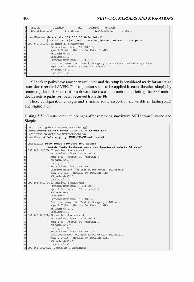
466 NETWORK MERGERS AND MIGRATIONS
4 Prefix Nexthop MED Lclpref AS path5 192.168.50.0/24 172.16.1.2 4294967295 50 64505 I6
7 user@Nantes> show route 192.168.50.0/24 detail8 | match “entr|Protocol next hop|Localpref|metric|AS path”9 192.168.50.0/24 (2 entries, 1 announced)
10 Protocol next hop: 192.168.1.511 Age: 2:55:00 Metric: 50 Metric2: 64312 AS path: 64505 I13 Localpref: 5014 Protocol next hop: 172.16.1.215 Inactive reason: Not Best in its group - Route Metric or MED comparison16 Age: 46:11 Metric: 4294967295 Metric2: 017 AS path: 64505 I18 Localpref: 50
All backup paths have now been evaluated and the setup is considered ready for an activetransition over the L3VPN. This migration step can be applied in each direction simply byremoving the metric-out knob with the maximum metric and letting the IGP metricdecide active paths for routes received from the PE.
These configuration changes and a similar route inspection are visible in Listing 5.53and Figure 5.33.
Listing 5.53: Route selection changes after removing maximum MED from Livorno andSkopie
1 [edit routing-instances NMM protocols bgp]2 user@Livorno# delete group IBGP-PE-CE metric-out3 [edit routing-instances NMM protocols bgp]4 user@Skopie# delete group IBGP-PE-CE metric-out5
6 user@Lille> show route protocol bgp detail7 | match “entr|Protocol next hop|Localpref|metric|AS path”8 192.168.10.0/24 (2 entries, 1 announced)9 Protocol next hop: 172.16.100.8
10 Age: 1:52 Metric: 10 Metric2: 011 AS path: 64501 I12 Localpref: 1013 Protocol next hop: 192.168.1.114 Inactive reason: Not Best in its group - IGP metric15 Age: 3:04:14 Metric: 10 Metric2: 64316 AS path: 64501 I17 Localpref: 1018 192.168.30.0/24 (2 entries, 1 announced)19 Protocol next hop: 172.16.100.820 Age: 1:52 Metric: 30 Metric2: 021 AS path: 64503 I22 Localpref: 3023 Protocol next hop: 192.168.1.324 Inactive reason: Not Best in its group - IGP metric25 Age: 3:07:54 Metric: 30 Metric2: 64326 AS path: 64503 I27 Localpref: 3028 192.168.90.0/24 (2 entries, 1 announced)29 Protocol next hop: 172.16.100.830 Age: 1:52 Metric: 90 Metric2: 031 AS path: 64509 I32 Localpref: 9033 Protocol next hop: 192.168.1.934 Inactive reason: Not Best in its group - IGP metric35 Age: 3:07:18 Metric: 90 Metric2: 128636 AS path: 64509 I37 Localpref: 9038 192.168.100.0/24 (2 entries, 1 announced)

MPLS LAYER 3 VPN MIGRATIONS 467
39 Protocol next hop: 172.16.100.840 Age: 1:52 Metric: 100 Metric2: 041 AS path: 64510 I42 Localpref: 10043 Protocol next hop: 192.168.1.1044 Inactive reason: Not Best in its group - IGP metric45 Age: 3:06:52 Metric: 100 Metric2: 80346 AS path: 64510 I47 Localpref: 10048
49 user@Nantes> show route 192.168.50.0/24 detail |50 match “entr|Protocol next hop|Localpref|metric|AS path”51 192.168.50.0/24 (2 entries, 1 announced)52 Protocol next hop: 172.16.1.253 Age: 1:49 Metric: 50 Metric2: 054 AS path: 64505 I55 Localpref: 5056 Protocol next hop: 192.168.1.557 Inactive reason: Not Best in its group - IGP metric58 Age: 3:08:45 Metric: 50 Metric2: 64359 AS path: 64505 I60 Localpref: 50
Nantes
Skopie
Livorno
Barcelona
Honolulu
192.168.1.1
192.168.1.2
192.168.1.6
192.168.1.7
192.168.1.21
Torino
Lille
192.168.1.9
Inverness
Basel
192.168.1.5
192.168.1.3
192.168.1.10
Area 0.0.0.0
TE extensions
RSVP−TE
Domain "Cyclone"
MPLS BackboneIBGP
PE−CE
BGP 192.168.100.0/24
local−preference 100
MED 100
AS path: 64510BGP 192.168.90.0/24
local−preference 90
MED 90
AS path: 64509
BGP 192.168.30.0/24
local−preference 30
MED 30
As path: 64503 BGP 192.168.10.0/24
local−preference 10
MED 10
AS path: 64501
BGP 192.168.50.0/24
local−preference 50
MED 50
AS path: 64505
EBGP
EBGP
EBGP
EBGP
EBGP
IBGP PE−CE
IBGP Full Mesh internal
AS 64502
OSPF Area 0.0.0.0
MED 0
Active paths
MED 0
Active paths
Figure 5.33: Stage two: make PE-advertised routes preferred.
All active paths in the setup have selected router Skopie and router Livorno as next hops.This can also be seen by checking on router Lille, router Inverness, and router Skopie thatno remaining routes select any backdoor link as next hop, as shown in Listing 5.54.
Listing 5.54: No remaining routes over backdoor links on Lille, Inverness, and Skopie
1 user@Lille> show ospf neighbor2 Address Interface State ID Pri Dead3 172.16.1.25 so-0/1/0.0 Full 192.168.1.1 128 364 172.16.1.29 so-0/1/1.0 Full 192.168.1.3 128 37

468 NETWORK MERGERS AND MIGRATIONS
5
6 user@Lille> show route next-hop 172.16.1.29 table inet.07
8 inet.0: 29 destinations, 35 routes (29 active, 0 holddown, 0 hidden)9
10 user@Lille> show route next-hop 172.16.1.25 table inet.011
12 inet.0: 29 destinations, 35 routes (29 active, 0 holddown, 0 hidden)13
14 user@Nantes> show ospf neighbor15 Address Interface State ID Pri Dead16 172.16.1.97 so-0/2/0.0 Full 192.168.1.3 128 3617 172.16.1.26 so-1/0/0.0 Full 192.168.1.5 128 3218 172.16.1.66 so-1/0/1.0 Full 192.168.1.9 128 3219
20 user@Nantes> show route next-hop 172.16.1.26 table inet.021
22 inet.0: 36 destinations, 41 routes (36 active, 0 holddown, 0 hidden)23
24 user@Torino> show ospf neighbor25 Address Interface State ID Pri Dead26 172.16.1.82 at-1/2/0.1001 Full 192.168.1.10 128 3627 172.16.1.98 so-0/1/0.0 Full 192.168.1.1 128 3728 172.16.1.30 so-1/0/1.0 Full 192.168.1.5 128 3829
30 user@Torino> show route next-hop 172.16.1.30 table inet.031
32 inet.0: 34 destinations, 39 routes (34 active, 0 holddown, 0 hidden)
Because all services are now flowing over the L3VPN, there is no risk when finallydismantling the backdoor links. This is seen in Listing 5.55 and Figure 5.34 after simplydeactivating OSPF on router Lille: all backup paths disappear, but the active routes towardsthe backbone persist.
Listing 5.55: Final OSPF deactivation and decommissioning on Lille
1 [edit]2 user@Lille# deactivate protocols ospf3
4 user@Lille> show route protocol bgp detail |5 match “entr|Protocol next hop|Localpref|metric|AS path”6 192.168.10.0/24 (2 entries, 1 announced)7 Protocol next hop: 172.16.100.88 Age: 21:08 Metric: 10 Metric2: 09 AS path: 64501 I
10 Localpref: 1011 192.168.30.0/24 (2 entries, 1 announced)12 Protocol next hop: 172.16.100.813 Age: 21:08 Metric: 30 Metric2: 014 AS path: 64503 I15 Localpref: 3016 192.168.90.0/24 (2 entries, 1 announced)17 Protocol next hop: 172.16.100.818 Age: 21:08 Metric: 90 Metric2: 019 AS path: 64509 I20 Localpref: 9021 192.168.100.0/24 (2 entries, 1 announced)22 Protocol next hop: 172.16.100.823 Age: 21:08 Metric: 100 Metric2: 024 AS path: 64510 I25 Localpref: 10026
27 user@Nantes> show route 192.168.50.0/24 detail |28 match “entr|Protocol next hop|Localpref|metric|AS path”29 192.168.50.0/24 (1 entry, 1 announced)30 Protocol next hop: 172.16.1.2

MPLS LAYER 3 VPN MIGRATIONS 469
31 Age: 21:38 Metric: 50 Metric2: 032 AS path: 64505 I33 Localpref: 50
Nantes
Skopie
Livorno
Barcelona
Honolulu
192.168.1.1
192.168.1.2
192.168.1.6
192.168.1.7
192.168.1.21
Torino
Lille
192.168.1.9
Inverness
Basel
192.168.1.5
192.168.1.3
192.168.1.10
Area 0.0.0.0
TE extensions
RSVP−TE
Domain "Cyclone"
MPLS BackboneIBGP
PE−CE
BGP 192.168.100.0/24
local−preference 100
MED 100
AS path: 64510BGP 192.168.90.0/24
local−preference 90
MED 90
AS path: 64509
BGP 192.168.30.0/24
local−preference 30
MED 30
As path: 64503 BGP 192.168.10.0/24
local−preference 10
MED 10
AS path: 64501
BGP 192.168.50.0/24
local−preference 50
MED 50
AS path: 64505
EBGP
EBGP
EBGP
EBGP
EBGP
IBGP PE−CE
IBGP Full Mesh internal
AS 64502
OSPF Area 0.0.0.0
MED 0
Active paths
MED 0
Active paths
Figure 5.34: Stage three: dismantle backdoors.
Junos Tip: Integrating standard VPN routes with independent-domains
Consider the final setup from Figure 5.30 with Barcelona injecting in the same VRF,another internal route, namely 192.168.70.0/24.
This route is considered internal to the same L3VPN and is advertised to CEs, equallyeligible as sites from the former domain, as seen in Listing 5.56.
Listing 5.56: Advertisement of internal routes in the same L3VPN on Skopie and Livorno
1 user@Skopie> show route advertising-protocol bgp 172.16.1.12
3 NMM.inet.0: 9 destinations, 9 routes (9 active, 0 holddown, 0 hidden)4 Prefix Nexthop MED Lclpref AS path5 * 192.168.50.0/24 Self 50 50 64505 I6 * 192.168.70.0/24 Self 100 64501 I # Internal route7
8 user@Livorno> show route advertising-protocol bgp 172.16.100.59
10 NMM.inet.0: 8 destinations, 8 routes (8 active, 0 holddown, 0 hidden)11 Prefix Nexthop MED Lclpref AS path12 * 192.168.10.0/24 Self 10 10 64501 I13 * 192.168.30.0/24 Self 30 30 64503 I14 * 192.168.70.0/24 Self 100 64501 I # Internal route15 * 192.168.90.0/24 Self 90 90 64509 I16 * 192.168.100.0/24 Self 100 100 64510 I
The beauty of using the independent-domain feature in this scenario is that iteasily allows integration and expansion of such scenarios while keeping control overroute distribution and attribute manipulation.

470 NETWORK MERGERS AND MIGRATIONS
5.6 Case Study
To put into practice the fundamental concepts related to L3VPN migrations, this case studyfocuses on the different L3VPN interconnection options available when merging domains.Both the inter-AS options discussed in Section 5.2.6 and Carrier Supporting Carrier (CsC) inSection 5.2.7 are implemented in this case study.
The topology being used through this book has been slightly enhanced, as shown inFigure 5.35. Two physical interconnections between router Livorno and router Havana assistin simulating multiple peering options. Connectivity to the CsC provider is available on thefour ASBRs in domain “Monsoon.”
Male
Havana
Frame Relay
CsC PE Nantes
Skopie
LivornoBarcelona
Honolulu
192.168.1.4
192.168.1.20
192.168.1.8
10.10.1.1
192.168.1.2
192.168.1.6
192.168.1.7
192.168.1.21
10.10.1.9
CsC PEInverness
CsC PEBasel
10.10.1.3
10.10.1.10
"Monsoon"
AS64503
"Mistral"
AS64502
"Cyclone"
AS64501
CsC PE Torino
Bilbao
Figure 5.35: Modified topology for Inter-AS case study.
The first section describes the original network. This is followed by a discussion of thetarget network to provide a view of the final scenario. A migration strategy section discussesconsiderations and approaches. Finally, details are given for each migration stage. Only oneVPN, NMM, is considered throughout the case study, with one PE in each domain, but thiscan obviously be generalized.
5.6.1 Original network
The existing scenario is a successful L3VPN service being provided by domain “Cyclone”.The Marketing department of the common service provider “Gale Internet” sees theintegration of domain “Mistral” as a good opportunity to capture more business by extendingVPNs to remote locations in which domain “Mistral” has a presence.
Additional information related to the L3VPN service for VPN NMM has to be considered:
• Domain “Cyclone” provides L3VPN services using many PE routers, of which routerBarcelona is a representative device. At the same time, domain “Mistral” also providesa VPN service, with router Male being a representative PE.

MPLS LAYER 3 VPN MIGRATIONS 471
• VPN NMM is present on router Barcelona. CE attachments for this VPN lie behind thePE routers and are not shown. This full-mesh VPN uses route-target target:64501:64501 on domain “Cyclone” to exchange its prefixes.
• As a representative case of the desire to extend this VPN, PE router Male in domain“Mistral” also built this customer VPN. Because of separate provisioning systemsand operations processes, the short-term agreement between domain “Mistral” anddomain “Cyclone” is to set up independent VPNs at each domain, with domain“Mistral” using route-target target:64502:64502 for this VPN, which isalso called NMM.
• The volume of routing information from PE routers in domain “Mistral” for this VPN isto be controlled by aggregating route blocks on router Havana towards router Livorno.
• Inbound traffic accounting and policing for those aggregates is desired on routerHavana.
5.6.2 Target network
The end goal of the migration is to leverage backbone MPLS transport connectivity froma third party that offers CsC services, as shown in Figure 5.36. PEs in domain “Cyclone”interconnect to PEs in domain “Mistral,” with a combined Option B for domain “Mistral”and Option C for domain “Cyclone,” over the CsC setup in domain “Monsoon.”
PEMale
PEBarcelona
L3VPN ASBR Honolulu
192.168.1.20
192.168.1.7
192.168.1.21
"Monsoon"
AS64503
Carrier
Supporting
Carrier
"Mistral"
AS64502
"Cyclone"
AS64501
Customer prefix
192.168.107.7/32
Customer prefix
192.168.120.0/24
192.168.120.20/32
L−EBG
PL−E
BG
P
L−EBG
P
L−EBG
P
inet−
vpn E
BG
P
inet−vp
n
IBGP
Figure 5.36: Target network migrated with Options B and C over CsC.

472 NETWORK MERGERS AND MIGRATIONS
5.6.3 Migration strategy
Migration planning
For illustration purposes, the unification of the L3VPN service occurs in several stages,covering each of the interconnecting options. There is little time dependency among thestages.
The proposed approach for the migration timeline is shown in Figure 5.37.
• In a first stage, a rapid extension of this service over domain “Mistral” is achievedusing an inter-AS Option A arrangement for all VPNs that have to be shared. To keepthe example focused, only the VPN NMM is considered.
NMM VRFpresent in
domain "Cyclone"
inter−AS option C tointerconnect VPNs using
Carrier Supporting Carrierservices from a third party
1. Option A
2. Option A+Bpreparation
3. Option A+Bactivation
6. Option C−CsCpreparation
7. Option C−CsCactivation
8. Redundant Option C−CsCpreparation
9. Redundant Option C−CsCactivation
4. Option B−CsCpreparation
5. Option B−CsCactivation
Removal of previousconfigurations
Cleanup
Option B over CsC
Option A+B
Option A
Option C over CsC
Redundant Option C over CsC
Done!
Figure 5.37: Approach to interconnect NMM L3VPN between ASs.
• In a second stage, scalable service evolution prompts a change in peering arrangementto Option B while maintaining service independence in each domain. Existing servicerequirements force an Option A+B configuration at the border router Havana forselected prefixes within the L3VPN NMM. This stage completes the preparatory workrequired to keep both Option A and Option B interconnects active, with preferencegiven to the existing Option A interconnect.
• Stage three activates the Option B interconnect and removes the VRF instance onrouter Livorno. For router Havana, however, the NMM VRF has to stay to providean anchoring point for the IP functions of aggregation and accounting, as is discussedlater.
• Transmission cost optimization is introduced in stage four, by retaining the services ofa third-party domain as a CsC. Preparatory work to bring up the session with a lower

MPLS LAYER 3 VPN MIGRATIONS 473
preference ensures that traffic stays on the existing direct interconnect between routerLivorno and router Havana.
• Stage five switches preferences on the Option B interconnect over to the CsC service,redirecting the traffic on the direct Option B interconnect between router Livorno androuter Havana to free up the direct interconnect.
• In a sixth stage, generalization of the connectivity from domain “Mistral” to multiplePEs in domain “Cyclone” is achieved with preparatory work to migrate the Option Bpeering at router Livorno to an Option C interconnect. Reachability to all PEs withindomain “Cyclone” is required for redistribution of MPLS transport labels. To avoida mesh of BGP sessions for L3VPN from all the PE routers in domain “Cyclone”to router Havana, the router Honolulu is established as the ASBR, with a multihopEBGP L3VPN peering session between router Havana and router Honolulu. Businessrequirements force router Havana to remain as the ASBR for domain “Mistral” so thatthis router can continue to hide the internal VPN topology from domain “Mistral” bybeing a relay point for VPN information. Router Havana does so by setting next-hopself on the advertisements for VPN NMM.
• The activation of the Option C interconnect is analyzed in stage seven.
• To showcase possible redundancy issues, the eighth stage establishes an additionalOption C interconnect between router Bilbao and router Honolulu that crosses routerSkopie using the CsC infrastructure.
• As the final stage, stage nine enables this additional session in parallel with the existingOption C interconnects, providing a final setup with Option C connectivity to domain“Cyclone” with the L3VPN peering from router Honolulu to both router Havana androuter Bilbao, which act as ASBRs for domain “Mistral”.
By choosing the right BGP attributes to control route preferences, all transitions inthis case study can be controlled from a single point. This point is chosen to be routerHavana. Table 5.2 provides a summary of the various stages and the preferences given toadvertisements on each of the sessions. The first value represents the LOCAL_PREF to setfor received prefixes; the second value is the MED BGP attribute for advertised prefixes.All the modifications are done on router Havana except for the last column (Opt-C-CsC-Redundant), which is configured on router Bilbao.
5.6.4 Stage one: Inter-AS Option A deployment
As the most straightforward interconnection mechanism, the VRF for VPN NMM isinstantiated on router Havana and router Livorno and a dedicated subinterface connectionis reserved. Figure 5.38 depicts this interconnection stage, which provides a common VPNservice.
The selected location to place the inter-AS Option A interconnection is between routerLivorno and router Havana. Listing 5.57 provides the baseline configuration. VPN NMMleverages one of the multiple subinterfaces that join the various VPNs across the inter-ASbinding. Besides the PE–CE subinterface connection, a specific per-VRF loopback interface
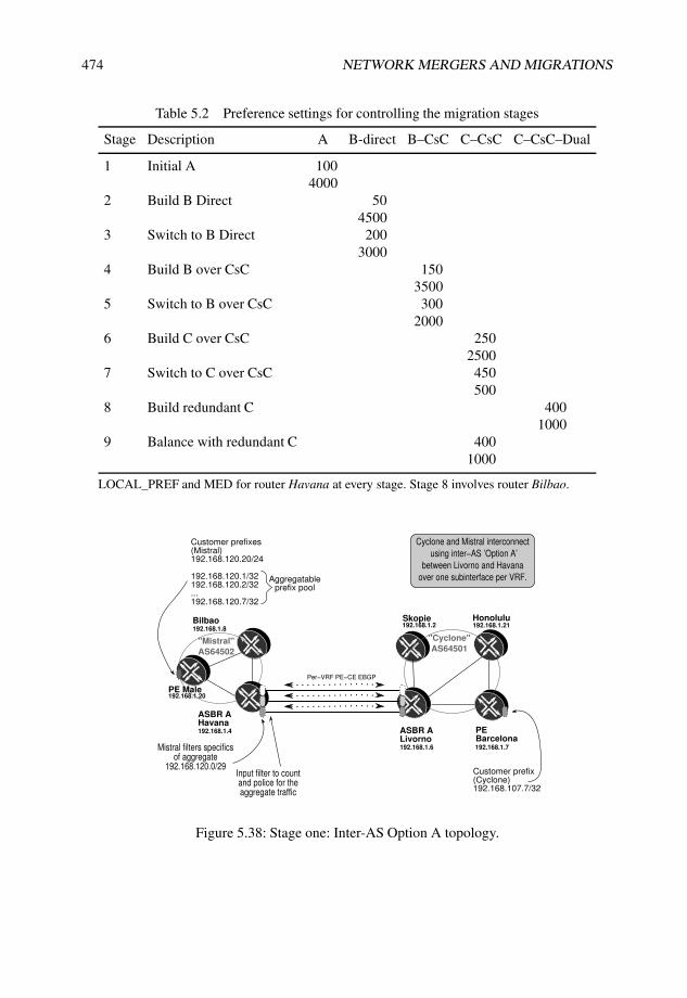
474 NETWORK MERGERS AND MIGRATIONS
Table 5.2 Preference settings for controlling the migration stages
Stage Description A B-direct B–CsC C–CsC C–CsC–Dual
1 Initial A 1004000
2 Build B Direct 504500
3 Switch to B Direct 2003000
4 Build B over CsC 1503500
5 Switch to B over CsC 3002000
6 Build C over CsC 2502500
7 Switch to C over CsC 450500
8 Build redundant C 4001000
9 Balance with redundant C 4001000
LOCAL_PREF and MED for router Havana at every stage. Stage 8 involves router Bilbao.
PE Male
ASBR AHavana
Skopie
ASBR A Livorno
PEBarcelona
Honolulu
192.168.1.4
192.168.1.20
192.168.1.8192.168.1.2
192.168.1.6 192.168.1.7
192.168.1.21
"Mistral"
AS64502
"Cyclone"
AS64501
Customer prefix(Cyclone)192.168.107.7/32
Customer prefixes(Mistral)192.168.120.20/24
192.168.120.1/32192.168.120.2/32...192.168.120.7/32
Aggregatableprefix pool
Per−VRF PE−CE EBGP
Cyclone and Mistral interconnect
using inter−AS ’Option A’
between Livorno and Havana
over one subinterface per VRF.
Mistral filters specificsof aggregate
192.168.120.0/29Input filter to count and police for the aggregate traffic
Bilbao
Figure 5.38: Stage one: Inter-AS Option A topology.

MPLS LAYER 3 VPN MIGRATIONS 475
is added for troubleshooting purposes on Line 4. This loopback address is visible only withinthe domain. Notice that no specific BGP policy is applied to advertise the loopback addressin the interconnection in the BGP configuration block that starts on Line 7. Following defaultBGP policy rules, only BGP routes are advertised to the peer.
Listing 5.57: Baseline configuration for Inter-AS Option A connectivity
1 user@Havana> show configuration routing-instances NMM2 instance-type vrf;3 interface so-1/0/0.100; # PE-CE subinterface for the interconnect4 inactive: interface lo0.104; # VRF loopback used for troubleshooting5 vrf-target target:64502:64502; # Full-mesh RT6 protocols {7 bgp {8 group Cyclone {9 peer-as 64501;
10 neighbor 172.16.250.38; # PE-CE subinterface peering11 }12 }13 }14 user@Livorno> show configuration routing-instances NMM15 instance-type vrf;16 interface so-0/0/1.100; # PE-CE subinterface on interconnect17 inactive: interface lo0.106; # VRF loopback used for troubleshooting18 vrf-target target:64501:64501; # Full-mesh RT19 protocols {20 bgp {21 group Mistral {22 peer-as 64502;23 neighbor 172.16.250.37; # On PE-CE subinterface peering24 }25 }26 }
Listing 5.58 shows successful connectivity within the VPN between prefixes on routerMale and router Barcelona. Notice that the connectivity at Lines 5 and 14 have no MPLSlabel reflecting the plain IP interconnection. The existence of a single MPLS label in thetrace on Line 4 is a consequence of the reduced setup that has no Provider (P) routers and theimplicit-null behavior when signaling transport labels.
Listing 5.58: Inter-AS Option A connectivity verification
1 user@Barcelona-re0> traceroute routing-instance NMM source barcelona-NMM male-NMM2 traceroute to male-NMM (192.168.120.20) from barcelona-NMM, 30 hops max, 40 byte packets3 1 livorno-ge020 (172.16.1.54) 1.112 ms 0.917 ms 0.872 ms4 MPLS Label=305568 CoS=0 TTL=1 S=15 2 havana-so100100 (172.16.250.37) 0.792 ms 0.725 ms 0.702 ms6 3 male-ge4240 (172.16.1.85) 0.801 ms 0.809 ms 0.763 ms7 MPLS Label=299808 CoS=0 TTL=1 S=18 4 male-NMM (192.168.120.20) 0.781 ms 0.828 ms 0.727 ms9
10 user@male-re0> traceroute routing-instance NMM barcelona-NMM source male-NMM11 traceroute to barcelona-NMM (192.168.107.7) from male-NMM, 30 hops max, 40 byte packets12 1 havana-ge1100 (172.16.1.86) 0.744 ms 0.644 ms 0.569 ms13 MPLS Label=301408 CoS=0 TTL=1 S=114 2 livorno-so001100 (172.16.250.38) 0.492 ms 10.015 ms 0.444 ms15 3 barcelona-ge120 (172.16.1.53) 0.830 ms 0.668 ms 0.639 ms16 MPLS Label=302304 CoS=0 TTL=1 S=117 4 barcelona-NMM (192.168.107.7) 0.631 ms 0.598 ms 0.591 ms
Additional considerations in this setup are worth mentioning:
• Concerns about the amount of routing information sourced from sites in domain“Mistral” prompt aggregation of a very specific route block at Havana.

476 NETWORK MERGERS AND MIGRATIONS
• A trust relationship exists between domain “Cyclone” and domain “Mistral” that doesnot require any specific traffic IP processing in domain “Cyclone” at the border routerLivorno. However, inbound traffic from domain “Cyclone” to domain “Mistral” tothose aggregated destinations is considered low priority, and a specific bandwidthpolicing function is to be established inbound at router Havana. It is also desirableto count traffic to these destinations for accounting purposes.
• The impact of default community handling in BGP PE–CE must be considered. InJunos OS, RT communities attached to VPN prefixes are not filtered by default.
Prefix aggregation at the border router
PE router Male receives a large set of prefixes that can be aggregated in simpler blocks.Domain “Cyclone” prefers to keep its control plane scalability under control, and agreeswith the administrators of domain “Mistral” that only aggregates are to be advertised overthe interconnection. Although the aggregation could happen at the PE router Male in thisoversimplified setup, the assumption is that different prefix blocks forming the aggregatablespace are to be sourced by multiple PE routers within domain “Mistral”. Listing 5.59shows how the PE–CE interconnect has an outbound policy (Line 14) to advertise a locallygenerated aggregate (Line 7). Therefore, the ASBR border router Havana, acting as PE,holds aggregate blocks and filters more specific routes (Line 27) using routing policy in itsadvertisements to router Livorno, as shown on Line 49.
Listing 5.59: Filtering more-specific routes in aggregate advertisements
1 user@Havana> show configuration routing-instances NMM2 instance-type vrf;3 interface so-1/0/0.100; # PE-CE subinterface on interconnect4 inactive: interface lo0.104; # VRF loopback used for troubleshooting5 vrf-target target:64502:64502; # Full-mesh RT6 routing-options {7 aggregate {8 route 192.168.120.0/29 discard;9 }
10 }11 protocols {12 bgp {13 group Cyclone {14 export Aggregate;15 peer-as 64501;16 neighbor 172.16.250.38; # On PE-CE subinterface peering17 }18 }19 }20
21 user@Havana> show configuration policy-options policy-statement Aggregate22 term aggregate {23 from protocol aggregate; # Advertise aggregate24 then accept;25 }26 term no-specifics {27 from aggregate-contributor; # Filter out more-specific routes28 then reject;29 }30 user@Havana> show route table NMM 192.168.120/29 terse31
32 NMM.inet.0: 15 destinations, 16 routes (15 active, 0 holddown, 0 hidden)33 + = Active Route, - = Last Active, * = Both34

MPLS LAYER 3 VPN MIGRATIONS 477
35 A Destination P Prf Metric 1 Metric 2 Next hop AS path36 * 192.168.120.0/29 A 130 Discard37 * 192.168.120.1/32 B 170 100 >172.16.1.85 I38 * 192.168.120.2/32 B 170 100 >172.16.1.85 I39 * 192.168.120.3/32 B 170 100 >172.16.1.85 I40 * 192.168.120.4/32 B 170 100 >172.16.1.85 I41 * 192.168.120.5/32 B 170 100 >172.16.1.85 I42 * 192.168.120.6/32 B 170 100 >172.16.1.85 I43 * 192.168.120.7/32 B 170 100 >172.16.1.85 I44
45 user@Havana> show route advertising-protocol bgp 172.16.250.3846
47 NMM.inet.0: 15 destinations, 16 routes (15 active, 0 holddown, 0 hidden)48 Prefix Nexthop MED Lclpref AS path49 * 192.168.120.0/29 Self I # Aggregate50 * 192.168.120.20/32 Self I # Male prefix outside aggregate
IP accounting functions
Listing 5.60 provides the relevant configuration that illustrates how traffic is being accountedand limited for the aggregate. A sample traffic pattern test starting at Line 32 and the resultingstatistics on Line 40 validate this setup. Notice the requirement for input counting andpolicing does not impose any special IP lookup function on egress, so a table-label is notrequired.
Listing 5.60: Counting and filtering traffic towards an aggregate route
1 user@Havana> show configuration firewall2 family inet {3 filter count-and-police {4 term aggregate {5 from {6 destination-address {7 192.168.120.0/29;8 }9 }
10 then {11 policer 1m;12 count aggregate-in;13 }14 }15 term rest {16 then accept;17 }18 }19 }20 policer 1m {21 if-exceeding {22 bandwidth-limit 1m;23 burst-size-limit 10k;24 }25 then discard;26 }27
28 user@Havana> show interfaces filters so-1/0/0.10029 Interface Admin Link Proto Input Filter Output Filter30 so-1/0/0.100 up up inet count-and-police31
32 user@Barcelona-re0> ping routing-instance NMM source barcelona-NMM male-aggr33 rapid count 1000 size 140034 PING male-aggr (192.168.120.1): 56 data bytes35 !!!.!!!.!!!! <...>36 --- male-aggr ping statistics ---37 1000 packets transmitted, 902 packets received, 9% packet loss

478 NETWORK MERGERS AND MIGRATIONS
38 round-trip min/avg/max/stddev = 1.641/1.988/43.545/2.090 ms39
40 user@Havana> show firewall filter count-and-police41 Filter: count-and-police42 Counters:43 Name Bytes Packets44 aggregate-in 1288056 90245 Policers:46 Name Packets47 1m-aggregate 98
Extended communities in the BGP PE–CE
For Option A interconnects, and as a general security measure, it is important to make surethat RT communities are not attached to prefixes coming from CEs. By default, Junos OSgives no special treatment to route policy related to communities, and as such passes themalong unchanged.
Listing 5.61, Line 15, shows the resulting advertisement by router Livorno when nospecific policy is set up outbound, with an extended community attached, as per Line 22.The result is that routers in domain “Mistral” end up with an undesired RT community andact accordingly (Line 43).
Listing 5.61: Advertising IP prefixes with extended communities
1 user@Livorno> show configuration routing-instances2 NMM {3 instance-type vrf;4 interface so-0/0/1.100;5 interface lo0.106;6 vrf-target target:64501:64501;7 protocols {8 bgp {9 group Mistral {
10 export accept-direct; # No special community handling11 peer-as 64502;12 neighbor 172.16.250.37;13 } } } }14 user@Livorno> show route advertising-protocol bgp 172.16.250.37 extensive15 192.168.107.716
17 NMM.inet.0: 7 destinations, 7 routes (7 active, 0 holddown, 0 hidden)18 * 192.168.107.7/32 (1 entry, 1 announced)19 BGP group Mistral type External20 Nexthop: Self21 AS path: [64501] I22 Communities: target:64501:64501 # Prefix Tagged with RT community23
24 user@male-re0> show route table bgp detail | find 192.168.107.725 192.168.1.4:6:192.168.107.7/32 (1 entry, 1 announced)26 *BGP Preference: 170/-10127 Route Distinguisher: 192.168.1.4:628 Next hop type: Indirect29 Next-hop reference count: 930 Source: 192.168.1.431 Next hop type: Router, Next hop index: 81232 Next hop: 172.16.1.86 via ge-4/2/4.0, selected33 Label operation: Push 30145634 Protocol next hop: 192.168.1.435 Push 30145636 Indirect next hop: 8c2c2a0 104858037 State: <Active Int Ext>38 Local AS: 64502 Peer AS: 6450239 Age: 3:19 Metric2: 10

MPLS LAYER 3 VPN MIGRATIONS 479
40 Task: BGP_64502.192.168.1.4+17941 Announcement bits (1): 0-BGP RT Background42 AS path: 64501 I43 Communities: target:64501:64501 target:64502:64502 # Additional RT44 Import Accepted45 VPN Label: 30145646 Localpref: 10047 Router ID: 192.168.1.448 Secondary Tables: NMM.inet.0
A best practice to protect the carrier domain is to filter extended communities usinginbound routing policy, as shown in Listing 5.62. It is also good practice to facilitate thisprotection for the peer by cleaning communities towards the peer. Notice on Line 19 that theupdate contains the RT community, but filtering is effective and the route installed in the VRFtable does not contain it, as shown on Line 21.
Listing 5.62: Protecting Option A interconnect from RT communities received from CE
1 user@Havana> show configuration policy-options2 ...3 policy-statement clean-RT {4 then {5 community delete extended;6 }7 }8 community extended members [ target:*:* origin:*:* ];9
10 user@Havana# set routing-instances NMM protocols bgp group Cyclone import clean-RT11
12 user@Havana> show route receive-protocol bgp 172.16.250.38 detail 192.168.107.7/3213
14 NMM.inet.0: 15 destinations, 16 routes (15 active, 0 holddown, 0 hidden)15 * 192.168.107.7/32 (1 entry, 1 announced)16 Accepted17 Nexthop: 172.16.250.3818 AS path: 64501 I19 Communities: target:64501:64501 # RT community present in regular BGP update20
21 user@Havana> show route table NMM 192.168.107.7/32 detail22
23 NMM.inet.0: 15 destinations, 16 routes (15 active, 0 holddown, 0 hidden)24 192.168.107.7/32 (1 entry, 1 announced)25 *BGP Preference: 170/-10126 Next hop type: Router, Next hop index: 52727 Next-hop reference count: 628 Source: 172.16.250.3829 Next hop: 172.16.250.38 via so-1/0/0.100, selected30 State: <Active Ext>31 Peer AS: 6450132 Age: 15:3233 Task: BGP_64501.172.16.250.38+6463634 Announcement bits (2): 0-KRT 2-BGP RT Background35 AS path: 64501 I36 Accepted37 Localpref: 10038 Router ID: 192.168.106.6
5.6.5 Stage two: Inter-AS Option B deployment
With successful rollout of the Option A interconnect, additional VPNs can be extended overthe interconnect. However, for every new VPN desiring interconnection, a new subinterface

480 NETWORK MERGERS AND MIGRATIONS
has to be allocated, and instantiation of the VRF on both sides of the interconnection needsto occur.
Provisioning quickly becomes a burden, and a decision is made to adopt a more scalableapproach, focusing only on the local interconnect first. The alternative chosen is Option B,as shown in Figure 5.39, which sets up an MPLS interconnect on a connection that has nosubinterfaces and removes the requirement of instantiating VRFs at the borders.
Skopie Honolulu192.168.1.8
192.168.1.2 192.168.1.21
"Mistral"
AS64502
"Cyclone"
AS64501
MP−EBGP
Inter−AS option B
Per−VRF PE−CE EBGP
Cyclone and Mistral interconnect
using additional inter−AS ’Option B’
between Livorno and Havana
over a single MPLS link.
Bilbao
ASBR BHavana192.168.1.4
ASBR B Livorno192.168.1.6
PEBarcelona192.168.1.7
PE Male192.168.1.20
Figure 5.39: Stage two: Inter-AS Option B topology.
Migration to this type of interconnection must be designed with some considerations inmind:
• A smooth transition calls for parallel Option A and Option B sessions to validateconnectivity at the control plane first, before switching service to the new interconnect.To ease migration control, decisions are centralized at router Havana by setting ofthe LOCAL_PREF BGP attribute for inbound updates and the MED BGP attribute toinfluence outbound updates, as per Table 5.2 on Page 474.
• Shared VPNs have to agree on the RT community to use. Of the approaches describedin Section 5.2.6, mapping of RT is implemented. Using policy language in theoutbound direction, an additional RT is added at the ASBR to match the AS of thepeer. To avoid adding the same community multiple times, this addition is performedonly if the community is not already present.
• The aggregation point on router Havana for L3VPN NMM filters more specific routesas contributing members of the aggregate. In a regular Option B scenario, each route isa separate NLRI formed from the RD and a prefix and that populates bgp.l3vpn.0. Inthis interconnect option, the concept of a contributing route does not exist; therefore,more specific routes bear no relation to the aggregate.

MPLS LAYER 3 VPN MIGRATIONS 481
• The aggregation point on router Havana for L3VPN NMM advertises a VPN label fora route that represents a different next hop. Each more specific route probably has adifferent VPN label, so using the VPN label of the aggregate for forwarding mightsend traffic to the wrong more specific prefix. It is necessary to enable an Option A+Bbehavior, at least for the aggregate prefix.
• L3VPN NMM has a requirement for inbound accounting on router Havana. This canbe implemented by leveraging the same Option A+B configuration. The VPN label forthe aggregate route maps to an IP lookup at the VRF, allowing for a forwarding tablefilter to be applied.
Bringup of depreferred Option B
To ease incremental transition, the current interface interconnecting router Havana and routerLivorno that has one subinterface for each VRF is maintained, and an additional link is set upto establish pure MPLS connectivity. The extended configuration illustrated in Listing 5.63assumes that a new interface has been provisioned with MPLS capabilities and establishesa new BGP peering group for family inet-vpn named EBGP-Cyclone-vpn-Livorno-WAN.Provisioning configuration includes forcing the BGP attributes to deprefer any updates inboth directions over this session as shown on Lines 3 and 8.
Listing 5.63: New Option B inet-vpn session with depreference
1 user@Havana> show configuration protocols bgp group EBGP-Cyclone-vpn-Livorno-WAN2 type external;3 metric-out 4500; # Depreference outbound updates4 local-address 172.16.100.1;5 family inet-vpn {6 unicast;7 }8 import LP50; # Depreference inbound updates9 peer-as 64501;
10 neighbor 172.16.100.8;11
12 user@Livorno> show configuration protocols bgp group EBGP-Mistral-vpn-Havana-WAN13 type external;14 local-address 172.16.100.8;15 family inet-vpn {16 unicast;17 }18 peer-as 64502;19 neighbor 172.16.100.1;
Because this is the first EBGP group for inet-vpn prefixes, a switch in path selection modetriggers a restart on all inet-vpn sessions. Section 1.2.2 provides more information about thisbehavior.
Listing 5.64 shows the resulting information being exchanged over the inet-vpn sessionas received on each end. Notice that prefixes advertised by router Livorno have a diminishedlocal preference value of 50 and that router Livorno receives advertisements with a highermetric value of 4500 to ensure that prefixes are not preferred.
Comparing this output with the Option A interconnect in Listing 5.59, Line 45, the morespecific prefixes are now advertised along with the aggregate (Line 25 to Line 37).

482 NETWORK MERGERS AND MIGRATIONS
Listing 5.64: NLRI exchange after bringup of Option B
1 user@Havana> show route table bgp source-gateway 172.16.100.82
3 bgp.l3vpn.0: 15 destinations, 15 routes (15 active, 0 holddown, 0 hidden)4 + = Active Route, - = Last Active, * = Both5
6 192.168.1.6:4:172.16.250.36/307 *[BGP/170] 00:04:16, localpref 508 AS path: 64501 I9 > to 172.16.100.8 via fe-0/3/0.0, Push 305056
10 192.168.1.7:14:192.168.107.7/3211 *[BGP/170] 00:04:16, localpref 5012 AS path: 64501 I13 > to 172.16.100.8 via fe-0/3/0.0, Push 30560014
15 user@Livorno> show route receive-protocol bgp 172.16.100.1 table bgp16
17 bgp.l3vpn.0: 16 destinations, 16 routes (16 active, 0 holddown, 0 hidden)18 Prefix Nexthop MED Lclpref AS path19 192.168.1.4:6:172.16.250.36/3020 * 172.16.100.1 4500 64502 I21 192.168.1.4:6:192.168.104.4/3222 * 172.16.100.1 4500 64502 I23 192.168.1.4:6:192.168.120.0/2924 * 172.16.100.1 4500 64502 I25 192.168.1.20:10:192.168.120.1/3226 * 172.16.100.1 4500 64502 I27 192.168.1.20:10:192.168.120.2/3228 * 172.16.100.1 4500 64502 I29 192.168.1.20:10:192.168.120.3/3230 * 172.16.100.1 4500 64502 I31 192.168.1.20:10:192.168.120.4/3232 * 172.16.100.1 4500 64502 I33 192.168.1.20:10:192.168.120.5/3234 * 172.16.100.1 4500 64502 I35 192.168.1.20:10:192.168.120.6/3236 * 172.16.100.1 4500 64502 I37 192.168.1.20:10:192.168.120.7/3238 * 172.16.100.1 4500 64502 I39 192.168.1.20:10:192.168.120.20/3240 * 172.16.100.1 4500 64502 I
RT community mapping
No information from the other domain is populating the local VRF despite the informationbeing exchanged properly over the Option B interconnect because of a mismatch in theRT communities. Listing 5.65 shows the mapping policy that is implemented (Line 2 andLine 15) and later applied (Line 28 and Line 33) to the configuration, as well as a sampleprefix with both communities on Line 46 and Line 56.
Listing 5.65: RT mapping at the borders
1 [edit]2 user@Havana# show policy-options policy-statement map-RT-to-Cyclone3 term NMM-checkBoth {4 from community CycloneAndMistral-NMM;5 then next policy;6 }7 term NMM-addCyclone {8 from community Mistral-NMM;9 then {
10 community add Cyclone-NMM;11 }

MPLS LAYER 3 VPN MIGRATIONS 483
12 }13
14 [edit]15 user@Livorno# show policy-options policy-statement map-RT-to-Mistral16 term NMM-checkBoth {17 from community CycloneAndMistral-NMM;18 then next policy;19 }20 term NMM-addMistral {21 from community Cyclone-NMM;22 then {23 community add Mistral-NMM;24 }25 }26
27 [edit protocols bgp]28 user@Havana# show group EBGP-Cyclone-vpn-Livorno-WAN | compare rollback 129 [edit protocols bgp group EBGP-Cyclone-vpn-Livorno-WAN]30 + export map-RT-to-Cyclone;31
32 [edit protocols bgp]33 user@Livorno# show group EBGP-Mistral-vpn-Havana-WAN | compare rollback 134 [edit protocols bgp group EBGP-Mistral-vpn-Havana-WAN]35 + export map-RT-to-Mistral;36
37 user@Havana> show route advertising-protocol bgp 172.16.100.8 detail | find 12038 * 192.168.1.4:6:192.168.120.0/29 (1 entry, 1 announced)39 BGP group EBGP-Cyclone-vpn-Livorno-WAN type Externa40 Route Distinguisher: 192.168.1.4:641 VPN Label: 30161642 Nexthop: Self43 Flags: Nexthop Change44 MED: 450045 AS path: [64502] I (LocalAgg)46 Communities: target:64501:64501 target:64502:6450247 <...>48
49 user@Havana> show route receive-protocol bgp 172.16.100.8 detail table bgp | find 10750 * 192.168.1.7:14:192.168.107.7/32 (1 entry, 1 announced)51 Import Accepted52 Route Distinguisher: 192.168.1.7:1453 VPN Label: 30560054 Nexthop: 172.16.100.855 AS path: 64501 I56 Communities: target:64501:64501 target:64502:64502
The result of activating this configuration is shown in Listing 5.66 for a prefix from routerBarcelona present on router Havana with two feasible paths, one for each interconnectiontype. Notice on Line 9 that the inactive path has a lower local preference setting.
Listing 5.66: Sample population of NMM VRF with depreferred Option B information
1 user@Havana> show route table NMM 192.168.107.72
3 NMM.inet.0: 13 destinations, 15 routes (13 active, 0 holddown, 0 hidden)4 + = Active Route, - = Last Active, * = Both5
6 192.168.107.7/32 *[BGP/170] 01:46:20, localpref 1007 AS path: 64501 I8 > to 172.16.250.38 via so-1/0/0.100 # Over PE-CE option A9 [BGP/170] 00:00:30, localpref 50
10 AS path: 64501 I11 > to 172.16.100.8 via fe-0/3/0.0, Push 305600 # Over MPLS interconnect

484 NETWORK MERGERS AND MIGRATIONS
Filtering more-specific routes for an aggregate
The resulting advertised information shown in Listing 5.65, Line 15 on Page 482 for routerLivorno still includes the aggregate routes. Filtering for these is done in the Option Ainterconnect at the routing-instance level (Listing 5.59, Line 14 on Page 476), and a similarpolicy has to be applied to the advertisement over the VPN connection. However, in theOption B, the aggregate route becomes another route, decoupled from the contributing ones.It is not feasible to use the aggregate-contributor condition (Listing 5.59 Line 27).
The configuration shown in Listing 5.67 allows matching on the route-filter to filter morespecific prefixes than the aggregate at the ASBR Option B interconnect. As the RD part isignored in the match, an additional RT community match constrains this filtering to the NMMVRF. The result of this configuration change is shown on Line 18, which reports that filteringworks correctly advertising only the aggregate and a route outside of the aggregate block(Line 26).
Listing 5.67: Using route-filter to filter VPN aggregate contributors
1 user@Havana> show configuration policy-options policy-statement block-specifics2 term members {3 from {4 community Mistral-NMM;5 route-filter 192.168.120.0/29 longer;6 }7 then reject;8 }9
10 user@Havana> show configuration policy-options community Mistral-NMM11 members target:64502:64502;12
13 user@Havana> show configuration | compare rollback 114 [edit protocols bgp group EBGP-Cyclone-vpn-Livorno-WAN]15 - export map-RT-to-Cyclone;16 + export [ map-RT-to-Cyclone block-specifics ];17
18 user@Havana> show route advertising-protocol bgp 172.16.100.819
20 bgp.l3vpn.0: 14 destinations, 14 routes (14 active, 0 holddown, 0 hidden)21 Prefix Nexthop MED Lclpref AS path22 192.168.1.4:6:172.16.250.36/3023 * Self 4500 I24 192.168.1.4:6:192.168.120.0/2925 * Self 4500 I26 192.168.1.20:10:192.168.120.20/3227 * Self 4500 I
Forwarding for aggregated prefixes in transit
An aggregate route within a VPN represents multiple final destinations, namely each of thecontributing routes. The contributing routes may be sourced from different VRFs in differentPEs with distinct VPN labels. If forwarding is performed by MPLS, information about themore specific destination is hidden behind the aggregate prefix in which a single VPN labelis associated.
The IP lookup function supports checking for the more-specific route, thus providingoptimal cost forwarding. Therefore, VRF NMM enables local table-label allocation for theaggregate. Only the aggregate route requires this IP lookup, so a selective policy as shown inListing 5.68 is configured, with the following components:

MPLS LAYER 3 VPN MIGRATIONS 485
• vrf-table-label is enabled for the entire VRF. This automatically enablesadvertising of the table-label in all outgoing announcements with this RT, both localand transit.
• label allocation policy on Line 12 as defined on Line 27 and Line 36 reversesthe default for all prefixes except the aggregate.
• label substitution policy on Line 13 does not perform any substitution fortransit labels, as per the policy definition on Line 44. This ensures that the combinedfunctionality for Option A+B is enabled only for the aggregate route. Other prefixesare processed in a standard Option B fashion.
Listing 5.68: Advertising a table-label for the aggregate route
1 user@Havana> show configuration routing-instances NMM2 instance-type vrf;3 interface so-1/0/0.100;4 interface lo0.104;5 vrf-target target:64502:64502;6 vrf-table-label; # Allocate a table-label7 routing-options {8 aggregate {9 route 192.168.120.0/29 discard;
10 }11 label {12 allocation [ aggregate-allocation default-nexthop ]; # Only the aggregate13 substitution none; # Keep transit routes on pure MPLS14 }15 }16 protocols {17 bgp {18 group Cyclone {19 import clean-RT;20 export Aggregate; # Advertisement on Option A; does not affect Option B session21 peer-as 64501;22 neighbor 172.16.250.38;23 }24 }25 }26
27 user@Havana> show configuration policy-options policy-statement aggregate-allocation28 term aggregate {29 from protocol aggregate;30 then {31 label-allocation per-table;32 accept;33 }34 }35
36 user@Havana> show configuration policy-options policy-statement default-nexthop37 term default {38 then {39 label-allocation per-nexthop;40 accept;41 }42 }43
44 user@Havana> show configuration policy-options policy-statement none45 then reject;
The introduction of the vrf-table-label command changes VPN label advertise-ment for all prefixes so that an IP lookup function is performed. The above changes yield an

486 NETWORK MERGERS AND MIGRATIONS
IP function only for a restricted set of prefixes, namely the locally originated aggregate. Thisaction can be verified by looking at the advertising information in Listing 5.69 for both theIBGP (Line 1) and EBGP sessions (Line 15).
Notice that the prefix of router Barcelona is advertised twice to router Male. The RD partconstructed with the loopback address of the router shows that one of the copies is locallyoriginated on router Havana as part of the Option A interconnect (Line 6), while the otherprefix is learned over the Option B session (Line 12).
Listing 5.69: Directing the aggregate only to transit IP function
1 user@Havana> show route advertising-protocol bgp 192.168.1.20 detail | match “\*|VPN”2
3 bgp.l3vpn.0: 14 destinations, 14 routes (14 active, 0 holddown, 0 hidden)4 * 192.168.1.4:6:172.16.250.36/30 (1 entry, 1 announced)5 VPN Label: 3014726 * 192.168.1.4:6:192.168.107.7/32 (1 entry, 1 announced)7 VPN Label: 3015048 * 192.168.1.4:6:192.168.120.0/29 (1 entry, 1 announced)9 VPN Label: 16 # Table-Label. IP lookup in force
10 * 192.168.1.6:4:172.16.250.36/30 (1 entry, 1 announced)11 VPN Label: 30152012 * 192.168.1.7:14:192.168.107.7/32 (1 entry, 1 announced)13 VPN Label: 30155214
15 user@Havana> show route advertising-protocol bgp 172.16.100.8 detail16
17 bgp.l3vpn.0: 14 destinations, 14 routes (14 active, 0 holddown, 0 hidden)18 * 192.168.1.4:6:172.16.250.36/30 (1 entry, 1 announced)19 BGP group EBGP-Cyclone-vpn-Livorno-WAN type Externa20 Route Distinguisher: 192.168.1.4:621 VPN Label: 30147222 Nexthop: Self23 Flags: Nexthop Change24 MED: 450025 AS path: [64502] I26 Communities: target:64501:64501 target:64502:6450227
28 * 192.168.1.4:6:192.168.120.0/29 (1 entry, 1 announced)29 BGP group EBGP-Cyclone-vpn-Livorno-WAN type Externa30 Route Distinguisher: 192.168.1.4:631 VPN Label: 16 # Table-Label. IP lookup in force32 Nexthop: Self33 Flags: Nexthop Change34 MED: 450035 AS path: [64502] I (LocalAgg)36 Communities: target:64501:64501 target:64502:6450237
38 * 192.168.1.20:10:192.168.120.20/32 (1 entry, 1 announced)39 BGP group EBGP-Cyclone-vpn-Livorno-WAN type Externa40 Route Distinguisher: 192.168.1.20:1041 VPN Label: 30158442 Nexthop: Self43 Flags: Nexthop Change44 MED: 450045 AS path: [64502] I46 Communities: target:64501:64501 target:64502:6450247
48 user@Havana> show route table mpls label 1649
50 mpls.0: 11 destinations, 11 routes (11 active, 0 holddown, 0 hidden)51 + = Active Route, - = Last Active, * = Both52
53 16 *[VPN/0] 17:33:1354 to table NMM.inet.0, Pop

MPLS LAYER 3 VPN MIGRATIONS 487
Allowing for IP accounting functions in Option B
The accounting functions already present on the Option A PE–CE subinterface have to bemigrated to the new interconnect. IP lookup functions are available on a per-VRF basis, so thepre-existing input filter has to be mapped to the VRF as an input forwarding table filter. Withthe previous label substitution procedures, only the aggregate requires an IP lookup function,and the policing can be done for the VRF as a whole. Listing 5.70 shows the additionalconfiguration for this simple scenario. The original interface filter (Line 3) is duplicated as atable filter (Line 4) and is applied to the NMM VRF forwarding table on Line 24.
Listing 5.70: Moving filtering from interface to VRF
1 user@Havana> show configuration | compare rollback 12 [edit firewall family inet]3 filter count-and-police { ... } # Interface filter on the PE-CE interface4 + filter count-and-police-table { # Table-filter definition for the VRF5 + term aggregate {6 + from {7 + destination-address {8 + 192.168.120.0/29;9 + }
10 + }11 + then {12 + policer 1m;13 + count aggregate-in;14 + }15 + }16 + term rest {17 + then accept;18 + }19 + }20 [edit routing-instances NMM]21 + forwarding-options {22 + family inet {23 + filter {24 + input count-and-police-table; # Apply table-filter25 + }26 + }27 + }
A forwarding test with the newly implemented filter is shown in Listing 5.71, which showsthat all the traffic currently being carried by the Option A interconnect is passing through thesubinterface filter. The end result is a two level counting/policing stage, triggering counting attwo places, namely the PE–CE interface at the Option A interconnect (Line 12) and the inputfilter before lookup in the NMM VRF table (Line 20). Cleaning up the Option A configurationremoves the subinterface filter.
Listing 5.71: Forwarding test with both filters in place
1 user@Barcelona-re0> ping routing-instance NMM source barcelona-NMM male-aggr2 rapid count 1000 size 14003 PING male-aggr (192.168.120.1): 1400 data bytes4 !!!!!!!!!.!!!!!!!!5 <...>6 --- male-aggr ping statistics ---7 1000 packets transmitted, 902 packets received, 9% packet loss8 round-trip min/avg/max/stddev = 1.637/1.962/42.015/1.973 ms9
10 user@Havana> show firewall11
12 Filter: count-and-police # PE-CE input interface filter13 Counters:

488 NETWORK MERGERS AND MIGRATIONS
14 Name Bytes Packets15 aggregate-in 1288056 90216 Policers:17 Name Packets18 1m-aggregate 9819
20 Filter: count-and-police-table # NMM VRF input table filter21 Counters:22 Name Bytes Packets23 aggregate-in 1288056 90224 Policers:25 Name Packets26 1m-aggregate 0
Junos Tip: Traffic affected by a forwarding table filter
A forwarding table filter is processed for every packet that has to be looked up, regardlessof the incoming interface. In a general case, the simple filter used in this case study wouldneed to be tailored to ensure that the directionality of traffic is taken into account, by addingan input interface match condition.
In this particular scenario, given that only the aggregate prefix is being advertised witha table-label, no other traffic is expected to hit the filter after the transition from Option Ahas concluded, so the input interface match condition is not used.
More detail about the possible placements of a firewall filter is given in Section 1.3.2 onPage 19.
5.6.6 Stage three: Inter-AS Option B activationThe relevant configuration is in place at both ASBR router Livorno and router Havana, albeitwith depreferred routes. It is time to confirm at the control plane that everything is learnedas expected. Only when routing information learned over the Option A interconnect can bemade less interesting is it time to switch over the forwarding to the Option B interconnect.
Verification of initial state
Three prefixes are relevant at this point: the aggregate block 192.168.120.0/29 in domain“Mistral” and the two prefixes representing the end customers at each side, 192.168.120.20/32for router Male and 192.168.107.7/32 for router Barcelona. The next-hop interface for eachof the prefixes is outlined in Listing 5.72 from both sides of the inter-AS connection on routerHavana and router Livorno.
Besides the contributing routes, router Havana shows the additional route from the OptionB prefix belonging to router Barcelona as less preferred (local preference 50) on Line 10, witha lower metric value (MED 4500) for prefixes from domain “Mistral” as learned by routerLivorno on Line 38 and Line 44. The aggregate prefix 192.168.120.0/29 received on routerLivorno correctly shows a table-label on Line 40.
Listing 5.72: Prefix state prior to Option B activation
1
2 user@Havana> show route table NMM3
4 NMM.inet.0: 12 destinations, 14 routes (12 active, 0 holddown, 0 hidden)5 + = Active Route, - = Last Active, * = Both6

MPLS LAYER 3 VPN MIGRATIONS 489
7 192.168.107.7/32 *[BGP/170] 03:57:54, localpref 1008 AS path: 64501 I9 > to 172.16.250.38 via so-1/0/0.100 # Option A preferred
10 [BGP/170] 01:34:56, localpref 5011 AS path: 64501 I12 > to 172.16.100.8 via fe-0/3/0.0, Push 30560013 192.168.120.0/29 *[Aggregate/130] 1d 04:03:1914 Discard15 192.168.120.1/32 *[BGP/170] 00:00:12, localpref 100, from 192.168.1.2016 AS path: I17 > to 172.16.1.85 via ge-1/1/0.0, Push 29980818 <...>19 192.168.120.7/32 *[BGP/170] 00:00:12, localpref 100, from 192.168.1.2020 AS path: I21 > to 172.16.1.85 via ge-1/1/0.0, Push 29982422 192.168.120.20/32 *[BGP/170] 00:00:12, localpref 100, from 192.168.1.2023 AS path: I24 > to 172.16.1.85 via ge-1/1/0.0, Push 29980825
26 user@Livorno> show route table NMM27
28 NMM.inet.0: 5 destinations, 8 routes (5 active, 0 holddown, 0 hidden)29 + = Active Route, - = Last Active, * = Both30
31 <...>32 192.168.107.7/32 *[BGP/170] 03:28:05, localpref 100, from 192.168.1.733 AS path: I34 > to 172.16.1.53 via ge-0/2/0.0, label-switched-path Livorno-to-Barcelona35 192.168.120.0/29 *[BGP/170] 02:26:51, MED 4000, localpref 100 # Better MED for option A36 AS path: 64502 I37 > to 172.16.250.37 via so-0/0/1.10038 [BGP/170] 01:36:14, MED 4500, localpref 100 # Worse MED for option B39 AS path: 64502 I40 > to 172.16.100.1 via fe-0/3/0.0, Push 1641 192.168.120.20/32 *[BGP/170] 02:26:51, MED 4000, localpref 100 # Better MED for option A42 AS path: 64502 I43 > to 172.16.250.37 via so-0/0/1.10044 [BGP/170] 02:13:22, MED 4500, localpref 100 # Worse MED for option B45 AS path: 64502 I46 > to 172.16.100.1 via fe-0/3/0.0, Push 301584
Activation of Option B
Listing 5.73 modifies preferences as instructed in Table 5.3. The better LOCAL_PREF andMED BGP settings on the direct Option B session are changed as shown on Line 1, with thenew table outputs showing a reverse situation from that in the premigration stage, with best-path selection now preferring the inter-AS Option B routes (Line 16, Line 57, and Line 63).
Table 5.3 Change in preference settings to switch to option B
Stage Description A B–direct B–CsC C–CsC C–CsC–Dual
1 Initial A 1004000
2 Build B Direct 504500
3 Switch to B Direct 2003000

490 NETWORK MERGERS AND MIGRATIONS
Listing 5.73: Prefix state after Option B activation
1 user@Havana> show configuration | compare rollback 12 [edit protocols bgp group EBGP-Cyclone-vpn-Livorno-WAN] # Inter-AS option B interconnection3 - metric-out 4500;4 + metric-out 3000; # Better MED5 - import LP50;6 + import LP200; # Better LOCAL_PREF7
8 user@Havana> show route table NMM9
10 NMM.inet.0: 12 destinations, 14 routes (12 active, 0 holddown, 0 hidden)11 + = Active Route, - = Last Active, * = Both12
13 <...>14 192.168.107.7/32 *[BGP/170] 00:02:06, localpref 20015 AS path: 64501 I16 > to 172.16.100.8 via fe-0/3/0.0, Push 305600 # Option B preferred17 [BGP/170] 04:25:54, localpref 10018 AS path: 64501 I19 > to 172.16.250.38 via so-1/0/0.10020 192.168.120.0/29 *[Aggregate/130] 1d 04:49:3621 Discard22 192.168.120.1/32 *[BGP/170] 00:02:06, localpref 100, from 192.168.1.2023 AS path: I24 > to 172.16.1.85 via ge-1/1/0.0, Push 29980825 192.168.120.2/32 *[BGP/170] 00:02:06, localpref 100, from 192.168.1.2026 AS path: I27 > to 172.16.1.85 via ge-1/1/0.0, Push 29982428 192.168.120.3/32 *[BGP/170] 00:02:06, localpref 100, from 192.168.1.2029 AS path: I30 > to 172.16.1.85 via ge-1/1/0.0, Push 29982431 192.168.120.4/32 *[BGP/170] 00:02:06, localpref 100, from 192.168.1.2032 AS path: I33 > to 172.16.1.85 via ge-1/1/0.0, Push 29982434 192.168.120.5/32 *[BGP/170] 00:02:06, localpref 100, from 192.168.1.2035 AS path: I36 > to 172.16.1.85 via ge-1/1/0.0, Push 29982437 192.168.120.6/32 *[BGP/170] 00:02:06, localpref 100, from 192.168.1.2038 AS path: I39 > to 172.16.1.85 via ge-1/1/0.0, Push 29982440 192.168.120.7/32 *[BGP/170] 00:02:06, localpref 100, from 192.168.1.2041 AS path: I42 > to 172.16.1.85 via ge-1/1/0.0, Push 29982443 192.168.120.20/32 *[BGP/170] 00:02:06, localpref 100, from 192.168.1.2044 AS path: I45 > to 172.16.1.85 via ge-1/1/0.0, Push 29980846
47 user@Livorno> show route table NMM48
49 NMM.inet.0: 5 destinations, 8 routes (5 active, 0 holddown, 0 hidden)50 + = Active Route, - = Last Active, * = Both51
52 192.168.107.7/32 *[BGP/170] 02:41:17, localpref 100, from 192.168.1.753 AS path: I54 > to 172.16.1.53 via ge-0/2/0.0, label-switched-path Livorno-to-Barcelona55 192.168.120.0/29 *[BGP/170] 00:03:19, MED 3000, localpref 10056 AS path: 64502 I57 > to 172.16.100.1 via fe-0/3/0.0, Push 16 # Table-Label IP lookup58 [BGP/170] 02:54:46, MED 4000, localpref 10059 AS path: 64502 I60 > to 172.16.250.37 via so-0/0/1.10061 192.168.120.20/32 *[BGP/170] 00:03:19, MED 3000, localpref 10062 AS path: 64502 I63 > to 172.16.100.1 via fe-0/3/0.0, Push 301584 # Option B preferred64 [BGP/170] 02:54:46, MED 4000, localpref 10065 AS path: 64502 I66 > to 172.16.250.37 via so-0/0/1.100

MPLS LAYER 3 VPN MIGRATIONS 491
Both traceroute and forwarding through the firewall filter confirm that traffic is taking theOption B interconnect, as illustrated in Listing 5.74. No traffic is counted on the subinterfacefilter on Line 18 and an end-to-end path with MPLS labels is present for every hop (onLine 31) as well as the reverse path (on Line 41). Notice that only one label is present atevery hop because Option B is stitching labels at the VPN level.
Listing 5.74: Connectivity verification after transition to Option B
1
2 user@Barcelona-re0> ping routing-instance NMM source barcelona-NMM male-aggr3 rapid count 1000 size 14004 PING male-aggr (192.168.120.1): 1400 data bytes5 !!!!!!!!!.!!!!!!!!!.!6 <...>7 --- male-aggr ping statistics ---8 1000 packets transmitted, 903 packets received, 9% packet loss9 round-trip min/avg/max/stddev = 2.015/2.433/35.796/2.328 ms
10
11 user@Havana> show firewall12
13 Filter: __default_bpdu_filter__14
15 Filter: count-and-police16 Counters:17 Name Bytes Packets18 aggregate-in 0 019 Policers:20 Name Packets21 1m-aggregate 022
23 Filter: count-and-police-table24 Counters:25 Name Bytes Packets26 aggregate-in 1288056 90227 Policers:28 Name Packets29 1m-aggregate 9830
31 user@Barcelona-re0> traceroute routing-instance NMM source barcelona-NMM male-NMM32 traceroute to male-NMM (192.168.120.20) from barcelona-NMM, 30 hops max, 40 byte packets33 1 livorno-ge020 (172.16.1.54) 1.509 ms 1.261 ms 1.218 ms34 MPLS Label=305696 CoS=0 TTL=1 S=135 2 havana-fe0300 (172.16.100.1) 1.353 ms 1.224 ms 1.165 ms36 MPLS Label=301584 CoS=0 TTL=1 S=137 3 male-ge4240 (172.16.1.85) 0.854 ms 0.849 ms 0.816 ms38 MPLS Label=299808 CoS=0 TTL=1 S=139 4 male-NMM (192.168.120.20) 0.799 ms 0.777 ms 0.763 ms40
41 user@male-re0> traceroute routing-instance NMM source male-NMM barcelona-NMM42 traceroute to barcelona-NMM (192.168.107.7) from male-NMM, 30 hops max, 40 byte packets43 1 havana-ge1100 (172.16.1.86) 1.438 ms 1.129 ms 1.095 ms44 MPLS Label=301552 CoS=0 TTL=1 S=145 2 livorno-fe030 (172.16.100.8) 1.228 ms 1.080 ms 1.088 ms46 MPLS Label=305600 CoS=0 TTL=1 S=147 3 barcelona-ge120 (172.16.1.53) 0.726 ms 0.690 ms 0.687 ms48 MPLS Label=302304 CoS=0 TTL=1 S=149 4 barcelona-NMM (192.168.107.7) 0.670 ms 0.643 ms 0.659 ms50
Decommissioning of Option A setup
After the preference change, the Option A interconnect does not carry any traffic. As soonas a similar strategy is in place for the remaining VRFs on the interconnect, the link

492 NETWORK MERGERS AND MIGRATIONS
can be decommissioned. The VRF NMM can be completely removed from router Livornobecause all traffic is now being switched using MPLS label swapping. On router Havana,however, the NMM VRF needs to remain, because it is the anchoring point for the IPfunctions of deaggregation and traffic accounting. Listing 5.75 shows the VRF configurationafter removing the subinterface and BGP PE–CE protocol.
Listing 5.75: Final instance configuration on router Havana with Option B
1 user@Havana> show configuration routing-instances2 NMM {3 # No need to define any interface on this VRF4 instance-type vrf;5 vrf-target target:64502:64502;6 vrf-table-label; # Table-label needs to stay enabled7 routing-options {8 aggregate { # Maintain anchoring point for the aggregate route9 route 192.168.120.0/29 discard;
10 }11 label { # Apply table-label only to the aggregate12 allocation [ aggregate-allocation default-nexthop ];13 substitution none;14 }15 }16 forwarding-options {17 family inet {18 filter {19 input count-and-police-table; # VRF is anchoring point for table filter20 }21 }22 }23 }
Although removal of the PE–CE interface can be performed safely after migration to theOption B interconnect, route preferences have been carefully selected to allow for the routeto remain without becoming active.
For illustration purposes, the NMM instance and its companion PE–CE session are keptactive but not preferred throughout the remainder of this case study.
5.6.7 Stage four: Bringup of redundant Option B over CsC
In an attempt to achieve cost savings in transmission capacity, management wants to leveragethe availability of CsC services in the marketplace. The Option B interconnection betweenrouter Havana and router Livorno is to be extended through the CsC service, and the existingdirect interconnect between router Havana and router Livorno is to be decommissioned.Figure 5.40 illustrates the bringup of the new Option B connection using the CsC carrierin domain “Monsoon.”
Additional factors to consider in this migration follow:
• Existence of a CsC carrier providing Labeled BGP (L-BGP) interconnection servicemeans that this carrier has to instantiate a VRF for the VPN (NMM-CsC) that holdslabeled paths between the ASBRs in domain “Cyclone” and domain “Mistral”.
• Similar to the work done in the previous stage between router Havana and routerLivorno, the same two routers need to exchange VPN prefixes over the indirect CsCconnection. An MPLS transport connection through a CsC interconnect is required.L-BGP is leveraged for this connection.

MPLS LAYER 3 VPN MIGRATIONS 493
PE Male
CsC−CE/ASBR A+BHavana
CsC PE Nantes
CsC CESkopie
CsC−CE/ASBR Livorno PE
Barcelona
PEHonolulu
192.168.1.4
192.168.1.20
192.168.1.8
10.10.1.1
192.168.1.2
192.168.1.6
192.168.1.7
192.168.1.21
10.10.1.9
CsC PEInverness
CsC PEBasel
10.10.1.3
10.10.1.10
"Monsoon"
AS64503
"Mistral"
AS64502
"Cyclone"
AS64501
Cu
sto
mer p
refix
192.1
68.1
07.7
/32
Cu
sto
mer p
refix
192.1
68.1
20.0
/24
IBGP
L−EBGP
L−EBGP inet−vpn EBGP
Monsoon does not want to pollute its backbone with customer
network information, and confines the reachability information
in a Carrier Supporting Carrier VPN.
The CsC−CE Livorno advertises its own
loopback, and establishes an ’option B’
interconnect with non−directly connected
neighbor Havana.
The Tunnel label is provided as a
labeled BGP path by Monsoon
Leveraging the CsC interconnect,
Livorno and Havana establish another
multihop inet−vpn EBGP peering
CsC PE Torino
CsC−CE/ASBR A+BBilbao
inet−vpn EBGP
Figure 5.40: Stage four: Inter-AS Option B over CsC topology.
• A multihop L3VPN peering session is established through this interconnect betweenrouter Havana and router Livorno over the CsC service.
• As in previous stages, per-prefix preference control provides granular transitioncapabilities, as described in Table 5.2.
CsC setup
The setup for this scenario, as shown in Listing 5.76, includes Labeled BGP as PE–CEprotocol as per Line 11. The MPLS protocol has to be enabled on the PE–CE interface toallow label binding to occur. The same configuration is replicated across the four PEs indomain “Monsoon” that are providing the CsC service.
Listing 5.76: VRF on router Inverness providing CSC service to router Havana
1 user@Inverness> show configuration routing-instances NMM-CsC2 instance-type vrf;3 interface so-0/0/3.0;4 interface lo0.109;5 vrf-target target:64503:64503;6 protocols {7 bgp {8 group EBGP-Mistral-labeledBGP {9 type external;
10 family inet {11 labeled-unicast;12 }13 neighbor 172.16.1.69 {14 peer-as 64502;15 }16 }17 }18 }

494 NETWORK MERGERS AND MIGRATIONS
Bringup of labeled sessions between ASBR routers
The configuration to establish the L-BGP sessions to the CsC carrier is shown in Listing 5.77for router Havana. Details on the mechanics of the L-BGP arrangements are discussed atlength in the case study in Chapter 4, starting on Page 324.
Listing 5.77: Havana L-BGP configuration to CsC–PE Inverness
1 user@Havana> show configuration protocols bgp group EBGP-Monsoon-lBGP-Inverness2 type external;3 local-address 172.16.1.69;4 family inet {5 labeled-unicast {6 resolve-vpn;7 }8 }9 export loopback;
10 peer-as 64503;11 neighbor 172.16.1.70;
There is no need for router Havana to propagate the received loopbacks inside the domain,so it suffices to leak the routes learned over the L-BGP session into inet.0 while enablingL3VPN resolution (Line 6). Having reachability from inet.0 is required to allow BGP toestablish the TCP session to router Livorno.
A similar configuration is set-up on router Livorno, as shown in Listing 5.78. Inpreparation for the change to an Option C interconnect, the loopbacks are kept in inet.3for further distribution inside domain “Cyclone,”as shown on Line 8.
Listing 5.78: Router Livorno L-BGP configuration to CsC–PE router Basel
1 user@Livorno> show configuration protocols bgp group EBGP-Monsoon-lbgp-basel2 type external;3 local-address 172.16.200.8;4 family inet {5 labeled-unicast {6 rib-group leak-to-inet0; # Need to establish BGP L3VPN connections7 rib {8 inet.3; # Useful for later move to option C9 }
10 }11 }12 export Cyclone-PE-Loopback;13 peer-as 64503;14 neighbor 172.16.200.10;15
16 user@Livorno> show configuration policy-options policy-statement Cyclone-PE-Loopback17 term 1 {18 from {19 protocol direct;20 route-filter 192.168.1.0/24 orlonger;21 }22 then accept;23 }24 term 2 {25 then reject;26 }
Listing 5.79 shows the loopbacks of the ASBR in domain “Mistral” as learned over theL-BGP connections by the ASBR in domain “Cyclone,” and vice versa. Notice that the CsCsetup has an any-to-any connectivity policy, so both ASBRs in domain “Cyclone” receive theloopback of both ASBRs in domain “Mistral”.

MPLS LAYER 3 VPN MIGRATIONS 495
Listing 5.79: Livorno and Havana receiving loopbacks over L-BGP
1 user@Livorno> show route receive-protocol bgp 172.16.200.10 192.168.1/242
3 inet.0: 43 destinations, 46 routes (42 active, 0 holddown, 1 hidden)4 Prefix Nexthop MED Lclpref AS path5 * 192.168.1.4/32 172.16.200.10 64503 64502 I6
7 inet.3: 16 destinations, 26 routes (12 active, 0 holddown, 7 hidden)8 Prefix Nexthop MED Lclpref AS path9 * 192.168.1.4/32 172.16.200.10 64503 64502 I
10
11 user@Havana> show route receive-protocol bgp 172.16.1.70 192.168.1/2412
13 inet.0: 45 destinations, 48 routes (45 active, 0 holddown, 0 hidden)14 Prefix Nexthop MED Lclpref AS path15 * 192.168.1.6/32 172.16.1.70 64503 64501 I16
17 inet.3: 10 destinations, 10 routes (10 active, 0 holddown, 0 hidden)18 Prefix Nexthop MED Lclpref AS path19 * 192.168.1.6/32 172.16.1.70 64503 64501 I
Bringup of L3VPN session over CsC
Listing 5.80 provides the additional configuration required on router Livorno and routerHavana to establish a multihop E-BGP session that uses the labeled paths advertised overthe CsC connection. Notice that LOCAL_PREF (Line 8) and MED (Line 3) follow Table 5.2to ensure that this new session does not attract any traffic at this stage.
Listing 5.80: Setup of L3VPN session over CsC on router Livorno and router Havana
1 user@Havana> show configuration protocols bgp group EBGP-Cyclone-vpn-Livorno-loopback2 type external;3 metric-out 3500; # Worse MED than direct option B4 multihop { # Need to instantiate multihop session5 ttl 10;6 }7 local-address 192.168.1.4;8 import LP150; # Worse local preference than direct Option B9 family inet-vpn {
10 unicast;11 }12 export [ map-RT-to-Cyclone block-specifics ]; # Same policies as direct option B13 vpn-apply-export;14 peer-as 64501;15 neighbor 192.168.1.6; # Use loopback learned over CsC16
17 user@Livorno> show configuration protocols bgp group EBGP-Mistral-vpn-Havana-loopback18 type external;19 multihop { # Need to instantiate multihop session20 ttl 10;21 }22 local-address 192.168.1.6;23 family inet-vpn {24 unicast;25 }26 export map-RT-to-Mistral; # Same policies as direct option B session27 peer-as 64502;28 neighbor 192.168.1.4; # Use loopback learned over CsC

496 NETWORK MERGERS AND MIGRATIONS
Junos Tip: L3VPN EBGP sessions require Multihop
When the BGP peer is not directly connected, it is said to be multiple hops away. ForIBGP, it is assumed that this is the common case and no special configuration is required.For an EBGP session, such as the case between router Livorno and router Havana, specificmultihop configuration is required. Failure to configure this statement for a non-directlyconnected EBGP peer leaves the session Idle. Listing 5.81 shows the state on router Livornobefore and after enabling multihop.
Listing 5.81: Livorno to Havana L3VPN session over CsC requires multihop
1 user@Livorno# run show bgp summary | match 192.168.1.42 192.168.1.4 64502 0 0 0 0 49:30 Idle3
4 user@Livorno# show protocols bgp group EBGP-Mistral-vpn-Havana-loopback5 type external;6 local-address 192.168.1.6;7 family inet-vpn {8 unicast;9 }
10 export map-RT-to-Mistral;11 peer-as 64502;12 neighbor 192.168.1.4;13
14 [edit]15 user@Livorno# set protocols bgp group EBGP-Mistral-vpn-Havana-loopback multihop16 ttl 1017
18 [edit]19 user@Livorno# show | compare20 [edit protocols bgp group EBGP-Mistral-vpn-Havana-loopback]21 + multihop {22 + ttl 10;23 + }24
25 [edit]26 user@Livorno# run show bgp summary | match 192.168.1.427 192.168.1.4 64502 4 5 0 0 8 Establ
5.6.8 Stage five: Activation of Option B over CsC
At this stage, the configuration is ready with two L3VPN sessions between router Havanaand router Livorno: one direct session and one multihop session that crosses the CsC domain.
Verification of initial state
Listing 5.82 shows the BGP routes from ASBR router Havana. The prefix 192.168.107.7/32belonging to router Barcelona lists three possible alternatives: over the direct Option Bsession (Line 6), over the CsC to router Livorno (Line 9), and as a result of the lower-preference Option A interconnect (Line 12). The priority set is for the existing Option Bsession because of the LOCAL_PREF attribute. Similar output can be observed for routerLivorno, with path selection based on the MED BGP attribute instead (Line 21, Line 24, andLine 27).

MPLS LAYER 3 VPN MIGRATIONS 497
An interesting observation on Line 11 is that the double push operation for the route overthe CsC interconnect has the same VPN label as the direct Option B session on Line 8 becausethe ASBR router Livorno is the same for both.
Listing 5.82: Havana and Livorno L3VPN paths for Barcelona and Male route beforeswitchover
1 user@Havana> show route 192.168.107.72
3 NMM.inet.0: 12 destinations, 15 routes (12 active, 0 holddown, 0 hidden)4 + = Active Route, - = Last Active, * = Both5
6 192.168.107.7/32 *[BGP/170] 00:06:26, localpref 200 # Direct option B session7 AS path: 64501 I8 > to 172.16.100.8 via fe-0/3/0.0, Push 3056009 [BGP/170] 00:06:15, localpref 150, from 192.168.1.6
10 AS path: 64501 I11 > to 172.16.1.70 via so-1/0/3.0, Push 305600, Push 320464(top)12 [BGP/170] 05:18:04, localpref 100 # Inter-AS option A PE-CE13 AS path: 64501 I14 > to 172.16.250.38 via so-1/0/0.10015
16 user@Livorno> show route 192.168.120.2017
18 NMM.inet.0: 5 destinations, 11 routes (5 active, 0 holddown, 0 hidden)19 + = Active Route, - = Last Active, * = Both20
21 192.168.120.20/32 *[BGP/170] 00:09:02, MED 3000, localpref 10022 AS path: 64502 I23 > to 172.16.100.1 via fe-0/3/0.0, Push 30158424 [BGP/170] 00:08:50, MED 3500, localpref 100, from 192.168.1.425 AS path: 64502 I26 > to 172.16.200.10 via fe-0/3/1.0, Push 301584, Push 319360(top)27 [BGP/170] 03:48:18, MED 4000, localpref 10028 AS path: 64502 I29 > to 172.16.250.37 via so-0/0/1.100
Activation of Option B over CsC
Activation consists of tweaking the BGP attributes on router Havana to ensure that themetrics for the direct Option B session are worse, as shown in Table 5.4. Listing 5.83 showsthe configuration changes and the resulting switch in BGP best-path selection for routerLivorno on Line 9 and for router Havana on Line 27 for the prefixes from router Male androuter Barcelona, respectively.
Listing 5.83: Enable active forwarding over CsC
1 user@Havana> show configuration | compare rollback 12 [edit protocols bgp group EBGP-Cyclone-vpn-Livorno-loopback]3 - metric-out 3500;4 + metric-out 2000;5 - import LP150;6 + import LP300;7
8 # VPN Prefix from Male9 user@Livorno> show route 192.168.120.20
10
11 user@Livorno> show route 192.168.120.2012
13 NMM.inet.0: 5 destinations, 11 routes (5 active, 0 holddown, 0 hidden)14 + = Active Route, - = Last Active, * = Both15

498 NETWORK MERGERS AND MIGRATIONS
16 192.168.120.20/32 *[BGP/170] 00:01:04, MED 2000, localpref 100, from 192.168.1.4 # Havana over CsC17 AS path: 64502 I18 > to 172.16.200.10 via fe-0/3/1.0, Push 301584, Push 319360(top)19 [BGP/170] 00:07:21, MED 3000, localpref 100 # Havana over direct option B20 AS path: 64502 I21 > to 172.16.100.1 via fe-0/3/0.0, Push 30158422 [BGP/170] 03:56:41, MED 4000, localpref 100 # Havana over direct option A23 AS path: 64502 I24 > to 172.16.250.37 via so-0/0/1.10025
26 # VPN Prefix from Barcelona27 user@Havana> show route 192.168.107.728
29 NMM.inet.0: 15 destinations, 24 routes (15 active, 0 holddown, 0 hidden)30 + = Active Route, - = Last Active, * = Both31
32 192.168.107.7/32 *[BGP/170] 00:07:40, localpref 100, from 192.168.1.6 # Livorno33 AS path: 64501 I34 > to 172.16.1.70 via so-1/0/3.0, Push 303504, Push 319712(top)35 [BGP/170] 00:07:40, localpref 100, from 192.168.1.20 # Male (from Bilbao)36 AS path: 64501 I37 > to 172.16.1.85 via ge-1/1/0.0, Push 303424, Push 299776(top)38 [BGP/170] 00:07:40, localpref 10 # Livorno over direct Option B39 AS path: 64501 I40 > to 172.16.100.8 via fe-0/3/0.0, Push 30350441 [BGP/170] 10:21:01, localpref 1 # Livorno over direct Option A42 AS path: 64501 I43 > to 172.16.250.38 via so-1/0/0.100
Table 5.4 Preferring option B over CsC
Stage Description A B Direct B–CsC C–CsC C–CsC–Dual
3 Switch to B Direct 2003000
4 Build B over CsC 1503500
5 Switch to B over CsC 3002000
Validation of the new route is shown in the traceroute output in Listing 5.84 from routerMale to router Barcelona (Line 1), and in the opposite direction on Line 13.
Listing 5.84: Forwarding verification using CsC after switchover
1 user@male-re1> traceroute routing-instance NMM source male-NMM barcelona-NMM2 traceroute to barcelona-NMM (192.168.107.7) from male-NMM, 30 hops max, 40 byte packets3 1 havana-ge1100 (172.16.1.86) 1.545 ms 1.254 ms 1.207 ms4 MPLS Label=301648 CoS=0 TTL=1 S=15 2 inverness-so0030 (172.16.1.70) 1.611 ms 1.927 ms 1.490 ms6 MPLS Label=320464 CoS=0 TTL=1 S=07 MPLS Label=305600 CoS=0 TTL=1 S=18 3 basel-at0101001 (10.10.1.74) 1.988 ms 1.958 ms 1.992 ms9 MPLS Label=319152 CoS=0 TTL=1 S=0
10 MPLS Label=305600 CoS=0 TTL=2 S=1 # TTL of VPN label to be exposed11 4 barcelona-NMM (192.168.107.7) 1.475 ms 1.402 ms 9.995 ms12
13 user@Barcelona-re0> traceroute routing-instance NMM source barcelona-NMM male-NMM14 traceroute to male-NMM (192.168.120.20) from barcelona-NMM, 30 hops max, 40 byte packets15 1 livorno-ge020 (172.16.1.54) 1.537 ms 1.370 ms 1.357 ms

MPLS LAYER 3 VPN MIGRATIONS 499
16 MPLS Label=305824 CoS=0 TTL=1 S=117 2 basel-fe0310 (172.16.200.10) 2.627 ms 2.229 ms 1.499 ms18 MPLS Label=319360 CoS=0 TTL=1 S=019 MPLS Label=301584 CoS=0 TTL=1 S=120 3 inverness-at0101001 (10.10.1.73) 2.111 ms 2.281 ms 1.971 ms21 MPLS Label=320496 CoS=0 TTL=1 S=022 MPLS Label=301584 CoS=0 TTL=2 S=1 # TTL of VPN label to be exposed23 4 male-NMM (192.168.120.20) 2.053 ms 2.059 ms 2.026 ms24
By comparing both traceroute outputs in Listing 5.84, the careful reader may have noticedthat the penultimate hop is missing. Focusing on the traceroute starting on Line 1, Line 10shows that the response given by router Basel includes a VPN label with a time-to-live (TTL)of 2.
Router Basel is the penultimate hop of the labeled BGP transport path between routerHavana and router Livorno. Because of the penultimate-hop behavior, the VPN label isexposed with a TTL that does not expire at the next hop router Livorno.
Decommissioning of direct Option B setup
As usual, with no traffic on the previous interconnections, decommissioning the BGP sessioncan be done at any time, by deleting the relevant BGP group. For the purposes of this casestudy, the direct Option B session is kept because it is better than the direct Option A session,but worse than the Option B session over CsC.
5.6.9 Stage Six: Inter-AS Option C deployment in domain “Cyclone”
In preparation for scaling the solution beyond domain “Cyclone,” management decides toprovide domain “Mistral” with all the PE loopback addressing information from domain“Cyclone” by means of labeled paths. The requirement is for domain “Mistral” to peer withthe infrastructure ASBR router Honolulu to obtain VPN information. The new solution isdepicted in Figure 5.41.
This stage provides an example of the evolution of using an Option B interconnectionas the peering between router Havana and router Livorno to a more general Option Cdeployment on router Livorno that uses L-BGP to bind the transport labels.
Using an L-BGP session towards router Havana, router Livorno leaks internal L-BGPlabeled path information from all known PEs, becoming a pure transit router for labeled pathsand providing no additional VPN information. Router Havana also peers over a multihopsession with the infrastructure border router Honolulu to obtain L3VPN information.Router Honolulu propagates PE reachability information from L3VPN belonging to domain“Cyclone,” but does not change the next hop of these advertisements, allowing for a shortest-path connectivity.
The following considerations have to be taken into account:
• As a concentrator for all L3VPN information, the ASBR router Havana has to learnlabeled paths to all PEs in domain “Cyclone.” This next-hop information is required tovalidate L3VPN prefixes learned from within the domain. The existing MPLS transportsetup within domain “Cyclone” provides these labeled paths. A full-mesh L-BGP overRSVP is made available for this. Border router Livorno advertises these labeled paths

500 NETWORK MERGERS AND MIGRATIONS
PE Male
CsC−CE/ASBR A+BHavana
CsC PE Nantes
CsC CESkopie
CsC−CE/ASBR Livorno PE
Barcelona
L3VPN ASBR Honolulu
192.168.1.4
192.168.1.20
192.168.1.8
10.10.1.1
192.168.1.2
192.168.1.6
192.168.1.7
192.168.1.21
10.10.1.9
CsC PEInverness
CsC PEBasel
10.10.1.3
10.10.1.10
"Monsoon"
AS64503
"Mistral"
AS64502
"Cyclone"
AS64501
Cu
sto
mer p
refix
192.1
68.1
07.7
/32
Cu
sto
mer p
refix
192.1
68.1
20.0
/24
IBGP
L−EBGP L−IBGP
L−EBGP
inet−vp
n EBGP
inet−vp
n EBGP
CsC PE Torino
CsC−CE/ASBR A+BBilbao
inet−vpn EBGP
The CsC−CE Livorno advertises all
loopback space of "Cyclone", and
a tunnel label is provided as a
L−BGP path by Monsoon
An ’option C’ interconnect is established
between border routers in "Mistral" and
ASBR Honolulu. Livorno becomes a
pure label transport router
Figure 5.41: Stage six: Inter-AS Option C topology.
by means of external L-BGP to the CsC service, which propagates the information todomain “Mistral”.
• The change from Option B to Option C requires changing the BGP peering indomain “Cyclone” from target router Livorno, moving to router Honolulu for L3VPNinformation. Notice that router Havana reuses the infrastructure L-BGP session fromrouter Livorno to learn reachability to router Honolulu and piggybacks the L3VPNsession. The L3VPN information over this session is depreferred in this initialdeployment phase.
• VPN updates from router Honolulu should keep the original next hop to allow shortest-path forwarding. As a L3VPN ASBR peering with an external AS, there is a next-hopchange by default along with a new VPN label for every prefix relayed. Note that routerHonolulu is an infrastructure router placed deep into domain “Cyclone.” A change innext hop for advertised prefixes would forward traffic over to router Honolulu, whichis undesired.
• As in the previous stages, once all control channels are established, router Havanacontrols the transition by changing route preferences inbound and outbound as perTable 5.2.
Leaking labeled paths
The existing L-BGP peering on router Havana can be reused directly to receive reachabilityinformation for router Honolulu and the PE routers within domain “Cyclone.” A modificationon the border router Livorno is required to leak not only its own loopback, but alsoall the loopbacks in the domain. Listing 5.85 shows the policy change and the resultingadvertisement of all the loopbacks.

MPLS LAYER 3 VPN MIGRATIONS 501
Advertising the loopback space in domain “Cyclone” to router Havana is performed withthe policy on Line 18. Instead of advertising only the local direct route representing theloopback interface, the whole loopback range from domain “Cyclone” is leaked.
Listing 5.85: Configuration on Livorno to set up a labeled EBGP session to Havana
1 [edit]2 user@Livorno# run show route advertising-protocol bgp 172.16.200.103
4 inet.3: 16 destinations, 26 routes (12 active, 0 holddown, 7 hidden)5 Prefix Nexthop MED Lclpref AS path6 * 192.168.1.6/32 Self I7
8 [edit policy-options policy-statement Cyclone-PE-Loopback]9 user@Livorno# deactivate term 1 from protocol
10
11 [edit]12 user@Livorno# show | compare13 [edit policy-options policy-statement Cyclone-PE-Loopback term 1 from]14 - protocol direct;15 + inactive: protocol direct;16
17 [edit]18 user@Livorno# show policy-options policy-statement Cyclone-PE-Loopback19 term 1 {20 from {21 inactive: protocol direct;22 route-filter 192.168.1.0/24 orlonger; # Entire loopback range in domain ‘‘Cyclone’’23 }24 then accept;25 }26 term 2 {27 then reject;28 }29
30 [edit]31 user@Livorno> show route advertising-protocol bgp 172.16.200.1032
33 inet.3: 16 destinations, 26 routes (12 active, 0 holddown, 7 hidden)34 Prefix Nexthop MED Lclpref AS path35 * 192.168.1.2/32 Self 64 I36 * 192.168.1.6/32 Self I37 * 192.168.1.7/32 Self 10 I38 * 192.168.1.21/32 Self 10 I
The configuration on router Livorno has to be modified further to incorporate the receivedloopback from domain “Mistral” into L-BGP, to allow PEs within domain “Cyclone” to havedirect visibility of the ASBR. Interestingly enough, because all MPLS transport labels arekept at the L-BGP layer, automatic redistribution from external L-BGP to internal L-BGPoccurs. Details are outlined in Listing 5.86. Notice in Line 16 that an automatic next-hop selfoperation takes place for labeled NLRIs that are readvertised into the domain.
Listing 5.86: Injecting Havana loopback labeled path into domain “Cyclone”
1 user@Livorno> show route receive-protocol bgp 172.16.200.10 192.168.1/242
3 inet.0: 43 destinations, 46 routes (42 active, 0 holddown, 1 hidden)4 Prefix Nexthop MED Lclpref AS path5 * 192.168.1.4/32 172.16.200.10 64503 64502 I6
7 inet.3: 16 destinations, 26 routes (12 active, 0 holddown, 7 hidden)8 Prefix Nexthop MED Lclpref AS path9 * 192.168.1.4/32 172.16.200.10 64503 64502 I
10

502 NETWORK MERGERS AND MIGRATIONS
11 # advertising prefixes from EBGP to IBGP (Honolulu)12 user@Livorno> show route advertising-protocol bgp 192.168.1.21 192.168.1/2413
14 inet.3: 16 destinations, 26 routes (12 active, 0 holddown, 7 hidden)15 Prefix Nexthop MED Lclpref AS path16 * 192.168.1.4/32 Self 100 64503 64502 I
Multihop peering to L3VPN ASBR Honolulu
After the labeled path is available in both directions, it is feasible to establish a L3VPNpeering session with router Honolulu. This is illustrated in Listing 5.87 for router Havana.Line 4 indicates that the external peering is not directly connected, requiring resolution ofthe protocol next hop following the labeled path built in Section 5.6.9. Notice in Line 12 thatthe same services of RT mapping and more-specific filtering described in Section 5.6.5 takeplace.
Listing 5.87: Multihop L3VPN session to Honolulu
1 user@Havana> show configuration protocols bgp group EBGP-Cyclone-vpn-ASBR-Honolulu2 type external;3 metric-out 2500; # Worse than existing option B over CsC4 multihop { # Multihop session5 ttl 10;6 }7 local-address 192.168.1.4;8 import LP250; # Worse than existing option B over CsC9 family inet-vpn {
10 unicast;11 }12 export [ block-specifics map-RT-to-Cyclone ]; # Same service as regular inet-vpn13 vpn-apply-export;14 peer-as 64501;15 neighbor 192.168.1.21;
Retaining original protocol next hop on ASBR Honolulu
The most interesting addition to this subcase is the desire to retain best-path forwardingwhile concentrating L3VPN interaction outside domain “Cyclone” on a single ASBR (thesame solution can be applied to a pair of ASBRs for redundancy). Listing 5.88 shows therelevant BGP configuration for router Honolulu, with Line 5 indicating that updates shouldbe propagated without following the default behavior of next-hop change. Again, Line 19shows the mapping of RT from the point of view of domain “Cyclone.”
Listing 5.88: Multihop L3VPN session on router Honolulu with no next-hop change
1 user@honolulu-re0> show configuration protocols bgp group EBGP-Mistral-vpn2 type external;3 multihop {4 ttl 10;5 no-nexthop-change;6 }7 local-address 192.168.1.21;8 family inet {9 labeled-unicast {
10 rib-group leak-to-inet0;11 rib {12 inet.3;13 }

MPLS LAYER 3 VPN MIGRATIONS 503
14 }15 }16 family inet-vpn {17 unicast;18 }19 export map-RT-to-Mistral; # Same policies as on router Livorno20 peer-as 64502;21 neighbor 192.168.1.4;22 inactive: neighbor 192.168.1.8; # Item for stage 8
5.6.10 Stage Seven: Inter-AS Option C activation
Verification can take place when all routes have come up. Interestingly in this scenario, andunlike the case in Section 5.6.6, the anchoring point for the routes before and after the changeis not the same. While router Havana can be used as the single point of control, the L3VPNroutes land either at router Livorno or router Honolulu.
Preferring the routes on router Livorno results in the routes received from router Honolulubeing inactive; conversely, a better preference for router Honolulu routes has an impact onrouter Livorno.
Verification of initial state
Listing 5.89 shows the status before the transition. With all things being equal, for routerHavana the labeled routes to router Honolulu are farther away than the directly connectedrouter Livorno. This explains the worse preference on Line 9 for reachability to routerBarcelona. The specific MED BGP attribute tweaking on router Honolulu depreferences theL3VPN routes advertised to domain “Cyclone,” thus controlling best-path selection for traffictowards domain “Mistral”.
Listing 5.89: Routes on Option B before transition to Option C
1 user@Havana> show route 192.168.107.72
3 NMM.inet.0: 12 destinations, 17 routes (12 active, 0 holddown, 0 hidden)4 + = Active Route, - = Last Active, * = Both5
6 192.168.107.7/32 *[BGP/170] 00:04:50, localpref 300, from 192.168.1.6 # Option B over CsC route7 AS path: 64501 I8 > to 172.16.1.70 via so-1/0/3.0, Push 305600, Push 320464(top)9 [BGP/170] 00:04:50, localpref 250, from 192.168.1.21 # Option C route
10 AS path: 64501 I11 > to 172.16.1.70 via so-1/0/3.0, Push 302304, Push 320528(top)12 [BGP/170] 00:04:50, localpref 200 # Lingering option B route13 AS path: 64501 I14 > to 172.16.100.8 via fe-0/3/0.0, Push 30560015 [BGP/170] 05:56:14, localpref 100 # Lingering option A route16 AS path: 64501 I17 > to 172.16.250.38 via so-1/0/0.10018
19 user@honolulu-re0> show route table bgp | find 192.168.120.2020 192.168.1.20:10:192.168.120.20/3221 *[BGP/170] 00:30:07, MED 2000, localpref 100, from 192.168.1.622 # Option B route via Livorno23 AS path: 64502 I24 > to 172.16.1.89 via ge-5/2/0.0, label-switched-path Honolulu-to-Livorno25 [BGP/170] 00:08:09, MED 2500, localpref 100, from 192.168.1.426 # Option C worse because of MED27 AS path: 64502 I28 > to 172.16.1.89 via ge-5/2/0.0, label-switched-path Honolulu-to-Livorno

504 NETWORK MERGERS AND MIGRATIONS
Activation of inter-AS Option C
Transitioning consists of preferring the L3VPN routes from the multihop L3VPN session.This is achieved by changing preferences, as summarized in Table 5.5, with the configurationshown in Listing 5.90. Line 13 shows that the Option C path is preferred, and the missingoutput in Line 28 proves that router Livorno prefers this path over its local counterpart.
Table 5.5 Switching preferences to activate Option C
Stage Description A B Direct B–CsC C–CsC C–CsC–Dual
5 Switch to B over CsC 3002000
6 Build C over CsC 2502500
7 Switch to C over CsC 450500
Listing 5.90: Changing policy on router Havana to transition to Option C
1 user@Havana> show configuration | compare rollback 12 [edit protocols bgp group EBGP-Cyclone-vpn-ASBR-Honolulu]3 - metric-out 2500;4 + metric-out 500;5 - import LP250;6 + import LP450;7
8 user@Havana> show route 192.168.107.79
10 NMM.inet.0: 12 destinations, 17 routes (12 active, 0 holddown, 0 hidden)11 + = Active Route, - = Last Active, * = Both12
13 192.168.107.7/32 *[BGP/170] 00:00:41, localpref 450, from 192.168.1.21 # Option C14 AS path: 64501 I15 > to 172.16.1.70 via so-1/0/3.0, Push 302304, Push 320528(top)16 [BGP/170] 00:00:41, localpref 300, from 192.168.1.6 # Option B over CsC17 AS path: 64501 I18 > to 172.16.1.70 via so-1/0/3.0, Push 305600, Push 320464(top)19 [BGP/170] 00:00:41, localpref 200 # Option B direct20 AS path: 64501 I21 > to 172.16.100.8 via fe-0/3/0.0, Push 30560022 [BGP/170] 06:12:58, localpref 100 # Option A23 AS path: 64501 I24 > to 172.16.250.38 via so-1/0/0.10025
26 user@honolulu-re0> show route table bgp | find 192.168.120.2027 192.168.1.20:10:192.168.120.20/3228 *[BGP/170] 00:02:22, MED 500, localpref 100, from 192.168.1.429 AS path: 64502 I30 > to 172.16.1.89 via ge-5/2/0.0, label-switched-path Honolulu-to-Livorno
Double MPLS label push operations from router Barcelona to router Male on the first hopon Line 4 and in the reverse direction on Line 14 in Listing 5.91 confirm that forwarding isworking as expected.

MPLS LAYER 3 VPN MIGRATIONS 505
Listing 5.91: Forwarding with Option C enabled
1 user@Barcelona-re0> traceroute routing-instance NMM source barcelona-NMM male-NMM2 traceroute to male-NMM (192.168.120.20) from barcelona-NMM, 30 hops max, 40 byte packets3 1 livorno-ge020 (172.16.1.54) 2.203 ms 1.930 ms 1.977 ms4 MPLS Label=305792 CoS=0 TTL=1 S=05 MPLS Label=301584 CoS=0 TTL=1 S=16 2 basel-fe0310 (172.16.200.10) 2.096 ms 1.728 ms 2.007 ms7 MPLS Label=319360 CoS=0 TTL=1 S=08 MPLS Label=301584 CoS=0 TTL=2 S=19 3 inverness-at0101001 (10.10.1.73) 2.143 ms 1.794 ms 1.921 ms
10 MPLS Label=320496 CoS=0 TTL=1 S=011 MPLS Label=301584 CoS=0 TTL=3 S=112 4 male-NMM (192.168.120.20) 10.450 ms 1.203 ms 1.510 ms13
14 user@male-re1> traceroute routing-instance NMM source male-NMM barcelona-NMM15
16 traceroute to barcelona-NMM (192.168.107.7) from male-NMM, 30 hops max, 40 byte packets17 1 havana-ge1100 (172.16.1.86) 1.536 ms 1.225 ms 1.247 ms18 MPLS Label=301680 CoS=0 TTL=1 S=119 2 inverness-so0030 (172.16.1.70) 1.937 ms 1.924 ms 1.989 ms20 MPLS Label=320528 CoS=0 TTL=1 S=021 MPLS Label=302304 CoS=0 TTL=1 S=122 3 basel-at0101001 (10.10.1.74) 1.986 ms 1.461 ms 1.490 ms23 MPLS Label=319392 CoS=0 TTL=1 S=024 MPLS Label=302304 CoS=0 TTL=2 S=125 4 livorno-fe031 (172.16.200.8) 1.986 ms 1.410 ms 1.491 ms26 MPLS Label=305872 CoS=0 TTL=1 S=027 MPLS Label=302304 CoS=0 TTL=3 S=128 5 barcelona-ge120 (172.16.1.53) 1.095 ms 0.843 ms 0.990 ms29 MPLS Label=302304 CoS=0 TTL=1 S=130 6 barcelona-NMM (192.168.107.7) 0.931 ms 0.900 ms 1.493 ms
Decommissioning the old setup
With the preferences properly in place, bringing down the Option B setup requires removingthe L3VPN BGP peering connection on both router Livorno and router Havana. As discussedin Section 5.6.9, the new Option C session has been established on a different peeringaddress; therefore, there is no impact to the service in this cleanup stage once traffic is usingthe new session.
5.6.11 Stage Eight: Build redundant Option C
Recent incidents within domain “Mistral” make router Havana a dangerous single point offailure. Management decides to provide domain “Cyclone” with two interconnect points forthe L3VPN, leveraging the CsC service to connect to router Bilbao. The new solution isdepicted in Figure 5.42.
This stage offers an example of introducing redundancy in the interconnect. Care has tobe taken to consider possible loop conditions for the redistribution of labeled paths over thethird-party carrier. Because the carrier is offering L-BGP services, the embedded AS_PATHattribute takes care of routing loops. The L-BGP setup within domain “Cyclone” suffices tokeep the looping information coherent.
In this stage, router Bilbao becomes an ASBR and mimics the function provided by routerHavana. A L3VPN peering to router Honolulu is set up over the CsC carrier through routerSkopie.

506 NETWORK MERGERS AND MIGRATIONS
PE Male
CsC−CE/ASBR A+BHavana
CsC PE Nantes
CsC CESkopie
CsC−CE/ASBR Livorno PE
Barcelona
L3VPN ASBR Honolulu
192.168.1.4
192.168.1.20
192.168.1.8
10.10.1.1
192.168.1.2
192.168.1.6
192.168.1.7
192.168.1.21
10.10.1.9
CsC PEInverness
CsC PEBasel
10.10.1.3
10.10.1.10
"Monsoon"
AS64503
"Mistral"
AS64502
"Cyclone"
AS64501
Cu
sto
me
r pre
fix
19
2.1
68
.10
7.7
/32
Cu
sto
me
r pre
fix
19
2.1
68
.12
0.0
/24
IBGP
L−EBGP
L−EBGP
L−EBGP
inet−vp
n EBGP
inet−vp
n EBGPinet−vpn EBGP
L−EBGP
Domain "Cyclone" achieves redundancy into domain Mistral as desired
The L−BGP path over CsC to connect Skopie and Bilbao is used by
a L3VPN multihop session between Bilbao and Honolulu.
Skopie becomes another CsC−CE and
advertises domain loopbacks
The Tunnel label is provided as a L−BGP
path by Monsoon
Both ASBRs in Mistral have a
selective aggregation approach,
implementing A+B roles
simultaneously. Policy specifies
whether a prefix has to be looked
up at IP layer or forwarded natively CsC PE Torino
CsC−CE/ASBR A+BBilbao
Figure 5.42: Stage eight: Redundant Inter-AS Option C topology.
Additional factors to consider in this migration follow:
• The configuration on router Havana is replicated on router Bilbao, including prefixAggregation and IP functions. A parallel session is setup over the other end of thedomain “Mistral” to provide redundancy. In addition, RT Community mappings needto be ported to the new Option C sessions crossing the CsC.
• Similar to the work done in the previous stage in Section 5.6.9 between router Havanaand router Livorno, router Skopie and router Bilbao need to setup a CsC connection.L-BGP is leveraged for this connection.
• A multihop L3VPN peering session is established through this interconnect betweenrouter Bilbao and router Honolulu over the CsC service. The availability of the CsCservice prompts a similar setup between router Havana and router Honolulu.
• As in previous stages, per-prefix preference control provides granular transition capa-bilities. To retain control on router Havana, the initial preferences in the configurationon router Bilbao are purposely different from those in previous stages. Still, the overallprocess follows Table 5.2.
Bringup of Bilbao as ASBR
The routing instance configuration on router Havana with no PE–CE interface is mirrored onrouter Bilbao, because the same aggregation functionality is desired. The NMM VRF has tobe set up, with the label allocation and substitution policies, and advertising of more-specificroutes needs to be restricted. Listing 5.92 provides the final instance configuration on routerBilbao.

MPLS LAYER 3 VPN MIGRATIONS 507
Listing 5.92: Bilbao NMM instance to become ASBR with IP functions
1 user@Bilbao-re0> show configuration routing-instances NMM2 instance-type vrf;3 inactive: interface lo0.108;4 vrf-target target:64502:64502;5 vrf-table-label;6 routing-options {7 aggregate {8 route 192.168.120.0/29 discard;9 }
10 label {11 allocation [ aggregate-allocation default-nexthop ];12 substitution none;13 }14 }15 forwarding-options {16 family inet {17 filter {18 input count-and-police-table;19 }20 }21 }
Establishing L-BGP sessions
A labeled session is configured between router Bilbao and router Torino, along with acorresponding session between router Basel and router Skopie. Listing 5.93 illustrates theconfiguration required to bring up the labeled session and also shows the loopbacks receivedby router Bilbao from the CsC mesh.
Listing 5.93: Bilbao configuration mirroring Havana as ASBR to a CsC
1 user@Bilbao-re0> show configuration protocols bgp group group EBGP-Monsoon-labeledBGP2 group EBGP-Monsoon-labeledBGP {3 type external;4 local-address 172.16.1.102;5 family inet {6 labeled-unicast {7 inactive: rib {8 inet.3;9 }
10 resolve-vpn;11 }12 }13 export loopback;14 peer-as 64503;15 neighbor 172.16.1.101;16 }17
18 user@Bilbao-re0> show route receive-protocol bgp 172.16.1.101 192.168.1/2419
20 inet.0: 31 destinations, 31 routes (31 active, 0 holddown, 0 hidden)21 Prefix Nexthop MED Lclpref AS path22 * 192.168.1.2/32 172.16.1.101 64503 64501 I23 * 192.168.1.6/32 172.16.1.101 64503 64501 I24 * 192.168.1.7/32 172.16.1.101 64503 64501 I25 * 192.168.1.21/32 172.16.1.101 64503 64501 I26
27 inet.3: 13 destinations, 13 routes (13 active, 0 holddown, 0 hidden)28 Prefix Nexthop MED Lclpref AS path29 * 192.168.1.2/32 172.16.1.101 64503 64501 I30 * 192.168.1.6/32 172.16.1.101 64503 64501 I31 * 192.168.1.7/32 172.16.1.101 64503 64501 I32 * 192.168.1.21/32 172.16.1.101 64503 64501 I

508 NETWORK MERGERS AND MIGRATIONS
Multihop L3VPN
The MED setting on Bilbao is set to be temporarily worse to keep L3VPN on the existingCsC Option C connection. Listing 5.94 summarizes router Bilbao BGP settings, showingthe slightly worse MED (Line 5) and LOCAL_PREF (Line 10) attributes than the currentlyactive Option C peering on router Havana.
Because of the LOCAL_PREF settings, router Bilbao prefers router Havana for itsconnectivity requirements to domain “Cyclone.”
Listing 5.94: Bilbao configuration mirroring Havana as ASBR to a CsC
1 user@Bilbao-re0> show configuration protocols bgp group group2 EBGP-Cyclone-vpn-ASBR-Honolulu3 group EBGP-Cyclone-vpn-ASBR-Honolulu {4 type external;5 metric-out 1000; # Initial MED for L3VPN prefixes6 multihop {7 ttl 10;8 }9 local-address 192.168.1.8;
10 import LP400; # Preference for received L3VPN prefixes11 family inet-vpn {12 unicast;13 }14 export map-RT-to-Cyclone;15 peer-as 64501;16 neighbor 192.168.1.21;17 }18
19 user@Bilbao-re0> show route 192.168.107.720
21 NMM.inet.0: 11 destinations, 15 routes (11 active, 0 holddown, 0 hidden)22 + = Active Route, - = Last Active, * = Both23
24 192.168.107.7/32 *[BGP/170] 00:09:58, localpref 450, from 192.168.1.20 # From Havana via Male25 AS path: 64501 I26 > via so-1/3/1.0, Push 301680, Push 299792(top)27 [BGP/170] 00:09:58, localpref 400, from 192.168.1.21 # Worse from Honolulu28 AS path: 64501 I29 > to 172.16.1.101 via at-1/2/0.0, Push 302304, Push 310832(top)
Router Honolulu prefers the route from router Havana because of the MED BGP attributesetting, as shown in Listing 5.95. Notice that no VRF is instantiated on router Honolulu, sothe bgp.l3vpn table has to be consulted instead.
Listing 5.95: Routes for router Barcelona and router Male before switchover to Option C
1 user@honolulu-re0> show route table bgp | find 192.168.120.202 192.168.1.20:10:192.168.120.20/323 *[BGP/170] 01:03:17, MED 500, localpref 100, from 192.168.1.4 # Havana4 AS path: 64502 I5 > to 172.16.1.89 via ge-5/2/0.0, label-switched-path Honolulu-to-Livorno6 [BGP/170] 00:22:42, MED 1000, localpref 100, from 192.168.1.8 # Bilbao7 AS path: 64502 I8 > to 172.16.1.89 via ge-5/2/0.0, label-switched-path Honolulu-to-Livorno9
10 user@Bilbao-re0> show route table NMM 192.168.107.711
12 NMM.inet.0: 11 destinations, 15 routes (11 active, 0 holddown, 0 hidden)13 + = Active Route, - = Last Active, * = Both14
15 192.168.107.7/32 *[BGP/170] 00:09:58, localpref 450, from 192.168.1.20 # Havana via Male16 AS path: 64501 I

MPLS LAYER 3 VPN MIGRATIONS 509
17 > via so-1/3/1.0, Push 301680, Push 299792(top)18 [BGP/170] 00:09:58, localpref 400, from 192.168.1.21 # Honolulu19 AS path: 64501 I20 > to 172.16.1.101 via at-1/2/0.0, Push 302304, Push 310832(top)
Junos Tip: Inter-AS Option C and load balancing
Incorporating additional L3VPN sessions provides redundancy at the transport layer, butdoes not change the VPN prefix exchange. An exception worth making is the aggregateroute that is present on both ASBRs in domain “Mistral”. Listing 5.96 illustrates howthe aggregate prefix is originated at both ASBRs, and as such, two different prefixes arepropagated to domain “Cyclone.”
Listing 5.96: Aggregate route originated in multiple ASBR
1 user@honolulu-re0> show route table bgp | match 192.168.120.02 192.168.1.4:6:192.168.120.0/29 # Aggregate from Havana3 192.168.1.8:3:192.168.120.0/29 # Aggregate from Bilbao
Note that while a regular PE can have multiple inter-AS Option C labeled paths, theinet-vpn route is unique.
5.6.12 Stage Nine: Activation of redundant Option C
At this final stage, the two Option C peerings are established. Preferences are modified tomake both alternatives feasible, as shown in Table 5.6, to showcase a possible redundantscenario.
Table 5.6 Activating redundant Option C connections
Stage Description A B Direct B–CsC C–CsC C–CsC–Dual
7 Switch to C over CsC 450500
8 Build redundant C 4001000
9 Balance with redundant C 4001000
Notice that buildout of parallel session occurs on router Bilbao but is controlled from router Havana.
Activation of a parallel Option C
To confirm redundancy for prefixes over both L3VPN sessions, the same preference settingsset on router Bilbao are configured on router Havana, as shown in Listing 5.97.

510 NETWORK MERGERS AND MIGRATIONS
Listing 5.97: Configuring same preferences as Bilbao to achieve balancing
1 user@Havana> show configuration | compare rollback 12 [edit protocols bgp group EBGP-Cyclone-vpn-ASBR-Honolulu]3 - metric-out 500;4 + metric-out 1000;5 - import LP450;6 + import LP400;7
8 user@Bilbao-re0> show route 192.168.107.79
10 NMM.inet.0: 11 destinations, 15 routes (11 active, 0 holddown, 0 hidden)11 + = Active Route, - = Last Active, * = Both12
13 192.168.107.7/32 *[BGP/170] 00:28:02, localpref 400, from 192.168.1.21 # Same preference14 AS path: 64501 I15 > to 172.16.1.101 via at-1/2/0.0, Push 302304, Push 310832(top)16 [BGP/170] 00:01:13, localpref 400, from 192.168.1.20 # Same preference17 AS path: 64501 I18 > via so-1/3/1.0, Push 301680, Push 299792(top)19
20 user@Bilbao-re0> show route 192.168.107.7 detail | match “Pref|proto|Reason”21 *BGP Preference: 170/-40122 Protocol next hop: 192.168.1.7 # Barcelona; Honolulu does not change next hop23 Localpref: 40024 BGP Preference: 170/-40125 Protocol next hop: 192.168.1.4 # Havana sets next-hop self26 Inactive reason: Not Best in its group - Interior > Exterior > Exterior via Interior27 Localpref: 40028
29 user@honolulu-re0> show route table bgp detail | find 192.168.120.20 |30 match “metric|protocol|reason”31 Protocol next hop: 192.168.1.432 Age: 6:37 Metric: 1000 Metric2: 1033 Protocol next hop: 192.168.1.834 Inactive reason: Not Best in its group - Active preferred35 Age: 40:08 Metric: 1000 Metric2: 10
As a validation test, the L3VPN session on router Havana is torn down. Traffic followsthe alternate path, as shown on Listing 5.98.
Listing 5.98: Verifying redundancy when bringing down the L3VPN session on Havana
1 [edit]2 user@Havana# deactivate protocols bgp group EBGP-Cyclone-vpn-ASBR-Honolulu3
4 user@Barcelona-re0> traceroute routing-instance NMM source barcelona-NMM male-NMM5 traceroute to male-NMM (192.168.120.20) from barcelona-NMM, 30 hops max, 40 byte packets6 1 livorno-ge020 (172.16.1.54) 1.980 ms 2.362 ms 1.485 ms7 MPLS Label=305904 CoS=0 TTL=1 S=08 MPLS Label=303840 CoS=0 TTL=1 S=19 2 basel-fe0310 (172.16.200.10) 2.111 ms 1.722 ms 1.472 ms
10 MPLS Label=319424 CoS=0 TTL=1 S=011 MPLS Label=303840 CoS=0 TTL=2 S=112 3 torino-at1201001 (10.10.1.81) 1.658 ms 1.473 ms 1.517 ms13 MPLS Label=310848 CoS=0 TTL=1 S=014 MPLS Label=303840 CoS=0 TTL=3 S=115 4 bilbao-at1200 (172.16.1.102) 1.656 ms 1.602 ms 1.502 ms16 MPLS Label=303840 CoS=0 TTL=1 S=117 5 male-so3210 (172.16.1.77) 1.115 ms 1.052 ms 1.409 ms18 MPLS Label=299808 CoS=0 TTL=1 S=119 6 male-NMM (192.168.120.20) 1.863 ms 1.565 ms 1.446 ms20
21 user@male-re1> traceroute routing-instance NMM source male-NMM barcelona-NMM22 traceroute to barcelona-NMM (192.168.107.7) from male-NMM, 30 hops max, 40 byte packets23 1 bilbao-so1310 (172.16.1.78) 1.526 ms 1.294 ms 1.268 ms24 MPLS Label=303920 CoS=0 TTL=1 S=125 2 torino-at0010 (172.16.1.101) 1.470 ms 1.324 ms 1.485 ms

MPLS LAYER 3 VPN MIGRATIONS 511
26 MPLS Label=310832 CoS=0 TTL=1 S=027 MPLS Label=302304 CoS=0 TTL=1 S=128 3 basel-at0001001 (10.10.1.82) 2.047 ms 1.767 ms 1.991 ms29 MPLS Label=319392 CoS=0 TTL=1 S=030 MPLS Label=302304 CoS=0 TTL=2 S=131 4 livorno-fe031 (172.16.200.8) 2.063 ms 1.824 ms 1.985 ms32 MPLS Label=305872 CoS=0 TTL=1 S=033 MPLS Label=302304 CoS=0 TTL=3 S=134 5 barcelona-ge120 (172.16.1.53) 1.635 ms 1.372 ms 1.494 ms35 MPLS Label=302304 CoS=0 TTL=1 S=136 6 barcelona-NMM (192.168.107.7) 1.921 ms 1.399 ms 1.494 ms
5.6.13 Migration summary
The case study has moved through the possible inter-AS options in an incremental fashion.Some final remarks are worth mentioning:
• The use case covered was for a single VPN named NMM. Granularity of BGPadvertisements is a per-prefix function. The different interconnecting options canbe mixed and matched, with proper preference selection giving the final decisionregarding which forwarding plane to use. Listing 5.99 represents all BGP sessionssimultaneously established on router Havana. Through careful policy control, it ispossible to define which prefixes use which type of interconnection.
• BGP next-hop change for L3VPN prefixes defines the type of interconnect. If no next-hop change occurs and an EBGP multihop L3VPN session is established, an Option Cis being considered. Notice that the change in next hop is, again, a per-prefix function.It would be perfectly feasible to build labeled paths for all PE in domain “Mistral” andestablish an Option B interconnect with next-hop self on router Havana purely for theaggregate route, while the remaining prefixes could use the Option C interconnection.
• BGP routing advertisement is unidirectional. The case study covered a symmetric setupfor an interconnect option, but it may be feasible to set different arrangements for eachdirection. For instance, in Section 5.6.9, router Honolulu could set BGP next-hop selfon all advertisements within the domain, forcing all traffic leaving the domain to passthrough router Honolulu.
Listing 5.99: All interconnect options available on router Havana
1 user@Havana> show bgp summary2 Groups: 6 Peers: 6 Down peers: 03 Table Tot Paths Act Paths Suppressed History Damp State Pending4 inet.0 10 9 0 0 0 05 inet.3 10 10 0 0 0 06 bgp.l3vpn.0 15 11 0 0 0 07 Peer AS InPkt OutPkt OutQ Flaps Last Up/Dwn State|#Active/Received/
Accepted/Damped...8 # To CsC-PE Inverness (CsC)9 172.16.1.70 64503 387 381 0 0 2:51:47 Establ
10 inet.0: 9/10/10/011 # To ASBR Livorno (B-direct)12 172.16.100.8 64501 837 854 0 0 6:19:21 Establ13 bgp.l3vpn.0: 0/2/2/014 NMM.inet.0: 0/1/1/015 # To PE-CE peer Livorno (A)16 172.16.250.38 64501 1043 1053 0 2 7:53:03 Establ

512 NETWORK MERGERS AND MIGRATIONS
17 NMM.inet.0: 0/2/2/018 # To labeled peer Livorno (B-CSC)19 192.168.1.6 64501 354 357 0 0 2:39:31 Establ20 bgp.l3vpn.0: 0/2/2/021 NMM.inet.0: 0/1/1/022 # To IBGP peer Male (regular VPN)23 192.168.1.20 64502 848 860 0 3 6:18:59 Establ24 bgp.l3vpn.0: 9/9/9/025 NMM.inet.0: 8/9/9/026 # To ASBR Honolulu (C-CsC)27 192.168.1.21 64501 3 6 0 0 14 Establ28 bgp.l3vpn.0: 2/2/2/029 NMM.inet.0: 1/2/2/0
Route attributes control the preferred path to be chosen. This can be generalized to anyVPN. Note that this flexibility is inherent to the L3VPN technology, and allows for a richservice offering to accommodate different end customer requirements.
Bibliography
[IANA-extended-communities] Internet Assigned Numbers Authority – IANA.http://www.iana.org/assignments/bgp-extended-communities, Border Gate-way Protocol (BGP) data collection standard communities, August 2009.
[RFC1403] K. Varadhan. BGP OSPF Interaction. RFC 1403 (Historic), January 1993.
[RFC2328] J. Moy. OSPF Version 2. RFC 2328 (Standard), April 1998.
[RFC2453] G. Malkin. RIP Version 2. RFC 2453 (Standard), November 1998. Updated byRFC 4822.
[RFC2547] E. Rosen and Y. Rekhter. BGP/MPLS VPNs. RFC 2547 (Informational),March 1999. Obsoleted by RFC 4364.
[RFC4360] S. Sangli, D. Tappan, and Y. Rekhter. BGP Extended Communities Attribute.RFC 4360 (Proposed Standard), February 2006.
[RFC4364] E. Rosen and Y. Rekhter. BGP/MPLS IP Virtual Private Networks (VPNs).RFC 4364 (Proposed Standard), February 2006. Updated by RFCs 4577, 4684.
[RFC4456] T. Bates, E. Chen, and R. Chandra. BGP Route Reflection: An Alternative toFull Mesh Internal BGP (IBGP). RFC 4456 (Draft Standard), April 2006.
[RFC4576] E. Rosen, P. Psenak, and P. Pillay-Esnault. Using a Link State Advertisement(LSA) Options Bit to Prevent Looping in BGP/MPLS IP Virtual PrivateNetworks (VPNs). RFC 4576 (Proposed Standard), June 2006.
[RFC4577] E. Rosen, P. Psenak, and P. Pillay-Esnault. OSPF as the Provider/CustomerEdge Protocol for BGP/MPLS IP Virtual Private Networks (VPNs). RFC 4577(Proposed Standard), June 2006.
[draft-kulmala-l3vpn-interas-option-d] M. Kulmala, J. Soini, J. Guichard, R. Hanzl, and M.Halstead. Internet draft, ASBR VRF context for BGP/MPLS IP VPN, February2006.

MPLS LAYER 3 VPN MIGRATIONS 513
[draft-marques-ppvpn-ibgp-00] P. Marques, R. Raszuk, D. Tappan, and L. Martini. Internetdraft, RFC2547bis networks using internal BGP as PE-CE protocol, April2003.
Further Reading
[1] Aviva Garrett. JUNOS Cookbook, April 2006. ISBN 0-596-10014-0.
[2] Ivan Pepelnjak and Jim Guichard. MPLS and VPN Architectures, November 2000.ISBN 978-1587050022.
[3] Ivan Pepelnjak, Jim Guichard, and Jeff Apcar. MPLS and VPN Architectures, VolumeII, June 2003. ISBN 978-1587051128.


Index
Address Family Identifier, see BGP, AFIAdj-RIB-Out, 255administrative tagging, 125, 408AFI, 233, 237areas, 63
boundaries, 71, 110dividing, 63IS–IS, see levels, IS–ISmerging via point-to-point setups, 103not-so-stubby, see NSSAs, 94NSSA, 94numbering, 110OSPF, 64OSPF backbone, 67stub, 93totally stubby, 72, 93, 100totally stubby NSSAs, 94
AS numbers, 229advertising, 239changing, 231, 240valid, 240
ASs, 229, 239BGP, 229sub-ASs, 243transferring, 239
authenticationin link-state IGP migrations, 118, 140IS–IS, 142L-BGP, 304LDP, 304MD5, 141OSPF, 141RSVP-TE, 304
auto-exported route, 17autonomous systems, see ASs
Backup Designated Route, see OSPF, BackupDesignated Router
BDR, see OSPF, Backup Designated RouterBFD
coupled to MPLS label distribution protocols,299
BGPactive preferred, 362active routes, 245
address families, 237, 298Adj-RIB-Out, 255AFI, 233, 237AGGREGATOR attribute, 242AS_CONFED attribute, 243, 283AS_CONFED_SEQUENCE attribute, 241,
244AS_CONFED_SET attribute, 241, 244AS_PATH attribute, 229, 239, 241, 243, 244,
257, 283, 390, 450AS_SEQUENCE attribute, 241, 244AS_SET attribute, 241AS_TRANS, 240ASs, 229ATTRSET, 460ATTRSET attribute, 390, 454authentication, 233BGP Data Collection, 378capabilities, 235, 298Capability advertisement, 233, 236, 400Cluster-ID, 250CLUSTER_LIST attribute, 244, 250, 252,
256, 390, 459Color Extended Community, 379communities, 246COMMUNITIES attribute, 242confederations, 243description, 229Encapsulation Extended Community, 379equal-cost external paths, 245extended communities, 242full-mesh topology, 242hidden routes, 254hold time, 234IBGP peering roles, 245independent domains, 454invalid routes, 254Junos implementation, 253–257KEEPALIVE attribute, 234Keepalive messages, 234Labeled BGP, 298Loc-RIB, 255LOCAL_PREF attribute, 243, 390loop prevention, 241loop prevention in IBPG, 244
Network Mergers and Migrations Gonzalo Gómez Herrero and Jan Antón Bernal van der Venc© 2010 John Wiley & Sons, Ltd

516 INDEX
MED, 243MED attribute, 243, 388Minimum Route Advertisement Interval, 256MP_REACH attribute, 235, 237, 390MP_UNREACH attribute, 235, 237, 390MPLS Layer 3 VPNs, 375multiprotocol extensions, 233next hops, 381next-hop changes, 246next-hop rewrite, 390NEXT_HOP attribute, 390NEXTHOP, 243NEXTHOP attribute, 243, 246NLRI, 235, 237, 239NOTIFICATION, 234, 235Notification messages, 235OPEN, 234–240, 268Open messages, 235, 236, 240ORF, 256ORIGINATOR attribute, 390ORIGINATOR_ID, 459
attribute, 244OSPF Domain Identifier, 378, 413, 430, 431,
435, 440, 444, 449OSPF domain identifier, 385OSPF Route Type, 379, 440, 449OSPF route type, 386OSPF Router ID, 379path selection mode, 15PE–CE
extended community handling, 478PE–CE protocol, 450–470persistent route oscillation, 362RD, 355, 380REFRESH, 234, 235, 254Refresh messages, 235RIB-in, 254Route Distinguisher, 10route reflection, 229, 243route reflection clusters, 244route reflectors, 250route refresh, 233Route Target, 10Route Target, mapping, 482Router or Site of Origin, 378RT, 28, 355, 378, 380SAFI, 233, 237Source AS, 378sub-ASs, 243TCP, 233UPDATE, 234, 235, 239, 240, 248, 255Update messages, 234, 235, 240, 246, 253,
329VRF Route Import, 379
BGP configuration commandindependent-domain, 454labeled unicast, 321, 330, 347rib inet.3, 8, 321
BGP Data Collection extended community, 378BGP migrations
advertising inactive routes, 257best-path selection, 251case study, 260–294changing AS number, 231, 238changing routing policies, 232confederations, moving to, 251control plane scalability, 249EBGP peering exchanges, 250flexible identification of local AS number,
257full mesh, moving to, 253IBGP topology changes, 251loop prevention, 260modifying internal topologies, 231motivations, 231multiple TCP paths, 249protocol layering, 249route reflectors, moving to, 252strategies, 248–253supporting 4-byte AS numbers, 232supporting new applications, 232transit routers, 250
bgp.l2vpn.0 routing table, 10bgp.l3vpn.0 routing table, 10, 11, 16Bidirectional Forwarding Detection, see BFDBorder Gateway Protocol, see BGP
Capability advertisementBGP, 233
capability, BGP, 236, 239, 240Carrier supporting Carrier, see CsCcase studies
basic topology, xxxviBGP migration, 260–294migrating between link-state IGPs, 148–225migrating MPLS label distribution protocols,
324–372migrating routes, 21–58MPLS Layer 3 VPN migrations, 470–512
CLUSTER_LIST attribute, 390Color Extended Community extended community,
379communities, routing policies for, 246Complete Sequence Number PDU, see CSNPconfederations, BGP, 229, 231, 241, 243, 244Constrained-Routing LDP, see LDP, Constrained
Routingcount to infinity, 383CsC, 492CSNP, see IS–IS, Complete Sequence Number PDU
default routesIS–IS, 94managing, 92OSPF, 93
Designated Intermediate System, see DISDesignated Router, see OSPF, Designated Router

INDEX 517
DIS, see IS–IS, Designated Intermediate Systemdistance-vector protocols, 61
Bellman-Ford algorithm, 61routing by rumors, 61
Domain Identifier extended community, 385domain identifiers, 430DR, see OSPF, Designated Routerdraft-marques-ppvpn-ibgp-00, 390, 454dynamic RIBs, 400
EBGP as PE–CE protocol, 389, 450EGP, 61EIGRP, 62
DUAL algorithm, 62Encapsulation Extended Community extended
community, 379Enhanced Interior Gateway Routing Protocol, see
EIGRPextended communities, 378, 390
BGP Data Collection, 378Color Extended Community, 379Domain Identifier, 385Encapsulation Extended Community, 379OSPF Domain Identifier, 378OSPF Route Type, 379OSPF Router ID, 379Route Targets, 378, 379Route Type, 386Router of Origin, 378Site of Origin, 378, 385Source AS, 378VRF Route Import, 379
Exterior Gateway Protocol, 61
fast reroute, 299FECs, 297, 302, 306FIB, 4
filtering guidelines, 20tables, 4
firewall filtersharing, 32specific per interface, 32
forwardingcontrolling with packet filtering, 19decoupling from routing, 20directing traffic to forwarding tables, 18packet filter, 20
Forwarding Adjacencies, see MPLS, ForwardingAdjacencies
Forwarding Adjacency LSP, see MPLS, ForwardingAdjacency LSP
forwarding context, 3Forwarding Equivalence Classes, see FECsForwarding Information Base, see FIBforwarding instances, 4forwarding plane, 4forwarding table filter, 488full mesh, BGP, 242
GMPLS TE, 113GRE tunnels, 106
hidden routes, 319, 337unusable path, 338
HMAC-MD5, 141, 304hub-and-spoke VPNs, 405
IBGPloop preventions, 244PE–CE protocol, 390, 454peering roles, 245
ifIndex, 80, 81IGP shortcuts for Traffic Engineering, 312IGPs
definition, 61distance-vector protocols, 61link-state protocols, 61
independent domains, 454AS path, 455AS path loop control, 454AS path loop prevention, 464AS path loops per family, 465full IBGP mesh, 459IGP metrics, 460local-as option, 455next-hop reachability, 458next-hop replacement, 458route reflection, 458, 459transparent transport, 455VPN routes, 469
inet.0 routing table, 8, 306, 312, 321, 399inet.1 routing table, 3inet.2 routing table, 3, 8inet.3 routing table, 3, 8, 306, 312, 319, 321, 322,
399inet6.3 routing table, 3instances, see routing instancesinter-AS connectivity, 392Interior Gateway Protocols, see IGPsIP-over-IP tunnels, 106IPv6, 112IS–IS
active backbone detection, 72, 95, 179adjacency transitions, 84–92administrative tagging, 125area duplication, 85, 88Area ID, 71, 110area merging, 71, 75, 84
traffic-engineering, 87areas, 71, 110ATTached bit, 66, 71, 72, 87, 94–96, 100,
110, 153, 181, 183, 186, 187, 191, 199,201, 211, 212, 225
ignoring, 95suppressing, 96
authentication, 142as domain differentiator, 143

518 INDEX
loose, 143mismatch, 147no check, 143point-to-point links, 88
backbone attachment, 95BCD, 162, 168Binary-Coded Decimal, see IS–IS, BCDcommon authentication on point-to-point
links, 142, 179Complete Sequence Number PDU, 111default routes, 72, 94Designated Intermediate System, 110ethernet point-to-point links, 86external routes in an area, 73Hello PDU, 71, 142HMAC-MD5, 142IPv6 support, 112IPv6 TLVs, 112LDP-IGP synchronization, 128leaking backbone routes to Level 1 areas, 72,
183, 219Level 1, 71Level 1 area, 110Level 2, 71level boundaries, 71levels, 64, 71Link-State PDUs, 109, see LSPsLink-State Update, 109LSP, 71LSP purge, 85matching levels in policies, 124Maximum Area Addresses field, 71, 73, 91mesh group, 112, 148mesh-group blocked configuration, 148metrics, 127multiple area IDs, 71narrow metrics, 73, 102Net-ID, 85, 89, 91, 109, 186, 187, 365Net-ID duplication, 85Overload bit, 111, 212, 214
setting conditions, 213Partial Sequence Number PDU, 111PDUs, see PDUspoint-to-point IIH PDU, 179policies to control route leaking, 102preferences, 126redistribution, 169reference bandwidth, 128route leaking across levels, 72, 75, 100, 183,
219route summarization, 102Shared Risk Link Group, 114simple text, 142sub-TLV 18 TE Default metric, 113sub-TLV 3 Administrative group, 113System ID, 110TLV 1 Area, 71, 73
TLV 10 Authentication, 89, 142, 143, 145,179, 181
TLV 128 Internal IP Reachability, 65, 71, 120TLV 130 External IP Reachability, 65, 71–73,
120TLV 134 TE router ID, 112, 113TLV 135 Extended IP Reachability, 66, 73,
101, 112, 113, 120, 163, 172, 191TLV 137 Hostname, 147TLV 138 Shared Risk Link Group, 114TLV 2 IS Reachability, 73TLV 22 Extended IS Reachability, 66, 73,
101, 112, 114TLV 8 Padding, 110TLVs, 111TLVs 135 Extended IP Reachability, 191traffic-engineering extensions, 112traffic-engineering metrics, 130transit avoidance, 112unnumbered interface, 86Up/Down bit, 72, 189–191, 199, 201, 207,
225setting conditions, 191, 206
wide metrics, 73, 101, 110, 111effects on route preference, 159
IS–IS configuration commandhello-authentication, 179no-authentication-check, 221no-hello-authentication, 179prefix-export-limit, 123traffic-engineering
credibility-protocol-preference, 136,203
iso.0 routing table, 3ISO10589, 142
Junos OS commandsBGP configuration commands
advertise-inactive, 257alias, 251allow, 27as-path-prepend, 451cluster, 27, 267, 397explicit-null, 324export, 15, 333, 348family inet labeled-unicast, 321independent-domain, 454, 455, 458, 460,
464, 469keep all, 254, 399keep none, 254keep-all, 11labeled unicast, 329–332, 342, 347, 369labeled-unicast, 322local-as, 257, 259, 260, 293, 294,
450–453, 455local-as alias, 258–260, 274, 285local-as loops, 454, 464, 465

INDEX 519
local-as no-prepend-global-as, 259,450–453
local-as private, 258, 259, 450–453local-preference, 460loops, 465metric-out, 460, 466no-nexthop-change, 247out-delay, 257peer-as, 240resolve-vpn, 322rib inet.3, 323rib-group import-policy, 334vpn-apply-export, 15
Firewall configuration commandsgroup, 20interface, 20interface-group, 20interface-specific, 32
Groups configuration commandsgroups, 365
Interface configuration commandsfamily inet, 403family iso, 365family mpls, 337, 367, 403
IS–IS configuration commandscredibility-protocol-preference, 132export, 120ignore-attached-bit, 95, 96ldp-synchronization, 365loose-authentication-check, 143, 144, 146,
186max-areas, 91no-adjacency-down-notification, 137no-authentication-check, 143, 154, 179,
181, 221, 222no-hello-authentication, 181overload, 214overload advertise-high-metrics, 214passive, 188, 212point-to-point, 87preference, 157reference-bandwidth, 158, 185, 186, 223suppress-attached-bit, 96, 179traffic-engineering
credibility-protocol-preference, 137wide-metrics-only, 102, 152, 157, 159,
160, 163, 172, 178, 188, 189, 211, 219,225
LDP configuration commandsegress-policy, 306, 320, 345export, 310import, 310, 311strict-targeted-hellos, 319, 369track-igp-metric, 128
MPLS configuration commandsactive, 316–318admin-group, 90icmp-tunneling, 27
install, 316–318, 350, 351ldp-tunneling, 319, 370no-cspf, 106no-install-to-address, 351traffic-engineering bgp-igp, 313, 318traffic-engineering mpls-forwarding, 315
OSPF configuration commandsarea-range, 96–99credibility-protocol-preference, 131default-metric, 93domain-id, 430, 431domain-id disable, 444, 447domain-vpn-tag, 442domain-vpn-tag 0, 443, 444, 447exact, 97export, 119, 218, 315external-preference, 157import, 99, 100inter-area-prefix-export, 98inter-area-prefix-import, 99ldp-synchronization, 129network-summary-export, 98network-summary-import, 99no-active-backbone, 212no-neighbor-down-notification, 137, 204,
209no-nssa-abr, 98override-metric, 98passive, 428prefix-export-limit, 123reference-bandwidth, 185restrict, 98router-id, 119secondary, 78sham-link, 414sham-link local, 428virtual-links, 104
OSPF operational commandclear ospf database purge, 439
PIM configuration commandsauto-rp, 35
Policy configuration commandsaccept, 308, 310export, 117, 169, 188, 206from, 308from area, 99, 100, 124from level, 102, 124from rib inet.3, 306import, 126interface, 308, 310neighbor, 308, 310next-hop, 308, 310reject, 308, 310route-filter, 308, 310, 397tag, 125, 173, 408, 411then next-hop, 247to, 308

520 INDEX
to area, 99, 100to level, 102, 124
Routing-instance configuration commandsmaximum-paths, 122maximum-prefixes, 122no-vrf-advertise, 18, 25, 33, 34, 58routing-instances instance-type, 5vrf-export, 13–15vrf-table-label, 32, 33, 401–404, 485
Routing-options configuration commandsauto-export, 52instance-export, 13next-hop next-table, 18next-table, 20rib-groups, 6, 9, 18, 306, 314, 322, 333,
335, 348, 355, 361, 369, 399routing-options auto-export, 13
TED show commandsshow ted database, 158
L-BGPadvertise inactive, 322, 352advertising labels, 323associating label bindings with routes, 303authentication, 304description, 298explicit null label, 323external reflection, 360HMAC-MD5, 304implicit null label, 323inet.0 routing table, 321inet.3 as primary table, 321, 332, 343, 347inet.3 as secondary table, 322interconnect, 352label allocation failure
family mpls not configured, 337interface not active in mpls, 335
label binding, 323label swap for inactive routes, 352null label, 323over LDP, 303over RSVP-TE, 303, 346preference, 305redistribution, 302, 341, 349redundancy, 357resolution, 321, 334, 349resolution failure, 335, 337routing tables, 8
inet.0, 8inet.3, 8
traffic-engineering, 300L3VPNs, see Layer 3 VPNsLabel-Switched Interfaces (lsi), 401Label-Switched Paths, see LSPsLabeled BGP, see L-BGPLayer 3 VPN migrations
mesh topologies, 377motivations, 376–378
multiplexing services, 377route manipulation, 377routing redundancy, 378security, 376strategies, 398
Layer 3 VPNs, 375, 378–382BGP next hops, 381Capability advertisement, 400Carrier supporting Carrier, 397, 492, 495
L-BGP, 494Multihop, 496
description, 375dynamic RIBs, 400extended communities, 378hub and spoke, 405Junos implementation, 399–407MPLS label allocation, 400MPLS label allocation per next hop, 404MPLS label allocation per prefix, 404MPLS label allocation per table, 404MPLS label allocation per VRF, 406MPLS labels, 378, 400MTUs, 382NLRIs, 379Option A, 392
deployment, 473extended community handling, 478IP accounting, 477prefix aggregation, 476topology, 470
Option A+B, 394hierarchical PE, 394IP accounting, 487IP lookup, 485prefix aggregation, 484
Option B, 393deployment, 479label allocation, 485label substitution, 485Route Target mapping, 482topology, 471
Option C, 393double label push, 504L-BGP, 394L-EBGP, 500LDP, 394load balancing, 509Multihop L-EBGP, 502no next-hop change, 502redundancy, 506topology, 471
Provider Edge (PE)High-End, 396Low-End, 396
refresh, 400Route Distinguisher planning, 380Route Distinguishers, 378Route Target planning, 380

INDEX 521
routing instances, 399services, MPLS/VPN, 239table labels, 401table labels with virtual tunnel interfaces, 403table labels with VRF table labels, 401topologies, 398, 405transit labels in MPLS routes, 406VPN-IPv4 prefixes, 399VRFs, 379, 399
LDPauthentication, 304Constrained Routing, 298Constrained-Routing LDP, 298description, 297egress-policy, 345explicit null label, 306export filters, 308FECs, 297, 302, 306filtering label bindings, 308HMAC-MD5, 304implicit null label, 306import filters, 310
equal-cost multiple paths, 312in link-state IGP migrations, 128inet.0 routing table, 306inet.3 routing table, 306label bindings, 306, 308lack of administrative tagging, 342non-strict prefix matching, 299over RSVP-TE, 303, 318preference, 305redistribution, 302, 341route matching, 306strict-targeted-hellos, 369tunneling over RSVP-TE, 303
LDP-IGP synchronization, 128influence in domain stitching, 365
levels, IS–IS, 64Link-State Advertisements, see LSAslink-state database, 67link-state IGP adjacency transitions, 75
IS–IS, 84–92OSPF, 75–84
admin-group, 83Opaque LSAs, 83Router LSAs, 81
tracking in RSVP-TE, 137link-state IGP hierarchical migrations
adjacency transitions, see link-state IGPadjacency transitions
route manipulation, 63routing optimization, 65
link-state IGP hierarchy identification, 67–75area boundaries, 71IS–IS, 70Level 1 adjacency setup, 71OSPF, 67–70
OSPFv2, 67OSPFv3, 68
link-state IGP migrationsactive backbone detection, 212adjacency transitions, 137alignment with MPLS label distribution
protocols, 128and LDP, 128and RSVP-TE, 130authentication, 118, 140authentication settings transition, 221case study, 148–225case study summary, 223coexistence, 115, 155comparing IS–IS and OSPF, 109convergence, 66database modification, 158default routes, 92domain, 109–148external metric type comparison, 160, 172generic strategies, 67–92hierarchical, 63, 109hierarchy identification, see link-state IGP
hierarchy identificationinjecting IPv4 addressing information, 118IS–IS
ignoring ATTached bit, 188Level 1 to Level 2 leaking, 219metric alignment, 185Overload bit conditions, 213
IS–IS ATTached bit conditions, 179link cost alignment, 158metrics, 127motivations, 63–67MPLS vs IGP lookup, 161organization structure, 63Overload bit, 213preference modification, 157preferences, 126, 157redistributing routes between IGPs, 117, 122renumbering, 210resource limitations, 64route manipulation across hierarchies, 96route redistribution, 166routing loop prevention, 172, 175RSVP-TE neighbor notification avoidance,
204security, 65ships in the-night, 115strategies, 114–118TED credibility modification, 158TED inspection, 158TED protocol credibility adaption, 203traffic-engineering extensions, 66using BGP to redistribute routes between
IGPs, 117link-state IGPs, 61
active backbone detection, 94, 95, 212

522 INDEX
alignment with LDP, 128alignment with RSVP-TE, 130areas, 63coexistence, 115, 155comparison, 114convergence, 66Dijkstra algorithm, 62hierarchies, 63layers, see link-state IGPs, hierarchiesmetrics, 127multitopology routing, 117opacity, 65optimal routing across hierarchies, 65preferences, 126redistribution, 117, 122, 166ships in the night, 155, 204TED protocol credibility, 131traffic-engineering extensions, 62, 66, 114
comparing administrative groups, 113comparing metrics, 113Router ID, 113
Link-State PDUs, see LSPslink-state protocols, 61
Dijkstra algorithm, 62routing by propaganda, 61traffic-engineering extensions, 62
Loc-RIB, 255local-as, 450LSAs, 67, 109
advertising router, 67Header, 67Link-state ID, 67LS age, 67LS checksum, 67LS sequence number, 67LS type, 67options field, 69summarizing, 96
LSDB, see link-state databaselsi interfaces, 401LSPs
IS–IS, 109MPLS, Forwarding Adjacency, 113
Maximum Transmission Unit, see MTUMD5 authentication, 141mesh group, see IS–IS, mesh groupMetric2, 463, 465metrics, 127
IGP, 390narrow, see IS–IS, narrow metricsOSPF, 388wide, see IS–IS, wide metrics
migration strategies, see migrations, migrationstrategies
migrationsapplication notes, xxxvicase studies, xxxv
JUNOS implementation, xxxvJUNOS resources, xxxvJUNOS tips, xxxvimigration strategies, xxxvmotivations, xxxvprotocol considerations, xxxvWhat If . . . , xxxvi
Minimum Route Advertisement Interval, 256MPLS
Customer Edge, CE, 375description, 297downstream-on-demand, 298, 303, 350downstream-unsolicited, 298, 303, 350Forwarding Adjacencies, 106, 109, 113Forwarding Equivalence Classes, 297Forwarding-Adjacency LSPs, 109, 113label allocation for Layer 3 VPNs, 400label allocation per next hop, 404label allocation per prefix, 404label allocation per table, 404label allocation per VRF, 406labels, 378Layer 3 VPNs, see Layer 3 VPNsLSP, 297LSR, 297Provider Edge, PE, 375RD, 375, 378, 389, 390, 397–399, 484RT, 375–377, 398, 399, 409Traffic Engineering, 298traffic-engineering extensions, 62VRFs, 376
MPLS configuration commandstraffic-engineering bgp-igp-both-ribs, 314traffic-engineering mpls-forwarding, 315
MPLS label distribution protocol migrationsauthentication, 303case study, 324–372case study summary, 370coexistence, 300comparing RSVP-TE, LDP and L-BGP, 300interaction with other protocols, 302L-BGP
external reflection, 360inter-AS Option C, 355label swap for inactive routes, 352redundancy, 357
L-BGP activation, 330L-BGP as overlay, 329L-BGP interconnect, 352L-BGP over LDP, 331L-BGP over RSVP-TE, 346L-BGP resolution, 321, 335L-BGP to interconnect, 329L-BGP, active preferred, 362LDP
lack of administrative tagging, 342LDP smooth activation, 331, 364LDP, egress-policy, 345

INDEX 523
LDP-IGP synchronization, 365protocol overlays, 303redistribution, 301, 329
L-BGP and RSVP-TE, 349LDP and L-BGP, 341
resolution, 303strategies, 300–304
MPLS label distribution protocols, see also L-BGP,see also LDP, see also RSVP-TE
authentication, 303coexistence, 300comparison, 300interaction with other protocols, 302preference, 305protocol overlays, 303redistribution, 301, 341, 349
label actions, 302redistribution, route matching, 302resolution, 303ships in the night, 300
MPLS Layer 3 VPN migrationscase study, 470–512case study summary, 511CsC, 492
L-BGP, 494Multihop, 496transport, 495
forwarding table filter, 488Inter-AS Option A
decommissioning, 491deployment, 473extended community handling, 478IP accounting, 477
Inter-As Option Aprefix aggregation, 476
Inter-AS Option A+B, 484, 485, 487Inter-AS Option B
activation, 481decommissioning, 499, 505deployment, 479IP accounting, 487IP lookup, 485label allocation, 485label substitution, 485over CsC, 492preference, 488prefix aggregation with local VRF, 484redundancy, 492route filtering in export policies, 484Route Target mapping, 482
Inter-AS Option Cdeployment, 499double label push, 504L-EBGP, 500load balancing, 509Multihop L-EBGP, 502no next-hop change, 502redundancy, 505, 506
L-BGP, 494strategy, 472troubleshooting with loopback interface, 475
MPLS VPNsroutes, advertising, 13–18routing tables, 3
mpls.0 routing table, 3MRAI, 256MTUs, 382
for tunnels, 106mismatch impact in OSPF adjacencies, 111Sham links, 414
multicastrouting tables, 3
multiprotocol extensionsBGP, 233
multitopology routing, 8, see link-state IGPs,multitopology routing
My Autonomous System field, 240, 257
NSSAs, 69
ORF, 256OSPF
ABR, 67, 110active backbone detection, 94, 110, 212adjacency transitions, 75–84administrative tagging, 125Advertising Router, 218aggregating routes, 68Area 0, 67area boundaries, 71Area Identification, 110Area IDs, 68, 71, 110areas, 64, 110ASBR, 65authentication, 141backbone area, 67backbone attachment, 385backbone repair, 104, 111Backup Designated Router, 110Database Description Packet, 111default routes, 93Designated Router, 110DN bit, 387, 413, 442, 447domain identifiers, 385, 430E bit, 93, 159M bit, 93External Route Tag, 125, 387, 448External Type-2, 159Forwarding Address field, 218HMAC-MD5, 141Interface MTU field, 110Interface MTU mismatch, 111IPv6 support, 112LDP-IGP synchronization, 128Link TLV, 112, 113link-state database, 67loop prevention, 388

524 INDEX
LSA extensions, 111LSA summarization, 96LSA transformation at PEs, 386, 417, 427LSAs, see LSAs, 109matching areas in policies, 99, 100, 124MaxAge parameter, 111metrics, 111, 127, 388multi-area adjacencies, 75, 78
area merging, 75point-to-point link, 75
N bit, 69NSSAs, 69, 94NSSATranslatorRole, 65, 69Options field, 69, 93, 387partitioning backbone across VRFs, 385PE–CE protocol, 385–389, 413–450PEs as Area 0 ABRs, 385policies to control LSAs, 98, 99preferences, 126primary adjacency, 80redistribution, 169reference bandwidth, 127route leaking across areas, 96route type, 386Router ID, 110Router TLV, 112, 113secondary adjacencies, see OSPF, multi-area
adjacenciesSham links, 386, 413
dismantling, 431interfaces, 414
Shared Risk Link Group, 114stub areas, 93Stub link type, 119sub-TLV 5 TE metric, 113sub-TLV 9 administrative group, 113super-backbone, 385totally stubby areas, 72, 93, 110totally stubby NSSAs, 94traffic-engineering extensions, 112traffic-engineering metrics, 130transit avoidance, 112Type 0x2001 Router LSA, 104Type 0x2003 Inter-Area Prefix LSA, 68Type 0x2004 Inter-Area Router LSA, 68Type 0x2007 NSSA AS External LSA, 98Type 1 Router LSA, 81, 104, 119, 195, 196,
218, 225, 414Type 10 Opaque LSA, 69, 111–113Type 11 Opaque LSA, 69Type 12 RI Opaque LSA, 111Type 3 Summary LSA, 67, 93, 94, 196, 212,
385–387Type 4 Summary LSA, 67, 386Type 5 AS External LSA, 2, 119, 152, 157,
196, 386, 387Type 7 NSSA AS External LSA, 69, 98, 119,
195, 196, 212, 218, 386, 387
Type 9 Opaque LSA, 69unnumbered link, 80, 81V bit, 104version 3, 112virtual links, 103, 104, 111VPN Route Tag, 387, 413, 442, 448, 449
OSPF configuration commandsdomain-id disable, 431domain-vpn-tag, 442no-neighbor-down-notification, 204traffic-engineering
credibility-protocol-preference, 135OSPF Domain Identifier extended community, 378OSPF multi-area adjacencies, 78OSPF Route Type extended community, 379OSPF Router ID extended community, 379Outbound Route Filtering, see BGP, ORF
packet filter, guidelines for applying, 20Partial Sequence Number PDU, see PSNPpath selection mode, 15PDUs, 71PE–CE protocols
BGP, 450–470EBGP, 389IBGP, 390OSPF, 385–389, 413–450RIP, 382–384, 407–413
PE–CE transportdual-stacked MPLS labeled packets, 393IP packets, 392single-stacked MPLS labeled packets, 393single-stacked MPLS with IP, 394
PIMrouting tables, 8
inet.0, 8inet.2, 8
point-to-point setups, 103MPLS Forwarding Adjacencies, 106MPLS Forwarding-Adjacency LSPs, 109tunnels, 106
MTU, 106unnumbered links, 103
poison reverse, 383policy, see routing policy
aggregate-contributor, 476preferences, 126, 305prefix, intra-router redistribution, 13Protocol Data Units, see PDUsProtocol Independent Multicast, see PIMpseudo-protocol
rt-export, 13PSNP, see IS–IS, Partial Sequence Number PDU
RD, see Route Distinguishersredistribution
L-BGP, 302LDP, 302local, 12

INDEX 525
prefix, 13routes, 12, see routes, redistributingRSVP-TE, 302
reference bandwidth, 127, 158Refresh messages, 235Reverse Path Forwarding, see RPFRFC1105, 229RFC1131, 111RFC1195, 65, 71, 100RFC1403, 442RFC1584, 68RFC1918, 149RFC1930, 230, 238, 244, 251RFC1997, 242RFC2328, 27, 42, 67, 93, 103, 110, 125, 141, 142,
159, 218, 246, 385, 387, 447, 448RFC2385, 233RFC2453, 27, 383, 407, 408RFC2547, 10, 375, 376RFC2702, 298, 301RFC2740, 104, 112, 116RFC2918, 233, 235, 237RFC2966, 72, 100RFC2973, 112, 148RFC3032, 27RFC3035, 297RFC3036, 297, 318RFC3037, 297, 318RFC3101, 69RFC3107, 8, 93, 297, 321RFC3137, 111, 116RFC3209, 298, 318RFC3212, 298RFC3345, 245, 249, 252RFC3392, 232, 233, 236RFC3468, 298RFC3478, 237RFC3509, 94, 110, 116, 212RFC3630, 105, 111, 112, 116RFC3784, 73, 101, 112, 113, 116, 191RFC3936, 298RFC4090, 299RFC4105, 66RFC4203, 109, 113, 116, 299, 303RFC4205, 299, 303RFC4206, 109, 113, 299, 301, 303RFC4271, 229, 235, 240, 256RFC4360, 242, 378RFC4364, 10, 18, 27, 355, 375, 391–393, 397RFC4456, 231, 243, 459RFC4576, 387, 413, 427, 430, 442, 447RFC4577, 385, 387, 388, 413, 428, 430, 431,
442–444, 447–450RFC4760, 233, 235, 237, 246RFC4811, 111, 116RFC4893, 232, 237, 240RFC4915, 117RFC4970, 69, 111
RFC5004, 245RFC5036, 27, 297RFC5065, 231, 241, 243RFC5120, 117RFC5130, 125RFC5151, 93, 300, 301RFC5185, 75, 110, 116RFC5250, 69RFC5283, 93, 299, 301RFC5291, 237RFC5305, 109, 113, 114, 116RFC5309, 86, 87RFC5398, 230RFC5543, 300, 301RFC793, 253RIB, see routing table
definition, 3RIB group
advertising route, 17leaking routes into, 18
RIB groupsautomatic, 10definition, 5
RIB-in, 254RIP, 382
administrative tagging, 408count to infinity, 383loop formation, 383loop prevention, 383, 384, 408multihomed CE domains, 383multihomed network, 408PE–CE protocol, 382–384, 407–413poison reverse, 383Route Tag field, 408split horizon, 383triggered updates, 383Update messages, 408
route aggregationOSPF, 68
Route Distinguisheras prefix differentiator, 15
Route Distinguishers, 378, 380, 390route migrations
building an MPLS L3VPN, 27case study, 21–58case study summary, 58cleanup, 56creating default route from hub, 33hub-and-spoke MPLS L3VPN, 28MPLS L3VPN transition
access from multiple sites, 42access to multiple sites, 40bypassing helper table, 44data center to VRF, 42hub to VRF, 55preparation, 27preparation at data center, 37preparation at headquarters, 31

526 INDEX
preparation at spokes, 30spoke to VRF, 48, 51
multicast traffic separation, 35multiple MPLS L3VPN topologies, 28
Route Targets, 29simultaneous main routing table and VRF
visibility, 43route redistribution
IS–IS, 169OSPF, 166, 169routing loop prevention, 172, 175
route reflection, 243BGP, 229, 231, 244
route reflectors, 250clusters, 244
route refresh, 233Route Tag
loop prevention, 408Route Targets, 379, 380, 393
prefix distribution, 10Route Targets extended community, 378, 379Route Type extended community, 386Router of Origin extended community, 378routes
auto-exported, 17default, 92exchanging between protocols, 2exporting from routing tables, 2hidden, 254, 319importing into routing tables, 2manipulating across hierarchies, 96MPLS VPNs, 13path limit, 122prefix limit, 122primary, 6, 17, 18redistributing, 12, 122redistributing between IGPs, 117, 122secondary, 6, 18selecting best, 13static, 18VPN, 10
routingdecoupling from forwarding, 20multitopology, 8
Routing Information Base, see RIBrouting instances, 399
default, 4definition, 3parent, 3types, 5
routing policiesBGP export, 14export, 117LDP, 308VRFs, 14
routing policyvrf-export, 13vrf-import, 13
routing tablesbgp.l2vpn.0, 10bgp.l3vpn.0, 10, 11, 16default, 3definition, 2exchanging routes between protocols, 2exporting routes, 2importing routes, 2inet.0, 321, 399inet.1, 3inet.2, 3inet.3, 3, 319, 321, 322, 399inet6.3, 3iso.0, 3leaking routes between, 8master, 3mpls.0, 3populating, 2sibling tables for a prefix, 7VPN, 10
Routing-instance configuration commandvrf-import, 13
Routing-options configuration commandinstance-import, 13rib-group import-policy, 348then routing-instance, 19
RPF, 8calculation, 8routing tables, 9separate unicast and multicast, 9
RSVP-TEadditional destination prefixes for LSPs, 316authentication, 304description, 298Explicit Route Object, 81, 298fast reroute, 299Forwarding Adjacency, 106, 299Forwarding Adjacency LSP, 109, 299, 303Hello extension, 298HMAC-MD5, 304IGP shortcuts for Traffic Engineering, 312in link-state IGP migrations, 130in link-state migrations, 137inet.0 routing table, 312inet.3 routing table, 312Label object, 298Label Request object, 298LDP tunneling over, 318over RSVP-TE, 303Path message, 317path protection, 299Path state block, 299PathErr message, 209, 298preference, 305Record Route object, 298redistribution, 302, 349Reservation state block, 299Resource Reservation, 298

INDEX 527
ResvErr message, 298secondary loopback address, 350TED, 302traffic-engineering, 299
RT, see Route Targets, see Route Targetsrt-export, 13, 17
SAFI, 233, 237Service Level Agreements, see SLAsSham links, 386, 413
as migration tool, 415dismantling, 431end point address, 428logical interfaces, 414MTU, 414virtual interfaces, 414
Site of Origin extended community, 378, 385SLAs, xxxiSource AS extended community, 378split horizon, 383
poison reverse, 383static route, 18Subsequent Address Family Identifier, see BGP,
SAFIsuper-backbone, 385
table labels, 401virtual tunnel interfaces, 403VRF table labels, 401
TCP, and BGP, 233TED, 302
credibility of IGPs, 131IGP credibility modification, 158IS–IS routes, 131OSPF routes, 131
TLVs, 71traffic-engineering sub-TLVs, 73
topologycase studies
Layer 3 VPNs Option A, 470link-state IGPs, integration, 151link-state IGPs, interconnect, 151
MPLS label distribution protocols,integration, 328
MPLS label distribution protocols,interconnect, 327
MPLS Layer 3 VPN Options B and C, 471route, 21
topology, case studiesbasic, xxxviBGP migrations, 266
Traffic-Engineering Database, see TEDtraffic-engineering extensions, 62
IS–IS, 112OSPF, 112
traffic-engineering metrics, 130Tunnel PIC, 403tunnels
GRE, 106IP-over-IP, 106LDP over RSVP-TE, 318
label actions, 319MTU, 106
Type-Length-Value, see TLVs
Up/Down bit, 73
virtual links, see OSPF, virtual linksVirtual Private Networks, see VPNsvirtual tunnel interfaces, 401, 403VPN Routing and Forwarding table, see VRFsVPN-IPv4 prefixes, 399VPN-IPv4 routes, 387VPNs
routing tables, 10VRF Route Import extended community, 379VRF table, 16VRFs, 376, 379, 399
export policies, 13import policies, 13route import, 12routing tables, 10table labels, 401

Male
Bilbao
Havana
Nantes
Skopie
Livorno
Barcelona
Honolulu
192.168.1.4
192.168.1.20
172.16.1.84/30
ge−4/2/4.0
ge−1/1/0.0
172.16.1.76/30
so−3/2/1.0
so−1/3/1.0
192.168.1.8
ge−0/1/0.0
172.
16.1
.4/3
0
ge−1/3/0.0
192.168.1.1
172.16.1.0/30
so−0/1/0.0
so−0/1/0.0
192.168.1.2
so−0/0/1.0
172.16.1.36/30
so−1/0/0.0
192.168.1.6
so−0/0/0.0
so−1/0/0.0
17
2.1
6.1
.32
/30
192.168.1.7ge−0/2/0.0 ge−1/2/0.0
172.16.1.52/30
172.16.1.88/30
192.168.1.21
ge−5/2/0.0
Torino
Lille
192.168.1.9
InvernessBasel
192.168.1.5
172.16.100.0/24fe−0/3/0.0 fe−0/3/0.0
fe−0/3/0.0
192.168.1.3
at−0/0/1.0
172.16.1.100/30
so−0/1/0.0
at−1/2/0.1001
at−0/0/0.1001
17
2.1
6.1
.80
/30
172.16.1.96/30
at−0/1/0.1001
192.168.1.10at−0/1/0.1001
172.16.1.72/30
17
2.1
6.1
.64
/30so−0/0/1.0
so−1/0/1.0
at−1/2/0.0
ge−5/1/9.0
ge−0/2/1.0 17
2.1
6.1
.10
4/3
0
so−0/2/0.0
ge−1/3/0.0
at−1/2/1.0
at−1/2/0.0
17
2.1
6.1
.40
/30
so−1/0/1.0
so−0/1/1.0
so−1/0/0.0
so−0/1/0.0172.16.1.28/30 172.16.1.24/30
Quick Reference: Basic network topology