Embed Size (px)
Citation preview
Network Fundamentals: Network Architectures
Slide 1
Howdy! In this video, we introduce network architectures.
Slide 2
By the simplest definition in the data world, a network is a means to connect two or more computers
together for the purposes of sharing information.
Network sizes and shapes vary drastically—from two personal computers connected with a crossover
cable or wireless router to the Internet, encircling the globe and linking together untold numbers of
individual, distributed systems.
They are generally defined in terms of their architecture, topology, and protocol.
Slide 3
Every network has an architecture—whether by design or by accident. Defining or describing a specific
network’s architecture involves identifying the network’s physical configuration, logical operation,
structure, procedures, data formats, protocols, and other components. For the sake of simplicity and
categorization, people tend to divide network architectures into two main categories: LANs and WANs.
A LAN is a local area network—an office building, home network, and so on.
A WAN is a wide area network—a corporate network connecting offices in Dallas, New York, and San
Jose, for example.
Slide 4
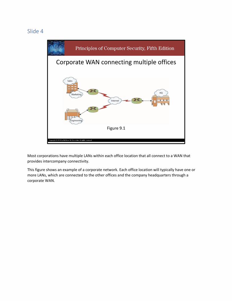
Most corporations have multiple LANs within each office location that all connect to a WAN that
provides intercompany connectivity.
This figure shows an example of a corporate network. Each office location will typically have one or
more LANs, which are connected to the other offices and the company headquarters through a
corporate WAN.

Slide 5
Over time, as networks have grown, diversified, and multiplied, the line between LAN and WAN has
become blurred. To better describe emerging, specialized network structures, new terms have been
coined to classify networks based on size and use:
A campus area network (CAN) is a network connecting any number of buildings in an office or university
complex (also referred to as a campus wide area network).
An intranet is a “private” network that is accessible only to authorized users. Many large corporations
host an intranet to facilitate information sharing within their organization.
The Internet is _the_ global network connecting hundreds of millions of systems and users.
A Metropolitan area network (MAN) is a network designed for a specific geographic locality such as a
town or a city.
A storage area network (SAN) is a high-speed network connecting a variety of storage devices such as
tape systems, RAID arrays, optical drives, file servers, and others.
A Virtual local area network (VLAN) is a logical network allowing systems on different physical networks
to interact as if they were connected to the same physical network.
A Client/server network is a network in which powerful, dedicated systems called servers provide
resources to individual workstations or clients.
A Peer-to-peer network is a network in which every system is treated as an equal, such as a home
network.

Slide 6
Thank you and take care.

Network Fundamentals: Network Topology
Slide 1
Howdy! In this video, we introduce network topologies.

Slide 2
The Topology of a network is how the network is physically or logically arranged.
The four main classes of network topologies are: Star, Bus, Ring, and Mixed

Slide 3
In a Star topology, components are connected to a central point, like the spokes on a wheel. All the
inter-component communication goes through the hub in the middle.

Slide 4
In a Bus topology, the components connected to the same cable, often called “the bus” or “the
backbone”. All inter-component communication uses the same medium, so care must be taken to avoid
collisions, or components trying to talk at the same time.

Slide 5
In a Ring topology, the components are connected to each other in a closed loop with each device
directly connected to two other devices. All inter-component communication which requires more than
1 hop is routed through other devices on the ring.
Slide 6
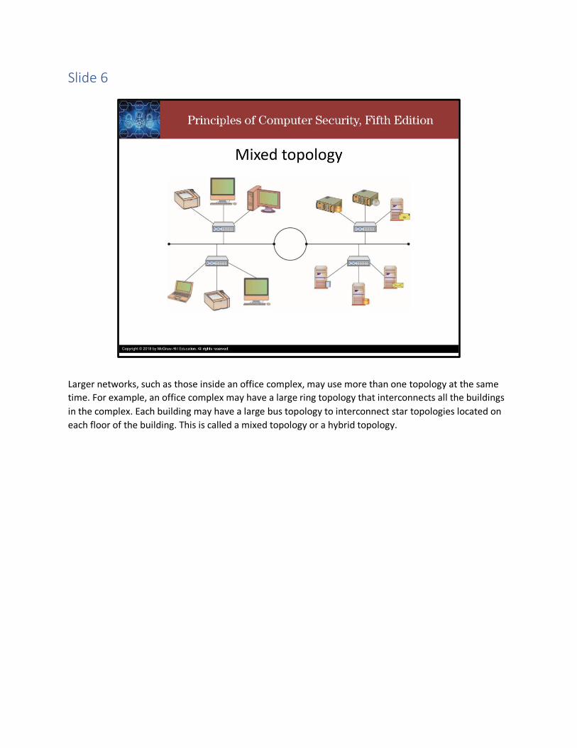
Larger networks, such as those inside an office complex, may use more than one topology at the same
time. For example, an office complex may have a large ring topology that interconnects all the buildings
in the complex. Each building may have a large bus topology to interconnect star topologies located on
each floor of the building. This is called a mixed topology or a hybrid topology.
Slide 7
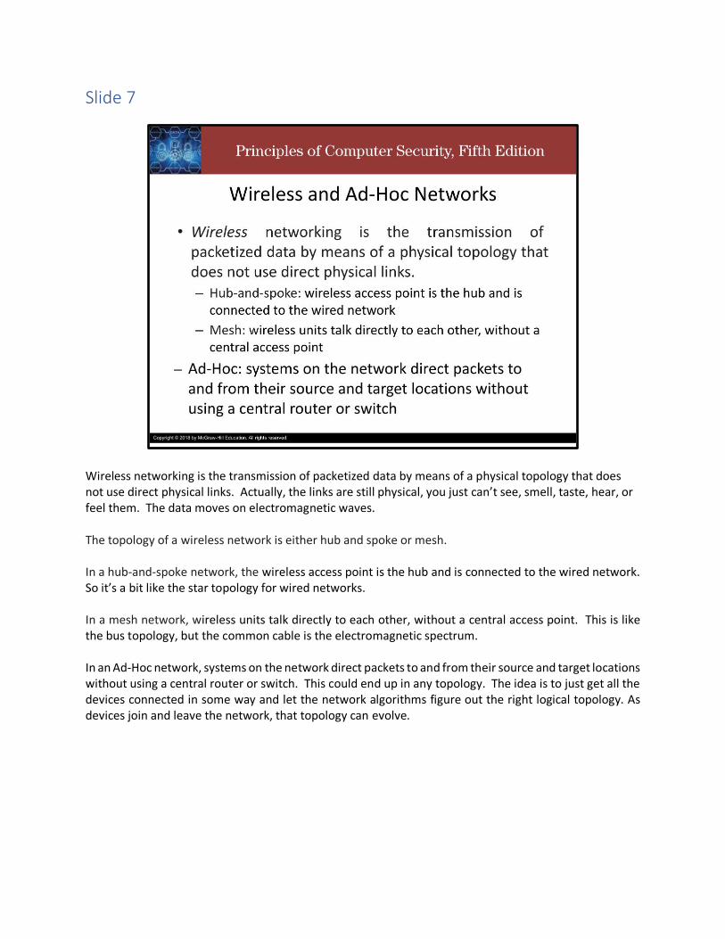
Wireless networking is the transmission of packetized data by means of a physical topology that does not use direct physical links. Actually, the links are still physical, you just can’t see, smell, taste, hear, or feel them. The data moves on electromagnetic waves.
The topology of a wireless network is either hub and spoke or mesh. In a hub-and-spoke network, the wireless access point is the hub and is connected to the wired network. So it’s a bit like the star topology for wired networks. In a mesh network, wireless units talk directly to each other, without a central access point. This is like the bus topology, but the common cable is the electromagnetic spectrum. In an Ad-Hoc network, systems on the network direct packets to and from their source and target locations without using a central router or switch. This could end up in any topology. The idea is to just get all the devices connected in some way and let the network algorithms figure out the right logical topology. As devices join and leave the network, that topology can evolve.

Slide 8
Thank you and take care.

Network Fundamentals: Network Protocols
Slide 1
Howdy! In this video, we introduce network protocols.
Slide 2
When engineers first started to connect computers together via networks, they quickly realized they
needed a commonly accepted method for communicating—a protocol.
A protocol is an agreed-upon format for exchanging or transmitting data between systems.
A protocol defines a number of agreed-upon parameters, such as the data compression method, the
type of error checking to use, and mechanisms for systems to signal when they have finished either
receiving or transmitting data.
Most networks are dominated by the Ethernet and Internet protocols.

Slide 3
There is a wide variety of protocols, each designed with certain benefits and uses in mind. Some of the
more common protocols that are used in networking are shown here:
Asynchronous Transfer Mode (ATM) is a telecommunications protocol based on transferring data in
fixed-size packets. The fixed packet sizes help ensure that no single data type monopolizes the available
bandwidth.
Ethernet is the LAN protocol developed jointly by Xerox, DEC, and Intel. It is the most widely
implemented LAN standard.
Fiber Distributed Data Interface (FDDI) is a protocol for sending digital data over fiber-optic cabling.
The Internet Protocol (IP) is the principal communications protocol in the Internet protocol suite for
relaying datagrams across network boundaries. Its routing function enables internetworking, and
essentially establishes the Internet.
The Transmission Control Protocol (TCP) is one of the main protocols of the Internet protocol suite. It
originated in the initial network implementation in which it complemented the Internet Protocol (IP).
Therefore, the entire suite is commonly referred to as TCP/IP. TCP provides reliable, ordered, and error-
checked delivery of a stream of octets (bytes) between applications running on hosts communicating via
an IP network. Major internet applications such as the World Wide Web, email, remote administration,
and file transfer rely on TCP, which is part of the Transport Layer of the TCP/IP suite. TLS often runs on
top of TCP.

Signaling System No. 7 (or SS7) is a set of telephony signaling protocols developed in 1975, which is used
to set up and tear down telephone calls in most parts of the world-wide public switched telephone
network. The protocol also performs number translation, local number portability, prepaid billing, SMS,
and other services.
Token Ring – A LAN protocol developed by IBM that requires systems to possess the network “token”
before transmitting data.
Slide 4
The OSI model, or OSI Reference Model, is an International Organization for Standardization (ISO)
standard for worldwide communications that defines a framework for implementing protocols and
networking components in seven distinct layers, shown in the figure.
The OSI model also provides a certain level of abstraction and isolation for each layer, which only needs
to know how to interact with the layer above and below it. The application layer, for example, only
needs to know how to communicate with the presentation layer—it does not need to talk directly to the
physical layer.
Control is passed from one layer to another from top-down before it exits one system and enters
another system, where control is passed from the bottom-up to complete the communications cycle.
Slide 5
Networks are built to share information and resources, but like other forms of communication, networks
and the protocols they use have limits and rules that must be followed for effective communication.
Large chunks of data must typically be broken up into smaller, more manageable chunks before they are
transmitted from one computer to another.
Advantages of breaking the data up include more effective sharing of bandwidth with other systems and
not needing to retransmit the entire dataset if there is a problem in transmission.
Each of the smaller pieces is typically called a packet.
Each protocol has its own packet format dictating how much data can be carried, what information is
stored where, how the packet should be interpreted by another system, and so on.A standard packet
structure is a crucial element in a protocol definition. Without a standard packet structure, systems
would not be able to interpret the information coming to them from other systems.
Slide 6
When transmitting packets across a network, there are many intervening protocols and pieces of
equipment, each with its own set of limitations.
The Maximum Transmission Unit (or MTU) is a factor in determining the number of packets into which a
message must be broken.
It represents the largest packet that can be carried across a network channel.
The value of the MTU is used by TCP to prevent packet fragmentation at intervening devices
Packet fragmentation is the splitting of a packet while in transit into two packets so that they fit past an
MTU bottleneck.
Slide 7
Built into the Internet Protocol is a mechanism for handling of packets that are larger than allowed
across a hop. Under ICMP v4, a router has two options when it encounters a packet that is too large for
the next hop: break the packet into two fragments, sending each separately, or drop the packet and
send an ICMP message back to the originator, indicating that the packet is too big. When a fragmented
packet arrives at the receiving host, it must be reunited with the other packet fragments and
reassembled. One of the problems with fragmentation is that it can cause excessive levels of packet
retransmission as TCP must retransmit an entire packet for the loss of a single fragment.

Slide 8
In IPv6, to avoid fragmentation, hosts are required to determine the minimal path MTU before
transmission of packets to avoid fragmentation en route. Any fragmentation requirements in IPv6 are
resolved at the origin, and if fragmentation is required, it occurs before sending.
IP fragmentation can be exploited in a variety of ways to bypass security measures. Packets can be
purposefully constructed to split exploit code into multiple fragments to avoid IDS detection. Because
the reassembly of fragments is dependent upon data in the fragments, it is possible to manipulate the
fragments to result in datagrams that are too large which can result in denial of service.
Slide 9
Thank you and take care.