Embed Size (px)
Citation preview

Aurora Energy Limited Network Connection Requirements
Network Connection Standard 9 May 2016

Aurora Energy Limited Network Connection Requirements
Doc ID Suite Author Approver Issued Version Page
AE-S014 Aurora Energy Commercial Mgr GM AM 9/5/2016 1.0 i of ii
© 2014 Aurora Energy Ltd Warning: Printed documents are UNCONTROLLED
Table of Contents
1 Purpose ................................................................................................................................................ 1
2 Scope ................................................................................................................................................... 1
3 Accountabilities ................................................................................................................................. 1
4 Definitions ............................................................................................................................................ 1
5 Relationship between Aurora and Delta ...................................................................................... 3
6 Applications for new Network Connections................................................................................. 3
6.1 Subdivisions & Multi-Tenanted Buildings ................................................................................ 3
7 Modifications to Existing Network Connections ........................................................................... 3
7.1 Capacity Changes ................................................................................................................... 3
8 Approval to Connect ........................................................................................................................ 3
8.1 New Installation .......................................................................................................................... 3
8.2 Replacement of Mains and Associated Equipment .......................................................... 4
9 Network Connections ....................................................................................................................... 4
9.1 Low Voltage Connections ....................................................................................................... 4
9.2 Secondary Network Connections & High Voltage Customers ......................................... 5
10 Standard Connection Capacities .............................................................................................. 5
10.1 ‘Low Capacity’ Connections .................................................................................................. 6
10.2 Unmetered Connections ......................................................................................................... 6
11 Ownership Boundaries .................................................................................................................. 7
11.1 General Provisions ..................................................................................................................... 7
11.2 Point of Supply ............................................................................................................................ 7
11.3 Ownership of Customer Substation Civil Works ................................................................... 7
11.4 Maintenance Responsibility .................................................................................................... 7
11.5 Easements ................................................................................................................................... 7
12 Connections General ................................................................................................................... 8
12.1 Connection Overloads ............................................................................................................. 8
12.2 Multiple Connections ................................................................................................................ 8
13 Customer Loads ............................................................................................................................. 8
13.1 Notifiable Loads ......................................................................................................................... 8
13.2 Motor Starting ............................................................................................................................. 9
13.3 Load Power Factor .................................................................................................................... 9
13.4 Voltage ........................................................................................................................................ 9
13.5 Voltage Fluctuations ............................................................................................................... 10
13.6 Harmonic Disturbances .......................................................................................................... 10
13.7 Capacitors ................................................................................................................................ 10
13.8 Load Control ............................................................................................................................. 11
14 Low Voltage Mains ...................................................................................................................... 11
14.1 Mains & Circuit Sizing .............................................................................................................. 11

Aurora Energy Limited Network Connection Requirements
Doc ID Suite Author Approver Issued Version Page
AE-S014 Aurora Energy Commercial Mgr GM AM 9/5/2016 1.0 ii of ii
© 2014 Aurora Energy Ltd Warning: Printed documents are UNCONTROLLED
14.2 Aerial Low Voltage Mains ...................................................................................................... 11
14.3 Low Voltage Mains in Underground Areas ......................................................................... 12
14.4 Low Voltage Underground Mains in an Overhead Area ................................................ 12
14.5 Supply via Unmetered Sub-circuit ........................................................................................ 13
15 Fault Level Considerations ......................................................................................................... 13
15.1 Customer Contribution to Fault Levels ................................................................................ 14
16 Electrical Protection .................................................................................................................... 14
16.1 Protection of Low Voltage Mains Connected to Low Voltage Distribution ................ 14
16.2 Protection of LV Mains from a Transformer ......................................................................... 14
16.3 Protection of High Voltage Mains ........................................................................................ 14
16.4 Protection against Unbalanced Voltage ........................................................................... 15
16.5 Protection of Sensitive Equipment ....................................................................................... 15
17 Metering ........................................................................................................................................ 15
18 Secondary Networks and High Voltage Customers ............................................................. 15
19 Distributed Generation ............................................................................................................... 16
20 Costs for Establishing Network Connections .......................................................................... 17
20.1 Cost Responsibilities................................................................................................................. 17
20.2 Enhanced Supply .................................................................................................................... 17
20.3 Cost-sharing on Joint-use Customer Substations ............................................................... 17
20.4 Temporary Supply .................................................................................................................... 17
21 Substations on Customer’s Property ........................................................................................ 18
21.1 General Requirements ........................................................................................................... 18
21.2 Space Requirements .............................................................................................................. 19
22 References .................................................................................................................................... 20

Aurora Energy Limited Network Connection Requirements
Doc ID Suite Author Approver Issued Version Page
AE-S014 Aurora Energy Commercial Mgr GM AM 9/5/2016 1.0 1 of 26
© 2014 Aurora Energy Ltd Warning: Printed documents are UNCONTROLLED
1 Purpose
All connections on the Aurora electrical distribution network (the Network) are subject to the
contractual terms of a Use-of-System Agreement which, among other things, requires that all
Customers covered by the agreement comply with Aurora’s network connection standards.
Accordingly, this standard defines the requirements that must be complied with, on a continuing
basis, for all Customer installations connected to the Network.
2 Scope
This standard applies to new and existing connections to Aurora’s networks located in the Dunedin
Area, Central Area, and Te Anau Area.
These requirements will be amended periodically, to reflect changes required for continued
compliance with legislation and good industry practice. It is the responsibility of installation owners
to ensure that compliance with these requirements is maintained at all times. The current version of
these requirements will be maintained on Aurora’s website (www.auroraenergy.co.nz), and will apply
from the date of publication.
3 Accountabilities
Commercial
Manager
(Delta)
Accountable for ensuring this document is current and published on
Aurora’s website.
Electricity
Retailers
Accountable for ensuring that its Customer contracts carry an
undertaking that the Customer will comply with this standard.
Customers Accountable for complying with this standard.
4 Definitions
Aspect. Definition.
Authorised
Network
Inspector
Means a registered electrical inspector who has been authorised by Aurora to
conduct the final connection of installations to the network.
Central Area means that part of the Aurora Network connected to Transpower via the Clyde,
Cromwell and Frankton grid exit points.
Certificate of
Compliance
has the meaning given in regulation 4 of the Electricity (Safety) Regulations
2010.
Certified Design means a design certified in accordance with regulation 58 of the Electricity
(Safety) Regulations 2010.
Code means the Electricity Industry Participation Code.
Connection
Capacity
means the maximum load, in kVA, that a connection is designed to serve. The
Connection Capacity is synonymous with the Assessed Capacity, as defined in
Aurora’s Use-of-System Pricing Methodology.

Aurora Energy Limited Network Connection Requirements
Doc ID Suite Author Approver Issued Version Page
AE-S014 Aurora Energy Commercial Mgr GM AM 9/5/2016 1.0 2 of 26
© 2014 Aurora Energy Ltd Warning: Printed documents are UNCONTROLLED
Customer means the person, or organisation, for whom Aurora will provide the new or
upgraded connection. The term Customer is to be read synonymously with the
terms “consumer”, “developer” or “subdivider” that may be in use in other
policy documents.
Customer
Network
means an electricity distribution network that is owned by someone other than
Aurora, where consumers connected to it are not switchable and therefore
have no choice of retailer.
Dunedin Area means that part of the Aurora Network connected to Transpower via the
Halfway Bush and South Dunedin grid exit points.
Electrical Safety
Certificate
has the meaning given in regulation 4 of the Electricity (Safety) Regulations
2010.
Embedded
Network
means an electricity distribution network that is owned by someone other than
Aurora, where consumers have ICPs allocated and managed by the
embedded network owner acting as the distributor for that network (or another
distributor appointed for that purpose), and the electricity traded is reconciled
at the point of connection between the embedded network and Aurora, by
the embedded network owner who must be certified as a reconciliation
participant in accordance with the Code.
Installation has the meaning given in section 2(1) of the Electricity Act 1992.
Mains has the meaning given in regulation 4 of the Electricity (Safety) Regulations
2010.
MCCB means moulded case circuit breaker.
MEP means Metering Equipment Provider.
Metering Point means the location within a Customer's installation where the MEP’s equipment
is installed.
Network
Extension
Means an electricity distribution network that is owned by someone other than
Aurora, where consumers have ICPs allocated and managed by Aurora, and
the electricity traded is reconciled at the NSP for Aurora at the grid exit point
(GXP)
Network Supply
Point
means the point at which a Secondary Network connects to the Aurora
network.
NZECP means a New Zealand Electrical Code of Practice.
Point of Common
Coupling
means the point in the Network, electrically nearest to the Customer, at which
other Customers are or may be connected.
Point of Supply has the meaning given in section 2(3) of the Electricity Act 1992.
Residential means areas that are zoned residential in the relevant Local Authority District
Plan, including rural residential.
Retailer means an electricity retailer that has a valid Use-of-System contract with Aurora.
Rural means areas zoned rural in the relevant Local Authority District Plan.
Secondary
Network
means an electricity distribution network that is connected to the Aurora
network, but owned, operated and maintained by a person other than Aurora.
Te Anau Area means that part of the Network connected to The Power Company network via
the Heritage Estate network supply point.
Temporary Supply means a temporary connection given to builders and other tradespeople for
the purposes of providing electricity supply at a worksite where there are no
existing electricity network supplies available.
Urban means developed areas that are not zoned rural in the relevant Local Authority
District Plan.

Aurora Energy Limited Network Connection Requirements
Doc ID Suite Author Approver Issued Version Page
AE-S014 Aurora Energy Commercial Mgr GM AM 9/5/2016 1.0 3 of 26
© 2014 Aurora Energy Ltd Warning: Printed documents are UNCONTROLLED
5 Relationship between Aurora and Delta
Aurora owns the electricity distribution network (Network) in Dunedin and Central Otago. Aurora
contracts Delta Utility Services Ltd (Delta) to manage and operate the Network on its behalf.
6 Applications for new Network Connections
All applications for new connections to the Network shall be made using a Connection Application
form (AE-F008), available at Delta offices and from www.auroraenergy.co.nz.
Applications shall include details of any notifiable loads as defined in section 13.1.
6.1 Subdivisions & Multi-Tenanted Buildings
Applications for connections required to support developments where electricity connections may
not be immediately completed (subdivisions, individually metered commercial or industrial buildings
etc) shall be made using a Network Development Application form (AE-F010), available at Delta
offices and from www.auroraenergy.co.nz.
7 Modifications to Existing Network Connections
Existing Customers shall seek approval, using a Connection Application form, before proceeding with
any of the following work:
Installation of any notifiable loads as defined in Section 13.1.
Replacement of all or part of the mains.
7.1 Capacity Changes
Customers shall submit a Connection Capacity Change Request form (AE-F009), available at Delta
offices and from www.auroraenergy.co.nz, when proposing to:
increase the installation load beyond the existing assessed capacity of the connection; or
install a load limiting circuit breaker to obtain a low capacity connection as detailed in
Section 10.1.
8 Approval to Connect
8.1 New Installation
The following conditions shall be fulfilled before a connection will be livened:
The Customer has entered into an agreement with a Retailer to purchase electricity;
The installation complies with the Electricity (Safety) Regulations 2010; including, but not
limited to:
The installation has been constructed in a manner that observes electrical safe distances,
in accordance with regulation 17;
The installation has been tested in accordance with regulations 63 or 64;
A Certificate of Compliance has been issued in accordance with regulation 65;
The installation has been inspected in accordance with regulation 70;
An Electrical Safety Certificate has been issued in accordance with regulation 74A; and

Aurora Energy Limited Network Connection Requirements
Doc ID Suite Author Approver Issued Version Page
AE-S014 Aurora Energy Commercial Mgr GM AM 9/5/2016 1.0 4 of 26
© 2014 Aurora Energy Ltd Warning: Printed documents are UNCONTROLLED
Documentation and records are available, in accordance with Part 5 of the regulations;
The mains and metering has been inspected by an Authorised Network Inspector, and
verified as complying with the Electricity (Safety) Regulations 2010 and Aurora requirements;
and
The customer has paid any capital contribution required for the establishment or upgrade of
the connection.
8.2 Replacement of Mains and Associated Equipment
Despite the provisions of regulations 6A and 59(3) of the Electricity (Safety) Regulations 2010, which
permit the maintenance and “like-for-like” replacement of fittings associated with mains to be
classified as general prescribed electrical work and therefore not subject to inspection, Aurora will
still require that mains replacement, mains entry box replacement, and similar activities be tested
and inspected by an Authorised Network Inspector, prior to reconnection.
This is considered necessary due to the relatively high number of instances where incorrect polarity is
detected during inspection.
This does not relieve the person carrying out the maintenance / replacement from the obligation to
test their work.
9 Network Connections
The type of Network connection provided for a Customer will be dependent upon the connection
capacity required, the position of the Customer's main switchboard, and the location and nature of
the Customer's property.
All connections shall be designed so as to minimise the extent to which Aurora assets will be placed
on private property.
9.1 Low Voltage Connections
Low voltage connections are generally made by connection of a low voltage service main to the
low voltage distribution system, or by connection to the low voltage side of a transformer located on
the Customer's premises.
The requirement for a transformer depends upon the connection capacity required, the capacity
and present loading on existing low voltage distribution circuits in the vicinity of the installation, and
the distance from the Customer’s property boundary to the Customer’s main switchboard. Each
connection application will be considered individually and the most appropriate connection
method chosen. Guidance on the connection capacities usually available is as follows:
9.1.1 Urban Areas
The maximum capacity for a particular installation will depend upon the capacity of the low voltage
Network in the vicinity but, generally, connection capacities of up to 3 phase 100 amps will be
available from the low voltage distribution system. Connection capacities of between 100 and 400
amps may require the installation of a transformer; however some locations may support connections
of up to 400 amps directly onto the low voltage distribution system. Connection capacities in excess
of 400 amps (>276kVA) will require the installation of a transformer.
The Customer may be required to make a capital contribution toward the cost of establishing the
new connection, and may be required to grant easements in gross, in favour of Aurora, over land on
which Aurora assets will be placed in order to provide the connection.

Aurora Energy Limited Network Connection Requirements
Doc ID Suite Author Approver Issued Version Page
AE-S014 Aurora Energy Commercial Mgr GM AM 9/5/2016 1.0 5 of 26
© 2014 Aurora Energy Ltd Warning: Printed documents are UNCONTROLLED
9.1.2 Rural Areas
In many rural areas, the high voltage distribution is 2-wire, and only single-phase supply is available.
In those areas, the largest connection capacity available without upgrading the high voltage
distribution to 3-phase is 50kVA single phase.
Where a Customer requires a new supply located further than 150 metres from an existing
transformer, a new, closer, transformer will be required. This transformer can be located on a pole in
the road reserve, with the Customer taking supply via low voltage Mains. In situations where the
Customer’s main switchboard is further than 150 metres from a high voltage line in the road reserve,
the most economic solution is usually the installation of a high voltage line across the Customer’s
property to a transformer close to the main switchboard.
The Customer may be required to make a capital contribution toward the cost of establishing the
new connection, and may be required to grant easements in gross, in favour of Aurora, over land on
which Aurora assets will be placed in order to provide the connection.
9.1.3 Temporary Supplies
A Temporary Supply shall be treated as being a Customer installation, and must be located on
property owned by the Customer.
Temporary supplies shall be allocated an ICP and may be metered or unmetered according to the
requirements of the responsible retailer.
The connection between the temporary supply switchboard / meter box and the distribution system
shall be by means of Customer/contractor owned mains in order to provide a clear demarcation
between Aurora’s networks and the Customer’s installation.
Temporary supply switchboards / meter boxes shall be completely self-supported and shall not, under
any circumstances, be fixed to Aurora’s assets. This includes, but is not limited to, Aurora’s distribution
service pillars, cabinets, transformers and poles.
Sites where multiple temporary low voltage supplies are needed require separate ICP’s to be
established.
9.2 Secondary Network Connections & High Voltage Customers
Customers may elect to establish a high voltage Secondary Network, where the Customer owns all
assets downstream of the Network Supply Point. This is generally only economic for capacities in
excess of 1,000 kVA, or when the Customer has a special need for high voltage.
Aurora distributes high voltage electricity at 11,000 and 6,600 volts - the voltage used will be the
voltage available in the area. It should be noted that Aurora has long-term plans to migrate its
distribution from 6,600 volts to 11,000 volts, and recommends that high voltage customers install dual
ratio transformers areas with 6,600 volt supply.
High voltage Secondary Networks have specific requirements, which are detailed in Section 18.
10 Standard Connection Capacities
Aurora’s use-of-system charges are based on the assessed capacity of the connection. The standard
connection capacities for connections up to 276kVA are generally determined by the size of service
fuse used to protect the Customer’s Mains. The installed standard distribution transformer size will
generally be used to determine the assessed capacity for connections greater than, or equal to,
300kVA. The maximum transformer size installed on the network is limited to 1,000kVA. Where
capacity greater than 1,000kVA is required, multiple transformers will be required.

Aurora Energy Limited Network Connection Requirements
Doc ID Suite Author Approver Issued Version Page
AE-S014 Aurora Energy Commercial Mgr GM AM 9/5/2016 1.0 6 of 26
© 2014 Aurora Energy Ltd Warning: Printed documents are UNCONTROLLED
Standard connection capacities are shown in Table 1 below:
Fuse Size Notes 1 Phase 2 Phase 3 Phase
63A 5A MCCB 1kVA**
63A 20A MCCB ≤ 15kVA*
63A 35A MCCB ≤ 8kVA* ≤ 24kVA*
63A ≤ 15kVA ≤ 28kVA ≤ 41kVA
100A ≤ 23kVA ≤ 69kVA
150A ≤ 103kVA
200A ≤ 138kVA
250A ≤ 173kVA
300A ≤ 207kVA
400A ≤ 276kVA
* Reduced capacity connection with load limiting circuit breaker – refer section 10.1
** Unmetered connection – refer section 10.2.
Table 1 - Standard Connection Capacities
It should be noted that the assessed capacities of connections do not represent a guaranteed
service level. There may be instances, especially during periods of high network loading, where the
full assessed capacity is not available. This is particularly true for residential connections, where the
distribution network is generally designed using an after diversity maximum demand that is much
lower than the assessed capacity.1
10.1 ‘Low Capacity’ Connections
The lowest available connection capacity is usually 15kVA single phase (determined by a 63 amp
service fuse). Special low capacity connections of 8kVA (32A) single phase, 15kVA (20A) three
phase, or 24kVA (32A) three phase can be made if the Customer installs, at their cost, a load-limiting
circuit breaker upstream of the Installation metering. The circuit breaker shall automatically
disconnect the supply of electricity should the rated connection current be exceeded. The load-
limiting circuit breaker shall have provision to be sealed and be of the 6kA ‘C’ curve type with tripping
5-10 times the rated current.
10.2 Unmetered Connections
Small capacity fixed loads such as telephone box supplies require no meter. To qualify for an
unmetered supply, the load shall be less than 1kVA and consist of fixed wired equipment with a
predictable annual energy usage in order to comply with the Code. Load details are to be provided
on the LV Connection Application form. The installation main isolator shall be a 5 amp MCCB.
A low-voltage, single-phase, 15kVA builders temporary supply connections may be unmetered,
subject to the following conditions:
The purpose of the temporary supply must be for a builder’s temporary supply only.
All power outlets are to be supplied from RCD devices (residual current protection).
If the connection is still required after 6 months, a re-inspection fee will apply, and for every
subsequent 6 months.
1 After diversity maximum demand (ADMD) is the simultaneous maximum electrical demand (kVA) of a group of Customers,
divided by the number of Customers. ADMD allows the electrical network to be planned and constructed to service existing
connections, as well as making reasonable provision for future connection and load growth. Use of ADMD allows network to
be built economically, and at much lower costs than if the maximum demand of each individual connection was considered.
Accordingly, use of ADMD in the design process limits the network costs that must be recovered from Customers in the form
of line charges.

Aurora Energy Limited Network Connection Requirements
Doc ID Suite Author Approver Issued Version Page
AE-S014 Aurora Energy Commercial Mgr GM AM 9/5/2016 1.0 7 of 26
© 2014 Aurora Energy Ltd Warning: Printed documents are UNCONTROLLED
11 Ownership Boundaries
11.1 General Provisions
In order to define maintenance responsibilities and allocate capital costs, it is necessary to define
the boundaries between fittings that are part of the Network, and fittings that are part of a
Customer’s installation. Aurora has applied the provisions of the Electricity Act 1992 in establishing
the following rules for determining the ownership boundaries of new assets.
11.2 Point of Supply
All assets upstream of the Point of Supply will be owned by Aurora, unless specifically agreed
otherwise in writing. Figure 3 to Figure 9 shows the Point of Supply for a range of supply configurations.
The following fittings will be owned by Aurora, irrespective of who owns the property they are located
on:
Incoming high voltage switchgear, where the Customer elects to take supply at high voltage.
High voltage substation equipment and high voltage lines and cables, unless this equipment
is owned by a Customer that takes supply at high voltage.
The low voltage mains protection device; i.e., service fuse-holder and fuse link, or circuit
breaker.
All low voltage distribution on a private property that is for the exclusive use of one Customer shall be
owned by the Customer, from the point of supply. This means that when supply to a Customer crosses
a neighbour’s property, the Customer is required to arrange an easement in favour of Aurora, over
the neighbour’s property.
Low voltage distribution on a private property that supplies multiple properties will be owned by
Aurora and easements in favour of Aurora will be required over this distribution.
Low voltage distribution on a private property that supplies multiple Customers on the property (e.g.,
a unit title development) will generally not be owned by Aurora, but Aurora may take ownership if
the low voltage distribution is installed in a right of way and easements in favour of Aurora are
created.
Where an existing service property is further subdivided, the mains cables (overhead or underground)
intended to supply each lot must be completely contained within the lot that it serves. In some cases
this will require relocation of the cable serving the existing installation.
11.3 Ownership of Customer Substation Civil Works
For substations on a Customer’s property, the transformers, standard concrete pads, associated
switchgear and earthing facilities are part of the Network. Specialist foundations, buildings or other
weather and physical protective facilities are owned by the Customer.
Specific details of the requirements relating to substations on Customer property are contained in
Aurora policy NS 5.11 Substations in Customer Buildings Requirements.
11.4 Maintenance Responsibility
Maintenance of fittings that are part of the electrical Installation is the responsibility of the Installation
owner. All fittings on a Customer’s property that are part of the Network, including all high voltage
mains owned by Aurora, will be maintained by Aurora. Customers shall provide access to authorised
Contractors to carry out maintenance.
11.5 Easements
Aurora requires a registered easement over private property that is occupied by fittings that form
part of the Network. Easements provide Aurora with access rights for the purpose of maintenance

Aurora Energy Limited Network Connection Requirements
Doc ID Suite Author Approver Issued Version Page
AE-S014 Aurora Energy Commercial Mgr GM AM 9/5/2016 1.0 8 of 26
© 2014 Aurora Energy Ltd Warning: Printed documents are UNCONTROLLED
or replacement of the fittings, and place certain restrictions on the property owner to safeguard the
fittings; e.g., limiting erection of buildings, or planting of trees, close to the fittings. Easements also
afford the land owner legal protection with respect to property damage caused by Aurora or its
contractors. Further information is available in the Electricity Easements policy.
12 Connections General
12.1 Connection Overloads
For Customers supplied via low voltage fuse or MCCB protection, the connection capacity is
generally determined by the protection rating. If the Customer's load exceeds the protection rating,
protection operation can result.
For Customers supplied at low voltage via direct connection to the low voltage terminals of a
transformer (refer Section 16.2), the connection capacity of the connection is the transformer rating.
Transformers have some overload capacity, and Customers are permitted to utilise this, subject to
the transformer loading not exceeding 120% of its rating and the overload being of a temporary
nature unlikely to shorten the useful life of the transformer. The Customer's incoming circuit breaker
overcurrent protection shall be set to operate at, or less than, this value. The Customer's mains and
main switch must be rated to carry the overload. The loading on the transformer shall not exceed
the appropriate values for normal cyclic duty defined in British Standard Code of Practice CP1010
"Loading Guide for Oil-Immersed Transformers".
12.2 Multiple Connections
If the Customer has more than one ICP associated with the same property, the Customer shall not
parallel those connections, or provide any facilities to parallel the connections. This is to avoid the
possibility of back feeds creating hazards on the Network.
In all cases, each ICP must be able to be separately de-energised from the Network without affecting
the electricity supply to any other ICP’s present upon the same property.
13 Customer Loads
13.1 Notifiable Loads
The following work has special requirements and must be specifically notified:
Installing appliances subject to load control.
Installing charging facilities for plugin electric vehicles
Installing electric motors with capacities greater than the exempt ratings specified in Section
13.2, below. This includes appliances with motors, such as heat pumps and refrigeration units.
Installing an appliance that may affect the quality of supply to other Customers by the
introduction of harmonics, or by causing voltage fluctuations.
Installation of an individual load that exceeds 40% of the installation’s connection capacity
(6kW for a 15kVA connection).
Installation of capacitors that result in the total capacitive load of an installation exceeding
100 kVAr.
Installation of generators, including photo-voltaic panels – refer to Section 19.

Aurora Energy Limited Network Connection Requirements
Doc ID Suite Author Approver Issued Version Page
AE-S014 Aurora Energy Commercial Mgr GM AM 9/5/2016 1.0 9 of 26
© 2014 Aurora Energy Ltd Warning: Printed documents are UNCONTROLLED
13.2 Motor Starting
The starting of electric motors can cause severe voltage dips on the Network, resulting in irritation to
other Customers. In addition to complying with starting requirements, running motors with fluctuating
loads shall not cause excessive voltage fluctuation – refer to section 13.5.
13.2.1 Exempt Motor Sizes
AC motors, up to and including the ratings shown in Table 2 below, are not subject to starting current
limits and may be installed with direct-on-line starting without specific permission to connect.
Rural Urban
Residential Non-Residential
Single Phase (Not Exceeding) 0.75 kW 1.5 kW 2.2 kW
Three Phase (Not Exceeding) 4.0 kW 4.0 kW 7.5 kW
Table 2 - Schedule of Exempt Motor Sizes
13.2.2 Non-exempt Motor Sizes
All a.c. motors above the ratings specified in Table 2 shall be approved by Delta’s Asset Management
Group prior to connection. The criteria used for approval is that the relative voltage changes on
motor start-up shall not exceed the values in Table 3, below:
Frequency of Starting At Point of Common
Coupling
At Zone
Substation HV Bus
In excess of 10 starts per hour. 1% 0.5%
In excess of 3 starts per day, but not more
than 10 starts per hour. 3% 1.0%
Not more than 3 starts per day, including
not more than 1 start between the hours of
5 pm and 11 pm on any day.
6% 1.5%
Emergency equipment started
infrequently (e.g., fire pumps). 12% 2.0%
Table 3 - Schedule of maximum allowable voltage change during motor starting
In Installations where several large motors start automatically, the effect of these motors starting
simultaneously when supply is restored after a service interruption needs to be considered. Unless
delayed starting is installed to Aurora’s satisfaction, the relative voltage change will be assessed on
the basis of all motors on automatic control starting simultaneously.
13.3 Load Power Factor
The true power factor of a Customer’s Installation, measured at the metering point, shall not be less
than 0.95 lagging. For the purposes of this policy power factor is defined as true power factor kW/kVA
not displacement power factor cosθ.
13.4 Voltage
The Network will be designed and operated to maintain the Customer’s voltage within the limits
prescribed by Regulation 28 of the Electricity (Safety) Regulations 2010. The limit for low voltage is
230 volts ± 6% when measured at the Point of Supply.

Aurora Energy Limited Network Connection Requirements
Doc ID Suite Author Approver Issued Version Page
AE-S014 Aurora Energy Commercial Mgr GM AM 9/5/2016 1.0 10 of 26
© 2014 Aurora Energy Ltd Warning: Printed documents are UNCONTROLLED
13.5 Voltage Fluctuations
Some electric appliances, such as motors with fluctuating loads and welders, can cause voltage
fluctuations in the Network, resulting in annoyance to other Customers. Customer’s fittings and
appliances shall comply with Regulation 31 of the Electricity (Safety) Regulations 2010, and
specifically, shall not cause voltage fluctuations, at the Point of Supply, in excess of the compatibility
limits specified in AS/NZS 61000.3.11: 2002.
13.6 Harmonic Disturbances
Customer’s fittings and appliances shall comply with Regulation 31 of the Electricity (Safety)
Regulations 2010 and, specifically, shall not inject into the Network any harmonic distortions that
exceed the levels specified in NZECP36 (‘Harmonic Levels’). Harmonics are particularly prevalent in
variable speed motor drives.
Despite the requirements of NZECP36, Customers shall ensure that their fittings and appliances meet
the requirements of Aurora’s Harmonics Standard.
In the Dunedin area, the 1050Hz ripple frequency corresponds to the 21st harmonic. In addition to
the requirements of NZECP36, Customers' appliances shall not cause 1050Hz voltages in excess of
0.7% at the Point of Supply. Particular care needs to be taken with regard to appliances utilising solid
state inverters.
13.7 Capacitors
Capacitors are generally installed in a Customer’s installation to provide power factor correction,
either as part of a power factor correction unit or associated with individual appliances such as
motors or fluorescent light fittings. They can absorb ripple control signal, resulting in insufficient signal
strength to operate the Customer's and adjacent Customers' ripple control relays.
The excessive absorption of ripple control signals by capacitors shall be prevented by the installation
of suitably rated blocking chokes on the network side of individual capacitors or groups of appliances
containing capacitors.
Aurora operates a 317Hz ripple injection system in the Central Otago area. Generally the installation
of small power factor correction capacitors has little effect at this frequency, and capacitor banks
of up to 100kVAr may be installed without specific permission. For the installation of capacitor loads
above 100kVAr in the Central Otago area, specific permission shall be obtained. Delta’s Asset
Management Group will determine, in each case, if measures to prevent any problems are required.
The design, installation and operation of these measures shall be the responsibility of the Customer.
In the Dunedin area, Aurora operates a 1050Hz ripple injection system, and absorption of the ripple
signal can be reduced by the installation of 1050Hz blocking chokes on the Network side of individual
capacitors, or groups of appliances containing capacitors. Customers are permitted to install
unblocked capacitor kVAr capacity up to 2% of connection kVA capacity. For 3 phase connections,
the maximum kVAr, per phase, is 1/3 the total kVAr allowed. For capacitive loads exceeding this in
the Dunedin area, specific permission to connect shall be obtained. Delta’s Asset Management
Group will determine if 1050Hz blocking is required in each case. The Customer is responsible for the
provision and correct operation of the blocking chokes.
Although a 317Hz ripple injection system is being introduced in Dunedin, the prevalence of
installations with 1050Hz signalling equipment means that the Dunedin requirements, stated above,
will be maintained for some time.
Customers installing fluorescent lighting loads are advised to use fittings with lead-lag ballasts, which
will provide power factor correction without the risk of ripple signal absorption. Electronic fluorescent
lighting ballasts do not require capacitors for power factor correction, and do not absorb ripple
control signals.

Aurora Energy Limited Network Connection Requirements
Doc ID Suite Author Approver Issued Version Page
AE-S014 Aurora Energy Commercial Mgr GM AM 9/5/2016 1.0 11 of 26
© 2014 Aurora Energy Ltd Warning: Printed documents are UNCONTROLLED
13.8 Load Control
The facility to switch off certain loads at peak times allows Aurora to reduce costs associated with
peak loads, including Transpower charges. Customers with controlled loads pay lower annual line
charges, via retailer tariffs, in consideration of the controlled load being switched off during peak
times.
It is recommended that the following appliances be controlled:
Residential charging facilities for plug-in electric vehicles. These should be supplied from an 8
hour controlled circuit (service hours between 10pm and 7am).
Storage water heaters.
Residential storage water heaters above 135 litres.
Storage space heaters and underfloor heating.
Electric kilns.
Spa and swimming pools.
Irrigation pumps.
Modern load control relays can directly switch resistive loads up to 9kW. Older relays are limited to
6kW, and in some cases 4.7kW. Loads in excess of these values will require a contactor which shall
be supplied and installed at the Customer’s cost.
Customers must not employ devices that defeat the load control system by switching the controlled
load to uncontrolled circuits when, by contractual terms agreed with their electricity retailer, those
loads should be off.
Customers may install water heaters that contain a quick recovery system (a separate top element).
The quick recovery element must be connected to an uncontrolled circuit and configured so that it
provides a maximum “one-shot” boost duration of one hour, initiated via a manual switch / push-
button.
Note: Subject to changes in Aurora’s Use-of-System Pricing Methodology, if a Customer requires a 2
phase 63 amp (28kVA), or 3 phase 35 amp (24kVA), or one phase 100 amp (23kVA) supply to service
off peak controllable load, and the capacity above 15kVA is solely required to service off-peak load,
then for the purposes of line charges, the connection will be assessed at 15 kVA.
14 Low Voltage Mains
14.1 Mains & Circuit Sizing
The correct sizing of mains and sub-circuits is the Customer’s responsibility and shall be in accordance
with AS/NZS3000:2007.
It is recommended that all mains neutral conductors be the same size as the phase conductors. This
will reduce the chance of neutral conductor overloads due to imbalanced loads and harmonics.
14.2 Aerial Low Voltage Mains
Installation of new aerial low voltage service mains and the alteration of existing low voltage aerial
service mains may be controlled or prohibited by the relevant Local Authority's By-Laws and/or
District Plan.
Where permitted, aerial mains shall be copper conductor with a minimum cross-sectional area of 16
mm2. For open-pair mains, the phase conductors shall be covered with black PVC insulation and
the neutral conductor shall be bare. The Customer is responsible for providing supports for conductor
insulators and terminations on the property. The mains shall be installed in accordance with
AS/NZS3000:2007, Regulation 17 of the Electricity (Safety) Regulations 2010, and NZECP34 (Electrical

Aurora Energy Limited Network Connection Requirements
Doc ID Suite Author Approver Issued Version Page
AE-S014 Aurora Energy Commercial Mgr GM AM 9/5/2016 1.0 12 of 26
© 2014 Aurora Energy Ltd Warning: Printed documents are UNCONTROLLED
Safety Distances). It is recommended that neutral screened cable be used for aerial mains due to
the enhanced safety this provides.
The current carrying capacity of low voltage aerial mains shall be limited to 160A, being the
maximum standard fuse link size carried in approved pole top fuse-holders.
14.3 Low Voltage Mains in Underground Areas
Low voltage mains in areas with underground low voltage distribution will be connected via a low
voltage service pillar. Service pillars are available in 100, 200 and 400 amp capacities, and are
normally located on the street side of the Customer's property boundary. Delta’s Asset Management
Group will, after consulting with Customers, determine the position of the service pillar. In residential
areas service pillars are generally placed on the street frontage at the junction of two property
boundaries, allowing the pillar to serve two Customers.
Due to physical limitations, service pillars are generally not suitable for the termination of steel wire
armoured or paper insulated lead sheathed mains cable.
14.3.1 Service Pillar Terminations
The termination of low voltage mains into service pillars is Aurora’s responsibility. Customers shall
ensure that their mains cable is installed to the service pillar position with sufficient length to facilitate
termination. Copper and aluminium cables can be used for underground mains, but for 63 amp and
100 amp connections, aluminium cable cores will need to be terminated with copper tails via Al/Cu
transition joints. The maximum cables sizes for 63 amp and 100 amp connections are 35mm2 and
50mm2 respectively. If the mains exceed these sizes, then reduced size tails are required. The
Customer is responsible for providing tails and transition joints when required, which must be located
within the Customer’s property.
14.4 Low Voltage Underground Mains in an Overhead Area
In areas where the low voltage distribution is overhead, Customer mains can be connected directly
to pole-top fuses provided that the connection capacity is less than 150 amps, and the conditions in
Section 12 are complied with. In all other cases a boundary service pillar is required for the
termination of the Customer’s mains. This service pillar is then connected to the overhead network.
See Figure 2 for a diagram of the two connection options.
14.4.1 Pole-top Supply
This involves connection of the Customer’s underground mains directly to pole-top fuses, subject to
the following conditions:
A suitable pole must be available on the same side of the street as the Customer, located
within two metres of the Customer's lateral boundary, and within 5 metres of the general
property frontage (Figure 2).
The physical circumstances, such as ground levels and footpath conditions, must be suitable
for the installation of an underground cable.
All mains cables shall be copper neutral screened. Steel wire armoured cable is not
acceptable. The maximum conductor size is 95mm2.
The cable in the road reserve shall be laid parallel, or at right angles, to the street and the
cable shall cross the Customer's property boundary at a location determined by Delta’s Asset
Management Group that results in the minimum trenching in the road reserve. The Customer
shall provide the cable from the property boundary to the pole top connection. The total
cable length shall allow for the cabling in the road reserve, and for 9m of cable up the pole,
and shall be left coiled at the boundary for installation by the connection contractor.
The cable shall be mechanically protected to 2.5m above ground level, and the protection
shall continue 200mm below ground level. Where electrical conduit is used as mechanical

Aurora Energy Limited Network Connection Requirements
Doc ID Suite Author Approver Issued Version Page
AE-S014 Aurora Energy Commercial Mgr GM AM 9/5/2016 1.0 13 of 26
© 2014 Aurora Energy Ltd Warning: Printed documents are UNCONTROLLED
protection, grey or black high impact conduit shall be used with galvanised steel saddles and
stainless steel screws. The conduit and fixings shall be supplied by the Customer.
14.5 Supply via Unmetered Sub-circuit
When electricity is distributed through a building complex, such as a shopping mall, high-rise
apartments, or an office block, different occupiers of the building often require a separately metered
supply of electricity. This is achieved by the use of unmetered circuits such as rising mains, ring mains,
and sub-mains supplied from the installation main switchboard.
In order to limit kWh losses, the maximum voltage drop in unmetered circuits between the point of
supply and the metering point shall not exceed 2.5%.
Each occupier has a separately metered "network connection" onto an unmetered sub-circuit. These
unmetered sub-circuits are not part of the Aurora Network, but Aurora will supply the fuses for the
connection of individual Customers to an unmetered sub-circuit. The installation of these fuses is the
responsibility of the complex owner. The fuses will remain part of the Network, and will be sealed by
Aurora-authorised personnel. The fuses shall be accessible for Aurora and the Customer’s Retailer at
all times. Figure 15, on page 25, shows a typical unmetered sub-circuit configuration.
15 Fault Level Considerations
The short circuit rating of Customers’ equipment should be not less than the design fault level of the
Network to which it is connected. The choice of equipment for connection at low voltage may take
into account attenuation in the mains.
The Aurora 11kV and 6.6kV Networks are designed for a maximum short circuit level of 250MVA - 13kA
at 11kV and 22kA at 6.6kV. Customers taking supply at 11kV or 6.6kV shall design their installations
for a 250MVA prospective short circuit level.
For Customers supplied from the low voltage Network in residential areas, the prospective short circuit
levels at the Customer's main switchboard will typically be less than 6kA. For Customers supplied from
a dedicated transformer, the maximum prospective short circuit levels at the low voltage terminals
of the transformer will be in accordance with Table 4, below.
For the purposes of designing installations, Customers should use the figures provided in Table 4 or,
on request, a maximum prospective short circuit current can be provided for their point of supply.
Transformer Size
(kVA 3-Phase)
Maximum Prospective
Short Circuit Current (kA)
15 1
30 1.5
50 2
100 4
200 6.5
300 9.5
400 11
500 15
750 22
1,000 28
NB: For sizes not included, use the short circuit current of the next largest transformer shown.
Table 4 - Maximum Short Circuit Currents at Distribution Transformer LV Terminals (6.6kV & 11kV)

Aurora Energy Limited Network Connection Requirements
Doc ID Suite Author Approver Issued Version Page
AE-S014 Aurora Energy Commercial Mgr GM AM 9/5/2016 1.0 14 of 26
© 2014 Aurora Energy Ltd Warning: Printed documents are UNCONTROLLED
15.1 Customer Contribution to Fault Levels
Design of the Network will take into account the contribution to fault level by Customers’ apparatus,
such as large motor loads.
16 Electrical Protection
Regulation 32(1) of the Electricity (Safety) Regulations 2010 requires that every person supplying a
line function service to any Customer shall provide to that Customer a service protective device of
appropriate rating to provide protection against short circuits or earth faults on mains, while
AS/NZS3000:2007 requires that the maximum current in a cable must not exceed the current rating
of the conductor.
16.1 Protection of Low Voltage Mains Connected to Low Voltage Distribution
Mains will be protected by HRC fuses housed in service pillars or mounted at pole-top. The minimum
capacity fuse available is 63 amps, and the maximum 400 amps. Customers shall ensure that the
rating of their mains and main switchboard is greater than, or equal to, the service fuse rating. At
existing installations that have mains rated less than 63 amps, the Customer shall either provide
appropriate protection or upgrade the mains before any additional load is connected.
Connections to installations requiring a capacity less than 63 amps will be protected by 63 amp HRC
fuses and should be sized accordingly.
The protection of unmetered sub-circuits is the responsibility of the sub-circuit owner.
16.2 Protection of LV Mains from a Transformer
For connection capacities up to 276kVA (400A), mains protection will be provided by low voltage
HRC fuses or a MCCB mounted adjacent to the transformer.
If transformer capacity is greater than, or equal to, 300kVA and it is dedicated to supply one
Customer with no low voltage interconnection, the low voltage mains can be connected directly to
the transformer low voltage terminals. The transformer high voltage fuses will only provide short circuit
protection for the low voltage mains. Customers are required to provide low voltage mains overload
protection. To ensure the transformer high voltage fuses can detect phase-to-earth faults at the
Customer's main switchboard, the mains shall be sized to carry the rated current of the transformer
and be no longer than 20 metres. Distances longer than 20 metres will be subject to approval by
Delta’s Asset Management Group.
When a Customer is supplied from a transformer that is primarily for that Customer's use, but also has
an interconnection with the low voltage Network, the Customer's mains will be protected by HRC
fuses for connection capacities up to 400 amps, and by a MCCB for connection capacities between
400 and 800 amps.
Where supply is via paralleled transformers, inter-tripping from the high voltage fuse switch to the low
voltage incoming circuit breakers is required, to ensure faults on the transformer high voltage
windings are not back-fed via the low voltage bus.
16.3 Protection of High Voltage Mains
High voltage mains are generally protected by the feeder protection at the Network zone substation.
Each case will be subject to individual design and approval. The Customer's protection must be
designed to discriminate with the Network protection, such that faults within the Customer's
installation beyond the Customer's incoming circuit breaker or fuse switch will not normally result in
tripping of a zone substation feeder circuit breaker.

Aurora Energy Limited Network Connection Requirements
Doc ID Suite Author Approver Issued Version Page
AE-S014 Aurora Energy Commercial Mgr GM AM 9/5/2016 1.0 15 of 26
© 2014 Aurora Energy Ltd Warning: Printed documents are UNCONTROLLED
16.4 Protection against Unbalanced Voltage
It is possible for one or two fuses of a 3-phase set protecting mains or a transformer to operate,
resulting in Customers receiving an unbalanced or reduced voltage supply. If a Customer has
equipment that is vulnerable to damage by unbalanced or reduced voltage, they are advised to
install their own protection that will automatically disconnect the appropriate equipment. Aurora will
not accept responsibility for any damage to a Customer’s equipment caused by unbalanced
voltage.
16.5 Protection of Sensitive Equipment
Circumstances or events beyond Aurora’s control may cause unplanned service interruptions or
transient voltages (these are momentary fluctuation in voltage and sometimes referred to as ‘surges’
or ‘spikes’), potentially damaging equipment or appliances. These events include motor vehicle
incidents damaging network equipment, lightning strikes and storm damage.
Customers with sensitive equipment or appliances that may be affected by an unplanned service
interruption or transient voltage, which may include computers, televisions, phones, computerised
appliances and white-ware, should consider appropriate protection. Normally, this is achieved by
installing back-up devices or surge protectors, which can be plugged into appliances or wired into
the installation mains. Customers are also advised to arrange insurance that covers damage from
transient voltages.
Aurora will not accept liability for any damage or loss suffered by a Customer as a result of
momentary fluctuations in voltage or frequency of the electricity supply.
17 Metering
Customer shall provide appropriate space within their premises to accommodate metering
equipment. Metering equipment requirements will be defined by the Customer’s electricity retailer
(or the electricity retailer’s metering equipment provider).
Where the Customer’s connection capacity is greater than 149kVA but not half-hourly metered, the
Customer shall ensure that sufficient room is available in the meter enclosure for an additional meter
to measure control period demand.
18 Secondary Networks and High Voltage Customers
The owner of a Secondary Network is responsible for the maintenance and safe operation of the
Secondary Network, along with compliance with the Electricity Act 1992, Electricity (Safety)
Regulations 2010, and where applicable, the Code. For a new Secondary Network connection, the
owner will be required, as a condition of connection, to provide details of how they intend to
manage their compliance obligations.
Electricity Authority publication “Guidelines for Metering, Reconciliation and Registry Arrangements
for Secondary Networks”, available from the Authority’s website (www.ea.govt.nz), explains the
various characteristics of Secondary Networks, along with the obligations imposed on Secondary
Network owners.
Aurora will not connect any Secondary Network that is intended to be a Network Extension. Aurora
will not assume responsibility for the registry management of ICPs connected to a Secondary
Network.
Typical configurations for high voltage Secondary Network connections are indicated in Figure 16 to
Figure 19. Supply will be via an incoming isolation device such as a circuit breaker, isolator, or fuse-
switch supplied and maintained by Aurora, but the Customer shall provide suitable accommodation
for this equipment.

Aurora Energy Limited Network Connection Requirements
Doc ID Suite Author Approver Issued Version Page
AE-S014 Aurora Energy Commercial Mgr GM AM 9/5/2016 1.0 16 of 26
© 2014 Aurora Energy Ltd Warning: Printed documents are UNCONTROLLED
High voltage metering units incorporating current transformers and voltage transformers will generally
be required for all high voltage Secondary Network connections. All costs associated with metering
the connection will be the responsibility of the high voltage Secondary Network owner.
When supply is required from paralleled high voltage feeders to meet loading or security
requirements, special protection facilities will be required.
Owners of works (who may be high voltage Customers) with a distribution capacity of 10MVA or
greater must implement a safety management system in conformance with Regulations 47 to 56 of
the Electricity (Safety) Regulations 2010, and have the safety management system audited. Owners
of works (who may be HV Customers) with an installed distribution capacity of less than 10MVA must
ensure they have inspection, maintenance and record-keeping practices in place that comply with
Regulations 40 to 46 of the Electricity Safety Regulations 2010; however, they may voluntarily
implement an audited safety management system as an alternative.
Customers wishing to connect to the Aurora network and take supply at high voltage will be required
to:
furnish a copy of the Certified Design for the high voltage installation;
furnish a copy of a properly completed Certificate of Compliance covering the high voltage
installation;
furnish a copy of the record of testing in accordance with regulations 38 and 64 of the
Electricity (Safety) Regulations 2010;
furnish a copy of the record of inspection in accordance with regulation 72 of the Electricity
(Safety) Regulations 2010; and
furnish evidence that the owner of the high voltage installation has either an audited safety
management system in accordance with regulations 47 to 56 of the Electricity (Safety)
Regulations 2010, or has a management system in place that satisfies the requirements of
regulations 40 to 46 of the Electricity (Safety) Regulations 2010
High voltage Secondary Network connections may be metered at low voltage where all of the
following conditions are met:
The high voltage Secondary Network is a Customer Network as defined by the Electricity
Authority’s “Guidelines for Metering, Reconciliation and Registry Arrangements for Secondary
Networks”;
No more than one transformer is connected to the Customer Network; and
The low voltage metering point is immediately adjacent to the transformer and has a meter
which measures in half-hourly intervals.
The low voltage fuses will be owned by Aurora and the connection capacity will be based on the
low voltage fuse size or transformer capacity, as outlined in section 10.
Where any of the above conditions change for an LV metered HV Secondary Network connection,
the Secondary Network owner will be required, at their cost, to establish HV metering as close as
practicable to the Network Supply Point.
19 Distributed Generation
Distributed generation requirements are defined in Aurora’s Guide to Small Scale Distributed
Generation, Guide to Large Scale Distributed Generation, and Distributed Generation Technical
Standard. These documents are available on the Distributed Generation page of the Aurora website
(www.auroraenergy.co.nz), along with the associated application forms.

Aurora Energy Limited Network Connection Requirements
Doc ID Suite Author Approver Issued Version Page
AE-S014 Aurora Energy Commercial Mgr GM AM 9/5/2016 1.0 17 of 26
© 2014 Aurora Energy Ltd Warning: Printed documents are UNCONTROLLED
20 Costs for Establishing Network Connections
20.1 Cost Responsibilities
All costs associated with the Customer's installation are the responsibility of the Customer. In order to
establish a Network connection, Aurora may need to carry out additions or alterations to its Network,
and Customers may be required to make a contribution towards the cost of this work, in accordance
with the Capital Contributions policy.
When there is a choice of connection method, the method resulting in the lowest cost to Aurora shall
be used; however, if a Customer requires a connection method other than the method resulting in
the lowest cost to Aurora, the Customer shall make an additional contribution equal to the difference
in cost between the selected method and the lowest cost method. For a pole top mains connection,
the additional contribution is not required when the Customer supplies the cable from the property
boundary to the pole top fuses.
20.2 Enhanced Supply
When a Customer requires a supply with enhanced electrical characteristics or enhanced reliability
beyond that which would normally be provided, then the Customer shall meet the additional costs
incurred by Aurora in providing facilities to satisfy those requirements.
20.3 Cost-sharing on Joint-use Customer Substations
Any Customer requesting new or increased supply has the choice of paying for supply based on a
distribution substation located on their property, or elsewhere. Subject to the availability of practical
alternatives, it is not compulsory that Customers provide space on their property – the alternative
may simply be more expensive for them.
Where Aurora prefers (for reason of lower cost) a substation located on the Customer’s
property, and the Customer prefers to pay the higher cost of one located elsewhere, then
Aurora will charge the Customer based on the minimum configuration necessary to supply
the Customer’s load from the remote site, being a single feed regardless of load. The
Customer may choose to pay for a more reliable configuration but the additional cost will be
excluded from the economic assessment and fully charged.
Where Aurora prefers a substation located on the Customer’s property and the Customer
agrees but rejects a low voltage intertie, then Aurora will charge the Customer based on the
minimum configuration necessary to supply their load, being a fused-tee high voltage supply.
The Customer may choose to pay for a more reliable configuration but the additional cost
will be excluded from the economic assessment and fully charged.
Where Aurora prefers a substation located on the Customer’s property and the Customer
agrees to this and to a low voltage intertie, then Aurora will charge the Customer pro-rata,
based on kVA, for a ring-main unit high voltage supply. The Customer will then get the benefit
of more reliable supply at both high and low voltage, and pay a lower cost for providing a
useful site to Aurora.
20.4 Temporary Supply
All costs associated with the provision and removal of a temporary connection shall be met by the
Customer.

Aurora Energy Limited Network Connection Requirements
Doc ID Suite Author Approver Issued Version Page
AE-S014 Aurora Energy Commercial Mgr GM AM 9/5/2016 1.0 18 of 26
© 2014 Aurora Energy Ltd Warning: Printed documents are UNCONTROLLED
21 Substations on Customer’s Property
21.1 General Requirements
The standard transformer capacities available are single-phase 15, 30 and 50kVA, and three-phase
30, 50, 75, 100, 150, 200, 300, 500, 750, and 1,000kVA. Customers requiring capacities in excess of
1,000kVA will require more than one transformer. When a Customer is supplied by more than one
transformer, the low voltage connections from the transformers shall not be paralleled unless the
inter-tripping facilities detailed in section 16.2 are installed.
When it is necessary to install a substation on a Customer's property, the Customer shall make
available suitable space to accommodate the transformer, high voltage cable or lines and
associated switchgear, and provide easements as required.
The common connection configurations for substations on a Customer’s property are depicted in
Figure 10 to Figure 15. High voltage circuits across the Customer's property can be either
underground cable or overhead line.
All substations and high voltage circuits on the Customer's property shall be constructed in
accordance with the requirements of the Ground and Pad Mounted Substations policy.
Installation of new high voltage overhead mains may be controlled or forbidden by the relevant
Local Authority's By-Laws and/or District Plan. The connection configuration appropriate for each
Customer will be decided by Delta’s Asset Management Group in consultation with the Customer.
The following factors are considered when choosing the most appropriate connection method:
Location of high voltage distribution lines and cables.
Location of the Customer's main switchboard.
Access to the substation (immediate 24 hour access required).
Supply security requirements.
Connection capacity.
Requirement for low voltage interconnection.
Cost.
All connections shall be designed so as to minimise the extent to which Aurora assets will be placed
on private property.
The fused tee connection depicted in Figure 10 is generally used for supply from the high voltage
overhead Network, for transformer capacities up to 500kVA. Where it is not possible to fit fuses to the
tee-off pole, high voltage fuses will be installed on the first available pole.
The tee connection in Figure 11 is used for supply from the high voltage overhead Network when the
transformer capacity is greater than 500 kVA, and a ground-mounted fuse-switch is required to
isolate the transformer.
The feed-through connection in Figure 12 is used for connections to the underground high voltage
Network. The Figure 12 solution, with the switchgear and transformer sharing the same enclosure, is
generally the most economic when the transformer location is close to the property boundary. If the
transformer location is a significant distance from the property boundary, Figure 13 will be more
economical due to a smaller cable being required from the fuse switch to the transformer. The
options shown in Figure 12, Figure 13, and Figure 14 usually provide a more secure connection as,
after a fault on one of the two cables supplying the substation, supply can normally be restored by
switching.
The provision of a low voltage interconnection from the transformer to the low voltage Network, as
depicted in Figure 14, requires the transformer to be close to the property boundary. The advantage
of this arrangement to the Customer is that an emergency low voltage supply can be provided
should the transformer fail.

Aurora Energy Limited Network Connection Requirements
Doc ID Suite Author Approver Issued Version Page
AE-S014 Aurora Energy Commercial Mgr GM AM 9/5/2016 1.0 19 of 26
© 2014 Aurora Energy Ltd Warning: Printed documents are UNCONTROLLED
21.2 Space Requirements
The space requirements for a substation on a Customer's property will depend upon the substation
type and will be individually advised. The following types of substation are used:
21.2.1 Pole Substations
Pole substations on a Customer's property are generally only used in rural locations when the high
voltage supply to the substation is via overhead line. Transformer capacities of 15 to 75kVA are
standard; however two-pole substations with capacities up to 300kVA may be constructed with the
specific approval of Delta’s Asset Management Group. The siting of the substation will depend on
the location of buildings and the routing of high voltage lines. Electrical clearances defined in NZECP
34 shall be maintained.
Aurora’s specific requirements for pole substations are defined in the Construction of Pole Substations
policy.
21.2.2 Indoor Substations
Indoor substations are used when the Customer is unable to provide a suitable outdoor site or for
technical or economic reasons. The entire substation can be indoors or just the high voltage
switchgear, or just the transformer.
Aurora’s specific requirements for indoor substations are defined in the Substations in Customer
Buildings Requirements policy.
21.2.3 Ground Mounted Substations (Unenclosed, Mini or Micro)
Unenclosed ground mounted substations consist of a pad-mounted unenclosed transformer. They
can be supplied via drop-out fuses for capacities up to 500kVA. For transformer capacities greater
than 500kVA, ground mounted switchgear is required to switch inrush current. This switchgear may
be remote from the transformer. It can be accommodated in a switch-room or, if suitable, installed
outdoors.
Mini ground mounted substations are factory-made ground mounted substations that commonly has
a cubicle for low voltage switchgear at one end. A cubicle at the opposite end of the transformer
is generally used for high voltage cable terminations, but may on occasion house high voltage
switchgear and/or instrumentation transformers. These substations have capacities from 100 to 1000
kVA. The space occupied by a mini substation can be up to 2.8L x 1.5W x 1.6H metres, with additional
working space required for the operation and maintenance of the substation.
Micro ground mounted substations are small factory-made ground mounted substations with
available capacities 15kVA to 100kVA. They do not accommodate high voltage switchgear and are
generally used when an underground connection to the high voltage overhead Network is required.
Aurora’s specific requirements for ground mounted substations are defined in the Ground Mounted
Substations policy.
Aurora Energy Limited Network Connection Requirements
Doc ID Suite Author Approver Issued Version Page
AE-S014 Aurora Energy Commercial Mgr GM AM 9/5/2016 1.0 20 of 26
© 2014 Aurora Energy Ltd Warning: Printed documents are UNCONTROLLED
22 References
Electricity Act 2010
Electricity (Safety) Regulations 2010
Electricity Authority Electricity Industry Participation Code
Electricity Authority Guidelines for Metering, Reconciliation and Registry Arrangements for
Secondary Networks.
AE-G002 Guide to Connection of Small Scale Distributed Generation
AE-G003 Guide to Connection of Large Scale Distributed Generation
AE-S004 Network Harmonics Standard
AE-S010 Capital Contributions
AE-S015 Use-of-System Pricing Methodology
AE-F008 Connection Application
AE-F008 Connection Capacity Change Request
AE-F008 Network Development Application
NS2.2 Construction of Pole Substations
NS2.5 Electricity Easements
NS2.7 Ground and Pad Mounted Substations
NS2.11 Substations in Customer Buildings Requirements
NS5.3 Distributed Generation Technical Requirements
QP1704 Network Connection Inspection
QP1705 Authorised Network Inspector Approval
NZECP34:2001 New Zealand Electrical Code of Practice for Electrical Safe Distances
NZECP36:1993 New Zealand Electrical Code of Practice for Harmonic Levels
AS/NZS3000:2007 Australia / New Zealand Wiring Rules
AS/NZS61000.3.11:2002 Limitation of voltage changes, voltage fluctuations and flicker in
public low-voltage supply systems - Equipment with rated current less
than or equal to 75 A and subject to conditional connection

Aurora Energy Limited Network Connection Requirements
Doc ID Suite Author Approver Issued Version Page
AE-S014 Aurora Energy Commercial Mgr GM AM 9/5/2016 1.0 21 of 26
© 2014 Aurora Energy Ltd Warning: Printed documents are UNCONTROLLED
Figure 1 - Key to diagrams
Figure 2 - Underground connections from overhead supply
Figure 3 - Point of supply explanatory diagram 1
Aurora High Voltage Overhead Line
Aurora Low Voltage Overhead Line
Property Owner’s Overhead Line
Aurora High Voltage Cable
Aurora Low Voltage Cable
Property Owner’s Cable
Property Boundary
Aurora Pole
Property Owner’s Pole
Aurora Transformer
Property Owner’s Transformer (HV
consumer)
Aurora Service Pillar
Property Owner’s Service Pillar
KEY TO DIAGRAMS
M kWh meter Metering Unit
Instrument Transformers
Aurora Circuit Breaker,Fuse Switch, or Isolator
Property A Property B Property C Property D
=2 metres>2 metres
Public Road
Point ofSupply to “B”
Point ofSupply to “D”
=5 metres
Public Road
Point of
Supply
Point of
Supply

Aurora Energy Limited Network Connection Requirements
Doc ID Suite Author Approver Issued Version Page
AE-S014 Aurora Energy Commercial Mgr GM AM 9/5/2016 1.0 22 of 26
© 2014 Aurora Energy Ltd Warning: Printed documents are UNCONTROLLED
Figure 4 - Point of supply explanatory diagram 2
Figure 5 - Point of supply explanatory diagram 3
Figure 6 - Point of supply explanatory diagram 4
Point of Supply to “A”
Public Road
Property A Property B Property C
Point ofSupply to “B”
Point of Supply to “C”
Public Road
Property A Property B Property C Property D
Point ofSupply to “A”
Point ofSupply to “B”
Point of
Supply to “C”
Point ofSupply to “D”
Property C
Point ofSupply to “C”
Property BProperty A
Point of
Supply to “B”Point of
Supply to “A”
Pu
blic
Ro
ad
Private Shared Driveway

Aurora Energy Limited Network Connection Requirements
Doc ID Suite Author Approver Issued Version Page
AE-S014 Aurora Energy Commercial Mgr GM AM 9/5/2016 1.0 23 of 26
© 2014 Aurora Energy Ltd Warning: Printed documents are UNCONTROLLED
Figure 7 - Point of supply explanatory diagram 5
Figure 8 - Point of supply explanatory diagram 6
Property C
Point ofSupply to “C”
Property BProperty A
Point ofSupply to “B”
Pu
blic
Ro
ad
Private Shared Driveway
Point of
Supply to “A”
Consumer-owned
Service Pole
Point of
Supply
Public Road
Point of
Supply
Unit-titled
Development
Unit-titled
Development

Aurora Energy Limited Network Connection Requirements
Doc ID Suite Author Approver Issued Version Page
AE-S014 Aurora Energy Commercial Mgr GM AM 9/5/2016 1.0 24 of 26
© 2014 Aurora Energy Ltd Warning: Printed documents are UNCONTROLLED
Figure 9 - Point of supply explanatory diagram 7
Figure 10 - Typical fused tee connection - low voltage
Figure 11 - Typical tee connection - low voltage
Public Road
Point of
Supply
Point of
Supply
Commercial Building /
Apartments
Commercial Building /
Apartments
Property
Boundary
HVLV
Ove
rhe
ad
HV
N
etw
ork
Pole or Ground Mounted
Substation, up to 500kVA
HV LV
Ground Mounted
Substation, above 500kVA
Fuse-switch at
Transformer
Ove
rhe
ad
HV
N
etw
ork
Property
Boundary

Aurora Energy Limited Network Connection Requirements
Doc ID Suite Author Approver Issued Version Page
AE-S014 Aurora Energy Commercial Mgr GM AM 9/5/2016 1.0 25 of 26
© 2014 Aurora Energy Ltd Warning: Printed documents are UNCONTROLLED
Figure 12 - Typical low voltage connection with high voltage feed-through (type 1)
Figure 13 - Typical low voltage connection with high voltage feed-through (type 2)
Figure 14- Typical low voltage connection with high voltage feed-through and low voltage inter-connection
Figure 15 - Typical installation with un-metered sub-circuits (low voltage)
LV
HV
Switchgear & transformer in same
enclosure
HV Ground Mounted Substation
HV Feeder 2
HV Feeder 1
Property
Boundary
HV Feeder 1
HV Feeder 2
LVHV
Ground Mounted Substation(transformer remote location)
Switchgear close
to property boundary
Property
Boundary
HV Feeder 1
HV Feeder 2
LV D
istr
ibu
tio
n
Ne
two
rk
Ground Mounted
Substation
LV to consumer’s switchboard
HV
HV
Property
Boundary
LV D
istr
ibu
tio
n
Ne
two
rk
M M
M*
* ** Fuses marked thus are part of the
Aurora network, within the installation
Property
Boundary
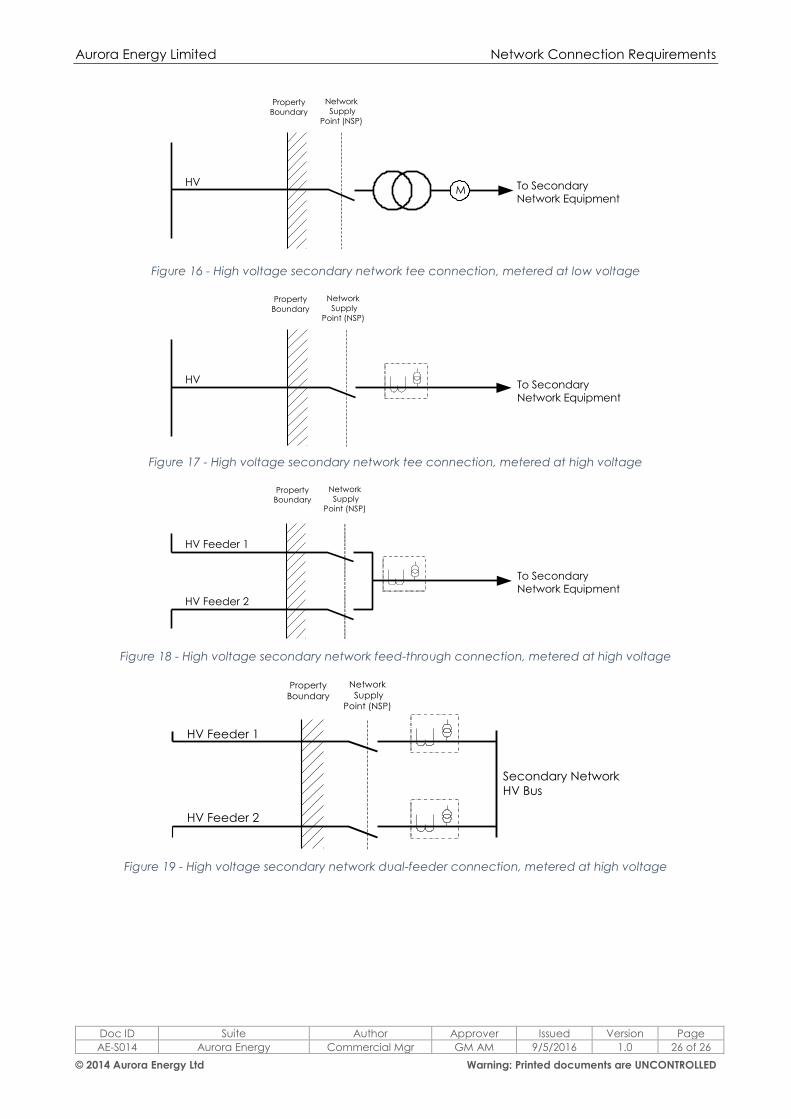
Aurora Energy Limited Network Connection Requirements
Doc ID Suite Author Approver Issued Version Page
AE-S014 Aurora Energy Commercial Mgr GM AM 9/5/2016 1.0 26 of 26
© 2014 Aurora Energy Ltd Warning: Printed documents are UNCONTROLLED
Figure 16 - High voltage secondary network tee connection, metered at low voltage
Figure 17 - High voltage secondary network tee connection, metered at high voltage
Figure 18 - High voltage secondary network feed-through connection, metered at high voltage
Figure 19 - High voltage secondary network dual-feeder connection, metered at high voltage
Network
Supply
Point (NSP)
Property
Boundary
MHV To Secondary
Network Equipment
HV To Secondary Network Equipment
Network
Supply
Point (NSP)
Property
Boundary
To Secondary
Network Equipment
HV Feeder 1
HV Feeder 2
Network
Supply
Point (NSP)
Property
Boundary
Secondary Network
HV Bus
HV Feeder 1
HV Feeder 2
Network
Supply
Point (NSP)
Property
Boundary