Embed Size (px)
Citation preview

Getting Started 10

Understanding the NetScaler
The Citrix NetScaler product is an application switch that performs application-specifictraffic analysis to intelligently distribute, optimize, and secure Layer 4-Layer 7 (L4–L7)network traffic for web applications. For example, a NetScaler bases load balancingdecisions on individual HTTP requests instead of on long-lived TCP connections, so thatthe failure or slowdown of a server is managed much more quickly and with lessdisruption to clients. The NetScaler feature set can be broadly categorized asconsisting of switching features, security and protection features, and server-farmoptimization features.
Switching FeaturesWhen deployed in front of application servers, a NetScaler ensures optimal distributionof traffic by the way in which it directs client requests. Administrators can segmentapplication traffic according to information in the body of an HTTP or TCP request, andon the basis of L4–L7 header information such as URL, application data type, or cookie.Numerous load balancing algorithms and extensive server health checks improveapplication availability by ensuring that client requests are directed to the appropriateservers.
Security and Protection FeaturesNetScaler security and protection features protect web applications from ApplicationLayer attacks. A NetScaler allows legitimate client requests and can block maliciousrequests. It provides built-in defenses against denial-of-service (DoS) attacks andsupports features that protect against legitimate surges in application traffic thatwould otherwise overwhelm the servers. An available built-in firewall protects webapplications from Application Layer attacks, including buffer overflow exploits, SQLinjection attempts, cross-site scripting attacks, and more. In addition, the firewallprovides identity theft protection by securing confidential corporate information andsensitive customer data.
Optimization FeaturesOptimization features offload resource-intensive operations, such as Secure SocketsLayer (SSL) processing, data compression, client keep-alive, TCP buffering, and thecaching of static and dynamic content from servers. This improves the performance ofthe servers in the server farm and therefore speeds up applications. A NetScalersupports several transparent TCP optimizations, which mitigate problems caused byhigh latency and congested network links, accelerating the delivery of applicationswhile requiring no configuration changes to clients or servers.
Understanding the NetScaler
2

Where Does a NetScaler Appliance Fit in theNetwork?
A NetScaler appliance resides between the clients and the servers, so that clientrequests and server responses pass through it. In a typical installation, virtual serversconfigured on the appliance provide connection points that clients use to access theapplications behind the appliance. In this case, the appliance owns public IP addressesthat are associated with its virtual servers, while the real servers are isolated in aprivate network. It is also possible to operate the appliance in a transparent mode asan L2 bridge or L3 router, or even to combine aspects of these and other modes.
Physical Deployment ModesA NetScaler appliance logically residing between clients and servers can be deployed ineither of two physical modes: inline and one-arm. In inline mode, multiple networkinterfaces are connected to different Ethernet segments, and the appliance is placedbetween the clients and the servers. The appliance has a separate network interface toeach client network and a separate network interface to each server network. Theappliance and the servers can exist on different subnets in this configuration. It ispossible for the servers to be in a public network and the clients to directly access theservers through the appliance, with the appliance transparently applying the L4-L7features. Usually, virtual servers (described later) are configured to provide anabstraction of the real servers. The following figure shows a typical inline deployment.
3

Figure 1. Inline Deployment
In one-arm mode, only one network interface of the appliance is connected to anEthernet segment. The appliance in this case does not isolate the client and serversides of the network, but provides access to applications through configured virtualservers. One-arm mode can simplify network changes needed for NetScaler installationin some environments.
For examples of inline (two-arm) and one-arm deployment, see "UnderstandingCommon Network Topologies."
Citrix NetScaler as an L2 DeviceA NetScaler functioning as an L2 device is said to operate in L2 mode. In L2 mode, theNetScaler forwards packets between network interfaces when all of the followingconditions are met:
w The packets are destined to another device's media access control (MAC) address.
w The destination MAC address is on a different network interface.
w The network interface is a member of the same virtual LAN (VLAN).
By default, all network interfaces are members of a pre-defined VLAN, VLAN 1. AddressResolution Protocol (ARP) requests and responses are forwarded to all network
Understanding the NetScaler
4

interfaces that are members of the same VLAN. To avoid bridging loops, L2 mode mustbe disabled if another L2 device is working in parallel with the NetScaler.
For information about how the L2 and L3 modes interact, see "Configuring Modes ofPacket Forwarding."
For information about configuring L2 mode, see "Enabling and Disabling Layer 2 Mode."
Citrix NetScaler as a Packet Forwarding DeviceA NetScaler appliance can function as a packet forwarding device, and this mode ofoperation is called L3 mode. With L3 mode enabled, the appliance forwards anyreceived unicast packets that are destined for an IP address that does not belong to theappliance, if there is a route to the destination. The appliance can also route packetsbetween VLANs.
In both modes of operation, L2 and L3, the appliance generally drops packets that arein:
w Multicast framesw Unknown protocol frames destined for an appliance's MAC address (non-IP and non-
ARP)w Spanning Tree protocol (unless BridgeBPDUs is ON)
For information about how the L2 and L3 modes interact, see "Configuring Modes ofPacket Forwarding."
For information about configuring the L3 mode, see "Enabling and Disabling Layer 3Mode."
How a NetScaler Communicates with Clientsand Servers
A NetScaler appliance is usually deployed in front of a server farm and functions as atransparent TCP proxy between clients and servers, without requiring any client-sideconfiguration. This basic mode of operation is called Request Switching technology andis the core of NetScaler functionality. Request Switching enables an appliance tomultiplex and offload the TCP connections, maintain persistent connections, andmanage traffic at the request (application layer) level. This is possible because theappliance can separate the HTTP request from the TCP connection on which therequest is delivered.
Depending on the configuration, an appliance might process the traffic beforeforwarding the request to a server. For example, if the client attempts to access asecure application on the server, the appliance might perform the necessary SSLprocessing before sending traffic to the server.
To facilitate efficient and secure access to server resources, an appliance uses a set ofIP addresses collectively known as NetScaler-owned IP addresses. To manage yournetwork traffic, you assign NetScaler-owned IP addresses to virtual entities that
5
become the building blocks of your configuration. For example, to configure loadbalancing, you create virtual servers to receive client requests and distribute them toservices, which are entities representing the applications on your servers.
Understanding NetScaler-Owned IP AddressesTo function as a proxy, a NetScaler appliance uses a variety of IP addresses. The keyNetScaler-owned IP addresses are:NetScaler IP (NSIP) address
The NSIP address is the IP address for management and general system access to theappliance itself, and for communication between appliances in a high availabilityconfiguration.
Mapped IP (MIP) addressA MIP address is used for server-side connections. It is not the IP address of theappliance. In most cases, when the appliance receives a packet, it replaces thesource IP address with a MIP address before sending the packet to the server. Withthe servers abstracted from the clients, the appliance manages connections moreefficiently.
Virtual server IP (VIP) addressA VIP address is the IP address associated with a virtual server. It is the public IPaddress to which clients connect. An appliance managing a wide range of traffic mayhave many VIPs configured.
Subnet IP (SNIP) addressA SNIP address is used in connection management and server monitoring. You canspecify multiple SNIP addresses for each subnet. SNIP addresses can be bound to aVLAN.
IP SetAn IP set is a set of IP addresses, which are configured on the appliance as SNIP . AnIP set is identified with a meaningful name that helps in identifying the usage of theIP addresses contained in it.
Net ProfileA net profile (or network profile) contains an IP address or an IP set. A net profilecan be bound to load balancing or content switching virtual servers, services, servicegroups, or monitors. During communication with physical servers or peers, theappliance uses the addresses specified in the profile as source IP addresses.
How Traffic Flows Are ManagedBecause a NetScaler appliance functions as a TCP proxy, it translates IP addressesbefore sending packets to a server. When you configure a virtual server, clients connectto a VIP address on the NetScaler instead of directly connecting to a server. Asdetermined by the settings on the virtual server, the appliance selects an appropriateserver and sends the client's request to that server. By default, the appliance uses aSNIP address to establish connections with the server, as shown in the following figure.
Understanding the NetScaler
6

Figure 2. Virtual Server Based Connections
In the absence of a virtual server, when an appliance receives a request, ittransparently forwards the request to the server. This is called the transparent mode ofoperation. When operating in transparent mode, an appliance translates the source IPaddresses of incoming client requests to the SNIP address but does not change thedestination IP address. For this mode to work, L2 or L3 mode has to be configuredappropriately.
For cases in which the servers need the actual client IP address, the appliance can beconfigured to modify the HTTP header by inserting the client IP address as anadditional field, or configured to use the client IP address instead of a SNIP address forconnections to the servers.
7

Traffic Management Building BlocksThe configuration of a NetScaler appliance is typically built up with a series of virtualentities that serve as building blocks for traffic management. The building blockapproach helps separate traffic flows. Virtual entities are abstractions, typicallyrepresenting IP addresses, ports, and protocol handlers for processing traffic. Clientsaccess applications and resources through these virtual entities. The most commonlyused entities are virtual servers and services. Virtual servers represent groups ofservers in a server farm or remote network, and services represent specific applicationson each server.
Most features and traffic settings are enabled through virtual entities. For example,you can configure an appliance to compress all server responses to a client that isconnected to the server farm through a particular virtual server. To configure theappliance for a particular environment, you need to identify the appropriate featuresand then choose the right mix of virtual entities to deliver them. Most features aredelivered through a cascade of virtual entities that are bound to each other. In thiscase, the virtual entities are like blocks being assembled into the final structure of adelivered application. You can add, remove, modify, bind, enable, and disable thevirtual entities to configure the features. The following figure shows the conceptscovered in this section.
Figure 3. How Traffic Management Building Blocks Work
A Simple Load Balancing ConfigurationIn the example shown in the following figure, the NetScaler appliance is configured tofunction as a load balancer. For this configuration, you need to configure virtual
Understanding the NetScaler
8

entities specific to load balancing and bind them in a specific order. As a load balancer,an appliance distributes client requests across several servers and thus optimizes theutilization of resources.
The basic building blocks of a typical load balancing configuration are services and loadbalancing virtual servers. The services represent the applications on the servers. Thevirtual servers abstract the servers by providing a single IP address to which the clientsconnect. To ensure that client requests are sent to a server, you need to bind eachservice to a virtual server. That is, you must create services for every server and bindthe services to a virtual server. Clients use the VIP address to connect to a NetScalerappliance. When the appliance receives client requests sent to the VIP address, itsends them to a server determined by the load balancing algorithm. Load balancinguses a virtual entity called a monitor to track whether a specific configured service(server plus application) is available to receive requests.
Figure 4. Load Balancing Virtual Server, Services, and Monitors
In addition to configuring the load balancing algorithm, you can configure severalparameters that affect the behavior and performance of the load balancingconfiguration. For example, you can configure the virtual server to maintainpersistence based on source IP address. The appliance then directs all requests fromany specific IP address to the same server.
Understanding Virtual ServersA virtual server is a named NetScaler entity that external clients can use to accessapplications hosted on the servers. It is represented by an alphanumeric name, virtual
9

IP (VIP) address, port, and protocol. The name of the virtual server is of only localsignificance and is designed to make the virtual server easier to identify. When a clientattempts to access applications on a server, it sends a request to the VIP instead of theIP address of the physical server. When the appliance receives a request at the VIPaddress, it terminates the connection at the virtual server and uses its own connectionwith the server on behalf of the client. The port and protocol settings of the virtualserver determine the applications that the virtual server represents. For example, aweb server can be represented by a virtual server and a service whose port andprotocol are set to 80 and HTTP, respectively. Multiple virtual servers can use the sameVIP address but different protocols and ports.
Virtual servers are points for delivering features. Most features, like compression,caching, and SSL offload, are normally enabled on a virtual server. When the appliancereceives a request at a VIP address, it chooses the appropriate virtual server by theport on which the request was received and its protocol. The appliance then processesthe request as appropriate for the features configured on the virtual server.
In most cases, virtual servers work in tandem with services. You can bind multipleservices to a virtual server. These services represent the applications running onphysical servers in a server farm. After the appliance processes requests received at aVIP address, it forwards them to the servers as determined by the load balancingalgorithm configured on the virtual server. The following figure illustrates theseconcepts.
Figure 5. Multiple Virtual Servers with a Single VIP Address
Understanding the NetScaler
10

The preceding figure shows a configuration consisting of two virtual servers with acommon VIP address but different ports and protocols. Each of the virtual servers hastwo services bound to it. The services s1 and s2 are bound to VS_HTTP and representthe HTTP applications on Server 1 and Server 2. The services s3 and s4 are bound toVS_SSL and represent the SSL applications on Server 2 and Server 3 (Server 2 providesboth HTTP and SSL applications). When the appliance receives an HTTP request at theVIP address, it processes the request as specified by the settings of VS_HTTP and sendsit to either Server 1 or Server 2. Similarly, when the appliance receives an HTTPSrequest at the VIP address, it processes it as specified by the settings of VS_SSL and itsends it to either Server 2 or Server 3.
Virtual servers are not always represented by specific IP addresses, port numbers, orprotocols. They can be represented by wildcards, in which case they are known aswildcard virtual servers. For example, when you configure a virtual server with awildcard instead of a VIP, but with a specific port number, the appliance intercepts andprocesses all traffic conforming to that protocol and destined for the predefined port.For virtual servers with wildcards instead of VIPs and port numbers, the applianceintercepts and processes all traffic conforming to the protocol.
Virtual servers can be grouped into the following categories:
Load balancing virtual serverReceives and redirects requests to an appropriate server. Choice of the appropriateserver is based on which of the various load balancing methods the user configures.
Cache redirection virtual serverRedirects client requests for dynamic content to origin servers, and requests forstatic content to cache servers. Cache redirection virtual servers often work inconjunction with load balancing virtual servers.
Content switching virtual serverDirects traffic to a server on the basis of the content that the client has requested.For example, you can create a content switching virtual server that directs all clientrequests for images to a server that serves images only. Content switching virtualservers often work in conjunction with load balancing virtual servers.
Virtual private network (VPN) virtual serverDecrypts tunneled traffic and sends it to intranet applications.
SSL virtual serverReceives and decrypts SSL traffic, and then redirects to an appropriate server.Choosing the appropriate server is similar to choosing a load balancing virtual server.
Understanding ServicesServices represent applications on a server. While services are normally combined withvirtual servers, in the absence of a virtual server, a service can still manageapplication-specific traffic. For example, you can create an HTTP service on aNetScaler appliance to represent a web server application. When the client attempts toaccess a web site hosted on the web server, the appliance intercepts the HTTP requestsand creates a transparent connection with the web server.
11

In service-only mode, an appliance functions as a proxy. It terminates clientconnections, uses a SNIP address to establish a connection to the server, and translatesthe destination IP addresses of incoming client requests to a SNIP address. Although theclients send requests directly to the IP address of the server, the server sees them ascoming from the SNIP address. The appliance translates the IP addresses, portnumbers, and sequence numbers.
A service is also a point for applying features. Consider the example of SSLacceleration. To use this feature, you must create an SSL service and bind an SSLcertificate to the service. When the appliance receives an HTTPS request, it decryptsthe traffic and sends it, in clear text, to the server. Only a limited set of features canbe configured in the service-only case.
Services use entities called monitors to track the health of applications. Every servicehas a default monitor, which is based on the service type, bound to it. As specified bythe settings configured on the monitor, the appliance sends probes to the application atregular intervals to determine its state. If the probes fail, the appliance marks theservice as down. In such cases, the appliance responds to client requests with anappropriate error message or re-routes the request as determined by the configuredload balancing policies.
Understanding Policies and ExpressionsA policy defines specific details of traffic filtering and management on a NetScaler. Itconsists of two parts: the expression and the action. The expression defines the typesof requests that the policy matches. The action tells the NetScaler what to do when arequest matches the expression. As an example, the expression might be to match aspecific URL pattern to a type of security attack, with the action being to drop or resetthe connection. Each policy has a priority, and the priorities determine the order inwhich the policies are evaluated.
When a NetScaler receives traffic, the appropriate policy list determines how toprocess the traffic. Each policy on the list contains one or more expressions, whichtogether define the criteria that a connection must meet to match the policy.
For all policy types except Rewrite policies, a NetScaler implements only the firstpolicy that a request matches, not any additional policies that it might also match. ForRewrite policies, the NetScaler evaluates the policies in order and, in the case ofmultiple matches, performs the associated actions in that order. Policy priority isimportant for getting the results you want.
Processing Order of FeaturesDepending on requirements, you can choose to configure multiple features. Forexample, you might choose to configure both compression and SSL offload. As a result,an outgoing packet might be compressed and then encrypted before being sent to theclient.
The following figure shows the L7 packet flow in the NetScaler.
Understanding the NetScaler
12

Figure 6. L7 Packet Flow Diagram
The following figure shows the DataStream packet flow in the NetScaler. DataStream issupported for MySQL and MS SQL databases. For information about the DataStreamfeature, see "DataStream."
13

Figure 7. DataStream Packet Flow Diagram
Understanding the NetScaler
14

Introduction to the Citrix NetScalerProduct Line
The Citrix NetScaler product line optimizes delivery of applications over the Internetand private networks, combining application-level security, optimization, and trafficmanagement into a single, integrated appliance. You install a NetScaler appliance inyour server room and route all connections to your managed servers through it. TheNetScaler features that you enable and the policies you set are then applied toincoming and outgoing traffic.
A NetScaler can be integrated into any network as a complement to existing loadbalancers, servers, caches, and firewalls. It requires no additional client or server sidesoftware, and can be configured using the NetScaler web-based GUI and CLIconfiguration utilities.
NetScaler appliances are available in a variety of hardware platforms that have a rangeof specifications, including multicore processors.
The NetScaler operating system is the base operating system for all NetScaler hardwareplatforms. The NetScaler operating system is available in three editions: Standard,Enterprise, and Platinum.
Citrix NetScaler Hardware PlatformsNetScaler hardware is available in a variety of platforms that have a range of hardwarespecifications, including multicore processors. All hardware platforms support somecombination of Fast Ethernet, Gigabit Ethernet, and 10 Gigabit Ethernet interfaces.
The following platforms are available for NetScaler 10.
w Citrix NetScaler MPX 5500
w Citrix NetScaler MPX 5550/5650
w Citrix NetScaler MPX 7500/9500
w Citrix NetScaler MPX 8200/8400/8600
w Citrix NetScaler MPX 9700/10500/12500/15500
w Citrix NetScaler MPX 11500/13500/14500/16500/18500/20500
w Citrix NetScaler MPX 15000
w Citrix NetScaler MPX 17000
w Citrix NetScaler MPX 17500/19500/21500
15

w Citrix NetScaler MPX 17550/19550/20550/21550
For more information about the hardware platform specifications, see "Introduction tothe Hardware Platforms."
The following tables list different editions of the NetScaler and the hardware platformson which they are available.
Table 1. Product Editions and MPX Hardware Platforms
Hardware
MPX5500
MPX5550/5650
MPX7500/9500
MPX8200/8400/8600
MPX15000
MPX17000
PlatinumEdition
Yes Yes Yes Yes Yes Yes
Enterprise Edition
Yes Yes Yes Yes Yes Yes
StandardEdition
Yes Yes Yes Yes Yes Yes
Table 2. Product Editions and MPX Hardware Platforms (contd.)
Hardware MPX9700/10500/12500/15500
MPX11500/13500/14500/16500/18500/20500
MPX17500/19500/21500
MPX17550/19550/20550/21550
PlatinumEdition
Yes Yes Yes Yes
EnterpriseEdition
Yes Yes Yes Yes
StandardEdition
Yes Yes Yes Yes
Citrix NetScaler EditionsThe NetScaler operating system is available in Standard, Enterprise, and Platinumeditions. The Enterprise and Standard editions have limited features available. Featurelicenses are required for all editions.
For instructions on how to obtain and install licenses, see "http://support.citrix.com/article/ctx121062."
The Citrix NetScaler editions are described as follows:
Introduction to the Citrix NetScaler Product Line
16

w Citrix NetScaler, Standard Edition. Provides small and medium enterprises withcomprehensive Layer 4- Layer 7 (L4-L7) traffic management, enabling increased webapplication availability.
w Citrix NetScaler, Enterprise Edition. Provides web application acceleration andadvanced L4-L7 traffic management, enabling enterprises to increase webapplication performance and availability and reduce datacenter costs.
w Citrix NetScaler, Platinum Edition. Provides a web application delivery solution thatreduces data center costs and accelerates application performance, with end-to-end visibility of application performance, and provides advanced applicationsecurity.
The following table summarizes the features supported by each edition in the CitrixNetScaler product line:
Table 3. Citrix NetScaler Application Delivery Product Line Features
Key Features PlatinumEdition
EnterpriseEdition
StandardEdition
Application availability
Layer 4 load balancing Yes Yes Yes
Layer 7 content switching Yes Yes Yes
AppExpert rate controls Yes Yes Yes
IPv6 support Yes Yes Yes
Global server load balancing (GSLB) Yes Yes Optional
Dynamic routing protocols Yes Yes No
Surge protection Yes Yes No
Priority queuing Yes Yes No
Application acceleration
Client and server TCP optimizations Yes Yes Yes
Citrix AppCompress for HTTP Yes Yes Optional
Citrix AppCache Yes Optional No
Citrix Branch Repeater client Yes No No
Application security
Layer 4 DoS defenses Yes Yes Yes
Layer 7 content filtering Yes Yes Yes
17

Key Features PlatinumEdition
EnterpriseEdition
StandardEdition
HTTP/URL Rewrite Yes Yes Yes
Access Gateway, EE SSL VPN Yes Yes Yes
Layer 7 DoS Defenses Yes Yes No
AAA security Yes Yes No
Application firewall with XML security Yes Optional No
Simple manageability
AppExpert visual policy builder Yes Yes Yes
AppExpert service callouts Yes Yes Yes
AppExpert templates Yes Yes Yes
Role-based administration Yes Yes Yes
Configuration wizards Yes Yes Yes
Citrix Command Center Yes Yes No
Citrix EdgeSight for NetScaler Yes Optional No
Web 2.0 optimization
Rich Internet application support Yes Yes Yes
Advanced server offload Yes Yes No
Lower total cost of ownership (TCO)
TCP buffering Yes Yes Yes
TCP multiplexing Yes Yes Yes
SSL offload and acceleration Yes Yes Yes
Cache redirection Yes Yes No
Citrix EasyCall Yes No No
Note: While we have taken care to ensure absolute accuracy when compiling thisinformation, it might change. For the latest information, see Citrix Support at "http://www.citrix.com."
Introduction to the Citrix NetScaler Product Line
18
Supported Releases on NetScalerHardware
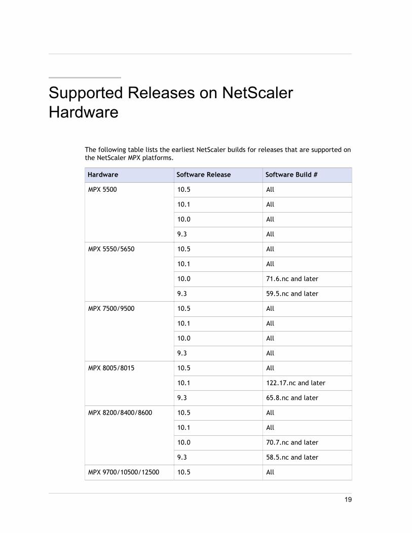
The following table lists the earliest NetScaler builds for releases that are supported onthe NetScaler MPX platforms.
Hardware Software Release Software Build #
MPX 5500 10.5 All
10.1 All
10.0 All
9.3 All
MPX 5550/5650 10.5 All
10.1 All
10.0 71.6.nc and later
9.3 59.5.nc and later
MPX 7500/9500 10.5 All
10.1 All
10.0 All
9.3 All
MPX 8005/8015 10.5 All
10.1 122.17.nc and later
9.3 65.8.nc and later
MPX 8200/8400/8600 10.5 All
10.1 All
10.0 70.7.nc and later
9.3 58.5.nc and later
MPX 9700/10500/12500 10.5 All
19
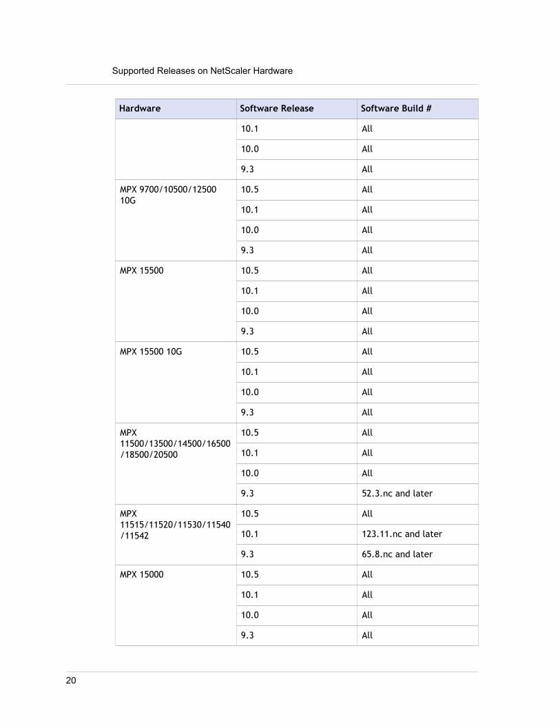
Hardware Software Release Software Build #
10.1 All
10.0 All
9.3 All
MPX 9700/10500/1250010G
10.5 All
10.1 All
10.0 All
9.3 All
MPX 15500 10.5 All
10.1 All
10.0 All
9.3 All
MPX 15500 10G 10.5 All
10.1 All
10.0 All
9.3 All
MPX11500/13500/14500/16500/18500/20500
10.5 All
10.1 All
10.0 All
9.3 52.3.nc and later
MPX11515/11520/11530/11540/11542
10.5 All
10.1 123.11.nc and later
9.3 65.8.nc and later
MPX 15000 10.5 All
10.1 All
10.0 All
9.3 All
Supported Releases on NetScaler Hardware
20

Hardware Software Release Software Build #
MPX 17000 10.5 All
10.1 All
10.0 All
9.3 All
MPX 17500/19500/21500 10.5 All
10.1 All
10.0 All
9.3 All
MPX17550/19550/20550/21550
10.5 All
10.1 All
10.0 All
9.3 53.5.nc and later
MPX22040/22060/22080/22100/22120
10.5 51.10.nc and later
10.1 123.11.nc and later
9.3 65.8.nc and later
MPX 24100/24150 10.5 51.10.nc and later
10.1 129.11.nc and later
21

Installing the NetScaler Hardware
Before installing a NetScaler appliance, review the pre-installation checklist. ANetScaler is typically mounted in a rack, and all models ship with rack-rail hardware.All models except the 7000 support small form factor pluggable SFP, XFP, or SFP+transceivers. After mounting the appliance and installing the transceivers, connect theNetScaler to your network. Use a console cable to connect the NetScaler to a personalcomputer so that you can perform an initial configuration. After connecting everythingelse, connect the NetScaler to a power source.
Unpacking the ApplianceThe hardware accessories for your particular appliance, such as cables, adapters, andrail kit, vary depending on the hardware platform you ordered. Unpack the box thatcontains your new appliance on a sturdy table with plenty of space and inspect thecontents.
Use the following list to verify that you received everything that should have beenincluded in the box.
w The appliance you ordered
w One RJ-45 to DB-9 adapter
w One 6 ft RJ-45/DB-9 cable
w Two power cables
w One fiber patch cable
w The following list specifies the number of power cables included for each appliancemodel:
• One power cable for the MPX 5500, MPX 5550/5650, MPX 7500/9500, and MPX8200/8400/8600/8800 appliances
• Two power cables for the MPX 15000, MPX 17000, MPX 9700/10500/12500/15500,MPX 11500/13500/14500/16500/18500/20500, MPX 17500/19500/21500, and MPX25100T/25160T, and MPX 17550/19550/20550/21550 appliances
Note: For Brazilian customers, Citrix does not ship a power cable. Use a cable thatconforms to the ABNT NBR 14136:2002 standard.
w One standard 4-post rail kit
Note: If the kit that you received does not fit your rack, contact your Citrix salesrepresentative to order the appropriate kit.
Installing the NetScaler Hardware
22

In addition to the items included in the box with your new appliance, you will need thefollowing items to complete the installation and initial configuration process.
w Ethernet cables for each additional Ethernet port that you will connect to yournetwork
w One available Ethernet port on your network switch or hub for each NetScalerEthernet port you want to connect to your network
Note: Transceiver modules are sold separately. Contact your Citrix salesrepresentative to order transceiver modules for your appliance. Only transceiverssupplied by Citrix are supported on the appliance.
w A computer to serve as a management workstation
Rack Mounting the ApplianceMost appliances can be installed in standard server racks that conform to EIA-310-Dspecification. The appliances ship with a set of rails, which you must install before youmount the appliance. The only tools that you need for installing an appliance are aPhillips screwdriver and a flathead screwdriver.
Caution: If you are installing the appliance as the only unit in the rack, mount it atthe bottom. If the rack contains other units, make sure that the heaviest unit is at thebottom. If the rack has stabilizing devices available, install them before mounting theappliance.
The following table lists the different hardware platforms and the rack units requiredfor each platform.
Table 1. Height Requirements For Each Platform
Platform Number of rack units
MPX 5500 One rack unit
MPX 5550/5650 One rack unit
MPX 7500/9500 One rack unit
MPX 8200/8400/8600/8800 One rack unit
MPX 9700/10500/12500/15500 Two rack units
MPX 15000, MPX 17000 Two rack units
23

MPX11500/13500/14500/16500/18500/20500
Two rack units
MPX 17500/19500/21500 Two rack units
MPX 17550/19550/20550/21550 Two rack units
Each appliance ships with a mounting rail kit that contains two rail assemblies, one forthe left side and the other for the right side of the appliance, and screws to attach therails. An assembly consists of an inner rail and a rack rail. The supplied rail kit is 28inches long (38 inches extended). Contact your Citrix sales representative to order a23-inch (33 inches extended) rail kit.
Note: The same rail kit is used for both square-hole and round-hole racks. See"Installing the Rail Assembly to the Rack" for specific instructions for threaded, round-hole racks.
To mount the appliance, you must first install the rails and then install the appliance inthe rack.
Perform the following tasks to mount the appliance:
w Remove the inner rails from the rail assembly.
w Attach the inner rails to the appliance.
w Install the rack rails on the rack.
w Install the appliance in the rack.
The appliance is shipped with rack-rail hardware. This hardware consists of includingtwo inner rails that you attach to the appliance, one on each side, and a rack-railassembly that you attach to the rack. The following figure illustrates The followingfigure shows the steps involved in mounting the Citrix NetScaler how to mount theappliance to a rack.
To remove the inner rails from the rail assembly1. Place the rail assembly on a flat surface.
2. Slide out the inner rail toward the front of the assembly.
3. Depress the latch until the inner rail comes all the way out of the rail assembly.
4. Repeat steps 1 through 3 to remove the second inner rail.
To attach the inner rails to the appliance1. Position the right inner rail behind the handle on the right side of the appliance.
Installing the NetScaler Hardware
24

2. Align the holes on the rail with the corresponding holes on the side of theappliance.
3. Attach the rail to the appliance with the provided screws: 4 per side for a 1Uappliance and 5 per side for a 2U appliance, as shown in the following figure.
Figure 1. Attaching inner rails
4. Repeat steps 1 through 3 to install the left inner rail on the other side of theappliance.
To install the rack rails on the rack1. If you have a round-hole, threaded rack, skip to step 3.
2. Install square nut retainers into the front post and back post of the rack as shownin the following figures. Before inserting a screw, be sure to align the square nutwith the correct hole for your 1U or 2U appliance. The three holes are not evenlyspaced.
Figure 2. Installing Retainers into the Front Rack Posts
Figure 3. Installing Retainers into the Rear Rack Posts
25

3. Install the adjustable rail assembly into the rack as shown in the following figures.Use a screw to lock the rear rail flange into the rack. With the screw securing therail in place, you can optionally remove the latching spring.
Figure 4. Installing the Rail Assembly to the Rack
To install the appliance in the rack1. Align the inner rails, attached to the appliance, with the rack rails.
2. Slide the appliance into the rack rails, keeping the pressure even on both sides.
3. Verify that the appliance is locked in place by pulling it all the way out from therack.
Installing the NetScaler Hardware
26
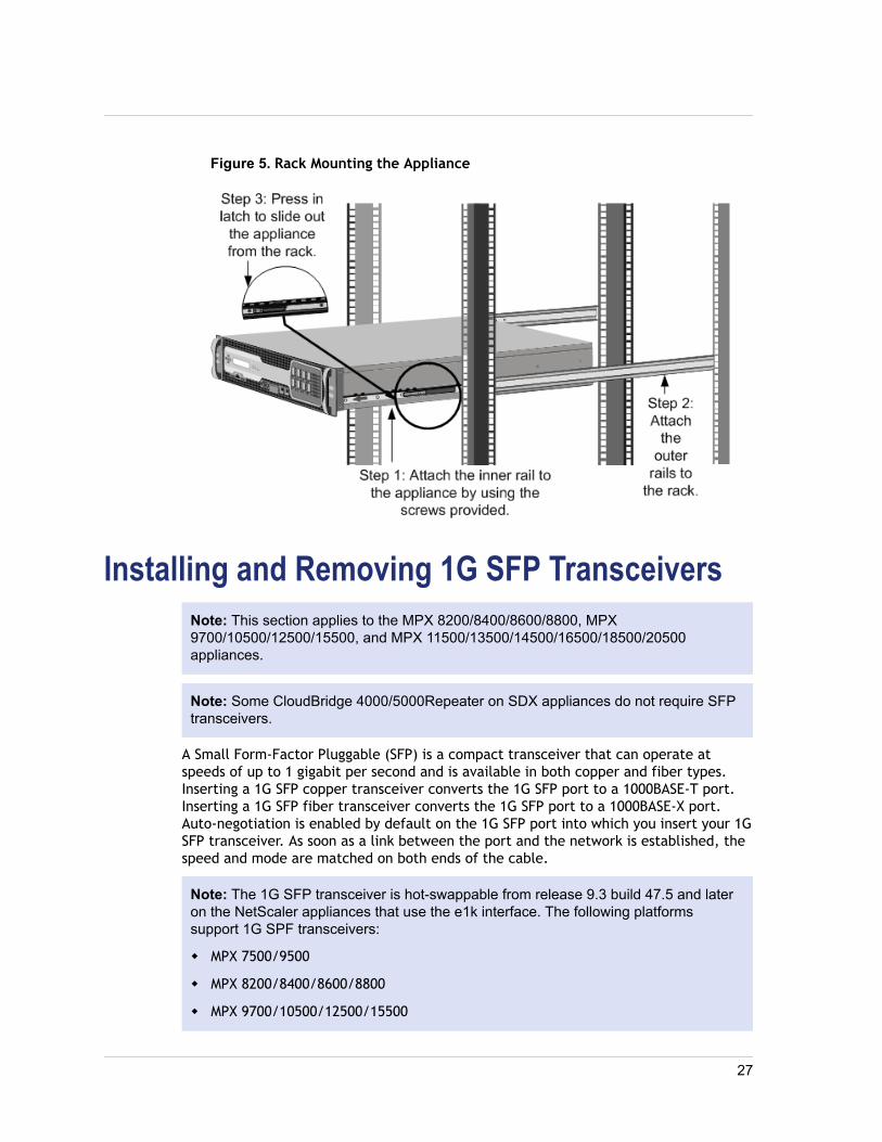
Figure 5. Rack Mounting the Appliance
Installing and Removing 1G SFP TransceiversNote: This section applies to the MPX 8200/8400/8600/8800, MPX9700/10500/12500/15500, and MPX 11500/13500/14500/16500/18500/20500appliances.
Note: Some CloudBridge 4000/5000Repeater on SDX appliances do not require SFPtransceivers.
A Small Form-Factor Pluggable (SFP) is a compact transceiver that can operate atspeeds of up to 1 gigabit per second and is available in both copper and fiber types.Inserting a 1G SFP copper transceiver converts the 1G SFP port to a 1000BASE-T port.Inserting a 1G SFP fiber transceiver converts the 1G SFP port to a 1000BASE-X port.Auto-negotiation is enabled by default on the 1G SFP port into which you insert your 1GSFP transceiver. As soon as a link between the port and the network is established, thespeed and mode are matched on both ends of the cable.
Note: The 1G SFP transceiver is hot-swappable from release 9.3 build 47.5 and lateron the NetScaler appliances that use the e1k interface. The following platformssupport 1G SPF transceivers:
w MPX 7500/9500
w MPX 8200/8400/8600/8800
w MPX 9700/10500/12500/15500
27

w MPX 11500/13500/14500/16500/18500/20500
Caution: NetScalerCloudBridge 4000/5000Repeater on SDX appliances do notsupport 1G SFP transceivers from vendors other than Citrix Systems. Attempting toinstall third-party 1G SFP transceivers on your NetScalerCloudBridge4000/5000Repeater on SDX appliance voids the warranty.
Insert 1G SFP transceivers into the 1G SFP ports on the front panel of the appliance.Frequent installation and removal of transceivers shortens their life span. Follow theremoval procedure carefully to avoid damaging the 1G SFP transceiver or theappliance.
Caution: Do not install the transceivers with the cables attached. Doing so candamage the cable, the connector, or the optical interface of the transceiver.
To install a 1G SFP transceiver1. Remove the 1G SFP transceiver carefully from its box.
Danger: Do not look directly into fiber optic transceivers or cables. They emitlaser beams that can damage your eyes.
2. Align the 1G SFP transceiver to the front of the 1G SFP transceiver port on thefront panel of the appliance, as shown in the following figure.
Note: The illustration in the following figures might not represent your actualappliance.
Figure 6. Installing a 1G SFP transceiver
Installing the NetScaler Hardware
28

3. Hold the 1G SFP transceiver between your thumb and index finger and insert it intothe 1G SFP transceiver port, pressing it in until you hear the transceiver snap intoplace.
4. Lock the transceiver.
5. Verify that the LED is green and blinks twice, which indicates that the transceiveris functioning correctly.
6. If you are using a fiber 1G SFP transceiver, do not remove the dust caps attachedto the transceiver and the cable until you are ready to insert the cable.
To remove a 1G SFP transceiver1. Disconnect the cable from the 1G SFP transceiver. If you are using a fiber optic
cable, replace the dust cap on the cable before putting it away.
Danger: Do not look directly into fiber optic transceivers or cables. They emitlaser beams that can damage your eyes.
2. Unlock the 1G SFP transceiver.
3. Hold the 1G SFP transceiver between your thumb and index finger and slowly pullit out of the port.
4. If you are removing a fiber 1G SFP transceiver, replace the dust cap before puttingit away.
5. Put the 1G SFP transceiver into its original box or another appropriate container.
Installing and Removing XFP and 10G SFP+Transceivers
Note: This section applies to the MPX 8200/8400/8600/8800, MPX9700/10500/12500/15500, MPX 15000, MPX 17000, MPX11500/13500/14500/16500/18500/20500, MPX 17500/19500/21500, and MPX17550/19550/20550/21550 appliances.
Note: Some CloudBridge 4000/5000Repeater on SDX appliances do not require SFP+transceivers.
A 10-Gigabit Small Form-Factor Pluggable (XFP or SFP+) is a compact opticaltransceiver that can operate at speeds of up to 10 gigabits per second. The MPX 15000and MPX 17000 appliances use XFP transceivers and the MPX 8200/8400/8600/8800,MPX 9700/10500/12500/15500, MPX 11500/13500/14500/16500/18500/20500, MPX17500/19500/21500, and MPX 17550/19550/20550/21550 appliances use 10G SFP+transceivers. Autonegotiation is enabled by default on the XFP/10G SFP+ ports intowhich you insert your XFP/10G SFP+ transceiver. As soon as a link between the port and
29

the network is established, the mode is matched on both ends of the cable and for 10GSFP+ transceivers, the speed is also autonegotiated.
Note: An XFP transceiver is not hot-swappable on the NetScaler appliances. Youmust restart a NetScaler appliance after you insert an XFP transceiver.However, the 10G SFP+ transceiver is hot-swappable from release 9.3 build 57.5 andlater on the NetScaler appliances that use the ixgbe (ix) interface. The followingplatforms support 10G SPF+ transceivers:
w MPX 8200/8400/8600/8800
w MPX 9700/10500/12500/15500 10G and 10G FIPS
w MPX 11500/13500/14500/16500/18500/20500
w MPX 17500/19500/21500
w MPX 17550/19550/20550/21550
The following platforms support XFP transceivers:
w MPX 15000
w MPX 17000
Caution: NetScalerCloudBridge 4000/5000Repeater on SDX appliances do notsupport XFP/10G SFP+ transceivers provided by vendors other than Citrix Systems.Attempting to install third-party XFP/10G SFP+ transceivers on yourNetScalerCloudBridge 4000/5000Repeater on SDX appliance voids the warranty.
Insert the XFP/10G SFP+ transceivers into the XFP/10G SFP+ ports on the front panel ofthe appliance. Frequent installation and removal of transceivers shortens their lifespan. Follow the removal procedure carefully to avoid damaging the transceiver or theappliance.
Caution: Do not install the transceivers with the cables attached. Doing so candamage the cable, the connector, or the optical interface of the transceiver.
To install an XFP/a 10G SFP+ transceiver1. Remove the XFP/10G SFP+ transceiver carefully from its box.
Danger: Do not look directly into fiber optic transceivers and cables. Theyemit laser beams that can damage your eyes.
2. Align the XFP/10G SFP+ transceiver to the front of the XFP/10G SFP+ transceiverport on the front panel of the appliance.
Installing the NetScaler Hardware
30

3. Hold the XFP/10G SFP+ transceiver between your thumb and index finger andinsert it into the XFP/10G SFP+ transceiver port, pressing it in until you hear thetransceiver snap into place.
4. Move the locking hinge to the DOWN position as shown in the following figure.
Figure 7. Locking an XFP transceiver
5. Verify that the LED is green and blinks twice, which indicates that the transceiveris functioning correctly.
6. Do not remove the dust caps attached to the transceiver and cable until you areready to insert the cable.
To remove an XFP/a 10G SFP+ transceiver1. Disconnect the cable from the XFP/10G SFP+ transceiver. Replace the dust cap on
the cable before putting it away.
Danger: Do not look directly into fiber optic transceivers or cables. They emitlaser beams that can damage your eyes.
2. Unlock the XFP/10G SFP+ transceiver by moving the locking hinge to the UPposition.
3. Hold the XFP/10G SFP+ transceiver between your thumb and index finger andslowly pull it out of the port.
4. Replace the dust cap on the transceiver before putting it away.
5. Put the XFP/10G SFP+ transceiver into its original box or another appropriatecontainer.
31

Connecting the CablesWhen the appliance is securely mounted on the rack, you are ready to connect thecables. Ethernet cables and the optional console cable are connected first. Connect thepower cable last.
Danger: Before installing or repairing the appliance, remove all jewelry and othermetal objects that might come in contact with power sources or wires. When you touchboth a live power source or wire and ground, any metal objects can heat up rapidlyand cause burns, set clothing on fire, or fuse the metal object to an exposed terminal.
Connecting the Ethernet CablesConnecting theAppliance to the Network
Ethernet cables connect your appliance to the network. The type of cable you needdepends on the type of port used to connect to the network. Use a category 5e orcategory 6 Ethernet cable with a standard RJ-45 connector on a 10/100/1000BASE-Tport or 1G SFP copper transceiver. Use a fiber optic cable with an LC duplex connectorwith a 1G SFP fiber transceiver, or 10G SFP+, or XFP transceiver. The type of connectorat the other end of the fiber optic cable depends on the port of the device that you areconnecting to.
To connect an Ethernet cable to a 10/100/1000BASE-T portor 1G SFP copper transceiver1. Insert the RJ-45 connector on one end of your Ethernet cable into an appropriate
port on the front panel of the appliance, as shown in the following figure.
Figure 8. Inserting an Ethernet cable
2. Insert the RJ-45 connector on the other end into the target device, such as arouter or switch.
3. Verify that the LED glows amber when the connection is established.
Installing the NetScaler Hardware
32

To connect the Ethernet cable to a 1G SFP fiber, or 10G SFP+, or XFP transceiver1. Remove the dust caps from the transceiver and cable.
2. Insert the LC connector on one end of the fiber optic cable into the appropriateport on the front panel of the appliance.
3. Insert the connector on the other end into the target device, such as a router orswitch.
4. Verify that the LED glows amber when the connection is established.
Connecting the Console CableYou can use the console cable to connect your appliance to a computer or terminal,from which you can configure the appliance. Alternatively, you can use a computerconnected to the network. Before connecting the console cable, configure thecomputer or terminal to support VT100 terminal emulation, 9600 baud, 8 data bits, 1stop bit, parity, and flow control set to NONE. Then connect one end of the consolecable to the RS232 serial port on the appliance and the other end to the computer orterminal.
To connect the console cable to a computer or terminal1. Insert the DB-9 connector at the end of the cable into the console port that is
located on the front panel of the appliance, as shown in the following figure.
Figure 9. Inserting a console cable
Note: To use a cable with an RJ-45 converter, insert the optional converterprovided into the console port and attach the cable to it.
2. Insert the RJ-45 connector at the other end of the cable into the serial port of thecomputer or terminal.
Connecting the Power CableConnecting theAppliance to a Power Source
An MPX 5500, MPX 5550/5650, MPX 7500/9500, and MPX 8200/8400/8600/8800appliance has one power cable. All the other appliances come with two power cables,
33
but they can also operate if only one power cable is connected. A separate groundcable is not required, because the three-prong plug provides grounding.
The CloudBridge 4000/5000Repeater on SDX appliance has two power supplies, withone serving as a backup. A separate ground cable is not required, because the three-prong plug provides grounding. Power up the appliance by installing one or both powercords.
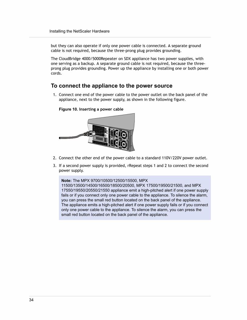
To connect the appliance to the power source1. Connect one end of the power cable to the power outlet on the back panel of the
appliance, next to the power supply, as shown in the following figure.
Figure 10. Inserting a power cable
2. Connect the other end of the power cable to a standard 110V/220V power outlet.
3. If a second power supply is provided, rRepeat steps 1 and 2 to connect the secondpower supply.
Note: The MPX 9700/10500/12500/15500, MPX11500/13500/14500/16500/18500/20500, MPX 17500/19500/21500, and MPX17550/19550/20550/21550 appliance emit a high-pitched alert if one power supplyfails or if you connect only one power cable to the appliance. To silence the alarm,you can press the small red button located on the back panel of the appliance.The appliance emits a high-pitched alert if one power supply fails or if you connectonly one power cable to the appliance. To silence the alarm, you can press thesmall red button located on the back panel of the appliance.
Installing the NetScaler Hardware
34

Accessing a Citrix NetScaler
A NetScaler appliance has both a command line interface (CLI) and a graphical userinterface (GUI). The GUI includes a configuration utility for configuring the applianceand a statistical utility, called Dashboard. For initial access, all appliances ship with thedefault NetScaler IP address (NSIP) of 192.168.100.1 and default subnet mask of255.255.0.0. You can assign a new NSIP and an associated subnet mask during initialconfiguration.
If you encounter an IP address conflict when deploying multiple NetScaler units, checkfor the following possible causes:
w Did you select an NSIP that is an IP address already assigned to another device onyour network?
w Did you assign the same NSIP to multiple NetScaler appliances?
w The NSIP is reachable on all physical ports. The ports on a NetScaler are host ports,not switch ports.
The following table summarizes the available access methods.
Table 1. Methods for Accessing a NetScaler appliance
Access Method Port Default IP AddressRequired? (Y/N)
CLI Console N
CLI and GUI Ethernet Y
Using the Command Line InterfaceYou can access the CLI either locally, by connecting a workstation to the console port,or remotely, by connecting through secure shell (SSH) from any workstation on thesame network.
Logging on to the Command Line Interface throughthe Console Port
The appliance has a console port for connecting to a computer workstation. To log onto the appliance, you need a serial crossover cable and a workstation with a terminalemulation program.
35

To log on to the CLI through the console port1. Connect the console port to a serial port on the workstation, as described in
"Connecting the Console Cable".
2. On the workstation, start HyperTerminal or any other terminal emulation program.If the logon prompt does not appear, you may need to press ENTER one or moretimes to display it.
3. Log on by using the administrator credentials.The command prompt (>) appears on the workstation monitor.
Logging on to the Command Line Interface by usingSSH
The SSH protocol is the preferred remote access method for accessing an applianceremotely from any workstation on the same network. You can use either SSH version 1(SSH1) or SSH version 2 (SSH2.)
If you do not have a working SSH client, you can download and install any of thefollowing SSH client programs:
w PuTTY
Open Source software supported on multiple platforms. Available at:
"http://www.chiark.greenend.org.uk/~sgtatham/putty/"
w Vandyke Software SecureCRT
Commercial software supported on the Windows platform. Available at:
"http://www.vandyke.com/products/securecrt/"
These programs have been tested by the Citrix NetScaler team, which has verified thatthey work correctly with a NetScaler appliance. Other programs may also workcorrectly, but have not been tested.
To verify that the SSH client is installed properly, use it to connect to any device onyour network that accepts SSH connections.
To log on to a NetScaler by using an SSH client1. On your workstation, start the SSH client.
2. For initial configuration, use the default NetScaler IP address (NSIP), which is192.168.100.1. For subsequent access, use the NSIP that was assigned during initialconfiguration. Select either SSH1 or SSH2 as the protocol.
3. Log on by using the administrator credentials. For example:
login as: nsrootUsing keyboard-interactive authentication.Password:
Accessing a Citrix NetScaler
36

Last login: Tue Jun 16 10:37:28 2009 from 10.102.29.9
Done>
Using the Graphical User InterfaceImportant: A certificate-key pair is required for HTTPS access to the NetScalerconfiguration utility. On a NetScaler ADC, a certificate-key pair is automatically boundto the internal services. On an MPX or SDX appliance, the default key size is 1024bytes, and on a VPX instance, the default key size is 512 bytes. However, mostbrowsers today do not accept a key that is less than 1024 bytes. As a result, HTTPSaccess to the VPX configuration utility is blocked.Additionally, if a license is not present on an MPX appliance when it starts, and youadd a license later and restart the appliance, you might lose the certificate binding.
Citrix recommends that you install a certificate-key pair of at least 1024 bytes on aNetScaler ADC for HTTPS access to the configuration utility, and that you install anappropriate license before starting the ADC.
The graphical user interface includes a configuration utility and a statistical utility,called Dashboard, either of which you access through a workstation connected to anEthernet port on the appliance. If your computer does not have a supported Java plug-in installed, the utility prompts you to download and install the plug-in the first timeyou log on. If automatic installation fails, you can install the plug-in separately beforeyou attempt to log on to the configuration utility or Dashboard.
The system requirements for the workstation running the GUI are as follows:
w For Windows-based workstations, a Pentium 166 MHz or faster processor with atleast 48 MB of RAM is recommended for applets running in a browser using a Javaplug-in product. You should have 40 MB free disk space before installing the plug-in.
w For Linux-based workstations, a Pentium platform running Linux kernel v2.2.12 orabove, and glibc version 2.12-11 or later. A minimum of 32 MB RAM is required, and48 MB RAM is recommended. The workstation should support 16-bit color mode, KDEand KWM window managers used in conjunction, with displays set to local hosts.
w For Solaris-based workstations, a Sun running either Solaris 2.6, Solaris 7, or Solaris8, and the Java 2 Runtime Environment, Standard Edition, version 1.6 or later.
Your workstation must have a supported web browser and version 1.6 or above of theJava applet plug-in installed to access the configuration utility and Dashboard.
The following browsers are supported.
37

Using the Configuration UtilityOnce you log on to the configuration utility, you can configure the appliance through agraphical interface that includes context-sensitive help.
If your computer does not have a supported Java plug-in installed, the first time youlog on to the appliance, the configuration utility will prompt you to download andinstall the plug-in.
Note: Prior to installing the Java 2 Runtime Environment, ensure that you haveinstalled the full set of required operating system patches needed for the current Javarelease.
To log on to the configuration utility
1. Open your web browser and enter the NetScaler IP (NSIP) as an HTTP address. Ifyou have not yet set up the initial configuration, enter the default NSIP (http://192.168.100.1).The Citrix Logon page appears.
Note: If you have two NetScaler appliances in a high availability setup, make surethat you do not access the GUI by entering the IP address of the secondaryNetScaler. If you do so and use the GUI to configure the secondary NetScaler,your configuration changes will not be applied to the primary NetScaler.
2. In the User Name text box, type nsroot.3. In the Password text box, type the administrative password you assigned to the
nsroot account during initial configuration and click Login.The Configuration Utility page appears.
Note: If your workstation does not already have a supported version of the Javaruntime plug-in installed, the NetScaler prompts you to download the Java Plug-in.After the download is complete, the configuration utility page appears.If you need to access the online help, select Help from the Help menu at the topright corner.
4. In the Start in list, click Configuration, and then click Login.The Configuration Utility page appears.
Note: If your workstation does not already have a supported version of the Javaruntime plug-in installed, the NetScaler prompts you to download the Java Plug-in.After the download is complete, the configuration utility page appears.If you need to access the online help, select Help from the Help menu at the topright corner.
Accessing a Citrix NetScaler
38

Using the Statistical UtilityDashboard, the statistical utility, is a browser-based application that displays chartsand tables on which you can monitor the performance of a NetScaler.
To log on to Dashboard
1. Open your web browser and enter the NSIP as an HTTP address (http://<NSIP>).The Citrix Logon page appears.
2. In the User Name text box, type nsroot.3. In the Password text box, type the administrative password you assigned to the
nsroot account during initial configuration.
4. In the Start in list, click Dashboard, and then click Login.
Installing the Java Runtime Plug-inIf automatic installation of the Java plug-in fails, you can install the plug-in separatelybefore you attempt to log on to the configuration utility.
Note: Before installing the Java 2 Runtime Environment, make sure that you haveinstalled the full set of required operating system patches needed for the current Javarelease.
To install the Java runtime plug-in on your workstation
1. In your web browser, enter the NSIP and port number of your appliance: http://<NSIP>:80The Java plug-in icon appears.
2. Click the Java plug-in icon and follow the screen prompts to copy the plug-ininstaller to your workstation hard disk. The Java plug-in setup icon (for example,j2re-1.6.0) appears on your computer at the location you specified.
3. Double-click the plug-in setup icon, and follow the screen prompts to install theplug-in.
4. Return to your web browser and click the Java plug-in icon a second time todisplay the GUI logon screen.
39

Configuring a NetScaler for the First Time
Your new NetScaler is preconfigured with a default IP address (the NSIP) and associatedsubnet mask for management access. The default NSIP is 192.168.100.1 and the subnetmask (netmask) is 255.255.0.0. You can change these values to fit the addressingscheme for your network. For your initial configuration, you must also specify at leastone SNIP or MIP. Before saving your new configuration, you should change theadministrator password.
You can perform the initial configuration of your appliance by using any of thefollowing interfaces:
w LCD Keypad
w Command Line Interface
w Configuration Utility
w XML API
If you are setting up two NetScaler appliances as a high availability pair, you configureone as primary and the other as secondary.
The configuration procedure for a FIPS appliance is slightly different from theprocedure for a NetScaler MPX appliance or a NetScaler virtual appliance.
Using the LCD KeypadWhen you first install the appliance, you can configure the initial settings by using theLCD keypad on the front panel of the appliance. The keypad interacts with the LCDdisplay module, which is also on the front panel of these appliances.
Note: You can use the LCD keypad for initial configuration on a new appliance with thedefault configuration. The configuration file (ns.conf) should contain the followingcommand and default values.
set ns config -IPAddress 192.168.100.1 -netmask 255.255.0.0
The functions of the different keys are explained in the following table.
Table 1. LCD Key Functions
Key Function
< Moves the cursor one digit to the left.
> Moves the cursor one digit to the right.
Configuring a NetScaler for the First Time
40

Key Function
^ Increments the digit under the cursor.
v Decrements the digit under the cursor.
. Processes the information, or terminates the configuration, if noneof the values are changed. This key is also known as the ENTER key.
To perform the initial configuration by using the LCD keypad press the "<" key.
You are prompted to enter the subnet mask, NetScaler IP address (NSIP), and gatewayin that order respectively. The subnet mask is associated with both the NSIP anddefault gateway IP address. The NSIP is the IPv4 address of the NetScaler appliance.The default gateway is the IPv4 address for the router, which will handle external IPtraffic that the NetScaler cannot otherwise route. The NSIP and the default gatewayshould be on the same subnet.
If you enter a valid value for the subnet mask, such as 255.255.255.224, you areprompted to enter the IP address. Similarly, if you enter a valid value for the IPaddress, you are prompted to enter the gateway address. If the value you entered isinvalid, the following error message appears for three seconds, where xxx.xxx.xxx.xxxis the IP address you entered, followed by a request to re-enter the value.
Invalid addr!xxx.xxx.xxx.xxx
If you press the ENTER (.) key without changing any of the digits, the softwareinterprets this as a user exit request. The following message will be displayed for threeseconds.
Exiting menu...xxx.xxx.xxx.xxx
If all the values entered are valid, when you press the ENTER key, the followingmessage appears.
Values accepted,Rebooting...
The subnet mask, NSIP, and gateway values are saved in the configuration file.
Note: For information about deploying a high availability (HA) pair, see "http://support.citrix.com/proddocs/topic/ns-system-10-map/ns-nw-ha-cnfgrng-ha-con.html."
41

Configuring a NetScaler by Using the CommandLine Interface
When you first install the appliance, you can configure the initial settings by using theserial console. Connect a serial cable to the port on the appliance and the other end toa computer. For remote access to the command-line interface (CLI), see Logging on tothe Command Line Interface by using SSH. At the CLI, you can setup or change the NSIP,subnet or mapped IP address, advanced network settings, and time zone.
To configure a NetScaler by using the command line interface
1. Connect a workstation to the NetScaler.
2. Run the vt100 terminal emulation program of your choice on your workstation ornotebook computer to connect to the appliance.
• For Microsoft Windows, you can use Hyperterminal, which is installed with allcurrent versions of Windows.
• For Apple Macintosh OSX, you can use the GUI-based Terminal program or theshell-based telnet client.
Note: OSX is based on the FreeBSD UNIX platform. Most standard UNIX shellprograms are available from the OSX command line.
• For UNIX-based workstations, you can use the shell-based telnet client or anysupported terminal emulation program.
3. Press ENTER.The terminal screen displays the Logon prompt.
Note: You might have to press ENTER two or three times, depending on whichterminal program you are using.
4. Log on to the appliance by using the administrator credentials.
Note: Your sales representative or Citrix Customer Service can provide theadministrator credentials.
5. At the NetScaler command prompt, you can type config ns and follow the promptsto complete the initial configuration. Alternatively, type the commands shown inthe following steps.
Note: To prevent an attacker from breaching your ability to send packets to theappliance, choose a non-routable IP address on your organization's LAN as yourappliance IP address.
6. set ns config -ipaddress <IPAddress> -netmask <Netmask>7. add ns ip <IPAddress> <Netmask> -type <Type>
Configuring a NetScaler for the First Time
42

8. add route <Network> <Netmask> <Gateway>9. set system user nsroot <Password>
10. save ns config
11. reboot
Example
set ns config - ipaddress 10.102.29.60 - netmask 255.255.255.0add ns ip 10.102.29.61 255.255.255.0 -type snipadd route 0.0.0.0 0.0.0.0 10.102.29.1set system user nsroot administratorsave ns configreboot
Configuring a NetScaler by Using theConfiguration Utility
The configuration utility is accessed from a web browser. To configure the NetScalerusing the Setup Wizard in the configuration utility, you need an administrativeworkstation or laptop configured on the same network as the appliance. You also needJava RunTime Environment (JRE) version 1.6 or later. You can use the Setup Wizard toconfigure the following initial settings:
w System IP address and subnet mask
w Subnet or Mapped IP address and subnet mask
w Host name
w Default gateway
w Time zone
w Licenses
w Administrator password
Important: Before running the Setup Wizard, you should download your licenses fromthe Citrix web site and put them in a location on your workstation or laptop hard driveor another device where you can access them from your web browser duringconfiguration.
To configure initial settings by using the SetupWizard
1. In a web browser, type http:// 192.168.100.1.
43

Note: The operating system is preconfigured with a default IP address andassociated netmask. The default IP address is 192.168.100.1 and the defaultnetmask is 255.255.0.0.
2. In User Name and Password, type the administrator credentials. You can obtainthe initial user name and password from your sales representative or from CitrixCustomer Service.
3. In Start in, select Configuration, and then click Login.
4. In the Setup Wizard, click Next, and then follow the instructions in the wizard.
Note: To prevent an attacker from breaching your ability to send packets to theappliance, choose a non-routable IP address on your organization's LAN as yourappliance IP address.
Configuring a NetScaler by Using the XML APIYou can use an external Application Programming Interface (API) to configure theNetScaler. The API allows you to create custom client applications to configure andmonitor the state of the NetScaler. It is based on Simple Object Access Protocol (SOAP)over HTTP. You can download the API documentation from the Downloads page of theconfiguration utility.
Configuring a High Availability Pair for the FirstTime
You can deploy two NetScaler appliances in a high availability configuration, where oneunit actively accepts connections and manages servers while the secondary unitmonitors the first. The NetScaler that is actively accepting connections and managingthe servers is called a primary unit and the other one is called a secondary unit in ahigh availability configuration. If there is a failure in the primary unit, the secondaryunit becomes the primary and begins actively accepting connections.
Each NetScaler in a high availability pair monitors the other by sending periodicmessages, called heartbeat messages or health checks, to determine the health orstate of the peer node. If a health check for a primary unit fails, the secondary unitretries the connection for a specific time period. For more information about highavailability, see "High Availability." If a retry does not succeed by the end of thespecified time period, the secondary unit takes over for the primary unit in a processcalled failover. The following figure shows two high availability configurations, one inone-arm mode and the other in two-arm mode.
Configuring a NetScaler for the First Time
44

Figure 1. High availability in one-arm mode
45
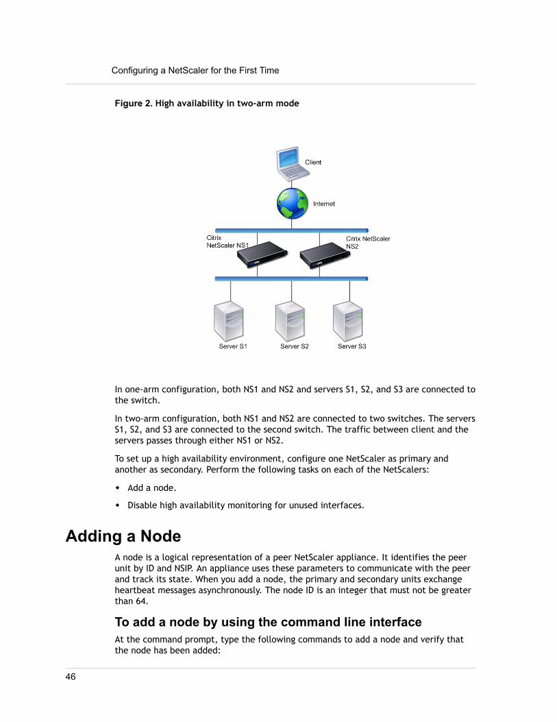
Figure 2. High availability in two-arm mode
In one-arm configuration, both NS1 and NS2 and servers S1, S2, and S3 are connected tothe switch.
In two-arm configuration, both NS1 and NS2 are connected to two switches. The serversS1, S2, and S3 are connected to the second switch. The traffic between client and theservers passes through either NS1 or NS2.
To set up a high availability environment, configure one NetScaler as primary andanother as secondary. Perform the following tasks on each of the NetScalers:
w Add a node.
w Disable high availability monitoring for unused interfaces.
Adding a NodeA node is a logical representation of a peer NetScaler appliance. It identifies the peerunit by ID and NSIP. An appliance uses these parameters to communicate with the peerand track its state. When you add a node, the primary and secondary units exchangeheartbeat messages asynchronously. The node ID is an integer that must not be greaterthan 64.
To add a node by using the command line interfaceAt the command prompt, type the following commands to add a node and verify thatthe node has been added:
Configuring a NetScaler for the First Time
46

w add HA node <id> <IPAddress>w show HA node <id>
Example
add HA node 0 10.102.29.170 Done> show HA node 01) Node ID: 0 IP: 10.102.29.200 (NS200) Node State: UP Master State: Primary SSL Card Status: UP Hello Interval: 200 msecs Dead Interval: 3 secs Node in this Master State for: 1:0:41:50 (days:hrs:min:sec)
To add a node by using the configuration utility1. In the navigation pane, expand System and click High Availability.
The High Availability page appears.
2. On the High Availability page, select the Nodes tab.
3. Click Add.The High Availability Setup dialog box appears.
4. In the High Availability Setup dialog box, in the Remote Node IP Address textbox, type an IP Address (for example, 10.102.29.170).
5. Ensure that the Configure remote system to participate in High Availabilitysetup check box is selected.By default, this check box is selected.
6. Select the Turn off HA monitor on interfaces/channels that are down check boxto disable the HA monitor on interfaces that are down.By default, this check box is selected.
7. Verify that the node you added appears in the list of nodes under the Nodes tab.
Disabling High Availability Monitoring for UnusedInterfaces
The high availability monitor is a virtual entity that monitors an interface. You mustdisable the monitor for interfaces that are not connected or being used for traffic.When the monitor is enabled on an interface whose status is DOWN, the state of thenode becomes NOT UP. In a high availability configuration, a primary node entering aNOT UP state might cause a high availability failover. An interface is marked DOWNunder the following conditions:
w The interface is not connected
47

w The interface is not working properly
w The cable connecting the interface is not working properly
To disable the high availability monitor for an unusedinterface by using the command line interfaceAt the command prompt, type the following commands to disable the high availabilitymonitor for an unused interface and verify that it is disabled:
w set interface <id> -haMonitor OFFw show interface <id>
Example
> set interface 1/8 -haMonitor OFF Done> show interface 1/8 Interface 1/8 (Gig Ethernet 10/100/1000 MBits) #2 flags=0x4000 <ENABLED, DOWN, down, autoneg, 802.1q> MTU=1514, native vlan=1, MAC=00:d0:68:15:fd:3d, downtime 238h55m44s Requested: media AUTO, speed AUTO, duplex AUTO, fctl OFF, throughput 0
RX: Pkts(0) Bytes(0) Errs(0) Drops(0) Stalls(0) TX: Pkts(0) Bytes(0) Errs(0) Drops(0) Stalls(0) NIC: InDisc(0) OutDisc(0) Fctls(0) Stalls(0) Hangs(0) Muted(0) Bandwidth thresholds are not set.
When the high availability monitor is disabled for an unused interface, the output ofthe show interface command for that interface does not include "HAMON."
To disable the high availability monitor for unusedinterfaces by using the configuration utility1. In the navigation pane, expand Network and click Interfaces.
The Interfaces page appears.
2. Select the interface for which the monitor must be disabled.
3. Click Open.The Modify Interface dialog box appears.
4. In HA Monitoring, select the OFF option.
5. Click OK.
6. Verify that, when the interface is selected, "HA Monitoring: OFF" appears in thedetails at the bottom of the page.
Configuring a NetScaler for the First Time
48

Configuring a FIPS Appliance for the First TimeA certificate-key pair is required for HTTPS access to the configuration utility and forsecure remote procedure calls. RPC nodes are internal system entities used for system-to-system communication of configuration and session information. One RPC nodeexists on each appliance. This node stores the password, which is checked against theone provided by the contacting appliance. To communicate with other NetScalerappliances, each appliance requires knowledge of the other appliances, including howto authenticate on the other appliance. RPC nodes maintain this information, whichincludes the IP addresses of the other NetScaler appliances and the passwords used toauthenticate on each.
On a NetScaler MPX appliance virtual appliance, a certificate-key pair is automaticallybound to the internal services. On a FIPS appliance, a certificate-key pair must beimported into the hardware security module (HSM) of a FIPS card. To do so, you mustconfigure the FIPS card, create a certificate-key pair, and bind it to the internalservices.
To configure secure HTTPS by using the commandline interface
1. Initialize the hardware security module (HSM) on the FIPS card of the appliance.For information about initializing the HSM, see "Configuring the HSM."
2. If the appliance is part of a high availability setup, enable the SIM. For informationabout enabling the SIM on the primary and secondary appliances, see " ConfiguringFIPS Appliances in a High Availability Setup."
3. Import the FIPS key into the HSM of the FIPS card of the appliance. At thecommand prompt, type:
import ssl fipskey serverkey -key ns-server.key -inform PEM4. Add a certificate-key pair. At the command prompt, type:
add certkey server -cert ns-server.cert -fipskey serverkey
5. Bind the certificate-key created in the previous step to the following internalservices. At the command prompt, type:
bind ssl service nshttps-127.0.0.1-443 -certkeyname server
bind ssl service nshttps-::11-443 -certkeyname server
To configure secure HTTPS by using theconfiguration utility
1. Initialize the hardware security module (HSM) on the FIPS card of the appliance.For information about initializing the HSM, see "Configuring the HSM."
49
2. If the appliance is part of a high availability setup, enable the secure informationsystem (SIM). For information about enabling the SIM on the primary and secondaryappliances, see " Configuring FIPS Appliances in a High Availability Setup."
3. Import the FIPS key into the HSM of the FIPS card of the appliance. For moreinformation about importing a FIPS key, see "Importing an Existing FIPS Key."
4. In the navigation pane, expand SSL, and then click Certificates.
5. In the details pane, click Install.
6. In the Install Certificate dialog box, type the certificate details.
7. Click Create, and then click Close.
8. In the navigation pane, expand Load Balancing, and then click Services.
9. In the details pane, click Internal Services.
10. Select nshttps-127.0.0.1-443 from the list, and then click Open.
11. On the SSL Settings tab, in the Available pane, select the certificate created instep 7, click Add, and then click OK.
12. Select nshttps-::11-443 from the list, and then click Open.
13. On the SSL Settings tab, in the Available pane, select the certificate created instep 7, click Add, and then click OK.
14. Click OK.
To configure secure RPC by using the commandline interface
1. Initialize the hardware security module (HSM) on the FIPS card of the appliance.For information about initializing the HSM, see "Configuring the HSM."
2. Enable the secure information system (SIM). For information about enabling theSIM on the primary and secondary appliances, see " Configuring FIPS Appliances in aHigh Availability Setup."
3. Import the FIPS key into the HSM of the FIPS card of the appliance. At thecommand prompt, type:
import ssl fipskey serverkey -key ns-server.key -inform PEM4. Add a certificate-key pair. At the command prompt, type:
add certkey server -cert ns-server.cert -fipskey serverkey
5. Bind the certificate-key pair to the following internal services. At the commandprompt, type:
bind ssl service nsrpcs-127.0.0.1-3008 -certkeyname server
bind ssl service nskrpcs-127.0.0.1-3009 -certkeyname server
bind ssl service nsrpcs-::1l-3008 -certkeyname server
Configuring a NetScaler for the First Time
50

6. Enable secure RPC mode. At the command prompt, type:
set ns rpcnode <IP address> -secure YES
To configure secure RPC by using the configurationutility
1. Initialize the hardware security module (HSM) on the FIPS card of the appliance.For information about initializing the HSM, see "Configuring the HSM."
2. Enable the secure information system (SIM). For information about enabling theSIM on the primary and secondary appliances, see " Configuring FIPS Appliances in aHigh Availability Setup."
3. Import the FIPS key into the HSM of the FIPS card of the appliance. For moreinformation about importing a FIPS key, see "Importing an Existing FIPS Key."
4. In the navigation pane, expand SSL, and then click Certificates.
5. In the details pane, click Install.
6. In the Install Certificate dialog box, type the certificate details.
7. Click Create, and then click Close.
8. In the navigation pane, expand Load Balancing, and then click Services.
9. In the details pane, click Internal Services.
10. Select nsrpcs-127.0.0.1-3008 from the list, and then click Open.
11. On the SSL Settings tab, in the Available pane, select the certificate created instep 7, click Add, and then click OK.
12. Select nskrpcs-127.0.0.1-3009 from the list, and then click Open.
13. On the SSL Settings tab, in the Available pane, select the certificate created instep 7, click Add, and then click OK.
14. Select nsrpcs-::11-3008 from the list, and then click Open.
15. On the SSL Settings tab, in the Available pane, select the certificate created instep 7, click Add, and then click OK.
16. Click OK.
17. In the navigation pane, expand Network, and then click RPC.
18. In the details pane, select the IP address, and click Open.
19. In the Configure RPC Node dialog box, select Secure.
20. Click OK.
51

Understanding Common NetworkTopologies
As described in "Physical Deployment Modes," you can deploy the Citrix NetScalerappliance either inline between the clients and servers or in one-arm mode. Inlinemode uses a two-arm topology, which is the most common type of deployment.
Setting Up Common Two-Arm TopologiesIn a two-arm topology, one network interface is connected to the client network andanother network interface is connected to the server network, ensuring that all trafficflows through the appliance. This topology might require you to reconnect yourhardware and also might result in a momentary downtime. The basic variations of two-arm topology are multiple subnets, typically with the appliance on a public subnet andthe servers on a private subnet, and transparent mode, with both the appliance andthe servers on the public network.
Setting Up a Simple Two-Arm Multiple SubnetTopology
One of the most commonly used topologies has the NetScaler appliance inline betweenthe clients and the servers, with a virtual server configured to handle the clientrequests. This configuration is used when the clients and servers reside on differentsubnets. In most cases, the clients and servers reside on public and private subnets,respectively.
For example, consider an appliance deployed in two-arm mode for managing serversS1, S2, and S3, with a virtual server of type HTTP configured on the appliance, andwith HTTP services running on the servers. The servers are on a private subnet and aSNIP is configured on the appliance to communicate with the servers. The Use SNIP(USNIP) option must be enabled on the appliance so that it uses the SNIP instead of theMIP.
As shown in the following figure, the VIP is on public subnet 217.60.10.0, and the NSIP,the servers, and the SNIP are on private subnet 192.168.100.0/24.
Understanding Common Network Topologies
52

Figure 1. Topology Diagram for Two-Arm Mode, Multiple Subnets
Task overview: To deploy a NetScaler appliance in two-arm mode with multiplesubnets
1. Configure the NSIP and default gateway, as described in "Configuring the NetScalerIP Address (NSIP)."
2. Configure the SNIP, as described in "Configuring Subnet IP Addresses."
3. Enable the USNIP option, as described in "To enable or disable USNIP mode."
4. Configure the virtual server and the services, as described in "Creating a VirtualServer" and "Configuring Services."
5. Connect one of the network interfaces to a private subnet and the other interfaceto a public subnet.
Setting Up a Simple Two-Arm Transparent TopologyUse transparent mode if the clients need to access the servers directly, with nointervening virtual server. The server IP addresses must be public because the clientsneed to be able to access them. In the example shown in the following figure, aNetScaler appliance is placed between the client and the server, so the traffic mustpass through the appliance. You must enable L2 mode for bridging the packets. TheNSIP and MIP are on the same public subnet, 217.60.10.0/24.
53

Figure 2. Topology Diagram for Two-Arm, Transparent Mode
Task overview: To deploy a NetScaler in two-arm, transparent mode
1. Configure the NSIP, MIP, and default gateway, as described in "Configuring aNetScaler by Using the Command Line Interface."
2. Enable L2 mode, as described in "Enabling and Disabling Layer 2 Mode."
3. Configure the default gateway of the managed servers as the MIP.
4. Connect the network interfaces to the appropriate ports on the switch.
Setting Up Common One-Arm TopologiesThe two basic variations of one-arm topology are with a single subnet and withmultiple subnets.
Setting Up a Simple One-Arm Single SubnetTopology
You can use a one-arm topology with a single subnet when the clients and serversreside on the same subnet. For example, consider a NetScaler deployed in one-armmode for managing servers S1, S2, and S3. A virtual server of type HTTP is configuredon a NetScaler, and HTTP services are running on the servers. As shown in the following
Understanding Common Network Topologies
54

figure, the NetScaler IP address (NSIP), the Mapped IP address (MIP), and the server IPaddresses are on the same public subnet, 217.60.10.0/24.
Figure 3. Topology Diagram for One-Arm Mode, Single Subnet
Task overview: To deploy a NetScaler in one-arm mode with a single subnet
1. Configure the NSIP, MIP, and the default gateway, as described in "Configuring theNetScaler IP Address (NSIP)".
2. Configure the virtual server and the services, as described in "Creating a VirtualServer" and "Configuring Services".
3. Connect one of the network interfaces to the switch.
Setting Up a Simple One-Arm Multiple SubnetTopology
You can use a one-arm topology with multiple subnets when the clients and serversreside on the different subnets. For example, consider a NetScaler appliance deployedin one-arm mode for managing servers S1, S2, and S3, with the servers connected toswitch SW1 on the network. A virtual server of type HTTP is configured on theappliance, and HTTP services are running on the servers. These three servers are onthe private subnet, so a subnet IP address (SNIP) is configured to communicate withthem. The Use Subnet IP address (USNIP) option must be enabled so that the applianceuses the SNIP instead of a MIP. As shown in the following figure, the virtual IP address
55

(VIP) is on public subnet 217.60.10.0/24; the NSIP, SNIP, and the server IP addresses areon private subnet 192.168.100.0/24.
Figure 4. Topology Diagram for One-Arm Mode, Multiple Subnets
Task overview: To deploy a NetScaler appliance in one-arm mode with multiplesubnets
1. Configure the NSIP and the default gateway, as described in "Configuring theNetScaler IP Address (NSIP)".
2. Configure the SNIP and enable the USNIP option, as described in "ConfiguringSubnet IP Addresses".
3. Configure the virtual server and the services, as described in "Creating a VirtualServer" and "Configuring Services".
4. Connect one of the network interfaces to the switch.
Understanding Common Network Topologies
56
Configuring System Management Settings
Once your initial configuration is in place, you can configure settings to define thebehavior of the Citrix NetScaler appliance and facilitate connection management. Youhave a number of options for handling HTTP requests and responses. Routing, bridging,and MAC based forwarding modes are available for handling packets not addressed tothe NetScaler. You can define the characteristics of your network interfaces and canaggregate the interfaces. To prevent timing problems, you can synchronize theNetScaler clock with a Network Time Protocol (NTP) server. The NetScaler can operatein various DNS modes, including as an authoritative domain name server (ADNS). Youcan set up SNMP for system management and customize syslog logging of systemevents. Before deployment, verify that your configuration is complete and correct.
Configuring System SettingsConfiguration of system settings includes basic tasks such as configuring HTTP ports toenable connection keep-alive and server offload, setting the maximum number ofconnections for each server, and setting the maximum number of requests perconnection. You can enable client IP address insertion for situations in which a proxy IPaddress is not suitable, and you can change the HTTP cookie version.
You can also configure a NetScaler appliance to open FTP connections on a controlledrange of ports instead of ephemeral ports for data connections. This improves security,because opening all ports on the firewall is insecure. You can set the range anywherefrom 1,024 to 64,000.
Before deployment, go through the verification checklists to verify your configuration.To configure HTTP parameters and the FTP port range, use the NetScaler configurationutility.
You can modify the types of HTTP parameters described in the following table.
Table 1. HTTP Parameters
Parameter Type Specifies
HTTP Port Information The web server HTTP portsused by your managedservers. If you specify theports, the applianceperforms requestswitching for any clientrequest that has adestination port matchinga specified port.
57

Parameter Type Specifies
Note: If an incomingclient request is notdestined for a service ora virtual server that isspecifically configuredon the appliance, thedestination port in therequest must match oneof the globallyconfigured HTTP ports.This allows theappliance to performconnection keep-aliveand server off-load.
Limits The maximum number ofconnections to eachmanaged server, and themaximum number ofrequests sent over eachconnection. For example,if you set MaxConnections to 500, andthe appliance is managingthree servers, it can opena maximum of 500connections to each of thethree servers. By default,the appliance can createan unlimited number ofconnections to any of theservers it manages. Tospecify an unlimitednumber of requests perconnection, set MaxRequests to 0.
Note: If you are usingthe Apache HTTPserver, you must setMax Connectionsequal to the value of theMaxClients parameter inthe Apache httpd.conffile. Setting this
Configuring System Management Settings
58

Parameter Type Specifies
parameter is optional forother web servers.
Client IP Insertion Enable/disable insertion ofthe client's IP address intothe HTTP request header.You can specify a name forthe header field in theadjacent text box. When aweb server managed by anappliance receives amapped IP address or asubnet IP address, theserver identifies it as theclient’s IP address. Someapplications need theclient’s IP address forlogging purposes or todynamically determine thecontent to be served bythe web server.
You can enable insertion ofthe actual client IPaddress into the HTTPheader request sent fromthe client to one, some, orall servers managed by theappliance. You can thenaccess the insertedaddress through a minormodification to the server(using an Apache module,ISAPI interface, or NSAPIinterface).
Cookie Version The HTTP cookie versionto use when COOKIEINSERTpersistence is configuredon a virtual server. Thedefault, version 0, is themost common type on theInternet. Alternatively,you can specify version 1.
59
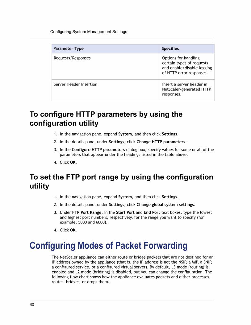
Parameter Type Specifies
Requests/Responses Options for handlingcertain types of requests,and enable/disable loggingof HTTP error responses.
Server Header Insertion Insert a server header inNetScaler-generated HTTPresponses.
To configure HTTP parameters by using theconfiguration utility
1. In the navigation pane, expand System, and then click Settings.
2. In the details pane, under Settings, click Change HTTP parameters.
3. In the Configure HTTP parameters dialog box, specify values for some or all of theparameters that appear under the headings listed in the table above.
4. Click OK.
To set the FTP port range by using the configurationutility
1. In the navigation pane, expand System, and then click Settings.
2. In the details pane, under Settings, click Change global system settings.
3. Under FTP Port Range, in the Start Port and End Port text boxes, type the lowestand highest port numbers, respectively, for the range you want to specify (forexample, 5000 and 6000).
4. Click OK.
Configuring Modes of Packet ForwardingThe NetScaler appliance can either route or bridge packets that are not destined for anIP address owned by the appliance (that is, the IP address is not the NSIP, a MIP, a SNIP,a configured service, or a configured virtual server). By default, L3 mode (routing) isenabled and L2 mode (bridging) is disabled, but you can change the configuration. Thefollowing flow chart shows how the appliance evaluates packets and either processes,routes, bridges, or drops them.
Configuring System Management Settings
60

Figure 1. Interaction between Layer 2 and Layer 3 Modes
An appliance can use the following modes to forward the packets it receives:
w Layer 2 (L2) Mode
w Layer 3 (L3) Mode
w MAC-Based Forwarding Mode
Enabling and Disabling Layer 2 ModeLayer 2 mode controls the Layer 2 forwarding (bridging) function. You can use thismode to configure a NetScaler appliance to behave as a Layer 2 device and bridge thepackets that are not destined for it. When this mode is enabled, packets are notforwarded to any of the MAC addresses, because the packets can arrive on anyinterface of the appliance and each interface has its own MAC address.
With Layer 2 mode disabled (which is the default), the appliance drops packets thatare not destined for one of its MAC address. If another Layer 2 device is installed inparallel with the appliance, Layer 2 mode must be disabled to prevent bridging (Layer
61

2) loops. You can use the configuration utility or the command line to enable Layer 2mode.
Note: The appliance does not support spanning tree protocol. To avoid loops, if youenable L2 mode, do not connect two interfaces on the appliance to the samebroadcast domain.
To enable or disable Layer 2 mode by using the commandline interfaceAt the command prompt, type the following commands to enable/disable Layer 2 modeand verify that it has been enabled/disabled:
w enable ns mode <Mode>w disable ns mode <Mode>w show ns mode
Examples
> enable ns mode l2 Done> show ns mode
Mode Acronym Status ------- ------- ------ 1) Fast Ramp FR ON 2) Layer 2 mode L2 ON . . . Done>
> disable ns mode l2 Done> show ns mode
Mode Acronym Status ------- ------- ------ 1) Fast Ramp FR ON 2) Layer 2 mode L2 OFF . . . Done>
To enable or disable Layer 2 mode by using theconfiguration utility1. In the navigation pane, expand System, and then click Settings.
2. In the details pane, under Modes and Features, click Configure modes.
Configuring System Management Settings
62

3. In the Configure Modes dialog box, to enable Layer 2 mode, select the Layer 2Mode check box. To disable Layer 2 mode, clear the check box.
4. Click OK.The Enable/Disable Mode(s)? message appears in the details pane.
5. Click Yes.
Enabling and Disabling Layer 3 ModeLayer 3 mode controls the Layer 3 forwarding function. You can use this mode toconfigure a NetScaler appliance to look at its routing table and forward packets thatare not destined for it. With Layer 3 mode enabled (which is the default), theappliance performs route table lookups and forwards all packets that are not destinedfor any appliance-owned IP address. If you disable Layer 3 mode, the appliance dropsthese packets.
To enable or disable Layer 3 mode by using the commandline interfaceAt the command prompt, type the following commands to enable/disable Layer 3 modeand verify that it has been enabled/disabled:
w enable ns mode <Mode>w disable ns mode <Mode>w show ns mode
Examples
> enable ns mode l3 Done> show ns mode
Mode Acronym Status ------- ------- ------ 1) Fast Ramp FR ON 2) Layer 2 mode L2 OFF . . . 9) Layer 3 mode (ip forwarding) L3 ON . . . Done>
> disable ns mode l3 Done> show ns mode
Mode Acronym Status ------- ------- ------ 1) Fast Ramp FR ON
63

2) Layer 2 mode L2 OFF . . . 9) Layer 3 mode (ip forwarding) L3 OFF . . . Done>
To enable or disable Layer 3 mode by using theconfiguration utility1. In the navigation pane, expand System, and then click Settings.
2. In the details pane, under Modes and Features, click Configure modes.
3. In the Configure Modes dialog box, to enable Layer 3 mode, select the Layer 3Mode (IP Forwarding) check box. To disable Layer 3 mode, clear the check box.
4. Click OK.The Enable/Disable Mode(s)? message appears in the details pane.
5. Click Yes.
Enabling and Disabling MAC-Based ForwardingMode
You can use MAC-based forwarding to process traffic more efficiently and avoidmultiple-route or ARP lookups when forwarding packets, because the NetScalerappliance remembers the MAC address of the source. To avoid multiple lookups, theappliance caches the source MAC address of every connection for which it performs anARP lookup, and it returns the data to the same MAC address.
MAC-based forwarding is useful when you use VPN devices because the applianceensures that all traffic flowing through a particular VPN passes through the same VPNdevice.
The following figure shows the process of MAC-based forwarding.
Configuring System Management Settings
64

Figure 2. MAC-Based Forwarding Process
When MAC-based forwarding is enabled, the appliance caches the MAC address of:
w The source (a transmitting device such as router, firewall, or VPN device) of theinbound connection.
w The server that responds to the requests.
When a server responds through an appliance, the appliance sets the destination MACaddress of the response packet to the cached address, ensuring that the traffic flows ina symmetric manner, and then forwards the response to the client. The processbypasses the route table lookup and ARP lookup functions. However, when an applianceinitiates a connection, it uses the route and ARP tables for the lookup function. Toenable MAC-based forwarding, use the configuration utility or the command line.
Some deployments require the incoming and outgoing paths to flow through differentrouters. In these situations, MAC-based forwarding breaks the topology design. For aglobal server load balancing (GSLB) site that requires the incoming and outgoing pathsto flow through different routers, you must disable MAC-based forwarding and use theappliance’s default router as the outgoing router.
With MAC-based forwarding disabled and Layer 2 or Layer 3 connectivity enabled, aroute table can specify separate routers for outgoing and incoming connections. Todisable MAC-based forwarding, use the configuration utility or the command line.
65

To enable or disable MAC-based forwarding by using thecommand line interfaceAt the command prompt, type the following commands to enable/disable MAC-basedforwarding mode and verify that it has been enabled/disabled:
w enable ns mode <Mode>w disable ns mode <Mode>w show ns mode
Example
> enable ns mode mbf Done> show ns mode
Mode Acronym Status ------- ------- ------ 1) Fast Ramp FR ON 2) Layer 2 mode L2 OFF . . . 6) MAC-based forwarding MBF ON . . . Done>
> disable ns mode mbf Done> show ns mode
Mode Acronym Status ------- ------- ------ 1) Fast Ramp FR ON 2) Layer 2 mode L2 OFF . . . 6) MAC-based forwarding MBF OFF . . . Done>
To enable or disable MAC-based forwarding by using theconfiguration utility1. In the navigation pane, expand System, and then click Settings.
Configuring System Management Settings
66
2. In the details pane, under Modes and Features group, click Configure modes.
3. In the Configure Modes dialog box, to enable MAC-based forwarding mode, selectthe MAC Based Forwarding check box. To disable MAC-based forwarding mode,clear the check box.
4. Click OK.The Enable/Disable Mode(s)? message appears in the details pane.
5. Click Yes.
Configuring Network InterfacesNetScaler interfaces are numbered in slot/port notation. In addition to modifying thecharacteristics of individual interfaces, you can configure virtual LANs to restrict trafficto specific groups of hosts. You can also aggregate links into high-speed channels.
Virtual LANsThe NetScaler supports (Layer 2) port and IEEE802.1Q tagged virtual LANs (VLANs).VLAN configurations are useful when you need to restrict traffic to certain groups ofstations. You can configure a network interface to belong to multiple VLANs by usingIEEE 802.1q tagging.
You can bind your configured VLANs to IP subnets. The NetScaler (if it is configured asthe default router for the hosts on the subnets) then performs IP forwarding betweenthese VLANs. A NetScaler supports the following types of VLANs.
Default VLANBy default, the network interfaces on a NetScaler are included in a single, port-basedVLAN as untagged network interfaces. This default VLAN has a VID of 1 and existspermanently. It cannot be deleted, and its VID cannot be changed.
Port-Based VLANsA set of network interfaces that share a common, exclusive, Layer 2 broadcastdomain define the membership of a port-based VLAN. You can configure multipleport-based VLANs. When you add an interface to a new VLAN as an untaggedmember, it is automatically removed from the default VLAN.
Tagged VLANA network interface can be a tagged or untagged member of a VLAN. Each networkinterface is an untagged member of only one VLAN (its native VLAN). The untaggednetwork interface forwards the frames for the native VLAN as untagged frames. Atagged network interface can be a part of more than one VLAN. When you configuretagging, be sure that both ends of the link have matching VLAN settings. You can usethe configuration utility to define a tagged VLAN (nsvlan) that can have any portsbound as tagged members of the VLAN. Configuring this VLAN requires a reboot ofthe NetScaler and therefore must be done during initial network configuration.
67

Link Aggregate ChannelsLink aggregation combines incoming data from multiple ports into a single high speedlink. Configuring the link aggregate channel increases the capacity and availability ofthe communication channel between a NetScaler and other connected devices. Anaggregated link is also referred to as a channel.
When a network interface is bound to a channel, the channel parameters haveprecedence over the network interface parameters. A network interface can be boundto only one channel. Binding a network interface to a link aggregate channel changesthe VLAN configuration. That is, binding network interfaces to a channel removes themfrom the VLANs that they originally belonged to and adds them to the default VLAN.However, you can bind the channel back to the old VLAN, or to a new one. Forexample, if you have bound network interfaces 1/2 and 1/3 to a VLAN with ID 2, andthen you bind them to link aggregate channel LA/1, the network interfaces are movedto the default VLAN, but you can bind them to VLAN 2.
Note: You can also use Link Aggregation Control Protocol (LACP) to configure linkaggregation. For more information, see "Configuring Link Aggregation by Using theLink Aggregation Control Protocol."
Configuring Clock SynchronizationYou can configure your NetScaler appliance to synchronize its local clock with aNetwork Time Protocol (NTP) server. This ensures that its clock has the same date andtime settings as the other servers on your network. NTP uses User Datagram Protocol(UDP) port 123 as its transport layer. You have to add NTP servers in the NTPconfiguration file so that the appliance periodically gets updates from these servers.
If you do not have a local NTP server, you can find a list of public, open access, NTPservers at the official NTP site at http://www.ntp.org.
To configure clock synchronization on yourappliance
1. Log on to the command line and enter the shell command.
2. At the shell prompt, copy the ntp.conf file from the /etc directory to the /nsconfig directory. If the file already exists in the /nsconfig directory, makesure that you remove the following entries from the ntp.conf file:
restrict localhostrestrict 127.0.0.2These entries are required only if you want to run the device as a time server.However, this feature is not supported on the NetScaler.
Configuring System Management Settings
68

3. Edit /nsconfig/ntp.conf by typing the IP address for the desired NTP serverunder the file’s server and restrict entries.
4. Create a file named rc.netscaler in the /nsconfig directory, if the file doesnot already exist in the directory.
5. Edit /nsconfig/rc.netscaler by adding the following entry:/usr/sbin/ntpd -c /nsconfig/ntp.conf -l /var/log/ntpd.log &This entry starts the ntpd service, checks the ntp.conf file, and logs messages inthe /var/log directory.
Note: If the time difference between the NetScaler and the time server is morethan 1000 sec, the ntpd service terminates with a message to the NetScaler log.To avoid this, you need to start ntpd with the -g option, which forcibly syncs thetime. Add the following entry in /nsconfig/rc.netscaler:/usr/sbin/ntpd -g -c /nsconfig/ntp.conf -l /var/log/ntpd.log&If you do not want to forcibly sync the time when there is a large difference,you can set the date manually and then start ntpd again. You can check the timedifference between the appliance and the time server by running the followingcommand in the shell:
ntpdate -q <IP address or domain name of the NTP server>
6. Reboot the appliance to enable clock synchronization.
Note: If you want to start time synchronization before you restart the appliance,enter the following command (which you added to the rc.netscaler file in step 5) atthe shell prompt:
/usr/sbin/ntpd -c /nsconfig/ntp.conf -l /var/log/ ntpd.log &
Configuring DNSYou can configure a NetScaler appliance to function as an Authoritative Domain NameServer (ADNS), DNS proxy server, End Resolver, or Forwarder. You can add DNS resourcerecords such as SRV Records, AAAA Records, A Records, MX Records, NS Records, CNAMERecords, PTR Records, and SOA Records. Also, the appliance can balance the load onexternal DNS servers.
A common practice is to configure an appliance as a forwarder. For this configuration,you need to add external name servers. After you have added the external servers, youshould verify that your configuration is correct.
69

You can add, remove, enable, and disable external name servers. You can create aname server by specifying its IP address, or you can configure an existing virtual serveras the name server.
When adding name servers, you can specify IP addresses or virtual IP addresses (VIPs).If you use IP addresses, the appliance load balances requests to the configured nameservers in a round robin manner. If you use VIPs, you can specify any load balancingmethod. For information about using a VIP, see "Load Balancing DNS Servers."
To add a name server by using the command lineinterface
At the command prompt, type the following commands to add a name server and verifythe configuration:
w add dns nameServer <IP>w show dns nameServer <IP>
Example
> add dns nameServer 10.102.29.10 Done> show dns nameServer 10.102.29.101) 10.102.29.10 - State: DOWN Done>
To add a name server by using the configurationutility
1. In the navigation pane, expand DNS, and then click Name Servers.
2. In the details pane, click Add.
3. In the Create Name Server dialog box, select IP Address.
4. In the IP Address text box, type the IP address of the name server (for example,10.102.29.10). If you are adding an external name server, clear the Local checkbox.
5. Click Create, and then click Close.
6. Verify that the name server you added appears in the Name Servers pane.
Configuring SNMPThe Simple Network Management Protocol (SNMP) network management application,running on an external computer, queries the SNMP agent on the NetScaler. The agent
Configuring System Management Settings
70

searches the management information base (MIB) for data requested by the networkmanagement application and sends the data to the application.
SNMP monitoring uses traps messages and alarms. SNMP traps messages areasynchronous events that the agent generates to signal abnormal conditions, which areindicated by alarms. For example, if you want to be informed when CPU utilization isabove 90 percent, you can set up an alarm for that condition. The following figureshows a network with a NetScaler that has SNMP enabled and configured.
Figure 3. SNMP on the NetScaler
The SNMP agent on a NetScaler supports SNMP version 1 (SNMPv1), SNMP version 2(SNMPv2), and SNMP version 3 (SNMPv3). Because it operates in bilingual mode, theagent can handle SNMPv2 queries, such as Get-Bulk, and SNMPv1 queries. The SNMPagent also sends traps compliant with SNMPv2 and supports SNMPv2 data types, such ascounter64. SNMPv1 managers (programs on other servers that request SNMP informationfrom the NetScaler) use the NS-MIB-smiv1.mib file when processing SNMP queries.SNMPv2 managers use the NS-MIB-smiv2.mib file.
The NetScaler supports the following enterprise-specific MIBs:
A subset of standard MIB-2 groupsProvides MIB-2 groups SYSTEM, IF, ICMP, UDP, and SNMP.
A system enterprise MIBProvides system-specific configuration and statistics.
71

To configure SNMP, you specify which managers can query the SNMP agent, add SNMPtrap listeners that will receive the SNMP trap messages, and configure SNMP Alarms.
Adding SNMP ManagersYou can configure a workstation running a management application that complies withSNMP version 1, 2, or 3 to access an appliance. Such a workstation is called an SNMPmanager. If you do not specify an SNMP manager on the appliance, the applianceaccepts and responds to SNMP queries from all IP addresses on the network. If youconfigure one or more SNMP managers, the appliance accepts and responds to SNMPqueries from only those specific IP addresses. When specifying the IP address of anSNMP manager, you can use the netmask parameter to grant access from entiresubnets. You can add a maximum of 100 SNMP managers or networks.
To add an SNMP manager by using the command lineinterfaceAt the command prompt, type the following commands to add an SNMP manager andverify the configuration:
w add snmp manager <IPAddress> ... [-netmask <netmask>]w show snmp manager <IPAddress>
Example
> add snmp manager 10.102.29.5 -netmask 255.255.255.255 Done> show snmp manager 10.102.29.51) 10.102.29.5 255.255.255.255 Done>
To add an SNMP manager by using the configuration utility1. In the navigation pane, expand System, expand SNMP, and then click Managers.
2. In the details pane, click Add.
3. In the Add SNMP Manager dialog box, in the IP Address text box, type the IPaddress of the workstation running the management application (for example,10.102.29.5).
4. Click Create, and then click Close.
5. Verify that the SNMP manager you added appears in the Details section at thebottom of the pane.
Adding SNMP Traps ListenersAfter configuring the alarms, you need to specify the trap listener to which theappliance will send the trap messages. Apart from specifying parameters like IP address
Configuring System Management Settings
72

and the destination port of the trap listener, you can specify the type of trap (eithergeneric or specific) and the SNMP version.
You can configure a maximum of 20 trap listeners for receiving either generic orspecific traps.
To add an SNMP trap listener by using the command lineinterfaceAt the command prompt, type the following command to add an SNMP trap and verifythat it has been added:
w add snmp trap specific <IP>w show snmp trap
Example
> add snmp trap specific 10.102.29.3 Done> show snmp trapType DestinationIP DestinationPort Version SourceIP Min-Severity Community---- ------------- --------------- ------- -------- ------------ ---------generic 10.102.29.9 162 V2 NetScaler IP N/A publicgeneric 10.102.29.5 162 V2 NetScaler IP N/A publicgeneric 10.102.120.101 162 V2 NetScaler IP N/A public...specific 10.102.29.3 162 V2 NetScaler IP - public Done>
To add an SNMP trap listener by using the configurationutility1. In the navigation pane, expand System, expand SNMP, and then click Traps.
2. In the details pane, click Add.
3. In the Create SNMP Trap Destination dialog box, in the Destination IP Addresstext box, type the IP address (for example, 10.102.29.3).
4. Click Create and then click Close.
5. Verify that the SNMP trap you added appears in the Details section at the bottomof the pane.
73

Configuring SNMP AlarmsYou configure alarms so that the appliance generates a trap message when an eventcorresponding to one of the alarms occurs. Configuring an alarm consists of enablingthe alarm and setting the severity level at which a trap is generated. There are fiveseverity levels: Critical, Major, Minor, Warning, and Informational. A trap is sent onlywhen the severity of the alarm matches the severity specified for the trap.
Some alarms are enabled by default. If you disable an SNMP alarm, the appliance willnot generate trap messages when corresponding events occur. For example, if youdisable the Login-Failure SNMP alarm, the appliance will not generate a trap messagewhen a login failure occurs.
To enable or disable an alarm by using the command lineinterfaceAt the command prompt, type the following commands to enable or disable an alarmand verify that it has been enabled or disabled:
w set snmp alarm <trapName> [-state ENABLED | DISABLED ]w show snmp alarm <trapName>
Example
> set snmp alarm LOGIN-FAILURE -state ENABLED Done> show snmp alarm LOGIN-FAILURE Alarm Alarm Threshold Normal Threshold Time State Severity Logging ----- --------------- ---------------- ---- -------- --------- -------- 1) LOGIN-FAILURE N/A N/A N/A ENABLED - ENABLED Done>
To set the severity of the alarm by using the command lineinterfaceAt the command prompt, type the following commands to set the severity of the alarmand verify that the severity has been set correctly:
w set snmp alarm <trapName> [-severity <severity>]w show snmp alarm <trapName>
Example
> set snmp alarm LOGIN-FAILURE -severity Major Done> show snmp alarm LOGIN-FAILURE Alarm Alarm Threshold Normal Threshold Time State Severity Logging ----- --------------- ---------------- ---- -------- --------- --------
Configuring System Management Settings
74

1) LOGIN-FAILURE N/A N/A N/A ENABLED Major ENABLED Done>
To configure alarms by using the configuration utility1. In the navigation pane, expand System, expand SNMP, and then click Alarms.
2. In the details pane, select an alarm (for example, LOGIN-FAILURE), and then clickOpen.
3. In the Configure SNMP Alarm dialog box, to enable the alarm, select the Enablecheck box. To disable the alarm, clear the Enable check box.
4. In the Severity drop-down list, select a severity option (for example, Major).
5. Click OK, and then click Close.
6. Verify that the parameters for the SNMP alarm you configured are correctlyconfigured by viewing the Details section at the bottom of the pane.
Configuring SyslogYou can customize logging of NetScaler and Access Gateway Enterprise Edition accessevents for the needs of your site. You can direct these logs either to files on theNetScaler or to external log servers. The NetScaler uses the Audit Server Loggingfeature for logging the states and status information collected by different modules inthe kernel and by user-level daemons.
Syslog is used to monitor a NetScaler and to log connections, statistics, and so on. Youcan customize the two logging functions for system events messaging and syslog. TheNetScaler internal event message generator passes log entries to the syslog server. Thesyslog server accepts these log entries and logs them. For more information about theAudit Server Logging feature, see "Audit Logging."
Verifying the ConfigurationAfter you finish configuring your system, complete the following checklists to verifyyour configuration.
Configuration Checklist
w The build running is:
w There are no incompatibility issues. (Incompatibility issues are documented in thebuild’s release notes.)
w The port settings (speed, duplex, flow control, monitoring) are the same as theswitch’s port.
w Enough mapped IP addresses have been configured to support all server-sideconnections during peak times.
75
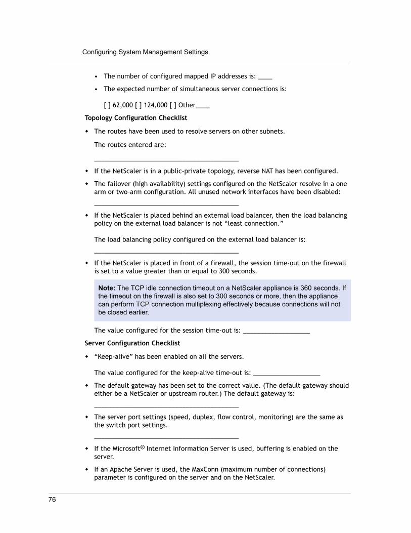
• The number of configured mapped IP addresses is: ____
• The expected number of simultaneous server connections is:
[ ] 62,000 [ ] 124,000 [ ] Other____
Topology Configuration Checklist
w The routes have been used to resolve servers on other subnets.
The routes entered are:
_________________________________________
w If the NetScaler is in a public-private topology, reverse NAT has been configured.
w The failover (high availability) settings configured on the NetScaler resolve in a onearm or two-arm configuration. All unused network interfaces have been disabled:
_________________________________________
w If the NetScaler is placed behind an external load balancer, then the load balancingpolicy on the external load balancer is not “least connection.”
The load balancing policy configured on the external load balancer is:
_________________________________________
w If the NetScaler is placed in front of a firewall, the session time-out on the firewallis set to a value greater than or equal to 300 seconds.
Note: The TCP idle connection timeout on a NetScaler appliance is 360 seconds. Ifthe timeout on the firewall is also set to 300 seconds or more, then the appliancecan perform TCP connection multiplexing effectively because connections will notbe closed earlier.
The value configured for the session time-out is: ___________________
Server Configuration Checklist
w “Keep-alive” has been enabled on all the servers.
The value configured for the keep-alive time-out is: ___________________
w The default gateway has been set to the correct value. (The default gateway shouldeither be a NetScaler or upstream router.) The default gateway is:
_________________________________________
w The server port settings (speed, duplex, flow control, monitoring) are the same asthe switch port settings.
_________________________________________
w If the Microsoft® Internet Information Server is used, buffering is enabled on theserver.
w If an Apache Server is used, the MaxConn (maximum number of connections)parameter is configured on the server and on the NetScaler.
Configuring System Management Settings
76

The MaxConn (maximum number of connections) value that has been set is:
_________________________________________
w If a Netscape® Enterprise Server™ is used, the maximum requests per connectionparameter is set on the NetScaler. The maximum requests per connection value thathas been set is:
_________________________________________
Software Features Configuration Checklist
w Does the Layer 2 mode feature need to be disabled? (Disable if another Layer 2device is working in parallel with a NetScaler.)
Reason for enabling or disabling:
_________________________________________
w Does the MAC-based forwarding feature need to be disabled? (If the MAC addressused by return traffic is different, it should be disabled.)
Reason for enabling or disabling:
_________________________________________
w Does host-based reuse need to be disabled? (Is there virtual hosting on the servers?)
Reason for enabling or disabling:
_________________________________________
w Do the default settings of the surge protection feature need to be changed?
Reason for changing or not changing:
_________________________________________
Access Checklist
w The system IPs can be pinged from the client-side network.
w The system IPs can be pinged from the server-side network.
w The managed server(s) can be pinged through the NetScaler.
w Internet hosts can be pinged from the managed servers.
w The managed server(s) can be accessed through the browser.
w The Internet can be accessed from managed server(s) using the browser.
w The system can be accessed using SSH.
w Admin access to all managed server(s) is working.
Note: When you are using the ping utility, ensure that the pinged server has ICMPECHO enabled, or your ping will not succeed.
Firewall Checklist
77

The following firewall requirements have been met:
w UDP 161 (SNMP)
w UDP 162 (SNMP trap)
w TCP/UDP 3010 (GUI)
w HTTP 80 (GUI)
w TCP 22 (SSH)
Configuring System Management Settings
78

Load Balancing Traffic on a NetScalerAppliance
The load balancing feature distributes client requests across multiple servers tooptimize resource utilization. In a real-world scenario with a limited number of serversproviding service to a large number of clients, a server can become overloaded anddegrade the performance of the server farm. A Citrix NetScaler appliance uses loadbalancing criteria to prevent bottlenecks by forwarding each client request to theserver best suited to handle the request when it arrives.
To configure load balancing, you define a virtual server to proxy multiple servers in aserver farm and balance the load among them.
How Load Balancing WorksWhen a client initiates a connection to the server, a virtual server terminates the clientconnection and initiates a new connection with the selected server, or reuses anexisting connection with the server, to perform load balancing. The load balancingfeature provides traffic management from Layer 4 (TCP and UDP) through Layer 7 (FTP,HTTP, and HTTPS).
The NetScaler appliance uses a number of algorithms, called load balancing methods,to determine how to distribute the load among the servers. The default load balancingmethod is the Least Connections method.
A typical load balancing deployment consists of the entities described in the followingfigure.
79

Figure 1. Load Balancing Architecture
The entities function as follows:
w Virtual server. An entity that is represented by an IP address, a port, and aprotocol. The virtual server IP address (VIP) is usually a public IP address. The clientsends connection requests to this IP address. The virtual server represents a bank ofservers.
w Service. A logical representation of a server or an application running on a server.Identifies the server's IP address, a port, and a protocol. The services are bound tothe virtual servers.
w Server object. An entity that is represented by an IP address. The server object iscreated when you create a service. The IP address of the service is taken as thename of the server object. You can also create a server object and then createservices by using the server object.
w Monitor. An entity that tracks the health of the services. The appliance periodicallyprobes the servers using the monitor bound to each service. If a server does notrespond within a specified response timeout, and the specified number of probesfails, the service is marked DOWN. The appliance then performs load balancingamong the remaining services.
Configuring Load BalancingTo configure load balancing, you must first create services. Then, you create virtualservers and bind the services to the virtual servers. By default, the NetScaler appliance
Load Balancing Traffic on a NetScaler Appliance
80

binds a monitor to each service. After binding the services, verify your configuration bymaking sure that all of the settings are correct.
Note: After you deploy the configuration, you can display statistics that show how theentities in the configuration are performing. Use the statistical utility or the stat lbvserver <vserverName> command.
Optionally, you can assign weights to a service. The load balancing method then usesthe assigned weight to select a service. For getting started, however, you can limitoptional tasks to configuring some basic persistence settings, for sessions that mustmaintain a connection to a particular server, and some basic configuration-protectionsettings.
The following flow chart illustrates the sequence of the configuration tasks.
81

Figure 2. Sequence of Tasks to Configure Load Balancing
Load Balancing Traffic on a NetScaler Appliance
82

Enabling Load BalancingBefore configuring load balancing, make sure that the load balancing feature isenabled.
To enable load balancing by using the command lineinterfaceAt the command prompt, type the following commands to enable load balancing andverify that it is enabled:
w enable feature lbw show feature
Example
> enable feature lb Done> show feature
Feature Acronym Status ------- ------- ------ 1) Web Logging WL OFF 2) Surge Protection SP OFF 3) Load Balancing LB ON . . . 9) SSL Offloading SSL ON . . .Done
To enable load balancing by using the configuration utility1. In the navigation pane, expand System, and then click Settings.
2. In the details pane, under Modes and Features, click Change basic features.
3. In the Configure Basic Features dialog box, select the Load Balancing check box,and then click OK.
4. In the Enable/Disable Feature(s)? message, click Yes.
Configuring Services and a Virtual ServerWhen you have identified the services you want to load balance, you can implementyour initial load balancing configuration by creating the service objects, creating a loadbalancing virtual server, and binding the service objects to the virtual server.
83

To implement the initial load balancing configuration byusing the command line interfaceAt the command prompt, type the following commands to implement and verify theinitial configuration:
w add service <name> <IPaddress> <serviceType> <port>
w add lb vserver <vServerName> <serviceType> [<IPaddress> <port>]
w bind lb vserver <name> <serviceName>
w show service bindings <serviceName>
Example
> add service service-HTTP-1 10.102.29.5 HTTP 80 Done> add lb vserver vserver-LB-1 HTTP 10.102.29.60 80 Done> bind lb vserver vserver-LB-1 service-HTTP-1 Done> show service bindings service-HTTP-1 service-HTTP-1 (10.102.29.5:80) - State : DOWN
1) vserver-LB-1 (10.102.29.60:80) - State : DOWN Done
To implement the initial load balancing configuration byusing the configuration utility1. In the navigation pane, click Load Balancing.
2. In the details pane, under Getting Started, click Load Balancing wizard, andfollow the instructions to create a basic load balancing setup.
3. Return to the navigation pane, expand Load Balancing, and then click VirtualServers.
4. Select the virtual server that you configured and verify that the parametersdisplayed at the bottom of the page are correctly configured.
5. Click Open.
6. Verify that each service is bound to the virtual server by confirming that theActive check box is selected for each service on the Services tab.
Choosing and Configuring Persistence SettingsYou must configure persistence on a virtual server if you want to maintain the states ofconnections on the servers represented by that virtual server (for example, connectionsused in e-commerce). The appliance then uses the configured load balancing methodfor the initial selection of a server, but forwards to that same server all subsequentrequests from the same client.
Load Balancing Traffic on a NetScaler Appliance
84

If persistence is configured, it overrides the load balancing methods once the serverhas been selected. If the configured persistence applies to a service that is down, theappliance uses the load balancing methods to select a new service, and the new servicebecomes persistent for subsequent requests from the client. If the selected service is inan Out Of Service state, it continues to serve the outstanding requests but does notaccept new requests or connections. After the shutdown period elapses, the existingconnections are closed. The following table lists the types of persistence that you canconfigure.
Table 1. Limitations on Number of Simultaneous Persistent Connections
Persistence Type Persistent Connections
Source IP, SSL Session ID, Rule, DESTIP,SRCIPDESTIP
250K
CookieInsert, URL passive, Custom ServerID
Memory limit. In case of CookieInsert, iftime out is not 0, any number ofconnections is allowed until limited bymemory.
If the configured persistence cannot be maintained because of a lack of resources onan appliance, the load balancing methods are used for server selection. Persistence ismaintained for a configured period of time, depending on the persistence type. Somepersistence types are specific to certain virtual servers. The following table shows therelationship.
Table 2. Persistence Types Available for Each Type of Virtual Server
PersistenceTypeHeader1
HTTP HTTPS TCP UDP/IP SSL_Bridge
Source IP YES YES YES YES YES
CookieInsert YES YES NO NO NO
SSL SessionID
NO YES NO NO YES
URL Passive YES YES NO NO NO
CustomServer ID
YES YES NO NO NO
Rule YES YES NO NO NO
SRCIPDESTIP N/A N/A YES YES N/A
DESTIP N/A N/A YES YES N/A
85

You can also specify persistence for a group of virtual servers. When you enablepersistence on the group, the client requests are directed to the same selected serverregardless of which virtual server in the group receives the client request. When theconfigured time for persistence elapses, any virtual server in the group can be selectedfor incoming client requests.
Two commonly used persistence types are persistence based on cookies and persistencebased on server IDs in URLs. For more information about all persistence types, see"Persistence and Persistent Connections."
Configuring Persistence Based on CookiesWhen you enable persistence based on cookies, the NetScaler adds an HTTP cookie intothe Set-Cookie header field of the HTTP response. The cookie contains informationabout the service to which the HTTP requests must be sent. The client stores thecookie and includes it in all subsequent requests, and the NetScaler uses it to selectthe service for those requests. You can use this type of persistence on virtual servers oftype HTTP or HTTPS.
The NetScaler inserts the cookie <NSC_XXXX>= <ServiceIP> <ServicePort>
where:
w <NSC_XXXX> is the virtual server ID that is derived from the virtual server name.w <ServiceIP> is the hexadecimal value of the IP address of the service.w <ServicePort> is the hexadecimal value of the port of the service.
The NetScaler encrypts ServiceIP and ServicePort when it inserts a cookie, and decryptsthem when it receives a cookie.
Note: If the client is not allowed to store the HTTP cookie, the subsequent requests donot have the HTTP cookie, and persistence is not honored.
By default, the NetScaler sends HTTP cookie version 0, in compliance with theNetscape specification. It can also send version 1, in compliance with RFC 2109.
You can configure a timeout value for persistence that is based on HTTP cookies. Notethe following:
w If HTTP cookie version 0 is used, the NetScaler inserts the absolute CoordinatedUniversal Time (GMT) of the cookie’s expiration (the expires attribute of the HTTPcookie), calculated as the sum of the current GMT time on a NetScaler, and thetimeout value.
w If an HTTP cookie version 1 is used, the NetScaler inserts a relative expiration time(Max-Age attribute of the HTTP cookie). In this case, the client software calculatesthe actual expiration time.
Note: Most client software currently installed (Microsoft Internet Explorer andNetscape browsers) understand HTTP cookie version 0; however, some HTTP proxiesunderstand HTTP cookie version 1.
If you set the timeout value to 0, the NetScaler does not specify the expiration time,regardless of the HTTP cookie version used. The expiration time then depends on the
Load Balancing Traffic on a NetScaler Appliance
86

client software, and such cookies are not valid if that software is shut down. Thispersistence type does not consume any system resources. Therefore, it canaccommodate an unlimited number of persistent clients.
An administrator can use the procedure in the following table to change the HTTPcookie version.
To change the HTTP cookie version by using the configuration utility
1. Navigate to System > Settings.
2. In the details pane, click Change HTTP Parameters.
3. In the Configure HTTP Parameters dialog box, under Cookie, select Version 0 orVersion 1.
Note: For information about the parameters, see "Configuring Persistence Based onCookies."
To configure persistence based on cookies by using the command lineinterfaceAt the command prompt, type the following commands to configure persistence basedon cookies and verify the configuration:
w set lb vserver <name> -persistenceType COOKIEINSERTw show lb vserver <name>
Example
> set lb vserver vserver-LB-1 -persistenceType COOKIEINSERT Done> show lb vserver vserver-LB-1 vserver-LB-1 (10.102.29.60:80) - HTTP Type: ADDRESS . . . Persistence: COOKIEINSERT (version 0) Persistence Timeout: 2 min . . . Done>
To configure persistence based on cookies by using the configurationutility
1. In the navigation pane, expand Load Balancing, and then click Virtual Servers.
2. In the details pane, select the virtual server for which you want to configurepersistence (for example, vserver-LB-1), and then click Open.
87

3. In the Configure Virtual Server (Load Balancing) dialog box, on the Method andPersistence tab, in the Persistence list, select COOKIEINSERT.
4. In the Time-out (min) text box, type the time-out value (for example, 2).
5. Click OK.
6. Verify that the virtual server for which you configured persistence is correctlyconfigured by selecting the virtual server and viewing the Details section at thebottom of the pane.
Configuring Persistence Based on Server IDs in URLsThe NetScaler can maintain persistence based on the server IDs in the URLs. In atechnique called URL passive persistence, the NetScaler extracts the server ID from theserver response and embeds it in the URL query of the client request. The server ID isan IP address and port specified as a hexadecimal number. The NetScaler extracts theserver ID from subsequent client requests and uses it to select the server.
URL passive persistence requires configuring either a payload expression or a policyinfrastructure expression specifying the location of the server ID in the client requests.For more information about expressions, see "Policy Configuration and Reference."
Note: If the server ID cannot be extracted from the client requests, server selection isbased on the load balancing method.
Example: Payload Expression
The expression, URLQUERY contains sid= configures the system to extract the server IDfrom the URL query of a client request, after matching token sid=. Thus, a request withthe URL http://www.citrix.com/index.asp?&sid;=c0a864100050 is directed to theserver with the IP address10.102.29.10 and port 80.
The timeout value does not affect this type of persistence, which is maintained as longas the server ID can be extracted from the client requests. This persistence type doesnot consume any system resources, so it can accommodate an unlimited number ofpersistent clients.
Note: For information about the parameters, see "Load Balancing."
To configure persistence based on server IDs in URLs by using thecommand line interfaceAt the command prompt, type the following commands to configure persistence basedon server IDs in URLs and verify the configuration:
w set lb vserver <name> -persistenceType URLPASSIVEw show lb vserver <name>
Example
> set lb vserver vserver-LB-1 -persistenceType URLPASSIVE Done> show lb vserver vserver-LB-1
Load Balancing Traffic on a NetScaler Appliance
88

vserver-LB-1 (10.102.29.60:80) - HTTP Type: ADDRESS . . . Persistence: URLPASSIVE Persistence Timeout: 2 min . . . Done>
To configure persistence based on server IDs in URLs by using theconfiguration utility
1. In the navigation pane, expand Load Balancing, and then click Virtual Servers.
2. In the details pane, select the virtual server for which you want to configurepersistence (for example, vserver-LB-1), and then click Open.
3. In the Configure Virtual Server (Load Balancing) dialog box, on the Method andPersistence tab, in the Persistence list, select URLPASSIVE.
4. In the Time-out (min) text box, type the time-out value (for example, 2).
5. In the Rule text box, enter a valid expression. Alternatively, click Configure nextto the Rule text box and use the Create Expression dialog box to create anexpression.
6. Click OK.
7. Verify that the virtual server for which you configured persistence is correctlyconfigured by selecting the virtual server and viewing the Details section at thebottom of the pane.
Configuring Features to Protect the Load BalancingConfiguration
You can configure URL redirection to provide notifications of virtual servermalfunctions, and you can configure backup virtual servers to take over if a primaryvirtual server becomes unavailable.
Configuring URL RedirectionYou can configure a redirect URL to communicate the status of the appliance in theevent that a virtual server of type HTTP or HTTPS is down or disabled. This URL can bea local or remote link. The appliance uses HTTP 302 redirect.
Redirects can be absolute URLs or relative URLs. If the configured redirect URL containsan absolute URL, the HTTP redirect is sent to the configured location, regardless of theURL specified in the incoming HTTP request. If the configured redirect URL containsonly the domain name (relative URL), the HTTP redirect is sent to a location afterappending the incoming URL to the domain configured in the redirect URL.
89

Note: If a load balancing virtual server is configured with both a backup virtual serverand a redirect URL, the backup virtual server takes precedence over the redirect URL.In this case, a redirect is used when both the primary and backup virtual servers aredown.
To configure a virtual server to redirect client requests to a URL byusing the command line interfaceAt the command prompt, type the following commands to configure a virtual server toredirect client requests to a URL and verify the configuration:
w set lb vserver <name> -redirectURL <URL>
w show lb vserver <name>
Example
> set lb vserver vserver-LB-1 -redirectURL http://www.newdomain.com/mysite/maintenance Done> show lb vserver vserver-LB-1 vserver-LB-1 (10.102.29.60:80) - HTTP Type: ADDRESS State: DOWN Last state change was at Wed Jun 17 08:56:34 2009 (+666 ms) . . . Redirect URL: http://www.newdomain.com/mysite/maintenance . . . Done>
To configure a virtual server to redirect client requests to a URL byusing the configuration utility
1. In the navigation pane, expand Load Balancing, and then click Virtual Servers.
2. In the details pane, select the virtual server for which you want to configure URLredirection (for example, vserver-LB-1), and then click Open.
3. In the Configure Virtual Server (Load Balancing) dialog box, on the Advancedtab, in the Redirect URL text box, type the URL (for example, http://www.newdomain.com/mysite/maintenance), and then click OK.
4. Verify that the redirect URL you configured for the server appears in the Detailssection at the bottom of the pane.
Configuring Backup Virtual ServersIf the primary virtual server is down or disabled, the appliance can direct theconnections or client requests to a backup virtual server that forwards the client traffic
Load Balancing Traffic on a NetScaler Appliance
90

to the services. The appliance can also send a notification message to the clientregarding the site outage or maintenance. The backup virtual server is a proxy and istransparent to the client.
You can configure a backup virtual server when you create a virtual server or when youchange the optional parameters of an existing virtual server. You can also configure abackup virtual server for an existing backup virtual server, thus creating a cascadedbackup virtual server. The maximum depth of cascading backup virtual servers is 10.The appliance searches for a backup virtual server that is up and accesses that virtualserver to deliver the content.
You can configure URL redirection on the primary for use when the primary and thebackup virtual servers are down or have reached their thresholds for handling requests.
Note: If no backup virtual server exists, an error message appears, unless the virtualserver is configured with a redirect URL. If both a backup virtual server and a redirectURL are configured, the backup virtual server takes precedence.
To configure a backup virtual server by using the command lineinterfaceAt the command prompt, type the following commands to configure a backup serverand verify the configuration:
w set lb vserver <name> [-backupVserver <string>]
w show lb vserver <name>
Example
> set lb vserver vserver-LB-1 -backupVserver vserver-LB-2 Done> show lb vserver vserver-LB-1 vserver-LB-1 (10.102.29.60:80) - HTTP Type: ADDRESS State: DOWN Last state change was at Wed Jun 17 08:56:34 2009 (+661 ms) . . . Backup: vserver-LB-2 . . . Done>
To set up a backup virtual server by using the configuration utility
1. In the navigation pane, expand Load Balancing, and then click Virtual Servers.
2. In the details pane, select the virtual server for which you want to configure thebackup virtual server (for example, vserver-LB-1), and then click Open.
91

3. In the Configure Virtual Server (Load Balancing) dialog box, on the Advancedtab, in the Backup Virtual Server list, select the backup virtual server (forexample, vserver-LB-2, and then click OK.
4. Verify that the backup virtual server you configured appears in the Details sectionat the bottom of the pane.
Note: If the primary server goes down and then comes back up, and you want thebackup virtual server to function as the primary server until you explicitlyreestablish the primary virtual server, select the Disable Primary When Downcheck box.
A Typical Load Balancing ScenarioIn a load balancing setup, the NetScaler appliances are logically located between theclient and the server farm, and they manage traffic flow to the servers.
The following figure shows the topology of a basic load balancing configuration.
Figure 3. Basic Load Balancing Topology
The virtual server selects the service and assigns it to serve client requests. Considerthe scenario in the preceding figure, where the services service-HTTP-1 and service-HTTP-2 are created and bound to the virtual server named virtual server-LB-1. Virtualserver-LB-1 forwards the client request to either service-HTTP-1 or service-HTTP-2.The system selects the service for each request by using the Least Connections load
Load Balancing Traffic on a NetScaler Appliance
92

balancing method. The following table lists the names and values of the basic entitiesthat must be configured on the system.
Table 3. LB Configuration Parameter Values
Entity Type Required parameters and sample values
Name IP Address Port Protocol
Virtual Server vserver-LB-1 10.102.29.60 80 HTTP
Services service-HTTP-1 10.102.29.5 8083 HTTP
service-HTTP-2 10.102.29.6 80 HTTP
Monitors Default None None None
The following figure shows the load balancing sample values and required parametersthat are described in the preceding table.
Figure 4. Load Balancing Entity Model
The following tables list the commands used to configure this load balancing setup byusing the command line interface.
93

Table 4. Initial Configuration Tasks
Task Command
To enable load balancing enable feature lb
To create a service namedservice-HTTP-1
add service service-HTTP-1 10.102.29.5 HTTP 80
To create a service namedservice-HTTP-2
add service service-HTTP-2 10.102.29.6 HTTP 80
To create a virtual servernamed vserver-LB-1
add lb vserver vserver-LB-1 HTTP 10.102.29.60 80
To bind a service namedservice-HTTP-1 to a virtualserver named vserver-LB-1
bind lb vserver vserver-LB-1 service-HTTP-1
To bind a service namedservice-HTTP-2 to a virtualserver named vserver-LB-1
bind lb vserver vserver-LB-1 service-HTTP-2
For more information about the initial configuration tasks, see "Enabling LoadBalancing" and "Configuring Services and a Vserver."
Table 5. Verification Tasks
Task Command
To view the properties of avirtual server namedvserver-LB-1
show lb vserver vserver-LB-1
To view the statistics of avirtual server namedvserver-LB-1
stat lb vserver vserver-LB-1
To view the properties of aservice named service-HTTP-1
show service service-HTTP-1
To view the statistics of aservice named service-HTTP-1
stat service service-HTTP-1
To view the bindings of aservice named service-HTTP-1
show service bindings service-HTTP-1
Load Balancing Traffic on a NetScaler Appliance
94

Table 6. Customization Tasks
Task Command
To configure persistence on a virtualserver named vserver-LB-1
set lb vserver vserver-LB-1 -persistenceType SOURCEIP -persistenceMask 255.255.255.255 -timeout 2
To configure COOKIEINSERT persistenceon a virtual server named vserver-LB-1
set lb vserver vserver-LB-1 -persistenceType COOKIEINSERT
To configure URLPassive persistence on avirtual server named vserver-LB-1
set lb vserver vserver-LB-1 -persistenceType URLPASSIVE
To configure a virtual server to redirectthe client request to a URL on a virtualserver named vserver-LB-1
set lb vserver vserver-LB-1 -redirectURLhttp://www.newdomain.com/mysite/maintenance
To set a backup virtual server on a virtualserver named vserver-LB-1
set lb vserver vserver-LB-1 -backupVserver vserver-LB-2
For more information about configuring persistence, see "Choosing and ConfiguringPersistence Settings." For information about configuring a virtual server to redirect aclient request to a URL and setting up a backup virtual server, see "Configuring Featuresto Protect the Load Balancing Configuration."
95

Accelerating Load Balanced Traffic byUsing Compression
Compression is a popular means of optimizing bandwidth usage, and most web browserssupport compressed data. If you enable the compression feature, the NetScalerappliance intercepts requests from clients and determines whether the client canaccept compressed content. After receiving the HTTP response from the server, theappliance examines the content to determine whether it is compressible. If the contentis compressible, the appliance compresses it, modifies the response header to indicatethe type of compression performed, and forwards the compressed content to theclient.
NetScaler compression is a policy-based feature. A policy filters requests and responsesto identify responses to be compressed, and specifies the type of compression to applyto each response. The appliance provides several built-in policies to compress commonMIME types such as text/html, text/plain, text/xml, text/css, text/rtf, application/msword, application/vnd.ms-excel, and application/vnd.ms-powerpoint. You can alsocreate custom policies. The appliance does not compress compressed MIME types suchas application/octet-stream, binary, bytes, and compressed image formats such as GIFand JPEG.
To configure compression, you must enable it globally and on each service that willprovide responses that you want compressed. If you have configured virtual servers forload balancing or content switching, you should bind the polices to the virtual servers.Otherwise, the policies apply to all traffic that passes through the appliance.
Note: For more information about compression, see "Compression."
Compression Configuration Task SequenceThe following flow chart shows the sequence of tasks for configuring basic compressionin a load balancing setup.
Accelerating Load Balanced Traffic by Using Compression
96

Figure 1. Sequence of Tasks to Configure Compression
Note: The steps in the above figure assume that load balancing has already beenconfigured. For information about configuring load balancing, or for more informationabout services, see "Load Balancing."
If you want to configure something other than a basic compression setup, (forexample, if you need to configure optional parameters in addition to the requiredparameters) see "Compression."
Enabling CompressionBy default, compression is not enabled. You must enable the compression feature toallow compression of HTTP responses that are sent to the client.
To enable compression by using the command lineinterface
At the command prompt, type the following commands to enable compression andverify the configuration:
w enable ns feature CMPw show ns feature
97

Example
> enable ns feature CMPDone> show ns feature Feature Acronym Status ------- ------- ------1) Web Logging WL ON2) Surge Protection SP OFF.7) Compression Control CMP ON8) Priority Queuing PQ OFF.Done
To enable compression by using the configurationutility
1. In the navigation pane, expand System, and then click Settings.
2. In the details pane, under Modes and Features, click Change basic features.
3. In the Configure Basic Features dialog box, select the Compression check box,and then click OK.
4. In the Enable/Disable Feature(s)? dialog box, click Yes.
Configuring Services to Compress DataIn addition to enabling compression globally, you must enable it on each service thatwill deliver files to be compressed. To create a service, see "Configuring Services."
To enable compression on a service by using thecommand line
At the command prompt, type the following commands to enable compression on aservice and verify the configuration:
w set service <name> -CMP YES
w show service <name>
Example
> show service SVC_HTTP1
Accelerating Load Balanced Traffic by Using Compression
98

SVC_HTTP1 (10.102.29.18:80) - HTTPState: UPLast state change was at Tue Jun 16 06:19:14 2009 (+737 ms)Time since last state change: 0 days, 03:03:37.200Server Name: 10.102.29.18Server ID : 0 Monitor Threshold : 0Max Conn: 0 Max Req: 0 Max Bandwidth: 0 kbitsUse Source IP: NOClient Keepalive(CKA): NOAccess Down Service: NOTCP Buffering(TCPB): NOHTTP Compression(CMP): YESIdle timeout: Client: 180 sec Server: 360 secClient IP: DISABLEDCacheable: NOSC: OFFSP: OFFDown state flush: ENABLED 1) Monitor Name: tcp-defaultState: DOWN Weight: 1Probes: 1095 Failed [Total: 1095 Current: 1095]Last response: Failure - TCP syn sent, reset received.Response Time: N/ADone
To enable compression on a service by using theconfiguration utility
1. In the navigation pane, expand Load Balancing, and then click Services.
2. In the details pane, select the service for which you want to configure compression(for example, service-HTTP-1), and then click Open.
3. On the Advanced tab, under Settings, select the Compression check box, andthen click OK.
4. Verify that, when the service is selected, HTTP Compression(CMP): ONappears in the Details section at the bottom of the pane.
Binding a Compression Policy to a VirtualServer
If you bind a policy to a virtual server, the policy is evaluated only by the servicesassociated with that virtual server. You can bind compression policies to a virtual servereither from the Configure Virtual Server (Load Balancing) dialog box or from theCompression Policy Manager dialog box. This topic includes instructions to bindcompression policies to a load balancing virtual server by using the Configure VirtualServer (Load Balancing) dialog box. For information about how you can bind a
99

compression policy to a load balancing virtual server by using the Compression PolicyManager dialog box, see "Configuring and Binding Policies with the Policy Manager."
To bind or unbind a compression policy to a virtualserver by using the command line
At the command prompt, type the following commands to bind or unbind a compressionpolicy to a load balancing virtual server and verify the configuration:
w (bind|unbind) lb vserver <name> -policyName <string>w show lb vserver <name>
Example
> bind lb vserver lbvip -policyName ns_cmp_msappDone> show lb vserver lbviplbvip (8.7.6.6:80) - HTTP Type: ADDRESSState: UPLast state change was at Thu May 28 05:37:21 2009 (+685 ms)Time since last state change: 19 days, 04:26:50.470Effective State: UPClient Idle Timeout: 180 secDown state flush: ENABLEDDisable Primary Vserver On Down : DISABLEDPort Rewrite : DISABLEDNo. of Bound Services : 1 (Total) 1 (Active)Configured Method: LEASTCONNECTIONCurrent Method: Round Robin, Reason: Bound service's state changed to UPMode: IPPersistence: NONEVserver IP and Port insertion: OFFPush: DISABLED Push VServer:Push Multi Clients: NOPush Label Rule: Bound Service Groups:1) Group Name: Service-Group-1 1) Service-Group-1 (10.102.29.252: 80) - HTTP State: UP Weight: 1 1) Policy : ns_cmp_msapp Priority:0Done
Accelerating Load Balanced Traffic by Using Compression
100

To bind or unbind a compression policy to a loadbalancing virtual server by using the configurationutility
1. In the navigation pane, expand Load Balancing, and then click Virtual Servers.
2. In the details pane, select the virtual server to which you want to bind or unbind acompression policy (for example, Vserver-LB-1), and then click Open.
3. In the Configure Virtual Server (Load Balancing) dialog box, on the Policies tab,click Compression.
4. Do one of the following:
• To bind a compression policy, click Insert Policy, and then select the policy youwant to bind to the virtual server.
• To unbind a compression policy, click the name of the policy you want to unbindfrom the virtual server, and then click Unbind Policy.
5. Click OK.
101

Securing Load Balanced Traffic by UsingSSL
The Citrix NetScaler SSL offload feature transparently improves the performance ofweb sites that conduct SSL transactions. By offloading CPU-intensive SSL encryptionand decryption tasks from the local web server to the appliance, SSL offloading ensuressecure delivery of web applications without the performance penalty incurred whenthe server processes the SSL data. Once the SSL traffic is decrypted, it can beprocessed by all standard services. The SSL protocol works seamlessly with varioustypes of HTTP and TCP data and provides a secure channel for transactions using suchdata.
To configure SSL, you must first enable it. Then, you configure HTTP or TCP servicesand an SSL virtual server on the appliance, and bind the services to the virtual server.You must also add a certificate-key pair and bind it to the SSL virtual server. If you useOutlook Web Access servers, you must create an action to enable SSL support and apolicy to apply the action. An SSL virtual server intercepts incoming encrypted trafficand decrypts it by using a negotiated algorithm. The SSL virtual server then forwardsthe decrypted data to the other entities on the appliance for appropriate processing.
SSL Configuration Task SequenceTo configure SSL, you must first enable it. Then, you must create an SSL virtual serverand HTTP or TCP services on the NetScaler. Finally, you must bind a valid SSLcertificate and the configured services to the SSL virtual server.
An SSL virtual server intercepts incoming encrypted traffic and decrypts it using anegotiated algorithm. The SSL virtual server then forwards the decrypted data to theother entities on the NetScaler for appropriate processing.
The following flow chart shows the sequence of tasks for configuring a basic SSL offloadsetup.
Securing Load Balanced Traffic by Using SSL
102

Figure 1. Sequence of Tasks to Configure SSL Offloading
103

Enabling SSL OffloadYou should enable the SSL feature before configuring SSL offload. You can configureSSL-based entities on the appliance without enabling the SSL feature, but they will notwork until you enable SSL.
To enable SSL by using the command line interfaceAt the command prompt, type the following commands to enable SSL Offload andverify the configuration:
w enable ns feature SSLw show ns feature
Example
> enable ns feature ssl Done > show ns feature Feature Acronym Status ------- ------- ------ 1) Web Logging WL ON 2) SurgeProtection SP OFF 3) Load Balancing LB ON . . . 9) SSL Offloading SSL ON 10) Global Server Load Balancing GSLB ON . . Done >
To enable SSL by using the configuration utility1. In the navigation pane, expand System, and then click Settings.
2. In the details pane, under Modes and Features, click Change basic features.
3. Select the SSL Offloading check box, and then click OK.
4. In the Enable/Disable Feature(s)? message box, click Yes.
Creating HTTP ServicesA service on the appliance represents an application on a server. Once configured,services are in the disabled state until the appliance can reach the server on thenetwork and monitor its status. This topic covers the steps to create an HTTP service.
Note: For TCP traffic, perform the procedures in this and the following topics, butcreate TCP services instead of HTTP services.
Securing Load Balanced Traffic by Using SSL
104

To add an HTTP service by using the command lineinterface
At the command prompt, type the following commands to add a HTTP service andverify the configuration:
w add service <name> (<IP> | <serverName>) <serviceType> <port>w show service <name>
> add service SVC_HTTP1 10.102.29.18 HTTP 80 Done> show service SVC_HTTP1 SVC_HTTP1 (10.102.29.18:80) - HTTP State: UP Last state change was at Wed Jul 15 06:13:05 2009 Time since last state change: 0 days, 00:00:15.350 Server Name: 10.102.29.18 Server ID : 0 Monitor Threshold : 0 Max Conn: 0 Max Req: 0 Max Bandwidth: 0 kbits Use Source IP: NO Client Keepalive(CKA): NO Access Down Service: NO TCP Buffering(TCPB): NO HTTP Compression(CMP): YES Idle timeout: Client: 180 sec Server: 360 sec Client IP: DISABLED Cacheable: NO SC: OFF SP: OFF Down state flush: ENABLED
1) Monitor Name: tcp-default State: UP Weight: 1 Probes: 4 Failed [Total: 0 Current: 0] Last response: Success - TCP syn+ack received. Response Time: N/A Done
To add an HTTP service by using the configurationutility
1. In the navigation pane, expand SSL Offload, and then click Services.
2. In details pane, click Add.
105

3. In the Create Service dialog box, in the Service Name, Server, and Port textboxes, type the name of the service, IP address, and port (for example,SVC_HTTP1, 10.102.29.18, and 80).
4. In the Protocol list, select the type of the service (for example, HTTP).
5. Click Create, and then click Close.The HTTP service you configured appears in the Services page.
6. Verify that the parameters you configured are correctly configured by selecting theservice and viewing the Details section at the bottom of the pane.
For more information about services, see "Configuring Services."
Adding an SSL-Based Virtual ServerIn a basic SSL offloading setup, the SSL virtual server intercepts encrypted traffic,decrypts it, and sends the clear text messages to the services that are bound to thevirtual server. Offloading CPU-intensive SSL processing to the appliance allows theback-end servers to process a greater number of requests.
To add an SSL-based virtual server by using thecommand line interface
At the command prompt, type the following commands to create an SSL-based virtualserver and verify the configuration:
w add lb vserver <name> <serviceType> [<IPAddress> <port>]w show lb vserver <name>
Example
> add lb vserver vserver-SSL-1 SSL 10.102.29.50 443 Done > show lb vserver vserver-SSL-1 vserver-SSL-1 (10.102.29.50:443) - SSL Type: ADDRESS State: DOWN[Certkey not bound] Last state change was at Tue Jun 16 06:33:08 2009 (+176 ms) Time since last state change: 0 days, 00:03:44.120 Effective State: DOWN Client Idle Timeout: 180 sec Down state flush: ENABLED Disable Primary Vserver On Down : DISABLED No. of Bound Services : 0 (Total) 0 (Active) Configured Method: LEASTCONNECTION Mode: IP Persistence: NONE Vserver IP and Port insertion: OFF Push: DISABLED Push VServer: Push Multi Clients: NO Push Label Rule: Done
Securing Load Balanced Traffic by Using SSL
106

Caution: To ensure secure connections, you must bind a valid SSL certificate tothe SSL-based virtual server before you enable it.
To add an SSL-based virtual server by using theconfiguration utility
1. In the navigation pane, expand SSL Offload, and then click Virtual Servers.
2. In the details pane, click Add.
3. In the Create Virtual Server (SSL Offload) dialog box, in the Name, IP Address,and Port text boxes, type the name of the virtual server, IP address, and port (forexample, Vserver-SSL-1, 10.102.29.50, and 443).
4. In the Protocol list, select the type of the virtual server, for example, SSL.
5. Click Create, and then click Close.
6. Verify that the parameters you configured are correctly configured by selecting thevirtual server and viewing the Details section at the bottom of the pane. Thevirtual server is marked as DOWN because a certificate-key pair and services havenot been bound to it.
Caution: To ensure secure connections, you must bind a valid SSL certificate tothe SSL-based virtual server before you enable it.
Binding Services to the SSL Virtual ServerAfter decrypting the incoming data, the SSL virtual server forwards the data to theservices that you have bound to the virtual server.
Data transfer between the appliance and the servers can be encrypted or in clear text.If the data transfer between the appliance and the servers is encrypted, the entiretransaction is secure from end to end. For more information about configuring thesystem for end-to-end security, see "SSL Offload and Acceleration."
To bind a service to a virtual server by using thecommand line interface
At the command prompt, type the following commands to bind service to the SSLvirtual server and verify the configuration:
w bind lb vserver <name> <serviceName>w show lb vserver <name>
107

Example
> bind lb vserver vserver-SSL-1 SVC_HTTP1 Done > show lb vserver vserver-SSL-1 vserver-SSL-1 (10.102.29.50:443) - SSL Type: ADDRESS State: DOWN[Certkey not bound] Last state change was at Tue Jun 16 06:33:08 2009 (+174 ms) Time since last state change: 0 days, 00:31:53.70 Effective State: DOWN Client Idle Timeout: 180 sec Down state flush: ENABLED Disable Primary Vserver On Down : DISABLED No. of Bound Services : 1 (Total) 0 (Active) Configured Method: LEASTCONNECTION Mode: IP Persistence: NONE Vserver IP and Port insertion: OFF Push: DISABLED Push VServer: Push Multi Clients: NO Push Label Rule: 1) SVC_HTTP1 (10.102.29.18: 80) - HTTP State: DOWN Weight: 1 Done
To bind a service to a virtual server by using theconfiguration utility
1. In the navigation pane, expand SSL Offload, and then click Virtual Servers.
2. In the details pane, select a virtual server, and then click Open.
3. On the Services tab, in the Active column, select the check boxes next to theservices that you want to bind to the selected virtual server.
4. Click OK.
5. Verify that the Number of Bound Services counter in the Details section at thebottom of the pane is incremented by the number of services that you bound tothe virtual server.
Adding a Certificate Key PairAn SSL certificate is an integral element of the SSL Key-Exchange and encryption/decryption process. The certificate is used during SSL handshake to establish theidentity of the SSL server. You can use a valid, existing SSL certificate that you have onthe NetScaler appliance, or you can create your own SSL certificate. The appliancesupports RSA/DSA certificates of up to 4096 bits.
Securing Load Balanced Traffic by Using SSL
108

Note: Citrix recommends that you use a valid SSL certificate that has been issued bya trusted certificate authority. Invalid certificates and self-created certificates are notcompatible with all SSL clients.
Before a certificate can be used for SSL processing, you must pair it with itscorresponding key. The certificate key pair is then bound to the virtual server and usedfor SSL processing.
To add a certificate key pair by using the commandline interface
At the command prompt, type the following commands to create a certificate key pairand verify the configuration:
w add ssl certKey <certkeyName> -cert <string> [-key <string>]
w show sslcertkey <name>
Example
> add ssl certKey CertKey-SSL-1 -cert ns-root.cert -key ns-root.key Done > show sslcertkey CertKey-SSL-1 Name: CertKey-SSL-1 Status: Valid, Days to expiration:4811 Version: 3 Serial Number: 00 Signature Algorithm: md5WithRSAEncryption Issuer: C=US,ST=California,L=San Jose,O=Citrix ANG,OU=NS Internal,CN=de fault Validity Not Before: Oct 6 06:52:07 2006 GMT Not After : Aug 17 21:26:47 2022 GMT Subject: C=US,ST=California,L=San Jose,O=Citrix ANG,OU=NS Internal,CN=d efault Public Key Algorithm: rsaEncryption Public Key size: 1024 Done
To add a certificate key pair by using theconfiguration utility
1. In the navigation pane, expand SSL, and then click Certificates.
2. In the details pane, click Add.
3. In the Install Certificate dialog box, in the Certificate-Key Pair Name text box,type a name for the certificate key pair you want to add, for example, Certkey-SSL-1.
109

4. Under Details, in Certificate File Name, click Browse (Appliance) to locate thecertificate.Both the certificate and the key are stored in the /nsconfig/ssl/ folder on theappliance. To use a certificate present on the local system, select Local.
5. Select the certificate you want to use, and then click Select.
6. In Private Key File Name, click Browse (Appliance) to locate the private key file.To use a private key present on the local system, select Local.
7. Select the key you want to use and click Select.To encrypt the key used in the certificate key pair, type the password to be usedfor encryption in the Password text box.
8. Click Install.
9. Double-click the certificate key pair and, in the Certificate Details window, verifythat the parameters have been configured correctly and saved.
Binding an SSL Certificate Key Pair to theVirtual Server
After you have paired an SSL certificate with its corresponding key, you must bind thecertificate key pair to the SSL virtual server so that it can be used for SSL processing.Secure sessions require establishing a connection between the client computer and anSSL-based virtual server on the appliance. SSL processing is then carried out on theincoming traffic at the virtual server. Therefore, before enabling the SSL virtual serveron the appliance, you need to bind a valid SSL certificate to the SSL virtual server.
To bind an SSL certificate key pair to a virtual serverby using the command line interface
At the command prompt, type the following commands to bind an SSL certificate keypair to a virtual server and verify the configuration:
w bind ssl vserver <vServerName> -certkeyName <string>
w show ssl vserver <name>
Example
> bind ssl vserver Vserver-SSL-1 -certkeyName CertKey-SSL-1 Done > show ssl vserver Vserver-SSL-1
Advanced SSL configuration for VServer Vserver-SSL-1: DH: DISABLED Ephemeral RSA: ENABLED Refresh Count: 0 Session Reuse: ENABLED Timeout: 120 seconds Cipher Redirect: ENABLED SSLv2 Redirect: ENABLED
Securing Load Balanced Traffic by Using SSL
110

ClearText Port: 0 Client Auth: DISABLED SSL Redirect: DISABLED Non FIPS Ciphers: DISABLED SSLv2: DISABLED SSLv3: ENABLED TLSv1: ENABLED
1) CertKey Name: CertKey-SSL-1 Server Certificate 1) Cipher Name: DEFAULT Description: Predefined Cipher Alias Done
To bind an SSL certificate key pair to a virtual serverby using the configuration utility
1. In the navigation pane, expand SSL Offload, and then click Virtual Servers.
2. Select the virtual server to which you want to bind the certificate key pair, forexample, Vserver-SSL-1, and click Open.
3. In the Configure Virtual Server (SSL Offload) dialog box, on the SSL Settings tab,under Available, select the certificate key pair that you want to bind to the virtualserver (for example, Certkey-SSL-1), and then click Add.
4. Click OK.
5. Verify that the certificate key pair that you selected appears in the Configuredarea.
Configuring Support for Outlook Web AccessIf you use Outlook Web Access (OWA) servers on your NetScaler appliance, you mustconfigure the appliance to insert a special header field, FRONT-END-HTTPS: ON, inHTTP requests directed to the OWA servers, so that the servers generate URL links ashttps:// instead of http://.
Note: You can enable OWA support for HTTP-based SSL virtual servers and servicesonly. You cannot apply it for TCP-based SSL virtual servers and services.
To configure OWA support, do the following:
w Create an SSL action to enable OWA support.
w Create an SSL policy.
w Bind the policy to the SSL virtual server.
111

Creating an SSL Action to Enable OWA SupportBefore you can enable Outlook Web Access (OWA) support, you must create an SSLaction. SSL actions are bound to SSL policies and triggered when incoming datamatches the rule specified by the policy.
To create an SSL action to enable OWA support by usingthe command line interfaceAt the command prompt, type the following commands to create an SSL action toenable OWA support and verify the configuration:
w add ssl action <name> -OWASupport ENABLED
w show SSL action <name>
> add ssl action Action-SSL-OWA -OWASupport enabled Done > show SSL action Action-SSL-OWA Name: Action-SSL-OWA Data Insertion Action: OWA Support: ENABLED Done
To create an SSL action to enable OWA support by usingthe configuration utility1. In the navigation pane, expand SSL, and then click Policies.
2. In the details pane, on the Actions tab, click Add.
3. In the Create SSL Action dialog box, in the Name text box, type Action-SSL-OWA.
4. Under Outlook Web Access, select Enabled.
5. Click Create, and then click Close.
6. Verify that Action-SSL-OWA appears in the SSL Actions page.
Creating SSL PoliciesSSL policies are created by using the policy infrastructure. Each SSL policy has an SSLaction bound to it, and the action is carried out when incoming traffic matches the rulethat has been configured in the policy.
To create an SSL policy by using the command lineinterfaceAt the command prompt, type the following commands to configure an SSL policy andverify the configuration:
w add ssl policy <name> -rule <expression> -reqAction <string>
Securing Load Balanced Traffic by Using SSL
112

w show ssl policy <name>
Example
> add ssl policy Policy-SSL-1 -rule ns_true -reqaction Action-SSL-OWA Done > show ssl policy Policy-SSL-1 Name: Policy-SSL-1 Rule: ns_true Action: Action-SSL-OWA Hits: 0 Policy is bound to following entities 1) PRIORITY : 0 Done
To create an SSL policy by using the configuration utility1. In the navigation pane, expand SSL, and then click Policies.
2. In the details pane, click Add.
3. In the Create SSL Policy dialog box, in the Name text box, type the name of theSSL Policy (for example, Policy-SSL-1).
4. In Request Action, select the configured SSL action that you want to associatewith this policy (for example, Action-SSL-OWA).The ns_true general expression applies the policy to all successful SSL handshaketraffic. However, if you need to filter specific responses, you can create policieswith a higher level of detail. For more information about configuring granularpolicy expressions, see "Understanding Policies and Expressions."
5. In Named Expressions, choose the built-in general expression ns_true and clickAdd Expression. The expression ns_true now appears in the Expression text box.
6. Click Create, and then click Close.
7. Verify that the policy is correctly configured by selecting the policy and viewingthe Details section at the bottom of the pane.
Binding the SSL Policy to an SSL Virtual ServerAfter you configure an SSL policy for Outlook Web Access, bind the policy to a virtualserver that will intercept incoming Outlook traffic. If the incoming data matches any ofthe rules configured in the SSL policy, the policy is triggered and the action associatedwith it is carried out.
To bind an SSL policy to an SSL virtual server by using thecommand line interfaceAt the command prompt, type the following commands to bind an SSL policy to an SSLvirtual server and verify the configuration:
w bind ssl vserver <vServerName> -policyName <string>
113

w show ssl vserver <name>
Example
> bind ssl vserver Vserver-SSL-1 -policyName Policy-SSL-1 Done > show ssl vserver Vserver-SSL-1 Advanced SSL configuration for VServer Vserver-SSL-1: DH: DISABLED Ephemeral RSA: ENABLED Refresh Count: 0 Session Reuse: ENABLED Timeout: 120 seconds Cipher Redirect: ENABLED SSLv2 Redirect: ENABLED ClearText Port: 0 Client Auth: DISABLED SSL Redirect: DISABLED Non FIPS Ciphers: DISABLED SSLv2: DISABLED SSLv3: ENABLED TLSv1: ENABLED
1) CertKey Name: CertKey-SSL-1 Server Certificate
1) Policy Name: Policy-SSL-1 Priority: 0 1) Cipher Name: DEFAULT Description: Predefined Cipher Alias Done>
To bind an SSL policy to an SSL virtual server by using theconfiguration utility1. In the navigation pane, expand SSL Offload, and then click Virtual Servers.
2. In the details pane, select the virtual server (for example, Vserver-SSL-1), andthen click Open.
3. In the Configure Virtual Server (SSL Offload) dialog box, click Insert Policy, andthen select the policy that you want to bind to the SSL virtual server. Optionally,you can double-click the Priority field and type a new priority level.
4. Click OK.
Securing Load Balanced Traffic by Using SSL
114

Features at a Glance
Citrix NetScaler features can be configured independently or in combinations toaddress specific needs. Although some features fit more than one category, thenumerous NetScaler features can generally be categorized as application switching andtraffic management features, application acceleration features, and applicationsecurity and firewall features, and an application visibility feature.
To understand the order in which the features perform their processing, see "ProcessingOrder of Features."
Application Switching and Traffic ManagementFeatures
SSL OffloadingTransparently offloads SSL encryption and decryption from web servers, freeingserver resources to service content requests. SSL places a heavy burden on anapplication's performance and can render many optimization measures ineffective.SSL offload and acceleration allow all the benefits of Citrix Request Switchingtechnology to be applied to SSL traffic, ensuring secure delivery of web applicationswithout degrading end-user performance.
For more information, see "SSL Offload and Acceleration."
Access Control ListsCompares incoming packets to Access Control Lists (ACLs). If a packet matches anACL rule, the action specified in the rule is applied to the packet. Otherwise, thedefault action (ALLOW) is applied and the packet is processed normally. For theappliance to compare incoming packets to the ACLs, you have to apply the ACLs. AllACLs are enabled by default, but you have to apply them in order for the NetScalerto compare incoming packets against them. If an ACL is not required to be a part ofthe lookup table, but still needs to be retained in the configuration, it should bedisabled before the ACLs are applied. A NetScaler does not compare incomingpackets to disabled ACLs.
For more information, see "Access Control Lists."
Load BalancingLoad balancing decisions are based on a variety of algorithms, including round robin,least connections, weighted least bandwidth, weighted least packets, minimumresponse time, and hashing based on URL, domain source IP, or destination IP. Boththe TCP and UDP protocols are supported, so the NetScaler can load balance alltraffic that uses those protocols as the underlying carrier (for example, HTTP, HTTPS,UDP, DNS, NNTP, and general firewall traffic). In addition, the NetScaler can maintain
115

session persistence based on source IP, cookie, server, group, or SSL session. It allowsusers to apply custom Extended Content Verification (ECV) to servers, caches,firewalls and other infrastructure devices to ensure that these systems arefunctioning properly and are providing the right content to users. It can also performhealth checks using ping, TCP, or HTTP URL, and the user can create monitors basedon Perl scripts. To provide high-scale WAN optimization, the CloudBridge appliancesdeployed at data centers can be load balanced through NetScaler appliances. Thebandwidth and number of concurrent sessions can be improved significantly.
For more information, see "Load Balancing."
Content SwitchingDetermines the server to which to send the request on the basis of configuredcontent switching policies. Policy rules can be based on the IP address, URL, andHTTP headers. This allows switching decisions to be based on user and devicecharacteristics such as who the user is, what type of agent is being used, and whatcontent the user requested.
For more information, see "Content Switching."
Global Server Load Balancing (GSLB)Extends the traffic management capabilities of a NetScaler to include distributedInternet sites and global enterprises. Whether installations are spread acrossmultiple network locations or multiple clusters in a single location, the NetScalermaintains availability and distributes traffic across them. It makes intelligent DNSdecisions to prevent users from being sent to a site that is down or overloaded. Whenthe proximity-based GSLB method is enabled, the NetScaler can make load balancingdecisions based on the proximity of the client’s local DNS server (LDNS) in relation todifferent sites. The main benefit of the proximity-based GSLB method is fasterresponse time resulting from the selection of the closest available site.
For more information, see "Global Server Load Balancing."
Dynamic RoutingEnables routers to obtain topology information, routes, and IP addresses fromneighboring routers automatically. When dynamic routing is enabled, thecorresponding routing process listens to route updates and advertises routes. Therouting processes can also be placed in passive mode. Routing protocols enable anupstream router to load balance traffic to identical virtual servers hosted on twostandalone NetScaler units using the Equal Cost Multipath technique.
For more information, see "Configuring Dynamic Routes."
Link Load BalancingLoad balances multiple WAN links and provides link failover, further optimizingnetwork performance and ensuring business continuity. Ensures that networkconnections remain highly available, by applying intelligent traffic control and healthchecks to distribute traffic efficiently across upstream routers. Identifies the bestWAN link to route both incoming and outbound traffic based on policies and networkconditions, and protects applications against WAN or Internet link failure by providingrapid fault detection and failover.
Features at a Glance
116

For more information, see " Link Load Balancing."
TCP OptimizationYou can use TCP profiles to optimize TCP traffic. TCP profiles define the way thatNetScaler virtual servers process TCP traffic. Administrators can use the built-in TCPprofiles or configure custom profiles. After defining a TCP profile, you can bind it toa single virtual server or to multiple virtual servers.
Web Interface on NetScalerProvides access to XenApp and XenDesktop resources, which include applications,content, and desktops. Users access resources through a standard Web browser or byusing the Citrix XenApp plug-in. The Web Interface runs as a service on port 8080 onthe NetScaler appliance. To create Web Interface sites, Java is executed on ApacheTomcat Web server version 6.0.26 on the NetScaler appliance.
Note: Web Interface is supported only on NetScaler nCore releases.
For more information, see "Web Interface."
CloudBridgeThe Citrix NetScaler CloudBridge feature, a fundamental part of the Citrix OpenCloudframework, is a tool used to build a cloud-extended data center. The OpenCloudBridge enables you to connect one or more NetScaler appliances or NetScaler virtualappliances on the cloud-to your network without reconfiguring your network. Cloudhosted applications appear as though they are running on one contiguous enterprisenetwork. The primary purpose of the OpenCloud Bridge is to enable companies tomove their applications to the cloud while reducing costs and the risk of applicationfailure. In addition, the OpenCloud Bridge increases network security in cloudenvironments. An OpenCloud Bridge is a Layer-2 network bridge that connects aNetScaler appliance or NetScaler virtual appliance on a cloud instance to a NetScalerappliance or NetScaler virtual appliance on your LAN. The connection is madethrough a tunnel that uses the Generic Routing Encapsulation (GRE) protocol. TheGRE protocol provides a mechanism for encapsulating packets from a wide variety ofnetwork protocols to be forwarded over another protocol. Then Internet Protocolsecurity (IPsec) protocol suite is used to secure the communication between thepeers in the OpenCloud Bridge.
For more information, see "CloudBridge."
DataStream
The NetScaler DataStream feature provides an intelligent mechanism for requestswitching at the database layer by distributing requests on the basis of the SQL querybeing sent.
When deployed in front of database servers, a NetScaler ensures optimal distributionof traffic from the application servers and Web servers. Administrators can segmenttraffic according to information in the SQL query and on the basis of databasenames, user names, character sets, and packet size.
You can configure load balancing to switch requests according to load balancingalgorithms, or you can elaborate the switching criteria by configuring content
117

switching to make a decision based on SQL query parameters, such as user name,database names, and command parameters. You can further configure monitors totrack the states of database servers.
The advanced policy infrastructure on the NetScaler appliance includes expressionsthat you can use to evaluate and process the requests. The advanced expressionsevaluate traffic associated with MySQL database servers. You can use request-basedexpressions (expressions that begin with MYSQL.CLIENT and MYSQL.REQ) inadvanced policies to make request switching decisions at the content switchingvirtual server bind point and response-based expressions (expressions that begin withMYSQL.RES) to evaluate server responses to user-configured health monitors.
Note: DataStream is supported for MySQL and MS SQL databases.
For more information, see "DataStream."
Application Acceleration FeaturesAppCompress
Uses the gzip compression protocol to provide transparent compression for HTML andtext files. The typical 4:1 compression ratio yields up to 50% reduction in bandwidthrequirements out of the data center. It also results in significantly improved end-userresponse time, because it reduces the amount of data that must be delivered to theuser’s browser.
For more information, see "Compression."
Cache RedirectionManages the flow of traffic to a reverse proxy, transparent proxy, or forward proxycache farm. Inspects all requests, and identifies non-cacheable requests and sendsthem directly to the origin servers over persistent connections. By intelligentlyredirecting non-cacheable requests back to the origin web servers, the NetScalerappliance frees cache resources and increases cache hit rates while reducing overallbandwidth consumption and response delays for these requests.
For more information, see "Cache Redirection."
AppCacheHelps optimize web content and application data delivery by providing a fast in-memory HTTP/1.1 and HTTP/1.0 compliant web caching for both static and dynamiccontent. This on-board cache stores the results of incoming application requests evenwhen an incoming request is secured or the data compressed, and then reuses thedata to fulfill subsequent requests for the same information. By serving data directlyfrom the on-board cache, the appliance can reduce page regeneration times byeliminating the need to funnel static and dynamic content requests to the server.
For more information, see "Integrated Caching."
Features at a Glance
118

TCP BufferingBuffers the server’s response and delivers it to the client at the client’s speed, thusoffloading the server faster and thereby improving the performance of web sites.
For more information, see "TCP Buffering."
Application Security and Firewall FeaturesDenial of Service Attack (DoS) Defense
Detects and stops malicious distributed denial-of-service (DDoS) attacks and othertypes of malicious attacks before they reach your servers, preventing them fromaffecting network and application performance. The NetScaler appliance identifieslegitimate clients and elevates their priority, leaving suspect clients unable toconsume a disproportionate percentage of resources and cripple your site. Theappliance provides application-level protection from the following types of maliciousattacks:
w SYN flood attacks
w Pipeline attacks
w Teardrop attacks
w Land attacks
w Fraggle attacks
w Zombie connection attacks
The appliance aggressively defends against these types of attacks by preventing theallocation of server resources for these connections. This insulates servers from theoverwhelming flood of packets associated with these events.
The appliance also protects network resources from ICMP based attacks by usingICMP rate limiting and aggressive ICMP packet inspection. It performs strong IPreassembly, drops a variety of suspicious and malformed packets, and applies AccessControl Lists (ACLs) to site traffic for further protection.
For more information, see "HTTP Denial-of-Service Protection."
Content FilteringProvides protection from malicious attacks for web sites at the Layer 7 level. Theappliance inspects each incoming request according to user-configured rules basedon HTTP headers, and performs the action the user configured. Actions can includeresetting the connection, dropping the request, or sending an error message to theuser’s browser. This allows the appliance to screen unwanted requests and reducesyour servers’ exposure to attacks.
This feature can also analyze HTTP GET and POST requests and filter out known badsignatures, allowing it to defend your servers against HTTP-based attacks.
For more information, see "Content Filtering."
119

ResponderFunctions like an advanced filter and can be used to generate responses from theappliance to the client. Some common uses of this feature are generation of redirectresponses, user defined responses, and resets.
For more information, see "Responder."
RewriteModifies HTTP headers and body text. You can use the rewrite feature to add HTTPheaders to an HTTP request or response, make modifications to individual HTTPheaders, or delete HTTP headers. It also enables you to modify the HTTP body inrequests and responses.
When the appliance receives a request or sends a response, it checks for rewriterules, and if applicable rules exist, it applies them to the request or response beforepassing it on to the web server or client computer.
For more information, see "Rewrite."
Priority QueuingPrioritizes user requests to ensure that the most important traffic is serviced firstduring surges in request volume. You can establish priority based on request URLs,cookies, or a variety of other factors. The appliance places requests in a three-tierqueue based on their configured priority, enabling business-critical transactions toflow smoothly even during surges or site attacks.
For more information, see "Priority Queuing."
Surge ProtectionRegulates the flow of user requests to servers and controls the number of users thatcan simultaneously access the resources on the servers, queuing any additionalrequests once your servers have reached their capacity. By controlling the rate atwhich connections can be established, the appliance blocks surges in requests frombeing passed on to your servers, thus preventing site overload.
For more information, see "Surge Protection."
Access Gateway
Access Gateway is a secure application access solution that provides administratorsgranular application-level policy and action controls to secure access to applicationsand data while allowing users to work from anywhere. It gives IT administrators asingle point of control and tools to help ensure compliance with regulations and thehighest levels of information security across and outside the enterprise. At the sametime, it empowers users with a single point of access—optimized for roles, devices,and networks—to the enterprise applications and data they need. This uniquecombination of capabilities helps maximize the productivity of today's mobileworkforce.
For more information, see "Access Gateway."
Features at a Glance
120

Application FirewallProtects applications from misuse by hackers and malware, such as cross sitescripting attacks, buffer overflow attacks, SQL injection attacks, and forcefulbrowsing, by filtering traffic between each protected web server and users thatconnect to any web site on that web server. The application firewall examines alltraffic for evidence of attacks on web server security or misuse of web serverresources, and takes the appropriate action to prevent these attacks fromsucceeding.
For more information, see "Application Firewall."
Application Visibility FeatureNetScaler Insight Center
NetScaler Insight Center is a high performance collector that provides end-to-enduser experience visibility across Web and HDX (ICA) traffic. It collects HTTP and ICAAppFlow records generated by NetScaler ADC appliances and populates analyticalreports covering Layer 3 to Layer 7 statistics. NetScaler Insight Center provides in-depth analysis for the last five minutes of real-time data, and for historical datacollected for the last one hour, one day, one week, and one month.
HDX (ICA) analytic dashboard enables you to drill down from HDX Users, Applications,Desktops, and even from gateway-level information. Similarly, HTTP analyticsprovide a bird's eye view of Web Applications, URLs Accessed, Client IP Addresses andServer IP Addresses, and other dashboards. The administrator can drill down andidentify the pain points from any of these dashboards, as appropriate for the usecase.
EdgeSight for NetScalerSupport for application performance monitoring based on end user experience. Thissolution leverages the HTML injection feature to obtain various time values, whichare used by EdgeSight server for analysis and report generation. EdgeSight forNetScaler provides a way to monitor the performance benefits of a NetScaler anddetermine potential bottlenecks in a network.
For more information, see "EdgeSight Monitoring for NetScaler."
Enhanced Application Visibility Using AppFlowThe Citrix NetScaler appliance is a central point of control for all application trafficin the data center. It collects flow and user-session level information valuable forapplication performance monitoring, analytics, and business intelligenceapplications. AppFlow transmits this information by using the Internet Protocol FlowInformation eXport (IPFIX) format, which is an open Internet Engineering Task Force(IETF) standard defined in RFC 5101. IPFIX (the standardized version of Cisco'sNetFlow) is widely used to monitor network flow information. AppFlow defines newInformation Elements to represent application-level information.
Using UDP as the transport protocol, AppFlow transmits the collected data, calledflow records, to one or more IPv4 collectors. The collectors aggregate the flowrecords and generate real-time or historical reports.
121

AppFlow provides visibility at the transaction level for HTTP, SSL, TCP, and SSL_TCPflows. You can sample and filter the flow types that you want to monitor.
To limit the types of flows to monitor, by sampling and filtering the applicationtraffic, you can enable AppFlow for a virtual server. AppFlow can also providestatistics for the virtual server.
You can also enable AppFlow for a specific service, representing an applicationserver, and monitor the traffic to that application server.
For more information, see "AppFlow."
Stream Analytics
The performance of your web site or application depends on how well you optimizethe delivery of the most frequently requested content. Techniques such as cachingand compression help accelerate the delivery of services to clients, but you need tobe able to identify the resources that are requested most frequently, and then cacheor compress those resources. You can identify the most frequently used resources byaggregating real-time statistics about website or application traffic. Statistics such ashow frequently a resource is accessed relative to other resources and how muchbandwidth is consumed by those resources help you determine whether thoseresources need to be cached or compressed to improve server performance andnetwork utilization. Statistics such as response times and the number of concurrentconnections to the application help you determine whether you must enhance server-side resources.
If the web site or application does not change frequently, you can use products thatcollect statistical data, and then manually analyze the statistics and optimize thedelivery of content. However, if you do not want to perform manual optimizations, orif your web site or application is dynamic in nature, you need infrastructure that cannot only collect statistical data but can also automatically optimize the delivery ofresources on the basis of the statistics. On the NetScaler appliance, this functionalityis provided by the Stream Analytics feature. The feature operates on a singleNetScaler appliance and collects run-time statistics on the basis of criteria that youdefine. When used with NetScaler policies, the feature also provides you with theinfrastructure that you need for automatic, real-time traffic optimization.
For more information, see "Stream Analytics."
Features at a Glance
122


![Skaffold - storage.googleapis.com · [getting-started getting-started] Hello world! [getting-started getting-started] Hello world! [getting-started getting-started] Hello world! 5](https://img.dokumen.tips/doc/110x75/5ec939f2a76a033f091c5ac7/skaffold-getting-started-getting-started-hello-world-getting-started-getting-started.jpg)


