Embed Size (px)
DESCRIPTION
Data link protocols
Citation preview

11Electronic EngineeringElectronic Engineering
ELE4NET: Data link control ELE4NET: Data link control protocolsprotocols
Lecture 6:Data Link Control Protocols

22Electronic EngineeringElectronic Engineering
ELE4NET: Data link control ELE4NET: Data link control protocolsprotocols
Outline
• Data link control provides functions such as flow control and error control
• Flow control– Stop-and-wait – Sliding-window
• Error control– Stop-and-wait ARQ– Go-back-N ARQ– Selective-reject ARQ
• The most important data link control protocol -HDLC (high-level data link control)

33Electronic EngineeringElectronic Engineering
ELE4NET: Data link control ELE4NET: Data link control protocolsprotocols
Data Link Control Protocols
• When sending data, to achieve control, a layer of logic is added above the physical layer– data link control or a data link control protocol
• To manage exchange of data over a link, we need– frame synchronization– flow control– error control– addressing– control and data on the same link– link management

44Electronic EngineeringElectronic Engineering
ELE4NET: Data link control ELE4NET: Data link control protocolsprotocols
Flow Control
• Flow control is a technique for assuring that a transmitting entity does not overwhelm a receiving entity with data
• That is, the sending station must not send frames at a rate faster than the receiving station can absorb them
• The receiving entity typically allocates a data buffer of some maximum length for a transfer. In the absence of flow control, the receiver's buffer may fill up and overflow while it is processing old data
• Data flow is influenced by:– Transmission time: time taken to emit all
bits of a frame onto the medium– Propagation time: time taken for a bit to
traverse the link between source and destination
Error-free transmission
• Assume here no errors but varying delays

55Electronic EngineeringElectronic Engineering
ELE4NET: Data link control ELE4NET: Data link control protocolsprotocols
Stop-and-Wait Flow Control
• The simplest form of flow control• Source transmits frame• Destination receives frame and replies with
acknowledgement (ACK)• Source waits for ACK before sending next frame• Destination can stop flow by not sending ACK• Works well for a few large frames
1
3
3
2
2
1
Time
Sender
Receiver
1ACK
3ACK
2ACK

66Electronic EngineeringElectronic Engineering
ELE4NET: Data link control ELE4NET: Data link control protocolsprotocols
Stop-and-Wait Flow Control (cont’d)
• Often a source will break up a large block of data into smaller blocks and transmit the data in many frames because – limited buffer size of the receiver– errors are detected sooner with smaller frames– to prevent media hogging
• Stop and wait becomes inadequate if large block of data is split into small frames
• B = R x (d/V)– B = length of the link in bits– R = data rate of the link, in bps– d = length of the link in meters– V = velocity of propagation, in m/s
• In situations where the bit length of the link is greater than the frame length, serious inefficiencies result (see scenario (b) on next slide)

77Electronic EngineeringElectronic Engineering
ELE4NET: Data link control ELE4NET: Data link control protocolsprotocols
Stop-and-Wait Link Utilization
• a = B / L (where B is bit length of the link, L is the frame length in bits)– a > 1: propagation time > transmission time– a < 1: propagation time < transmission time
If transmission time = 1 sec,
Thenpropagation time = a sec.

88Electronic EngineeringElectronic Engineering
ELE4NET: Data link control ELE4NET: Data link control protocolsprotocols
Stop-and-Wait Link Utilization Example
• For very high data rates, for very long distances between sender and receiver, stop-and-wait flow control provides inefficient line utilization.
Example: Consider a 1 Mbps link between two ground stations that communicate via a satellite relay. A geosynchronous satellite has an altitude of 36,000 km. Suppose there are 8000 bits in a frame. Calculate the transmission time of one frame and the total time to transmit the first frame and receive an ACK.
Answer: B=R x (d/V)=106x2x36,000x103/(3x108)=240,000 bitsTransmission time of one frame: 8000/106=8 ms
As a=B/L=240,000/8000 =30, it takes 30x8 ms=240 ms for the leading edge of the frame to arrive at the destination and an additional 8 ms for the entire frame to arrive. Thus it takes 488 ms (=240+8+240) in total to transmit the first frame and receive an ACK. Here we have assumed that the transmission time of the ACK frame is negligible and that the ACK is sent immediately.

99Electronic EngineeringElectronic Engineering
ELE4NET: Data link control ELE4NET: Data link control protocolsprotocols
Sliding-Window Flow Control
• The essence of the problem described so far is that only one frame at a time can be in transit. Efficiency can be greatly improved by allowing multiple frames to be in transit
• The sliding-window mechanism allows multiple numbered frames to be in transit
• Receiver has buffer space for W frames • Transmitter can send up to W frames without acknowledgement • Receiver acknowledges a frame by sending an acknowledgment
that includes the sequence number of the next frame expected This acknowledgement also implicitly announces that receiver is prepared to receive the next W frames
• Sequence number is bounded by size of field (k)– Frames are numbered modulo 2k
– Giving max window size of 2k -1• Receiver can ack frames without permitting further transmission
by sending a Receive Not Ready (RNR) message

1010Electronic EngineeringElectronic Engineering
ELE4NET: Data link control ELE4NET: Data link control protocolsprotocols
Sliding-Window Flow Control (cont’d)• Assume a 3-bit sequence number, so frames are numbered
sequentially from 0 through 7, and then the same numbers are reused for subsequent frames.
Sender’s perspective
Receiver’s perspective

1111Electronic EngineeringElectronic Engineering
ELE4NET: Data link control ELE4NET: Data link control protocolsprotocols
Sliding-Window Flow Control (Example 1)Example: Assume a 3-bit sequence number field and a maximum window size of 7 frames.
RR: receive ready

1212Electronic EngineeringElectronic Engineering
ELE4NET: Data link control ELE4NET: Data link control protocolsprotocols
Sliding-Window Flow Control (Example 2)
Sliding-window flow control is potentially much more efficientthan stop-and-wait flow control. See the example below.
Example: For the previous satellite configuration, it takes 488 ms for an ACK to be received. It takes 8 ms to transmit one frame, so the sender can transmit 61 frames by the time the ACK to the 1st frame is received. With a sequence field of 6 bits or more, the sender can transmit continuously, or a rate of one frame every 8 ms.
If the window size is 7 (i.e. 3-bit sequence field), then the sender can only send 7 frames and then must wait for an ACK before sending more. In this case, the sender can transmit with a rate of 7 frames per 488 ms.
With stop-and-wait, a rate of only one frame per 488 ms is possible.
1313Electronic EngineeringElectronic Engineering
ELE4NET: Data link control ELE4NET: Data link control protocolsprotocols
Piggybacking
• For most practical situations data is sent in both directions (full duplex)
• If two stations exchange data, each needs to maintain two windows, one for transmit and one for receive, and each side needs to send the data and acknowledgments to the other
• “ACK” is usually “piggybacked” onto a data frame that is to be sent
• That is, each data frame includes a field that holds the sequence number of that frame plus a field that holds the sequence number used for acknowledgment
• A separate ack frame with null data is sent if there is no data to be transmitted and an “ACK” (field) must be sent

1414Electronic EngineeringElectronic Engineering
ELE4NET: Data link control ELE4NET: Data link control protocolsprotocols
Error Control
• Error control refers to mechanisms to detect and correct errors that occur in the transmission of frames. Two types of errors:– Lost frames– Damaged frames
• Common techniques in use:– Error detection (Lecture 5)– Positive acknowledgment– Retransmission after timeout– Negative acknowledgement
& retransmission

1515Electronic EngineeringElectronic Engineering
ELE4NET: Data link control ELE4NET: Data link control protocolsprotocols
Automatic Repeat Request (ARQ)
• Collective name for the following error control mechanisms:– Stop-and-wait ARQ– Go-back-N ARQ– Selective-reject ARQ

1616Electronic EngineeringElectronic Engineering
ELE4NET: Data link control ELE4NET: Data link control protocolsprotocols
Stop-and-Wait ARQ
• Based on stop-and-wait flow control• Source transmits single frame• Wait for ACK• If received frame damaged, discard it
– Transmitter has timeout– If no ACK within timeout, retransmit– Transmitter is required to maintain a copy of a transmitted frame
until an acknowledgment is received for that frame• If ACK damaged, transmitter will not recognize it
– Transmitter will retransmit– Receiver gets two copies of frame as if they were separate– Frames (sent by the source) are alternately labeled with 0 or 1– Positive acknowledgments are of the form ACK0 and ACK1.
ACK0 acknowledges receipt of a frame numbered 1 and indicates that the receiver is ready for a frame numbered 0

1717Electronic EngineeringElectronic Engineering
ELE4NET: Data link control ELE4NET: Data link control protocolsprotocols
Stop-and-Wait ARQ Example
• Stop-and-wait pros and cons– Simple– Inefficient
A transmits a frame labeled 1 but the ACK0 for that frame is lost. A times out and retransmits the same frame. When B receives two frames in a row with the same label, it discards the second frame but sends back an ACK0 to A
1818Electronic EngineeringElectronic Engineering
ELE4NET: Data link control ELE4NET: Data link control protocolsprotocols
Go-Back-N ARQ
• Based on sliding-window flow control• A station may send a series of frames sequentially
numbered modulo some maximum value. The number of unacknowledged frames outstanding is determined by window size
• Max window size is 2k -1 for a k-bit sequence number field• If no error, ACK as usual (RR = receive ready, or
piggybacked acknowledgment)• If error, receiver may send a negative acknowledgment
(REJ = reject) for that frame– Discard that frame and all future frames until error frame is received
correctly– Transmitter must go back and retransmit that frame and all
subsequent frames

1919Electronic EngineeringElectronic Engineering
ELE4NET: Data link control ELE4NET: Data link control protocolsprotocols
Go-Back-N ARQ - Handling
• Damaged Frame– Error in frame i so receiver rejects frame i
– Transmitter retransmits frames from i
• Lost Frame– Frame i lost and
• Either transmitter sends i+1 and receiver gets frame i+1 out of order and sends REJ i
• Or transmitter times out and sends an RR frame with P bit set to 1 which receiver responds to with ACK i
– Transmitter then retransmits frames from i

2020Electronic EngineeringElectronic Engineering
ELE4NET: Data link control ELE4NET: Data link control protocolsprotocols
Go-Back-N ARQ – Handling (cont’d)
• Damaged Acknowledgement– Receiver gets frame i, sends ack (i+1) which is lost– Acks are cumulative, so next ack (i+n) may arrive
before transmitter times out on frame i– If transmitter times out, it sends an RR command with
P bit set to 1– Can be repeated a number of times before a reset
procedure is initiated
• Damaged Reject– Reject for damaged frame is lost– Handled as for lost frame when transmitter times out

2121Electronic EngineeringElectronic Engineering
ELE4NET: Data link control ELE4NET: Data link control protocolsprotocols
Selective-Reject ARQ
• Also called selective retransmission• The only frames retransmitted are those that receive a negative
acknowledgment, in this case called SREJ, or those that time out• Subsequent frames are accepted by the receiver and buffered• Minimizes retransmission• But receiver must maintain large enough buffer and transmitter
requires more complex logic to be able to send a frame out of sequence.
• Hence select-reject ARQ is much less widely used than go-back-N.
• Useful for satellite links with long propagation delays• Window size limitation is more restrictive for selective-reject
than for go-back-N (see explanations on Stallings pp.250)• Max window size is 2k-1 for a k-bit sequence number field

2222Electronic EngineeringElectronic Engineering
ELE4NET: Data link control ELE4NET: Data link control protocolsprotocols
Go-Back-N vsSelective-Reject

2323Electronic EngineeringElectronic Engineering
ELE4NET: Data link control ELE4NET: Data link control protocolsprotocols
High-Level Data Link Control (HDLC)
• HDLC is the most important data link control protocol• Specified as ISO 3009, ISO 4335• HDLC defines 3 types of stations, 2 link configurations
and 3 data transfer modes.• 3 station types:
– Primary station - controls operation of link. Frames issued by the primary are called commands.
– Secondary station - under control of primary station. Frames issued by a secondary are called responses.
– Combined station – combines features of primary and secondary. May issue both commands and responses
• 2 link configurations:– Unbalanced configuration - 1 primary, multiple secondary– Balanced configuration - 2 combined stations
2424Electronic EngineeringElectronic Engineering
ELE4NET: Data link control ELE4NET: Data link control protocolsprotocols
HDLC Transfer Modes
• 3 data transfer modes:– Normal Response Mode (NRM)
• Used with unbalanced config, primary may initiate transfer, but a secondary may only transmit data in response to a command from the primary
• Used on multi-drop lines, e.g. host + terminals. The host computer polls each terminal for input
– Asynchronous Balanced Mode (ABM)• Used with balanced config, either station may initiate
transmission, has no polling overhead• Most widely used of the three modes
– Asynchronous Response Mode (ARM)• Used with unbalanced config, secondary may initiate
transmission without permission from primary. The primary still retains responsibility for the line
• Rarely used

2525Electronic EngineeringElectronic Engineering
ELE4NET: Data link control ELE4NET: Data link control protocolsprotocols
HDLC Frame Structure
• Uses synchronous transmission of frames
• Single frame format as follows:
• Header– Flag field
– Address field
– Control field
• Information field: data to be sent
• Trailer– FCS (frame check sequence) field
– Flag field - frame end

2626Electronic EngineeringElectronic Engineering
ELE4NET: Data link control ELE4NET: Data link control protocolsprotocols
Flag Fields and Bit Stuffing
• Delimit frame at both ends with unique pattern 01111110• Receiver hunts for flag sequence to synchronize• Because the protocol allows the presence of arbitrary bit patterns,
there is no assurance that the pattern 01111110 will not appear somewhere inside the frame, thus destroying synchronization
• To avoid this problem, a procedure known as bit stuffing is used – 0 inserted after every sequence of five 1s– If receiver detects five 1s it checks next bit– If next bit is 0, it is deleted (was stuffed bit)– If next bit is 1 and seventh bit is 0, accept as a flag– If sixth and seventh bits are both 1, sender is indicating an abort condition

2727Electronic EngineeringElectronic Engineering
ELE4NET: Data link control ELE4NET: Data link control protocolsprotocols
Address Field
• Identifies the secondary station that transmitted or will receive the frame
• Usually 8 bits long• May be extended such that the actual address length is a
multiple of 7 bits– Leftmost bit of each octet indicates whether it is the last octet
(1) or not (0)• Single-octet address of 11111111 is used to allow the primary
to broadcast a frame for reception by all secondaries

2828Electronic EngineeringElectronic Engineering
ELE4NET: Data link control ELE4NET: Data link control protocolsprotocols
Control Field
• HDLC defines 3 types of frames, each with a different control field format:– Information frames (I-frames) – carry data to be transmitted for the
user (next layer up)• Flow and error control data are piggybacked on information frames
– Supervisory frames (S-frames) – provide the ARQ mechanism when piggybacking is not used
– Unnumbered frames (U-frames) – provide supplementary link control• First 1-2 bits of control field identify frame type
2929Electronic EngineeringElectronic Engineering
ELE4NET: Data link control ELE4NET: Data link control protocolsprotocols
Control Field (cont’d)
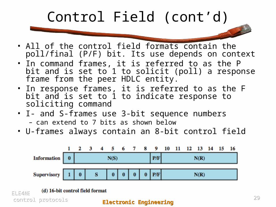
• All of the control field formats contain the poll/final (P/F) bit. Its use depends on context
• In command frames, it is referred to as the P bit and is set to 1 to solicit (poll) a response frame from the peer HDLC entity.
• In response frames, it is referred to as the F bit and is set to 1 to indicate response to soliciting command
• I- and S-frames use 3-bit sequence numbers– can extend to 7 bits as shown below
• U-frames always contain an 8-bit control field

3030Electronic EngineeringElectronic Engineering
ELE4NET: Data link control ELE4NET: Data link control protocolsprotocols
Information & FCS Fields
• Information Field – Only present in I-frames and some U-frames– Can contain any sequence of bits but must consist of an
integral number of octets– The length of the information field is variable up to
some system-defined maximum
• FCS (Frame Check Sequence) Field– FCS is an error-detecting code calculated from the
remaining bits of the frame, exclusive of flags– Either 16-bit CRC-CCITT or 32-bit FCS using CRC-32
is used

3131Electronic EngineeringElectronic Engineering
ELE4NET: Data link control ELE4NET: Data link control protocolsprotocols
HDLC Operation• HDLC operation consists of the exchange of I-frames, S-frames and
U-frames between two stations. • The operation of HDLC involves three phases:
– Initialization• One side or another initializes the data link. Set data transfer mode (NRM,
ABM or ARM) & length of sequence number (3 or 7 bits)
– Data transfer• After initialization, both sides may begin to send user data in I-frames,
starting with sequence number 0. The N(S) and N(R) fields of the I-frame are sequence numbers that support flow and error control
• S-frames are also used for flow and error control. The receive ready (RR) frame acknowledges the last I-frame received by indicating the next I-frame expected. Receive not ready (RNR) acknowledges an I-frame, as with RR, but also asks the peer entity to suspend transmission of I-frames. When again ready, it sends an RR. REJ initiates the go-back-N ARQ. It indicates that the last I-frame received has been rejected and that retransmission of all I-frames beginning with number N(R) is required. Selective reject (SREJ) is used to request retransmission of just a single frame
– Disconnect • One of the two sides signals the termination of the operation, either on its
own initiative if there is some sort of fault, or at the request of its higher-layer user

3232Electronic EngineeringElectronic Engineering
ELE4NET: Data link control ELE4NET: Data link control protocolsprotocols
HDLC Commands
& Responses

3333Electronic EngineeringElectronic Engineering
ELE4NET: Data link control ELE4NET: Data link control protocolsprotocols
HDLC Operation Example

3434Electronic EngineeringElectronic Engineering
ELE4NET: Data link control ELE4NET: Data link control protocolsprotocols
HDLC Operation Example (cont’d)