Embed Size (px)
Citation preview

13 - 1
INS
©NAR and TFHS
13 INERTIAL NAVIGATION SYSTEMS
(INS)
13.1 Principles and practical applicationThe system is capable of providing Great Circle navigation information worldwidewithout the need to communicate in any way with any external sources of informa-tion; so it neither transmits nor receives any signals. However, external sourceslike VOR, DME, ADF and GPS can be used as a reference when updating the INSposition. INS is often the primary and sometimes the only long-range navigationalsystem in use onboard aircraft on intercontinental, transoceanic or polar flights.
After being supplied with latitude and longitude of the ramp position prior todeparture, INS is capable of continuously updating extremely accurate displaysof: position, ground speed, attitude, and heading. If TAS information is put intothe system, it will also provide W/V information. In addition, it provides guidanceor steering information for the autopilot and flight instruments.
An Inertial Navigation System (INS) is able to provide world widenavigation without any communication to or from the aircraft.
The basic principle of inertial navigation is the measurement of acceleration andprocessing the acceleration information in a computer. Aircraft movements rela-tive to the Earth are sensed by accelerometers mounted on a gyroscopically con-trolled reference platform. The associated computer receives the signals from theaccelerometers via integrators, compares them with a timing signal and finallymakes a mathematical calculation to determine the present position of the air-craft.

General Navigation
13 - 2 ©NAR and TFHS
Figure: NV 13.1a
The platform is kept level and aligned to true north by a gimbal system stabilisedby gyroscopes and a platform control unit.
Furthermore, the basis of inertial navigation lies in the three laws of Newton:
1) A body continues in a state of rest, or maintain a straight line of movement,unless acted upon by an external force.
2) The acceleration of a body is directly proportional to the sum of the forcesacting on the body.
3) For every action, there is an equal and opposite reaction.
The main components of an INS are:
• the inertial navigation unit (INU) - which consists of:- the inertial reference unit (IRU)- the digital computer unit (DCU)
• the battery unit
• Mode selector unit (MSU)
• Control display unit (CDU)

13 - 3
INS
©NAR and TFHS
Figure: NV 13.1
First, let’s take a closer look at the inertial navigation unit (INU).
The four basic components of the INU are:
• A stable platform oriented to maintain the accelerometers horizontal to theEarth and to provide azimuth orientation.
• The accelerometers arranged on the stable platform to supply specificcomponents of acceleration.
• The integrators to receive the output from the accelerometers and to furnishvelocity and distance.
• A computer to receive the signals from the integrators and to change thedistance travelled into latitude and longitude.
Figure: NV 13.2
General Navigation
13 - 4 ©NAR and TFHS
The gyros in the inertial reference unit (IRU) supply attitude and heading informa-tion used to stabilise the weather antenna, and also fed to the autopilot (AFCS).Should the IRU fail, the normal attitude and heading gyros will automatically takeover the latter mentioned tasks.
After this brief introduction it is time to take a closer look at the components ofthe system and their principles.
An INS determines the heading and attitude by means of gyros orLaser Gyros, and calculates track made good and distance flownbased on information from accelerometers.
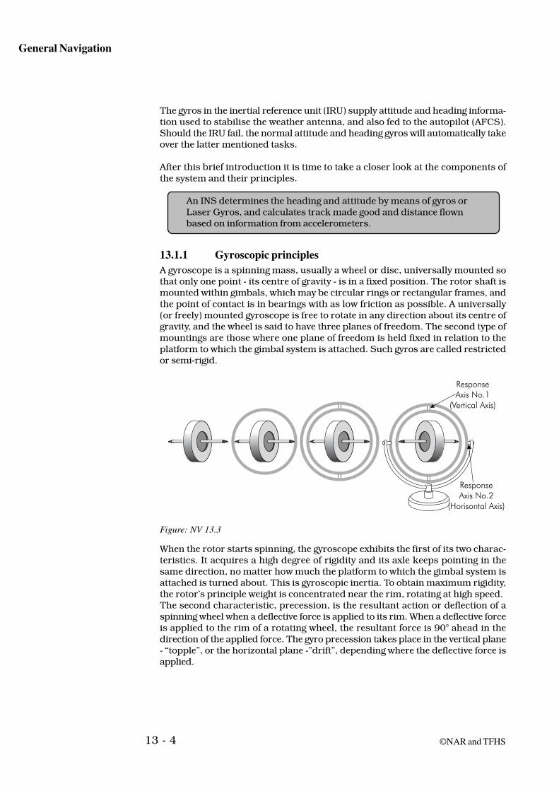
13.1.1 Gyroscopic principlesA gyroscope is a spinning mass, usually a wheel or disc, universally mounted sothat only one point - its centre of gravity - is in a fixed position. The rotor shaft ismounted within gimbals, which may be circular rings or rectangular frames, andthe point of contact is in bearings with as low friction as possible. A universally(or freely) mounted gyroscope is free to rotate in any direction about its centre ofgravity, and the wheel is said to have three planes of freedom. The second type ofmountings are those where one plane of freedom is held fixed in relation to theplatform to which the gimbal system is attached. Such gyros are called restrictedor semi-rigid.
Figure: NV 13.3
When the rotor starts spinning, the gyroscope exhibits the first of its two charac-teristics. It acquires a high degree of rigidity and its axle keeps pointing in thesame direction, no matter how much the platform to which the gimbal system isattached is turned about. This is gyroscopic inertia. To obtain maximum rigidity,the rotor’s principle weight is concentrated near the rim, rotating at high speed.The second characteristic, precession, is the resultant action or deflection of aspinning wheel when a deflective force is applied to its rim. When a deflective forceis applied to the rim of a rotating wheel, the resultant force is 90° ahead in thedirection of the applied force. The gyro precession takes place in the vertical plane- “topple”, or the horizontal plane -”drift”, depending where the deflective force isapplied.

13 - 5
INS
©NAR and TFHS
Gyroscopes are used in inertial reference systems for two reasons:
• To keep the accelerometers aligned horizontally with the surface of the Earthas the attitude of the aircraft changes,
• To make sure that the stable platform is kept aligned vertically with theEarth as the aircraft changes location, and as the Earth itself rotates.
In an INS the local Horizon and true north direction is sensed bymeans of three gyros and their apparent drift and topple causedby the rotation of the Earth.
13.1.2 Accelerometer principlesThe basic principles upon which the accelerometers operate are related to New-tons 3 laws regarding motion.
In aircraft systems the accelerometers are usually mounted with their input axesaligned with north and east, and this alignment must be maintained if the correctaccelerations are to be measured. Moreover the sensitive axes must be kept per-pendicular to the gravity vertical, otherwise, the accelerometers sense part of thegravity acceleration.
An accelerometer is an essential part of all inertial systems. There are today manyvarieties of this instrument, but they all work on the same basic principle. Theycan detect accelerations to thousandths of a G-force, far more sensitive than thehuman body can detect. In its simplest form, an accelerometer consists of a smallweight suspended between two springs, with an electrical pick-off which convertsthe compression of one of the supporting springs into an output signal.

General Navigation
13 - 6 ©NAR and TFHS
Figure: NV 13.4
The accelerometer cannot calculate velocity or distance itself, it quite simply regis-ters the spring displacement, which is directly proportional to the accelerating ordecelerating forces. Velocity and distance are computed from sensed accelerationby the application of basic mathematic formulas of integration. The relationshipbetween acceleration, velocity and displacement is shown in figure NV 13.5.

13 - 7
INS
©NAR and TFHS
Figure: NV 13.5
Note that velocity changes whenever acceleration exists and remains constant whenacceleration is zero.
In an inertial navigation system, two or three accelerometers are used. One willmeasure the aircraft’s accelerations in the North-South directions, another willmeasure the aircraft’s accelerations in the East-West directions. The third acceler-ometer will measure vertical displacement, but is not part of the system describedbelow. A North/South and East/West - orientation of the accelerometers is mostcommon, but especially for polar navigation another reference might be used.
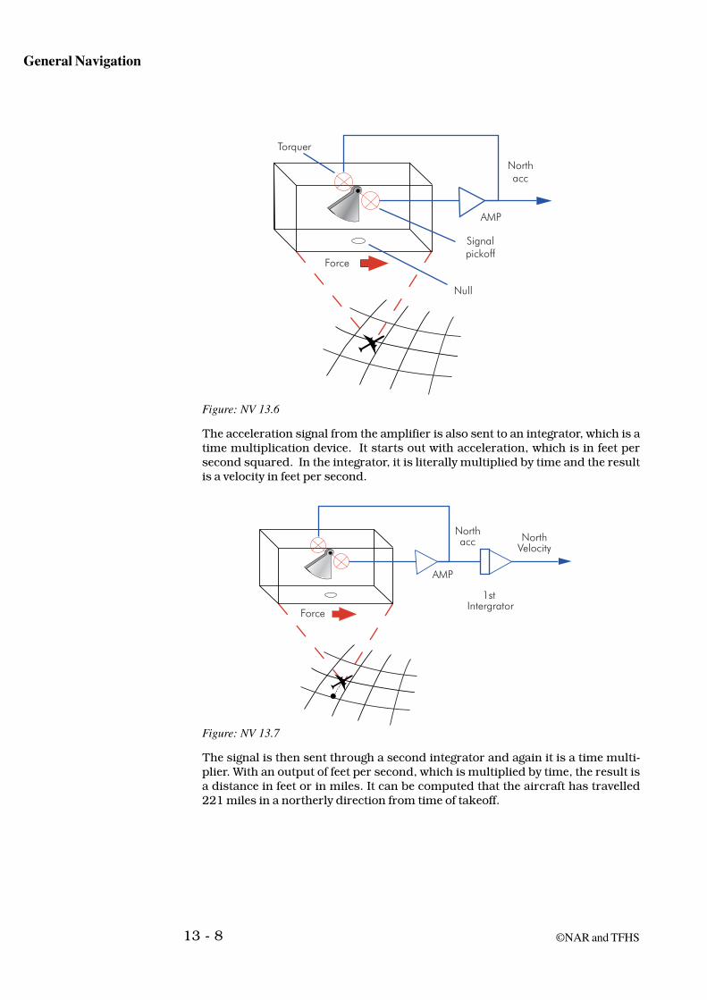
An alternative form of accelerometer uses a pendulum, in which case the displace-ment increments are angular rather than linear. When the aircraft accelerates, thependulum, due to inertia, swings off its null position. A signal pick-off device tellshow far the pendulum is off the null position. The signal from the pick-off device issent to an amplifier, and current from the amplifier is sent back into the acceler-ometer to the torque motor. The torque motor will restore the pendulum back toits null position. This is known as a “Force Re-balance” System.
General Navigation
13 - 8 ©NAR and TFHS
Figure: NV 13.6
The acceleration signal from the amplifier is also sent to an integrator, which is atime multiplication device. It starts out with acceleration, which is in feet persecond squared. In the integrator, it is literally multiplied by time and the resultis a velocity in feet per second.
Figure: NV 13.7
The signal is then sent through a second integrator and again it is a time multi-plier. With an output of feet per second, which is multiplied by time, the result isa distance in feet or in miles. It can be computed that the aircraft has travelled221 miles in a northerly direction from time of takeoff.

13 - 9
INS
©NAR and TFHS
Figure: NV 13.8
The computer associated with the inertial system knows the latitude and thelongitude of the takeoff point and calculates that the aircraft has travelled so far ina North-South direction and so far in an East-West direction. It now becomessimple for a digital computer to continuously compute the new present position ofthe aircraft.
13.1.3 Integrator principlesAll an integrator does is to produce an output which is the mathematical integralof the input, or in other words, the input signal multiplied by the time it waspresent.
From elementary calculus, displacement, velocity and acceleration are related asshown below.
x = ∫ vdt = ∫ ∫ a dt dt x = displacement v = velocity
The expression shows that we have to integrate the measured acceleration twice inorder to get the displacement.
Figure: NV 13.9

General Navigation
13 - 10 ©NAR and TFHS
The electrical output of each accelerometer will define the magnitude and directionof the acceleration vector. The two acceleration signals received by the integratorare by the first integration converted to aircraft velocity (v). The second integrationyields distance travelled (S).
13.1.4 The PlatformThe platform provides the mounting for the accelerometers and gyroscopes, andkeeps them level and aligned to the earth’s North/South and East/West axes. If theplatform is misaligned and accelerated in a North/South direction, the north sen-sitive accelerometer will not detect the full acceleration and the east accelerometerwill detect an unwanted component.
If the two accelerometers within an INS that are meant to measure accelerationsin the horizontal plane were fixed directly to the aircraft, their output would beaffected by the aircraft’s attitude so as to give false indications of accelerations.The solution to this problem is to keep the accelerometers level at all times bymounting them on a gyro stabilised platform that maintains its vertical alignmenteven if the aircraft is in a climb, a dive or rolling into a turn. The inner element ofthe platform where the accelerometers are mounted will also mount the gyroscopesused to stabilise the platform.
The accelerometers of an INS sense change of speed in the directionthe accelerometer is aligned with. This change in speed is integratedwith time to give velocity, and integrated another time to give distance.This integration process is completed several hundred times a second,and will thus give a nearly continuous information on distance travelledin the direction the particular accelerometer is aligned with(North/South, East/West and Vertical).
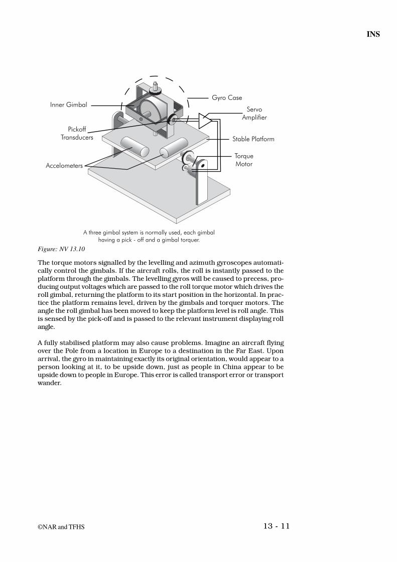
Pick-off transducers are used to register the movement of the gyro inner gimbal,and the output of the transducers is fed to a servo amplifier and motor, whichcontrol the gimbals of the platform and maintains the platform in a level position.The pick-offs are also used to provide pitch, roll and heading information to themain flight instruments.
13 - 11
INS
©NAR and TFHS
Figure: NV 13.10
The torque motors signalled by the levelling and azimuth gyroscopes automati-cally control the gimbals. If the aircraft rolls, the roll is instantly passed to theplatform through the gimbals. The levelling gyros will be caused to precess, pro-ducing output voltages which are passed to the roll torque motor which drives theroll gimbal, returning the platform to its start position in the horizontal. In prac-tice the platform remains level, driven by the gimbals and torquer motors. Theangle the roll gimbal has been moved to keep the platform level is roll angle. Thisis sensed by the pick-off and is passed to the relevant instrument displaying rollangle.
A fully stabilised platform may also cause problems. Imagine an aircraft flyingover the Pole from a location in Europe to a destination in the Far East. Uponarrival, the gyro in maintaining exactly its original orientation, would appear to aperson looking at it, to be upside down, just as people in China appear to beupside down to people in Europe. This error is called transport error or transportwander.

General Navigation
13 - 12 ©NAR and TFHS
Figure: NV 13.11
There is obviously a need for the gyro stabilised platform to be corrected so that itwill remain oriented to local vertical and not to original vertical as the aircraftparallels the surface of the Earth on its way to the destination.
Even when the aircraft is parked on the ground, the gyro will appear to tilt as timegoes on. This is due to the rotation of the Earth at the rate of 15° per hour, whichthe gyro is not able to distinguish from a change in the attitude of the aircraft.Imagine a gyro on the North Pole with its spin axis oriented horizontally. After onehour, the gyro appears to have drifted 15° to the right.
The same gyro on the equator with its spin axis horizontally and parallel to ameridian, will on the other hand remain parallel to the meridian as the Earthturns through 15°. This error is called apparent wander drift, and is as explainedabove, 0° at the equator and equal to 15° per hour at the Poles. At any otherlatitude, the drift can be calculated as 15° per hour x sine latitude. The process ofcorrecting for all extraneous gyro factors is called “torquing”.
Figure: NV 13.12

13 - 13
INS
©NAR and TFHS
The INS maintains the stable platform in a level attitude and aligned with truenorth by continually applying corrections for transport wander and apparent wan-der to the torque motors. When considering a stationary platform, the correctionsfor apparent wander drift is relatively easy to visualise. The corrections due totransport wander are related mathematically to the radius of the earth, a factdiscovered by Dr Schuler in 1923 when studying the inaccuracies of gyro basedshipbourne heading reference systems. A gyro stabilised platform that is correctedfor drift due to transport wander and earth rotation is said to be “Schuler Tuned”.
Accelerometer and integrator errors produce total system errors in attitude anddistance measurement, which are oscillatory. Errors in levelling of the platformwill also produce oscillatory errors. For example if the accelerometer is measuringa voltage which results in a +5nm system error this error will be zeroed after 21minutes, increase to -5nm after 42 minutes, be zeroed again after 63 minutes andincrease to +5nm after 84 minutes. These errors are said to be bounded; they arebounded by the amount of the initial error. Errors in the gyroscopes, namely gyrodrift and azimuth gyro misalignment, are not bounded. They produce errors thatincrease rapidly with time. In order to reduce system errors to a minimum, lowdrift gyros are used with very accurate levelling and alignment of the platformbeing made prior to take off. Levelling and alignment are most important to thecorrect operation of the system. Correct levelling reduces bounded errors to aminimum, with accurate alignment reducing unbounded errors.
13.1.5 Schuler tuned platformPlatform stability is critical to overall system accuracy, and a slight error in main-taining the horizontal would induce a major error in distance computations. In1923 a German engineer (Dr Maximillian Schuler) devised a method which nowa-days is used to solve the problem of eliminating inadvertent acceleration errors.
The Schuler pendulum is an imaginary pendulum with length equal to the Earth’sradius. It is suspended from the surface of the Earth so that the pendulum bob isat the centre of the Earth, the pendulum indicating the local vertical. If the pendu-lum bob is moved away from the Earth’s centre by an external force, the pendulumwill start to swing back and forth.
The time for one complete oscillation is about 84 minutes. As a consequence, theplatform from which a pendulum with the Schuler frequency is suspended willoscillate about the local vertical at a rate of 0.071° per second.

General Navigation
13 - 14 ©NAR and TFHS
Figure: NV 13.13
On the other hand, if the suspension point on the surface of the Earth is moved oraccelerated, it has no affect on the pendulum - it will not be moved away from thecentre of the Earth, and thus it will always lie along the local vertical, irrespectiveof accelerations which attempt to take it out of that vertical.
If the principle of the Schuler pendulum is applied to the gyro platform, and thesystem is behaving like an 84-minute pendulum, it will continuously seek out thetrue vertical. The output of the first integrator, which is proportional to aircraftvelocity, is used to rotate the platform containing the accelerometers at a rate,which is identical to the angular velocity of the aircraft moving over the Earth. Forexample, without this compensation an INS flying from some position to a pointon the other side of the Earth would mistakenly report that it is upside downwhen it arrives.
So, like the Schuler pendulum, the INS will seek out the local vertical and main-tain or oscillate about this position despite accelerations or motions of the air-craft.
13.1.6 Navigation computerThe computer calculates the aircraft’s position and velocity from the signals re-ceived from the two horizontal accelerometers (via the integrators). The secondfunction of the computer is to calculate the gyro precession signals, which are sentas correction signal to the stabilised platform.
When the computer is turned on, present position of the aircraft must be insertedto establish the starting position and to ensure that the platform has the correctinitial orientation relative to the Earth. When the system is aligned, and the lati-tude and longitude of the destination as well as waypoints enroute have beeninserted, the system is capable of providing information on navigation parameterssuch as:• True Track • Drift Angle • Present Position• Groundspeed • Cross Track Distance (XTK) • Time to select ed waypoint• True Heading • Track Angle Error (TKE) • Desired Track Angle (DSRTK)
If the computer is supplied with TAS, it will also provide W/V - information.

13 - 15
INS
©NAR and TFHS
Figure: NV 13.14
The INS computed data may in addition be displayed on some of the cockpitindicators, normally the Flight Director and Horizontal Situation Indicator.
Due to redundancy-requirements, dual or triple INS installations are commonlyseen onboard aircraft operating on long range flights.
13.1.7 Strapdown Systems (IRS)The IRS (Strapdown Inertial Reference System) is a system that is becoming morewidely used. It provides aircraft with flight information without the need for gim-bals, bearings, torque motors or other moving parts.
The system utilises inertial sensors that are mounted solidly to the system chas-sis, which is in turn mounted solidly to the aircraft. These sensors consist of upto three ring laser gyros and three accelerometers that replace the conventionalmechanical gyros and compass systems. These sensors, coupled with high-speedmicroprocessors, allow the system to maintain a stable platform reference math-ematically, rather than mechanically.
This result is a significant increase in accuracy and reliability over older, gimballedstabilised platforms.
Because the system pitches, rolls and yaws with the aircraft, the accelerometersare mounted in such a way that the input axis of one accelerometer is always inthe longitudinal aircraft axis, one is in the lateral axis, and one is in the verticalaxis. Likewise, the gyros are mounted in such a way that one gyro senses roll, onesenses pitch, and the other senses yaw.
The IRSs are the airplane’s sole source of attitude and heading information, ex-cept for the standby attitude indicator and standby magnetic compass. In theirnormal navigation mode, the IRSs provide attitude, true and magnetic heading,acceleration, vertical speed, ground speed, track, present position, and wind datato appropriate airplane systems.
To provide complete information on the aircraft movements in space,three accelerometers are required, each one aligned at 90° to the other.The three accelerometers may be aligned N/S, E/W and vertically, or bealigned with the aircrafts three axis, as in a “strap down system”.

General Navigation
13 - 16 ©NAR and TFHS
Laser GyroThe laser gyro is a device which measures rotation by using the properties of twolaser beams rotating in opposite directions inside a cavity. The operation of alaser gyro is founded on the effects the rotational motion has on the two laserbeams. In fact, laser gyros are not gyros at all, but sensors of angular rate ofrotation about a single axis. If you are already well acquainted with the Dopplerprinciple you will find that the operation of the Laser “gyro” has much in commonwith the use of the Doppler effect to find relative speed.
In a laser gyro two beams of light are generated, each travelling around the cavity(in this case a triangle) in opposite directions. One beam travels in a clockwisedirection and the other travels in a counterclockwise direction. The beams areoperated by two lasers, mounted inside a triangle of three tubes made of a specialglass. The tubes have two holes drilled down their length, which are filled withhelium neon gas. A DC voltage is applied across the cavity, which excites the elec-trons in the gas to resonate at a given frequency and lase. Each hole provides apath for its “own” laser, and the two laser beams travel in opposite directionsround the tubes.
The laser frequency/wavelength is matched to the dimensions of the tubes (bothlength and ares) so as to achieve a resonant structure. This structure/laser com-bination operates at a known resonant frequency. The beams are reflected offmirrors at each corner so that the beams can go on down the next arm.
The mirrors serve as both reflectors and optical filters, reflecting the light fre-quency for which they were designed and absorbing all others. One mirror is servoadjusted to maintain a constant physical distance around the ring. A partiallysilvered mirror is mounted at one corner, and a percentage of each beam escapesto strike a detector. You will note from the diagram that one of the exciting beamsis reflected via a prism and then off a mirrored surface so that it can meet andinterfere with the other beam as it strikes the photoelectric cells. The interferingbeams cancel and reinforce one another, creating a fringe pattern.
Figure: NV 13.15

13 - 17
INS
©NAR and TFHS
The light frequency can be varied somewhat by changing the path length over whichthe waves have to travel. For a given path length there are an integral number ofwaves (cycles which occur over the complete path). If the path length is altered,the waves will be either compressed or expanded, but there always will be anintegral number of cycles which occur over the complete path. If the waves arecompressed, more cycles occur per unit time. Hence, the frequency increases. Ifexpanded, the opposite is true.
Since both contra-rotating beams travel at the same constant speed (speed oflight), it takes each the same exact time to complete its circuit. However, if the gyrowere rotated on its axis, the path length of one beam would be shortened, whilethat for the other would be lengthened.
For a better understanding, consider a particle of light, a photon, just leaving thecathode and travelling toward the mirror on the right-hand corner. If the gyroturns clockwise on its axis, the mirror would move closer to the photon whichwas on its way. Since, as explained, the laser beam adjusts its wavelength for thelength of the path, the beam travelling the shorter distance would rise in frequency(wavelength decreases), while the beam travelling the longer distance to completethe circuit would encounter a frequency decrease. This frequency difference be-tween the two beams is directly proportional to the angular rate of turn about thegyro’s axis. Simply stated, that is the principle of the laser gyro.
The difference in frequency in the laser gyro is measured by an optical detectorwhich counts the fringes of the fringe pattern generated by the interference of thetwo light waves. One of the two photocells indicates in which direction the fringesare moving, which again is an indication of whether the gyro is rotating to the leftor right. The other photocell indicates the speed of rotation.
Figure: NV 13.16
ErrorsThe length of the optical path influences accuracy of a laser gyro. The longer the path,the higher the accuracy. The relationship is not linear. For example, a small increasein path length makes for a larger increase in accuracy. As with spinning wheel gyros,the major source of error in a laser gyro is random drift. While in spinning wheel

General Navigation
13 - 18 ©NAR and TFHS
gyros the root cause is imperfect bearings and mass imbalances, in the laser types itis noise, due almost exclusively to imperfect mirrors including mirror coatings.
The greatest advantage in accuracy is gained by increasing the size of small sys-tems. A path length of 30cm is considered acceptable in terms of accuracy. Mostring lasers are triangular because they offer an overall advantage over other lay-outs.
Ring lasers are subject to random drift due to noise, almost entirely due to imper-fect mirrors and coatings.
Phase lock is a phenomenon where the two lasers can lock in phase at smallangular rates of rotation. The “Dither Motor” causes the ring laser gyro to vibrate,at 319Hz, thus enabling the problem of “phase lock” to be avoided. This is sensedby the optical read out as a frequency change first in one direction and then in theopposite direction. The frequency changes cancel each other out bur do not pre-vent the laser ‘lock’ phenomenon.
Size/Weight: The ring laser gyro is small (hand palm size) and light (2.3 lbs).
Advantages and Disadvantages of Ring Laser GyrosAdvantages:
High reliabilityHigh accuracyLow life-cycle costVery low ‘g’ sensitivityDigital outputLow power requirementNo run-up (warm-up) period
Disadvantages:High capital cost
AccelerometersThe accelerometer produces an output proportional to the acceleration appliedalong the sensor’s input axis. The microprocessor integrates the acceleration sig-nal to calculate a velocity. Integration is a function that can be viewed as a multipli-cation by time. For example, a vehicle accelerating at three feet per second squaredwould be travelling at a velocity of 30 feet per second after 10 seconds have passed.Note that acceleration was simply multiplied by time to get a velocity. The micro-processor also integrates the calculated velocity to determine position. For exam-ple, a vehicle travelling at a velocity of 30 feet per second for 10 seconds will havechanged position by 300 feet. Velocity was simply multiplied by time to determinethe position.
The output of the gyros of aircraft pitch, roll and yaw will enable the computer toconvert the outputs of the accelerometers into North/South, East/West and verti-cal components. So if a gyro measured a yaw rate of 3° per sec for 30 sec, theaircraft’s heading will have changed by 90°.

13 - 19
INS
©NAR and TFHS
Take the following example:Consider a platform that measures an initial heading of 090°, a pitch of 10°, zerodegrees of roll angle, and only a longitudinal acceleration. The pitch indicates thatthe acceleration is partially upwards as well as eastwards, and so the computerresolves it into a local vertical acceleration and an eastward component. The verti-cal component is integrated to give a vertical speed (and this is then displayed), asecond integration yields a change in altitude. The eastward component is inte-grated to produce an easterly velocity, and then integrated again to give departure(and then to change of longitude)
It is of interest that it has not been considered economically viable to improve theaccuracy of either the accelerometers or the integrators from those used in theearlier generation systems. However, the “Automatic Calibration” discussed lateron helps to overcome constant value errors.
In addition to the basic strapdown concepts that have been discussed, there aresome additional details which must be considered in order to navigate with re-spect to the Earth’s surface. The Earth’s gravity, rotation, and shape necessitatethese special considerations. A strapdown IRS compensates for these special ef-fects with the microprocessor’s software entirely, as described below.
GravityVertical velocity and altitude are calculated using the acceleration that is meas-ured perpendicular to the Earth’s surface. However, an inertial accelerometer can-not distinguish between gravitational force and actual aircraft acceleration. Con-sequently, any accelerometer that is not perfectly parallel to the Earth’s surfacewill measure a component of the Earth’s gravity in addition to the true aircraftacceleration. Therefore, the IRS’s microprocessor must subtract the estimatedlocal gravity from the measured vertical acceleration signal in order to calculatethe vertical speed and new altitude.This prevents the system from interpreting gravitational force as upward aircraftacceleration.
Earths RotationAs discussed previously, the purpose of the gyros is to measure rotational motionof the aircraft with respect to the Earth. However, the laser gyro in a strapdownconfiguration inherently measures movement of the aircraft with respect to iner-tial space. Another way of looking at this is that the gyros measure the motion ofthe aircraft with respect to the Earth, plus the motion of the Earth with respect toinertial space.
The Earth rotates with respect to inertial space at a rate of one rotation per 24hours as it spins from West to East on its own axis, plus one rotation per year asit revolves around the sun. The sum of these two rates is equivalent to an angularrate of 15.04 degrees per hour. The microprocessor compensates for this rate bysubtracting this value, which is stored in memory, from the signal measured bywhichever gyro or gyros are pointed eastward. Without this “earth rate” compen-sation, an IRS operating at the Equator would mistakenly think that it is upsidedown after 12 hours of navigation. At other places on the Earth, the system woulddevelop similar errors in pitch, roll, and heading.

General Navigation
13 - 20 ©NAR and TFHS
The computer therefore will calculate the effect of both drift and topple due to theearth’s rotation at the present position.
Earths Spherical ShapeThe major effect imposed by the Earth’s spherical shape is somewhat similar tothat caused by the Earth’s rotation. As an aircraft travels across the surface of theEarth, its path becomes an arc due to the shape of the Earth. Consequently, thegyros - particularly the pitch axis gyro - measure a rotational rate, because travel-ling in a curved path always involves rotation. This rate, called the transport rate,does not describe rotational motion of the aircraft with respect to the Earth’ssurface. Therefore, the IRS must calculate how much transport rate is beingmeasured by the gyros, and subtract that value from their measurements.
There are many other effects that are compensated for in commercial inertial ref-erence systems, and even more in systems used in military applications. Theseeffects have not been considered here because they get more and more complicatedas higher precision is demanded, yet knowledge of them does not appreciablyincrease understanding of strapdown navigation principles.
Schuler TuningThe strapdown platform is still subject to the “Schuler Loop”, and one should beaware of the 84.4 minute period of oscillation should an error be generated (usu-ally at first integrator level).
Automatic CalibrationAutomatic Calibration uses computer programmes to estimate the long-term driftin the sensors, and adjust the sensor calibration coefficient accordingly. The gyrosand the accelerometers use separate routines to determine the drift, or “bias”. Theaccelerometer bias errors are calculated during taxi, working on the assumptionthat you taxi forwards, not sideways, and so any indicated velocity out of thelateral accelerometer must be an error. The longitudinal accelerometer bias errorwill also be induced in (equivalent to infect) the lateral accelerometer during align-ment. So by examining the headings used by the aircraft to taxi out, the computercan deduce the bias error in the longitudinal accelerometer. Outputs from thevertical accelerometer during taxi represent a bias error.
Alignment of IRSThere is no requirement to level a strapdown IRS, and so the output of the threegyros when the aircraft is stationary can only be due to the earth’s rotation. Thecomputer uses this to calculate the bearing of true north. During this time, thecomputer will compare the latitude inserted by the crew with the one calculatedfrom the perceived earth rotation. The crew will need to initialise the system byinserting latitude and longitude, this may be done at any time during the align-ment.
If there is a discrepancy between inserted position and either the computed posi-tion or the last position on shutdown, the MSU ALIGN light on the control panelwill flash. The correct latitude must be entered or the system will not allow theNav mode to be entered. If the mode selector is put to NAV from OFF, the systemwill automatically enter NAV as soon as alignment is complete (the above checkpermitting). Nav must be selected prior to moving the aircraft. Normal levels of

13 - 21
INS
©NAR and TFHS
vibration due to loading and wind gust do not affect alignment. Should excessivemotion be experienced whilst the system is held in ALIGN, the system will need tohave power removed for 3 seconds before alignment can be restarted.
The aircraft must remain stationary during alignment.
Normal IRS alignment, between approximately 70°N and 70°S, takes about 10minutes, while high latitude alignment at latitudes between 70° and 78° takes upto 15-20 minutes.
Magnetic variation between 73° North and 60° South latitudes is stored in eachIRS memory. The data corresponding to the present position are combined withtrue heading to determine magnetic heading. If magnetic information is unavail-able, special navigation equipment is required to provide true heading to the EHSIs.
Fast realignment (on the ground)During transit or through—flight stops with brief ground times, a thirty—secondrealignment and zeroing of ground speed error may be performed by selectingALIGN from NAV while the airplane is parked. Present position should be simul-taneously updated by manually entering Latitude and Longitude prior to reselectingNAV.
NOTE: If the airplane is moved during alignment or fast realignment (ALIGNlight illuminated), the IRSs automatically begin the full 10—minutealignment process over again.
Traditional gyros need a long time for warm-up before reaching themost stable operating conditions. These gyros also often have a verynoticeable drift. The drift error is accumulative with time, and mayduring long flights become unacceptable high, calling for a re-alignmentin flight.
A laser gyro does not need a long warm-up time, and the drift is verysmall. Laser gyros have therefore replaced traditional gyros inairborne INS.
Loss of AlignmentIf an IRS loses both AC and DC power, the alignment is lost. Alignment can also belost if the Mode Selector is moved out of the NAV position.
If alignment is lost in flight, the navigation mode (including present position andground speed outputs) is inoperative for the remainder of the flight. However,selecting ATT allows the attitude mode to be used to relevel the system and pro-vide ADI attitude. The attitude mode requires approximately thirty seconds ofstraight and level unaccelerated flight to complete the releveling. Some attitudeerrors may occur during acceleration, but will be slowly removed after accelera-tion.
The attitude mode can also provide heading information, but to establish com-pass synchronization the crew must manually enter the initial magnetic heading.

General Navigation
13 - 22 ©NAR and TFHS
Thereafter, drift of the IRS heading will occur (up to 15° per hour). Therefore,when in the ATT mode, an operating compass system must be periodically cross—checked and an updated magnetic heading entered in the IRS, as required.
IRS Control PanelManual IRS entries of present position or magnetic heading are normally accom-plished on the P0S INIT page of the FMC/CDU. If desired, the IRS Display Unitmay also be used.
Figure: NV 13.16b
The IRS system control knob has the following positions:
OFF - the system is turned offALIGN - the system is in alignment mode upNAV - the system is in navigation modeATT - the system is used for attitude information only
The display selector on this system has the following functions:
TK/GS - track and ground speed is displayedPPOS - present position is displayedWIND - wind at present position is displayed, often referred to as spot windHDG - heading is displayed
13.1.8 Accuracy, reliability, errors and coverageInertial navigation systems have excellent reliability and present position errors ofless than 1NM per hour is common in commercial aircraft. However the error iscumulative, so that the accuracy degrades with time. The performance can beimproved during flight if the system is updated by making a position fix when anaccurate present position reference is available.

13 - 23
INS
©NAR and TFHS
Furthermore, the accuracy depends fully on the accuracy of the initial latitude andlongitude that is inserted during system start up. Therefore, system alignment isof paramount importance.
Accelerometer and integrator errors produce total system errors in attitude anddistance measurement, which are oscillatory. Errors in levelling of the platformwill also produce oscillatory errors. For example if the accelerometer is measuringa voltage which results in a +5nm system error this error will be zeroed after 21minutes, increase to -5nm after 42 minutes, be zeroed again after 63 minutes andincrease to +5nm after 84 minutes. These errors are said to be bounded: they arebounded by the amount of the initial error. Errors in the gyroscopes, namely gyrodrift and azimuth gyro misalignment, are not bounded. They produce errors thatincrease rapid with time. In order to reduce system errors to a minimum, lowdrift gyros are used with very accurate levelling and alignment of the platformbeing made prior to take off. Levelling and alignment are most important to thecorrect operation of the system. Correct levelling reduces bound errors to a mini-mum, with accurate alignment reducing unbounded errors.
Since the system is independent of any external sensors, navigation informationis available all over the world and in all weathers.
13.1.9 Flight deck equipment and operation of INSINS computed data can be displayed on the Horizontal Situation Indicator (HSI)and on the INS Control/Display Unit (CDU). As part of a flight management sys-tem (FMS), INS data may also be displayed on the FMS display unit.
Mode Selector Unit (MSU)The MSU provides mode selection, and includes a NAV ready light and an emer-gency battery low level light.
The green NAV ready light illuminates when the system has reached the desiredalignment status for accurate navigation. The red BAT-light illuminates in case theINS has automatically shut down due to low battery power when operating on thebattery.
Figure: NV 13.17
The mode selector switch is marked OFF/STBY/ALIGN/NAV/ATT.
• The STBY position permits the system to warm up.
• The ALIGN position initiates the alignment procedure in the computer and al-lows for the operator to enter present position of the aircraft.

General Navigation
13 - 24 ©NAR and TFHS
• The NAV position is the normal navigation and reference position. May be se-lected after the NAV READY light is illuminated.
• The ATT position manually disables the nav function while retaining the atti-tude function. This position might be selected when long range area navigation isnot required, and will provide only inertial attitude and heading information.
Control Display Unit (CDU)The CDU is normally mounted on the control stand in the cockpit, and providescontrol of all the INS functions. Information from the selected functions is dis-played in the two upper windows. In place of the two-window read-out, a cathoderay tube (CRT) type is now becoming more common in commercial aircraft. ACDU is shown in the figure below.
Figure: NV 13.18
The keyboard is used to enter latitude and longitude in the alignment mode, andto enter flight plans using departure, waypoint, and destination lat/long coordi-nates. The function of the switches is shown below.

13 - 25
INS
©NAR and TFHS
ALERT-lightThe Alert light gives the operator a two minute warning (depending on aircraft fit)before the next selected waypoint is reached. If fitted, the Automatic Flight ControlSystem will make the heading change, the light will go out and the waypoint (FROM/TO) info will be amended.
BAT-lightIf the Amber Battery light illuminates the INS is operating on its standby batterypower. Batteries give between 15 and 30 minutes of normal operation. If batterycharge is below minimum the system will shut down and red BAT on MSU andred WARN on CDU will illuminate.
WARN-lightThe Warning illuminates a red light whenever the self-checking system in the com-puter detects an out of tolerance error. To establish which error requires the DSRTK/STS position selected to indicate the status of the system on the right-hand dis-play.
All INS equipment being installed in aircraft includes a navigationcomputer. The navigation computer is fed information from the currentflight plan. Airspace data such as routes, airfields and navigation aidsare permanently stored and regularly updated in the navigationcomputer.The cockpit crew communicate with the navigation computer by a CDU,and may enter or extract stored or processed data.
In aircraft where FMS is installed, data from the INS will be comparedand blended with data from other sources before selected for executionof the navigation. The cockpit crew will be kept informed on theoperational status of the different equipments, and may take action toexclude any equipment in case of abnormal operation or malfunction.
13.1.10 INS Alignment proceduresIt is very important that the stable platform is accurately levelled with respect tothe local vertical and aligned in azimuth with respect to True North after thesystem has been turned on. If the INS has a free azimuth system, another azi-muthal reference than True North might be used.
It is important that the aircraft is not moved during alignment.
The initialisation process is automatic provided that present position (ramp co-ordinates) is entered into the system. Most INSs have internal clock/calendarswhich, in addition, require that time and date information are verified. After theramp coordinates are entered, the alignment takes place until the “Nav Ready”light on the MSU comes on.

General Navigation
13 - 26 ©NAR and TFHS
Figure: NV 13.19
The time required for alignment of a typical system varies from two and a halfminutes at the Equator to a maximum of ten minutes at 70° latitude. The align-ment period will be longer the higher the latitude - and if mechanical gyros areused and the ambient temperature is low.
The alignment procedure is twofold: Azimuth alignment of the gyros to True North(gyro compassing), and platform orientation relative to the Earth (levelling).
Gyro-compassingDuring alignment the INS determines the local vertical and the direction to TrueNorth. The latter is called gyro compassing. This process makes use of the abilityof the gyros to sense the angular rate of the aircraft. Since the aircraft is stationaryduring alignment, the angular rate is due to earth rotation. The computer usesthis angular rate to determine the direction to True North. If the platform is mis-aligned in azimuth, the east gyro will see the wrong earth rate and will cause thenorth accelerometer to tilt. The output of this accelerometer is then used to torquethe azimuth and east gyro to ensure a true north alignment and a level condition.A True North reference is useless in the Polar Regions, but any other referencedirection is usable, provided that the precise relationship is known and that theINS computer is capable of calculating the coordinate transformation.
LevellingPrecise levelling of the stable element is accomplished prior to flight until theoutput from the accelerometers that measure acceleration in the horizontal planeis zero. The stable element is moved until the pendulum reads zero, indicatingthat the accelerometers are not measuring any component of gravity and that theplatform is level.Total time taken for alignment process is variable. For a gimballed INS up to 20minutes may be required with the aircraft stationary.

13 - 27
INS
©NAR and TFHS
For an IRS unit, the alignment procedure is much shorter (ten minutes or evenless) and some equipments do not even require the aeroplane to remain station-ary during the process.
Preflight Levelling and AlignmentSystem description has assumed that the platform has somehow been levelledand aligned. The process however is difficult to achieve and must be carried out ina series of pre-flight checks. The stages of levelling and alignment are controlled bymode selections made by the pilot on the Mode Selection Unit (MSU) shown be-low.These stages are:
a. Standby b. Alignc. Navigation d. Attitude Reference
Figure: NV 13.20
Before the STBY-position is selected on the MSU, and the switch is in the OFF-position, the platform is neither levelled nor aligned.
Figure: NV 13.21
Standby Mode (STBY)Selecting standby on the MSU switches power to the system and provides heatingto the gyros to achieve optimum operating temperatures. Coarse levelling and align-ment of the platform are also carried out automatically by synchro memory andgravity sense switches. In order that the platform remains level and aligned in thepresence of earth rotations, correct aircraft latitude and longitude must be in-serted to enable the correct correction terms to be generated by the platform con-trol unit. Base latitude and longitude is put into the nav computer through thecontrol display unit (CDU) by the pilot.

General Navigation
13 - 28 ©NAR and TFHS
When set to standby, the equipment carries out a self test following a fixed se-quence. As components are tested and found correct the system status is regis-tered and displayed. Status 01 shows that all components are working. Status200 shows that 200 components still have to be tested. Selecting the CDU toSTATUS can easily check the status. Once a status of about 90 has been achievedthe next mode ALIGN can be selected. The system should remain in STANDBY for3-4 minutes. During this time, route turning points can be inserted as waypoints.
Coarse AlignmentDuring the coarse alignment phase the platform is roughly levelled and aligned inazimuth thereby removing gross errors and reducing overall alignment time. Thistakes place in two steps in the warm up period in the STBY mode; first the plat-form is brought to local vertical.
Figure: NV 13.22
The second step includes pointing the platform initially toward magnetic north,so that resolving true north can be accomplished in less time during the finealignment.
Figure: NV 13.23
Align ModeThe ALIGN mode should be selected on the MSU after status 90 has been reachedin the BITE sequence. In this mode fine levelling and fine alignment are automati-cally provided.

13 - 29
INS
©NAR and TFHS
Fine LevellingFine levelling is achieved using an accelerometer null technique. In this mode it isassumed that the aircraft is stationary on the ground and that coarse levelling andalignment is complete. Both accelerometers are used to fine level the platform.When stationary there should be no output from the accelerometers. If the plat-form is tilted, however, there will be an output from the accelerometer due to acomponent of gravity being sensed. Error outputs from the North/South and East/West accelerometers are then used to drive the pitch and roll gimbals until theplatform is driven into the horizontal, at which time the accelerometer outputs arezeroed. This technique levels the platform to within 6 seconds of arc.
Fine Alignment or Gyro-Compassing.Gyro-compassing or fine azimuth alignment is the final stage of self alignment andis based on the fact that if the East gyro input axis is pointing East it will notsense any component of Earth rate. If it is misaligned however it will sense acomponent, and this sensed component can be used to align the platform. Twomain methods are employed: closed loop and open loop gyro-compassing.
a. Closed Loop Gyro-compassing. The sensed component of Earth rate willcause the platform to tilt out of level and so the North accelerometer sensesa component of gravity. The signal from the accelerometer is fed through ahigh gain amplifier in order to torque the platform in azimuth until theerror is nulled. The levelling loop continues to be operative during the gyro-compassing phase. Alignment in azimuth using this method should achievean accuracy of about 6 arc minutes in about 6 - 10 minutes.
b. Open Loop Gyro-compassing. The majority of modern North slaved INS useopen loop gyro-compassing. When the system is switched from thealignment to the navigate mode the platform is rotated through thecomputed misalignment angle. Although this would appear to be a quickermethod than the closed loop technique, in practice the error signal is smalland difficult to measure in the presence of noise. In order to overcome thisproblem the misalignment signal has to be filtered and averaged over time,usually about 7 minutes, and so in fact there is little difference in the tunetaken by each method.
The Earth rate sensed by a misaligned East gyro depends on the cosine of thelatitude and therefore gyro-compassing accuracy decreases with increasing lati-tude and cannot be achieved close to the poles. Furthermore the time taken toachieve alignment will increase with latitude due to the reducing strength of theerror signal. The accuracy of the alignment will also depend on the real drift rate ofthe East gyro as this will be an unwanted component of the error signal.
The platform is now aligned and this stage is now complete. The status of theBITE sequence will show 03 or less, indicating that NAV should be selected on theMSU. ALIGN must never be selected in flight as the accelerometer and gyroscopeoutputs are passed to different components than they would be in flight. In ALIGNthe accelerometers are routed to the levelling gyroscopes and not to the integra-tors, and the East/West gyroscope is routed to the azimuth gimbal torquer andnot to the pitch and roll gimbals as required in the NAV or flight mode.

General Navigation
13 - 30 ©NAR and TFHS
NAV ModeOnce the system has achieved alignment, the green “Ready” light will illuminateand the Nav mode should be selected. Once the system is fully in the Navigationmode, should the Mode Selector be inadvertently moved from Nav, the whole align-ment and levelling procedure must be recommenced before Nav can be reselected.Since this can only be achieved stationary on the ground, the INS would be ren-dered useless as a navigational aid if this were to happen in-flight. For this reason,the mode selector is normally sited away from the CDU and a safety device is fittedinto the control switch itself.
ATT REF (attitude reference mode)In the event that the system degrades, selection of ATT will only provide pitch, rolland platform heading outputs from the INS to the Auto Flight Control System(AFCS) and the radar stabilisation, with no navigation data. The CDU displaysonly status data or will be blank. However, this back-up system will, in the ATTmode, lose the alignment reference and therefore the NAV mode cannot (as alreadymentioned) be reset until back on the ground.
On selecting ATT, the aircraft may well have to be held straight and level for ashort period whilst the platform re-levels itself. The system is then subject toacceleration errors (like the A/H) and drifting of the indicated heading (like theDGI). Because the INS is not coupled to a Remote Indicating Compass the headingwill need to be updated periodically.
13.1.11 INS OperationIn controlling and operating the INS, the operator is able to store a great circlenavigation flight plan, update the flight plan prior to or during flight, and displaynavigation and guidance data relative to the stored flight plan.
Present position entryThe aircraft’s present position must be entered into the INS before the INS can bealigned. The MSU mode switch must be set to standby, and the display switch toPOS. By using the keyboard, the ramp position in degrees, minutes and tenths ofa minute is inserted. Any error in the entered position will be carried as a con-stant value during the whole flight, thus several techniques are used to avoidincorrect entries. One of the techniques is to have one of the crewmembers to readthe coordinates while another enters them, the former checking the inserted num-bers.
Waypoint coordinates entryThe waypoints coordinates may be entered during the alignment sequence whilethe aircraft is on the ground, or they may be entered after takeoff, but they shouldnot be entered until after present position coordinates have been entered. Onceentered, waypoints will remain in the INS until new waypoints are entered orsystem is turned off.
Waypoint 0 is reserved for the computer to establish a track from the aircraft’spresent position. If return to Point of Departure capability is being used, the pointof departure coordinates should be entered into waypoint 1.

13 - 31
INS
©NAR and TFHS
The following notes describe the way in which you should handle waypoints on a“typical” INS equipment. These procedures will differ slightly depending on theequipment being used.
Figure: NV 13.24

General Navigation
13 - 32 ©NAR and TFHS
Once all waypoints are entered, a double check using DIST/TIME should be madeagainst the Flight Plan to ensure there are no errors.
Flight plan changesA change in the programmed flight plan may be performed both prior to, and inflight by changing or adding waypoints. If the INS is coupled to the autopilot,special measures must be taken if changing waypoints of track leg being flown.To go from present position to a new waypoint:
a. press WY PT CHGb. press 0 followed by numbered key corresponding to new waypoint
number e.g. to waypoint 5c. press INSERT. From-To will now display 0 5
13 - 33
INS
©NAR and TFHS
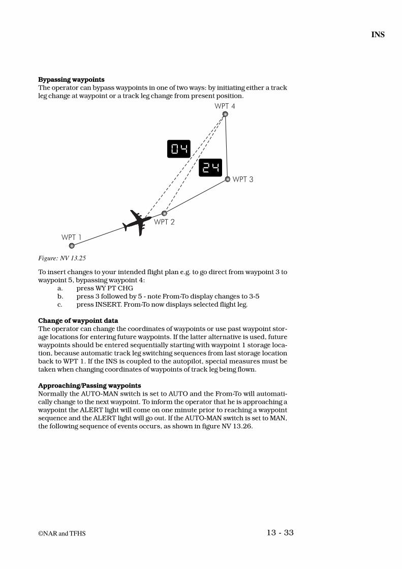
Bypassing waypointsThe operator can bypass waypoints in one of two ways: by initiating either a trackleg change at waypoint or a track leg change from present position.
Figure: NV 13.25
To insert changes to your intended flight plan e.g. to go direct from waypoint 3 towaypoint 5, bypassing waypoint 4:
a. press WY PT CHGb. press 3 followed by 5 - note From-To display changes to 3-5c. press INSERT. From-To now displays selected flight leg.
Change of waypoint dataThe operator can change the coordinates of waypoints or use past waypoint stor-age locations for entering future waypoints. If the latter alternative is used, futurewaypoints should be entered sequentially starting with waypoint 1 storage loca-tion, because automatic track leg switching sequences from last storage locationback to WPT 1. If the INS is coupled to the autopilot, special measures must betaken when changing coordinates of waypoints of track leg being flown.
Approaching/Passing waypointsNormally the AUTO-MAN switch is set to AUTO and the From-To will automati-cally change to the next waypoint. To inform the operator that he is approaching awaypoint the ALERT light will come on one minute prior to reaching a waypointsequence and the ALERT light will go out. If the AUTO-MAN switch is set to MAN,the following sequence of events occurs, as shown in figure NV 13.26.

General Navigation
13 - 34 ©NAR and TFHS
Figure: NV 13.26
1. ALERT lights one minute before leg switch.
2. The aircraft continues flying the original flight path (from 6 to 7 in theexample).
3. The FROM-TO display does not change.
4. The ALERT indicator starts flashing when aircraft passes TO waypoint,and the aircraft continues flying on the original track.
5. It will be necessary to either set AUTO-MAN switch to AUTO or to make anin Flight Course Change, which is the same routine as used for bypassing awaypoint. The moral is to stay in Auto !
System check and updatingDespite the high level of reliability, the INS system (as all other navigation sys-tems) should be regularly monitored for incorrect presentations of information.The internally derived positional data should if possible be checked against othernavigational sources and updated if it is obvious that the INS position is inaccu-rate. Updating should be based on an accurate fix like station passage, visualflying overhead a known position or dual DME fix.
Approximate checks of the INS can be made also by using the basic knowledge ofthe form of the Earth, Rhumb Lines, Great Circles and directions to come up withestimates on the distance, desired track and track made good between waypoints.The accuracy of the INS should always be determined at the end of each flight andprior to system turn off. The check should be made when the aircraft is parked ata known location, by comparing the INS position with the ramp coordinates at thedestination.
To do this the ramp position is inserted as a waypoint and DIS/TIME selected inorder to check the distance and time between the INS position and the rampposition. The difference is the total radial error for the flight (in nm). Dividing thistotal radial error by the number of hours of INS operation (in NAV mode) will givethe Radial Error Rate in nm/hr.
Difference in INS & Ramp position (nm)Radial Error rate (nm/hr) =
Time in the NAV mode (hrs)

13 - 35
INS
©NAR and TFHS
ExampleFollowing a flight from Washington to London, the INS showed a position of51°16.5’N 000°28.0’W when the aircraft was stationary on the ramp in London.The ramp position is given as 51°08.5’N 000°22.0’W. What is the radial error rateof the INS given that the INS was in the Nav mode for 5 hrs and 24 min.
Figure: NV 13.27
The difference in nautical miles between the two positions is divided by the numberof hours in NAV mode, and the amount of drift per hour can be compared with thepromised accuracy.
13.1.12 Outputs from INS/IRS - SystemOutputs from the INS are normally fed to the FMS to facilitate/assist in the lateralnavigation function of that unit. The outputs may also be fed to the AFCS forattitude control.
For pilot interpretation, the guidance signals can be sent to the EFIS HSI/Navdisplay or to a standard electro mechanical HSI.

General Navigation
13 - 36 ©NAR and TFHS
Figure: NV 13.28