Embed Size (px)
Citation preview

Technical Report III
Caitlin
[Type the company name]
Technical Report III
Nemours Children’s Hospital as a part of The Nemours Foundation
Caitlin Behm
Structural Option
Advisor: Dr. Boothby
11.16.11

Nemours Children’s Hospital as a part of The Nemours Foundation Caitlin Behm Structural Option
November 16th, 2011 The Nemours Children’s Hospital as a part of The Nemours Foundation P a g e 2
Table of Contents
EXECUTIVE SUMMARY .................................................................................................................... 3 BUILDING INTRODUCTION .............................................................................................................. 4 STRUCTURAL OVERVIEW ................................................................................................................ 6
Foundation ............................................................................................................................... 6
Floor System ............................................................................................................................ 6
Framing System ....................................................................................................................... 8
Lateral System ......................................................................................................................... 8
Roof System ............................................................................................................................. 9
DESIGN CODES .............................................................................................................................. 10 BUILDING MATERIALS ................................................................................................................... 11 BUILDING LOADS ........................................................................................................................... 12
Dead Load .............................................................................................................................. 12
Live Load ................................................................................................................................ 13
Snow Load .............................................................................................................................. 13
Rain Load ............................................................................................................................... 13
Wind Load .............................................................................................................................. 14
Seismic Load .......................................................................................................................... 16
LATERAL LOAD DISTRIBUTION ...................................................................................................... 17 ETABS MODEL ............................................................................................................................... 19 LOAD CASES .................................................................................................................................. 21 DRIFT & DISPLACEMENT ............................................................................................................... 22 BUILDING TORSION ....................................................................................................................... 24 OVERTURNING MOMENT & FOUNDATION CONSIDERATION ...................................................... 26 MEMBER CHECK ............................................................................................................................ 27 CONCLUSION ................................................................................................................................. 28 APPENDIX A: WIND LOAD CALCULATIONS ................................................................................... 29 APPENDIX B: SEISMIC CALCULATIONS .......................................................................................... 34 APPENDIX C: STIFFNESS TABLES ................................................................................................... 36 APPENDIX D: FOUNDATION MODEL CHECK ................................................................................. 56 APPENDIX E: MEMBER CHECK ...................................................................................................... 57

Nemours Children’s Hospital as a part of The Nemours Foundation Caitlin Behm Structural Option
November 16th, 2011 The Nemours Children’s Hospital as a part of The Nemours Foundation P a g e 3
Executive Summary: The objective of Technical Report III is to analyze how lateral loads are distributed to each of the shear walls in Nemours Children’s Hospital as a part of The Nemours Foundation, NCHTNF. The results of these analyses will be overviewed later in this summary. This report begins with studying the existing conditions and the prevailing codes to understand the design decisions. NCHTNF is a 7-story building located in Orlando, Florida. The entire complex consists of a hospital, clinic, loading dock data center, central energy plant (CEP), and parking facility. The 600,000 square foot hospital consists of two components: a bed tower and outpatient center. The combined components will provide 85 beds, emergency department, diagnostics and ambulatory programs, educational and research centers, and an outpatient clinic. Stanly Beaman & Sears and Perkins + Will are the architects of the project. Harris Civil Engineers, Simpson Gumpertz & Heger, AECOM, and TLC Engineering for Architecture are responsible for the engineering design of NCHTNF. Skanska USA Building is acting as the construction manager and general contractor of the design-bid-build project, which is scheduled to be completed July 2012 after ground was broken July 2009. Gravity loads from ASCE 7-05 are used to determine the wind and seismic loads for NCHTNF. The building’s geometry is regularized, so proper analysis of these loads can be completed as outlined in ASCE 7-05. NCHTNF is analyzed and modeled as two separate structures because of an expansion joint running through the building. The two structures will be called hospital and clinic. After analyzing the data, the conclusion is wind controls the design of NCHTNF. NCHTNF is constructed with 39 shear walls to resist the lateral loading on the building. The lateral loads are transferred from the floor slabs into the shear walls. These loads are then transferred from the shear walls to the foundation. The relative stiffness of each lateral force resisting member is calculated by determining the fraction of the load the member takes from the total applied force. Different load cases are tested to determine the largest load the NCHTNF could experience. Multiple load cases govern separate situations, which is explained later in the report. ETABS is used to analyze these various cases and determine the displacements, story drifts, center of mass, center of rigidity, and story shears. Further analysis of this data is able to provide torsion, overturning moment, and displacement checks on the building. A typical shear wall is checked to verify the ETABS model, and is found to support the ETABS outputs. After reviewing ETABS’ results and this reports’ analysis, it is determined that the NCHTNF meets the ASCE 7-05 code requirements.

Nemours Children’s Hospital as a part of The Nemours Foundation Caitlin Behm Structural Option
November 16th, 2011 The Nemours Children’s Hospital as a part of The Nemours Foundation P a g e 4
Building Introduction:
NCHTNF is a 7-story building located in Orlando, Florida. The entire complex consists of a hospital, clinic, loading dock data center, central energy plant (CEP), and parking facility. The 600,000 square foot hospital consists of two components: a bed tower and outpatient center. The combined components will provide 85 beds, emergency department, diagnostics and ambulatory programs, educational and research centers, and an outpatient clinic. Stanly Beaman & Sears and Perkins + Will are the architects of the project. Harris Civil Engineers, Simpson Gumpertz & Heger, AECOM, and TLC Engineering for Architecture are responsible for the engineering design of NCHTNF. Skanska USA Building is acting as the construction manager and general contractor of the design-bid-build project, which is scheduled to be completed July 2012 after ground was broken July 2009. The design of this $400 million building uses 2007 Florida Building Code with 2009 updates. The Florida Building Code is based on the International Building Code and subsidiary related codes. NCHTNF pays close attention to the standards concerning the high-velocity hurricane zones due to Orlando’s location. The building is classified as I-2 because the clinic can be considered business class, but the hospital is industrial because of overnight patients, thus making the entire project industrial. The site is an undeveloped parcel of land that underwent clearing and mass grading to reach its current topography. The site location does not have any restrictions presiding over the NCHTNF’s design. The primary structure is concrete with curtain walls dominating the majority of the façade. The glass curtain walls vary between metal sunscreen systems, fritt patterns, and insulated spandrels. Other building materials include ribbed metal panel system, terracotta tile wall system, terrazzo wall panels, and composite metal panels to complement the glass systems in the curtain walls. A curved curtain wall, deep canopies, and two green roof gardens provide additional architectural features to the building design.
NCHTNF is designed to withstand the effects of a category 3 hurricane. The National Oceanic and Atmospheric Administration, NOAA, describes a category 3 hurricane as an event where devastating damage will occur, resulting in injury and death. The Nemours Foundation wants NCHTNF to be listed as a place of refuge, more technically known as an Enhanced Hurricane Protection Area, during a category 3 hurricane. This requires the building’s design to at least meet NOAA’s classification of a category 3 hurricane, having sustained winds of 111-130 mph. To qualify as an Enhanced Hurricane Protection Area, the hospital is designed to these standards with a factor of safety.

Nemours Children’s Hospital as a part of The Nemours Foundation Caitlin Behm Structural Option
November 16th, 2011 The Nemours Children’s Hospital as a part of The Nemours Foundation P a g e 5
This results in a very extensive design for the building envelope. The modular curtain wall, constructed by Trainor, is designed with 30,000 feet of dual sealant joints to allow weeping between the two joints. A probe test is specified to be conducted after the sealant has cured to ensure the sealant joint is working properly. The north side of the building features a curved curtain wall supported by slanted structural columns. The deep canopies and fritt pattern glass, acting as sunshading devices, are prevalent throughout the building, and provide adequate shading from the Florida sun. NCHTNF incorporates several different roofing systems to accommodate different functions of the roof. A fluid-applied membrane acts as the roofing system for the roof gardens that are accessible to patients. Thermoplastic membrane roofing and SBS-modified bituminous membrane roofing comprise the other roofs on the building. A mock-up of the NCHTNF has been tested in a hurricane testing lab in Florida. A 2-story 10-bay mock-up was required to pass various tests to ensure the building envelope will be able to sustain the effects of a category 3 hurricane. Laminated glass and extensive use of roof fasteners are only a few of the reasons why the building envelope meets the standards of the hurricane test. The design of NCHTNF follows the USGBC’s LEED prerequisites and credits needed for certification based on LEED for New Construction 2.2. The building has two green roof gardens on the second and fourth floor roofs as mentioned in the paragraph above. The green roofs double as outdoor gardens for patients as well as sustainability features for the building. NCHTNF has numerous sunshades to block the sun from the vast glass façades. Deep canopies provide shade for large spaces on the south façade of the building. Fritt pattern and insulated spandrel glass systems are also implemented in the building’s design. These devices block some of the intense Florida sun to lessen the load on the HVAC system of the building.

Nemours Children’s Hospital as a part of The Nemours Foundation Caitlin Behm Structural Option
November 16th, 2011 The Nemours Children’s Hospital as a part of The Nemours Foundation P a g e 6
Structural Overview:
NCHTNF bears on spread footings on either improved or natural soils. The hospital and clinic portion of the building are predominately concrete structures with the exception of steel framed mechanical penthouses. The loading dock data center and central energy plant are primarily steel framed structures. The lateral system is comprised of shear walls, which most continue through the entire building height. NCHTNF utilizes unique framing techniques for the wave and sloped curtain wall backup.
Foundation: PSI, the geotechnical firm, performed nineteen borings across the site in January 2009. The soils generally consist of varying types of fine sands graded relatively clean to slightly silty in composition. The boring blow counts record the upper layers of sand to be of medium dense condition, while the lower layers of sand are generally loose to medium dense condition. PSI recommends utilizing shallow foundations only if the foundation design implements soil improvement to increase the allowable bearing capacity of the design. PSI proposes another foundation solution, if soil improvement is not desirable implement a pile foundation system. These reinforced augercast piles will withstand a considerably higher foundation loads than the shallow foundation system. The downside of augercast piles are they can bulge or neck where very loose soils are encountered, requiring stringent monitoring and quality control. Due to the specialized nature of the augercast piles for this project, spread footings with soil improvement is chosen as the foundation system for the NCHTNF. The fact that the water table is measured only 4 feet below the surface raises concerns about excavations. The sump system dewaters shallow excavations while deeper excavations require well-pointing or horizontal sock drains for proper dewatering.
Floor System: NCHTNF has numerous types of floor construction due to different design requirements in different sections of the building. The building contains 5”-6” normal weight concrete as the slab on grade. A few sections of the foundation system utilize mat foundations, varying from 2’ to 4’-3” normal weight concrete. The hospital and clinic are built on normal weight elevated two-way flat slabs, with and without drop panels, varying in depth from 9”-14”. A typical structural floor plan detailing a typical 30’x30’ bay is shown in Figures 1 and 2. The loading dock data center and central energy plant are constructed with a 4-1/2” 1-way slab on 3”-20 GA. composite metal deck, which is supported by a steel frame system. Some specialty areas, such as the green roof and the slab over the lecture hall, vary slightly from the typical slab in the remainder of the building.

Nemours Children’s Hospital as a part of The Nemours Foundation Caitlin Behm Structural Option
November 16th, 2011 The Nemours Children’s Hospital as a part of The Nemours Foundation P a g e 7
There are 29 different superstructure concrete beams in the NCHTNF. The beams range from 16” x20” to 89” x 48”. The hospital and clinic predominately consist of 15’ x 30’ bays with a few 15’ x 15’ and 30’ x 30’ bays to accommodate for the elevator and stair core. The bays in the loading dock data center are far irregular. They vary from the smallest being 21’ x 30’-3” to the largest being 30’ x 45’ – 2”. The central energy plant also has a variety of bay sizes, ranging from 22’ x 11’-2” to 22’ x 26’-7”.
Figures 1 & 2 – Level 1 Typical Structural Bay (30’x30’) with Key Plan. Courtesy SGH.

Nemours Children’s Hospital as a part of The Nemours Foundation Caitlin Behm Structural Option
November 16th, 2011 The Nemours Children’s Hospital as a part of The Nemours Foundation P a g e 8
Framing System: The columns supporting the NCHTNF are mostly concrete columns, with steel columns supporting the mechanical penthouses on the 7th floor. The concrete columns supporting the hospital and clinic typically start at a dimension of 30” x 30” and taper to 22” x 22” at Level 6. The mechanical penthouse is constructed with W12x53 columns on both the hospital and clinic. W14x109, W10x49, W10x60, and W14x68 mainly support the loading dock data center. HSS8x8x and HSS12x8 dominate the central energy plant’s supporting structure along with a few W12x65 and W12x79 columns.
Lateral System: Shear walls resist lateral loads in the hospital and clinic of the NCHTNF. These walls are 12-14” thick and tie into mat foundations with dowels matching the typical wall reinforcement, mostly #8 bars. The shear walls are located in the elevator/stair core in the hospital and in the elevator bays and lecture hall in the clinic, which are highlighted below in green in Figure 3. Also, the central energy plant has one shear wall, the rest of the lateral system of the CEP being braced framing which is discussed in the next paragraph. A few shear walls include knockout panels to plan for future openings.
Figure 3 – Level 1 Structural Floor Plan Highlighting the Lateral System. Courtesy SGH.
Key:
- Reinforced
Concrete Shear
Walls
- Steel
Concentrically
Braced Frames

Nemours Children’s Hospital as a part of The Nemours Foundation Caitlin Behm Structural Option
November 16th, 2011 The Nemours Children’s Hospital as a part of The Nemours Foundation P a g e 9
Steel concentrically braced frames resist lateral loads in the loading dock data center and central energy plant, highlighted above in orange in Figure 3. Diagonal members, HSS6x6 and HSS5x5, brace into W14, W16, and W21 beams in the loading dock data center. Diagonal members, HSS8x8 and HSS8x8, brace into W18 and W21 beams respectively in the central energy plant. As mentioned above, the central energy plant has one shear wall along with the steel concentrically braced frame system. The load path in NCHTNF starts with the wind load against the façade of the building. Once the load is applied to the façade it is transferred to the diaphragms on each floor. The diaphragms then transfer the load to the lateral elements, being reinforced concrete shear walls in the hospital and clinic and steel concentrically braced frames in the loading dock data center and CEP. These lateral elements transfer the load to the foundation system, the final step of the load path of NCHTNF.
Roof System: NCHTNF has several different roofing systems to accommodate different functions of the roof. A fluid-applied membrane acts as the roofing system for the roof garden that is accessible to patients and also doubles as a green roof. The fluid-applied membrane utilizes type IV extruded polystyrene board insulation. The other roofs on the building are constructed with thermoplastic membrane roofing and SBS-modified bituminous membrane roofing. Each of these roofs use polyisocyanurate board insulation, which is type II glass fiber mat facer. The other roofing system is 1-1/2” – 18 GA. metal roof deck, located on the loading deck data center, central energy plant, and mechanical penthouses on the 7th floor.
Nemours Children’s Hospital as a part of The Nemours Foundation Caitlin Behm Structural Option
November 16th, 2011 The Nemours Children’s Hospital as a part of The Nemours Foundation P a g e 1 0
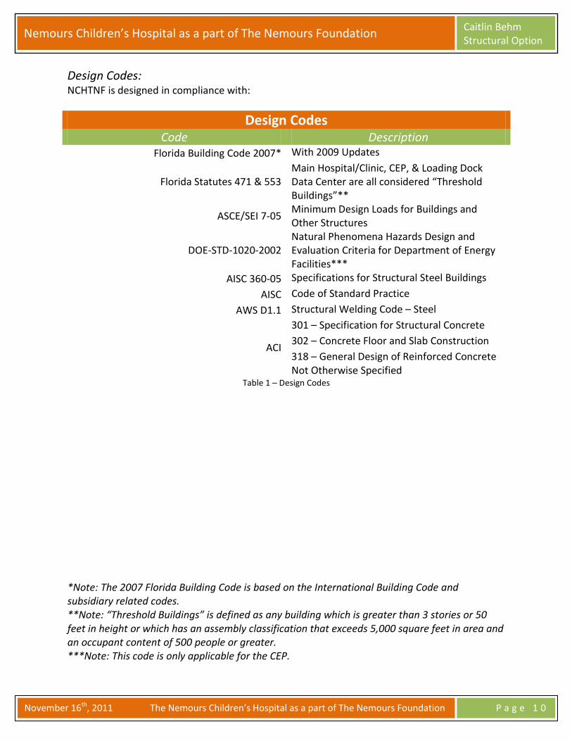
Design Codes: NCHTNF is designed in compliance with:
Design Codes Code Description
Florida Building Code 2007* With 2009 Updates
Florida Statutes 471 & 553 Main Hospital/Clinic, CEP, & Loading Dock Data Center are all considered “Threshold Buildings”**
ASCE/SEI 7-05 Minimum Design Loads for Buildings and Other Structures
DOE-STD-1020-2002 Natural Phenomena Hazards Design and Evaluation Criteria for Department of Energy Facilities***
AISC 360-05 Specifications for Structural Steel Buildings
AISC Code of Standard Practice
AWS D1.1 Structural Welding Code – Steel
ACI
301 – Specification for Structural Concrete
302 – Concrete Floor and Slab Construction
318 – General Design of Reinforced Concrete Not Otherwise Specified
Table 1 – Design Codes
*Note: The 2007 Florida Building Code is based on the International Building Code and subsidiary related codes. **Note: “Threshold Buildings” is defined as any building which is greater than 3 stories or 50 feet in height or which has an assembly classification that exceeds 5,000 square feet in area and an occupant content of 500 people or greater. ***Note: This code is only applicable for the CEP.
Nemours Children’s Hospital as a part of The Nemours Foundation Caitlin Behm Structural Option
November 16th, 2011 The Nemours Children’s Hospital as a part of The Nemours Foundation P a g e 1 1
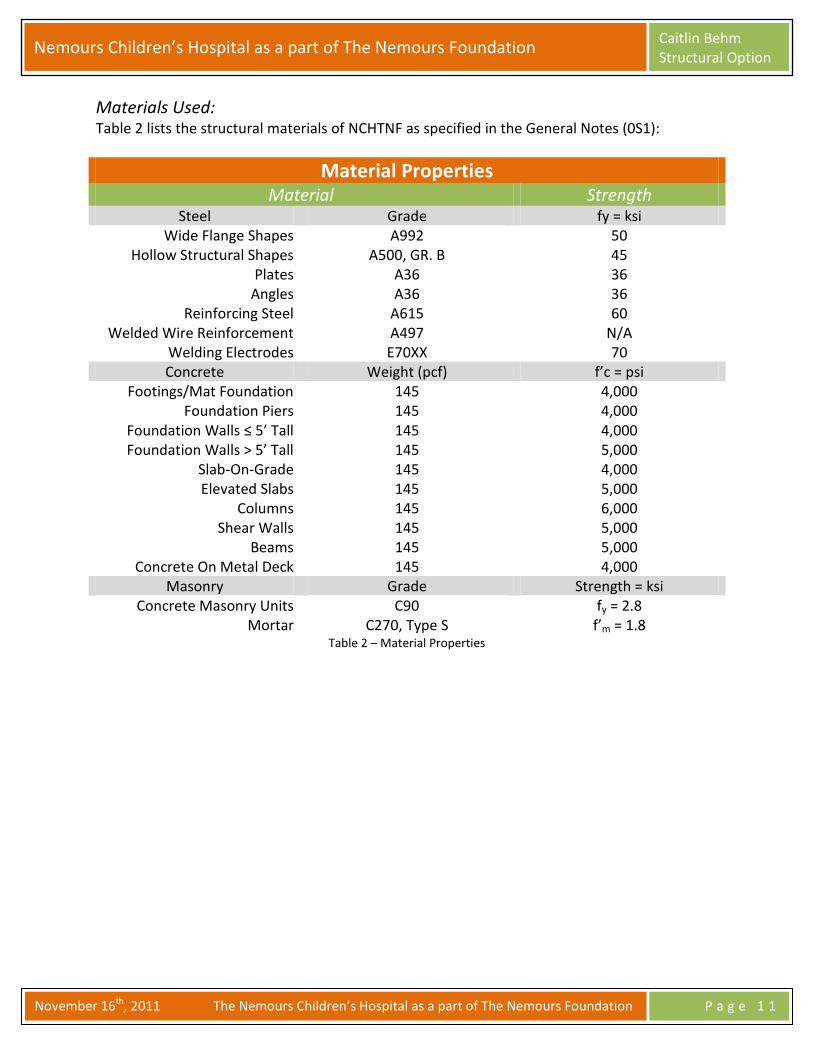
Materials Used: Table 2 lists the structural materials of NCHTNF as specified in the General Notes (0S1):
Material Properties Material Strength
Steel Grade fy = ksi Wide Flange Shapes A992 50
Hollow Structural Shapes A500, GR. B 45 Plates A36 36
Angles A36 36 Reinforcing Steel A615 60
Welded Wire Reinforcement A497 N/A Welding Electrodes E70XX 70 Concrete Weight (pcf) f’c = psi
Footings/Mat Foundation 145 4,000 Foundation Piers 145 4,000
Foundation Walls ≤ 5’ Tall 145 4,000 Foundation Walls > 5’ Tall 145 5,000
Slab-On-Grade 145 4,000 Elevated Slabs 145 5,000
Columns 145 6,000 Shear Walls 145 5,000
Beams 145 5,000 Concrete On Metal Deck 145 4,000
Masonry Grade Strength = ksi Concrete Masonry Units C90 fy = 2.8
Mortar C270, Type S f’m = 1.8 Table 2 – Material Properties

Nemours Children’s Hospital as a part of The Nemours Foundation Caitlin Behm Structural Option
November 16th, 2011 The Nemours Children’s Hospital as a part of The Nemours Foundation P a g e 1 2
Building Loads: Dead Loads: The general notes in the front end of the structural list the superimposed dead loads. The dead loads are determined using the weights of the components or systems, which the IBC 2009 section 1606.2 states as the proper way to determine dead loads.
Superimposed Dead Loads Plan Areas Loads (psf)
Typical Floors 12 Mechanical Floors 62 Light Green Roofs 54
Medium Green Roofs 209 Heavy Green Roofs 389
Typical Roof 24
Special Roofs
Plaza Roof (at grade) 50 Café Portal Roof 45
Entry Portal 45 Ed Low Roof 45
Clinic Roof Wing 189 Stitch Roof 20
Table 3 – Superimposed Dead Loads
Nemours Children’s Hospital as a part of The Nemours Foundation Caitlin Behm Structural Option
November 16th, 2011 The Nemours Children’s Hospital as a part of The Nemours Foundation P a g e 1 3
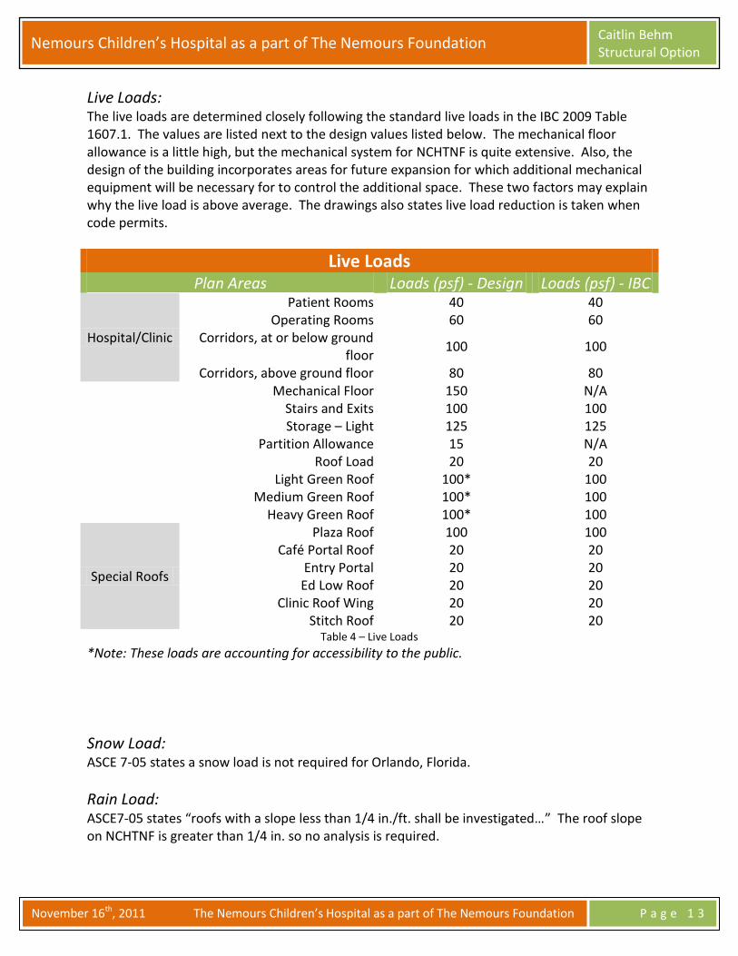
Live Loads: The live loads are determined closely following the standard live loads in the IBC 2009 Table 1607.1. The values are listed next to the design values listed below. The mechanical floor allowance is a little high, but the mechanical system for NCHTNF is quite extensive. Also, the design of the building incorporates areas for future expansion for which additional mechanical equipment will be necessary for to control the additional space. These two factors may explain why the live load is above average. The drawings also states live load reduction is taken when code permits.
Live Loads Plan Areas Loads (psf) - Design Loads (psf) - IBC
Hospital/Clinic
Patient Rooms 40 40 Operating Rooms 60 60
Corridors, at or below ground floor
100 100
Corridors, above ground floor 80 80 Mechanical Floor 150 N/A
Stairs and Exits 100 100 Storage – Light 125 125
Partition Allowance 15 N/A Roof Load 20 20
Light Green Roof 100* 100 Medium Green Roof 100* 100
Heavy Green Roof 100* 100
Special Roofs
Plaza Roof 100 100 Café Portal Roof 20 20
Entry Portal 20 20 Ed Low Roof 20 20
Clinic Roof Wing 20 20 Stitch Roof 20 20
Table 4 – Live Loads
*Note: These loads are accounting for accessibility to the public.
Snow Load: ASCE 7-05 states a snow load is not required for Orlando, Florida.
Rain Load: ASCE7-05 states “roofs with a slope less than 1/4 in./ft. shall be investigated…” The roof slope on NCHTNF is greater than 1/4 in. so no analysis is required.

Nemours Children’s Hospital as a part of The Nemours Foundation Caitlin Behm Structural Option
November 16th, 2011 The Nemours Children’s Hospital as a part of The Nemours Foundation P a g e 1 4
Wind Load: The wind analysis follows chapter 6 in ASCE 7-05 to determine the wind load on NCHTNF. All hand calculations and expanded excel spreadsheets are found in Appendix A. The Design Criteria, as stated in Appendix A, match the criteria on the general notes of the structural drawings. An explanation of design assumptions are as follows: The building is assumed flexible because the fundamental frequency is below the 1 Hz requirement. Thus, the gust factor is not 0.85, but instead calculated using the equation for the gust factor of a flexible building, outlined in Appendix A. When calculating the gust factor, the damping ratio of the building is assumed to be 1.0. Also, the basic wind speed is not 110 mph as stated in ASCE 7-05, instead V=157mph. The owner wants the building to withstand a category three hurricane, so it is classified as a center of refuge in the event that a category 3 hurricane approaches Orlando, Florida. The building is assumed enclosed because NCHTNF has non-operable windows. The building geometry is simplified so the height of the building is assumed at 135 ft, the height of the mechanical penthouse. The mechanical penthouse encompasses most of the surface area of the building, confirming my assumption that the building height can be averaged to 135 ft. The building is modeled as two separate structures, the hospital and clinic, divided along the expansion joint shown in Figure 4 below. Two separate wind analyses are calculated for each structure in Appendix A. The calculated values differ from Simpson, Gumpertz & Heger’s calculations because their calculations are based on method 3, wind tunnel analysis.
Figure 4 – Generalized Geometry for Wind Analysis. Courtesy SGH.
Expansion Joint
Clinic Hospital

Nemours Children’s Hospital as a part of The Nemours Foundation Caitlin Behm Structural Option
November 16th, 2011 The Nemours Children’s Hospital as a part of The Nemours Foundation P a g e 1 5
The resulting building shear and overturning moment are calculated in the excel spreadsheet, as listed in Appendix A. The applied wind pressures are shown in the North-South and East-West directions in Figures 5 & 6 below.
Figure 5 – Wind Pressures Vertical Distribution, North-South Direction
Figure 6 – Wind Pressures Vertical Distribution, East-West Direction
39.97 psf 38.19 psf 37.31 psf 36.12 psf 34.34 psf 32.57 psf 30.35 psf 25.17 psf 25.17 psf
19.36 psf
40.90 psf 39.08 psf 38.18 psf 36.96 psf 35.15 psf 33.33 psf 31.06 psf 25.75 psf 25.75 psf
19.94 psf
Roof
Roof Penthouse
5
1
Roof
Roof Penthouse
5
1
4
3
4
3
6
Ground
6
Ground
2
2
Nemours Children’s Hospital as a part of The Nemours Foundation Caitlin Behm Structural Option
November 16th, 2011 The Nemours Children’s Hospital as a part of The Nemours Foundation P a g e 1 6
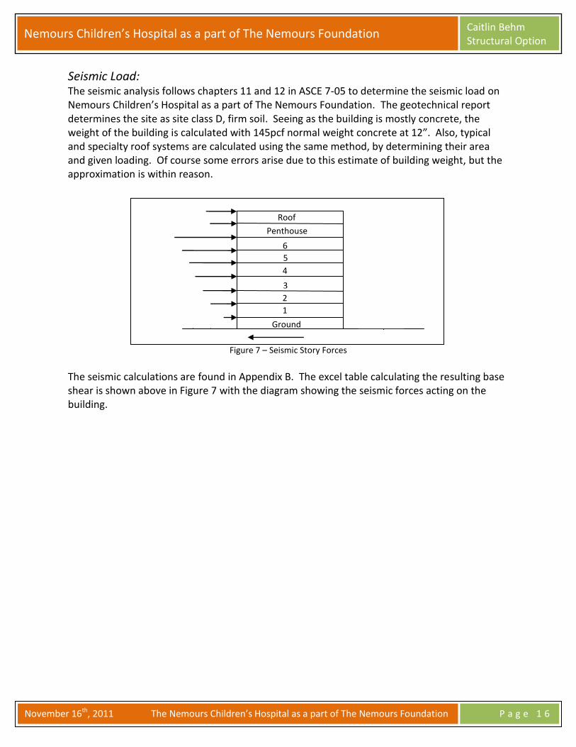
Seismic Load: The seismic analysis follows chapters 11 and 12 in ASCE 7-05 to determine the seismic load on Nemours Children’s Hospital as a part of The Nemours Foundation. The geotechnical report determines the site as site class D, firm soil. Seeing as the building is mostly concrete, the weight of the building is calculated with 145pcf normal weight concrete at 12”. Also, typical and specialty roof systems are calculated using the same method, by determining their area and given loading. Of course some errors arise due to this estimate of building weight, but the approximation is within reason.
Figure 7 – Seismic Story Forces
The seismic calculations are found in Appendix B. The excel table calculating the resulting base shear is shown above in Figure 7 with the diagram showing the seismic forces acting on the building.
Roof
Roof Penthouse
5
1
4
3
6
Ground
2

Nemours Children’s Hospital as a part of The Nemours Foundation Caitlin Behm Structural Option
November 16th, 2011 The Nemours Children’s Hospital as a part of The Nemours Foundation P a g e 1 7
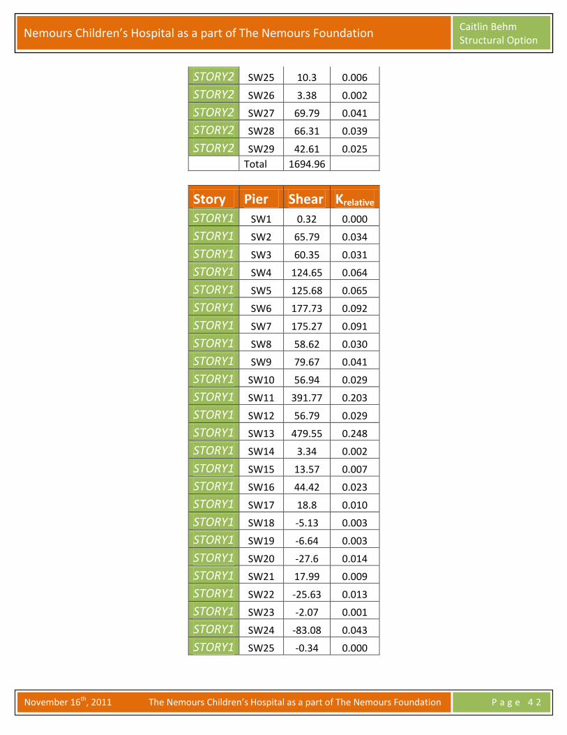
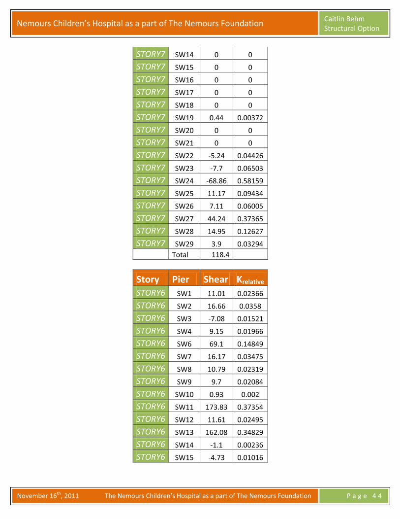
Lateral Load Distribution: Lateral loads are resisted by 39 shear walls in NCHTNF. The shear walls are shown in Figures 8 & 9, highlighted in orange. The floor plan below also provides a key for the ETABS calculations that label each shear wall numerically. The ETABS model for this report analyzes the building using a rigid diaphragm. The diaphragm transfers the lateral loads to the shear walls, where these walls transfer the lateral load to the foundations. The relative stiffness of each shear wall is subsequently calculated, relating the amount of force seen at that member compared to the total force applied to the floor level, as shown in Appendix C. Due to shear wall height irregularity, the relative stiffness is calculated at each level, so the controlling relative stiffness can be more accurately determined.
Figure 8 – Hospital Shear Wall Plan
KEY: SW1 = A SW2 = B SW3 = C SW4 = D SW 5 = E SW 6 = F SW 7 = G SW 8 = H SW 9 = I SW 10 = J SW 11 = K SW 12 = L SW 13 = M SW 14 = N SW 15 = O SW 16 = P SW 17 = Q SW 18 = R SW 19 = S SW 20 = T SW 21 = U SW 22 = V SW 23 = W SW 24 = X SW 25 = Y SW 26 = Z SW 27 = AA SW 28 = AB SW 29 = AC
JJ
KK NN
YY
ZZ
AA BB CC
DD
EE
FF GG
HH
II
LL
MM
OO
PP QQ
RR SS TT
UU
VV
WW XX
AAAA
AABB
AACC

Nemours Children’s Hospital as a part of The Nemours Foundation Caitlin Behm Structural Option
November 16th, 2011 The Nemours Children’s Hospital as a part of The Nemours Foundation P a g e 1 8
Figure 9 – Clinic Shear Wall Plan
An Excel spreadsheet is used to calculate the distribution of the lateral loads to the 29 shear walls in the hospital and 10 shear walls in the clinic. The calculations considered both the controlling seismic and wind cases for the hospital and clinic. Stiffness is calculated at each floor because some shear walls differ from the typical shear wall height and some shear walls change width in their elevation. See Appendix C to view all of the stiffness tables.
KEY: SW1 = A SW2 = B SW3 = C SW4 = D SW5 = E SW6 = F SW7 = G SW8 = H SW9 = I SW10 = J
AA
BB CC
DD
EE FF
GG
HH
II
JJ

Nemours Children’s Hospital as a part of The Nemours Foundation Caitlin Behm Structural Option
November 16th, 2011 The Nemours Children’s Hospital as a part of The Nemours Foundation P a g e 1 9
ETABS Model: As mentioned before, NCHTNF is analyzed with two different models to represent a building expansion joint. The hospital is represented in Figures 10 & 11, while the clinic is shown in Figures 12 & 13. Shear walls are the only elements modeled in ETABS because these walls are the only members in the building to resist lateral loads. The shear walls are meshed to a maximum of 24” instead of 24”x24” to simplify the calculations. The irregularity of the elevation of some of the shear walls cause errors in the ETABS when 24”x24” is specified. The moment of inertia is decreased 50% to account for the cracked section property. Each floor is modeled as a rigid diaphragm with an additional self weight added to represent the weight of the floor system.
Figure 10 – First Floor Hospital ETABS Model
Figure 11 – 3D Hospital ETABS Model

Nemours Children’s Hospital as a part of The Nemours Foundation Caitlin Behm Structural Option
November 16th, 2011 The Nemours Children’s Hospital as a part of The Nemours Foundation P a g e 2 0
Figure 12 – First Floor Clinic ETABS Model
Figure 13 – 3D Clinic ETABS Model

Nemours Children’s Hospital as a part of The Nemours Foundation Caitlin Behm Structural Option
November 16th, 2011 The Nemours Children’s Hospital as a part of The Nemours Foundation P a g e 2 1
Load Cases:
ASCE 7-05 strength design load combinations are used for the building assessment. The load cases consider both gravity and lateral loads within the NCHTNF. The load combinations utilized in this technical report are listed below.
1.4D 1.2D+1.6L+0.5Lr 1.2D+1.6Lr+0.5W 1.2D+1.0W+1.0L+0.5Lr 1.2D+1.0E+1.0L 0.9D+1.0W 0.9D+1.0E
The load cases are input into the ETABS model where the displacements and drifts determine which case, or cases, govern. NCHTNF has different load cases governing depending on the various shear walls, so all load cases are considered.

Nemours Children’s Hospital as a part of The Nemours Foundation Caitlin Behm Structural Option
November 16th, 2011 The Nemours Children’s Hospital as a part of The Nemours Foundation P a g e 2 2
Drift & Displacement: Story drift and lateral displacement are checked in the ETABS model. Referencing ASCE 7-10, the allowable seismic story drift is 0.010hx for category IV. The allowable displacement for wind is L/400. Unfactored loads are used to determine the displacements and story drifts, as shown below in Figures 14 – 17. The actual drifts and displacements are within the limits after comparing the ETABS results with the code.
Figure 14 – Hospital Wind Drift & Displacement
Figure 15 – Hospital Seismic Drift & Displacement
Figure 16 – Clinic Wind Drift & Displacement
Story X Displacement (in) Y Displacement (in) X Story Drift (in) Y Story Drift (in) Allowable Drift (in)
STORY8 0.1476 0.0354 0.22194 0.1053 4.05
STORY7 0.1145 0.0264 0.243 0.1053 4.05
STORY6 0.1017 0.0027 0.21528 0.09243 4.05
STORY5 0.082 0.0019 0.18018 0.07623 4.05
STORY4 0.0651 0.0051 0.13851 0.05751 4.05
STORY3 0.0461 0.0032 0.09576 0.03843 4.05
STORY2 0.0287 0.0005 0.0513 0.01845 4.05
STORY1 0.0079 0.0002 0.01044 0.00288 4.05
Hospital Wind Drift and Displacement
Story X Displacement (in) Y Displacement (in) X Story Drift (in) Y Story Drift (in) Allowable Drift (in)
STORY8 0.1022 0.0373 0.15228 0.1539 2.7
STORY7 0.0837 0.0296 0.2376 0.13095 1.8
STORY6 0.0801 -0.0011 0.2106 0.11583 1.8
STORY5 0.0655 -0.0011 0.1782 0.09504 1.8
STORY4 0.0542 0.0043 0.14013 0.0729 1.8
STORY3 0.0388 0.0027 0.09891 0.04914 1.8
STORY2 0.0241 -0.0003 0.05265 0.02475 2.7
STORY1 0.0062 0.0001 0.01008 0.00396 1.8
Hospital Seismic Drift and Displacement
Story X Displacement (in) Y Displacement (in) X Story Drift (in) Y Story Drift (in) Allowable Drift (in)
STORY8 0.9121 0.144 3.18006 1.14048 4.05
STORY7 0.6269 0.0856 1.512 0.5508 4.05
STORY6 0.5859 0.0714 1.58769 0.37206 4.05
STORY5 0.4602 0.0548 1.28997 0.30195 4.05
STORY4 0.3396 0.039 0.97119 0.22599 4.05
STORY3 0.2285 0.0247 1.148805 0.15183 4.05
STORY2 0.1032 0.0124 0.35685 0.06615 4.05
STORY1 0.0246 0.0032 0.04968 0.01134 4.05
Clinic Wind Drift and Displacement

Nemours Children’s Hospital as a part of The Nemours Foundation Caitlin Behm Structural Option
November 16th, 2011 The Nemours Children’s Hospital as a part of The Nemours Foundation P a g e 2 3
Figure 17 – Clinic Seismic Drift & Displacement
Story X Displacement (in) Y Displacement (in) X Story Drift (in) Y Story Drift (in) Allowable Drift (in)
STORY8 0.2665 0.0398 0.73872 0.25596 2.7
STORY7 0.1995 0.0274 0.49275 0.01336635 1.8
STORY6 0.1913 0.0234 0.51246 0.12168 1.8
STORY5 0.1509 0.018 0.42174 0.099 1.8
STORY4 0.1116 0.0128 0.31995 0.07452 1.8
STORY3 0.075 0.0081 0.21735 0.04977 1.8
STORY2 0.0336 0.004 0.11655 0.0216 2.7
STORY1 0.0078 0.001 0.01566 0.0036 1.8
Clinic Seismic Drift and Displacement
Nemours Children’s Hospital as a part of The Nemours Foundation Caitlin Behm Structural Option
November 16th, 2011 The Nemours Children’s Hospital as a part of The Nemours Foundation P a g e 2 4
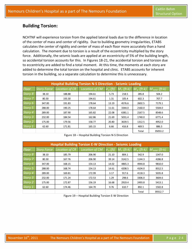
Building Torsion: NCHTNF will experience torsion from the applied lateral loads due to the difference in location of the center of mass and center of rigidity. Due to building geometry irregularities, ETABS calculates the center of rigidity and center of mass of each floor more accurately than a hand calculation. The moment due to torsion is a result of the eccentricity multiplied by the story force. Additionally, the seismic loads are applied at an eccentricity of 5% of the building length, so accidental torsion accounts for this. In Figures 18-21, the accidental torsion and torsion due to eccentricity are added to find a total moment. At this time, the moments at each story are added to determine the total torsion on the hospital and clinic. ETABS accounts for inherent torsion in the building, so a separate calculation to determine this is unnecessary.
Figure 18 – Hospital Building Torsion N-S Direction
Figure 19 – Hospital Building Torsion E-W Direction
Floor Story Force Location of CR Location of CM e y (ft) M t (ft-k) M a (ft-k) M total (ft-k)
Story 8 38.10 188.88 194.61 5.73 218.5 285.8 504.2
Story 7 80.30 193.30 194.61 1.31 105.4 602.3 707.7
Story 6 347.00 191.83 178.64 13.19 4576.6 2602.5 7179.1
Story 5 288.00 190.25 178.64 11.61 3344.0 2160.0 5504.0
Story 4 289.00 187.90 165.82 22.08 6381.1 2167.5 8548.6
Story 3 232.00 184.54 162.86 21.69 5031.4 1740.0 6771.4
Story 2 175.00 179.56 158.77 20.80 3639.5 1312.5 4952.0
Story 1 62.60 171.81 165.15 6.66 416.8 469.5 886.3
Total 35053.2
Hospital Building Torsion N-S Direction - Seismic Loading
Floor Story Force Location of CR Location of CM e x (ft) M t (ft-k) M a (ft-k) M total (ft-k)
Story 8 38.10 185.79 206.90 21.10 804.1 542.9 1347.0
Story 7 80.30 167.76 206.90 39.14 3142.5 1144.3 4286.8
Story 6 347.00 168.15 154.13 14.02 4865.3 4944.8 9810.0
Story 5 288.00 168.74 154.13 14.61 4208.5 4104.0 8312.5
Story 4 289.00 169.81 172.99 3.17 917.6 4118.3 5035.8
Story 3 232.00 171.24 172.53 1.29 298.6 3306.0 3604.6
Story 2 175.00 172.87 156.19 16.68 2919.4 2493.8 5413.1
Story 1 62.60 174.46 164.70 9.76 610.7 892.1 1502.8
Total 39312.7
Hospital Building Torsion E-W Direction - Seismic Loading

Nemours Children’s Hospital as a part of The Nemours Foundation Caitlin Behm Structural Option
November 16th, 2011 The Nemours Children’s Hospital as a part of The Nemours Foundation P a g e 2 5
Figure 20 – Clinic Building Torsion N-S Direction
Figure 21 – Clinic Building Torsion E-W Direction
Floor Story Force Location of CR Location of CM e y (ft) M t (ft-k) M a (ft-k) M total (ft-k)
Story 8 23.30 492.79 419.50 73.29 1707.6 104.9 1812.5
Story 7 49.00 490.56 419.50 71.06 3482.1 220.5 3702.6
Story 6 121.00 489.63 400.40 89.23 10797.3 544.5 11341.8
Story 5 99.80 489.61 400.40 89.21 8903.5 449.1 9352.6
Story 4 79.70 489.57 400.40 89.17 7106.8 358.7 7465.5
Story 3 60.10 489.95 400.40 89.55 5381.8 270.5 5652.3
Story 2 40.90 501.85 432.51 69.34 2836.0 184.1 3020.1
Story 1 22.90 489.41 436.37 53.04 1214.6 103.1 1317.6
Total 43664.9
Clinic Building Torsion N-S Direction - Seismic Loading
Floor Story Force Location of CR Location of CM e x (ft) M t (ft-k) M a (ft-k) M total (ft-k)
Story 8 23.30 136.95 159.00 22.05 513.7 284.3 797.9
Story 7 49.00 136.59 159.00 22.41 1098.0 597.8 1695.8
Story 6 121.00 136.59 160.21 23.62 2857.7 1476.2 4333.9
Story 5 99.80 137.19 160.21 23.02 2297.8 1217.6 3515.4
Story 4 79.70 138.11 160.21 22.10 1761.5 972.3 2733.9
Story 3 60.10 139.63 160.21 20.58 1237.0 733.2 1970.2
Story 2 40.90 142.46 159.90 17.45 713.5 499.0 1212.5
Story 1 22.90 145.11 162.29 17.18 393.3 279.4 672.7
Total 16932.3
Clinic Building Torsion E-W Direction - Seismic Loading
Nemours Children’s Hospital as a part of The Nemours Foundation Caitlin Behm Structural Option
November 16th, 2011 The Nemours Children’s Hospital as a part of The Nemours Foundation P a g e 2 6
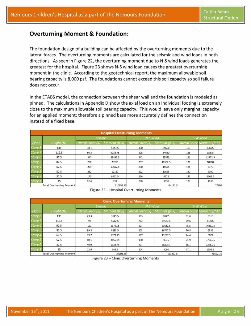
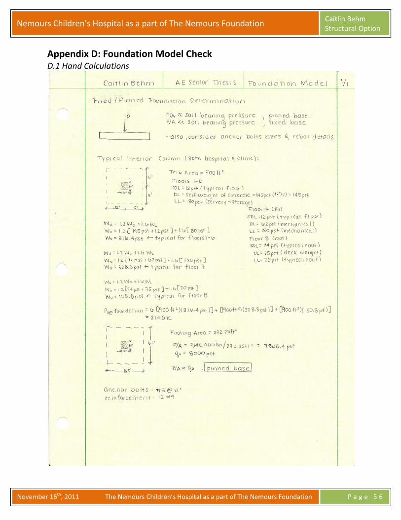
Overturning Moment & Foundation: The foundation design of a building can be affected by the overturning moments due to the lateral forces. The overturning moments are calculated for the seismic and wind loads in both directions. As seen in Figure 22, the overturning moment due to N-S wind loads generates the greatest for the hospital. Figure 23 shows N-S wind load causes the greatest overturning moment in the clinic. According to the geotechnical report, the maximum allowable soil bearing capacity is 8,000 psf. The foundations cannot exceed this soil capacity so soil failure does not occur. In the ETABS model, the connection between the shear wall and the foundation is modeled as pinned. The calculations in Appendix D show the axial load on an individual footing is extremely close to the maximum allowable soil bearing capacity. This would leave only marginal capacity for an applied moment; therefore a pinned base more accurately defines the connection instead of a fixed base.
Figure 22 – Hospital Overturning Moments
Figure 23 – Clinic Overturning Moments
Lateral Force (k) Moment (ft-k) Lateral Force (k) Moment (ft-k) Lateral Force (k)Moment (ft-k)
Story 8 135 38.1 5143.5 190 25650 103 13905
Story 7 112.5 80.3 9033.75 308 34650 166 18675
Story 6 97.5 347 33832.5 242 23595 131 12772.5
Story 5 82.5 288 23760 237 19552.5 128 10560
Story 4 67.5 289 19507.5 230 15525 124 8370
Story 3 52.5 232 12180 222 11655 120 6300
Story 2 37.5 175 6562.5 266 9975 143 5362.5
Story 1 15 62.6 939 238 3570 129 1935
110958.75 144172.5 77880Total Overturning Moment
Seismic N-S Wind E-W Wind
Floor Height (ft)
Hospital Overturning Moments
Lateral Force (k) Moment (ft-k) Lateral Force (k) Moment (ft-k) Lateral Force (k)Moment (ft-k)
Story 8 135 23.3 3145.5 163 22005 61.6 8316
Story 7 112.5 49 5512.5 263 29587.5 99.6 11205
Story 6 97.5 121 11797.5 207 20182.5 78.5 7653.75
Story 5 82.5 99.8 8233.5 203 16747.5 76.8 6336
Story 4 67.5 79.7 5379.75 197 13297.5 74.4 5022
Story 3 52.5 60.1 3155.25 190 9975 71.9 3774.75
Story 2 37.5 40.9 1533.75 227 8512.5 86.1 3228.75
Story 1 15 22.9 343.5 204 3060 77.1 1156.5
39101.25 123367.5 46692.75Total Overturning Moment
Clinic Overturning Moments
Floor Height (ft)
Seismic N-S Wind E-W Wind

Nemours Children’s Hospital as a part of The Nemours Foundation Caitlin Behm Structural Option
November 16th, 2011 The Nemours Children’s Hospital as a part of The Nemours Foundation P a g e 2 7
Member Check: A spot check is carried out on one of the shear walls in the hospital. The spot check is to ensure the wall can withstand the applied gravity and lateral loads that are tested in ETABS. The loads used to verify the member’s adequacy are obtained from the ETABS output. The shear wall is found to be adequate for the applied loads in NCHTNF seeing as its displacement passed ASCE 7-05 code standards. A detailed calculation can be found in Appendix E.
Figure 24 – NCHTNF Hospital Partial Plan
Figure 25 – Hospital Shear Wall #19

Nemours Children’s Hospital as a part of The Nemours Foundation Caitlin Behm Structural Option
November 16th, 2011 The Nemours Children’s Hospital as a part of The Nemours Foundation P a g e 2 8
Conclusion: This report analyzes the lateral system in NCHTNF. The use of the ETABS model allows thorough studies of the 39 shears walls in the building because ETABS provides a more detailed and accurate analysis than hand calculations because of irregular building geometry. ETABS’ detailed data on each of the shear walls is how the program provides its accurate analysis. Building torsion and overturning moments are also calculated, using ETABS outputs, to study the effect on the foundation from the lateral system. The ETABS model is also used to calculate story drifts, story displacements, stiffness, and spot checks. After studying the ETABS analysis, NCHTNF meets the ASCE 7-05 standards for drift and displacement. The spot check of the shear wall #19 proves the typical shear wall meet code standards for strength and deflection. In conclusion, NCHTNF’s lateral system is adequate for resisting the lateral loads the building will experience.

Nemours Children’s Hospital as a part of The Nemours Foundation Caitlin Behm Structural Option
November 16th, 2011 The Nemours Children’s Hospital as a part of The Nemours Foundation P a g e 2 9
Appendix A: Wind Load Calculations
A.1 Wind Pressures Table A.1-1 Hospital North-South Wind Calculations
Table A.1-2 Hospital East-West Wind Calculations
Floor Elevation z k z q z q h Windward(psf) Leeward (psf) Trib. Area (ft 2 ) Force (k)
Ground 89.1 0 0.85 52.43 83.27 25.17 -19.36 2137.5 95
1 104.1 15 0.85 52.43 83.27 25.17 -19.36 5343.75 238
2 126.6 37.5 1.025 63.22 83.27 30.35 -19.36 5343.75 266
3 141.6 52.5 1.1 67.85 83.27 32.57 -19.36 4275 222
4 156.6 67.5 1.16 71.55 83.27 34.34 -19.36 4275 230
5 171.6 82.5 1.22 75.25 83.27 36.12 -19.36 4275 237
6 186.6 97.5 1.26 77.72 83.27 37.31 -19.36 4275 242
Penthouse 201.6 112.5 1.29 79.57 83.27 38.19 -19.36 5343.75 308
Roof 224.1 135 1.35 83.27 83.27 39.97 -19.36 3206.25 190
?F 2030
Overturning Moment (k*ft) 274000
North - South Hospital (MWFRS)
Floor Elevation z k z q z q h Windward(psf) Leeward (psf) Trib. Area (ft 2 ) Force (k)
Ground 89.1 0 0.85 52.43 83.27 25.75 -19.94 1125 51
1 104.1 15 0.85 52.43 83.27 25.75 -19.94 2812.5 129
2 126.6 37.5 1.025 63.22 83.27 31.06 -19.94 2812.5 143
3 141.6 52.5 1.1 67.85 83.27 33.33 -19.94 2250 120
4 156.6 67.5 1.16 71.55 83.27 35.15 -19.94 2250 124
5 171.6 82.5 1.22 75.25 83.27 36.96 -19.94 2250 128
6 186.6 97.5 1.26 77.72 83.27 38.18 -19.94 2250 131
Penthouse 201.6 112.5 1.29 79.57 83.27 39.08 -19.94 2812.5 166
Roof 224.1 135 1.35 83.27 83.27 40.90 -19.94 1687.5 103
?F 1100
Overturning Moment (k*ft) 149000
East - West Hospital (MWFRS)

Nemours Children’s Hospital as a part of The Nemours Foundation Caitlin Behm Structural Option
November 16th, 2011 The Nemours Children’s Hospital as a part of The Nemours Foundation P a g e 3 0
Table A.1-3 Clinic North-South Wind Calculations
Table A.1-4 Clinic East-West Wind Calculations
Floor Elevation z k z q z q h Windward(psf) Leeward (psf) Trib. Area (ft 2 ) Force (k)
Ground 89.1 0 0.85 52.43 83.27 25.17 -19.36 1830 82
1 104.1 15 0.85 52.43 83.27 25.17 -19.36 4575 204
2 126.6 37.5 1.025 63.22 83.27 30.35 -19.36 4575 227
3 141.6 52.5 1.1 67.85 83.27 32.57 -19.36 3660 190
4 156.6 67.5 1.16 71.55 83.27 34.34 -19.36 3660 197
5 171.6 82.5 1.22 75.25 83.27 36.12 -19.36 3660 203
6 186.6 97.5 1.26 77.72 83.27 37.31 -19.36 3660 207
Penthouse 201.6 112.5 1.29 79.57 83.27 38.19 -19.36 4575 263
Roof 224.1 135 1.35 83.27 83.27 39.97 -19.36 2745 163
?F 1740
Overturning Moment (k*ft) 235000
North - South Clinic (MWFRS)
Floor Elevation z k z q z q h Windward(psf) Leeward (psf) Trib. Area (ft 2 ) Force (k)
Ground 89.1 0 0.85 52.43 83.27 25.75 -19.94 675 31
1 104.1 15 0.85 52.43 83.27 25.75 -19.94 1687.5 77
2 126.6 37.5 1.025 63.22 83.27 31.06 -19.94 1687.5 86
3 141.6 52.5 1.1 67.85 83.27 33.33 -19.94 1350 72
4 156.6 67.5 1.16 71.55 83.27 35.15 -19.94 1350 74
5 171.6 82.5 1.22 75.25 83.27 36.96 -19.94 1350 77
6 186.6 97.5 1.26 77.72 83.27 38.18 -19.94 1350 79
Penthouse 201.6 112.5 1.29 79.57 83.27 39.08 -19.94 1687.5 100
Roof 224.1 135 1.35 83.27 83.27 40.90 -19.94 1012.5 62
?F 657
Overturning Moment (k*ft) 88700
East - West Clinic (MWFRS)

Nemours Children’s Hospital as a part of The Nemours Foundation Caitlin Behm Structural Option
November 16th, 2011 The Nemours Children’s Hospital as a part of The Nemours Foundation P a g e 3 1
A.2 Hand Calculations

Nemours Children’s Hospital as a part of The Nemours Foundation Caitlin Behm Structural Option
November 16th, 2011 The Nemours Children’s Hospital as a part of The Nemours Foundation P a g e 3 2

Nemours Children’s Hospital as a part of The Nemours Foundation Caitlin Behm Structural Option
November 16th, 2011 The Nemours Children’s Hospital as a part of The Nemours Foundation P a g e 3 3

Nemours Children’s Hospital as a part of The Nemours Foundation Caitlin Behm Structural Option
November 16th, 2011 The Nemours Children’s Hospital as a part of The Nemours Foundation P a g e 3 4
Appendix B: Seismic Load Calculations
B.1 Seismic Loads Table B.1 Hospital Seismic Calculations
Table B.2 Clinic Seismic Calculations
Floor Height (ft) System Weight (k) Total Weight (k) w*h kC vx F x (k) V i (k) M (ft-k)
1 15 9527.31 9530 202000 0.04 62.60 62.60 939
2 37.5 9447.04 9450 564000 0.12 175.00 237.60 6560
3 52.5 8579.13 8580 748000 0.15 232.00 469.60 12200
4 67.5 8045.68 8050 932000 0.19 289.00 758.60 19500
5 82.5 6400.50 6400 929000 0.19 288.00 1046.60 23800
6 97.5 6394.50 6390 1120000 0.23 347.00 1393.60 33800
Penthouse 112.5 1255.50 1260 259000 0.05 80.30 1473.90 9030
Roof 135 486.00 486 123000 0.03 38.10 1512.00 5140
? Totals 50100 4880000 1510 111000
Seismic Calculations (Hospital)
Floor Height (ft) System Weight (k) Total Weight (k) w*h kC vx F x (k) V i (k) M (ft-k)
1 15 3492.70 3490 74000 0.02 22.90 22.90 344
2 37.5 2218.50 2220 132000 0.03 40.90 63.80 1530
3 52.5 2218.50 2220 194000 0.04 60.10 123.90 3160
4 67.5 2218.50 2220 257000 0.05 79.70 203.60 5380
5 82.5 2218.50 2220 322000 0.07 99.80 303.40 8230
6 97.5 2218.50 2220 389000 0.08 121.00 424.40 11800
Penthouse 112.5 767.25 767 158000 0.03 49.00 473.40 5510
Roof 135 297.00 297 75100 0.02 23.30 496.70 3150
? Totals 15700 1600000 497 39100
Seismic Calculations (Clinic)

Nemours Children’s Hospital as a part of The Nemours Foundation Caitlin Behm Structural Option
November 16th, 2011 The Nemours Children’s Hospital as a part of The Nemours Foundation P a g e 3 5
B.2 Hand Calculations

Nemours Children’s Hospital as a part of The Nemours Foundation Caitlin Behm Structural Option
November 16th, 2011 The Nemours Children’s Hospital as a part of The Nemours Foundation P a g e 3 6
Appendix C: Stiffness Tables C.1 Hospital Wind Stiffness Tables
Story Pier Shear Krelative STORY8 SW6 50.63 0.266
STORY8 SW7 32.07 0.169
STORY8 SW10 11.11 0.058
STORY8 SW8 8.83 0.046
STORY8 SW11 25.88 0.136
STORY8 SW12 16.35 0.086
STORY8 SW13 45.12 0.237
STORY8 SW24 5.22 0.027
STORY8 SW26 7.21 0.038
STORY8 SW28 -4.2 0.022
STORY8 SW29 -8.22 0.043
Total 190
Story Pier Shear Krelative STORY7 SW1 0 0.000
STORY7 SW2 0 0.000
STORY7 SW3 0 0.000
STORY7 SW4 0 0.000
STORY7 SW6 39.67 0.080
STORY7 SW7 8.33 0.017
STORY7 SW8 -5.93 0.012
STORY7 SW9 6.11 0.012
STORY7 SW11 207.12 0.416
STORY7 SW10 -12.9 0.026
STORY7 SW12 -9.5 0.019
STORY7 SW13 265.07 0.532
STORY7 SW14 0 0.000
STORY7 SW15 0 0.000
STORY7 SW16 0 0.000
STORY7 SW17 0 0.000

Nemours Children’s Hospital as a part of The Nemours Foundation Caitlin Behm Structural Option
November 16th, 2011 The Nemours Children’s Hospital as a part of The Nemours Foundation P a g e 3 7
STORY7 SW18 0 0.000
STORY7 SW19 0.74 0.001
STORY7 SW20 0 0.000
STORY7 SW21 0 0.000
STORY7 SW22 -16.39 0.033
STORY7 SW23 -15.99 0.032
STORY7 SW24 -87.51 0.176
STORY7 SW25 18.37 0.037
STORY7 SW26 0.85 0.002
STORY7 SW27 60.08 0.121
STORY7 SW28 24.61 0.049
STORY7 SW29 15.24 0.031
Total 497.97
Story Pier Shear Krelative STORY6 SW1 9.15 0.012
STORY6 SW2 17.25 0.023
STORY6 SW3 -0.65 0.001
STORY6 SW4 20 0.027
STORY6 SW6 62.02 0.084
STORY6 SW7 28.91 0.039
STORY6 SW8 7.13 0.010
STORY6 SW9 14.03 0.019
STORY6 SW10 -3.12 0.004
STORY6 SW11 259.54 0.351
STORY6 SW12 6.01 0.008
STORY6 SW13 324.91 0.439
STORY6 SW14 -1.57 0.002
STORY6 SW15 -5.47 0.007
STORY6 SW16 10.73 0.015
STORY6 SW17 0.25 0.000
STORY6 SW18 -8.75 0.012
STORY6 SW19 -1.15 0.002

Nemours Children’s Hospital as a part of The Nemours Foundation Caitlin Behm Structural Option
November 16th, 2011 The Nemours Children’s Hospital as a part of The Nemours Foundation P a g e 3 8
STORY6 SW20 -13.25 0.018
STORY6 SW21 13.88 0.019
STORY6 SW22 -28.09 0.038
STORY6 SW23 -21.63 0.029
STORY6 SW24 -126.02 0.170
STORY6 SW25 30.58 0.041
STORY6 SW26 4.21 0.006
STORY6 SW27 81.53 0.110
STORY6 SW28 38.9 0.053
STORY6 SW29 20.63 0.028
Total 739.96
Story Pier Shear Krelative STORY5 SW1 8.66 0.009
STORY5 SW2 26.02 0.027
STORY5 SW3 5.86 0.006
STORY5 SW4 35.6 0.036
STORY5 SW6 91.46 0.094
STORY5 SW7 60.7 0.062
STORY5 SW8 16.42 0.017
STORY5 SW9 19.71 0.020
STORY5 SW10 4.5 0.005
STORY5 SW11 308.8 0.316
STORY5 SW12 16.48 0.017
STORY5 SW13 381.78 0.391
STORY5 SW14 -0.75 0.001
STORY5 SW15 -3.1 0.003
STORY5 SW16 13.26 0.014
STORY5 SW17 0.23 0.000
STORY5 SW18 -11.49 0.012
STORY5 SW19 -4.98 0.005
STORY5 SW20 -21.28 0.022
STORY5 SW21 16.16 0.017

Nemours Children’s Hospital as a part of The Nemours Foundation Caitlin Behm Structural Option
November 16th, 2011 The Nemours Children’s Hospital as a part of The Nemours Foundation P a g e 3 9
STORY5 SW22 -30.37 0.031
STORY5 SW23 -19.96 0.020
STORY5 SW24 -137.97 0.141
STORY5 SW25 28.71 0.029
STORY5 SW26 5.3 0.005
STORY5 SW27 85.72 0.088
STORY5 SW28 53 0.054
STORY5 SW29 28.47 0.029
Total 976.94
Story Pier Shear Krelative STORY4 SW1 7.46 0.006
STORY4 SW2 28.28 0.023
STORY4 SW3 9.28 0.008
STORY4 SW4 46.49 0.039
STORY4 SW5 47.52 0.039
STORY4 SW6 115.24 0.095
STORY4 SW7 89.93 0.075
STORY4 SW8 20.14 0.017
STORY4 SW9 22.66 0.019
STORY4 SW10 8.54 0.007
STORY4 SW11 353.2 0.293
STORY4 SW12 20.73 0.017
STORY4 SW13 432.34 0.358
STORY4 SW14 -0.76 0.001
STORY4 SW15 -2.51 0.002
STORY4 SW16 15.59 0.013
STORY4 SW17 0.26 0.000
STORY4 SW18 -11.55 0.010
STORY4 SW19 -7.36 0.006
STORY4 SW20 -26.88 0.022
STORY4 SW21 17.3 0.014
STORY4 SW22 -32.66 0.027

Nemours Children’s Hospital as a part of The Nemours Foundation Caitlin Behm Structural Option
November 16th, 2011 The Nemours Children’s Hospital as a part of The Nemours Foundation P a g e 4 0
STORY4 SW23 -19.33 0.016
STORY4 SW24 -141.32 0.117
STORY4 SW25 25.69 0.021
STORY4 SW26 5.18 0.004
STORY4 SW27 86.4 0.072
STORY4 SW28 62.74 0.052
STORY4 SW29 34.34 0.028
Total 1206.94
Story Pier Shear Krelative STORY3 SW1 5.46 0.004
STORY3 SW2 31.73 0.022
STORY3 SW3 15.49 0.011
STORY3 SW4 63.59 0.045
STORY3 SW5 80.82 0.057
STORY3 SW6 138.65 0.097
STORY3 SW7 121.07 0.085
STORY3 SW8 24.06 0.017
STORY3 SW9 28.99 0.020
STORY3 SW10 14.31 0.010
STORY3 SW11 390.68 0.273
STORY3 SW12 24.31 0.017
STORY3 SW13 478.32 0.335
STORY3 SW14 -0.54 0.000
STORY3 SW15 -1.59 0.001
STORY3 SW16 18.99 0.013
STORY3 SW17 0.07 0.000
STORY3 SW18 -10.78 0.008
STORY3 SW19 -9.06 0.006
STORY3 SW20 -31.9 0.022
STORY3 SW21 18.95 0.013
STORY3 SW22 -35.55 0.025
STORY3 SW23 -18.1 0.013

Nemours Children’s Hospital as a part of The Nemours Foundation Caitlin Behm Structural Option
November 16th, 2011 The Nemours Children’s Hospital as a part of The Nemours Foundation P a g e 4 1
STORY3 SW24 -136.31 0.095
STORY3 SW25 20.82 0.015
STORY3 SW26 4.57 0.003
STORY3 SW27 83.44 0.058
STORY3 SW28 68.53 0.048
STORY3 SW29 39.92 0.028
Total 1428.94
Story Pier Shear Krelative
STORY2 SW1 2.85 0.002
STORY2 SW2 42.1 0.025
STORY2 SW3 30.85 0.018
STORY2 SW4 95.29 0.056
STORY2 SW5 101.97 0.060
STORY2 SW6 165.91 0.098
STORY2 SW7 157.57 0.093
STORY2 SW8 34.54 0.020
STORY2 SW9 47.97 0.028
STORY2 SW10 29.28 0.017
STORY2 SW11 414.09 0.244
STORY2 SW12 34.07 0.020
STORY2 SW13 511.75 0.302
STORY2 SW14 -0.42 0.000
STORY2 SW15 0.58 0.000
STORY2 SW16 27.82 0.016
STORY2 SW17 1.59 0.001
STORY2 SW18 -8.4 0.005
STORY2 SW19 -9.12 0.005
STORY2 SW20 -33.98 0.020
STORY2 SW21 20.55 0.012
STORY2 SW22 -36.09 0.021
STORY2 SW23 -12.19 0.007
STORY2 SW24 -116.01 0.068
Nemours Children’s Hospital as a part of The Nemours Foundation Caitlin Behm Structural Option
November 16th, 2011 The Nemours Children’s Hospital as a part of The Nemours Foundation P a g e 4 2
STORY2 SW25 10.3 0.006
STORY2 SW26 3.38 0.002
STORY2 SW27 69.79 0.041
STORY2 SW28 66.31 0.039
STORY2 SW29 42.61 0.025
Total 1694.96
Story Pier Shear Krelative STORY1 SW1 0.32 0.000
STORY1 SW2 65.79 0.034
STORY1 SW3 60.35 0.031
STORY1 SW4 124.65 0.064
STORY1 SW5 125.68 0.065
STORY1 SW6 177.73 0.092
STORY1 SW7 175.27 0.091
STORY1 SW8 58.62 0.030
STORY1 SW9 79.67 0.041
STORY1 SW10 56.94 0.029
STORY1 SW11 391.77 0.203
STORY1 SW12 56.79 0.029
STORY1 SW13 479.55 0.248
STORY1 SW14 3.34 0.002
STORY1 SW15 13.57 0.007
STORY1 SW16 44.42 0.023
STORY1 SW17 18.8 0.010
STORY1 SW18 -5.13 0.003
STORY1 SW19 -6.64 0.003
STORY1 SW20 -27.6 0.014
STORY1 SW21 17.99 0.009
STORY1 SW22 -25.63 0.013
STORY1 SW23 -2.07 0.001
STORY1 SW24 -83.08 0.043
STORY1 SW25 -0.34 0.000

Nemours Children’s Hospital as a part of The Nemours Foundation Caitlin Behm Structural Option
November 16th, 2011 The Nemours Children’s Hospital as a part of The Nemours Foundation P a g e 4 3
STORY1 SW26 2.35 0.001
STORY1 SW27 42.07 0.022
STORY1 SW28 51.46 0.027
STORY1 SW29 36.29 0.019
Total 1932.93
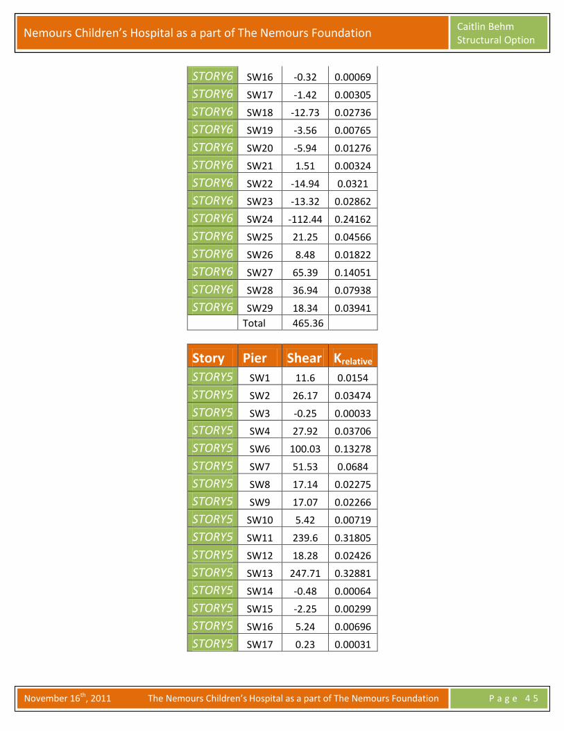
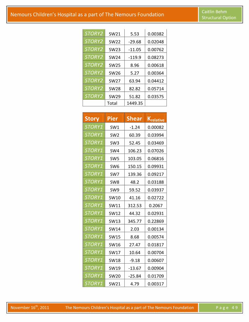
C.2 Hospital Quake Stiffness Tables
Story Pier Shear Krelative STORY8 SW6 24.84 0.65214
STORY8 SW7 -11.87 0.31163
STORY8 SW8 2.25 0.05907
STORY8 SW10 1.2 0.0315
STORY8 SW11 7.35 0.19296
STORY8 SW12 4.07 0.10685
STORY8 SW13 10.25 0.2691
STORY8 SW24 -6.35 0.16671
STORY8 SW26 5.52 0.14492
STORY8 SW28 2.14 0.05618
STORY8 SW29 -1.31 0.03439
Total 38.09
Story Pier Shear Krelative STORY7 SW1 0 0
STORY7 SW2 0 0
STORY7 SW3 0 0
STORY7 SW4 0 0
STORY7 SW6 26.38 0.2228
STORY7 SW7 -25.87 0.2185
STORY7 SW8 -7.78 0.06571
STORY7 SW9 -7.3 0.06166
STORY7 SW10 -13.43 0.11343
STORY7 SW11 101.98 0.86132
STORY7 SW12 -6 0.05068
STORY7 SW13 50.41 0.42576
Nemours Children’s Hospital as a part of The Nemours Foundation Caitlin Behm Structural Option
November 16th, 2011 The Nemours Children’s Hospital as a part of The Nemours Foundation P a g e 4 4
STORY7 SW14 0 0
STORY7 SW15 0 0
STORY7 SW16 0 0
STORY7 SW17 0 0
STORY7 SW18 0 0
STORY7 SW19 0.44 0.00372
STORY7 SW20 0 0
STORY7 SW21 0 0
STORY7 SW22 -5.24 0.04426
STORY7 SW23 -7.7 0.06503
STORY7 SW24 -68.86 0.58159
STORY7 SW25 11.17 0.09434
STORY7 SW26 7.11 0.06005
STORY7 SW27 44.24 0.37365
STORY7 SW28 14.95 0.12627
STORY7 SW29 3.9 0.03294
Total 118.4
Story Pier Shear Krelative STORY6 SW1 11.01 0.02366
STORY6 SW2 16.66 0.0358
STORY6 SW3 -7.08 0.01521
STORY6 SW4 9.15 0.01966
STORY6 SW6 69.1 0.14849
STORY6 SW7 16.17 0.03475
STORY6 SW8 10.79 0.02319
STORY6 SW9 9.7 0.02084
STORY6 SW10 0.93 0.002
STORY6 SW11 173.83 0.37354
STORY6 SW12 11.61 0.02495
STORY6 SW13 162.08 0.34829
STORY6 SW14 -1.1 0.00236
STORY6 SW15 -4.73 0.01016
Nemours Children’s Hospital as a part of The Nemours Foundation Caitlin Behm Structural Option
November 16th, 2011 The Nemours Children’s Hospital as a part of The Nemours Foundation P a g e 4 5
STORY6 SW16 -0.32 0.00069
STORY6 SW17 -1.42 0.00305
STORY6 SW18 -12.73 0.02736
STORY6 SW19 -3.56 0.00765
STORY6 SW20 -5.94 0.01276
STORY6 SW21 1.51 0.00324
STORY6 SW22 -14.94 0.0321
STORY6 SW23 -13.32 0.02862
STORY6 SW24 -112.44 0.24162
STORY6 SW25 21.25 0.04566
STORY6 SW26 8.48 0.01822
STORY6 SW27 65.39 0.14051
STORY6 SW28 36.94 0.07938
STORY6 SW29 18.34 0.03941
Total 465.36
Story Pier Shear Krelative STORY5 SW1 11.6 0.0154
STORY5 SW2 26.17 0.03474
STORY5 SW3 -0.25 0.00033
STORY5 SW4 27.92 0.03706
STORY5 SW6 100.03 0.13278
STORY5 SW7 51.53 0.0684
STORY5 SW8 17.14 0.02275
STORY5 SW9 17.07 0.02266
STORY5 SW10 5.42 0.00719
STORY5 SW11 239.6 0.31805
STORY5 SW12 18.28 0.02426
STORY5 SW13 247.71 0.32881
STORY5 SW14 -0.48 0.00064
STORY5 SW15 -2.25 0.00299
STORY5 SW16 5.24 0.00696
STORY5 SW17 0.23 0.00031

Nemours Children’s Hospital as a part of The Nemours Foundation Caitlin Behm Structural Option
November 16th, 2011 The Nemours Children’s Hospital as a part of The Nemours Foundation P a g e 4 6
STORY5 SW18 -14.83 0.01969
STORY5 SW19 -6.61 0.00877
STORY5 SW20 -12.5 0.01659
STORY5 SW21 3.16 0.00419
STORY5 SW22 -20.45 0.02715
STORY5 SW23 -13.66 0.01813
STORY5 SW24 -132.17 0.17544
STORY5 SW25 21.11 0.02802
STORY5 SW26 8.43 0.01119
STORY5 SW27 72.54 0.09629
STORY5 SW28 54.81 0.07276
STORY5 SW29 28.56 0.03791
Total 753.35
Story Pier Shear Krelative STORY4 SW1 9.68 0.00929
STORY4 SW2 33.76 0.03239
STORY4 SW3 8.54 0.00819
STORY4 SW4 48.25 0.04629
STORY4 SW5 41.19 0.03952
STORY4 SW6 125.19 0.1201
STORY4 SW7 83.75 0.08035
STORY4 SW8 22.98 0.02205
STORY4 SW9 22.79 0.02186
STORY4 SW10 9.84 0.00944
STORY4 SW11 295 0.28302
STORY4 SW12 23.63 0.02267
STORY4 SW13 320.18 0.30717
STORY4 SW14 -0.53 0.00051
STORY4 SW15 -1.68 0.00161
STORY4 SW16 9.23 0.00886
STORY4 SW17 0.22 0.00021
STORY4 SW18 -15.54 0.01491

Nemours Children’s Hospital as a part of The Nemours Foundation Caitlin Behm Structural Option
November 16th, 2011 The Nemours Children’s Hospital as a part of The Nemours Foundation P a g e 4 7
STORY4 SW19 -10.52 0.01009
STORY4 SW20 -20.39 0.01956
STORY4 SW21 4.33 0.00415
STORY4 SW22 -25.48 0.02444
STORY4 SW23 -14.55 0.01396
STORY4 SW24 -142.13 0.13636
STORY4 SW25 19.51 0.01872
STORY4 SW26 7.91 0.00759
STORY4 SW27 76.71 0.07359
STORY4 SW28 71.39 0.06849
STORY4 SW29 39.08 0.03749
Total 1042.34
Story Pier Shear Krelative STORY3 SW1 6.83 0.00536
STORY3 SW2 39.24 0.03079
STORY3 SW3 17.28 0.01356
STORY3 SW4 68.69 0.0539
STORY3 SW5 76.37 0.05993
STORY3 SW6 144.4 0.11331
STORY3 SW7 112.39 0.08819
STORY3 SW8 28.33 0.02223
STORY3 SW9 29.16 0.02288
STORY3 SW10 15.02 0.01179
STORY3 SW11 332.03 0.26055
STORY3 SW12 28.08 0.02203
STORY3 SW13 371.95 0.29188
STORY3 SW14 -0.42 0.00033
STORY3 SW15 -0.97 0.00076
STORY3 SW16 12.69 0.00996
STORY3 SW17 0.11 8.6E-05
STORY3 SW18 -15.13 0.01187
STORY3 SW19 -14.18 0.01113

Nemours Children’s Hospital as a part of The Nemours Foundation Caitlin Behm Structural Option
November 16th, 2011 The Nemours Children’s Hospital as a part of The Nemours Foundation P a g e 4 8
STORY3 SW20 -27.49 0.02157
STORY3 SW21 5.19 0.00407
STORY3 SW22 -29.21 0.02292
STORY3 SW23 -14.6 0.01146
STORY3 SW24 -140.35 0.11014
STORY3 SW25 16.28 0.01278
STORY3 SW26 6.94 0.00545
STORY3 SW27 75.79 0.05947
STORY3 SW28 82.32 0.0646
STORY3 SW29 47.6 0.03735
Total 1274.34
Story Pier Shear Krelative STORY2 SW1 2.77 0.00191
STORY2 SW2 46.99 0.03242
STORY2 SW3 31.25 0.02156
STORY2 SW4 93.07 0.06421
STORY2 SW5 93.5 0.06451
STORY2 SW6 157.14 0.10842
STORY2 SW7 136.97 0.0945
STORY2 SW8 35.84 0.02473
STORY2 SW9 41.56 0.02867
STORY2 SW10 24.83 0.01713
STORY2 SW11 343.41 0.23694
STORY2 SW12 34.01 0.02347
STORY2 SW13 391.56 0.27016
STORY2 SW14 -0.37 0.00026
STORY2 SW15 0.44 0.0003
STORY2 SW16 18.27 0.01261
STORY2 SW17 0.88 0.00061
STORY2 SW18 -12.97 0.00895
STORY2 SW19 -16.34 0.01127
STORY2 SW20 -31.17 0.02151
Nemours Children’s Hospital as a part of The Nemours Foundation Caitlin Behm Structural Option
November 16th, 2011 The Nemours Children’s Hospital as a part of The Nemours Foundation P a g e 4 9
STORY2 SW21 5.53 0.00382
STORY2 SW22 -29.68 0.02048
STORY2 SW23 -11.05 0.00762
STORY2 SW24 -119.9 0.08273
STORY2 SW25 8.96 0.00618
STORY2 SW26 5.27 0.00364
STORY2 SW27 63.94 0.04412
STORY2 SW28 82.82 0.05714
STORY2 SW29 51.82 0.03575
Total 1449.35
Story Pier Shear Krelative STORY1 SW1 -1.24 0.00082
STORY1 SW2 60.39 0.03994
STORY1 SW3 52.45 0.03469
STORY1 SW4 106.23 0.07026
STORY1 SW5 103.05 0.06816
STORY1 SW6 150.15 0.09931
STORY1 SW7 139.36 0.09217
STORY1 SW8 48.2 0.03188
STORY1 SW9 59.52 0.03937
STORY1 SW10 41.16 0.02722
STORY1 SW11 312.53 0.2067
STORY1 SW12 44.32 0.02931
STORY1 SW13 345.77 0.22869
STORY1 SW14 2.03 0.00134
STORY1 SW15 8.68 0.00574
STORY1 SW16 27.47 0.01817
STORY1 SW17 10.64 0.00704
STORY1 SW18 -9.18 0.00607
STORY1 SW19 -13.67 0.00904
STORY1 SW20 -25.84 0.01709
STORY1 SW21 4.79 0.00317
Nemours Children’s Hospital as a part of The Nemours Foundation Caitlin Behm Structural Option
November 16th, 2011 The Nemours Children’s Hospital as a part of The Nemours Foundation P a g e 5 0
STORY1 SW22 -21.1 0.01396
STORY1 SW23 -3.76 0.00249
STORY1 SW24 -84.32 0.05577
STORY1 SW25 1.43 0.00095
STORY1 SW26 3.54 0.00234
STORY1 SW27 39.05 0.02583
STORY1 SW28 65.5 0.04332
STORY1 SW29 44.83 0.02965
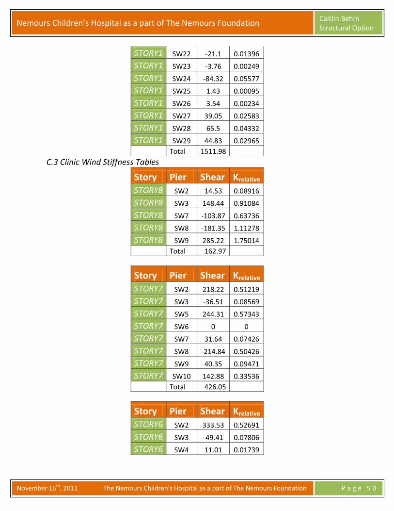
Total 1511.98
C.3 Clinic Wind Stiffness Tables
Story Pier Shear Krelative STORY8 SW2 14.53 0.08916
STORY8 SW3 148.44 0.91084
STORY8 SW7 -103.87 0.63736
STORY8 SW8 -181.35 1.11278
STORY8 SW9 285.22 1.75014
Total 162.97
Story Pier Shear Krelative STORY7 SW2 218.22 0.51219
STORY7 SW3 -36.51 0.08569
STORY7 SW5 244.31 0.57343
STORY7 SW6 0 0
STORY7 SW7 31.64 0.07426
STORY7 SW8 -214.84 0.50426
STORY7 SW9 40.35 0.09471
STORY7 SW10 142.88 0.33536
Total 426.05
Story Pier Shear Krelative STORY6 SW2 333.53 0.52691
STORY6 SW3 -49.41 0.07806
STORY6 SW4 11.01 0.01739

Nemours Children’s Hospital as a part of The Nemours Foundation Caitlin Behm Structural Option
November 16th, 2011 The Nemours Children’s Hospital as a part of The Nemours Foundation P a g e 5 1
STORY6 SW5 65.71 0.10381
STORY6 SW6 272.15 0.42994
STORY6 SW7 114.69 0.18119
STORY6 SW8 -107.24 0.16942
STORY6 SW9 -35.04 0.05536
STORY6 SW10 27.59 0.04359
Total 632.99
Story Pier Shear Krelative
STORY5 SW2 378.09 0.45227
STORY5 SW3 -3.28 0.00392
STORY5 SW4 10.7 0.0128
STORY5 SW5 97.61 0.11676
STORY5 SW6 352.87 0.4221
STORY5 SW7 80.69 0.09652
STORY5 SW8 -123.54 0.14778
STORY5 SW9 -9.18 0.01098
STORY5 SW10 52.03 0.06224
Total 835.99
Story Pier Shear Krelative STORY4 SW2 428.3 0.28932
STORY4 SW3 19.09 0.0129
STORY4 SW2 428.3 0.28932
STORY4 SW3 19.09 0.0129
STORY4 SW4 12.36 0.00835
STORY4 SW5 167.05 0.11284
STORY4 SW6 406.19 0.27438
STORY4 SW7 46.44 0.03137
STORY4 SW8 -164.96 0.11143
STORY4 SW9 24.22 0.01636
STORY4 SW10 94.3 0.0637
Total 1480.38

Nemours Children’s Hospital as a part of The Nemours Foundation Caitlin Behm Structural Option
November 16th, 2011 The Nemours Children’s Hospital as a part of The Nemours Foundation P a g e 5 2
Story Pier Shear Krelative STORY3 SW1 0 0
STORY3 SW2 495.76 0.40537
STORY3 SW3 19.29 0.01577
STORY3 SW4 4.05 0.00331
STORY3 SW5 234.57 0.1918
STORY3 SW6 469.32 0.38375
STORY3 SW7 27.09 0.02215
STORY3 SW8 -196.77 0.16089
STORY3 SW9 47.6 0.03892
STORY3 SW10 122.08 0.09982
Total 1222.99
Story Pier Shear Krelative STORY2 SW1 -307.8 0.21228
STORY2 SW2 903.21 0.62292
STORY2 SW3 85.02 0.05864
STORY2 SW4 39.17 0.02701
STORY2 SW5 302.79 0.20883
STORY2 SW6 427.56 0.29488
STORY2 SW7 51.38 0.03544
STORY2 SW8 -158.53 0.10933
STORY2 SW9 43.46 0.02997
STORY2 SW10 63.69 0.04393
Total 1449.95
Story Pier Shear Krelative
STORY1 SW1 -188.06 0.1137
STORY1 SW2 793.27 0.47961
STORY1 SW3 117.49 0.07103
STORY1 SW4 68.16 0.04121
STORY1 SW5 355.94 0.2152
STORY1 SW6 507.18 0.30664

Nemours Children’s Hospital as a part of The Nemours Foundation Caitlin Behm Structural Option
November 16th, 2011 The Nemours Children’s Hospital as a part of The Nemours Foundation P a g e 5 3
STORY1 SW7 13.99 0.00846
STORY1 SW8 -140.02 0.08466
STORY1 SW9 42.96 0.02597
STORY1 SW10 83.08 0.05023
Total 1653.99
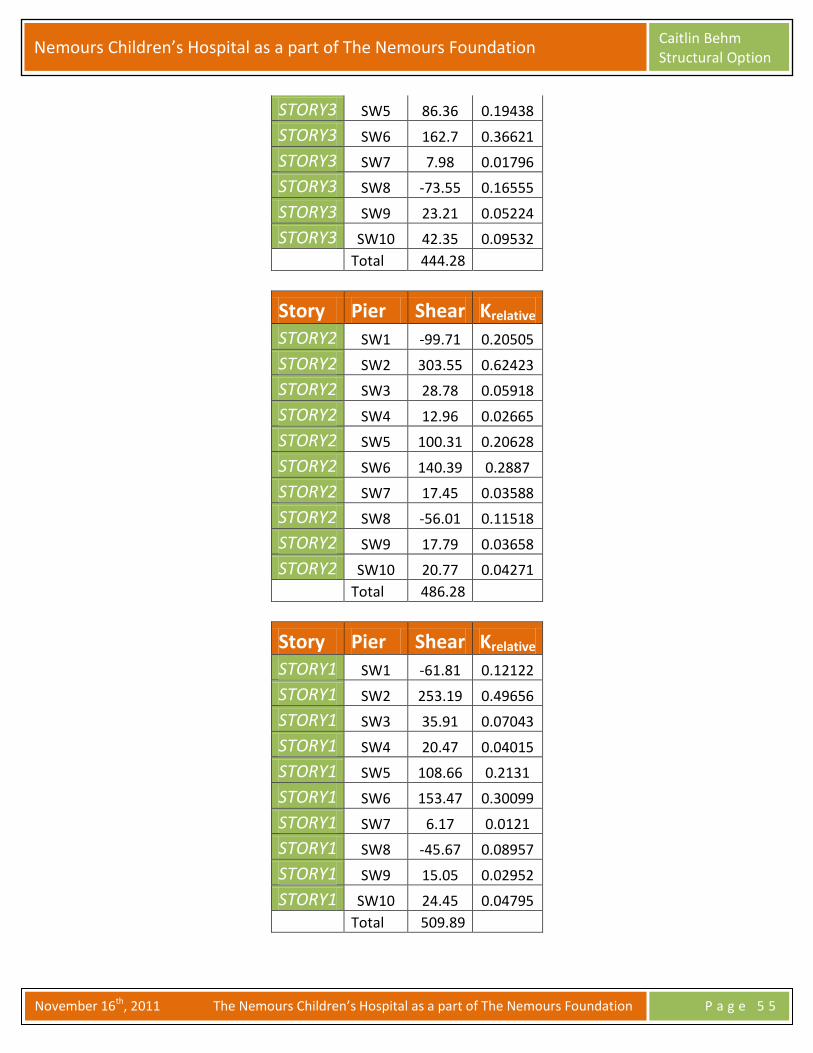
C.4 Clinic Quake Stiffness Tables
Story Pier Shear Krelative STORY8 SW2 2.68 0.11507
STORY8 SW3 20.61 0.88493
STORY8 SW7 -11.66 0.50064
STORY8 SW8 -31.97 1.37269
STORY8 SW9 43.63 1.87334
Total 23.29
Story Pier Shear Krelative STORY7 SW2 38.97 0.52956
STORY7 SW3 -4.28 0.05816
STORY7 SW5 38.9 0.5286
STORY7 SW6 0 0
STORY7 SW7 6.07 0.08248
STORY7 SW8 -47.47 0.64506
STORY7 SW9 15.04 0.20438
STORY7 SW10 26.36 0.3582
Total 73.59
Story Pier Shear Krelative STORY6 SW2 93.14 0.47138
STORY6 SW3 -1.9 0.00962
STORY6 SW4 1.94 0.00982
STORY6 SW5 27.07 0.137
STORY6 SW6 77.34 0.39142
STORY6 SW7 20.33 0.10289
STORY6 SW8 -42.94 0.21732

Nemours Children’s Hospital as a part of The Nemours Foundation Caitlin Behm Structural Option
November 16th, 2011 The Nemours Children’s Hospital as a part of The Nemours Foundation P a g e 5 4
STORY6 SW9 7.42 0.03755
STORY6 SW10 15.19 0.07688
Total 197.59
Story Pier Shear Krelative STORY5 SW2 127.51 0.42418
STORY5 SW3 7.06 0.02349
STORY5 SW4 3.87 0.01287
STORY5 SW5 46.86 0.15589
STORY5 SW6 115.3 0.38357
STORY5 SW7 15.75 0.0524
STORY5 SW8 -54.57 0.18154
STORY5 SW9 13.83 0.04601
STORY5 SW10 24.99 0.08313
Total 300.6
Story Pier Shear Krelative STORY4 SW2 156.38 0.40885
STORY4 SW3 11.28 0.02949
STORY4 SW4 4.93 0.01289
STORY4 SW5 68.38 0.17878
STORY4 SW6 141.52 0.37
STORY4 SW7 10.82 0.02829
STORY4 SW8 -66.94 0.17501
STORY4 SW9 20.02 0.05234
STORY4 SW10 36.1 0.09438
Total 382.49
Story Pier Shear Krelative STORY3 SW1 0 0
STORY3 SW2 182.51 0.4108
STORY3 SW3 10.18 0.02291
STORY3 SW4 2.54 0.00572
Nemours Children’s Hospital as a part of The Nemours Foundation Caitlin Behm Structural Option
November 16th, 2011 The Nemours Children’s Hospital as a part of The Nemours Foundation P a g e 5 5
STORY3 SW5 86.36 0.19438
STORY3 SW6 162.7 0.36621
STORY3 SW7 7.98 0.01796
STORY3 SW8 -73.55 0.16555
STORY3 SW9 23.21 0.05224
STORY3 SW10 42.35 0.09532
Total 444.28
Story Pier Shear Krelative
STORY2 SW1 -99.71 0.20505
STORY2 SW2 303.55 0.62423
STORY2 SW3 28.78 0.05918
STORY2 SW4 12.96 0.02665
STORY2 SW5 100.31 0.20628
STORY2 SW6 140.39 0.2887
STORY2 SW7 17.45 0.03588
STORY2 SW8 -56.01 0.11518
STORY2 SW9 17.79 0.03658
STORY2 SW10 20.77 0.04271
Total 486.28
Story Pier Shear Krelative STORY1 SW1 -61.81 0.12122
STORY1 SW2 253.19 0.49656
STORY1 SW3 35.91 0.07043
STORY1 SW4 20.47 0.04015
STORY1 SW5 108.66 0.2131
STORY1 SW6 153.47 0.30099
STORY1 SW7 6.17 0.0121
STORY1 SW8 -45.67 0.08957
STORY1 SW9 15.05 0.02952
STORY1 SW10 24.45 0.04795
Total 509.89
Nemours Children’s Hospital as a part of The Nemours Foundation Caitlin Behm Structural Option
November 16th, 2011 The Nemours Children’s Hospital as a part of The Nemours Foundation P a g e 5 6
Appendix D: Foundation Model Check D.1 Hand Calculations

Nemours Children’s Hospital as a part of The Nemours Foundation Caitlin Behm Structural Option
November 16th, 2011 The Nemours Children’s Hospital as a part of The Nemours Foundation P a g e 5 7
Appendix E: Member Check E.1 Hand Calculations