Embed Size (px)
Citation preview

NELES R-SERIES SEGMENT VALVEWAFER R1 AND FLANGED R21
Neles R-Series rotary control valve is a segment ball valve that provides outstanding control performance in a quarter-turn valve design. It is offered with a variety of trim options to satisfy most control applications, from standard and low Cv trims for general applications to a Q-Trim™ noise/cavitation trim option for fighting aerodynamic noise in steam or gas and preventing cavitation in liquids.
FEATURES
Integral body construction▫ Both flangeless and flanged R-Series valves feature
onepiece body construction with no flange rings,inserts, or end caps to create potential leak paths.
Rugged, self-adjusting metal seat▫ The size and durability of the R-Series segment valve
seat is in a class by itself. Carefully engineered seatdesign assures that flow does not directly impinge onthe seating surface, there by extending seat sealinglife. Energized pressure seal design ensures correctcontact between the seat and segment at all times.Seating capabilities are totally unaffected by pipelineforces, which assures more reliable valve operation.
Optional soft seat▫ Soft seats are also available for R-Series valves. These
seats extend the range of the R-Series to includeapplications where hard-chrome plating of the seg-ment is not suitable, such as acids and other very lowpH fluids. The design includes a carbon-filled PTFEseat inserted in a metal seat body of stainless steel ortitanium. For more details refer to the Seat designssection of this bulletin.
Protected bearings▫ Both trunnion bearings are located inside the valve
body. Having the lower shaft bearing inside the bodyprovides a larger bearing area, lower bearing loads,and longer bearing life. Locating the bearing outsideof the flow stream further enhances performance.
Economical▫ Low seat torque requirements combined with com-
pact actuator designs result in a lower cost total pack-age.
Low noise/Cavitation Q-Trim™ option▫ Liquid cavitation and aerodynamic noise, which can
be a problem at higher pressure drop ratios, arereduced with the patented Q-Trim™ option. This self-cleaning design handles contaminated flows (dirtysteam, river water, etc.) without plugging.
Reduced Cv trims
▫ The DN 25 / 1" size features five different segments(full area and four reduced trims). The reduced trimsextend the valve’s application range to low-flow high-accuracy services such as additive/coloring lines,pilot plants, etc.
Optional full titanium construction▫ A full titanium segment valve is available in sizes DN
25 - 250 / 1" through 10". This is an excellent solutionfor controlling seawater, organic crystallizing acids,and other fluids requiring corrosion resistant alloys.
3 R 20E
N · Issu
e 8/2001

M E T S O A U T O M A T I O N
- 2 -
12 3 14
1113
11
1
5
6
9 24
4225
4
4
4
15 20
1 29 30
16
26 10 18
ID-plate DN 100-400 / 4"-16"
ID-plate DN 25-80 / 1"-3"
Mfg-number
11
PARTS LIST
1) Alternative materials
Part NameBODY MATERIAL
Stainless steel Carbon steel Titanium
1 Body ASTM A351 gr. CF8M ASTM A216 gr. WCB ASTM B 367
3 Segment SIS 2324 + chromium / SIS 2324 / AISI 329 SIS 2324 + chromium / SIS 2324 / AISI 329 ASTM B 367
4 Seat Cobalt based alloy / PTFE 1) Cobalt based alloy / PTFE 1) ASTM B348 / PTFE 1)
5 Lock spring INCONEL 625 INCONEL 625 ASTM B348
6 Back seal SS + PTFE SS + PTFE TITANIUM + PTFE
9 Gland follower ASTM A351 gr. CF8M ASTM A351 gr. CF8M ASTM B348
10 Blind flange ASTM A351 gr. CF8M ASTM A351 gr. CF8M ASTM B348
11 Drive shaft SIS 2324 / AISI 329 SIS 2324 / AISI 329 ASTM B348
12 Shaft SIS 2324 / AISI 329 SIS 2324 / AISI 329 ASTM B348
13 Key SIS 2324 / AISI 329 SIS 2324 / AISI 329 SIS 2324 / AISI 329
14 Cylindrical pin SIS 2324 / AISI 329 SIS 2324 / AISI 329 ASTM B348
15 Bearing PTFE + SS net PTFE + SS net PVDF
16 Bearing PTFE + SS net PTFE + SS net PVDF
18 Sealing plate Graphite Graphite PTFE
20 Packing PTFE PTFE PTFE
24 Stud ISO 3506 A4-80 ISO 3506 A4-80 ASTM B348
25 Hexagon nut ISO 3506 A4-80 ISO 3506 A4-80 ASTM B348
26 Hexagon bolt ISO 3506 A4-80 ISO 3506 A4-80 ASTM B348
29 Identification plate AISI 304 AISI 304 AISI 304
42 Retainer plate AISI 316L AISI 316L Hastelloy C-276
EXPLODED VIEW
N E L E S R - S E R I E S S E G M E N T V A L V E W A F E R R 1 A N D F L A N G E D R 2 1
- 3 -
TypeReduced-bore quarter-turn valve- R1 and R11 mounted between flanges- R21 and R23 flanged
Pressure ratingsBodyDIN PN 40; ANSI 300TrimDIN PN 25; ANSI 150(Note the pressure/temperature curve)
SizesDN 25, 40, 50, 65, 80, 100, 150, 200, 250, 300, 350, 400Inch 1", 1 1/2", 2", 2 1/2", 3", 4", 6", 8", 10", 12", 14", 16"
Face-to-face dimensionsR1 special.R11, R21 according to ISA S75.04 and IEC/DIN 534-3-2.R23 according to ASME B16.10 short pattern.
Temperature range-40˚C ... +250˚C / -40…+480°F.
Inherent flow characteristicEqual percentage.
Fire safetyR21 according to BS6755/API 607, 4th edition.
TightnessTightness is tested in the direction by the arrow, see page 4,according to ISO 5208. The standard tightness of a metal-seated segment valve is 10 x ISO 5208 Rate D. This tightnesscorresponds to 1/100 of max seat leakage allowed by ANSI/FCI 70.2 Class IV.
Valve pressure and leak testAll valves manufactured by Metso Automation undergo pres-sure testing. The test pressure of an R-series valve body is1.5 x the pressure rating and the test pressure of a seat is1.1 x the maximum permissible shut-off pressure. The testmedium is water containing a corrosion inhibitor.
Maximum allowable leakage
Size DN / inch Metal seat Soft seat
25 / 1 1.50 ml/min 0.15 ml/min
40 / 1 1/2 2.40 ml/min 0.24 ml/min
50 / 2 3.00 ml/min 0.30 ml/min
65 / 2 1/2 3.90 ml/min 0.39 ml/min
80 / 3 4.80 ml/min 0.48 ml/min
100 / 4 6.00 ml/min 0.60 ml/min
150 / 6 9.00 ml/min 0.90 ml/min
200 / 8 12.00 ml/min 1.20 ml/min
250 / 10 15.00 ml/min 1.50 ml/min
300 / 12 18.00 ml/min 1.80 ml/min
350 / 14 21.00 ml/min 2.10 ml/min
400 / 16 24.00 ml/min 2.40 ml/min
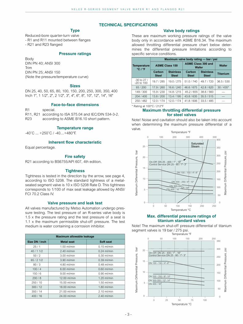
TECHNICAL SPECIFICATIONS
Maximum throttling differential pressurefor steel valves
Note! Noise and cavitation should also be taken into accountwhen determining the maximum pressure differential of avalve.
Max. differential pressure ratings of titanium standard valves
Note! The maximum shut-off pressure differential of titaniumsegment valves is 19 bar / 275 psi.
Valve body ratingsThese are maximum working pressure ratings of the valvebody only in accordance with ASME B16.34. The maximumallowed throttling differential pressure chart below deter-mines the differential pressure limitations according tospecific service conditions.
* Rating at 100°C / 212°F
Temperature°C / °F
Maximum valve body rating — bar / psi
ASME Class 150 ASME Class 300 and
Wafer Wafer
Carbon Steel
Stainless Steel
Carbon Steel
Stainless Steel
Titanium
-30 to 27 /-20 to 100 19.7 / 285 19.0 / 275 51.0 / 740 49.7 / 720 36.5 / 530
93 / 200 17.9 / 260 16.6 / 240 46.6 / 675 42.8 / 620 30 / 435*
149 / 300 15.9 / 230 14.8 / 215 45.2 / 655 38.6 / 560 —
204 / 400 13.8 / 200 13.4 / 195 43.8 / 635 35.5 / 515 —
250 / 482 12.0 / 174 12.0 / 174 41.8 / 606 33.5 / 485 —
0 100 200 300 400 500
0 50 100 150 200 250
400
350
300
250
200
150
100
50
0
25
20
15
10
5
DN 100 - 150 / 4"- 6"
DN 300-350 / 12"- 14"
DN 200 - 250 / 8"- 10"
0
DN 400 / 16"
Temperature °C
Temperature °F
Max
imum
Diff
eren
tial P
ress
ure,
bar
Max
imum
Diff
eren
tial P
ress
ure,
psi
SaturatedSteam
On-Off: DN 25 - 400 / 1" - 16"Control Service DN 25 - 80 / 1"- 3"
0 25 50 75 100
0 50 100 150 200 250350
300
250
200
150
100
50
0
20
15
10
5 DN 400 / 16"
DN 200 - 250 / 8"- 10"
DN 300-350 / 12"- 14"
DN 100 - 150 / 4"- 6"
0
Temperature °C
Temperature °F
Max
imum
Diff
eren
tial P
ress
ure,
bar
Max
imum
Diff
eren
tial P
ress
ure,
psi
On-Off: DN 25 - 400 / 1" - 16"Control Service DN 25 - 80 / 1"- 3"

M E T S O A U T O M A T I O N
- 4 -
Maximum Cv and resistance coefficients for R-series valves
1) 100% corresponds to a 95˚ turning angle2) For Q-R-valves, 100% corresponds to a 90˚ turning angle
Valvesize DN
Valvesize inch
Metal-seated valve Soft-seated valveStandard valve R2-S-valve Q-R-valve Standard valve
Cv 100%1) ξ 100%1) Cv 70˚ ξ 70˚ Cv 100%2) Cv 100%1) ξ 100%1)
25 1 45 0.41 – – – 21 1.8340 1 1/2 110 0.45 – – – 61 1.4750 2 180 0.41 – – 47 110 1.1065 2 1/2 280 0.49 – – 96 215 0.8380 3 420 0.50 125 5.5 160 340 0.76100 4 620 0.56 200 5.1 250 520 0.79150 6 1260 0.68 370 8.1 540 1070 0.94200 8 2030 0.83 600 9.3 880 1760 1.10250 10 3210 0.81 900 10.3 1510 2830 1.04300 12 4490 0.86 – – 2140 4080 1.04350 14 6440 0.77 – – 3160 5750 0.97400 16 8510 0.76 – – 4180 7630 0.94
SEATS DESIGNSD Metal seat
B Metal seat
K Metal seat
U Metal seat
Soft seat (PTFE + C25%)
E Non-tight metal seat
Seat: Stainless steel + cobalt based hard facing
Spring: Inconel 625
Seat seal: PTFE coated Viton O-ring
Temp. Range: -40 °C... +250 °C / - 40 °F …+480 °F
Service: Control, ANSI Class IV tight
Seat: 317 SS + Cobalt based hard facing
Spring: Inconel 625
Seat seal: Filled PTFE lipseal / Elgiloy spring
Temp. Range: -40 °C... +250 °C/ - 40 °F …+480 °F
Service: General service
Seat: 316 SS + Cobalt based hard facing
Spring: Inconel 625
Seat seal: Filled PTFE lipseal / Elgiloy spring
Temp. Range: -40 °C... +250 °C / - 40 °F …+480 °F
Service: General service
Seat: Titanium
Spring: Titanium
Seat seal: Virgin PTFE lipseal / Titanium spring
Temp. Range: -40 °C... +120 °C / - 40 °F …+250 °F
Service: Specially for chloride applications except dry chlorine gas.
Code Seat body Spring Seat seal Back seal
T2 316 SS Inconel 625 Filled PTFE PTFE
T3 317 SS Inconel 625 Filled PTFE PTFE
T4 304 SS Inconel 625 Filled PTFE PTFE
T5 Titanium Titanium Virgin PTFE PTFE
T6 Hastelloy Inconel 625 Filled PTFE Hastel. spring
T7 UNS S31254 Inconel 625 Virgin PTFE Viton GF
Temperature range for T2, T3, T4: -40 °C... +250 °C / -40 °F …+480 °FTemperature range for T5, T6: -40 °C... +120 °C / -40 °F …+250 °FTemperature range for T7: -40 °C... +200 °C / -40 °F …+390 °F
Seat: Cobalt based alloy
Temp. Range: -40 °C... +250 °C / - 40 °F …+480 °F
Service: Extremely erosive applications, non-tight.
NOTE ! Flow direction arrow is reversed.
D Metal seat
Flow direction
B Metal seat
Flow direction
K Metal seat
Flow direction
U Metal seat
Flow direction
Soft seat
Flow direction
E Non-tight metal seat
Flow direction
N E L E S R - S E R I E S S E G M E N T V A L V E W A F E R R 1 A N D F L A N G E D R 2 1
- 5 -
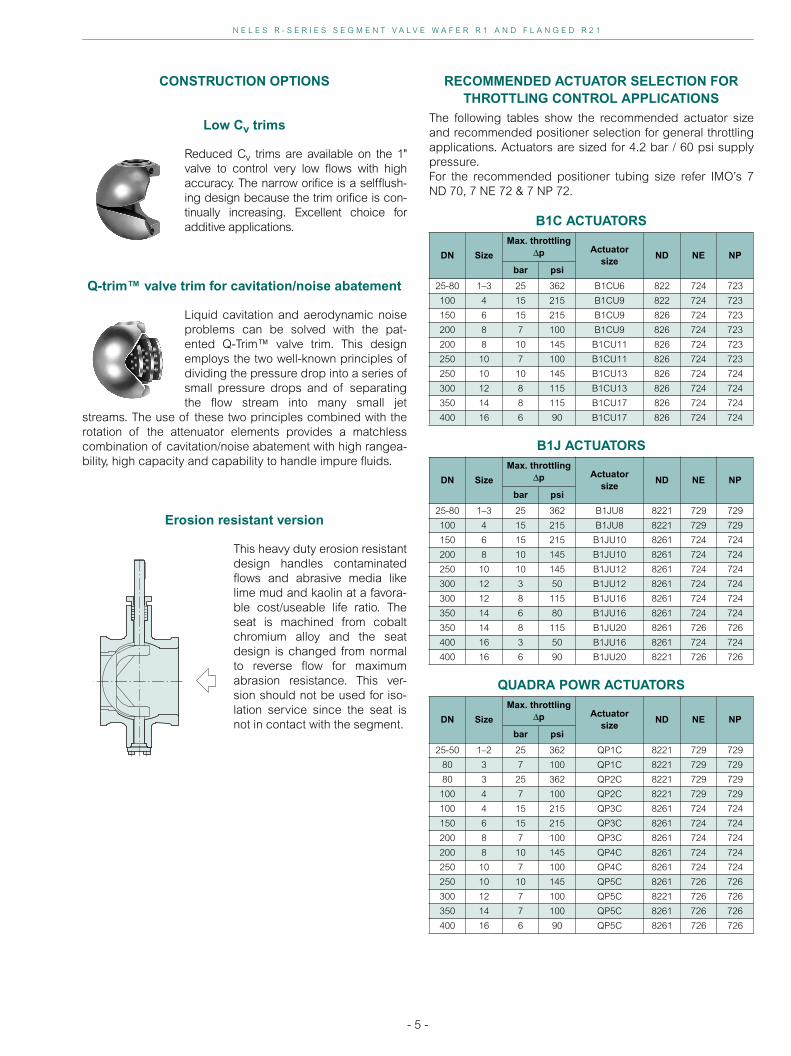
CONSTRUCTION OPTIONS
Low Cv trims
Reduced Cv trims are available on the 1"valve to control very low flows with highaccuracy. The narrow orifice is a selfflush-ing design because the trim orifice is con-tinually increasing. Excellent choice foradditive applications.
Q-trim™ valve trim for cavitation/noise abatement
Liquid cavitation and aerodynamic noiseproblems can be solved with the pat-ented Q-Trim™ valve trim. This designemploys the two well-known principles ofdividing the pressure drop into a series ofsmall pressure drops and of separatingthe flow stream into many small jet
streams. The use of these two principles combined with therotation of the attenuator elements provides a matchlesscombination of cavitation/noise abatement with high rangea-bility, high capacity and capability to handle impure fluids.
Erosion resistant version
This heavy duty erosion resistantdesign handles contaminatedflows and abrasive media likelime mud and kaolin at a favora-ble cost/useable life ratio. Theseat is machined from cobaltchromium alloy and the seatdesign is changed from normalto reverse flow for maximumabrasion resistance. This ver-sion should not be used for iso-lation service since the seat isnot in contact with the segment.
RECOMMENDED ACTUATOR SELECTION FOR THROTTLING CONTROL APPLICATIONS
The following tables show the recommended actuator sizeand recommended positioner selection for general throttlingapplications. Actuators are sized for 4.2 bar / 60 psi supplypressure.For the recommended positioner tubing size refer IMO’s 7ND 70, 7 NE 72 & 7 NP 72.
B1C ACTUATORS
B1J ACTUATORS
QUADRA POWR ACTUATORS
DN Size
Max. throttling∆p Actuator
sizeND NE NP
bar psi
25-80 1–3 25 362 B1CU6 822 724 723
100 4 15 215 B1CU9 822 724 723
150 6 15 215 B1CU9 826 724 723
200 8 7 100 B1CU9 826 724 723
200 8 10 145 B1CU11 826 724 723
250 10 7 100 B1CU11 826 724 723
250 10 10 145 B1CU13 826 724 724
300 12 8 115 B1CU13 826 724 724
350 14 8 115 B1CU17 826 724 724
400 16 6 90 B1CU17 826 724 724
DN Size
Max. throttling∆p Actuator
sizeND NE NP
bar psi
25-80 1–3 25 362 B1JU8 8221 729 729
100 4 15 215 B1JU8 8221 729 729
150 6 15 215 B1JU10 8261 724 724
200 8 10 145 B1JU10 8261 724 724
250 10 10 145 B1JU12 8261 724 724
300 12 3 50 B1JU12 8261 724 724
300 12 8 115 B1JU16 8261 724 724
350 14 6 80 B1JU16 8261 724 724
350 14 8 115 B1JU20 8261 726 726
400 16 3 50 B1JU16 8261 724 724
400 16 6 90 B1JU20 8221 726 726
DN Size
Max. throttling∆p Actuator
sizeND NE NP
bar psi
25-50 1–2 25 362 QP1C 8221 729 729
80 3 7 100 QP1C 8221 729 729
80 3 25 362 QP2C 8221 729 729
100 4 7 100 QP2C 8221 729 729
100 4 15 215 QP3C 8261 724 724
150 6 15 215 QP3C 8261 724 724
200 8 7 100 QP3C 8261 724 724
200 8 10 145 QP4C 8261 724 724
250 10 7 100 QP4C 8261 724 724
250 10 10 145 QP5C 8261 726 726
300 12 7 100 QP5C 8221 726 726
350 14 7 100 QP5C 8261 726 726
400 16 6 90 QP5C 8261 726 726
M E T S O A U T O M A T I O N
- 6 -
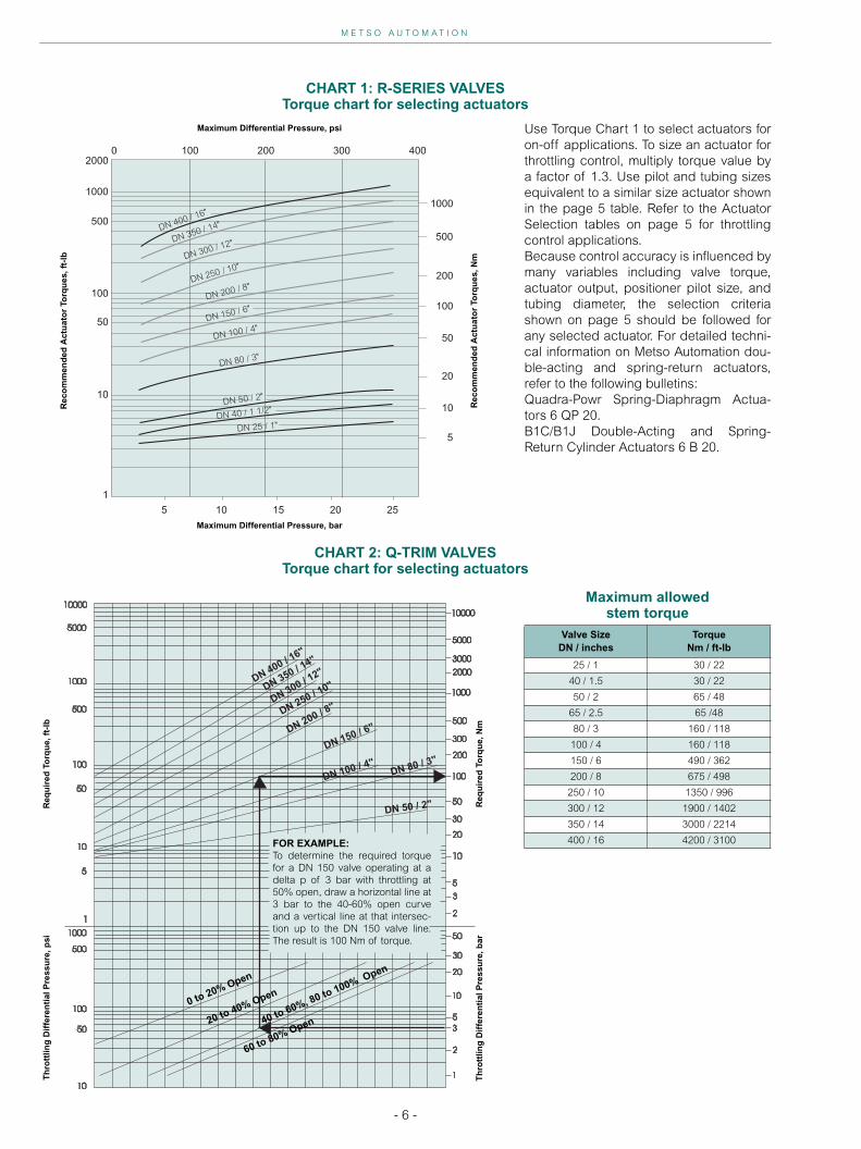
Maximum allowed stem torque
Valve SizeDN / inches
TorqueNm / ft-lb
25 / 1 30 / 22
40 / 1.5 30 / 22
50 / 2 65 / 48
65 / 2.5 65 /48
80 / 3 160 / 118
100 / 4 160 / 118
150 / 6 490 / 362
200 / 8 675 / 498
250 / 10 1350 / 996
300 / 12 1900 / 1402
350 / 14 3000 / 2214
400 / 16 4200 / 3100
Use Torque Chart 1 to select actuators foron-off applications. To size an actuator forthrottling control, multiply torque value bya factor of 1.3. Use pilot and tubing sizesequivalent to a similar size actuator shownin the page 5 table. Refer to the ActuatorSelection tables on page 5 for throttlingcontrol applications.Because control accuracy is influenced bymany variables including valve torque,actuator output, positioner pilot size, andtubing diameter, the selection criteriashown on page 5 should be followed forany selected actuator. For detailed techni-cal information on Metso Automation dou-ble-acting and spring-return actuators,refer to the following bulletins:Quadra-Powr Spring-Diaphragm Actua-tors 6 QP 20.B1C/B1J Double-Acting and Spring-Return Cylinder Actuators 6 B 20.
CHART 1: R-SERIES VALVESTorque chart for selecting actuators
CHART 2: Q-TRIM VALVESTorque chart for selecting actuators
DN 400 / 16"
DN 250 / 10"
DN 80 / 3"
DN 200 / 8"
DN 100 / 4"DN 150 / 6"
DN 300 / 12"DN 350 / 14"
DN 50 / 2"
DN 40 / 1 1/2"
DN 25 / 1"
0 100 200 300 400
1000
500
200
100
50
20
10
5
252015105
1000
500
100
50
10
1
2000
Maximum Differential Pressure, bar
Maximum Differential Pressure, psi
Rec
om
men
ded
Act
uat
or
Torq
ues
, Nm
Rec
om
men
ded
Act
uat
or
Torq
ues
, ft-
lb
FOR EXAMPLE:To determine the required torquefor a DN 150 valve operating at adelta p of 3 bar with throttling at50% open, draw a horizontal line at3 bar to the 40-60% open curveand a vertical line at that intersec-tion up to the DN 150 valve line.The result is 100 Nm of torque.
0 to 20% Open
40 to 60%, 80 to 100% Open
20 to 40% Open
60 to 80% Open
Req
uir
ed T
orq
ue,
Nm
Req
uir
ed T
orq
ue,
ft-
lb
Th
rott
ling
Dif
fere
nti
al P
ress
ure
, bar
Th
rott
ling
Dif
fere
nti
al P
ress
ure
, psi

N E L E S R - S E R I E S S E G M E N T V A L V E W A F E R R 1 A N D F L A N G E D R 2 1
- 7 -
R1/R11
DN
MAIN DIMENSIONS, mm SHAFT DIMENSIONS, mm
DR1 R11 R1 R11 R1/R11LA (KEY) R1/R11LE (SPLINES)
A A1 A A1 B C S T U UNC kg kg O E R K M P N Dl E R K N1 P1/DIN5480
25 33 / 38* 50 25 102 51 64 57 70 - 3/8 2,5 3,3 15 144 70 119 4.76 17 25 15 175 100 120 20 W14x1x12
40 49 60 25 114 57 82 63 70 - 3/8 3,5 5,1 15 151 71 125 4.76 17 25 15 181 101 125 20 W14x1x12
50 60 75 32 124 62 100 92 70 - 3/8 5 7,3 15 170 70 145 4.76 17 25 15 200 100 145 20 W14x1x12
65 73 100 50 118 99 70 - 3/8 8 15 175 70 150 4.76 17 25 15 206 101 150 20 W14x1x12
80 89 100 45 165 83 131 108 90 - 1/2 9 13,4 20 196 79 162 4.76 22.2 35 20 227 110 162 20 W14x1x12
100 113 115 50 194 97 158 117 90 - 1/2 11 17 20 205 80 170 4.76 22.2 35 20 236 111 170 20 W18x1x16
150 164 160 65 229 115 216 177 110 32 1/2 26 35 25 295 110 255 6.35 27.8 46 25 300 115 250 25 W25x1x24
200 205 200 80 243 122 268 200 130 32 1/2 48 55 25/30 346 140 286 6.35 27.8 46 30 341 135 285 25 W25x1x24
250 259 240 92 297 149 326 252 130 32 1/2 78 92 35 390 141 329 9.52 39.1 58 35 396 146 330 35 W34x1x32
SIZE
MAIN DIMENSIONS, inch SHAFT DIMENSIONS, inch
DR1 R11 R1 R11 R1/R11LA (KEY) R1/R11LE (SPLINES)
A A1 A A1 B C S T U UNC lbs lbs O E R K M P N Dl E R K N1 P1/DIN5480
1 1.30 / 1.49* 1.97 0.98 4.02 2.01 2.52 2.24 2.76 - 3/8 6 7 0.59 5.67 2.76 4.69 0.19 0.67 0.98 0.59 6.89 3.94 4.72 0.79 W14x1x12
1.5 1.93 2.36 0.98 4.49 2.24 3.23 2.48 2.76 - 3/8 8 11 0.59 5.94 2.80 4.92 0.19 0.67 0.98 0.59 7.13 3.98 4.92 0.79 W14x1x12
2 2.36 2.95 1.26 4.88 2.44 3.94 3.62 2.76 - 3/8 11 16 0.59 6.69 2.76 5.71 0.19 0.67 0.98 0.59 7.87 3.94 5.71 0.79 W14x1x12
2.5 2.87 3.94 1.97 4.65 3.90 2.76 - 3/8 18 0.59 6.89 2.76 5.91 0.19 0.67 0.98 0.59 8.11 3.98 5.91 0.79 W14x1x12
3 3.50 3.94 1.77 6.50 3.27 5.16 4.25 3.54 - 1/2 20 29 0.79 7.72 3.11 6.38 0.19 0.87 1.38 0.79 8.94 4.33 6.38 0.79 W14x1x12
4 4.45 4.53 1.97 7.64 3.82 6.22 4.61 3.54 - 1/2 24 37 0.79 8.07 3.15 6.69 0.19 0.87 1.38 0.79 9.29 4.37 6.69 0.79 W18x1x16
6 6.46 6.30 2.56 9.02 4.53 8.50 6.97 4.33 1.26 1/2 57 77 0.98 11.61 4.33 10.04 0.25 1.09 1.81 0.98 11.81 4.53 9.84 0.98 W25x1x24
8 8.07 7.87 3.15 9.57 4.80 10.55 7.87 5.12 1.26 1/2 106 121 0.98/1.18 13.62 5.51 11.26 0.25 1.09 1.81 1.18 13.43 5.31 11.22 0.98 W25x1x24
10 10.20 9.45 3.62 11.69 5.87 12.83 9.92 5.12 1.26 1/2 172 202 1.38 15.35 5.55 12.95 0.37 1.54 2.28 1.38 15.59 5.75 12.99 1.38 W34x1x32
* Low capacity segment max Cv 0.5, 1.5 or 15
DNDN
K
CCEE
Ø D
SSSS
Ø B
(KEY)(KEY)(SPLINES)(SPLINES)
1
AA11
UU UUM
TT
DN 25...100 / 1"-4" DN 150...250 / 6"-10"
MM
R1LER1LER1LAR1LA
N1N1 NN
P PP
OO OO
AA
R
P
Cv 100% of 95 degree travel.The pressure rating of the valve body is ASME Class 300The allowed pressure differential in closed position is 25 bar/360 psi.
R1/R11
DIMENSIONS

M E T S O A U T O M A T I O N
- 8 -
R21/R23
DN
MAIN DIMESIONS, mm SHAFT DIMESIONS, mm FLANGE DIMESIONS, mm
R21 R23C R23DU
UNC
R21/R23_A (KEY) R21/R23_E (SPLINES) R21/R23C ASME 150 R21/R23D ASME 300
D A A A C S T O E R K M P N O1 E R K N1 P1/DIN5480 B b1 fR21C
kgR23C
kgB b1 f
R21D kg
R23D kg
25 33/38* 102 57 70 – 3/8 15 144 70 119 4.76 17 25 15 175 100 120 20 W14x1x12 108 14.5 1.6 3.5 124 17.5 1.6 5
40 49 114 63 70 – 3/8 15 151 71 125 4.76 17 25 15 181 101 125 20 W14x1x12 127 14.5 1.6 5 156 21 1.6 8
50 60 124 178 216 92 70 – 3/8 15 170 70 145 4.76 17 25 15 200 100 145 20 W14x1x12 152 16 1.6 8 17 165 22.5 1.6 10 24
65 73 145 99 70 – 3/8 15 175 70 150 4.76 17 25 15 206 101 150 20 W14x1x12 178 17.5 1.6 11 191 25.5 1.6 14
80 89 165 208 282 108 90 – 1/2 20 196 79 162 4.76 22.2 35 20 227 110 162 20 W14x1x12 191 19.5 1.6 15 25 210 29 1.6 20 36
100 113 194 224 305 117 90 – 1/2 20 205 80 170 4.76 22.2 35 20 236 111 170 20 W18x1x16 229 24 1.6 23 35 254 32 1.6 31 50
150 164 229 267 403 177 110 32 1/2 25 295 110 255 6.35 27.8 46 25 300 115 255 25 W25x1x24 279 25.5 1.6 45 77 318 37 1.6 60 100
200 205 243 298 419 200 130 32 1/2 25/30 346 140 286 6.35 27.8 46 30 341 135 286 30 W25x1x24 343 29 1.6 70 107 381 41.5 1.6 95 150
250 259 297 252 130 32 1/2 35 390 140 329 9.52 39.1 58 35 396 146 330 35 W34x1x32 406 30.5 1.6 105 445 48 1.6 140
300 300 338 270 160 40 5/8 40 462 165 387 9.52 44.2 68 40 452 155 387 35 W34x1x32 483 32 1.6 155 520 51 1.6 205
350 350 400 310 160 40 5/8 45 478 165 403 12.7 50.4 80 45 468 155 403 35 W34x1x32 534 35 1.6 210 584 54 1.6 280
400 400 400 355 160 55 3/4 50 532 178 454 12.7 55.5 90 50 529 175 454 35 W34x1x32 597 37 1.6 290 648 57 1.6 380
MAIN DIMESIONS, inch SHAFT DIMESIONS, inch FLANGE DIMESIONS, inch
SIZE D
R21 R23C R23DU
UNC
R21/R23_A (KEY) R21/R23_E (SPLINES) R21/R23C ASME 150 R21/R23D ASME 300
A A A C S T O E R K M P N O1 E R K N1 P1/DIN5480 B b1 fR21C lbs
R23C lbs
B b1 fR21D lbs
R23D lbs
1 1.30/1.49* 4.02 2.24 2.76 – 3/8 0.59 5.67 2.76 4.69 0.19 0.67 0.98 0.59 6.89 3.94 4.72 0.79 W14x1x12 4.25 0.57 0.06 8 4.88 0.69 0.06 11
1.5 1.93 4.49 2.48 2.76 – 3/8 0.59 5.94 2.80 4.92 0.19 0.67 0.98 0.59 7.13 3.98 4.92 0.79 W14x1x12 5.00 0.57 0.06 11 6.14 0.83 0.06 18
2 2.36 4.88 7.01 8.50 3.62 2.76 – 3/8 0.59 6.69 2.76 5.71 0.19 0.67 0.98 0.59 7.87 3.94 5.71 0.79 W14x1x12 5.98 0.63 0.06 18 37 6.50 0.89 0.06 22 53
2.5 2.87 5.71 3.90 2.76 – 3/8 0.59 6.89 2.76 5.91 0.19 0.67 0.98 0.59 8.11 3.98 5.91 0.79 W14x1x12 7.01 0.69 0.06 24 7.52 1.00 0.06 31
3 3.50 6.50 8.19 11.10 4.25 3.54 – 1/2 0.79 7.72 3.11 6.38 0.19 0.87 1.38 0.79 8.94 4.33 6.38 0.79 W14x1x12 7.52 0.77 0.06 33 55 8.27 1.14 0.06 44 79
4 4.45 7.64 8.82 12.01 4.61 3.54 – 1/2 0.79 8.07 3.15 6.69 0.19 0.87 1.38 0.79 9.29 4.37 6.69 0.79 W18x1x16 9.02 0.94 0.06 51 77 10.00 1.26 0.06 68 110
6 6.46 9.02 10.51 15.87 6.97 4.33 1.26 1/2 0.98 11.61 4.33 10.04 0.25 1.09 1.81 0.98 11.81 4.53 10.04 0.98 W25x1x24 10.98 1.00 0.06 99 169 12.52 1.46 0.06 132 220
8 8.07 9.57 11.73 16.50 7.87 5.12 1.26 1/2 0.89/1.18* 13.62 5.51 11.26 0.25 1.09 1.81 1.18 13.43 5.31 11.26 1.18 W25x1x24 13.50 1.14 0.06 154 235 15.00 1.63 0.06 209 330
10 10.20 11.69 9.92 5.12 1.26 1/2 1.38 15.35 5.51 12.95 0.37 1.54 2.28 1.38 15.59 5.75 12.99 1.38 W34x1x32 15.98 1.20 0.06 231 17.52 1.89 0.06 308
12 11.81 13.31 10.63 6.30 1.57 5/8 1.57 18.19 6.50 15.24 0.37 1.74 2.68 1.57 17.80 6.10 15.24 1.38 W34x1x32 19.02 1.26 0.06 341 20.47 2.01 0.06 451
14 13.78 15.75 12.20 6.30 1.57 5/8 1.77 18.82 6.50 15.87 0.50 1.98 3.15 1.77 18.43 6.10 15.87 1.38 W34x1x32 21.02 1.38 0.06 462 22.99 2.13 0.06 616
16 15.75 15.75 13.98 6.30 2.17 3/4 1.97 20.94 7.01 17.87 0.50 2.19 3.54 1.97 20.83 6.89 17.87 1.38 W34x1x32 23.50 1.46 0.06 638 25.51 2.24 0.06 836
DN
KCCEE
Ø DØ B
SSSS
MM
UU
DN25...100DN25...100 / 1"-4"
(KEY)(SPLINES) 11
11
UU
MM
TT
DN150...400DN150...400 / 6"-16"
R21_E R21_A
NNNN
PP PP
O1O1 O
f b1
AA
OO(KEY)
R21_A200
Ø 25 / 1" Ø 30 /1.18"
R
R21/R23

N E L E S R - S E R I E S S E G M E N T V A L V E W A F E R R 1 A N D F L A N G E D R 2 1
- 9 -
*Low capacity segment: Max Cv 0.5, 1.5, 5 or 15Cv 100% of 95 degree travel. The allowed pressure differential in closed position is 25 bar / 370 psi.
DN
FLANGE DIMESIONS. mm
R21J PN 10 R21K PN 16 R21L PN 25 R21M PN 40
B b1 f kg B b1 f kg B b1 f kg B b1 f kg
25 115 18 2 4.5 115 18 2 4.5 115 18 2 4.5 115 18 2 4.5
40 150 18 3 7 150 18 3 7 150 18 3 7 150 18 3 7
50 165 20 3 10 165 20 3 10 165 20 3 10 165 20 3 10
65 185 18 3 12 185 18 3 12 185 22 3 13 185 22 3 13
80 200 20 3 16 200 20 3 16 200 24 3 17 200 24 3 17
100 220 20 3 21 220 20 3 21 235 24 3 24 235 24 3 24
150 285 22 3 45 285 22 3 45 300 28 3 50 300 28 3 50
200 340 24 3 65 340 24 3 65 360 30 3 75 375 34 3 85
250 395 26 3 100 405 26 3 105 425 32 3 115 450 38 3 130
300 445 26 4 135 460 28 4 145 485 34 4 160 515 42 4 185
350 505 26 4 185 520 30 4 195 555 38 4 225 580 46 4 260
400 565 26 4 250 580 32 4 270 620 40 4 310 660 50 4 370
SIZE
FLANGE DIMESIONS, inch
R21J PN 10 R21K PN 16 R21L PN 25 R21M PN 40
B b1 f lbs B b1 f lbs B b1 f lbs B b1 f lbs
1 4.53 0.71 0.08 10 4.53 0.71 0.08 10 4.53 0.71 0.08 10 4.53 0.71 0.08 10
1.5 5.91 0.71 0.12 15 5.91 0.71 0.12 15 5.91 0.71 0.12 15 5.91 0.71 0.12 15
2 6.50 0.79 0.12 22 6.50 0.79 0.12 22 6.50 0.79 0.12 22 6.50 0.79 0.12 22
2.5 7.28 0.71 0.12 26 7.28 0.71 0.12 26 7.28 0.87 0.12 29 7.28 0.87 0.12 29
3 7.87 0.79 0.12 35 7.87 0.79 0.12 35 7.87 0.94 0.12 37 7.87 0.94 0.12 37
4 8.66 0.79 0.12 46 8.66 0.79 0.12 46 9.25 0.94 0.12 53 9.25 0.94 0.12 53
6 11.22 0.87 0.12 99 11.22 0.87 0.12 99 11.81 1.10 0.12 110 11.81 1.10 0.12 110
8 13.39 0.94 0.12 143 13.39 0.94 0.12 143 14.17 1.18 0.12 165 14.76 1.34 0.12 187
10 15.55 1.02 0.12 220 15.94 1.02 0.12 231 16.73 1.26 0.12 253 17.72 1.50 0.12 286
12 17.52 1.02 0.16 297 18.11 1.10 0.16 319 19.09 1.34 0.16 352 20.28 1.65 0.16 407
14 19.88 1.02 0.16 407 20.47 1.18 0.16 429 21.85 1.50 0.16 495 22.83 1.81 0.16 572
16 22.24 1.02 0.16 550 22.83 1.26 0.16 594 24.41 1.57 0.16 682 25.98 1.97 0.16 814
DN
FLANGE DIMENSIONS, mm
R21R JIS 10K R21S JIS 16K R21T JIS 20K
B b1 f kg B b1 f kg B b1 f kg
25 125 14 1 5 125 14 1 5 125 16 1 5
40 140 16 2 6 140 16 2 6 140 18 2 7
50 155 16 2 8 155 16 2 8 155 18 2 8
65 175 18 2 10 175 18 2 10 175 20 2 12
80 185 18 2 14 200 20 2 14 200 22 2 16
100 210 18 2 19 225 22 2 22 225 24 2 23
150 280 22 2 40 305 24 2 45 305 28 2 50
200 330 22 2 65 350 26 2 70 350 30 2 75
250 400 24 2 100 430 28 2 110 430 34 2 120
300 445 24 3 135 480 30 3 150 480 36 3 160
SIZE
FLANGE DIMENSIONS, inch
R21R JIS 10K R21S JIS 16K R21T JIS 20K
B b1 f lbs B b1 f lbs B b1 f lbs
1 4.92 0.55 0.04 11 4.92 0.55 0.04 11 4.92 0.63 0.04 11
1.5 5.51 0.63 0.08 13 5.51 0.63 0.08 13 5.51 0.71 0.08 15
2 6.10 0.63 0.08 18 6.10 0.63 0.08 18 6.10 0.71 0.08 18
2.5 6.89 0.71 0.08 22 6.89 0.71 0.08 22 6.89 0.79 0.08 26
3 7.28 0.71 0.08 31 7.87 0.79 0.08 31 7.87 0.87 0.08 35
4 8.27 0.71 0.08 42 8.86 0.87 0.08 48 8.86 0.94 0.08 51
6 11.02 0.87 0.08 88 12.01 0.94 0.08 99 12.01 1.10 0.08 110
8 12.99 0.87 0.08 143 13.78 1.02 0.08 154 13.78 1.18 0.08 165
10 15.75 0.94 0.08 220 16.93 1.10 0.08 242 16.93 1.34 0.08 264
12 17.52 0.94 0.12 297 18.90 1.18 0.12 330 18.90 1.42 0.12 352
M E T S O A U T O M A T I O N
- 10 -
TypeDIMESIONS, mm
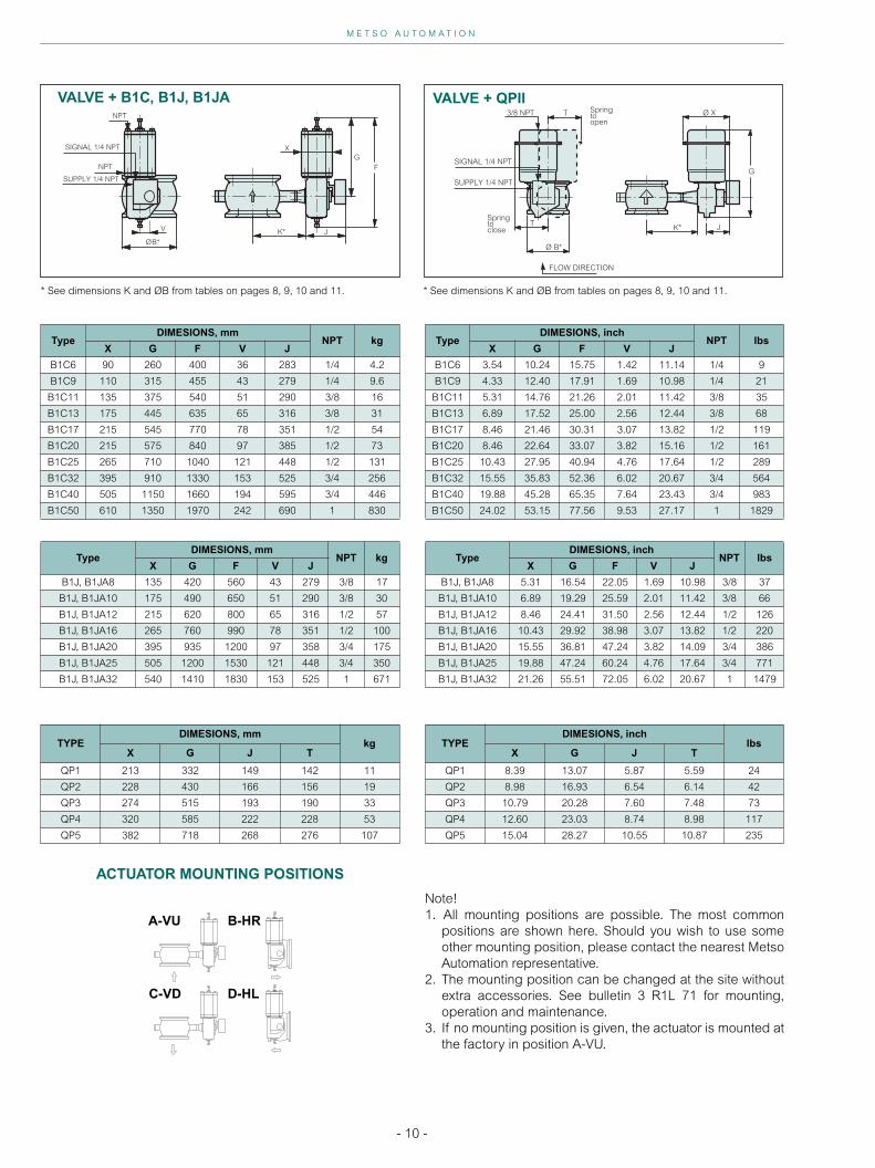
NPT kgX G F V J
B1C6 90 260 400 36 283 1/4 4.2
B1C9 110 315 455 43 279 1/4 9.6
B1C11 135 375 540 51 290 3/8 16
B1C13 175 445 635 65 316 3/8 31
B1C17 215 545 770 78 351 1/2 54
B1C20 215 575 840 97 385 1/2 73
B1C25 265 710 1040 121 448 1/2 131
B1C32 395 910 1330 153 525 3/4 256
B1C40 505 1150 1660 194 595 3/4 446
B1C50 610 1350 1970 242 690 1 830
TypeDIMESIONS, inch
NPT lbsX G F V J
B1C6 3.54 10.24 15.75 1.42 11.14 1/4 9
B1C9 4.33 12.40 17.91 1.69 10.98 1/4 21
B1C11 5.31 14.76 21.26 2.01 11.42 3/8 35
B1C13 6.89 17.52 25.00 2.56 12.44 3/8 68
B1C17 8.46 21.46 30.31 3.07 13.82 1/2 119
B1C20 8.46 22.64 33.07 3.82 15.16 1/2 161
B1C25 10.43 27.95 40.94 4.76 17.64 1/2 289
B1C32 15.55 35.83 52.36 6.02 20.67 3/4 564
B1C40 19.88 45.28 65.35 7.64 23.43 3/4 983
B1C50 24.02 53.15 77.56 9.53 27.17 1 1829
VALVE + B1C, B1J, B1JA
SIGNAL 1/4 NPT
SUPPLY 1/4 NPT
NPT
NPT F
K*ØB*
J
GX
V
* See dimensions K and ØB from tables on pages 8, 9, 10 and 11.
TypeDIMESIONS, mm
NPT kgX G F V J
B1J, B1JA8 135 420 560 43 279 3/8 17
B1J, B1JA10 175 490 650 51 290 3/8 30
B1J, B1JA12 215 620 800 65 316 1/2 57
B1J, B1JA16 265 760 990 78 351 1/2 100
B1J, B1JA20 395 935 1200 97 358 3/4 175
B1J, B1JA25 505 1200 1530 121 448 3/4 350
B1J, B1JA32 540 1410 1830 153 525 1 671
TypeDIMESIONS, inch
NPT lbsX G F V J
B1J, B1JA8 5.31 16.54 22.05 1.69 10.98 3/8 37
B1J, B1JA10 6.89 19.29 25.59 2.01 11.42 3/8 66
B1J, B1JA12 8.46 24.41 31.50 2.56 12.44 1/2 126
B1J, B1JA16 10.43 29.92 38.98 3.07 13.82 1/2 220
B1J, B1JA20 15.55 36.81 47.24 3.82 14.09 3/4 386
B1J, B1JA25 19.88 47.24 60.24 4.76 17.64 3/4 771
B1J, B1JA32 21.26 55.51 72.05 6.02 20.67 1 1479
VALVE + QPII
* See dimensions K and ØB from tables on pages 8, 9, 10 and 11.
TYPEDIMESIONS, mm
kgX G J T
QP1 213 332 149 142 11
QP2 228 430 166 156 19
QP3 274 515 193 190 33
QP4 320 585 222 228 53
QP5 382 718 268 276 107
TYPEDIMESIONS, inch
lbsX G J T
QP1 8.39 13.07 5.87 5.59 24
QP2 8.98 16.93 6.54 6.14 42
QP3 10.79 20.28 7.60 7.48 73
QP4 12.60 23.03 8.74 8.98 117
QP5 15.04 28.27 10.55 10.87 235
ACTUATOR MOUNTING POSITIONS
Note!1. All mounting positions are possible. The most common
positions are shown here. Should you wish to use someother mounting position, please contact the nearest MetsoAutomation representative.
2. The mounting position can be changed at the site withoutextra accessories. See bulletin 3 R1L 71 for mounting,operation and maintenance.
3. If no mounting position is given, the actuator is mounted atthe factory in position A-VU.
A-VU B-HR
C-VD D-HL
G
Ø XT
T
Springtoopen
Springtoclose
3/8 NPT
SIGNAL 1/4 NPT
SUPPLY 1/4 NPT
K*
Ø B*
J
FLOW DIRECTION
N E L E S R - S E R I E S S E G M E N T V A L V E W A F E R R 1 A N D F L A N G E D R 2 1
- 11 -
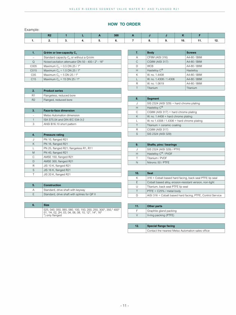
Example:
R2 1 L A 300 A J J K F
1. 2. 3. 4. 5. 6. 7 8. 9. 10. 11. 12.
HOW TO ORDER
1. Q-trim or low-capacity Cv
– Standard capacity Cv or without a Q-trim
Q Noise/cavitation attenuator DN 50 - 400 / 2" - 16"
C005 Maximum Cv = 0.5 DN 25 / 1"
C015 Maximum Cv = 1.5 DN 25 / 1"
C05 Maximum Cv = 5 DN 25 / 1"
C15 Maximum Cv = 15 DN 25 / 1"
2. Product series
R1 Flangeless, reduced bore
R2 Flanged, reduced bore
3. Face-to-face dimension
- Metso Automation dimension
1 ISA S75.04 and DIN IEC 534-3-2
3 ANSI B16.10 short pattern
4. Pressure rating
J PN 10, flanged R21
K PN 16, flanged R21
L PN 25, flanged R21; flangeless R1, R11
M PN 40, flanged R21
C AMSE 150, flanged R21
D AMSE 300, flanged R21
R JIS 10 K, flanged R21
S JIS 16 K, flanged R21
T JIS 20 K, flanged R21
5. Construction
A Standard, drive shaft with keyway
E Standard, drive shaft with splines for QP II
6. Size
025, 040, 050, 065, 080, 100, 150, 200, 250, 300*, 350,* 400*01, 1H, 02, 2H, 03, 04, 06, 08, 10, 12*, 14*, 16**) only flanged
7. Body Screws
A CF8M (AISI 316) A4-80 / B8M
C CG8M (AISI 317) A4-80 / B8M
D WCB A4-80 / B8M
H Hastelloy C Hastelloy
K W. no. 1.4408 A4-80 / B8M
L W. no. 1.4308 / 1.4306 A4-80 / B8M
R W. no. 1.0619 A4-80 / B8M
T Titanium Titanium
8. Segment
J SIS 2324 (AISI 329) + hard chrome plating
H Hastelloy C
C CG8M (AISI 317) + hard chrome plating
K W. no. 1.4408 + hard chrome plating
L W. no 1.4308 / 1.4306 + hard chrome plating
T Titanium + ceramic coating
R CG8M (AISI 317)
S SIS 2324 (AISI 329)
9. Shafts, pins / bearings
J SIS 2324 (AISI 329) / PTFE
H Hastelloy C / PVDF
T Titanium / PVDF
N Nitronic 50 / PTFE
10. Seat
K 316 + Cobalt based hard facing, back seal PTFE lip seal
E Cobalt based alloy, erosion-resistant version, non-tight
U Titanium, back seal PTFE lip seal
T PTFE + C25% / metal body
D AISI 316 + Cobalt based hard facing, PTFE, Control Service
11. Other parts
F Graphite gland packing
V V-ring packing (PTFE)
12. Special flange facing
Contact the nearest Metso Automation sales office

Metso Automation, Field Systems Division
Europe, Levytie 6, P.O.Box 310, 00811 Helsinki, Finland. Tel.int +358 20 483 150. Fax int. +358 20 483 151North America, 42 Bowditch Drive, P.O. Box 8004, 01545 Shrewsbury, USA. Tel. int +1-508-852-3567. Fax int. +1-508-852-3562
Latin America, Av. Central, 181- Chácaras Reunidas, 12238-430, São José dos Campos, SP BRAZIL.Tel. int. +55 12 3935-3500. Fax int. +55 12 3935-3535
Asia Pacific, 501 Orchard Road, #05-09 Wheelock Place, 238880 Singapore. Tel. int. +65 735 5200. Fax int. +65 735 4566www.metsoautomation.com
M E T S O A U T O M A T I O N
Subject to change without prior notice.