Embed Size (px)
Citation preview

Negative-Mass Hydrodynamics in a Spin-Orbit–Coupled Bose-Einstein Condensate
M. A. Khamehchi,1 Khalid Hossain,1 M. E. Mossman,1 Yongping Zhang,2, 3, ∗
Th. Busch,2, † Michael McNeil Forbes,1, 4, ‡ and P. Engels1, §1Department of Physics and Astronomy, Washington State University,Pullman, WA 99164, USA
2Quantum Systems Unit, OIST Graduate University,Onna, Okinawa 904-0495, Japan3Department of Physics, Shanghai University,Shanghai 200444, China
4Department of Physics, University of Washington,Seattle, WA 98105, USA
A negative effective mass can be realized in quantum systems by engineering the dispersion re-lation. A powerful method is provided by spin-orbit coupling, which is currently at the center ofintense research efforts. Here we measure an expanding spin-orbit coupled Bose-Einstein conden-sate whose dispersion features a region of negative effective mass. We observe a range of dynamicalphenomena, including the breaking of parity and of Galilean covariance, dynamical instabilities,and self-trapping. The experimental findings are reproduced by a single-band Gross-Pitaevskii sim-ulation, demonstrating that the emerging features – shockwaves, soliton trains, self-trapping, etc.– originate from a modified dispersion. Our work also sheds new light on related phenomena inoptical lattices, where the underlying periodic structure often complicates their interpretation.
Newton’s laws dictate that objects accelerate in propor-tion to the applied force. An object’s mass is generallypositive, and the acceleration is thus in the same directionas the force. In some systems, however, one finds thatobjects can accelerate against the applied force, realizinga negative effective mass related to a negative curvatureof the underlying dispersion relation. Dispersions withnegative curvature are playing an increasingly importantrole in quantum hydrodynamics, fluid dynamics, and op-tics [1–8]. Superfluid Bose-Einstein condensates (becs)provide a particularly lucrative playground to investigatethis effect, due to their high reproducibility, tunability,and parametric control. In this Letter we report on theexperimental observation of negative-mass dynamics in aspin-orbit coupled (soc) bec. Modeling the experimentswith a single-band Gross-Pitaevskii equation (gpe), weclarify the underlying role of the dispersion relation.
We engineer a dispersion by exploiting Raman dressingtechniques that lead to a soc bec [9–18]. The presenceof the Raman coupling, which acts as an effective perpen-dicular Zeeman field, opens a gap at the crossing of twoseparated parabolic free-particle dispersion curves. Forsuitable parameters, the lower dispersion branch acquiresa double-well structure as a function of quasimomentumwith a region of negative curvature [see Fig. 1(a)]. Inour experiments, the bec is initially spatially well con-fined, then allowed to expand in one dimension in thepresence of 1D spin-orbit coupling. We observe excep-tionally rich dynamics, including the breaking of Galileancovariance, which directly manifests as an anisotropic ex-pansion of the symmetric initial state [see Fig. 1(b)]. Astheir quasimomentum increases, atoms on one side enterthe negative-mass regime and slow down, demonstratinga self-trapping effect. Related to the onset of the neg-ative effective mass are a limiting group velocity and adynamical instability [19–21] that leads to the formationof shockwaves and solitons.
Our results suggest that a modified dispersion and the
Eff
ective
ma
ss [
mR
b]
En
erg
y [
ER
]
0 ms
10 ms
14 ms100m
b
Quasimomentum [ℏkR]
FIG. 1. (a) Schematic representation of the 1D expansion ofa soc bec. The asymmetry of the dispersion relation (solidcurve) causes an asymmetric expansion of the condensate dueto the variation of the effective mass. The dashed lines in-dicate the effective mass, and the shaded area indicates theregion of negative effective mass. The parameters used for cal-culating the dispersion are Ω = 2.5ER and δ = 1.36ER. Thecolor gradient in the dispersion shows the spin polarization ofthe state. (b) Experimental tof images of the effectively 1Dexpanding soc bec for expansion times of 0, 10 and 14ms.
corresponding negative effective mass also underlie var-ious “self-trapping” effects seen in optical lattice experi-ments [22–26]. However, in optical lattices, the origin ofthe self-trapping effect has been the subject of some con-troversy due to the occurrence of the underlying periodicpotential. This complication is absent on our work.
We start with a bec of approximately 105 87Rb atomsconfined in a cigar-shaped trap oriented along the x axisof a far-detuned crossed dipole trap (see [27] for details).A spin-orbit coupling is induced along the x axis by twoRaman laser beams that coherently couple atoms in the
arX
iv:1
612.
0405
5v2
[co
nd-m
at.q
uant
-gas
] 1
9 A
pr 2
017
2
0
10
20
30
40
50
x[m
icro
n]
Typical error bar:
5ms
a
10ms
‹ = 2:71ER
15ms 20ms 25ms
−60
−40
−20
0
20
40
0 5 10 15 20
t [ms]
−60
−40
−20
0
20
40
5ms
b
10ms
‹ = 1:36ER
15ms 20ms 25ms
0 5 10 15 20
t [ms]
5ms
c
10ms
‹ = 0:54ER
15ms 20ms 25ms
0 5 10 15 20
t [ms]
0:0
0:5
1:0
n=n
ma
x
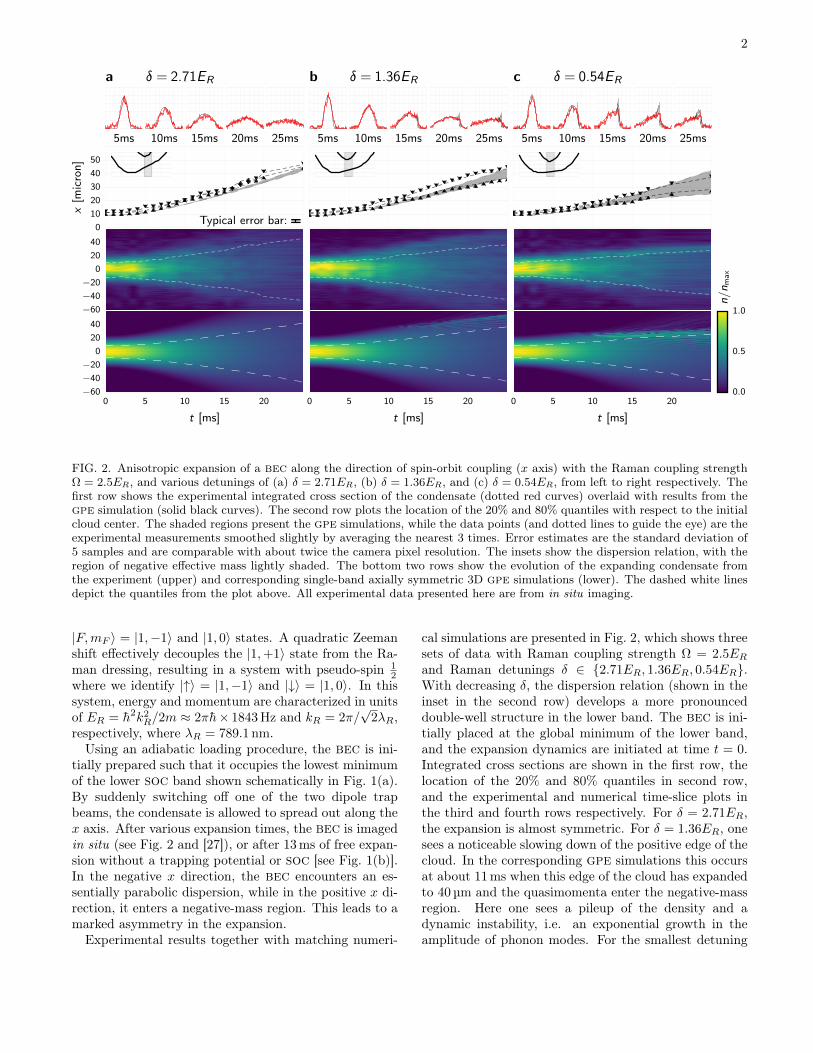
FIG. 2. Anisotropic expansion of a bec along the direction of spin-orbit coupling (x axis) with the Raman coupling strengthΩ = 2.5ER, and various detunings of (a) δ = 2.71ER, (b) δ = 1.36ER, and (c) δ = 0.54ER, from left to right respectively. Thefirst row shows the experimental integrated cross section of the condensate (dotted red curves) overlaid with results from thegpe simulation (solid black curves). The second row plots the location of the 20% and 80% quantiles with respect to the initialcloud center. The shaded regions present the gpe simulations, while the data points (and dotted lines to guide the eye) are theexperimental measurements smoothed slightly by averaging the nearest 3 times. Error estimates are the standard deviation of5 samples and are comparable with about twice the camera pixel resolution. The insets show the dispersion relation, with theregion of negative effective mass lightly shaded. The bottom two rows show the evolution of the expanding condensate fromthe experiment (upper) and corresponding single-band axially symmetric 3D gpe simulations (lower). The dashed white linesdepict the quantiles from the plot above. All experimental data presented here are from in situ imaging.
|F,mF 〉 = |1,−1〉 and |1, 0〉 states. A quadratic Zeemanshift effectively decouples the |1,+1〉 state from the Ra-man dressing, resulting in a system with pseudo-spin 1
2where we identify |↑〉 = |1,−1〉 and |↓〉 = |1, 0〉. In thissystem, energy and momentum are characterized in unitsof ER = h2k2
R/2m ≈ 2πh× 1843 Hz and kR = 2π/√
2λR,respectively, where λR = 789.1 nm.
Using an adiabatic loading procedure, the bec is ini-tially prepared such that it occupies the lowest minimumof the lower soc band shown schematically in Fig. 1(a).By suddenly switching off one of the two dipole trapbeams, the condensate is allowed to spread out along thex axis. After various expansion times, the bec is imagedin situ (see Fig. 2 and [27]), or after 13ms of free expan-sion without a trapping potential or soc [see Fig. 1(b)].In the negative x direction, the bec encounters an es-sentially parabolic dispersion, while in the positive x di-rection, it enters a negative-mass region. This leads to amarked asymmetry in the expansion.
Experimental results together with matching numeri-
cal simulations are presented in Fig. 2, which shows threesets of data with Raman coupling strength Ω = 2.5ERand Raman detunings δ ∈ 2.71ER, 1.36ER, 0.54ER.With decreasing δ, the dispersion relation (shown in theinset in the second row) develops a more pronounceddouble-well structure in the lower band. The bec is ini-tially placed at the global minimum of the lower band,and the expansion dynamics are initiated at time t = 0.Integrated cross sections are shown in the first row, thelocation of the 20% and 80% quantiles in second row,and the experimental and numerical time-slice plots inthe third and fourth rows respectively. For δ = 2.71ER,the expansion is almost symmetric. For δ = 1.36ER, onesees a noticeable slowing down of the positive edge of thecloud. In the corresponding gpe simulations this occursat about 11ms when this edge of the cloud has expandedto 40 µm and the quasimomenta enter the negative-massregion. Here one sees a pileup of the density and adynamic instability, i.e. an exponential growth in theamplitude of phonon modes. For the smallest detuning

3
δ = 0.54ER, the effect is even more pronounced, and inthe corresponding gpe simulations, the pileup and insta-bility start sooner at about 8ms and 25 µm.
At the lowest Raman detuning (δ = 0.54ER), the ex-periments show a slowdown at approximately 15ms inthe negative edge, which is not seen in the gpe simula-tions. We speculate that this is due to finite tempera-ture allowing a population in the second local minimum,requiring more sophisticated simulations (see e.g. [28]).Aside from this effect, we see good agreement betweenthe experiment and zero-temperature gpe simulations,as is expected due to the sizable roton gap (hence smallnoncondensed fraction [29]) and weak interactions [30].[31]
This justifies the description of the dynamics with acoupled set of gpes describing the two spin components:
ih∂
∂t
(|↑〉|↓〉
)=
(p2
2m + V↑Ω2 e
2ikRx
Ω2 e−2ikRx p2
2m + V↓
)·(|↑〉|↓〉
), (1a)
V↑/↓ = −µ± δ
2+ g↑↑/↑↓n↑ + g↑↓/↓↓n↓ (1b)
where p = −ih ~∇ is the momentum operator, µ is a com-mon chemical potential, kR is the Raman wave vector,gab = 4πh2aab/m, and aab are the S-wave scatteringlengths. For the |↑〉 = |1,−1〉 and |↓〉 = |1, 0〉 hyperfinestates of 87Rb, the scattering lengths are almost equaland for our numerics we take a↑↑ = a↑↓ = a↓↓ = as. Wecompare our experimental results with 3D axially sym-metric simulations for ω⊥ = 2π × 162 Hz and realisticexperimental parameters.
One of the theoretical results we wish to convey is thatin many cases (e.g., Refs. [32, 33]), a single-band modelcan capture the essential dynamics with modified disper-sion:
ih∂
∂t|ψ〉 = [E−(p) + gn+ Vext(x)] |ψ〉 (2)
where E−(p) is the dispersion of the lower band obtainedby diagonalizing Eq. (1) for homogeneous states. Forinhomogeneous densities this picture is locally valid forslowly varying densities, similar to the Thomas-Fermi ap-proximation, and remains valid as long as the system isgently excited compared to the band separation, whichis proportional to the strength Ω of the Raman coupling.With our parameters, the single-band model exhibits al-most identical results to the multiband description, quan-titatively reproducing many aspects of the experiment.The approximate equality of the coupling constants al-lows one to define a spin-quasimomentum mapping thatrelates the two-component spin populations n↑ and n↓ tothe quasimomentum q of the single-component state:
n↓ − n↑n↓ + n↑
=k − d√
(k − d)2
+ w2
, (3)
where we have defined the dimensionless parameters k =p/hkR, d = δ/4ER, and w = Ω/4ER. Our simulationssolve this model with a discrete variable representation(dvr) basis (see, e.g., Ref. [34]) with 4096 × 128 latticepoints in a periodic tube of length 276µm and radius10.8µm. This greatly simplified analysis shows that allof the interesting phenomena observed in the experiment– asymmetric expansion, the pileup, slowing down, andinstabilities – follow from the modified dispersion rela-tionship.
Having introduced the single-component theory, wenow derive the hydrodynamics of this model by effectinga Madelung transformation ψ =
√neiφ where n(~x, t) =
n↑ + n↓ is the total density at position ~x and time t,and the phase φ(~x, t) acts as a quasimomentum poten-tial ~p = h ~∇φ. The hydrodynamic equations are
∂
∂tn+ ~∇ · (n~v) = 0, (4a)
∂~v∗∂t
+ (~v∗ · ~∇)~v∗ = M−1∗ · (
~F︷ ︸︸ ︷− ~∇[Veff + VQ]), (4b)
[M−1∗ ]ij =
∂E−(~p)
∂pi∂pj, [~v∗]i =
∂E−(~p)
∂pi, (4c)
where ~v is the group velocity and ~j = ~vn is the currentdensity. Veff = Vext(~x, t) + gn(~x, t) is the effective po-tential, including both the external potential and mean-field effects. What differs from the usual Madelung equa-tions is that third and higher derivatives of the disper-sion E−(~p) affect the velocity ~v∗ and quantum poten-tial VQ(n, ~p). While for homogeneous matter, ~v = ~v∗,this relationship is broken in inhomogeneous matter andthe quantum potential acquires terms beyond the usualquantum pressure term VQ(n) ∝ ∇2
√n/√n. For ap-
proximately homogeneous sections of the cloud, however,these corrections are small: ~v ≈ ~v∗ and the usual hydro-dynamic behavior is realized. In particular, ∂~v/∂t ≈M−1∗ · ~F , so that the group velocity responds classically,
accelerating against the force ~F if the effective mass isnegative. The experiment may be qualitatively explainedusing a Thomas-Fermi–like approximation where eachpoint of the cloud is locally described by a plane-wavewith local quasimomentum p. Initially, equilibrium isestablished between the external trapping force −∇Vextand the internal mean-field pressure −∇(gn), with thequasimomentum p = p0 minimizing the kinetic energyE′−(p0) = 0. About this minimum, the effective mass ispositive, so once the trapping potential Vext is reduced,the cloud starts to expand due to the mean-field pres-sure, generating an outward group velocity and quasimo-menta. As the quasimomentum along the positive x-axisapproaches the negative-mass region (see Fig. 3), the ac-celeration slows significantly compared with the acceler-ation along the negative axis, leading to the asymmetricexpansion seen in Fig. 2: a manifestation of the broken

4
10 15 20 25 30
t [ms]
35
40
45
50
55
60x
[mic
ron
]
0:00
0:08
0:16
0:24
0:32
0:40
0:48
0:56
0:64
n=n
ma
x
FIG. 3. Zoom of a 1D simulation matching the lower mid-dle frame of Fig. 2 showing the total density n = n↑ + n↓ asa function of time in the region where the dynamic instabil-ity first appears. Dashed lines are the three group velocitiesvg = E′−(k) at the quasimomenta k where the inverse effectivemass m−1
∗ = E′′−(k) first becomes negative (steepest line), thepoint of maximum m−1
∗ (middle), and the point where them−1∗ returns to positive (least steep line). Red points demon-
strate where the local quasimomentum lies in the negative-mass region. Note that, as described in the text, the pileupinitially contains many density fluctuations, but sharpens assolitons and phonons “radiate” energy away from the wall.
Galilean covariance and parity in soc systems. Once thequasimomentum enters the negative-mass region, the ac-celeration opposes the force, and the cloud experiencesthe “self-trapping” effect where the positive mean-fieldpressure tends to prevent further expansion.
A similar effect has been reported in optical latticesnear the edge of the Brillouin zone [22, 23, 35]. These“self-trapping” effects in lattices have been attributed toseveral different phenomena. One, based on a Joseph-son effect with suppressed tunneling between neighbor-ing sites [23, 32], was predicted from a variational frame-work [36]. Another explanation is that the sharp bound-ary is a “gap soliton” [37], though this explanation is dis-puted by [32] on the basis that solitons should remainstable whereas the latter observe self-trapping only fora finite period of time. Finally, self-trapping has beenexplained in terms of the Peierls-Nabarro energy bar-rier [38]. In all of these cases, the self-trapping occurswhere the effective mass becomes negative, but the in-terpretation of the self-trapping effect in optical latticesis complicated by the presence of spatial modulations inthe potential.
The beauty of engineering dispersions with soc becsis that lattice complications are removed. The successof the single-band model in reproducing the experimentdemonstrates clearly that the self-trapping results fromthe effective dispersion relationship. A single-band modelusing the dispersion of the lowest band in an optical lat-tice is able to explain the previous observation of self-trapping in lattice systems, clearly demonstrating theimportance of the band structure and deemphasizing therole of the underlying lattice geometry of coupled wells.This result is confirmed by using a tight-binding approx-
imation to map the optical lattice of Ref. [32] to a sin-gle band model, which reproduces their results. In oursimulations, although the boundary appears to be verystable, it is “leaky”. This can be seen from Fig. 3 wherethe boundary maintains its shape, but permits a smallnumber of fast moving particles to escape. Similarly, inoptical lattice systems such fast moving particles are re-sponsible for the continued increase in the width of thecloud seen by [32] even though the boundary remainsstopped. This may resolve the apparent discrepancy be-tween [32] and [37] as a quasistable but leaky gap soliton.
What sets the limiting velocity of the expanding edge?In the optical lattice system of Ref. [22], the limiting ve-locity was observed to lie at the inflection point wherethe mass first starts to become negative. In contrast, ourgpe simulations for soc becs clearly show this limitingvelocity to lie fully inside the negative-mass region, nearthe point of maximum negative acceleration (maximumnegative inverse effective mass) (see Fig. 3). While thisqualitatively describes the limiting velocity, the full ef-fect is somewhat subtle. The limiting velocity ultimatelydepends on several factors, including the preparation ofthe system [39]. It requires a quasistable boundary whichis tied to the negative effective mass through a dynam-ical instability. From the gpe simulations, the pictureemerges that once the cloud enters the negative-mass re-gion, small fluctuations grow exponentially forming thesharp boundary of the cloud. Initially these growingmodes appear chaotic, but as is typical with dispersiveshock-waves (see [40] and references therein), energy is“radiated” from the boundary in the form of phononsand soliton trains that are clearly visible in Fig. 3. Asenergy is dissipated, the boundary appears to sharpendue to nonlinear effects. This seems critically connectedto the negative effective mass as a similar boundary withpositive mass dispersion broadens [39].
In conclusion, we have studied negative-mass hydro-dynamics both experimentally and theoretically in anexpanding spin-orbit coupled Bose-Einstein condensate.The experimental results are quantitatively reproducedwith an effective single-band zero-temperature gpe-likemodel derived from the soc Hamiltonian. With thismodel, we see that the pileup and subsequent bound-ary behavior are intimately related to the presence of anegative effective mass m−1
∗ = E′′−(p) in the effective dis-persion for the band. From linear response theory, onefinds a dynamical instability closely associated with thenegative effective mass that leads to the sudden increasein density. The boundary clearly demonstrates radiationof phonons and soliton trains, which appear to removeenergy from the region, thereby allowing the boundaryto stabilize. The stability of the boundary and its finalvelocity depend critically on the existence of a negativeeffective mass. With this work, we have also clarifiedthe interpretation of self-trapping phenomena observedin optical lattices [23, 32], demonstrating that this is nat-

5
urally explained by a negative effective mass. Spin-orbitcoupling provides a powerful tool for engineering the dis-persion E−(p) without the additional complications ofspatial modulations that appear in the context of opticallattices.
Acknowledgements: We thank Mark Hoefer for use-ful discussions. This work was supported in part by aWashington State University (wsu) New Faculty SeedGrant, and the Okinawa Institute of Science and Tech-nology Graduate University. P. E. acknowledges fund-ing from the National Science Foundation (nsf) undergrant No. PHY-1607495. Y. Z. is supported in part bythe Thousand Young Talent Program of China, and theEastern Scholar Program of Shanghai.
REFERENCES
[1] M. A. H. Tucker and A. F. G. Wyatt, “Direct evidence forr− rotons having antiparallel momentum and velocity,”Science 283, 1150–1152 (1999).
[2] Nicholas K. Lowman and M. A. Hoefer, “Dispersive shockwaves in viscously deformable media,” J. Fluid Mech.718, 524–557 (2013).
[3] Matteo Conforti and Stefano Trillo, “Dispersive waveemission from wave breaking,” Opt. Lett. 38, 3815–3818(2013).
[4] Matteo Conforti, Fabio Baronio, and Stefano Trillo,“Resonant radiation shed by dispersive shock waves,”Phys. Rev. A 89, 013807 (2014).
[5] Matteo Conforti and Stefano Trillo, “Radiative effectsdriven by shock waves in cavity-less four-wave mixingcombs,” Opt. Lett. 39, 5760–5763 (2014).
[6] Stefania Malaguti, Matteo Conforti, and Stefano Trillo,“Dispersive radiation induced by shock waves in passiveresonators,” Opt. Lett. 39, 5626–5629 (2014).
[7] Matteo Conforti, Stefano Trillo, Arnaud Mussot, andAlexandre Kudlinski, “Parametric excitation of multi-ple resonant radiations from localized wavepackets,” Sci.Rep. 5, 9433 EP – (2015).
[8] Gennady A. El and Noel F. Smyth, “Radiating dispersiveshock waves in non-local optical media,” Proc. Roy. Soc.(London) A 472, 20150633 (2016).
[9] Y. J. Lin, K. Jimenez-Garcia, and I. B. Spielman, “Spin-orbit-coupled Bose-Einstein condensates,” Nature 471,83–86 (2011).
[10] PengjunWang, Zeng-Qiang Yu, Zhengkun Fu, Jiao Miao,Lianghui Huang, Shijie Chai, Hui Zhai, and Jing Zhang,“Spin-orbit coupled degenerate fermi gases,” Phys. Rev.Lett. 109, 095301 (2012).
[11] Lawrence W. Cheuk, Ariel T. Sommer, Zoran Hadz-ibabic, Tarik Yefsah, Waseem S. Bakr, and Martin W.Zwierlein, “Spin-injection spectroscopy of a spin-orbitcoupled fermi gas,” Phys. Rev. Lett. 109, 095302 (2012).
[12] Jin-Yi Zhang, Si-Cong Ji, Zhu Chen, Long Zhang, Zhi-Dong Du, Bo Yan, Ge-Sheng Pan, Bo Zhao, You-JinDeng, Hui Zhai, Shuai Chen, and Jian-Wei Pan, “Col-
lective dipole oscillations of a spin-orbit coupled Bose-Einstein condensate,” Phys. Rev. Lett. 109, 115301(2012).
[13] Chunlei Qu, Chris Hamner, Ming Gong, ChuanweiZhang, and Peter Engels, “Observation of Zitterbewe-gung in a spin-orbit-coupled Bose-Einstein condensate,”Phys. Rev. A 88, 021604 (2013).
[14] Abraham J. Olson, Su-Ju Wang, Robert J. Niffeneg-ger, Chuan-Hsun Li, Chris H. Greene, and Yong P.Chen, “Tunable landau-zener transitions in a spin-orbit-coupled Bose-Einstein condensate,” Phys. Rev. A 90,013616 (2014).
[15] C. Hamner, Yongping Zhang, M. A. Khamehchi,Matthew J. Davis, and P. Engels, “Spin-orbit-coupledBose-Einstein condensates in a one-dimensional opticallattice,” Phys. Rev. Lett. 114, 070401 (2015).
[16] Xinyu Luo, Lingna Wu, Ruquan Wang, and L You,“Atomic spin orbit coupling synthesized with gradientmagnetic fields,” J. Phys.: Conf. Ser. 635, 012013 (2015);Xinyu Luo, Lingna Wu, Jiyao Chen, Qing Guan, KuiyiGao, Zhi-Fang Xu, L. You, and Ruquan Wang, “Tunableatomic spin-orbit coupling synthesized with a modulat-ing gradient magnetic field,” Scientific Reports 6, 18983(2016).
[17] Lianghui Huang, Zengming Meng, Pengjun Wang, PengPeng, Shao-Liang Zhang, Liangchao Chen, Donghao Li,Qi Zhou, and Jing Zhang, “Experimental realization oftwo-dimensional synthetic spin-orbit coupling in ultra-cold fermi gases,” Nat. Phys. 12, 540–544 (2016).
[18] Zhan Wu, Long Zhang, Wei Sun, Xiao-Tian Xu, Bao-Zong Wang, Si-Cong Ji, Youjin Deng, Shuai Chen,Xiong-Jun Liu, and Jian-Wei Pan, “Realization of Two-Dimensional Spin-orbit Coupling for Bose-Einstein Con-densates,” (2015), arXiv:1511.08170.
[19] L. Fallani, L. De Sarlo, J. E. Lye, M. Modugno, R. Saers,C. Fort, and M. Inguscio, “Observation of dynamicalinstability for a Bose-Einstein condensate in a moving1d optical lattice,” Phys. Rev. Lett. 93, 140406 (2004),arXiv:cond-mat/0404045.
[20] Immanuel Bloch, “Ultracold quantum gases in opticallattices,” Nat. Phys. 1, 23–30 (2005).
[21] Ishfaq Ahmad Bhat, T. Mithun, B. A. Malomed, andK. Porsezian, “Modulational instability in binary spin-orbit-coupled bose-einstein condensates,” Phys. Rev. A92, 063606 (2015).
[22] B. Eiermann, P. Treutlein, Th. Anker, M. Albiez,M. Taglieber, K.-P. Marzlin, and M. K. Oberthaler,“Dispersion management for atomic matter waves,”Phys. Rev. Lett. 91, 060402 (2003).
[23] Th. Anker, M. Albiez, R. Gati, S. Hunsmann, B. Eier-mann, A. Trombettoni, and M. K. Oberthaler, “Nonlin-ear self-trapping of matter waves in periodic potentials,”Phys. Rev. Lett. 94, 020403 (2005).
[24] K. Henderson, H. Kelkar, B. Gutiérrez-Medina, T. C. Li,and M. G. Raizen, “Experimental study of the role ofatomic interactions on quantum transport,” Phys. Rev.Lett. 96, 150401 (2006).
[25] Aaron Reinhard, Jean-Félix Riou, Laura A. Zundel,David S. Weiss, Shuming Li, Ana Maria Rey, and RafaelHipolito, “Self-trapping in an array of coupled 1d Bosegases,” Phys. Rev. Lett. 110, 033001 (2013).
[26] J. P. Ronzheimer, M. Schreiber, S. Braun, S. S. Hodg-man, S. Langer, I. P. McCulloch, F. Heidrich-Meisner,I. Bloch, and U. Schneider, “Expansion dynamics of in-

0
teracting bosons in homogeneous lattices in one and twodimensions,” Phys. Rev. Lett. 110, 205301 (2013).
[27] See Supplemental Material at [URL will be inserted bypublisher] for high-resolution images and details aboutthe experimental preparation and analysis.
[28] A. Minguzzi, S. Succi, F. Toschi, M. P. Tosi, and P. Vig-nolo, “Numerical methods for atomic quantum gases withapplications to bose–einstein condensates and to ultra-cold fermions,” Phys. Rep. 395, 223–355 (2004); Nick P.Proukakis, Simon A. Gardiner, Matthew J. Davis, andMarzena Szymanska, eds., Quantum Gases: Finite Tem-perature and Non-Equilibrium Dynamics, Cold Atoms,Vol. 1 (Imperial College Press, London, 2013).
[29] Yi-Cai Zhang, Zeng-Qiang Yu, Tai Kai Ng, ShizhongZhang, Lev Pitaevskii, and Sandro Stringari, “Super-fluid Density of a Spin-orbit Coupled Bose Gas,” Phys.Rev. A 94, 033635 (2016), arXiv:1605.02136.
[30] The scattering lengths are a↑↑ = 100.40a0, a↓↓ =100.86a0, and a↑↓ = 100.41a0 [31], so that the dimen-sionless gas parameter na3 < 3× 10⁻⁵ 10−3.
[31] S. J. J. M. F. Kokkelmans, (private communication);B. J. Verhaar, E. G. M. van Kempen, and S. J. J. M. F.Kokkelmans, “Predicting scattering properties of ultra-cold atoms: Adiabatic accumulated phase method andmass scaling,” Phys. Rev. A 79, 032711 (2009).
[32] Bingbing Wang, Panming Fu, Jie Liu, and Biao Wu,“Self-trapping of Bose-Einstein condensates in opticallattices,” Phys. Rev. A 74, 063610 (2006).
[33] Yan Li, Chunlei Qu, Yongsheng Zhang, and ChuanweiZhang, “Dynamical spin-density waves in a spin-orbit-coupled Bose-Einstein condensate,” Phys. Rev. A 92,013635 (2015).
[34] Robert G. Littlejohn and Matthew Cargo, “Bessel dis-crete variable representation bases,” J. Chem. Phys. 117,27–36 (2002).
[35] Rockson Chang, Shreyas Potnis, Ramon Ramos, ChaoZhuang, Matin Hallaji, Alex Hayat, Federico Duque-Gomez, J. E. Sipe, and Aephraim M. Steinberg, “Ob-serving the onset of effective mass,” Phys. Rev. Lett. 112,170404 (2014).
[36] Andrea Trombettoni and Augusto Smerzi, “Discrete soli-tons and breathers with dilute Bose-Einstein conden-sates,” Phys. Rev. Lett. 86, 2353–2356 (2001).
[37] Tristram J. Alexander, Elena A. Ostrovskaya, andYuri S. Kivshar, “Self-trapped nonlinear matter waves inperiodic potentials,” Phys. Rev. Lett. 96, 040401 (2006).
[38] H. Hennig, T. Neff, and R. Fleischmann, “Dynamicalphase diagram of gaussian wave packets in optical lat-tices,” Phys. Rev. E 93, 032219 (2016).
[39] Edward Delikatney, Khalid Hossain, and Michael Mc-Neil Forbes, in preperation.
[40] G. A. El and M. A. Hoefer, “Dispersive shock waves andmodulation theory,” Physica D: Nonlinear Phenomena333, 11–65 (2016), arXiv:1602.06163

1
NUMERICAL SIMULATIONS
In principle, since the trap is highly elongated, one canuse an effective 1D simulation by tuning the couplingconstants appropriately as described in [41, 42]. For theexperimental parameters, this effective 1D approxima-tion works quite well, but since there are some radialexcitations, we compare directly with 3D axially symmet-ric simulation with ω⊥ = 2π × 162 Hz. Our simulationsare performed using an axially symmetric dvr basis (seee.g. [34]) with 4096×128 lattice points in a periodic tubeof length 276 µm and radius 10.8µm.
In Fig. 4 we compare the single-band model (2) to thefull two-component model (1), demonstrating that forthe experiment under consideration, all the relevant phe-nomena result purely from the modified dispersion rela-tionship E−(p). Even when studying systems with signif-icant population of the upper band such as the dynamicalspin-density waves demonstrated in [33], we find that thesingle-component model (2) captures most of the bulkeffects: i.e. it correctly models the dynamical behaviorof the total density n↑ + n↓, but the significant popula-tion of the upper branch breaks the spin-quasimomentummapping (3). In this figure we also compare 3D axially-symmetric simulations with 1D simulation where we have
−60
−40
−20
0
20
40
60
−60
−40
−20
0
20
40
60
0 5 10 15 20 25 30
t [ms]
−60
−40
−20
0
20
40
60
x[m
icro
n]
0:0
0:1
0:2
0:3
0:4
0:5
0:6
0:7
0:8
0:9
1:0
n=n
ma
x
FIG. 4. Comparison between simulations. Comparisonof the full two-component 1D gpe model (1) (top) with the1D single-band model (2) (middle) and the axially symmetric3D single-band model (bottom) for detuning δ = 0.54ER andRaman coupling strength Ω = 2.5ER.
tuned the coupling constant using the relationship in [41].This comparison demonstrates that, while the 1D simu-lations qualitatively match the experiments, they exhibitsome quantitative differences with the 3D simulations.
Our simulations here explore only the dynamics of thecondensate. Extensions to the gpes (see e.g. [28] forreviews) are require to capture the dynamics of the non-condensed fraction due to finite temperature, and quan-tum fluctuations, but are beyond the score of the presentwork. (For example, a significant non-condensed frac-tion is expected when the gap in the roton branch van-ishes [29]. For our parameters, the roton branch stillhas a large gap.) The deviations described in the textbetween gpe simulations and experiment at the lowestRaman detuning will provide a way to test these exten-sions.
EXPERIMENTAL METHODS
The experiment begins with approximately 105 87Rbatoms confined by two trapping dipole beams whichtogether produce harmonic trapping frequencies of(ωx, ωy, ωz) = 2π×(26, 170 and 154)Hz. soc is thengenerated along the x-axis by two perpendicular Ra-man beams of wavelength λR = 789.1 nm [see Fig. 5(a)].The Raman beams coherently couple the |F, mF 〉 =|1,−1〉 and |1, 0〉 states. A homogeneous bias field ofB ≈ 10 G is applied along the x-axis, leading to a Zee-man splitting of the atomic levels. The quadratic Zeemanshift of 7.8ER effectively decouples the |1,+1〉 state fromthe Raman dressing, resulting in a system with pseudo-spin 1
2 where we identify |↑〉 = |1,−1〉 and |↓〉 = |1, 0〉[see Fig. 5(b)]. After the atoms are dressed by the Ra-man beams with a specific Raman coupling strength
|1,-1⟩
|1,0⟩
|1,+1⟩
a b
δx
y
z
Horizont
al
Dipole
Vertical
Dipole
Raman
Raman
FIG. 5. (a) Experimental arrangement of the trap (yellow)and the Raman (green) beams. The angle between the Ramanbeams is 90. (b) Raman coupling scheme in the F = 1manifold. The |1,+1〉 state is effectively decoupled due tothe quadratic Zeeman shift induced by an external bias fieldalong the x direction.

2
Ω and detuning δ, the vertical dipole beam is rapidlyswitched off, reducing the confinement along the x-axisfrom ωx = 2π×26 Hz to ωx = 2π×1.4 Hz. This allows thesoc bec to expand along the direction of the spin-orbitcoupling, revealing the rich dynamics discussed in themain text. The extent of the cloud as depicted in Fig. 2is taken from in-trap images. Figure 1(b) depicts ex-perimental images taken after an in-trap expansion timedenoted to the left of the image, followed by 13ms freeexpansion.
COMPARISON
To supplement the comparison between the numericaland experimental results, we include in Fig. 6 a high-
resolution comparison between the numerical and exper-imental in situ images. Note that we have not addednoise or pixel averaging effects to the numerical simula-tions so that underlying features (solitons etc.) remainunobscured.
SUPPLEMENTARY REFERENCES
[41] M. Olshanii, Phys. Rev. Lett. 81, 938 (1998), URL http://link.aps.org/doi/10.1103/PhysRevLett.81.938.
[42] Y.-C. Zhang, S.-W. Song, and W.-M. Liu, Sci. Rep. 4,4992 (2014), URL http://www.ncbi.nlm.nih.gov/pmc/articles/PMC4034008/.

3
0ms
‹ = 2:71ER
1ms
2ms
3ms
4ms
5ms
6ms
7ms
8ms
9ms
10ms
11ms
12ms
13ms
14ms
15ms
16ms
17ms
18ms
19ms
20ms
−60 −40 −20 0 20 40 60
x [micron]
25ms
0ms
‹ = 1:36ER
1ms
2ms
3ms
4ms
5ms
6ms
7ms
8ms
9ms
10ms
11ms
12ms
13ms
14ms
15ms
16ms
17ms
18ms
19ms
20ms
21ms
22ms
23ms
24ms
−60 −40 −20 0 20 40 60
x [micron]
25ms
0ms
‹ = 0:54ER
1ms
2ms
3ms
4ms
5ms
6ms
7ms
8ms
9ms
10ms
11ms
12ms
13ms
14ms
15ms
16ms
17ms
20ms
−60 −40 −20 0 20 40 60
x [micron]
25ms
FIG. 6. In-situ data: Experiment and Theory. In-situ experimental integrated cross section of the condensate (dotted redcurves) overlaid with results from the axially symmetric single-band 3D gpe simulations (solid black curves) with the Ramancoupling strength Ω = 2.5ER, and various detunings of (a) δ = 2.71ER, (b) δ = 1.36ER, and (c) δ = 0.54ER, from left to rightrespectively. The top insets show the dispersion relation, with the region of negative effective mass lightly shaded.


