Embed Size (px)
Citation preview

NED Project P. MANIL – CEA/IRFU/SIS – Short Model Coils meeting #18 – 25/01/2008 – slide 1/18
SHORT MODEL COILS PROGRAM
SMC meeting #18
Pierre MANIL
CEA/IRFU/SIS1. SMC assembly
Modeling, Conception, Outstanding points
2. SMC toolingBladders & Slipshims, Bladder testing device, CERN implication
3. Ceramic insulation windingRAL experience, possible improvements
4. ScheduleBack on the agenda…

NED Project P. MANIL – CEA/IRFU/SIS – Short Model Coils meeting #18 – 25/01/2008 – slide 2/18
1. SMC assembly
P. MANIL – CEA/IRFU/SIS – Short Model Coils meeting #18 – 25/01/2008 – slide 2/18

NED Project P. MANIL – CEA/IRFU/SIS – Short Model Coils meeting #18 – 25/01/2008 – slide 3/18
SMC ASSEMBLY 1/3
MECHANICAL DESIGN PRINCIPLE
Y-pad (iron-steel)
External tube(aluminum)
X-pad(iron-steel)
Yoke(iron-steel)
COILPACK
Keys(iron)
Bladder location
courtesy of François Nunio, CEA
Y
XZ
Shell-based structure:- Aluminum shell- Iron & steel pads- Iron & steel yoke
Pre-stress at room temperaturew/ bladders and keys(in the models to come,the keys width will include theirown nominal size+ the interference key gap)
In-situ stress control- on tube- in coil pack
We have to combine relevant shell pre-stress (controlled by tube’s thickness) and bladders pre-stress (controlled by keys interferences) to define the range of coil pre-stress
NED Project P. MANIL – CEA/IRFU/SIS – Short Model Coils meeting #18 – 25/01/2008 – slide 4/18
SMC ASSEMBLY 2/3
KNOWN / UNKNOW…
Courtesy R. HafaliaH. Félice
Coil properties OKexpected field OK
Rods geometries TBD
Interface withexternal world TBD
Interface between RAL’s coil packAnd assembly TBD
Instrumentation TBD
Lateral prestress OKBladders being tested
Assembly parameters OKryoke~230 mmetube~20 mm
Iron extension OK
Detailed conceptionTBD
Finermechanical studies TBD
- Sensitivity- Mouting steps modeling…
Picture=SD01 magnet
(as an example)

NED Project P. MANIL – CEA/IRFU/SIS – Short Model Coils meeting #18 – 25/01/2008 – slide 5/18
2D MODEL ryoke 230
etube 20
ix 300
iy 0
µ 0.3
-113 MPa -125 MPa
-92 MPa-140 MPa -129 MPa
-52 MPa-156 MPa -136 MPa
-37 MPa-163 MPa -140 MPa
20%
50%
100%
120%
100%
Lorentz
138 MPa
270 MPa
168 MPa52MPa
80 MPa
147 MPa
No separation
Bladder
Cool-down
σx σVM
-102 MPa -113 MPa
-31 MPa -43 MPa
Lore
ntz
107 MPa
225 MPa
80 MPa93 MPa
70 MPa
137 MPa
Bladders
+ CoolingVery homogeneous ~ -110 MPa
Very homogeneous ~ -35 MPa
Very homogeneous ~ -120 MPa

NED Project P. MANIL – CEA/IRFU/SIS – Short Model Coils meeting #18 – 25/01/2008 – slide 6/18
SMC ASSEMBLY 3/3
PRESENT STAKES
3D modeling (CEA part)- defining rods prestress and geometries- validating the whole structure comportment
Mechanical steps- validating the new bladders (see next part) integrating 60 mm-wide bladders in the structure with Federico- validating the LHC iron needs- detailed conception and drawings
Interface with the coil pack (coherent conception):- how to offset the different coil pack sizes? Horseshoe or shims(SMC size: 419.2 x 189.2 mm – ceramic insulated coil size: 436.0 x 206.0 mm)- what horseshoe geometry?- current leads
Superconducting cable needsI confirmed this week to Thierry Boutboul and Federico that we need:- 80 m for Saclay (1 dipole = 2 double pancakes)- 160 m for RAL (2 dipoles)

NED Project P. MANIL – CEA/IRFU/SIS – Short Model Coils meeting #18 – 25/01/2008 – slide 7/18
2. SMC tooling
P. MANIL – CEA/IRFU/SIS – Short Model Coils meeting #18 – 25/01/2008 – slide 7/18

NED Project P. MANIL – CEA/IRFU/SIS – Short Model Coils meeting #18 – 25/01/2008 – slide 8/18
SMC TOOLING 1/3
BLADDERS AND SLIPSHIMS
Bladders are 420 x 60 mm (SD01: 320 x 54 mm) A set of 3 has been manufactured for tests and qualification Laser winding all along, supplier test under 5 bars pressure
Slipshims are 570 x 62 mm, already manufactured
Laminated steel shims
CourtesyR. Hafalia

NED Project P. MANIL – CEA/IRFU/SIS – Short Model Coils meeting #18 – 25/01/2008 – slide 9/18
SMC TOOLING 2/3
BLADDER TESTING DEVICEVon Mises stresses for ix=300 μm
Strain gauge

NED Project P. MANIL – CEA/IRFU/SIS – Short Model Coils meeting #18 – 25/01/2008 – slide 10/18
SMC TOOLING 3/3
CERN IMPLICATION
Final test cryostat has been identified at CERN(with Christian Giloux & Patrick Viret in Remo Maccaferri’s lab)
- AUTOCAD drawings are available (for integration at Saclay)
- Power supply is OK (up to 15-20 kA available – quench current around 14 kA)
- Thinking asked about external residual field: seems to be OK
CERN has to supply:
- water compressor or hand pump (very high pressure ~500 bars)
- instrumentation & electronics apart from mechanical (uniaxial?) gauges on assembly
- hydraulic press for rods prestress
Courtesy R. Hafalia

NED Project P. MANIL – CEA/IRFU/SIS – Short Model Coils meeting #18 – 25/01/2008 – slide 11/18
3. Ceramic insulation winding
P. MANIL – CEA/IRFU/SIS – Short Model Coils meeting #18 – 25/01/2008 – slide 11/18

NED Project P. MANIL – CEA/IRFU/SIS – Short Model Coils meeting #18 – 25/01/2008 – slide 12/18
CERAMIC INSULATION WINDING 1/4
SMC WINDING TRIAL 2 (RAL work)

NED Project P. MANIL – CEA/IRFU/SIS – Short Model Coils meeting #18 – 25/01/2008 – slide 13/18
CERAMIC INSULATION WINDING 2/4
POSSIBLE IMROVEMENTS
Cable clamping during winding- improving clamping on straight sections (butterfly screws…)- adding clamps on heads (cf. picture)- thinking about the need for final compression of the pancake for planarity
’S’ layer transition- softening the edges- machining a head clamp to maintain the transition- thinking about pre-forming…
Question : are metal shavings due to screws a danger?if it is: Teflon screws?
CourtesyPh. Daniel-
Thomas

NED Project P. MANIL – CEA/IRFU/SIS – Short Model Coils meeting #18 – 25/01/2008 – slide 14/18
CERAMIC INSULATION WINDING 3/4
NB3SN QUADRUPOLES
We will use Nb3Sn quadripoles’ winding machinefor ceramic insulated coil.
To re-design:-Support and fixation plate
-Coil pack ends-Winding clamps
Courtesy M. Segreti
Rotating support (re-used)
Cable stock
Fixation plate
Coil pack end

NED Project P. MANIL – CEA/IRFU/SIS – Short Model Coils meeting #18 – 25/01/2008 – slide 15/18
CERAMIC INSULATION WINDING 4/4
OVERLOOK
’S’ layer transition
Titanium parts
Clamping(or alternative solution)

NED Project P. MANIL – CEA/IRFU/SIS – Short Model Coils meeting #18 – 25/01/2008 – slide 16/18
4. Schedule
P. MANIL – CEA/IRFU/SIS – Short Model Coils meeting #18 – 25/01/2008 – slide 16/18

NED Project P. MANIL – CEA/IRFU/SIS – Short Model Coils meeting #18 – 25/01/2008 – slide 17/18
SCHEDULE 1/2
Steering committee of October 15 (CERN) :
Deadlines for Saclay:- SMC support structure (+ tooling) for June 15- Ceramic-insulated coil for late October
Mechanical caraterization of ceramic insulation Courtesy G. de Rijk
NED Project P. MANIL – CEA/IRFU/SIS – Short Model Coils meeting #18 – 25/01/2008 – slide 18/18
SCHEDULE 2/2
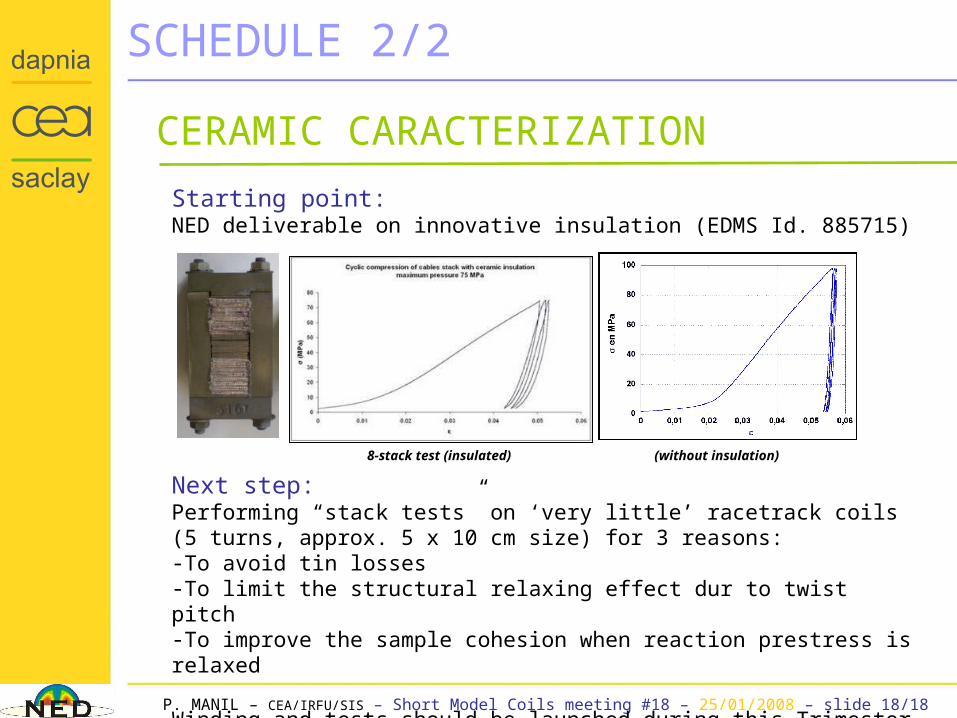
Starting point:NED deliverable on innovative insulation (EDMS Id. 885715)
Next step:Performing “stack tests” on ‘very little’ racetrack coils(5 turns, approx. 5 x 10 cm size) for 3 reasons:-To avoid tin losses-To limit the structural relaxing effect dur to twist pitch-To improve the sample cohesion when reaction prestress is relaxed
Winding and tests should be launched during this Trimester
CERAMIC CARACTERIZATION
8-stack test (insulated) (without insulation)